LS Series Little Still Instruction Manual
|
|
|
- Camron Sims
- 6 years ago
- Views:
Transcription
1
2 LS Series Little Still Instruction Manual Introduction This LS Series solvent distillation system provides safe, on-site reclamation of contaminated solvents. Use of the Little Still can save money and conserve the environment by reducing or eliminating the disposal of these solvents. Quality engineered and manufactured, the Little Still requires minimal operator involvement. When properly installed, operated, and maintained, this equipment can provide years of trouble-free service. Table of Contents Safety Precautions 2 Installation Requirements and Instructions 3 Assembly 3-4 Electrical Requirements 5 Grounding Requirements 5 Electrical Connections 6 Condenser Cooling Water Requirements 7 Quick Cool Requirements 8 Conventional Tap Water Supply 9 Instrumentation and Controls 10 Start-up and Operation 14 Maintenance Schedule 18 Service and Troubleshooting 20 Appendix 27 Common Spare Parts 27 Electrical Schematics 29 Warranty 31 For technical assistance call: or
3 Safety Precautions WARNING: READ THIS MANUAL COMPLETELY BEFORE INSTALLING AND OPERATING THIS EQUIPMENT. FAILURE TO FOLLOW THESE PRECAUTIONS CAN RESULT IN SERIOUS INJURY OR DEATH. Installation location and area must conform to requirements set by National Electric Code Class 1, Division 1, Group D for hazardous locations. Follow National Fire Protection Association guidelines for control of static electricity (NFPA 77, Recommended Practice on Static Electricity). This applies to the installation area, equipment, personnel, and all transfer and receiving containers. Ventilate all vapors from the processing area and distillation equipment according to National Fire Protection Association guidelines (NFPA 91, Standard for the Installation of Blower and Exhaust Systems for Dust, Stock, and Vapor Removal or Conveying). Follow the National Fire Protection Association recommendations for safe storage and use of flammable and combustible liquids (NFPA 30, Flammable and Combustible Liquids Code). Electrical wiring should be performed by a qualified electrician and must conform to National Electric Code Class 1, Division 1, Group D requirements for explosionproof equipment. Use only electricals labeled explosionproof (boxes, receptacles, hard conduit, etc.) for the installation and in the area. Obtain approval of the installation area and installation from your insurance and/or fire inspector. Remove any ignition sources from the area such as flames (cigarettes, torches, furnace), or sparks (grinders, non-explosionproof electrical switches and outlets, etc.). Verify proper water flow before operation to prevent accumulation of hazardous vapors. Wear proper eye and skin protection and an approved respirator when handling solvents and working with this equipment. Never process reactive solvents or materials such as gasoline, ethers, nitrocellulose, etc. Never work on or with this equipment while it is hot. Never open a hot Still. Allow a minimum of two hours or more cool-down time. 2
4 Installation Requirements and Instructions PHYSICAL SPACE REQUIREMENTS: See Safety Precautions for important information regarding the installation area. The unit must be installed on a level concrete pad/floor and protected from the weather and freezing temperatures. Approximate overall dimensions/space requirements are listed below. Additional space is required around and above the equipment for loading and unloading, storage drums, access for maintenance, etc. Equipment model(s) Width Depth Height LS-15E/15IIE 51 in. (1.3 m.) 27 in. (0.7 m.) 42 in. (1.1 m.) LS-15E/15IIE + JetVac 108 in. (2.7 m.) 27 in. (0.7 m.) 48 in. (1.2 m.) LS-55E/55IIE 75 in. (1.9 m.) 40 in. (1.0 m.) 60 in. (1.5 m.) LS-55E/55IIE + JetVac 131 in. (3.3 m.) 40 in. (1.0 m.) 60 in. (1.5 m.) IMPORTANT: If using a Little Cooler closed-loop cooling system with the Little Still, the Little Cooler must be located outside of the hazardous area. Refer to the Little Cooler Instruction Manual for further details. ASSEMBLY: See Parts Location Diagram for additional information. Remove the unit from the shipping containers and inspect for damage. If damage is detected, save all packaging and immediately report any exterior or interior damage to the freight carrier. Remove all accessories from the inside of the Still (and the JetVac s cabinet, if applicable). Install the pressure relief valve assembly into the top of the Still s lid. Face the elbow towards the rear of the unit (away from the occupied area). Attach the supplied grounding cables/clamps to the ground block on the right side of the Still. Thread the discharge hose into the discharge pipe on the right side of the Still. Omit this step if installing a JetVac (see below). SPECIAL ASSEMBLY FOR LS-15IIE AND LS-55IIE: System II Stills have additional features for automatic operation. Explanations of these features are discussed in the Instrumentation and Controls section. Install the vapor temperature gage into the control panel on the front of the Still (this gage is a delicate instrument and is packed separately to prevent damage). Attach the white wire to the positive (+) terminal and the red wire to the negative (-) terminal. Mount the gage using the two nuts provided. 3
5 SPECIAL ASSEMBLY FOR INSTALLATIONS WITH A JETVAC: When installing a JetVac attachment to a Little Still, the system is installed and assembled in a way that allows the system to operate either with or without the JetVac. Use pipe tape on all threaded connections to prevent vacuum leaks. Set the JetVac to the right of the Still, with approximately 24 inches of space between the units. Thread the discharge hose with sightglass into the JetVac s distillate port (on the left side, towards the front of the cabinet). Also thread the Y-strainer into the JetVac s vacuum port (on the left side, centered). Thread a male quick-connect onto the JetVac s metal braided hose female side. Thread a female quick-connect into the discharge of the Still (on the right side, centered in the cabinet). Thread the metal braided hose into the previously installed. Adjust the distance between the Still and JetVac until the metal braided hose quick-connects to the Still. Secure the Still and JetVac to the floor once positioned. Attach the other male quick-connect to the Still s discharge hose. This allows this discharge hose to attach directly to the Still (after disconnecting the metal braided hose) for processing without the JetVac. INSTALLATION OF THE FLAME ARRESTER TO JETVAC: The flame arrestor is designed to prevent flame from entering the distillation system through the vent pipe. Proper installation and location of the flame arrester is essential to effective operation. Installation must be inspected and approved by your insurance and/or fire inspector. Connection is made at the vent on the backside of the JetVac unit (see pg. 9 for location). The flame arrester must be piped so the arrow on the flame arrestor body points away from the distillation system and must be connected to the end of the vent pipe. Using FTI supplied piping, screw the ½ nipple into the coupling on the back of the JetVac, attached a 90º elbow to the nipple and a customer supplied connect a length of pipe to allow venting to a safe area (to the outside or other safe area as determined by your insurance or other qualified inspector). Make sure that the piping is properly supported and the flame arrestor is attached to the end of the vent pipe. Do not use pipe larger than ½ diameter. If venting unit to the outside, a gooseneck can be installed on the end of the flame arrestor to prevent rain from entering the vent piping through the flame arrestor. The gooseneck must be ½ pipe, be installed at the end of the flame arrestor and be no more that 5 long. 4
6 ELECTRICAL REQUIREMENTS: CAUTION: A qualified electrician should perform electrical connections. Improper electrical wiring can result in damage to components. See Safety Precautions for important information regarding the electrical connections. Electrical power requirements to the control panel are 240 volts, 1 phase, 50/60 hertz from a protected circuit and earth ground. If the incoming voltage is 208 volts, processing time will increase. The equipment will not operate with incoming voltages (under load) less than 208 volts. Electrical connections are made on the rear of the Still. Attach a customer supplied explosionproof circuit box to the Still s electrical conduit. If a JetVac and/or Little Cooler are used with an LS-15E/55E still, they must be wired independent of the still and manually started/stopped. Note: Customer must supply a switch to control a Little Cooler in this case. See the Little Cooler Instruction Manual for more details. System II stills can be electrically connected for automatic operation of a JetVac and/or a Little Cooler, if using a Little Cooler, a 10-amp contactor (customer supplied) must be used. See electrical connections below! Make the connections per the diagrams following: LSEII wiring for units without JetVac or Little Cooler LS15E/55IIE wiring with JetVac and Little Cooler LS15E/55IIE wiring with JetVac LS JetVac wiring for LS15E and LS55E LSJetVac wiring for LS15IIE and LS55IIE GROUNDING REQUIREMENTS: See Safety Precautions for important information on static grounding. A positive earth ground must be provided to help avoid static ignition and must be attached to all equipment, filling and receiving containers, tanks, personnel, etc. All transfer devices such as piping, hoses, and pumps must also be grounded. Several ground lugs are provided on the right side of the Still and several grounding clamps are provided. USE THEM. 5
7 LITTLE COOLER L1 L2 INCOMING POWER (SWITCHED) INCOMING POWER L1 L2 INCOMING POWER L1 A L2 1L2 LS-15E/55E STILL JETVAC Electrical connections for an LS-15E/55E LITTLE COOLER CC1 CC2 L1 L2 INCOMING POWER CUSTOMER SUPPLIED CONTACTOR B C.C. 1L2 INCOMING POWER L1 L2 TO CUSTOMER SUPPLIED CONTACTOR COIL FOR LITTLE COOLER LS-15IIE or LS-55IIE B 1L2 1L2 A 1L2 A INCOMING POWER L1 L2 JETVAC Electrical connections for a System II 6
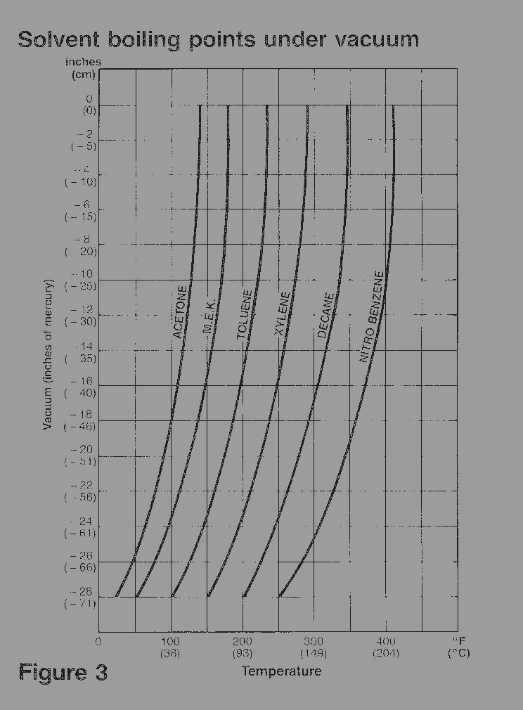
8 CONDENSER COOLING WATER REQUIREMENTS: WARNING: Improper cooling water supply can result in the accumulation of hazardous vapors (refer to Safety Precautions for ventilation information). CAUTION: Do not allow the cooling water supply to freeze. Damage to components can occur. Do not exceed 85 psi inlet water pressure. Cooling water can be supplied via tap water or from a closed-loop cooling system (e.g., a Little Cooler or cooling tower). Cooling water supply and return connections are ½ NPT female pipe and are located on the rear of the Still and JetVac. Minimum cooling water flow required for the condenser is ½ gallon per minute for the LS-15E/15IIE, and 1½ gallons per minute for the LS-55E/55IIE. Minimum requirements increase by a ½ gallon a minute when using any still in conjunction with a JetVac. Cooling water temperature must be less than 80 F or 50 F below the lowest boiling point of the solvent being processed whichever is lower (determine solvent boiling point under vacuum, if applicable). If using a hard water supply, treatment is required to prevent mineral deposit or scale accumulation within the vapor condensers and cooling coils of the cooling system. If water contains particulate, install an appropriate filter before the Still. IMPORTANT: Follow these guidelines when using a Little Cooler closed-loop cooling system. Refer to the Little Cooler Instruction Manual for further information. The Little Cooler is designed only for condenser cooling. Do not attach it to the quick-cool coil (use tap water for the quick-cool). Depending on the physical distance, height, and type of plumbing used between the Still and the Little Cooler, it may be necessary to bypass the condenser water solenoid valve. Simply remove the hose from the inlet of the solenoid valve and connect it to the water inlet of the condenser (lower connection on the condenser). There will be a slight delay before the Still will turn on when using a Little Cooler (until the cooling water begins to circulate). 7
9 QUICK COOL REQUIREMENTS NOTE: The Quick Cool is standard in the LS-15E/15IIE units. The main purpose of the quick cool coil is to rapidly cool down the distillation tank after a cycle is complete, which allows the user to run multiple shifts each day. If the user does not intend to run multiple shifts, FTI recommends not plumbing the quick cool coil. The Little Cooler is designed only for condenser cooling. Do not attach it to the quick-cool coil (use tap water for the quick cool). Plumb the quick cool coil with hard piping only. An air inlet valve must be installed to properly vent the system. This allows the line to be adequately drained after each use (see cooling diagram). Always completely drain the quick cool coil after each use or the next cycle will be prolonged and/or possible damage to the unit may occur. A check valve should be installed on the outlet side of the quick cool to prevent backpressure or back flow into the system from down steam (see cooling diagram), which will hinder the cycle time of the next cycle. Minimum cooling water flow required for the quick cool is 1-3 gallons per minute for the LS-15E/15IIE and 2-5 gallons per minute for the LS-55E/55IIE. 8
10 CONVENTIONAL TAP WATER SUPPY: Use with optional JetVac. ATMOSPHERIC. CLOSED-LOOP COOLING WATER SUPPLY: Refer to Little Cooler Instruction Manual when connecting a Little Cooler. Use with optional JetVac. ATMOSPHERIC IMPORTANT: Quick cool must be drained completely before each run. An air inlet valve is required to drain quick-cool coil. 9
11 Instrumentation and Controls LS SERIES STILLS (ALL MODELS): STOP/START - An illuminated push-button switch. Pull to activate the Still, push to terminate all functions. A green light indicates that the Still is operating within the processing cycle. IMPORTANT: The STOP/START push-button switch must be left pushed in the STOP position for a minimum of five (5) seconds before pulling on. This allows the controls to electrically reset themselves. Failure to do so will prevent the heater from operating. CYCLE TEMP - Controls the temperature that will be maintained in the area of the heater. Turn the dial to set the temperature at least 50 to 100 F above the boiling point of the solvent being processed. IMPORTANT: Determine the solvent boiling point under vacuum, if applicable. See Solvent Boiling Points Under Vacuum for additional information. LS SERIES SYSTEM II STILLS: CYCLE TIMER - This setting determines the total duration of the cycle. Turn the dial to the desired amount of time, depending on your particular solvent. If unsure as to the time required for your solvent, start at 8 hours, then observe the results. Adjust up or down, as necessary until the optimum time is determined. IMPORTANT: The minimum setting (full counter-clockwise) allows the still to process for 10 minutes, then activates the cool-down mode for 1 hour. The maximum setting (full clockwise) allows the still to process for 16 hours, then activates the cool-down mode for 1 hour. The accuracy of the timer is approximately ±15%. COOLING WATER - White indicator light. When illuminated, this light indicates that the cooling water supply to the condenser is flowing at or above the proper rate. Adjust your incoming water flow until the light stays on without flickering. If the white light does not illuminate, this may indicate that the water flow to the unit is inadequate, or the condenser cooling system or flow switch requires maintenance. HEAT - Amber indicator light. This light indicates the heater element is ON. During normal operation, this light will remain illuminated for approximately the first hour of the process, then will cycle ON and OFF to indicate that the heating system is cycling to maintain the temperature set on the Cycle Temp dial. VAPOR TEMP - Indicates the temperature of the solvent vapor before being condensed into liquid. This gage is for informational purposes only, and controls no functions. 10
12 JETVAC ATTACHMENT: STOP/START - An illuminated push-button switch. Pull to ready the JetVac s operation, push to terminate all JetVac functions. A green light indicates that the JetVac is operating within the processing cycle. IMPORTANT: The STOP/START push-button switch should remain ON (pulled) when wired for automatic operation. In this mode, the Still will automatically turn on and off the JetVac depending on the status of the Still s operation. If vacuum operation is not required for a particular process, simply push STOP/START to the STOP position. VACUUM GAGE - A gage that indicates the level of vacuum, measured in inches of mercury being generated by the JetVac measured in inches of mercury (0 to -30 Hg.). An increase in vacuum level decreases the boiling point of the solvent being processed. The vacuum level can be adjusted turning the nuts on the vac adjust valve located inside of the JetVac s cabinet. 11
13 PUSH TO STOP PULL TO START CYCLE TEMP ºF LS-15E/55E CONTROLS COOLING WATER PUSH TO STOP PULL TO START CYCLE TEMP ºF CYCLE TIMER HOURS HEAT VAPOR TEMPERATURE LS-15IIE/55IIE CONTROLS 15 PUSH TO STOP PULL TO START 30 0 VACUUM GAUGE JETVAC CONTROLS 12
14 13
15 Start-up and Operation The LS Series equipment requires minimal operator involvement. Once set up and started, the unit can operate virtually unattended until the process is complete. See Safety Precautions before operating this unit. Explanation of each control and setting can be found in Instrumentation and Controls. CAUTION: Only process neutral waste solvents with a ph between 6 and 9. Solvents outside of this safe ph range can cause damage to your LS Series equipment that is not covered under its warranty. Some solvents can become acidic or basic once heated. Periodically test the dirty solvent as well as the distillate and residue to verify a safe ph. If your ph is not in the safe zone, it must be neutralized. Consult your solvent supplier for recommendations on testing the ph and ph correction. LS-15E/55E MODELS: 1. Open the lid and remove any residues from a previous run. Make sure that the inside of the boiling chamber is clean and free of debris. CAUTION: When cleaning, use only plastic or other non-metallic utensils to avoid scratching the boiling chamber when scraping out residues. Scratching the non-stick coating results in permanent damage and voids the warranty. 2. Install a Stilbag or a Stilpan (if used, see Installing a Stilbag). If using a JetVac attachment, prepare the JetVac for operation (see Start-up and Operation: JetVac). 3. Fill the boiling chamber (ground all transfer equipment, containers, and personnel, see Safety Precautions). Do not overfill. Close the lid, make sure the lid is centered on the gasket, and secure the lid clamps. Place a clean, grounded receiving drum under the discharge hose of the Still (or JetVac, if applicable). 4. Verify that the quick-cool water supply is off and that all cooling water is drained from the quick-cool coil by opening the drain valve and breather valve. 5. Turn on the condenser s water supply. If using a Little Cooler, prepare the Little Cooler for operation (refer to the Little Cooler Instruction Manual). 6. Set the CYCLE TEMP dial to the desired temperature. 7. Pull the Still s STOP/START switch to the START position. 8. Adjust the condenser s water supply until the safety flow switch is satisfied (until the green light on the STOP/START button stays on). 9. Allow system to operate until solvent is no longer processing or until desired time has elapsed. Push the STOP/START switch to the STOP position. Allow the condenser cooling water to run for an additional hour (to condense any remaining vapors) before turning the condenser water off. 10. If using the quick-cool feature, turn on the quick-cool water supply for one hour, or until the Still has reached the desired temperature (100 F or less), turn water supply off and drain quick-cool before starting next cycle. 14
16 LS-15IIE/55IIE MODELS: 1. Open the lid and remove any residues from a previous run. Make sure that the inside of the boiling chamber is clean and free of debris. CAUTION: When cleaning, use only plastic or other non-metallic utensils to avoid scratching the boiling chamber when scraping out residues. Scratching the non-stick coating results in permanent damage and voids the warranty. 2. Install a Stilbag or a Stilpan (if used, see Installing a Stilbag). If using a JetVac attachment, prepare the JetVac for operation (see Start-up and Operation: JetVac). 3. Fill the boiling chamber (ground all transfer equipment, containers, and personnel, see Safety Precautions). Do not overfill. Close the lid, make sure the lid is centered on the gasket, and secure the lid clamps. Place a clean, grounded receiving drum under the discharge hose of the Still (or JetVac, if applicable). 4. Verify that the quick-cool water supply is off, and that all cooling water is drained from the quick-cool coil by opening the drain valve and breather valve. 5. Verify that the condenser water supply is on to the Still. If using a Little Cooler, prepare the Little Cooler for operation (refer to the Little Cooler Instruction Manual). 6. Set the CYCLE TEMP dial to the desired temperature. 7. Set the CYCLE TIME dial to the desired length of time. 8. Pull the Still s STOP/START switch to the START position. If the switch is pulled out from a previous run, push the switch in, wait 5 seconds, then pull the switch to the START position. 9. Adjust the condenser s water supply until the safety flow switch is satisfied (until the white light stays on). 10. Allow system to operate until the desired time has elapsed, or the solvent has finished processing (a drop in temperature on the VAPOR TEMP gage indicates near completion of the process). The green light on the STOP/START switch and the amber light will go out indicating the system is in cool-down mode (this allows the condenser cooling water to run for an additional hour (to condense any remaining vapors) before automatically turning the condenser water off. WARNING: Never push the STOP/START switch to the STOP position to terminate a process early. Instead, set the CYCLE TIMER to the 10 MIN position (full counter-clockwise). This will automatically terminate the cycle in ten minutes, and allows the cool-down mode to engage to help prevent the release of hazardous vapors. 11. If using the quick-cool feature, turn on the quick-cool water supply for one hour, or until the Still has reached the desired temperature (100 F or less), turn water supply off and drain quick-cool before starting next cycle. 12. Once all lights have gone out, push the STOP/START switch to the STOP position. 15
17 JETVAC ATTACHMENT: CAUTION: Do not process solvents with boiling points below 200º F with the JetVac. Release of hazardous vapors and damage to the equipment may result. 1. Lift the top panel of the JetVac s cabinet and prop it open with the supplied prop bar (attached under the top panel). If changing the solvent or cleaning the reservoir, the old solvent can be drained through a ball-valve located on the right side of the JetVac s cabinet. 2. Locate the pump reservoir, unscrew the two wing-nuts, lift the reservoir lid, and set the lid to the side. 3. Fill the pump reservoir with clean solvent (the same type of solvent that is being processed). Ground all transfer equipment, containers, and personnel (see Safety Precautions). Replace and secure the pump reservoir s lid. 4. Start the system by turning on the Still (and pulling the STOP/START switch of the JetVac to the START position). Allow the JetVac to generate vacuum (as indicated on the vacuum gage). When the vacuum level no longer rises, use the vacuum adjust valve to adjust to desired vacuum level, then close the top panel. 5. IMPORTANT: On new installations, it may be necessary to tape the Still s lid with the supplied pipe tape for the first few runs, or until the Still s lid gasket compresses and seals properly. 6. At the end of the process, the JetVac will shut down automatically (when wired in the automatic mode). In automatic mode, the STOP/START switch can remain in the START position, and operation will be controlled by the Still. When the JetVac stops, the vacuum will be relieved through a vacuum relief solenoid (atmospheric vent). NOTE: For processing atmospherically (without vacuum) with a JetVac attached to the Still, simply push the JetVac s STOP/START switch to the STOP position, disconnect the metal braided hose at the Still with the quickconnector, connect the Still s red discharge hose to the discharge of the Still, and place the grounded receiving drum under the Still s discharge hose. Follow the operation instructions for the Still. 16
18 INSTALLING A STILBAG: WARNING Proper installation of a Stilbag is critical. Improper installation can result in dangerous pressurization of the boiling chamber. Never disable the Stilbag venting system. 1. Unroll the Stilbag and expand it open. Gather the top opening of the Stilbag, trapping air inside to form a ball. 2. Insert the Stilbag into the boiling chamber, taking care to line the bottom seam of the Stilbag from side to side and in line with the Stilbag vent (located on the inside right side of the boiling chamber). If using a Liftrack, place it into the boiling chamber before inserting the Stilbag. 3. Flatten the Stilbag along the bottom and sides to help prevent air pockets under the Stilbag. 4. Install the Stilbag retaining ring. Compress the ring by placing your thumb and finger into the loops and squeezing them together. Place the ring inside the Stilbag and allow it to expand into the groove on the inside of the boiling chamber, holding the Stilbag in place. Position the Stilbag retaining ring so that the Stilbag vent is between the opening of the retaining ring. 5. Re-adjust the Stilbag, if needed, in order to get a close fit to the boiling chamber and to further eliminate air pockets from under the Stilbag. IMPORTANT: A Stilbag is designed for a single use only. The bag can become brittle and burst if used for more than one cycle. Some applications require the use of high temperature Stilbags. Other applications may be incompatible with the Stilbags material and require the use of a Stilpan. Note: Lift bar (standard on LS-55E/IIE) maximum weight limit is 200 lbs. 17
19 ~ Maintenance Schedule ~ CAUTION: Always wear eye protection, protective clothing, gloves and an approved respirator when working on or with this unit. Never work on or with this equipment while it is hot. Never open a hot Still. Allow a minimum of two hours or more cool-down time. EACH USE: CLEAN THE BOILING CHAMBER - Remove any waste residues from the boiling chamber and Stilbag venting system. If necessary, gently scrape the sides with an approved scraper (see Common Spare Parts). Also keep the underside of the lid s lip clean for proper sealing, as well as clearing the opening to the pressure relief valve. CAUTION: When cleaning, use only plastic or other non-metallic utensils to avoid scratching the boiling chamber when scraping out residues. Scratching the non-stick coating results in permanent damage and voids the warranty. WEEKLY: VERIFY FLOW SWITCH - Test the operation of the cooling water flow switch. Start the system, and reduce the water flow to the condenser to verify that the indicator light goes out (the JetVac will also shut off, if used). If the flowswitch operates incorrectly, verify proper condenser water flow, and clean the flowswitch according to Maintenance: Semi-annually. If this does not solve the problem, replace the flow switch. WARNING: Do not attempt to operate the Still when the cooling water flow switch is not operating correctly. Doing so can result in the accumulation of hazardous vapors. CHECK GROUNDING CABLES - Inspect all grounding cables and clamps for deterioration or damage. Replace any suspect parts. INSPECT GASKETS - Check the lid gasket on the boiling chamber and the JetVac reservoir for debris, cracks, voids, etc. Replace any damaged gaskets. IMPORTANT - Do not attempt to remove the Still gasket for inspection. A used gasket is compressed and will not easily re-install onto the boiling chamber. 18

20 SEMI-ANNUALLY OR AS REQUIRED: ADJUST LID CLAMPS - Make sure that all of the Still s lid clamps hold tightly. Adjust any loose clamps, and replace clamps that appear weak. CLEAN JETVAC PUMP RESERVOIR - If using a JetVac attachment, drain the pump reservoir and clean and remove all dirt and debris. Inspect parts for corrosion, and replace any suspect parts. CLEAN Y-STRAINERS - The Still s Y-strainer is located inside of its cabinet. The JetVac s Y-strainer is located on its left side, in line with the metal braided hose. Remove the screen and clean out the debris. If mineral deposit or scale is detected, also remove and clean inside the condenser cooling water jacket as well. CLEAN THE CONDENSER - Remove the condenser and inspect it for scale or residue on both the water and solvent side. Clean or replace if necessary. LID LIFT BAR - On LS-55E/55IIE, units grease the lid s lift bar (located at the rear of the unit) using the two supplied grease fittings. CLEAN THE FLOW SWITCH - The flow switch is located inside of the Still s cabinet. 1. Disassemble the flow switch by loosening the large bonnet nut and pulling the body of the flow switch free. BONNET NUT 2. Clean the shuttle assembly, spring, magnet, plunger, and body of the flow switch. 3. Place the spring, magnet, and plunger onto the shuttle assembly, then gently push the body onto the shuttle assembly. Take care not to damage the shuttle s O-ring. SHUTTLE ASSEMBLY 4. Test the operation of the flow switch (see Maintenance: Weekly). SPRING MAGNET PLUNGER 19
21 Service and Troubleshooting In the event the Little Still does not appear to operate correctly, use the following tips to diagnose common problems. If these suggestions do not pinpoint the cause of your problem, contact FTI s toll-free Tech Service Hotline between the hours of 8 a.m. to 5 p.m. EST. Tech Service Hotline WARNING: Never electrically trouble shoot or operate this equipment in the hazardous area when electrical components are exposed (e.g., the explosion-proof control box is opened). Doing so can provide an ignition source for hazardous vapors, resulting in serious injury or death. Any electrical tests should be performed by a qualified electrician. CAUTION: Always wear eye protection, protective clothing, gloves and an approved respirator when working on or with this unit. Never work on or with this equipment while it is hot. Never open a hot Still. Allow a minimum of two hours or more cool-down time. LS SERIES STILLS: BASIC TROUBLESHOOTING TIPS PROBLEM: Still appears to be operating, but nothing is processing. POSSIBLE CAUSES: Turn up the cycle temperature to a higher temperature. Solvent s boiling point is too high. Use a JetVac attachment for solvents with boiling points between 300 F and 500 F. Cooling water left in quick-cool coil. Verify that the water supply to the quick-cool coil is off, and all water has been evacuated from the coil. Residue build-up. Clean any accumulation of residues from the bottom of the boiling chamber. A build-up of material will act as an insulator and make it difficult to transfer heat into the solvent. Too high of solids in waste solvent. Process the solvent when it is less contaminated. Solids level should not exceed 20% for best results. PROBLEM: Odor of solvent vapors around the LS units. POSSIBLE CAUSES: Normal occurrence. During the process, very small amounts of vapors can escape from the lid and from the receiving drum. Proper ventilation in the area should evacuate these vapors. Lid ajar. Verify that the gasket for the lid of the Still and/or JetVac pump reservoir is not damaged and the lid is properly seated. Condenser is plugged with mineral deposits or scale. Replace the condenser; treat the cooling water supply to prevent re-occurrence. Cooling water temperature too high. Cooling water temperature must be less than 80 F or 50 F below the lowest boiling point of the solvent being processed whichever is lower (determine solvent boiling point under vacuum, if applicable). Faulty flow switch not detecting low water flow. Test the operation of the flow switch and service if necessary. Pressure relief valve is activating. Check for obstructions. 20
22 LS SERIES STILLS: BASIC TROUBLESHOOTING TIPS CONTINUED PROBLEM: Stilbags break or melt during a cycle or while lifting out residue. POSSIBLE CAUSES: Temperature too hot. The standard temp Stilbags will become brittle if overheated. Try the hi-temp Stilbags. Stilbag used too long. The Stilbag is designed for a maximum of up to 16 hours and for a single use only. Chemical incompatibility. The Stilbags are made of Nylon 6 and Nylon 66. Check compatibility with your solvent supplier. Acid or caustic attack. The Stilbags are designed for use with solvents/residues with a ph between 6 and 9. Residue too heavy. The dirty/waste solvent should contain no more than 20% solids. PROBLEM: Unit(s) will not turn on (no lights come on). POSSIBLE CAUSES: No power to the Still. Verify the electrical power/connections to the Still. Blown fuse inside the Still s control box (System II units only). Replace fuse. This would indicate an electrical power surge or other problem with the circuitry (consult factory). Flow switch not engaged (LS-15E and LS-55E only). Verify proper condenser water supply. Clean or service the flow switch. Controls have not reset (LS-15E and LS-55E only). Push the STOP/START switch to the STOP position for at least five (5) seconds before pulling the switch back out. PROBLEM: Only the green light comes on (System II only). Still not heating. POSSIBLE CAUSES: Flowswitch not engaged. Verify proper condenser water supply. Clean or service the flowswitch. PROBLEM: Only the white light comes on when the STOP/START switch is pulled (System II only). POSSIBLE CAUSES: Controls have not reset. Push the STOP/START switch to the STOP position for at least five (5) seconds before pulling the switch back out. 21
23 JETVAC ATTACHMENT TROUBLESHOOTING TIPS: PROBLEM: JetVac will not turn on. POSSIBLE CAUSES: JetVac is improperly wired. Verify the electrical power and connections to the JetVac and Still. When wired for automatic mode, the Still must be operating for the JetVac to operate. Improper cooling water flow to the condenser. If the flow switch in the Still is not engaged, the JetVac will not operate (when wired in automatic mode). PROBLEM: Low vacuum readings. POSSIBLE CAUSES: 1. Air Leak Disconnect the vacuum from the still. Place a hand over the end of the stainless steel hose and turn on the vacuum. If you get good vacuum, check for: Leaks around the lid of the Still. Check the Still s lid gasket, and/or tape the lid to seal. Leaks at the quick-connector. Inspect the gasket inside of the female quick-connector on the metal braided hose. Replace the gasket if damaged. Loose fitting on the unit. 2. If vacuum is still low, check: The pumps reservoir for low liquid level. Top off the liquid level in the JetVac s pump reservoir with clean solvent. 3. Debris carried over during the distillation cycle can block: The Y-strainer, check valve, aspirator, or pump causing a loss of vacuum. Look for signs of debris in the pump reservoir. If debris is found, the aspirator may be clogged. Suction 4-5 gallons of clean solvent through the stainless steel hose. 4. An O-ring failure on the vacuum adjustment valve. 5. Chemical attack of the internals in the vacuum relief solenoid. 6. Loose compression fittings in the system. 22
24 Advanced Troubleshooting Tips: LS-15E / LS-55E WARNING: Qualified electrical personnel must perform all electrical tests and work. There is a potential for sparks when the electrical control box is open. The unit must be removed to a location outside the hazardous area before any electrical work can be done on live circuits. PROBLEM: No heat. Green light not on. 1. Verify that cooling water is properly supplied to the condenser. The unit requires at least 1-1/2 gallons per minute for the LS-55 and 1/2 gallon per minute for the LS-15. Make sure this volume of water is passing through the unit. If the water supply is not adequate the unit will not turn on. 2. Verify that the flow switch (FLS) is performing properly. Check for voltage between wire ll2 (on the on/off switch) and wire 5 on pin 15 on the temp board. If no voltage exists, turn off your water supply and service the flow switch (see pg. 17). It is located down low inside the front panel of the still (it is brass colored and labeled "Gems" on it). 3. If after cleaning the flow switch (and turning the water supply back on) the voltage still is not present between wire 1L2 and wire 5, temporarily bypass the flow switch by connecting a jumper wire between pin 21 and pin 15 (on the temp board) to see if the heater contactor engages. If the heater contactor engages with the flow switch bypassed, replace the flow switch. PROBLEM: No heat. Green light is on. The thermisters are metal rods that are inserted into the heater casting and wired to the temp board. Their job is to tell the heater when to cycle on and off, using a temperature / resistance relationship. Follow these instructions to test the thermisters (1 TC and 2TC) to verify proper specs. 1. Disconnect the power to the unit. 2. Check each thermister individually by disconnecting their wires (22 gauge black and white twisted pairs) from the temp board. One set is on pins 1 and 3, and the other set is on pins 2 and 4. Measure the resistance between the black and white wires. The following values should be obtained; Ambient Temperatures (Degrees) 60 F (l6 C). 77ºF (25 C). 100 F (38º C) 240 F (115 C) Resistance (kilo - ohms) 13 6 kω 90 kω 52.5 kω 3.9 kω If one or both of the readings do not fall within this range, the thermister(s) should be replaced. If they both fall within acceptable ranges, continue with the troubleshooting tips. 23
25 Advanced Troubleshooting Tips: LS-15E / LS-55E continued 3. Verify that the K2 relay on the temp board is closing (when unit is turned on) by measuring for voltage between wire IL2 (on the on/off switch) and wire 6 on pin 14 (on temp board). If no voltage is present, K2 may be faulty and the temp board must be replaced. If 240V is present, K2 has closed and it is all right to continue with troubleshooting tips. 4. Verify that KI relay on the temp board is closing (when the unit is turned on) by measuring for voltage between wire ll2 (on the on/off switch) and wire 7 on pin 11 (on temp board). If no voltage is present, and all previous tests check out, K I may be faulty and the temp board must be replaced. If 240V is present, Kl is closed and the temp board is alright. If the temp board checks out, call the factory for further information. 5. This set of troubleshooting tips will verify a faulty temp board. Most heating problems lie within the water supply or the flow switch. It is common for scale and other debris to build up in this switch causing the symptoms you are experiencing. A Y-strainer should be used on the incoming water supply to help prevent problems. If you have any questions, please contact our Technical Service Hotline at
26 Advanced Troubleshooting Tips: LS15IIE I LS55IIE Warning: Qualified electrical personnel must perform all electrical tests/work. There is a potential for sparks when the electrical control box is open. The unit must be removed to a location outside the hazardous area before any electrical work can be done on live circuits. PROBLEM: Only green light comes on / still 1. With the on/off switch in the ON position (pulled out), opening the solenoid valve (sol-1) controls the water flow. If 240 V.A.C. is present at the solenoid valve and the water is still not flowing, the solenoid valve is defective and should be cleaned or replaced. If voltage is not present, check fuses FUI and FU2. If the fuses are good, verify power from the power supply. There should be 24 V.D.C. between wires #7 (pos.) and #11 (neg.). If there is not, then replace the power supply. If the power supply checks out all right and the solenoid valve still does not power up, timer 2 (TIM-2) is probably defective and should be replaced. 2. Verify that the cooling water is properly supplied to the condenser. The units require at least 1/2 gallon per minute for the LS-I5IIE and 1-1/2 gallons per minute for the LS-55IIE. Make sure this amount of water is passing through the unit. If the water supply is inadequate, the unit will not turn on. 3. Verify that the flow switch IFLS is performing properly. Check for 24 V.D.C. between wire # 11 and wire # 8 on pin 15 on the temp board. If no voltage exists, turn off your water supply and service the flow switch (see pg. 7). It is located down low inside the front panel of the still (it is brass colored and labeled "Gems" on it). 4. If after cleaning the flow switch (and turning the water supply back on) the voltage is still not present between wire #11 and wire #8, temporarily bypass the flow switch by connecting a jumper wire between pin 21 and pin 15 (on the temp board) to see if the heater contactor engages. If the heater contactor engages with the flow switch bypassed, replace the flows witch. PROBLEM: Green light on / White light on / Amber light is not on 5. Disconnect the power to the unit. Check each thermister individually by disconnecting their wires (22 gauge black and white twisted pairs) from the temp board. One set is on pins 1 and 3, and the other set is on pins 2 and 4. Measure the resistance between the black and white wires. The following values should be obtained: Ambient Temperature (degrees) Resistance (kilo-ohms) 60 F (16 C) 136 kω 77 F (25 C) 90 kω 100 F (38 C) 52.5 kω 240 F (115 C) 3.9kΩ If one or both of the readings do not fall within this range, the thermister(s) should be replaced. 25
27 Advanced Troubleshooting Tips: LS 15IIE I LS55IIE CONTINUED 6. Verify that power is getting to the temp board. There should be 24 V.D.C. between wires # 3 (pos.) pin 21 on the temp board and wire # 11 (neg.) pin 23 on the temp board. If this is not the case, than the cycle timer could be defective. The timer can be bypassed by jumping a wire between wire #7 pin 2 on TIM-l and wire #3 pin 1 on TIM-I. If this works, then replace the cycle timer. 7. Verify that K2 contactor on the temp board is closing (when the unit is turned on) by measuring for voltage between wire #11 and wire #9 on pin 14 (temp board). If no voltage is present, K2 may be faulty and the temp board must be replaced. If 24 V.D.C. is present, K2 is closed and all right. 8. Verify that Kl contactor on the temp board is closing (when the unit is turned on) by measuring for voltage between wire #11 and wire #10 on pin 11 on the temp board. If no voltage is present, and all previous tests check out, than Kl may be faulty and the temp board must be replaced. If 24 V.D.C. is present and K1 is closed, then the temp board is all right. If the temp board checks out, call the factory for further information. 9. This set of troubleshooting tips will help verify a faulty temp board. Most problems lie within the water supply system or the flow switch. It is common for scale and other debris to build up in this switch, causing the symptoms you are experiencing. A Y-strainer should be used on the incoming water supply to help prevent these problems. 26
28 Appendix SPARE PARTS - MECHANICAL: Part # Description Notes A Aspirator, brass, JetVac Attaches to discharge of pump. Standard brass material. A Aspirator, stainless steel, JetVac Optional aspirator material. 316 SS construction. J Condenser, LS-15 Standard CuNi construction. A Condenser, LS-15 stainless steel Condenser with 316 SS construction. J Condenser, LS-55 Standard CuNi construction. A Condenser, LS-55 stainless steel Condenser with 316 SS construction. A Discharge hose Red Nycoil tubing with brass fitting. A Discharge hose with sightglass Nycoil hose, brass sightglass and swivel fitting. J Flame check-valve, JetVac Attached to rear of JetVac for venting of solvent vapors. J Heat resistant tape Tape used to help seal Still s lid for better vacuum. M Lid Gasket, LS-15 Gortex rope for lid seal. M Lid Gasket, LS-55 Gortex rope for lid seal. A Lid toggle clamp Holds down lid. A Liftrack, LS-55 SS rack with handles used to help remove Stilbags. J Plastic Stilscraper For scraping the residues from vessel walls. A Pressure relief valve assy. - LS-15 Mounts in lid, rated for 1/2 psi. A Pressure relief valve assy. - LS-55 Mounts in lid, rated for 1/2 psi. A Pump reservoir, JetVac Stainless steel reservoir - tank only. J Quick connector, female Attach to Still for easy connection of braided hose. J Quick connector, male Attach to braided hose for easy connection to Still. A Quick-cool tube assy. Internal PTFE tubing and fittings for Q-cool. 2 req d. M Reservoir lid gasket, JetVac Gortex gasket for sealing pump reservoir cover. M Seal, JetVac motor shaft Lip seal used on pump motor to protect bearings. A SS cooling coil, JetVac Includes mounting plate, and gasket. Three required. A Static ground clamp (6 ) Braided wire with alligator-type clip and ring connector. M Stilbag ring, LS-15 Holds Stilbag in place. A Stilbag ring, LS-55 Holds Stilbag in place. M Stilbags, LS-15 hi temp, per doz. Rated for temperatures up to 430 F (blue). M Stilbags, LS-15 reg. temp, per doz. Rated for temperatures up to 400 F (clear). M Stilbags, LS-55 hi temp, per doz. Rated for temperatures up to 430 F (blue). M Stilbags, LS-55, reg. temp, per doz. Rated for temperatures up to 400 F (orange). A Stilpan, LS-15 Non-stick coated pan for residue removal without bags. A Stilpan, LS-55 Non-stick coated pan for residue removal without bags. A Thermowell for standard condenser. Threads into condenser for vapor temperature gage. J Vacuum gage Measures vacuum level in inches of Hg. J Vacuum hose, metal braid, JetVac Hose between JetVac and discharge of still. A Vacuum pump assembly Includes housing, impeller assy., and center bearing. M Vapor temperature gage Measures vapor temp at condenser
29 SPARE PARTS - ELECTRICAL: Item # Part # Description Notes C1 J Contactor Controls heater in Still or pump in JetVac CTRL1 J Temp control board, LS-15E/55E Controls cycle temperature from 100 F to 392 F. CTRL1 J Temp control board, LS-15IIE/55IIE Controls cycle temperature from 100 F to 392 F. FS1 J Flowswitch, LS-55E/55IIE Rated for 1½ gallons per minute. FS2 J Flowswitch, LS-15E/15IIE Rated for ½ gallons per minute. FUSE1 J Fuse, System II Protection for controls. Type 3AG 2A. FUSE2 J Fuse, System II (600 ma) Protection for Power Supply. 250 volt 5 x 20mm LT2 J Indicator light, white, System II Cooling water indicator. LT3 J Indicator light, amber, System II Heat on indicator. MOV1 J MOV, System II For surge protection. MTR1 J Motor, JetVac pump X-proof, 3450 rpm, 56C, V/1 Ph, 60 Hz. PB1/LT1 J STOP/START switch, LS-15E/55E/JV Pull on, push off switch with green light. PB1/LT1 J STOP/START switch, LS15IIE/55IIE Pull on, push off switch with green light. POT1 J Potentiometer, System II cycle temp For adjusting the cycle temperature, 450. POT2 J Potentiometer, System II cycle time For adjusting the cycle time, 1 M. PS1 J Power supply, System II Power supply converts 240 VAC to 24 VDC. RC1/RC2 J RC network assembly RC network, crimp connectors. SOL1 J Solenoid valve, System II water Controls the cooling water supply to the condenser. SOL2 J Solenoid Valve, JetVac relief Vacuum relief valve. Opens when JV is off. SSR1/SSR2 J Relay, solid state, System II For heater control and JetVac control. TC1 J Thermistor Temperature sensing probe for Still (Controlled by POT F to 392 F ) K1 is its contact. TC2 J Thermistor Overtemp sensing probe for still (412 F) K2 is its contact. TIM1 J Timer relay, System II cycle time 16 hour timer for cycle time TIM2 J Timer relay, System II cool-down 1-hour timer for condenser water. Note: Heater for LS-15E/15IIE is 1650 watts. Heater for LS-55E/55IIE is 6200 watts 28
30 ELECTRICAL SCHEMATIC - LS-JETVAC: C1-2 SOL -2 NORMALLY OPEN ELECTRICAL SCHEMATIC - LS-15E/55E: 29
31 ELECTRICAL SCHEMATIC - LS-15IIE/55IIE: Note: When start button is pulled on, both timers are energized, but timer # 2 does not start timing until timer #1 times out. Note: If using a Little Cooler, connect control wires to the coil of the customer supplied contactor. (refer to the Little Cooler manual). 30


32 CHEMICAL REACTION DISCLAIMER The user must exercise primary responsibility in selecting the product's material of construction, which are compatible with the fluid(s) that come(s) in contact with the product. The user may consult Finish Thompson, Inc. (manufacturer) and a manufacturer's representative/distributor agent to seek a recommendation of the product's material of construction that offers the optimum available chemical compatibility. However neither Manufacturer nor agent shall be liable for product damage or failure, injuries, nor any other damage or loss arising out of a reaction, interaction or any chemical effect that occurs between the materials of the products construction and fluids that come into contact with the product's internals. WARRANTY Finish Thompson, Inc (manufacturer) warrants this product to be free of defects in materials and workmanship for a period of 3 years plus a lifetime warranty on the LS Heater, with the exception of the PTFE vessel coating which carries a 1 year warranty, from date of purchase by original purchaser. If a warranted defect, which is determined by manufacturer's inspection, occurs within this period, it will be repaired or replaced at the manufacturer's option, provided (1) the product is submitted with proof of purchase date and (2) transportation charges are prepaid to the manufacturer. Liability under this warranty is expressly limited to repairing or replacing the product of parts thereof and is in lieu of any other warranties, either expressed or implied. This warranty does apply only to normal wear of the product or components. This warranty does not apply to products or parts broken due to, in whole or in part, accident, overload, abuse, chemical attack, tampering, or alteration. The manufacturer accepts no responsibility for product damage or personal injuries sustained when the product is modified in any way. If this warranty does not apply, the purchaser shall bear all cost for labor, material and transportation. Manufacturer shall not be liable for incidental or consequential damages including, but not limited to process down time, transportation costs, costs associated with replacement or substitution products, labor costs, product installation or removal costs, or loss of profit. In any and all events, manufacturer s liability shall not exceed the purchase price of the product and/or accessories. 31 Tech Service Hotline Part Number J , Rev23, 5/27/15 Lit ID No. FT01-829J
LS-JRE OPERATION & INSTRUCTION MANUAL
 SOLVENT RECYCLING SYSTEM LS-JRE OPERATION & INSTRUCTION MANUAL Now with adjustable temperature control! TABLE OF CONTENTS Description Page Introduction 1 Safety Precautions 1 Installation / Set-up 1 Supplied
IMPORTANT SAFETY INSTRUCTIONS EC-AG1-25 EC-AG1, EC-AG2 SAVE THESE INSTRUCTIONS.
 IMPORTANT SAFETY INSTRUCTIONS 2 1. Read and Follow All Instructions 2. Read this manual completely before attempting installation. 3. All permanent electrical connections should be made by a qualified
LS Series Solvent Recovery Systems
 Why Recycle? LS Series Solvent Recovery Systems Profitability is measured in many ways. Looking toward the future of your business is as important as having an environment in which to do business. Finish
MODEL A5-2 SOLVENT & WATER RECOVERY SYSTEMS (EXPLOSION PROOF UNITS)
") MODEL A5-2 SOLVENT & WATER RECOVERY SYSTEMS (EXPLOSION PROOF UNITS) FOR PROPER AND SAFE USE OF THIS CHEMCHAMP EQUIPMENT, PLEASE FOLLOW THIS DOCUMENT AND LOCAL AUTHORITY. KEEP THIS DOCUMENT FOR FUTURE REFERENCE.
MODEL A5-2 SOLVENT & WATER RECOVERY SYSTEMS (EXPLOSION PROOF UNITS) FOR PROPER AND SAFE USE OF THIS CHEMCHAMP EQUIPMENT, PLEASE FOLLOW THIS DOCUMENT AND LOCAL AUTHORITY. KEEP THIS DOCUMENT FOR FUTURE REFERENCE.
KC22/32 SERIES Sealless Non-Metallic Centrifugal Pumps Installation and Maintenance Instructions
 KC22/32 SERIES Sealless Non-Metallic Centrifugal Pumps Installation and Maintenance Instructions ASSEMBLY Unpack pump from carton and check for shipping damage. WARNING: Magnetic field hazard. This pump
READ AND UNDERSTAND THESE INSTRUCTIONS BEFORE OPERATING THE MACHINE
 XAACT Xtract 200 INFORMATION & OPERATING INSTRUCTIONS READ AND UNDERSTAND THESE INSTRUCTIONS BEFORE OPERATING THE MACHINE 78-00018 Rev B 032912 1 CONTENTS: Machine Specifications............ 2 Record Important
Xaact Spot. Xaact Hot Spot
 Xaact Spot & Xaact Hot Spot INFORMATION & OPERATING INSTRUCTIONS READ AND UNDERSTAND THESE INSTRUCTIONS BEFORE OPERATING THE MACHINE 78-00012 Rev. 101211 1 CONTENTS: Machine Specifications............
55-Gallon Dispenser Package
 INSTRUCTIONS-PARTS LIST INSTRUCTIONS This manual contains important warnings and information. READ AND KEEP FOR REFERENCE. 308 666 Rev. A Husky 715 55-Gallon Dispenser Package 100 psi (6.9 bar) Maximum
Getz Equipment Innovators 450 lb Dual Portable Dry Chemical Fill System
 Getz Equipment Innovators 450 lb Dual Portable Dry Chemical Fill System 1 Revised 11/18/10 2320 Lakecrest Drive, Pekin IL 61554 PH. (888) 747-4389 Fax (309) 495-0625 Website: www.getzequipment.com LIMITED
AC6 & AC8 HORIZONTAL SERIES Sealed Metallic Centrifugal Pumps Installation and Maintenance Instructions
 AC6 & AC8 HORIZONTAL SERIES Sealed Metallic Centrifugal Pumps Installation and Maintenance Instructions ASSEMBLY PUMPS WITH MOTORS 1. No assembly required. Unpack the pump and motor and examine for any
ELECTRIC FIREPLACE HEATER WITH SINGLE GLASS DOOR
 ELECTRIC FIREPLACE HEATER WITH SINGLE GLASS DOOR Model 91797 ASSEMBLY and Operating Instructions Visit our website at: http://www.harborfreight.com Read this material before using this product. Failure
MODEL A18 SOLVENT RECOVERY SYSTEMS (EXPLOSION PROOF UNITS)
") MODEL A18 SOLVENT RECOVERY SYSTEMS (EXPLOSION PROOF UNITS) FOR PROPER AND SAFE USE OF THIS CHEMCHAMP EQUIPMENT, PLEASE FOLLOW THIS DOCUMENT AND LOCAL AUTHORITY. KEEP THIS DOCUMENT FOR FUTURE REFERENCE.
MODEL A18 SOLVENT RECOVERY SYSTEMS (EXPLOSION PROOF UNITS) FOR PROPER AND SAFE USE OF THIS CHEMCHAMP EQUIPMENT, PLEASE FOLLOW THIS DOCUMENT AND LOCAL AUTHORITY. KEEP THIS DOCUMENT FOR FUTURE REFERENCE.
Quest Power Electric Heat EHS 31 Pro
 Quest DRY Power 150 Electric Heat EHS 31 Pro Read and Save These Instructions The Power Electric Heat EHS 31 Pro portable, heavy duty electric heater features a built-in 50-amp twist lock receptacle designed
KC22/32 SERIES Sealless Non-Metallic Centrifugal Pumps Installation and Maintenance Instructions
 KC22/32 SERIES Sealless Non-Metallic Centrifugal Pumps Installation and Maintenance Instructions ASSEMBLY Unpack pump from carton and check for shipping damage. WARNING: Magnetic field hazard. This pump
OPERATING AND MAINTENANCE MANUAL FOR PLATE HEAT EXCHANGER INDIRECT FIRED WATER HEATER. Electric Heater Company Base Model "BWXP"
 OPERATING AND MAINTENANCE MANUAL FOR PLATE HEAT EXCHANGER INDIRECT FIRED WATER HEATER Electric Heater Company Base Model "BWXP" HUBBELL ELECTRIC HEATER COMPANY P.O. BOX 288 STRATFORD, CT 06615 PHONE: (203)
BE-55C Instruction Manual
 COOLANT RECYCLING SYSTEM BE-55C Instruction Manual For units Serial # number 0660A96 or newer Version 7 July 2014 BE-55C Instruction Manual ~ Introduction ~ Congratulations on your purchase of the BE-55C
3500 SERIES CONVECTION STEAM COOKER PARTS AND SERVICE MANUAL
 3500 SERIES CONVECTION STEAM COOKER PARTS AND SERVICE MANUAL EFFECTIVE JULY 30, 2014 Superseding All Previous Parts Lists. The Company reserves the right to make substitution in the event that items specified
READ AND UNDERSTAND THESE INSTRUCTIONS BEFORE OPERATING THE MACHINE
 XAACT Xtract 500 INFORMATION & OPERATING INSTRUCTIONS READ AND UNDERSTAND THESE INSTRUCTIONS BEFORE OPERATING THE MACHINE 78-00015 Rev B 032912 1 CONTENTS: Machine Specifications............ 2 Record Important
MIRAI EXTRACTOR 100V DO NOT OPERATE MACHINE UNTIL YOU HAVE READ ALL SECTIONS OF THESE INSTRUCTIONS IMPROPER USE OF THE MACHINE WILL VOID THE WARRANTY
 MIRAI EXTRACTOR 100V LOCATOR 1 2 3 4 MODE VAC 1 VAC 2 PUMP BYPASS INFORMATION & OPERATING INSTRUCTIONS DO NOT OPERATE MACHINE UNTIL YOU HAVE READ ALL SECTIONS OF THESE INSTRUCTIONS IMPROPER USE OF THE
55-Gallon Dispenser Package
 INSTRUCTIONS-PARTS LIST Husky 515 55-Gallon Dispenser Package 08666 Rev.C INSTRUCTIONS This manual contains important warnings and information. READ AND KEEP FOR REFERENCE. 100 psi(6.9 bar) Maximum Air
Upholstery and Drapery Cleaner. Operator and Parts Manual. Model No.: gal Extractor. MNL32506 Rev. 00 (08-98)
") 32506 Upholstery and Drapery Cleaner Model No.: 32506 3 gal Extractor Operator and Parts Manual KLEENRITE 1122 MAPLE STREET MADERA CA 93637 U.S.A. FAX: 1-559-673-5725 CUSTOMER SERVICE: 1-800-241-4865 MNL32506
32506 Upholstery and Drapery Cleaner Model No.: 32506 3 gal Extractor Operator and Parts Manual KLEENRITE 1122 MAPLE STREET MADERA CA 93637 U.S.A. FAX: 1-559-673-5725 CUSTOMER SERVICE: 1-800-241-4865 MNL32506
INSTALLATION, OPERATING & MAINTENANCE INSTRUCTIONS FOR 350 SERIES CIRCULATION HEATERS
 INDEECO Circulation Heaters are designed to provide years of trouble free operation if properly installed and maintained. Please read and follow these instructions for installing and maintaining the heater.
PUREPOWER SERIES CENTRAL VACUUM POWER UNITS PP500, PP600 & PP650
 USER GUIDE PUREPOWER SERIES CENTRAL VACUUM POWER UNITS PP500, PP600 & PP650 AB0039 FOR RESIDENTIAL USE ONLY!! BROAN-NUTONE LLC; HARTFORD, WISCONSIN WWW.NUTONE.COM 1-888-336-3948 REGISTER YOUR PRODUCT ONLINE
Quest Power Electric Heat EHS 62 Pro
 Quest DRY Power 150 Electric Heat EHS 62 Pro Read and Save These Instructions The Quest Power Electric Heat EHS 62 Pro portable, heavy duty electric heater features multiple power receptacles for connection
CAUTION: DO NOT OPERATE MACHINE UNTIL YOU HAVE READ ALL SECTIONS OF THIS INSTRUCTION MANUAL
 KING COBRA 310 120V INFORMATION & OPERATING INSTRUCTIONS U. S. PRODUCTS CAUTION: DO NOT OPERATE MACHINE UNTIL YOU HAVE READ ALL SECTIONS OF THIS INSTRUCTION MANUAL 56041963 IMPROPER USE OF THE MACHINE
OWNER S MANUAL FOR AIR ADMIRAL VACUUM/PRESSURE STATION MODELS:
 OWNER S MANUAL FOR AIR ADMIRAL VACUUM/PRESSURE STATION MODELS: 79202-00 79202-05 79202-30 79202-35 Approval Agency s Model 79202-00 & 79202-05 Model 79202-30 & 79202-35 Not recommended for pumping acid,
Owner s Manual Phoenix FireBird
 4201 Lien Rd Madison, WI 53704 Owner s Manual Phoenix FireBird Installation, Operation and Service Instructions Important Instructions Read and Save These Instructions The FireBird portable, heavy duty
WET/DRY VACUUM. QUEST for Continuous Improvement Windsor s Quality Management System is Certified ISO MODEL: T1. Operating Instructions (ENG)
") WET/DRY VACUUM Operating Instructions (ENG) MODEL: T1 y QUEST for Continuous Improvement Windsor s Quality Management System is Certified ISO 9001. Read these instructions before operating the machine.
WET/DRY VACUUM Operating Instructions (ENG) MODEL: T1 y QUEST for Continuous Improvement Windsor s Quality Management System is Certified ISO 9001. Read these instructions before operating the machine.
MAXUM 5 5 Gallon Box Extractor
 MAXUM 5 5 Gallon Box Extractor INTRODUCTION OPERATING & MAINTENANCE INSTRUCTIONS This operator s book has important information for the use and safe operation of this machine. Read this book carefully
HHP-300 EXTRACTOR 120V
 CARPET HHP-300 EXTRACTOR 120V 1 2 CORD 1 3 VAC PUMP UPHOLSTERY MODE INFORMATION & OPERATING INSTRUCTIONS DO NOT OPERATE MACHINE UNTIL YOU HAVE READ ALL SECTIONS OF THIS INSTRUCTIONS IMPROPER USE OF THE
Model R060 Installation - Operation Manual
 Residential Heat Pump Water Heaters Model R060 Installation - Operation Manual Important Note Read this entire manual before beginning installation Manufactured By: 6670-A Corners Industrial Court Norcross,
Quest PowerHeat HFC 100 Pro
 Quest PowerHeat HFC 100 Pro Installation, Operation and Maintenance Instructions Read and Save These Instructions This manual is provided to acquaint you with the portable fan coil so that installation,
ACT Cartridge Dust Collector
 IOM-101-1 ACT Cartridge Dust Collector Installation and Operation Manual ACT Dust Collectors CAUTION! Accidents happen, be careful and always follow all local and federal regulations! Fires and explosions
INTRODUCTION THIS MANUAL INCLUDES IMPORTANT SAFETY INFORMATION
 INSTALLATION AND OPERATING INSTRUCTIONS FOR THE HARDY Fuel Oil Furnace Models D-140 & D-350 HARDY MANUFACTURING COMPANY, INC. 12345 ROAD 505 PHILADELPHIA, MS 39350 PHONE: (601) 656-5866 FAX: (601) 656-4559
THERMAPHASE INSTALLATION AND OPERATING INSTRUCTIONS
 Page 1 of 10 THERMAPHASE INSTALLATION AND OPERATING INSTRUCTIONS Purpose of Manual The purpose of this manual is to provide operating, servicing and repair instructions for the Summit standard models ThermaPhase
T-Series Air Conditioner T15 Model
 INSTRUCTION MANUAL T-Series Air Conditioner T15 Model Protecting Electronics. Exceeding Expectations. McLean Cooling Technology 11611 Business Park Blvd N Champlin, MN 55316 USA Tel 763-323-8200 Fax 763-576-3200
CINCINNATI, OH USA
 INSTRUCTION MANUAL Part No. 89731 Revised October 1997 CINCINNATI, OH 45241-4807 USA GAS SAFETY PRECAUTIONS Instructions on what to do when a user smells gas can be obtained from the local gas supplier.
SOLUS-310 EXTRACTOR 120V
 SOLUS-310 EXTRACTOR 120V INFORMATION & OPERATING INSTRUCTIONS DO NOT OPERATE MACHINE UNTIL YOU HAVE READ ALL SECTIONS OF THIS INSTRUCTIONS IMPROPER USE OF THE MACHINE WILL VOID THE WARRANTY 1. Always use
Model 8780 INSTALLATION, OPERATION & MAINTENANCE INSTRUCTIONS. Tempering Skid General Area Classification & Class I Division 2. No.
 INSTALLATION, OPERATION & MAINTENANCE INSTRUCTIONS 1455 Kleppe Lane Sparks, NV 89431-6467 (775) 359-4712 Fax (775) 359-7424 E-mail: haws@hawsco.com Website: www.hawsco.com Model 8780 Tempering Skid General
WILKERSON MODELS DE3, DE4 AND DE5 COMPACT HEATLESS AIR DRYERS
 INSTRUCTION MANUAL FOR WILKERSON MODELS DE3, DE4 AND DE5 COMPACT HEATLESS AIR DRYERS DE3 - DE5 OPERATIONS GENERAL This instruction manual covers the installation, operation, maintenance and troubleshooting
12 VELOCITY OWNER S MANUAL OPERATING INSTRUCTIONS - MAINTENANCE - SAFETY - TROUBLESHOOTING
 12 VELOCITY OWNER S MANUAL OPERATING INSTRUCTIONS - MAINTENANCE - SAFETY - TROUBLESHOOTING This manual contains very important safety warnings and information. Read and save these instructions for future
Control Panel For Water Wash Hoods AM2
 Control Panel For Water Wash Hoods AM2 For further information Call: (919) 554-1025 Or Fax: (919)554-1525 Aqua-Matic 117 Franklin Park Ave. Youngsville, NC 27506 TABLE OF CONTENTS AQUA-MATIC LIMITED WARRANTY
DRY AIR SYSTEMS, INC Metro Boulevard Maryland Heights, Missouri (314) fax (314)
 fax (314)") DRY AIR SYSTEMS, INC. 2655 Metro Boulevard Maryland Heights, Missouri 63043 (314) 344-1114 fax (314) 344-0677 HD SERIES DRIERS TABLE OF CONTENTS WHY AN AIR DRYER 3 WHAT IS A DESICCANT AIR DRYER 3 Desiccant
DRY AIR SYSTEMS, INC. 2655 Metro Boulevard Maryland Heights, Missouri 63043 (314) 344-1114 fax (314) 344-0677 HD SERIES DRIERS TABLE OF CONTENTS WHY AN AIR DRYER 3 WHAT IS A DESICCANT AIR DRYER 3 Desiccant
AQUA LOGIC S MULTI-TEMP Water-Cooled Marine Duty Series chiller
 AQUA LOGIC S MULTI-TEMP Water-Cooled Marine Duty Series chiller INSTALLATION & OPERATING INSTRUCTIONS Effective 8-19-15 Thank you for purchasing an Aqua logic chiller. It has been designed and built to
Page 1 of 18. Part# /5/2013
 Part# 1002655-06 8/5/2013 This manual contains important information concerning the installation and operation of the gun washers listed above. Read manual thoroughly and keep for future reference INSTRUCTIONS
SOLUS-310R EXTRACTOR
 SOLUS-310R EXTRACTOR 120V INFORMATION & OPERATING INSTRUCTIONS DO NOT OPERATE MACHINE UNTIL YOU HAVE READ ALL SECTIONS OF THIS INSTRUCTIONS IMPROPER USE OF THE MACHINE WILL VOID THE WARRANTY 1. Always
RK Hydrogen Sulfide Transmitter Operator s Manual
 65-2331RK Hydrogen Sulfide Transmitter Operator s Manual Part Number: 71-0176RK Revision: B Released: 11/26/14 RKI Instruments, Inc. www.rkiinstruments.com WARNING Read and understand this instruction
STEAMPRO. Steam Generator Troubleshooting and Service Guide
 STEAMPRO Steam Generator Troubleshooting and Service Guide TABLE OF CONTENTS Page PREFACE... 1 I. STEAMPRO STEAM GENERATOR SYSTEM...2 II. PLUMBING AND ELECTRICAL...3-4 III. SYSTEM OVERVIEW... 5-10 IV.
J120 STEAM BOOSTER INSTALLATION, OPERATION, AND SERVICE MANUAL J120 STEAM BOOSTER. J120 Steam Booster Manual D
 INSTALLATION, OPERATION, AND SERVICE MANUAL J120 STEAM BOOSTER J120 STEAM BOOSTER J120 Steam Booster Manual REVISION HISTORY Revision Letter Revision Date Made by Applicable ECNs Details A 10-27-04 CBW
BEFORE OPERATING THE MACHINE: WARNING
 BEFORE OPERATING THE MACHINE: Read the manual carefully and completely before attempting to operate the unit. This manual has important information for the use and safe operation of the machine. Keep this
ENVIRONMENTAL CONTROL UNIT (ECU) PART NUMBER OPERATIONS AND MAINTENANCE MANUAL
 PART NUMBER OPERATIONS AND MAINTENANCE MANUAL") ENVIRONMENTAL CONTROL UNIT (ECU) PART NUMBER 2001829 OPERATIONS AND MAINTENANCE MANUAL Prepared by: 860 Douglas Way PO Box 530 Natural Bridge Station, VA 24579 1.0 SCOPE: This Operations and Maintenance
ENVIRONMENTAL CONTROL UNIT (ECU) PART NUMBER 2001829 OPERATIONS AND MAINTENANCE MANUAL Prepared by: 860 Douglas Way PO Box 530 Natural Bridge Station, VA 24579 1.0 SCOPE: This Operations and Maintenance
WKS 4000 SERIES (USA only) --INSTALLATION INSTRUCTIONS--
 --INSTALLATION INSTRUCTIONS--") 8610 Production Avenue San Diego, California 92121 (858) 566-7465 Fax (858) 566-1943 WKS 4000 SERIES (USA only) --INSTALLATION INSTRUCTIONS-- Thank you for choosing a BREEZAIRE cooling unit. We believe
8610 Production Avenue San Diego, California 92121 (858) 566-7465 Fax (858) 566-1943 WKS 4000 SERIES (USA only) --INSTALLATION INSTRUCTIONS-- Thank you for choosing a BREEZAIRE cooling unit. We believe
The Danger signal indicates an immediately hazardous situation which, if not avoided, will result in death or serious injury.
 The Danger signal indicates an immediately hazardous situation which, if not avoided, will result in death or serious injury. The Warning signal alerts you to potential hazards or unsafe practices which,
AeroVent 1 Product Manual
 Product Manual AeroVent 1 Manual / 4290.0416 TABLE OF CONTENTS Precautionary Warning... Page 1 Assembly.. Page 2 Operation. Page 3 Maintenance Page 4 Parts List... Page 4 Cobalt Point Replacement... Page
Fisher Scientific Model 281A Vacuum Oven. Installation and Operating Manual Rev. 0
 Fisher Scientific Model 281A Vacuum Oven Installation and Operating Manual 30979 Rev. 0 Preface Models covered in this manual: Catalog numbers Models numbers Voltage 13-262-50 6288 120V 13-262-51 6289
COBRA -H EXTRACTOR 120V
 COBRA -H EXTRACTOR 120V INFORMATION & OPERATING INSTRUCTIONS CAUTION: DO NOT OPERATE MACHINE UNTIL YOU HAVE READ ALL SECTIONS OF THIS INSTRUCTION MANUAL IMPROPER USE OF THE MACHINE WILL VOID THE WARRANTY
Installation & Operating Guide
 5-036 HOT WATER TANK Installation & Operating Guide Read all instructions thoroughly. Keep this guide for future reference. Proof of purchase is required for Warranty. Staple receipt or proof of purchase
INSTALLATION, OPERATING & MAINTENANCE INSTRUCTIONS FOR 870 SERIES INDUSTRIAL CONTROL PANELS
 INSTALLATION, OPERATING & MAINTENANCE INSTRUCTIONS FOR 870 SERIES INDUSTRIAL CONTROL PANELS GENERAL INDEECO Industrial Control Panels are designed to provide years of trouble free operation if properly
RK-OXY Oxygen Sample-Draw Detector Operator s Manual Part Number: RK Revision: P1 Released: 7/18/02
 35-3000RK-OXY Oxygen Sample-Draw Detector Operator s Manual Part Number: 71-0071RK Revision: P1 Released: 7/18/02 RKI Instruments Inc. 1855 Whipple Road Hayward, CA 94544 PH: 800-754-5165 Fax: 510-441-5650
SOLUS-500 EXTRACTOR 120V
 SOLUS-500 EXTRACTOR 120V INFORMATION & OPERATING INSTRUCTIONS DO NOT OPERATE MACHINE UNTIL YOU HAVE READ ALL SECTIONS OF THIS INSTRUCTIONS IMPROPER USE OF THE MACHINE WILL VOID THE WARRANTY 1. Always use
MODEL: 1407, , 1408, & INSTALLATION AND INSTRUCTION MANUAL
 ECONOMY VACUUM OVEN MODEL: 1407, 1407-2, 1408, & 1408-2 INSTALLATION AND INSTRUCTION MANUAL Sheldon Manufacturing Inc. P.O. Box 627, Cornelius, Oregon 97113 EMAIL: tech@shellab.com INTERNET: http://www.shellab.com/~shellab
RK-05 Combustible Gas Transmitter Operator s Manual
 65-2405RK-05 Combustible Gas Transmitter Operator s Manual Part Number: 71-0180RK Revision: 0 Released: 2/16/11 RKI Instruments, Inc. www.rkiinstruments.com WARNING Read and understand this instruction
VACUUM OVEN. Model: VPX9-2. Installation and Operation Manual
 VACUUM OVEN Model: VPX9-2 Installation and Operation Manual Sheldon Manufacturing, Inc. P.O. Box 627, 300 N 26 th Avenue, Cornelius, Oregon 97113 EMAIL: tech @ Shellab.com; www.shellab.com 1-800-322-4897
Owner s Manual Phoenix Aquadry TX 200
 4201 Lien Rd. Madison, WI 53704 Owner s Manual Phoenix Aquadry TX 200 Installation, Operation & Service Instructions Read and Save These Instructions The Phoenix Aquadry TX 200, like the TX 80, can be
SMF PUMP OWNER S MANUAL
 SMF PUMP OWNER S MANUAL IMPORTANT SAFETY INSTRUCTIONS READ AND FOLLOW ALL INSTRUCTIONS SAVE THESE INSTRUCTIONS WARNING: Before installing this product, read and follow all warning notices and instructions
3-1/2 GALLON PARTS WASHER OPERATING INSTRUCTION AND PARTS MANUAL. Model # 4KTV9
 3-1/2 GALLON PARTS WASHER OPERATING INSTRUCTION AND PARTS MANUAL Model # 4KTV9 QUALITY GUARANTEE: Should a Westward product fail to perform satisfactorily due to defect or poor workmanship within one
OPERATIONS AND MAINTENANCE MANUAL FOR THE 8-TON TURF CART ENVIRONMENTAL CONTROL UNIT (ECU) PART NUMBER
 PART NUMBER") OPERATIONS AND MAINTENANCE MANUAL FOR THE 8-TON TURF CART ENVIRONMENTAL CONTROL UNIT (ECU) PART NUMBER 2001927 Prepared by: 860 Douglas Way PO Box 530 Natural Bridge Station, VA 24579 1 1.0 SCOPE: This
OPERATIONS AND MAINTENANCE MANUAL FOR THE 8-TON TURF CART ENVIRONMENTAL CONTROL UNIT (ECU) PART NUMBER 2001927 Prepared by: 860 Douglas Way PO Box 530 Natural Bridge Station, VA 24579 1 1.0 SCOPE: This
Industrial Vacuums, Inc
 Instructions/Spare Parts Manual Nilfisk Model GWD255 Drum Top Vacuum CAUTION: This Nilfisk vacuum cleaner is not to be used in explosion-hazardous areas, as serious injury could result. Under no circumstances
FLCH4R Garage and Utility Electric Heater
 FLCH4R Garage and Utility Electric Heater Installation, Operation & Maintenance Instructions Model No. Volts Amps Watts BTU/HR Phase High Low High Low High Low Min Fuse Size* FLCH4R 208 17.3 8.66 3600
Single Phase Simplex SXL21=3, SXL24=3, SXH21=3, and SXH24=3
 Single Phase Simplex SXL21=3, SXL24=3, SXH21=3, and SXH24=3 Manufactured by SJE-Rhombus Installation Instructions and Operation/Troubleshooting Manual 7000 Apple Tree Avenue Bergen, New York 14416 Phone:
COBRA -300H EXTRACTOR
 COBRA -300H EXTRACTOR 120V INFORMATION & OPERATING INSTRUCTIONS DO NOT OPERATE MACHINE UNTIL YOU HAVE READ ALL SECTIONS OF THIS INSTRUCTIONS IMPROPER USE OF THE MACHINE WILL VOID THE WARRANTY 1. Always
OPERATING AND MAINTENANCE MANUAL FOR ELECTRIC STAINLESS STEEL HEATER FOR DEIONIZED (DI) WATER ELECTRIC HEATER COMPANY BASE MODEL D
 WATER ELECTRIC HEATER COMPANY BASE MODEL D") OPERATING AND MAINTENANCE MANUAL FOR ELECTRIC STAINLESS STEEL HEATER FOR DEIONIZED (DI) WATER ELECTRIC HEATER COMPANY BASE MODEL D HUBBELL ELECTRIC HEATER COMPANY P.O. BOX 288 STRATFORD, CT 06615 PHONE:
OPERATING AND MAINTENANCE MANUAL FOR ELECTRIC STAINLESS STEEL HEATER FOR DEIONIZED (DI) WATER ELECTRIC HEATER COMPANY BASE MODEL D HUBBELL ELECTRIC HEATER COMPANY P.O. BOX 288 STRATFORD, CT 06615 PHONE:
CHAMPION PUMP OWNER S MANUAL
 CHAMPION PUMP OWNER S MANUAL IMPORTANT SAFETY INSTRUCTIONS READ AND FOLLOW ALL INSTRUCTIONS SAVE THESE INSTRUCTIONS WARNING: Before installing this product, read and follow all warning notices and instructions
 http://waterheatertimer.org/how-to-install-under-counter-water-heater.html 1 IMPORTANT SAFETY INSTRUCTIONS Warning When using electrical appliances, basic safety precautions to reduce the risk of fire,
120V CAUTION: DO NOT OPERATE MACHINE UNTIL YOU HAVE READ ALL SECTIONS OF THIS INSTRUCTION MANUAL IMPROPER USE OF THE MACHINE WILL VOID THE WARRANTY
 KING COBRA 1200 120V INFORMATION & OPERATING INSTRUCTIONS CAUTION: DO NOT OPERATE MACHINE UNTIL YOU HAVE READ ALL SECTIONS OF THIS INSTRUCTION MANUAL IMPROPER USE OF THE MACHINE WILL VOID THE WARRANTY
Mini Tank water heater Electric undersink Water heaters GL GL 4 - GL 6+
 Mini Tank water heater Electric undersink Water heaters GL 2.5 - GL 4 - GL 6+ IMPORTANT SAFETY INSTRUCTIONS WARNING When using electrical appliances, safety precautions to reduce the risk of fire, electric
Sanitaire. Owner s Guide. 10 GALLON Box Extractor SC6088 Series IMPORTANT
 Sanitaire 10 GALLON Box Extractor SC6088 Series Part No. SC6088 Rev 2 (3/14) Owner s Guide IMPORTANT Do not return this product to the store. Call 1-800-800-8975* Monday - Friday 8:00 AM to 7:30 PM and
T-SERIES Air Conditioner. T43 Model INSTRUCTION MANUAL nvent Rev. I P/N
 T-SERIES Air Conditioner T43 Model INSTRUCTION MANUAL Rev. I P/N 10-1008-145 TABLE OF CONTENTS Warranty and Return Policy...2 IMPORTANT NOTICE...2 RECEIVING THE AIR CONDITIONER...3 HANDLING AND TESTING
Dual Column Dehydrating Breather Manual
 Dual Column Dehydrating Breather Manual DCB-MANUAL 1.6 Read and understand this manual prior to operating or servicing the products. SPX Transformer Solutions, Inc., Service & Components Division U.S.
Elite Primer Baldor Series External Pond Pump
 Elite Primer Baldor Series External Pond Pump ( 5250PPB21, 6440PPB23, 7550PPB26, 9600PPB28) Installation and User s Guide IMPORTANT SAFETY INSTRUCTIONS, READ AND FOLLOW ALL INSTRUCTIONS. SAVE THESE INSTRUCTIONS
T-Series Air Conditioner T20 Model
 INSTRUCTION MANUAL T-Series Air Conditioner T20 Model Protecting Electronics. Exceeding Expectations. McLean Cooling Technology 11611 Business Park Blvd N Champlin, MN 55316 USA Tel 763-323-8200 Fax 763-576-3200
Electric Mini Tank Water Heaters ME10 ME25 ME40 ME60
 Electric Mini Tank Water Heaters ME10 ME25 ME40 ME60 Installation and Operating Instruction Manual V01.2018 Table of Contents Important Safety Instructions 3 General Information 3/6 Technical Data 4-5
STOP. SAFETY INFORMATION Please read and understand this entire manual before attempting to assemble, operate or install the product.
 STOP Power supply required Questions, problems, missing parts? Before returning to your retailer, call our customer service department at 1-800-742-5044, 7:30 a.m. - 5 p.m., EST, Monday - Friday. 115 volts
2001 Smith Eastern Corporation
 Automatic Spray Equipment Cleaning System User s Manual UG-45V Smith Eastern Corporation 10630-S Riggs Hill Road Jessup, Maryland 20794-9425 USA 301.497.7600 800.937.HVLP (4857) Fax 301.497.7613 cleaner@airverter.com
PARTS MANUAL. American Dish Service ADS LOW-WATER DISHWASHER MODELS: L3DW / L3DWC EFFECTIVE: MAY, 2008
 EFFECTIVE: MAY, 2008 ADS LOW-WATER DISHWASHER MODELS: L3DW / L3DWC PARTS MANUAL 900 Blake Street Edwardsville, Kansas 66111 (913)422-3700 05/08 The part numbers contained in this publication are replacement
SpeedClave Steam Sterilizers
 SpeedClave Steam Sterilizers Model Numbers: M7-020 thru -022 Serial Number Prefixes: V Service and Parts Manual "NO LONGER IN PRODUCTION" Some service parts may not be available for this product. FOR USE
Operating Instructions
 Operating Instructions BA-003 Read and understand this manual before use. Keep this manual for future reference. CONFORMS TO UL STD.No.1017 Certified to CSA STD C22.2 No.243-10 For questions or concerns
Ultraviolet Systems UV-C 50 INSTALLATION INSTRUCTIONS & PRODUCT MANUAL
 Ultraviolet Systems Inc. UV-C 50 INSTALLATION INSTRUCTIONS & PRODUCT MANUAL TABLE OF CONTENTS SECTION 1 General Information 1A. Description...1 1B. Specifications...1 SECTION 2 Installation 2A. Pool Preparation...
PUREPOWER SERIES CENTRAL VACUUM POWER UNITS PP500, PP600 & PP650
 USER GUIDE PUREPOWER SERIES CENTRAL VACUUM POWER UNITS PP500, PP600 & PP650 AB0039 FOR RESIDENTIAL USE ONLY!! MODELS SFDB-DQ, SFDB-DR AND SFDB-DS 30042509E IMPORTANT SAFETY INSTRUCTIONS SAVE THESE INSTRUCTIONS
CELDEK Evaporative Cooler Module Installation, Operation, and Maintenance Manual. CELDEK Evaporative Cooler
 CELDEK Evaporative Cooler Module Installation, Operation, and Maintenance Manual CELDEK Evaporative Cooler RECEIVING AND INSPECTION Upon receiving unit, check for any interior and exterior damage, and
EFFECTIVE: MAY, American Dish Service ADS MODEL: ASQ GLASSWASHER PARTS MANUAL. 900 Blake Street Edwardsville, Kansas (913) /08
 /08") EFFECTIVE: MAY, 2014 American Dish Service ADS MODEL: ASQ GLASSWASHER PARTS MANUAL 900 Blake Street Edwardsville, Kansas 66111 (913)422-3700 05/08 The American Dish Service part numbers contained in this
EFFECTIVE: MAY, 2014 American Dish Service ADS MODEL: ASQ GLASSWASHER PARTS MANUAL 900 Blake Street Edwardsville, Kansas 66111 (913)422-3700 05/08 The American Dish Service part numbers contained in this
With Remote Control. English
 Infrared Heater With Remote Control, Owner s Manual English Model H1500RC-CHY H1500RC-BLK INTRODUCTION Thank you for choosing the Hunter Infrared Heater. This manual gives you complete instructions for
READ MANUAL BEFORE OPERATING SYSTEM Read the owner s manual thoroughly before operating to ensure the most efficient use of the system.
 READ MANUAL BEFORE OPERATING SYSTEM Read the owner s manual thoroughly before operating to ensure the most efficient use of the system. Attention Installer: Please be sure this manual and warranty information
Artisan Technology Group is your source for quality new and certified-used/pre-owned equipment
 Artisan Technology Group is your source for quality new and certified-used/pre-owned equipment FAST SHIPPING AND DELIVERY TENS OF THOUSANDS OF IN-STOCK ITEMS EQUIPMENT DEMOS HUNDREDS OF MANUFACTURERS SUPPORTED
CHILLER. Operator s & Installation Manual
 CHILLER MODELS: CH1001-A Operator s & Installation Manual Release Date: August 9, 2002 Publication Number: 620914301 Revision Date: May 6, 2010 Revision: E Visit the IMI Cornelius web site at www.cornelius.com
PROAIR Air Conditioner. CR23 Model INSTRUCTION MANUAL nvent Rev. D P/N
 PROAIR Air Conditioner CR23 Model INSTRUCTION MANUAL Rev. D P/N 89112522 TABLE OF CONTENTS Warranty and Return Policy...2 RECEIVING THE AIR CONDITIONER...3 HANDLING AND TESTING THE AIR CONDITIONER...3
SPECTRACOOL Air Conditioner. N21 Model INSTRUCTION MANUAL nvent Rev. G P/N
 SPECTRACOOL Air Conditioner N21 Model INSTRUCTION MANUAL Rev. G P/N 89115088 TABLE OF CONTENTS WARRANTY AND RETURN POLICY...2 RECEIVING THE AIR CONDITIONER...3 HANDLING AND TESTING THE AIR CONDITIONER...3
ITEM # SAIL STREAM CEILING FAN MODEL #41695
 ITEM #1133114 SAIL STREAM CEILING FAN MODEL #41695 Harbor Breeze is a registered trademark of LF, LLC. All Rights Reserved. Español p. 18 ATTACH YOUR RECEIPT HERE Purchase Date Questions, problems, missing
XLT-60 EXTRACTOR 120V CAUTION: DO NOT OPERATE MACHINE UNTIL YOU HAVE READ ALL SECTIONS OF THIS INSTRUCTION MANUAL
 XLT-60 EXTRACTOR 120V INFORMATION & OPERATING INSTRUCTIONS CAUTION: DO NOT OPERATE MACHINE UNTIL YOU HAVE READ ALL SECTIONS OF THIS INSTRUCTION MANUAL 56041883 IMPROPER USE OF THE MACHINE WILL VOID THE
PROAIR Air Conditioner. CR29 Model INSTRUCTION MANUAL nvent Rev. I P/N
 PROAIR Air Conditioner CR29 Model INSTRUCTION MANUAL Rev. I P/N 89104461 TABLE OF CONTENTS Warranty and Return Policy...2 RECEIVING THE AIR CONDITIONER...3 HANDLING AND TESTING THE AIR CONDITIONER...3