Gas-Fired Vented Room Heater
|
|
|
- Alban Marsh
- 6 years ago
- Views:
Transcription


1 Gas-Fired Vented Room Heater INSTALLATION AND OPERATING INSTRUCTIONS P/N REV. 06/2015 NATURAL GAS VC201B-D VC351B-D VC501B-D VC701B-D VCR351B-D VCR501B-D VCR701B-D PROPANE GAS VC202B-D VC352B-D VC502B-D VC702B-D VCR352B-D VCR502B-D VCR702B-D This appliance is equipped with a safety control system designed to protect against improper venting of combustion products. THIS UNIT IS NOT TO BE INSTALLED IN MOBILE HOMES. WARNING: If the information in this manual is not followed exactly, a fire or explosion may result causing property damage, personal injury or death. - Do not store or use gasoline or other flammable vapors and liquids in the vicinity of this or any other appliance. RADIANT FRONT - WHAT TO DO IF YOU SMELL GAS: Do not try to light any appliance. Do not touch any electrical switch; do not use any phone in your building. Immediately call your gas supplier from a neighbor s phone. Follow the gas supplier s instructions. If you cannot reach your gas supplier, call the fire department. - INSTALLATION AND SERVICE MUST BE PERFORMED BY A QUALIFIED INSTALLER, SERVICE AGENCY OR THE GAS SUPPLIER. The coating selected to provide longer life to the heat CLOSED FRONT INSTALLER: Leave this manual with the appliance. CONSUMER: Retain this manual for future reference. The coating selected to provide longer life to the heat exchanger may smoke slightly upon initial firing. Provide adequate ventilation if this occurs. WARNING: Operation of this heater when not connected to a properly installed and maintained venting system or tampering with the vent safety shut-off system can result in Carbon Monoxide (CO) poisoning and possible death. This unit is for residential use only and is not approved for installation in mobile homes, greenhouses, or environments involving dusty, wet, corrosive, or explosive conditions. Such conditions will invalidate the warranty and may create unsafe conditions. Installation, maintenance, service, troubleshooting and repairs must be performed by a qualified service agency. MR./MRS. HOMEOWNER, DO NOT attempt any of these procedures yourself as this could expose you to property damage, personal injury, or loss of life and will invalidate all warranties.
2 SPECIFICATIONS. 2 INTRODUCTION.. 3 VENTING... 3,4 GAS SUPPLY. 5 LOCATION & SPECIAL PRECAUTIONS 5 COMBUSTION & VENTILATION AIR... 6 CLEARANCES.. 7 DRAFT DIVERTER.. 7 DOOR KNOB 7 PILOT ADJUSTMENT. 8 TABLE OF CONTENTS RADIANTS & GLASS PANELS.. 8 BURNER ORIFICE & ORIFICE CHART... 8 PROPER BURNER FLAME MAINTENANCE... 9 LIGHTING INSTRUCTIONS TROUBLE SHOOTING CHART 11,12 BLOWER INSTRUCTIONS 13 TSK WALL STAT KIT PARTS DRAWING.. 15 PARTS PRICE LIST. 16 WARRANTY 18 The State of Massachusetts requires that installation and service of a gas appliance be performed by a plumber or gas fitter licensed in the Commonwealth of Massachusetts. READ CAREFULLY BEFORE INSTALLING UNIT These installation instructions are a general guide and do not supersede applicable local codes and ordinances. Before planning or making the installation be sure it complies with all phases of the local heating code. (Or, in the absence of local codes, with the latest edition of National Fuel Gas Code, ANSI.Z223.1, or CAN1-B149). The appliance, when installed, must be electrically grounded in accordance with local codes, or in the absence of local codes, with the latest edition of National Electrical Code ANSI/NFPA 70, or Canadian Electrical Code CSA-C22.1. All of the ANSI and NFPA standards referred to in these installation instructions are the ones that were applicable at the time the design of this appliance was certified. The ANSI standards are available from the American Gas Association, 1515 Wilson Blvd., Arlington, VA The NFPA standards are available from the national Fire Protection Association, 60 Batterymarch Street, Boston, Massachusetts Canadian standards are available from International Approval Services, 178 Rexdale Boulevard, Etobicoke, Ontario, Canada M9W 1R3. The design of this appliance was certified to comply with the latest edition of ANSI Z21.86 and CSA Installer must leave these instructions with the consumer, have them complete, and return the warranty card. ROOM HEATER SPECIFICATIONS Your room heater comes packed in a single carton. Before installation, check the rating plate to verify that the Model Number is correct and that the room heater is equipped for the type gas you intend to use. SPECIFICATIONS TYPE CONTROL GAS MODEL NUMBERS CLOSED FRONT THERMOSTAT BULB NATURAL VC201B-D VC351B-D VC501B-D VC701B-D CLOSED FRONT THERMOSTAT BULB L.P. VC202B-D VC352B-D VC502B-D VC702B-D RADIANT FRONT THERMOSTAT BULB NATURAL N/A VCR351B-D VCR501B-D VCR701B-D RADIANT FRONT THERMOSTAT BULB L.P. N/A VCR352B-D VCR502B-D VCR702B-D HEIGHT WIDTH DEPTH 15-1/4 15-1/4 19-1/4 19-1/4 INPUT (BTU/HR.) 20,000 35,000 50,000 70,000 GAS INLET/OUTLET SIZE 1/2X3/8 1/2X3/8 1/2X3/8 1/2X3/8 VENT SIZE CENTER OF VENT TO FLOOR 16-1/2 21-1/2 21-1/2 25-1/2 NUMBER OF RADIANTS ( VCR SERIES) N/A NUMBER OF RADIANT GLASS ( VCR SERIES) N/A APPROX. SHIPPING WEIGHT ( VC SERIES) 55 LBS. 84 LBS. 112 LBS. 138 LBS. APPROX. SHIPPING WEIGHT ( VCR SERIES) N/A 96 LBS. 124 LBS. 150 LBS. *OPTIONAL BLOWER MODEL N/A CHB-3 CHB-3 CHB-3 *All 70M Btu units come with blower mounted only. Page 2
3 INTRODUCTION THIS IS A GAS-FIRED, GRAVITY VENTED ROOM HEATER THAT WILL OPERATE SAFELY AND PROVIDE AN EFFICIENT SOURCE OF HEAT WHEN INSTALLED, OPERATED AND MAINTAINED AS RECOMMENDED IN THESE INSTALLATION AND OPERATING INSTRUCTIONS. READ THESE INSTRCTIONS THOROUGHLY BEFORE INSTALLING, SERVICING, OR USING THIS APPLIANCE. IF YOU DO NOT UNDERSTAND ANY PART OF THESE INSTRUCTIONS, CONSULT LOCAL AUTHORITIES, OTHER QUALIFIED INSTALLERS, SERVICE TECHNICIAN, THE GAS SUPPLIER, OR THE MANUFACTURER. VENTING This heater must be connected to a properly installed and maintained venting system. This heater is equipped with a manual reset vent safety shut-off device. Pilot burner outage will occur if the heater is not connected to a vent system. Pilot burner outage may occur due to restriction or blockage in the vent or if connected to a masonry chimney having an area greater than the vent size shown on Page 2. This appliance should be vented through a properly sized listed type B vent that has been constructed in accordance with the National Building Code. If a horizontal section of vent is used, it must slope upwards a minimum of ¼ inch per foot of length. This heater must not be connected to a vent system being used for wood or coal burning appliances. The use of more than one appliance per vent system will most likely cause the vent safety shut-off device to shut off the heater due to the cooling of vent temperatures through the draft diverter of the second appliance. In some situations, the vent safety shut-off may shut down the heater if a large, unlined, masonry chimney is used. Due to low vent temperatures associated with more efficient heaters it may take too long to get the vent action going in a chimney before the shut-off device will shut down the heater. If this is the case, we recommend lining the chimney with the proper size type B vent pipe or type B chimney liner. WARNING: Do not bypass the vent safety shutoff switch. To do so could expose the consumer to property damage, personal injury or possible death. The switch, when activated, will extinguish the burner flame. If the homeowner experiences this problem, the vent system must be checked and corrected. NOTE: An existing vent that has worked for years may not be adequate for todays design because of higher efficiency requirements resulting in lower stack temperatures. The following is a list of possible causes and corrective actions. POSSIBLE CAUSES CORRECTIVE ACTION 1. Blockage in vent pipe 1.A) Check vent pipe for blockage, such as bird nest, wasp nest, twigs, leaves, etc. 1.B) Check that the vent cap is properly installed, not shoved too far down on the vent pipe. 2. Burner is over firing 2.A) Check the manifold pressure. 2.B) Check the rate, NOTE: This appliance was orificed for elevations up to 2,000 feet. When installed at higher elevations refer to orifice chart in main burner orifice section of instructions for proper orifice size and re-orifice accordingly. 3. Improper vent system 3. Correct vent system. A) Vent too short A) The vent should not terminate less than 5 feet above the drafthood connection. A gas vent extending through an exterior wall shall not terminate adjacent to the wall or below eaves or parapets. Also, the top of the vent must be at least 2 feet above all obstacles within a 10 feet radius, including the roof. See Figure A. B) Restriction in vent B) All type B vent shall extend in a generally vertical direction with offsets not system caused by exceeding 45 degrees, except that a vent system having not more than one 60 offsets degree offset may be allowed. Any angle greater than 45 degrees from the vertical is considered horizontal. The total horizontal run of a vent plus the horizontal vent connector shall be not greater than 75 percent of the vertical height of the vent. Any offsets used should be as far above the drafthood as possible to allow the venting action to begin before any restriction is encountered. C) Incorrect vent pipe C) Use listed B type vent pipe. Do not use transite or any other type of ceramic pipe for venting. Do not use single wall pipe for vent or vent connector. 4. Loose connections on the 4. Check the connection on both the switch and the gas valve. Tighten if necessary. vent safety wiring harness Page 3
4 VENTING Ridge 10 or Less 2 Min. 3 Min. Ridge More than Min. Height above any roof surface withon 10 horizontally 3 Min. Chimney Chimney FIGURE A Termination of vent must be securely guyed or braced if it extends more than five (5) feet above roof. Seal around collar & flashings See Termination diagram above FIGURE A CONNECTING THE VENT INTO AN EXISTING CHIMNEY SAFE (See Venting ) NOTE: This may result in the vent safety switch shutting down the burner depending on size and draw of chimney. NOT RECOMMENDED 1/4 Maintain 1 Clearance Support Laterals FIGURE 7A UNSAFE Do not install in this manner. Firestop Support Assembly Terminate vent at least 5 ft. above draft hood Vertical Vent Elbow FIGURE 7B Listed Appl. RECOMMENDED Use proper size B pipe or chimney liner inside chimney. FIGURE 7C Page 4
5 GAS SUPPLY This vented room heater must be connected to a gas supply capable of supplying the full rated capacity. Provide a 1/ 8 inch N.P.T. plugged tapping, accessible for test gauge connection, immediately upstream of the gas supply connection to the appliance. The minimum inlet pressure in the gas supply pipe should be 4.5 w.c. for Natural Gas and 11.0 w.c. for Propane Gas, for purpose of input adjustment. The maximum inlet pressure in the gas supply pipe must never exceed 14 w.c. for either Natural or Propane Gas. The gas supply piping should be sized in accordance with ANSI Z223.1 National Fuel Gas Code. The normal manifold pressure should be 3.5 w.c. for Natural Gas and 10.0 w.c. for Propane Gas. If the outlet pressure of the gas valve must be adjusted, this must be done by a qualified service technician using proper tools and instruments. Check all connections with soapy water for possible gas leaks. Never use a match, candle or other ignition source. It is recommended that pipe compound which is resistant to the action of liquefied petroleum gases be used. Do not use Teflon tape or Teflon impregnated compound. To heater gas control valve Manual cut-off valve GAS SUPPLY - Cont d. The appliance and its individual shutoff valve must be disconnected from the gas supply piping during any pressure testing of that system at test pressure in excess of ½ psig. The appliance must be isolated from the gas supply piping by closing its individual manual shutoff valve during any pressure testing of the gas supply piping system at test pressures equal to or less than ½ psig. LOCATION AND SPECIAL PRECAUTIONS Due to high temperatures the appliance should be located out of traffic and away from furniture and draperies. Children and adults should be alerted to the hazards of high surface temperature and should stay away to avoid burns or clothing ignition. Young children should be carefully supervised when they are in the same room as the appliance. Clothing or other flammable material should not be placed on or near the appliance. Any safety screen, guard, or casing top removed for servicing a room heater must be replaced prior to operating the appliance. Do not use this heater if any part has been under water. Immediately call a qualified service technician to inspect the heater and to replace any part of the control system and any gas control which has been under water. 1/8 NPT Pressure Tap Drip Leg Gas Supply Line For purpose of identifying the sides of the heater. When you are facing the front of the heater the right side has the access door and the left side is solid. If heater is installed in a residential garage, all burners and pilot must be above 18. Locate or protect heater so it cannot be damaged by a moving vehicle. GAS SUPPLY Page 5

, fresh air can be supplied by providing two permanent openings into adjoining rooms.")
6 COMBUSTION AND VENTILATION AIR When installed, this gas appliance must be provided with fresh air for combustion, ventilation, and dilution of hot flue gases. The minimum required volume of the area where the appliance is installed must be 50 cubic feet per 1,000 btu/hr. If installed in an area of the home that is considered an unconfined space, the natural infiltration of air around windows and doors will be adequate. If the area is considered a confined space (less than 50 cubic feet per thousand btu), fresh air can be supplied by providing two permanent openings into adjoining rooms. Each opening shall have a minimum free area of one square inch per 1,000 btu per hour of the total input rating of all gas appliances in the confined space, but not less than 100 square inches. One of the openings shall be within 12 inches of the ceiling and one within 12 inches of the floor. See Figure A. If the home is of unusually tight construction (new and remodeled homes), free air must be supplied through opening(s) to the outdoors. This can be accomplished by providing 2 permanent openings, one commencing within 12 inches of the ceiling and one within 12 inches of the floor. These openings shall communicate directly with the outdoors, or spaces that communicate freely with the outdoors, such as a ventilated attic and crawl space through galvanized or equivalent corrosion-resistant ducts. Exception: unobstructed stud and joist spaces are acceptable ducts provided that not more than one fire block is removed. Special provisions must be taken to insure that these stud and joist spaces cannot be blocked with insulation or other objects. Each of these openings using vertical ducts shall have a minimum free area of one square inch per 4,000 btu/hr of total input rating of all gas appliances. See Figure B and C. If horizontal ducts are used, the minimum free area shall be one square inch per 2,000 btu/hr of total input rating of all gas appliances. Fresh make-up air can also be provided through a duct to one permanent opening commencing within 12 inches of the ceiling. The minimum free area of this opening shall be one square inch per 3,000 btu/hr of the total input rating of all gas appliances but not less than the sum of the areas of all vent connectors in the space. See Figure D. When calculating the amount of fresh air needed you must include make-up air requirements for the operation of exhaust fans, kitchen ventilation systems, clothes dryers, and fireplaces. Additional information can be found in the latest edition of ANSI Z223.1 (National Fuel Gas Code). ALL COMBUSTION AIR FROM ADJACENT INDOOR SPACES THROUGH INDOOR COMBUSTION AIR OPENINGS FIGURE A UL Listed Vent Cap UL Listed Gas Vent Opening Opening ALL COMBUSTION AIR FROM OUTDOORS. INLET AIR FROM VENTILATED CRAWL SPACE AND OUTLET AIR TO VENTILATED ATTIC FIGURE B UL Listed Vent Cap UL Listed Gas Vent Ventilation Louvers (each end of attic) Outlet Air Inlet Air Ventilation louvers for unheated crawl space ALL COMBUSTION AIR FROM OUTDOORS THROUGH VENTILATED ATTIC UL Listed Vent Cap UL Listed Gas Vent Ventilation Louvers (each end of attic) ALL COMBUSTION AIR FROM OUTDOORS THROUGH SINGLE COMBUSTION AIR OPENING UL Listed Vent Cap UL Listed Gas Vent Inlet Grille Inlet Grille Outlet Air Inlet Air Duct (Ends 1 Ft. [300 mm] above floor) Opening Alternate opening location FIGURE C Page 6 FIGURE D

7 DRAFT DIVERTER The draft diverter must be installed in the same atmospheric pressure zone as the combustion air supply for the main burner. DOOR KNOB Remove from the inside of the casing door and assemble to the outside of the door. 34 IN CM CLEARANCES - VC20, VC35, VCR35 31 IN CM 20/35 50/70 Ceiling 18 IN CM Projection 22 IN CM 6 IN CM 13 IN. 33 CM Floor Ceiling 18 IN CM Projection 19 IN CM 6 IN CM 14 IN CM Wall Wall CLEARANCES If the area where the appliance is to be installed contains carpeting, tile, or combustible materials, other than wood flooring, the appliance shall be installed on a metal plate (stoveboard), a wood panel, or other non-combustible materials. The use of ceramic or quarry tile is acceptable and provides an appealing surface that is easily cleaned. This material is to extend 2 inches from each side and 12 inches from the front. It is advisable to extend this to the wall behind the appliance. Clearances to combustibles are as follows: From jacket to adjacent side walls, 2 on the 20/35, and 6 on the 50/70. Maintain adequate clearance on right side for accessibility. From rear surface vertical vent pipe to rear walls 6. From rear of unit to rear wall, 13 on 20/35, and 14 on the 50/70. From top of heater to ceiling, 34 on the 20/35, and 31 on the 50/70. Projection From top of heater to any overhanging projections such as a mantle or window sill is 22 on the 20/35, and 19 inches on the 50/70 models, with a maximum horizontal extension of 18 inches. The clearances around the air opening into the combustion chamber must be maintained, and the burner must be kept clean. Do not permit dust or dirt to accumulate here. The other clearances previously mentioned must be maintained. Floor CLEARANCES - VC50 & VC70, VCR50 & VCR70 WIRING DIAGRAM There must be adequate room provided and maintained around the heater for accessibility and for the flow of combustion and ventilation air. Projection TEMPERATURE CONTROL BLOCKED FLUE SWITCH PILOT GENERATOR Page 7
.")


8 PILOT ADJUSTMENT The pilot flame can be observed by opening the pilot lighting hole cover. The pilot flame should surround the top 3/8 to ½ inch of the pilot generator (see Figure 2). If the flame needs adjusting, first locate the pilot adjustment screw cap and remove. Adjustment screw is underneath (see Figure 1). To increase the flame, turn the pilot adjustment screw counterclockwise. To decrease the flame, turn the screw clockwise. NOTE: The pilot is unregulated. If incoming line pressure is more than 7 w.c. Natural Gas or 11 w.c. for L.P. Gas, the pilot flame size should be decreased. MAIN BURNER ORIFICE This appliance was shipped from the factory with an orifice sized to give the correct gas input using the gas for which the heater was equipped. There may be local conditions, such as variation in gas supply pressure or BTU content of the gas, which may be cause for a change in the orifice. The gas company supplying the fuel or the installing contractor should check the gas input rate. If the rate exceeds the BTUH INPUT on the rating plate by 5%, the orifice must be replaced with a smaller orifice by a qualified service technician to reduce the input to the rating plate value. The input rate will need to be adjusted for elevation above 2,000 Feet. See the following charts to determine the correct orifice size for your Model Number and elevation. These orifice sizes are based on a heating value of 1020 for Natural Gas and 2500 for L.P. Gas. FIGURE 1 PILOT FLAME ADJUST- MENT Pilot flame should envelop 3/8 to 1/2 inch on the tip of the generator. FIGURE 2 Pilot Adj. Screw RADIANTS AND GLASS PANELS FOR ALL VCR MODELS (See Figure 9 Replacement Parts Section) 3/8 TO 1/2 INCH INSTALL GLASS AND RADIANTS AS FOLLOWS: STEP 1. Remove three screws from under top of opening in bezel frame assembly. STEP 2. Pull top of bezel down and lay aside. STEP 3. Remove glass from bottom pad in shipping carton. STEP 4. Remove carton containing radiants from cavity of combustion chamber. STEP 5. Remove radiants from carton and install by tilting backwards and lifting at the same time into opening. Place the radiants on the burner radiants supports. The radiants must be straight. Never operate heater if any radiant is broke or tilted to front or rear. Continued CAUTION: As elevation increases, derating is necessary for the safe and proper operation of this heater. Do not increase the Btu input rate by increasing the orifice size or gas pressure. Allow for elevation derating when sizing gas heating equipment. NATURAL GAS SPECIFIC ELEVATIONS Model 0 to 2,000-4,000-6,000-8,000 No. 2,000 4,000 6,000 8,000 10,000 VC VC VC VC VCR VCR VCR ORDER KIT # HIGH ALTITUDE KIT L.P. GAS SPECIFIC ELEVATIONS Model 0 to 2,000-4,000-6,000-8,000 No. 2,000 4,000 6,000 8,000 10,000 VC mm VC mm VC VC VCR mm VCR VCR ORDER KIT # HIGH ALTITUDE KIT STEP 6. Install glass panels by inserting top edge into upper retainer and lower into bottom support, and slide glass into position. Do not allow a crack between the two glass panels. Never operate heater with either glass missing or cracked. STEP 7. Re-install bezel by placing bezel tabs over lower front and swing bezel into position and secure with three screws. Page 8
9 CAUTION: There may be momentary and spasmodic orange flashes in the flame. This is caused by the burning of air borne dust particles and is not to be confused with the yellow tipping which is a stable or permanent situation when there is insufficient primary air. FIGURE 3 PROPER BURNER FLAME INNER MANTLE 1/4 OUTER MANTLE 3-5 SERVICE RECORD 3 TO 5 1/4 MAINTENANCE CLEANING: To clean the front casing of your heater, it is only necessary to use a soft cloth. Light dust can be removed in this way. To obtain a polish or gloss, use a little light machine oil on the cloth. Do not use metal polish or cleaning solution. The burner ports should be kept free from lint and dust. CLEANING OF COMBUSTION CHAMBER The combustion chamber of your console heater should never need to be cleaned if proper burner adjustment and gas pressures are maintained. However, if an unusual circumstance should occur, the following procedure should be followed in cleaning your combustion chamber. 1. Turn off gas supply to heater at manual valve in supply line to heater. 2. Disconnect heater at ground joint union ahead of main gas valve. 3. Remove main control and orifice assembly. 4. Remove burner. 5. Remove combustion chamber. 6. Using a scraper, scrape inside of a primary combustion chamber. This should be area of heaviest accumulation of carbon. 7. Remove plug bottom located in bottom rear of second combustion chamber. Using a bottlebrush, clean inside of this chamber. Shake residue out the clean-out hole. 8. Clean the rear chamber by using bottlebrush through the vent tube openings. 9. Replace combustion chamber, burner and control. Check all gas piping for leaks before lighting heater. Repair service must be performed by a qualified service technician. The heater should be inspected before initial use. An annual cleaning of control compartment and safety performance check must be made by a qualified service technician. More frequent cleaning may be required when exposed to the excessive lint conditions due to carpeting and bedding material, etc. It is imperative that the control compartment, burners, and circulating air passageways of the heater be kept clean. Any safety screen, casing top, or guard removed for servicing the heater must be replaced prior to operating heater. If the venting system is not maintained in proper operating condition, the vent safety shutoff will not allow heater to operate. Periodic examination of the entire venting system as a routine part of the safety performance check must be performed on an annual basis. It is advised that the pilot and main burner flames be checked at least twice during the heating season for any changes in flame characteristics. See Figure 2 and Figure 3. THIS IS A GAS-FIRED APPLIANCE, KEEP THE AREA CLEAR OF GASOLINE AND OTHER FLAMMABLE VAPORS AND LIQUIDS. ALL COMBUSTIBLE MATERIAL MUST BE KEPT CLEAR OF THIS AREA. HAVE A QUALIFIED SERVICE TECHNICIAN CHECK THE BURNER PERIODICALLY. REMOVE AND CLEAN IF NECESSARY. Page 9

10 MODELS: VC201B-D, VC202B-D, VC351B-D, VC352B-D, VC501B-D, VC502B-D, VC701B-D, VC702B-D, VCR351B-D, VCR352B-D, VCR501B-D, VCR502B-D, VCR701B-D, VCR702B-D FOR YOUR SAFETY READ BEFORE LIGHTING WARNING: If you do not follow these instructions exactly, a fire or explosion may result causing property damage, personal injury or loss of life. A. This appliance has a pilot which must be lighted by hand. When lighting the pilot, follow these instructions exactly. B. BEFORE LIGHTING smell all around the appliance area for gas. Be sure to smell next to the floor because some gas is heavier than air and will settle on the floor. WHAT TO DO IF YOU SMELL GAS: Do not try to light any appliance. Do not touch any electric switch; do not use any phone in your building. Immediately call your gas supplier from a neighbor s phone. Follow the gas supplier s instructions. 1. STOP! Read the information on the safety label. 2. Turn temperature control knob to OFF or it s lowest position. 3. Depress and turn gas control knob clockwise to OFF position. If you cannot reach your gas supplier, call the fire department. C. Use only your hand to push in or turn the gas control knob. Never use tools. If the knob will not push in or turn by hand, don t try to repair it, call a qualified service technician. Force or attempted repair may result in a fire or explosion. D. Do not use this appliance if any part has been under water. Immediately call a qualified service technician to inspect the appliance and to replace any part of the control system and any gas control which has been under water. LIGHTING INSTRUCTIONS Pilot is located on end of combustion chamber above burner. Gas Control Knob NOTE: Knob can not be turned from PILOT to OFF unless knob is pushed in slightly. Do not force. 9. Push in gas control knob and hold in. Immediately begin a series of pushing and releasing the red piezo ignitor button, while observing the pilot. Continue to spark until pilot is lit. Continue to hold the gas control knob in for about one (1) minute after the pilot is lit. Release the gas control knob and it will pop back up. Pilot should remain lit. If pilot goes out, repeat steps 3 thru Wait five (5) minutes to clear out any gas. Then smell for gas, including near the floor. If you smell gas, STOP! Follow B in the information on the safety label. If you don t smell gas, go to the next step. 5. Open casing door and pilot lighting hole cover. 6. Find pilot. (Follow metal pilot tube from gas control). 7. Locate red piezo ignitor button on top of heater. 8. Turn gas control knob counterclockwise to PILOT. If knob does not pop up when released, STOP and immediately call your service technician or gas supplier. If the pilot will not stay lit after several tries, turn the gas control knob to OFF and call your service technician or gas supplier. 10. Close pilot lighting hole cover and casing door. 11. Turn gas control knob counterclockwise to ON. 12. Turn temperature control knob to desired setting. TO TURN OFF GAS TO APPLIANCE 1. Turn the temperature control knob to it s lowest setting. 2. Push in gas control knob slightly and turn clockwise to OFF. Do not force. Page 10
11 TROUBLE SHOOTING CHART for qualified service technician - MAIN BURNER SYMPTOM POSSIBLE CAUSES CORRECTIVE ACTION Flame too large 1. Defective operator section of gas valve. 1. Replace complete valve. 2. Burner orifice too large. 2. See orifice chart to determine the correct orifice size for your Model Number and elevation. 3. Pressure regulator malfunction. 3. Regulator must be adjusted by a qualified serviceman using proper tools and instruments. Noisy Flame 1. Noisy pilot. 1. Reduce pilot gas with adjusting screw on combination gas. (Fig. 1). 2. Burr in orifice (if it whistles or resonates). 2. Remove burr or replace orifice (Do not enlarge orifice). 3. Excessive gas input. 3. See Flame Too Large, above. Yellow tip flames (Some 1. Clogged main burner ports. 1. Clean main burner ports (Do not enlarge ports). yellow tipping on LP Gas 2. Clogged draft hood. 2. Clean draft hood. is permissible) 3. Linted up air shutter. 3. Check for dust or lint at air mixer opening and around the shutter. Floating Flame 1. Blocked venting. 1. Clean flue passageways to relieve blockage. Gas Odor 1. Chimney or flue obstruction. 1. Clean flue. 2. Drafts around heater. 2. Eliminate drafts. 3. Gas leak. 3. Shut off gas service immediately. Check piping. Call gas company. See For Your Safety (Page 1), and Gas Supply (Page 3). Delayed Ignition 1. Pilot flame too small. 1. Check pilot orifice, clean, increase pilot gas flow if necessary by adjusting at combination control valve (Fig. 1). 2. Burner ports clogged near pilot. 2. Clean burner ports (do not enlarge ports). 3. Low gas pressure. 3. Check gas supply pressure. See Gas Supply. 4. Pilot decreases in size when main 4. Supply piping is inadequately sized. Consult local gas burners come on. utility or competent installer. 5. Drafts around unit. 5. Eliminate drafts. 6. Pilot lighter door open causing 6. Close pilot lighter door. disturbance of pilot flame. 7. Improper venting. 7. See Venting (Page 2). 8. Pressure regulator malfunction. 8. Regulator must be adjusted by a qualified serviceman using proper tools and instruments. Failure to ignite 1. Main gas off. 1. Open all manual gas valves. 2. Defective gas valve. 2. Replace gas valve. Condensation of 1. Improper venting. 1. See Venting. water vapor. Burner won t turn off 1. Defective or sticking automatic valve. 1. Clean or replace valve. 2. Excessive gas pressure (The supply gas 2. To correct this situation contact the gas company pressure must not exceed 1/2 psi or 14 supplying the gas. See Gas Supply. water column). TROUBLE SHOOTING CHART - POOR HEATING RESULTS Incorrect gas input 1. Gas input not checked. 1. Re-check gas input. See Gas Supply. 2. Clogged orifice. 2. Check orifices for clogging. If clogged, clean out the hole carefully with a smooth wood toothpick. (Do not in any way enlarge or distort it). 3. Pressure regulator. 3. Regulator must be adjusted by a qualified serviceman using proper tools and instruments. 4. Thermostat capillary tube damaged. 4. Replace bulb control switch. Page 11
12 TROUBLE SHOOTING CHART - POOR HEATING RESULTS - Cont d. SYMPTOM POSSIBLE CAUSES CORRECTIVE ACTION Not enough heat 1. Heater undersized. 1. This is especially true when a dwelling or room is enlarged. Have the heat loss calculated and compare to the heater output (70% of input). Your gas company or installer can supply you with this information. If heater is undersized, replace with correct size unit. 2. Temperature dial set too low. 2. Raise setting of temperature dial. See Lighting and Shutting Down Instructions. 3. Incorrect gas supply pressure. 3. Check gas supply pressure and regulator pressure as outlined above. Too much heat 1. Temperature dial set too high. 1. Lower setting of temperature dial. See Lighting and Shutting Down Instructions. 2. Combination control valve sticks open. 2. Replace combination control valve. TROUBLE SHOOTING CHART - AUTOMATIC PILOT & VALVE Burner won t light 1. Pilot flame too large or too small. 1. Re-adjust pilot flame using adjustment on combination control valves (See Fig. 1 & 1A). 2. Defective combination control valve. 2. Replace valve. Pilot outage 1. Dirt in pilot orifice. 1. Clean pilot orifice with air or solvent, do not ream. 2. Pilot lighter door open. 2. Close pilot lighter door. 3. Defective automatic pilot section in 3. Replace combination control valve. combination control valve. 4. Defective pilot generator. 4. Replace pilot generator. 5. Vent safety shut off system. 5. See Venting section. Pilot will not stay lit 1. Pilot flame too large or too small. 1. Re-adjust pilot flame using adjustment on combination when control knob control valves (See Fig. 1 & 1A). is released 2. Defective pilot generator. 2. Replace pilot generator. 3. Defective gas valve. 3. Replace gas valve. 4. Loose connections at spill switch or 4. Tighten connections. ECO on gas valve. Page 12
13 CHB-3 BLOWER INSTALLATION - (OPTIONAL) (STANDARD ON 70,000 BTU UNITS ONLY) This kit must be installed by a qualified installer or service technician. STEP 1. Run black wire and white wire that comes from bottom of junction box down through the heat shield. See Figure A. STEP 2. Insert junction box into opening in back of heater. Attach using four #8x1/2 black screws provided. See Figure A. STEP 3. Attach fan switch to fan switch bracket using two #8x1/2 plated, Phillip head screws provided. The 2 flange on the bottom of bracket and terminals on the fan switch should be toward the back of the heater when properly installed. STEP 4. Locate the two engagement holes in base of heater. On a 35,000 Btu heater these holes are approximately 6-1/2 from the back edge and right and left holes are 5-1/4 and 7-1/4 respectfully from the right side (as viewed from back of heater). On a 50,000 Btu heater the holes are approximately 10-3/4 from the back edge and right and left holes are 5-3/8 and 7-3/8 respectfully from the right side. Attach fan switch bracket to base using two #8x1/2 hex head screws provided. This will require a ¼ socket and ratchet. See Figure A. STEP 5. Locate the blower opening and mounting tab on the base of the heater. Insert the front flange of the blower housing under the mounting tab, lower the back of the blower down onto the base aligning the clearance holes in the blower base with the engagement holes in the heater base. Secure the blower to the base with two #8 screws provided. See figure A. STEP 6. Connect black wire from junction box to right fan switch terminal. See Figure B. STEP 7. Connect white wire from junction box to white fan motor wire. See Figure B. STEP 8. Connect black wire from fan motor to left fan switch terminal. See Figure B. STEP 9. Turn variable speed control switch clockwise (as viewed from front of unit) to OFF. STEP 10. Plug power cord into 115 V. grounded receptacle. STEP 11. Turn variable speed control switch counterclockwise (as viewed from front of unit) from OFF to HIGH. Blower will now cycle on automatically when the switch temperature is met after the main burner comes on. The blower will continue to run for a short period after the main burner goes off. Blower speed can be adjusted by setting the variable speed control switch between high and low. WARNING: This appliance is equipped with a three-prong (grounding) plug for your protection against shock hazard and must be plugged directly into a properly grounded three-prong receptacle. Do not cut or remove the grounding prong from this plug. CAUTION: Label all wires prior to disconnection when servicing controls. Wiring errors can cause improper and dangerous operation. Verify proper operation after servicing. Heat Shield Junction Box BLACK Speed Control WHITE MOTOR FAN SWITCH BLACK Power Cord WHITE GREEN BLACK Fan Switch Bracket MOTOR SPEED CONTROL Blower Housing If any part of the original wire as suppied with the appliance must be replaced, it must be replaced with a wire of at least a 105 degree C temperature rating. FIGURE B Mounting Tab FIGURE A Page 13
14 TSK WALL STAT KIT OPTIONAL (VC/VCR-B D SERIES HEATERS) WALL THERMOSTAT INSTALLATION INSTRUCTIONS This kit must be installed by a qualified installer or service technician. Your heater can be re-wired to operate with a millivolt wall thermostat by your qualified installer/service person. See wiring diagram below for correct wiring. NOTE: Do not disconnect the wire from the blocked flue switch to the TH terminal on the gas valve. STEP 1. STEP 2. STEP 3. STEP 4. STEP 5. STEP 6. STEP 7. STEP 8. STEP 9. Turn temperature control knob to OFF or lowest setting. Turn gas valve control knob to OFF. Disconnect wire leading from Part #80180 (Bulb Control Switch) from valve. Cut the remaining wire leading from Part #80180 (Bulb Control Switch) to the blocked flue switch, leaving its end connected to the blocked flue switch and leaving enough length to reach the gas valve. Strip 1/2 of the insulation from the cut end of the wire. Connect one leg of thermostat wire to the TH/PP terminal on the gas valve. Connect second leg from the thermostat to the stripped wire coming from the blocked flue switch. Secure this connection inside the heater cabinet. Secure both red wires from blocked flue switch inside heater cabinet. Make sure none of the wires have enough slack to lay against the heat exchanger or draft hood. Remove lighting instructions P/N 91237, 91238, from back of heater and replace with P/N 91242, 91243, lighting instructions supplied in TSK Kit. Follow lighting instructions to place heater in operation. BLOCKED FLUE SWITCH THERMOSTAT (OPTIONAL) WIRE NUT (Not provided) PILOT GENERATOR REV. DATE: APRIL 2011 Page 14

15 MODELS INCLUDED: VC-B D / Closed Front Circulators VCR-B D / Radiant Front Circulators CHB3 Blower VENTED CONSOLE HEATER Prices and specifications subject to change without notice. All prices are F.O.B. factory d 29b 36 28c a 29c 29e a a a ATTN: Contractors and Qualified Service Technicians, we only sell parts through our wholesalers, but the prices listed are for your convenience. For prompt parts service, contact the wholesaler from which you purchased your Cozy heater. NOTE: Parts & schematic drawings on current models are shown at REV. 06/ Page NOTICE: When ordering any component in the control train assembly, specify either Dexen, Honeywell, or Robertshaw components.
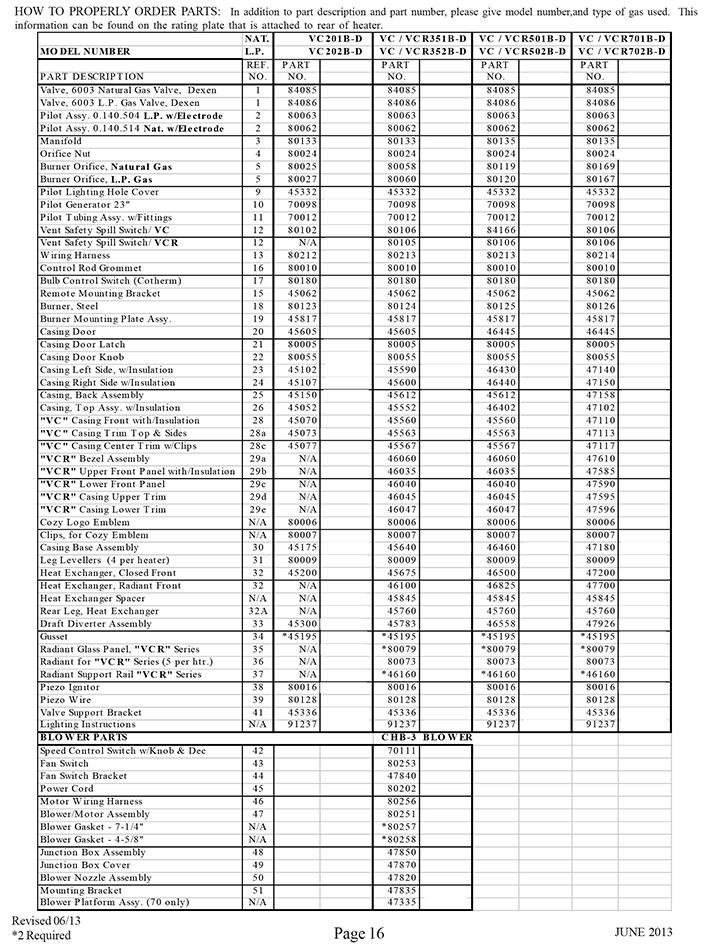
16
17 LIMITED WARRANTY Cozy Heating Systems LLC warrants to the original user the accompanying product for the period specified herein, provided said product is installed, operated, maintained, serviced, and used according to the instructions and specifications accompanying the product. AS OUTLINED IN OUR INSTRUCTIONS, ANY WARRANTY CONSIDERATIONS ARE CONTINGENT ON INSTALLATION BY A QUALIFIED INSTALLER (CONTRACTOR). SELF-INSTALLATION IS PROHIBITED AND WILL INVALIDATE YOUR WARRANTY. If within a period of one year from the date of installation of the product, any part supplied by the manufacturer proves to be defective due to workmanship or material, it will replace such part, provided parts have not been subjected to misuse, alteration, neglect, or accidents. The term of the warranty for the heat exchanger and burners is covered in Table A below. Any claim not made within ten (10) days after the expiration of the warranty period shall be deemed waived by the user. The manufacturer shall have no liability or be required to perform any obligation under this warranty unless, when requested, the user returns, at the user s expense, the component or product claimed defective, to the manufacturer for inspection, to enable the manufacturer to determine if the claimed defect is covered by this warranty. No charges for freight, labor or other expenses incurred in the repair, removal, or replacement of any product or component claimed to be defective, will be paid by the manufacturer to the user, and the manufacturer will not be liable for any expenses incurred, by the user, in remedying any defect in the product. Service under this warranty is the responsibility of the installer. In the event service TABLE A under this warranty is needed, the user of the product shall request such service directly from the installer. If the user is unable to locate the installer, the user should write directly to the manufacturer, and the name of an alternative service source will be supplied. The product safety registration card (packed inside the appliance) must be completed and returned to the factory. THIS WARRANTY IS EXPRESSLY IN LIEU OF ANY OTHER WARRANTIES, EXPRESS OR IMPLIED (WHETHER WRITTEN OR ORAL). ANY IMPLIED WARRANTY OF MERCHANTABILITY OR OF FITNESS FOR A PARTICULAR PURPOSE IS EXPRESSLY LIMITED TO THE DURATION OF THE MANUFACTURER S EXPRESS, WRITTEN WARRANTY. UNDER NO CIRCUMSTANCES SHALL THE MANUFACTURER BE LIABLE FOR ANY SPECIAL, INDIRECT OR CONSEQUENTIAL DAMAGES OR EXPENSES ARISING DIRECTLY OR INDIRECTLY FROM ANY COMPONENT OR FROM THE USE THEREOF. THE REMEDIES SET FORTH HEREIN SHALL BE THE EXCLUSIVE REMEDIES AVAILABLE TO THE USER AND ARE IN LIEU OF ALL OTHER REMEDIES. SOME STATES DO NOT ALLOW LIMITATIONS ON HOW LONG AN IMPLIED WARRANTY LASTS, SO THE ABOVE LIMITATIONS MAY NOT APPLY TO YOU. SOME STATES DO NOT ALLOW THE EXCLUSION OR LIMITATION OF INCIDENTAL OR CONSEQUENTIAL DAMAGES, SO THE ABOVE LIMITATIONS OR EXCLUSIONS MAY NOT APPLY TO YOU. THIS WARRANTY GIVES YOU SPECIFIC LEGAL RIGHTS, AND YOU MAY ALSO HAVE OTHER RIGHTS, WHICH VARY, FROM STATE TO STATE. Warranty Period Product Heat Exchanger/Tubes Burners Cozy Gas Fired Floor Furnace 10 Years 10 Years Cozy Gas Fired Wall Furnace 10 Years 10 Years Cozy Gas Fired Vented Console Heater 10 Years 10 Years Cozy Gas Fired Direct Vent Heater 10 Years 10 Years Cozy Gas Fired Counterflow Furnace 10 Years 10 Years Cozy Gas Fired Counterflow Direct Vent Furnace 10 Years 10 Years Cozy Gas Fired Mobile Home Direct Vent Furnace 10 Years 10 Years Cozy Gas Fired Hi-Efficient Direct Vent Wall Furnace 10 Years 10 Years Cozy Gas Fired Direct Vent Baseboard Heater 10 Years 10 Years Cozy Fan-Type, Direct Vent Through-The-Wall Gas Heater 10 Years 10 Years Cozy Blue Flame Vent Free Heater N/A 10 Years Cozy Infra-Red Vent Free Heater N/A N/A COZY HEATING SYSTEMS LLC 3230 INDUSTRIAL PARKWAY. JEFFERSONVILLE, IN 47130
Gas-Fired Vented Room Heater
 Gas-Fired Vented Room Heater R INSTALLATION AND OPERATING INSTRUCTIONS P/N 80900 - REV. 12/03 R NATURAL GAS VC201A VC351A VC501A VC701A VCR351A VCR501A VCR701A PROPANE GAS VC202A VC352A VC502A VC702A VCR352A
GAS-FIRED VENTED WALL FURNACE
 R GAS-FIRED VENTED WALL FURNACE INSTALLATION AND OPERATING INSTRUCTIONS P/N 84502 / REV. 03/19/2013 R NATURAL GAS W255F, W355F, W505F L.P. GAS W256F, W356F, W506F WARNING: If the information in this manual
INSTALLATION OPERATING, AND SERVICE INSTRUCTIONS FOR SUBURBAN DIRECT VENT SEALED COMBUSTION GAS HEATER MODEL GT-10D
 INSTALLATION OPERATING, AND SERVICE INSTRUCTIONS FOR SUBURBAN DIRECT VENT SEALED COMBUSTION GAS HEATER MODEL GT-10D FOR YOUR SAFETY FOR YOUR SAFETY IF YOU SMELL GAS: DO NOT STORE OR USE GASOLINE 1. OPEN
MODELS LFP4218/LFP6018 TOP VENT GAS FIREPLACE
 MODELS LFP4218/LFP6018 TOP VENT GAS FIREPLACE PFS APPROVED FOR NATURAL GAS OR PROPANE GAS Z21.50-2014 If your plans do not allow for the venting system as outlined previously in the installing chimney/vent
DIRECT VENT WALL FURNACE
 DIRECT VENT WALL FURNACE R INSTALLATION AND OPERATING INSTRUCTIONS P/N 70905 REV. 10/2010 MODEL NUMBERS NATURAL GAS CDV155B CDV255B CDV335B L.P. GAS CDV156B CDV256B CDV336B R WARNING: If the information
Owner s Guide Installation & Operation
 Owner s Guide Installation & Operation Hot Top HHT Series Hestan Commercial Corporation 3375 E. La Palma Ave Anaheim, CA 92806 (888) 905-7463 RETAIN THIS MANUAL FOR FUTURE REFERENCE P/N 002130 REV 1 IMPORTANT
INFRARED RADIANT HEATER RSCA SERIES CERAMIC HEATERS NATURAL GAS PROPANE GAS DATE: PROJECT: ARCHITECT/ENGINEER: CONTRACTOR: SUBMITTED BY:
 INFRARED RADIANT HEATER RSCA SERIES CERAMIC HEATERS NATURAL GAS (CHECK ONE) PROPANE GAS PROJECT: ARCHITECT/ENGINEER: NAME: ADDRESS: NAME: ADDRESS: DATE: CONTRACTOR: SUBMITTED BY: NAME: ADDRESS: EQUIPMENT
CYLINDER NOT INCLUDED
 OPERATING INSTRUCTIONS AND OWNER S MANUAL Model # HS125NG / MH125LP / HS125LP READ INSTRUCTIONS CAREFULLY: Read and follow all instructions. Place instructions in a safe place for future reference. Do
Installation Instructions T 9822 Gas Dryer. en - US, CA. To prevent accidents
 Installation Instructions T 9822 Gas Dryer To prevent accidents en - US, CA and appliance damage read these instructions before installation or use. M.-Nr. 07 431 110 2 WARNING For your safety the information
USER S INFORMATION MANUAL
 USER S INFORMATION MANUAL UPFLOW/HORIZONTAL & DOWNFLOW TWO STAGE INDUCED DRAFT GAS FURNACES Recognize this symbol as an indication of Important Safety Information If the information in this manual is not
GAS -FIRED VENTED ROOM HEATERS MODEL 61TV
 GAS -FIRED VENTED ROOM HEATERS MODEL 61TV INSTALLATION MANUAL NEW BUCK CORPORATION WARNING: Improper installation, adjustment, alteration,service or maintenance can cause injury or property damage. Refer
USER S INFORMATION MANUAL
 USER S INFORMATION MANUAL UPFLOW & DOWNFLOW/HORIZONTAL CONDENSING GAS FURNACES SAFETY Recognize this symbol as an indication of Important Safety Information If not installed, operated and maintained in
GAS COOKTOP INSTALLATION INSTRUCTIONS
 INSTALLATION AND SERVICE MUST BE PERFORMED BY A QUALIFIED INSTALLER. IMPORTANT: SAVE FOR LOCAL ELECTRICAL INSPECTOR'S USE. READ AND SAVE THESE INSTRUCTIONS FOR FUTURE REFERENCE. WARNING If the information
USER S INFORMATION MANUAL
 USER S INFORMATION MANUAL UPFLOW, DOWNFLOW, UPFLOW/HORIZONTAL & HORIZONTAL ONLY INDUCED DRAFT GAS FURNACES Recognize this symbol as an indication of Important Safety Information If the information in this
INSTALLATION AND OPERATION MANUAL GAS SKILLETS MODELS: GTS-30 GTS-40
 INSTALLATION AND OPERATION MANUAL GAS SKILLETS MODELS: GTS-30 GTS-40 CROWN FOOD SERVICE EQUIPMENT LTD. 70 OAKDALE ROAD, DOWNSVIEW, (TORONTO), ONTARIO, CANADA, M3N 1V9 TELEPHONE: (416) 746-2358, FAX: (416)
VENTING CLEARANCES. BBT NORTH AMERICA Bosch Group. Bosch Water Heating 340 Mad River Park, Waitsfield, VT TWH-V-26 page 1 of 6 rev 01/06
 page 1 of 6 VENTING CLEARANCES The vents should not be obstructed and all joints properly fitted. Floors, ceilings and walls must be cut or framed to provide necessary clearance to vents. Metal strippings
Installer: Leave this manual with the appliance. Consumer: Retain this manual for future reference.
 Installer: Leave this manual with the appliance. Consumer: Retain this manual for future reference. Operating Instructions and Owner s Manual READ INSTRUCTIONS CAREFULLY: Read and follow all instructions.
INSTALLATION OPERATION AND SERVICE MANUAL
 INSTALLATION OPERATION AND SERVICE MANUAL THE OLD SALEM COLLECTION VENT FREE REGENCY COAL BASKET complies with ANSI Z21.11.2 THIS ONLINE MANUAL IS FOR PLANNING PUPOSES ONLY. CAREFULLY READ BEFORE PURCHASING.
Models #CSK-31 #CSK-31-RF. CHASKA Direct Vent Gas Fireplace Insert INSTALLATION & OPERATING MANUAL
 WARNING: If the information in these instructions are not followed exactly, a fire or explosion may result causing property damage, personal injury or loss of life. Models #CSK-31 #CSK-31-RF CHASKA Direct
Owner s Guide Installation & Operation
 Owner s Guide Installation & Operation Char Broiler HCH Series Hestan Commercial Corporation 3375 E. La Palma Ave Anaheim, CA 92806 (888) 905-7463 RETAIN THIS MANUAL FOR FUTURE REFERENCE P/N 002134 REV
Legend VENTED GAS FIREPLACE HEATERS
 MODEL 937XN FOR USE WITH NATURAL GAS Legend MODEL 937XP FOR USE WITH PROPANE VENTED GAS FIREPLACE HEATERS WARNING: If the information in this manual is not followed exactly, a fire or explosion may result
CATALINA FIRE TABLE ASSEMBLY INSTRUCTIONS
 CATALINA FIRE TABLE ASSEMBLY INSTRUCTIONS CSA Model 98300 DRF01000 Installer: Leave these instructions with consumer. Consumer: Keep these instructions for future reference. DANGER If you smell gas: 1.
Vented Room Heaters ENCLOSED MODEL FIREPLACE MODEL. Williams Furnace Co. 250 West Laurel Street Colton, California U.S.A.
 Save this manual for future reference. Vented Room Heaters Model Numbers: 2001622A; 2011622A; 2031622A; 2051622A; 3501522A; 3511522A; 3531522A; 3551522A; 3501922A; 3511922A; 3531922A; 3551922A; 3502522A;
Models #CSK-335 #CSK-335-RF. CHASKA - XL Direct Vent Gas Fireplace Insert INSTALLATION & OPERATING MANUAL
 WARNING: If the information in these instructions are not followed exactly, a fire or explosion may result causing property damage, personal injury or loss of life. Models #CSK-335 #CSK-335-RF CHASKA -
OVATION SERIES FIRE TABLES ASSEMBLY INSTRUCTIONS
 OVATION SERIES FIRE TABLES ASSEMBLY INSTRUCTIONS CSA Model98900 DRS02403 Installer: Leave these instructions with consumer. Consumer: Keep these instructions for future reference. DANGER If you smell gas:
Installation/Operating Instructions
 Installation/Operating Instructions Models: 4072-180 24 NG 4072-182 30 NG Outdoor Hearth Kit DO NOT DISCARD INSTALLER: Leave this manual with party responsible for use and operation. OWNER: Retain this
Owner s Manual. Blue Flame Unvented Gas Heater. 20,000 Btu/hr. Model. 6,000 and 10,000. Btu/hr. Model
 Owner s Manual Save this manual for future reference. Blue Flame Unvented Gas Heater 6,000 and 10,000 Btu/hr. Model 20,000 Btu/hr. Model Model Numbers: 0656542.9; 1056512.9; 1056542.9, 2056512.9; 3056512.9
SIERRA RADIANT HEAT MAJESTIC OAK VENTED GAS LOG KIT INSTALLATION AND OPERATING INSTRUCTIONS
 SIERRA RADIANT HEAT MAJESTIC OAK VENTED GAS LOG KIT INSTALLATION AND OPERATING INSTRUCTIONS WARNING: If the information in this manual is not followed exactly, a fire or explosion may result causing property
ASSEMBLY INSTRUCTIONS
 ASSEMBLY INSTRUCTIONS Installer: Leave these instructions with consumer. Consumer: Keep these instructions for future reference. WARNING: If the information in this manual is not followed exactly, a fire
Installation and service must be provided by a qualified installer, service agency or the gas supplier.
 INSTALLATION AND OPERATION GUIDE FOR OLDE WORLD BASKET Vented Decorative Appliance For all models tested through PFS Corporation, to ANSI Z21.60-2003/CGA 2.26-2003, Decorative Appliance for Installation
HI-EFFICIENT DIRECT VENT WALL FURNACE INSTALLATION AND OPERATING INSTRUCTIONS P/N / JUNE 2015
 HI-EFFICIENT DIRECT VENT WALL FURNACE INSTALLATION AND OPERATING INSTRUCTIONS P/N 72903 / JUNE 2015 MODEL NUMBERS NAT. GAS HEDV253A HEDV403A L.P. GAS HEDV254A HEDV404A INSTALLER: Leave this manual with
ASSEMBLY INSTRUCTIONS
 ASSEMBLY INSTRUCTIONS CSA Model: 98910L Printed in China Installer: Leave these instructions with consumer. Consumer: Keep these instructions for future reference. WARNING: If the information in this manual
Repeat procedures for other side.
 Repeat procedures for other side. ASSEMBLY INSTRUCTIONS Installer: Leave these instructions with consumer. Consumer: Keep these instructions for future reference. CSA Model 98900 Printed in China DANGER
Owner s Manual. Gravity Vented Floor Furnace
 Owner s Manual Save this manual for future reference. Gravity Vented Floor Furnace Model Numbers: 4505622A; 6005622A FOR USE WITH NATURAL GAS ONLY Model Numbers: 4505621A; 6005621A FOR USE WITH PROPANE
UVST (SMOOTH FACE) UVCST (HEAT CIRCULATING) INSTALLATION & OPERATING INSTRUCTIONS
 UVCST (HEAT CIRCULATING) INSTALLATION & OPERATING INSTRUCTIONS") UNIVERSAL VENTFREE FIREPLACE UVST (SMOOTH FACE) UVCST (HEAT CIRCULATING) INSTALLATION & OPERATING INSTRUCTIONS 36 DUAL-SIDED FIREPLACE TO BE USED WITH ANY APPROVED VENTFREE GAS LOGS SAVE THIS BOOK This
UNIVERSAL VENTFREE FIREPLACE UVST (SMOOTH FACE) UVCST (HEAT CIRCULATING) INSTALLATION & OPERATING INSTRUCTIONS 36 DUAL-SIDED FIREPLACE TO BE USED WITH ANY APPROVED VENTFREE GAS LOGS SAVE THIS BOOK This
INSTALLATION GUIDE Dual Fuel Ranges
 INSTALLATION GUIDE Dual Fuel Ranges Contents Wolf Dual Fuel Ranges......................... 3 Safety Instructions............................ 4 Dual Fuel Range Specifications.................. 5 Dual Fuel
CINCINNATI, OH USA
 INSTRUCTION MANUAL Part No. 89731 Revised October 1997 CINCINNATI, OH 45241-4807 USA GAS SAFETY PRECAUTIONS Instructions on what to do when a user smells gas can be obtained from the local gas supplier.
Model RGAC/SGAC Self Contained Cooling/Gas Heat MODELS RGAC & SGAC - R22 USER'S INFORMATION, MAINTENANCE AND SERVICE MANUAL
 Model RGAC/SGAC Self Contained Cooling/Gas Heat Supersedes: 145.24-O1 (708) Units Form 145.24-O1 (908) MODELS RGAC & SGAC - R22 USER'S INFORMATION, MAINTENANCE AND SERVICE MANUAL CATEGORY III GAS HEATING/ELECTRIC
MAN AUTO IMPORTANT INSTRUCTIONS PLEASE READ THIS MANUAL BEFORE INSTALLING AND USING APPLIANCE
 Wall Heater Fan MODEL #: 2275 This fan is a CSA approved component compatible with these Williams wall heaters only: 1076512.9 2076512.9 3076512.9 1276512 1876512 3076512 1076511.9 2076511.9 IMPORTANT
INSTALLATION INSTRUCTIONS AND OWNER S MANUAL VENTED ROOM HEATER MODELS RH-25-6 RH-35-6 EFFECTIVE DATE SEPTEMBER 2003
 INSTALLATION INSTRUCTIONS AND OWNER S MANUAL VENTED ROOM HEATER MODELS RH-25-6 RH-35-6 WARNING: If the information in this manual is not followed exactly, a fire or explosion may result causing property
SURE HEAT MANUFACTURING
 SURE HEAT MANUFACTURING Installation and Operating Instructions for NATURAL & L.P. GAS A.G.A. SINGLE & DUAL BURNER VENTED UNITS Model: RP (8,24,30)-N GO (8,24,30)-N GLO (8,24,30)-N WO (8,24,30)-N CO (8,24,30)-N
INSTALLATION, OPERATION & MAINTENANCE AVANTCO SERIES 177AG OWNER S MANUAL
 INSTALLATION, OPERATION & MAINTENANCE AVANTCO SERIES 177AG OWNER S MANUAL Manual Griddles: Radiant Charbroilers: Hot Plates: 177AG24MG 177AG36MG 177AG24RC 177AG36RC 177AGR212 All equipment manufactured
INSTALLATION AND OPERATION INSTRUCTIONS
 Printed in U.S.A. INSTALLATION AND OPERATION INSTRUCTIONS RFPA21A CONSTRUCTION HEATER FLOOR MODEL SAVE FOR FUTURE REFERENCE Space-Ray Division, Gas Fired Products, Inc. P.O. Box 36485, Charlotte, NC 28236
Internet Version for Reference Only INDUCED DRAFT COMMERCIAL WATER HEATERS SUPPLEMENT INSTRUCTIONS TO PART #
 INDUCED DRAFT COMMERCIAL WATER HEATERS SUPPLEMENT INSTRUCTIONS TO PART #238-39387-00 THIS INSTRUCTION SUPPLEMENT IS ONLY INTENDED TO GIVE INSTALLATION INSTRUCTIONS AND INFORMATION RELATED TO THE INDUCED
ASSEMBLY INSTRUCTIONS
 ASSEMBLY INSTRUCTIONS Installer: Leave these instructions with consumer. Consumer: Keep these instructions for future reference. CSA Model99000 BRH01000 DANGER If you smell gas: 1. Shut off gas to the
V SERIES HDR GAS RANGES
 SERVICE MANUAL ONE POWERFUL PACKAGE V SERIES HDR GAS RANGES TOPS Open Top Hot Top Griddle Top Work Surface BASES Standard Oven Convection Oven Cabinet Base - NOTICE - This manual is prepared for use by
Using it in an enclosed space can kill you.
 38 X 56 GAS FIRE PIT - OWNER S MANUAL Carlisle Chat Fire Table Base Model # 00GBC7 (6877B) Fits 6877A Carlisle Chat Fire Table Top For Propane and *Natural Gas (*See Page 7) Certified to CSA International
INSTALLATION AND OPERATING INSTRUCTIONS
 INSTALLER/CONSUMER RETAIN THIS APPLIANCE MANUAL WITH THE INSTALLED APPLIANCE INSTALLATION AND OPERATING INSTRUCTIONS GOLDEN BLOUNT TOP-VENT FIREPLACES MODEL HD5030-TV EL GRANDE HD4240-TV SKYSCRAPER PFS
Hanover Outdoor Furniture IMPORTANT. If you have any problems with this product (missing or damaged parts, assembly issues, etc.),
,") Hanover Outdoor Furniture IMPORTANT If you have any problems with this product (missing or damaged parts, assembly issues, etc.), PLEASE DO NOT RETURN TO THE RETAILER/STORE from where you purchased the
Hanover Outdoor Furniture IMPORTANT If you have any problems with this product (missing or damaged parts, assembly issues, etc.), PLEASE DO NOT RETURN TO THE RETAILER/STORE from where you purchased the
OPERATING INSTRUCTIONS AND OWNER S MANUAL
 OPERATING INSTRUCTIONS AND OWNER S MANUAL MR. HEATER READ INSTRUCTIONS CAREFULLY: Read and follow all instructions. Place instructions in a safe place for future reference. Do not allow anyone who has
S150 S300 CONSTRUCTION HEATERS. Rev: August 15, 2008 SERVICE AND MAINTENANCE MANUAL No PLEASE RETAIN FOR FUTURE REFERENCE PRODUCTS
 S150 & S300 CONSTRUCTION HEATERS Rev: 2.7.2 August 15, 2008 SERVICE AND MAINTENANCE MANUAL No. 934-6637 PLEASE RETAIN FOR FUTURE REFERENCE PRODUCTS A DIVISION OF HAUL-ALL EQUIPMENT LTD. 4115-18 Avenue
ASSEMBLY INSTRUCTIONS
 ASSEMBLY INSTRUCTIONS CSA Model 99000 ARL00100 Installer: Leave these instructions with consumer. Consumer: Keep these instructions for future reference. DANGER If you smell gas: 1. Shut off gas to the
INSTALLATION INSTRUCTIONS AND OWNER S MANUAL
 INSTALLATION INSTRUCTIONS AND OWNER S MANUAL VENTED ROOM HEATER MODELS RH-50-6 RH-50C-1 RH-65-6 RH-65C-1 RH-50-6 Shown WARNING: If the information in these instructions are not followed exactly, a fire
Installation instructions for the T 9820 Gas Dryer
 Installation instructions for the T 9820 Gas Dryer The T 9820 gas dryer is only approved for use in the USA and Canada. It is not approved for use in Mexico. To prevent accidents en - US, CA and machine
#CSK-31-RF. CHASKA Direct Vent Gas Fireplace Insert INSTALLATION & OPERATING MANUAL
 Models #CSK-31 #CSK-31-RF CHASKA Direct Vent Gas Fireplace Insert INSTALLATION & OPERATING MANUAL WARNING: If the information in these instructions is not followed exactly, a fire or explosion may result,
Stoneridge Fire Pit High Dining Table Assembly Instruction
 Stoneridge Fire Pit High Dining Table Assembly Instruction Item# L-DN1773SST-D-T WARNING: For Outdoor Use Only. DANGER If you smell gas: 1. Shut off gas to the appliance. 2. Extinguish any open flame.
INSTALLATION OPERATION AND SERVICE MANUAL
 INSTALLATION OPERATION AND SERVICE MANUAL VENTED DECORATIVE GAS APPLIANCE/ DECORATIVE COAL/LOG SET B30/B31/B32/B33/B34 PLEASE READ THIS MANUAL CAREFULLY BEFORE INSTALLING AND OPERATING THE APPLIANCE. ALWAYS
CARBON MONOXIDE HAZARD. This appliance can produce carbon monoxide which has no odor. Using it in an enclosed space can kill you.
 Intrigue EZ User manual for Intrigue EZ decorative gas appliance CAUTION DO NOT DISCARD THIS MANUAL Important operating and maintenance instructions included. Read, understand, and follow these instructions
PAULIN PRODUCTS INDOOR HEATER
 PAULIN PRODUCTS INDOOR HEATER OWNER S MANUAL AND OPERATING INSTRUCTIONS May be used with a disposable 1 lb. propane cylinder: - for emergency indoor home heating - for indoor use in commercial enclosures,
ZG Shown READ ALL INSTRUCTIONS IN THIS MANUAL AND RETAIN FOR FUTURE REFERENCE WARNING
 See unit nameplate for manufacturer and address. 507258-04 7/2018 Supersedes 10/2017 ZG 036, 048, 060, 072, 074 (3, 4, 5 and 6 Tons) ZG 092, 102, 120, 150 (7-1/2, 8-1/2, 10 and 12 Tons) ROOFTOP UNITS ZG
Installation Instructions
 Installation Instructions Gas & Electric Dryer Before beginning installation, carefully read these instructions. This will simplify the installation and ensure the dryer is installed correctly and safely.
WHAT TO DO IF YOU SMELL GAS
 AHE AHE SERIES 4 Direct Vent Wall-Mounted Boilers User s Information Manual If the information in this manual is not followed exactly, a fire or explosion may result, causing property damage, personal
USER S INFORMATION MANUAL
 USER S INFORMATION MANUAL HOT WATER HEATING BOILERS DOMESTIC WATER HEATERS 150,000-300,000 Btu/hr MODELS EB-EWU-02 IMPORTANT INSTALLER - AFFIX INSTALLATION MANUAL ADJACENT TO THE BOILER CONSUMER - RETAIN
WARNING FIRE OR EXPLOSION HAZARD.
 2017 Lennox Industries Inc. Dallas, Texas, USA 506897-01 04/2017 Supersedes 10/2015 EL280DF SERIES GAS FURNACE Improper installation, adjustment, alteration, service or maintenance can cause property damage,
INSTALLATION & OPERATING INSTRUCTION MANUAL Vented Room Heaters
 MODELS: NATURAL GAS ONLY 2001622; 2031622; 2051622 3501522; 3531522; 3551522 3501922; 3531922; 3551922 3502522; 3532522; 3552522 3502922; 3532922; 3552922 5001522; 5031522; 5051522 5001922; 5031922; 5051922
INSTALLATION & SERVICE MANUAL
 GAS-FIRED WATER HEATER If the information in these instructions is not followed exactly, a fire or explosion may result causing property damage, personal injury or death. INSTALLATION & SERVICE MANUAL
Construction Heater GENERAL HAZARD WARNING
 Dayton Operating Operating Instructions Instructions & Parts and Parts Manual Manual Model Dayton Natural Gas Construction Heater Please read and save these instructions. Read carefully before attempting
DAYVA PREMIERE OUTDOOR HEATER Model HS041-2
 INSTRUCTIONS DAYVA PREMIERE OUTDOOR HEATER Model HS041-2 By The Dayva Premier Outdoor heater is another fine product from Dayva International. Dayva is the leader in accessories for the outdoor market.
Mighty Venter Power Vent System
 Installation and Operation Instructions Document 7008B Installation and Operation Instructions for Mighty Venter Power Vent System Models MV2, MV3, MV4, and MV5 for Mighty Therm Sizes 500-1825 FOR YOUR
INSTALLATION & OPERATION MANUAL GAS CHARBROILERS
 INSTALLATION & OPERATION MANUAL GAS CHARBROILERS MODELS VCCB25 VCCB36 VCCB47 VCCB60 VCCB72 VCCB47 SCB25 SCB36 SCB47 SCB60 SCB72 SCB47 ITW Food Equipment Group, LLC 3600 North Point Blvd. Baltimore, MD
INSTALLATION AND OPERATION INSTRUCTIONS
 Printed in U.S.A. INSTALLATION AND OPERATION INSTRUCTIONS RCH100 CONSTRUCTION HEATER FLOOR MODEL WARNING IMPROPER INSTALLATION Improper installation, adjustment, alteration, service or maintenance can
Installation / Operation. Applies to: Standard Power Vent Unit Heaters: Separated Combustion Unit Heaters:
 Document No D300519 (4-8-16) Obsoletes Document No D300519 (04-15) Installation / Operation Applies to: Standard Power Vent Unit Heaters: Separated Combustion Unit Heaters: NOTE: Accessories referenced
INSTALLATION AND OPERATION GUIDE FOR HARGROVE VENT FREE GAS LOGS Element Series
 INSTALLATION AND OPERATION GUIDE FOR HARGROVE VENT FREE GAS LOGS Element Series DESIGN CERTIFIED to UNVENTED ANSI Z21.11 VENTED - ANSI Z21.60/CGA 2.26 Installation and service must be provided by a qualified
MODEL HS115-3, HS115-4 & HS115-5 WIRING DIAGRAM ADDENDUM
 TJERNLUND PRODUCTS, INC. 1601 Ninth Street White Bear Lake, MN 55110-6794 PHONE (800) 255-4208 (651) 426-2993 FAX (651) 426-9547 Visit our web site www.tjernlund.com MODEL HS115-3, HS115-4 & HS115-5 WIRING
DIRECT VENT GAS BASEBOARD HEATER
 DIRECT VENT GAS BASEBOARD HEATER INSTALLATION AND OPERATING INSTRUCTIONS R P/N 64900 / JANUARY 2011 MODEL NUMBERS INSTALLER: Leave this manual with the NAT. GAS L.P. GAS appliance. BBT53 BBT54 CONSUMER:
If the information in this manual is not followed exactly, a fire or explosion may result causing property damage, personal injury or death.
 Infinion C13 Installation and Operation Manual NOTICE TO INSTALLER Affix these instructions adjacent to the Infinion. NOTICE TO OWNER Keep these instructions for future reference. For additional information,
e Bath Fan with Light User s Guide
 e Bath Fan with Light User s Guide abfl100rnl, BFL125RNL Item Stock Number(s): BFL100RNL, BFL125RNL IMPORTANT INSTRUCTIONS - OPERATING MANUAL READ AND SAVE THESE INSTRUCTIONS READ CAREFULLY BEFORE ATTEMPTING
INSTALLATION AND OPERATING MANUAL
 WARNING: If the information in these instructions is not followed exactly, a fire or explosion may result, causing property damage, personal injury or loss of life. MODELS: #PRC-36 / #PRC-36-RF PRINCETON
TERRACE AND PATIO HEATER
 TERRACE AND PATIO HEATER USER INSTALLATION AND OPERATION GUIDE INDEX General and specifications.1,2 Security and caution.. 3 Tools and accessories required 5 Assembly instructions 5-7 Operation (Lighting
UNVENTED (VENT-FREE) BLUE FLAME GAS HEATER SAFETY INFORMATION AND INSTALLATION MANUAL
 BLUE FLAME GAS HEATER SAFETY INFORMATION AND INSTALLATION MANUAL") UNVENTED (VENT-FREE) BLUE FLAME GAS HEATER SAFETY INFORMATION AND INSTALLATION MANUAL MANUAL 10,000 BTU - 10542 AND 10543 THERMOSTAT 10,000 BTU - 10544 AND 10545 THERMOSTAT 20,000 BTU - 10546 AND 10547
UNVENTED (VENT-FREE) BLUE FLAME GAS HEATER SAFETY INFORMATION AND INSTALLATION MANUAL MANUAL 10,000 BTU - 10542 AND 10543 THERMOSTAT 10,000 BTU - 10544 AND 10545 THERMOSTAT 20,000 BTU - 10546 AND 10547
INSTALLATION & OPERATION MANUAL FOR Achiever Charbroilers
 INSTALLATION & OPERATION MANUAL FOR Achiever Charbroilers MODELS MLS VACB20 ML-135285 VACB25 ML-710543 VACB36 ML-710544 VACB47 ML-710545 VACB60 ML-710546 VACB72 ML-135286 www.vulcanhart.com MODELS MLS
TERRACE AND PATIO HEATER
 TERRACE AND PATIO HEATER USER INSTALLATION AND OPERATION GUIDE INDEX General and specifications.11 Security and caution.. 12, 13 Tools and accessories required 13 Assembly instructions 14,15 & 16 Verifying
LGB Gas fired boiler
 LGB Gas fired boiler Control Supplement LGB-5 Series 2 Propane gas CSD-1 Control System Part Number 550-110-682/0304 Please read this page first Hazard definitions To the installer... The following terms
CAUTION FOR YOUR SAFETY
 VENT-FREE GAS FIREBOX Model # PC32VFC & PC36VFC CAUTION FOR YOUR SAFETY WARNING: IF THE INFORMATION IN THIS MANUAL IS NOT FOLLOWED EXACTLY, A FIRE MAY RESULT CAUSING PROPERTY DAMAGE, PERSONAL INJURY, OR
Conversion Instructions Logano G234X. Gas boiler. Please read carefully before installing and servicing. Gas boiler
 Gas boiler UPON COMPLETION OF THE INSTALLATION THE INSTALLER MUST INSTRUCT THE OWNER AND OPERATOR ON THE FUNCTIONALITY AND THE PROPER OPERATION OF THE BOILER AND THE HEATING SYSTEM. INSTALLER MUST REVIEW
EDVRSPV47 EDVRSPV58. Warning: What to do if you smell gas
 Operation & Maintenance Manual Check local codes and read all instructions prior to installation. EDVRSPV BF-Series SS Roof Gas Power Fireplace Vent System f i r e f e a t u r e www.montigo.com EDVRSPV47
SAFE DRINKING WATER AND TOXIC ENFORCEMENT ACT
 Installation instructions for your new Spacemaker Laundry WSM2780 Gas Before you begin Read these instructions completely and carefully. IMPORTANT OBSERVE ALL GOVERNING CODES AND ORDINANCES. Note to Installer
Multi-Function Cooktop
 INSTALLATION GUIDE Multi-Function Cooktop Contents Wolf Multi-Function Cooktop.................... 3 Multi-Function Cooktop Specifications............ 4 Multi-Function Cooktop Installation...............
P.O. Box , Dallas, TX USER'S INFORMATION MANUAL Single-Stage Warm Air Gas Furnaces
 P.O. Box 799900, Dallas, TX 75379-9900 USER'S INFORMATION MANUAL Single-Stage Warm Air Gas Furnaces This is a safety alert symbol and should never be ignored. When you see this symbol on labels or in manuals,
INSTALLATION AND OPERATING MANUAL
 WARNING: If the information in these instructions is not followed exactly, a fire or explosion may result, causing property damage, personal injury or loss of life. MODEL: #56701 Thief River Falls - TRF
OPERATING INSTRUCTIONS MANUAL (Please retain for future reference) FVN/P-400 INDIRECT FIRED SPACE HEATERS
 FVN/P-400 INDIRECT FIRED SPACE HEATERS") OPERATING INSTRUCTIONS MANUAL (Please retain for future reference) For FVN/P-400 INDIRECT FIRED SPACE HEATERS CERTIFIED FOR USE IN CANADA AND U.S.A. As per Standard ANSI Z83.7/CSA 21.4 2000 Gas Fired Construction
OPERATING INSTRUCTIONS MANUAL (Please retain for future reference) For FVN/P-400 INDIRECT FIRED SPACE HEATERS CERTIFIED FOR USE IN CANADA AND U.S.A. As per Standard ANSI Z83.7/CSA 21.4 2000 Gas Fired Construction
USER S INFORMATION MANUAL
 2005 Lennox Industries Inc. Dallas, Texas, USA USER S INFORMATION MANUAL 13GCSX SERIES UNITS GAS PACKAGED UNITS (2 5 TONS) Armstrong # 38152A068 505,058M 05/09 Supersedes 08/05 Table of Contents Litho
e Bath Fan with Light User s Guide
 e Bath Fan with Light User s Guide abfl125rok Item Stock Number(s): BFL125ROK IMPORTANT INSTRUCTIONS - OPERATING MANUAL READ AND SAVE THESE INSTRUCTIONS READ CAREFULLY BEFORE ATTEMPTING TO ASSEMBLE, INSTALL,
Integrated Ventilation System
 Integrated Ventilation System For use with models: IVS1, IVSR1, IVS2, IVSR2 Installation Instructions Part No. 65278 Rev. K Table of Contents Important Safety Instructions... 1 Important Information About
southbend A MIDDLEBY COMPANY INSTALLATION AND OPERATION MANUAL CG214 (E) CG314 (E) CG414 (E) CG220 (E) CG320 (E) CG325 (E) GAS BOILERS MODELS:
 CG314 (E) CG414 (E) CG220 (E) CG320 (E) CG325 (E) GAS BOILERS MODELS:") INSTALLATION AND OPERATION MANUAL GAS BOILERS MODELS: CG214 (E) CG314 (E) CG414 (E) CG220 (E) CG320 (E) CG325 (E) southbend A MIDDLEBY COMPANY 1100 Old Honeycutt Road Fuquay-Varina, NC 27526 (919) 552-9161
INSTALLATION AND OPERATION MANUAL GAS BOILERS MODELS: CG214 (E) CG314 (E) CG414 (E) CG220 (E) CG320 (E) CG325 (E) southbend A MIDDLEBY COMPANY 1100 Old Honeycutt Road Fuquay-Varina, NC 27526 (919) 552-9161
Owner s Manual. Top-Vent Gravity Wall Furnace
 Owner s Manual Save this manual for future reference. Top-Vent Gravity Wall Furnace Model Numbers: 2509622; 2539622; 2559622; 3509622; 3539622; 3559622; 5009622; 5039622; 5059622 FOR USE WITH NATURAL GAS
STAR-MAX GAS GRIDDLES MODELS 615MA 624MA 636MA 648MA 615TA 624TA 636TA 648TA 624TSPA 636TSPA 648TSPA
 Star Manufacturing International Inc. 10 Sunnen Drive St. Louis, MO 63143 Phone: (314) 781-2777 Fax: (314) 781-3636 Installation and Operating Instructions 2M-Z1351 Rev. B 4/23/04 STAR-MAX GAS GRIDDLES
INSTALLATION AND OPERATION INSTRUCTIONS
 Printed in U.S.A. INSTALLATION AND OPERATION INSTRUCTIONS RFPA10C CONSTRUCTION HEATER FLOOR MODEL SAVE FOR FUTURE REFERENCE Space-Ray Division, Gas Fired Products, Inc. P.O. Box 36485, Charlotte, NC 28236
VENT-FREE PROPANE GAS HEATER
 VENT-FREE PROPANE GAS HEATER OWNER S OPERATION AND INSTALLATION MANUAL Models: VP2000BA, VP2000BTA, and VP2800BTA WARNING: If the information in this manual is not followed exactly, a fire or explosion
Outdoor Flame Heater
 Model Outdoor Flame Heater Owner s Manual Read these instructions before lighting this appliance. DANGER If you smell gas: 1. Shut off gas to the appliance. 2. Extinguish any open flame. 3. If odor continues,