ORTAL Power Vent System Manual Table of Contents
|
|
|
- Stuart Richards
- 6 years ago
- Views:
Transcription


1 Ortal Power Vent System: Installation Manual
2 ORTAL Power Vent System Manual Table of Contents 1. Introduction 2 2. Safety Warnings 2 3. The ORTAL Power Vent System 3 a. Power Vent 4 b. Pathways and Fan Box 4 i. Venting Pathway 4 ii. Sealing 4 iii. Clearances 4 iv. Mounting 6 c. Pressure Switch 6 d. Parts List 7 4. Vent Connections and Adapters 8 5. Installing the ORTAL Power Vent System 10 a. Terminations 10 b. Restrictor Table ORTAL Power Vent System Diagram System Operation Technical Data 16 a. Fan Spec Sheet 17 b. Pressure Switch Diagram 18 c. System Diagram 19 d. Sketch of Power Vent system with Double Glass Troubleshooting Guide Appendix A M&G DuraVent Concentric Vent Ortal Power Vent System: Installation Manual 1
3 INTRODUCTION ORTAL Heating Solutions offers the best in aesthetic heating technology. ORTAL s Power Vent System is an optional accessory component to ORTAL s direct vent gas fireplace offerings. This unique fan blower system provides for increased flexibility of fireplace installation in homes and apartment buildings as well as in hospitality and commercial settings. Advantages of the ORTAL Power Vent System: Small diameter chimneys Longer venting pathways Options to run inlet and exhaust pathways horizontal, vertical and below the plane of the firebox. This Manual is for use with the installation of the ORTAL Power Vent System to be used along with ORTAL s fireplace installation manual. Other Power Vent and fan accessories may be available for use with ORTAL fireplaces. Consult those product manuals for proper installation and use. Vents other than the ORTAL Power Vent System are NOT covered in this manual. SAFETY WARNINGS and IMPORTANT INFORMATION WARNING Be sure to review all safety warnings and installation guidelines contained within this manual. WARNING Be sure to review all safety warnings and installation guidelines contained within ORTAL s fireplace installation manual. WARNING Electrical components. Be sure that all electrical connections are properly installed, insulated and secured to avoid potential ELECTRICAL SHOCK and FIRE HAZARD and malfunction of the system. Consult local building code requirements. Important It is imperative that all materials and objects used to carry out the installation are materials certified or specified by ORTAL Heating Solutions and are suitable for use. Do NOT install the system with different materials or objects than those approved for installation by ORTAL Heating Solutions. Important Exceeding the restrictions imposed by ORTAL Heating Solutions can cause damage to the function of the fireplace and/or to the living space in which the fireplace and vent system are installed. The installation must be carried out according to the instructions listed in this manual. ORTAL will not be responsible for any damage caused by improper installation. Ortal Power Vent System: Installation Manual 2
4 THE ORTAL POWER VENT SYSTEM The ORTAL Power Vent System can be affixed to any standard ORTAL fireplace using a vent adaptor. ORTAL fireplaces operate using direct vent technology. The Power Vent system is an optional accessory that can be used to enhance the fireplace and provide a variety of different installation configurations not available with typical direct vent pathways. The ORTAL Power Vent System application must be selected at the time of ordering the ORTAL fireplace unit. The type of venting is 3/5 ; this cannot be retro-fitted. Before installing the ORTAL Power Vent System, review the system s construction plan and design. Consider installation location and pathway(s) including any structural requirements, clearances for rough and finish materials and local codes. Ortal Power Vent System: Installation Manual 3
5 ORTAL Power Vent System: Basic Information Power Vent a. The Power Vent (also referred to as the fan or blower) is the mechanism which spins and creates a forceful draw on the exhaust air bringing in oxygen from the inlet pipe and forcing consumed carbon dioxide air out through the exhaust pathway. b. The fan box is placed in-line on the exhaust/inlet vent pathway. c. The Power Vent fan box shall be installed at a minimum 21 from the firebox connection point or a maximum 45 distance from the firebox. Venting Pathways a. Venting pathway of 3/5 will be by M&G Duravent. i. Air Inlet: 1. The pathway through which outside air is drawn into the firebox. ii. Exhaust Vent: 1. The pathway through which consumed air is expelled from the firebox and released to the outside of the building. 2. When leaving the firebox, the air (smoke) passing through and into the exhaust vent pipe is typically degrees celsius. b. Sealing and securing the venting pathways is critical to the optimal function of the fireplace and the Power Vent System and to prevent air from the living area from entering the firebox chamber and from consumed air being exported back into the living area. i. For the 3/5 pathway, 1. Make sure gasket in each gasket ring is complete 2. Each connection between chimney parts is twist locked 3. When removing or installing pipe, dot guides must be aligned ii. Depth/Angle of descent 1. The vent pipe can be installed up to 6 (vertical) below the bottom of the firebox frame (not including the legs). 2. Up to six 90 degree offsets or equal (i.e. 540 total degrees of offset/angles) are allowed. c. Clearances, Minimum clearance to combustible material: i. Power Vent Fan Box 1. Clearance Diagram below. Ortal Power Vent System: Installation Manual 4

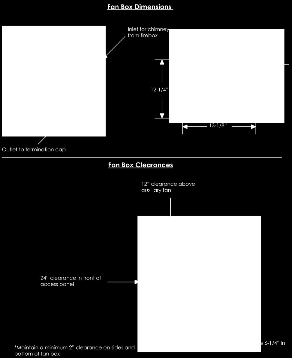
6 Ortal Power Vent System: Installation Manual 5
7 3. 2. Front cover of the box: 24 minimum (for service access) 3. Minimum 18x18 access panel required for service a. If it can be vented into the room, can have a louvered access door. Must maintain 150 sq. in. of free air within the access panel to cool the power vent fan components. b. If it can t be vented into the room, must be a closed access door and maintain 180 cubic ft. ii. Pathway: 3/5 Clearance 1. Between the firebox and the Power Vent fan Box a. Vertical run i. 1 radius b. Horizontal run i. Top (90 degrees), 3 ii. Bottom and sides (270 degrees), 1 2. From the Power Vent fan box to the termination cap a. Vertical run i. 1 radius b. Horizontal run i. Top (90 degrees), 3 ii. Bottom and sides (270 degrees), 1 3. Also, refer to ORTAL s fireplace installation manual for vent pipe clearance detail. iii. Make sure NO flammable materials are near the exhaust pipes as they may reach 400 degrees Celsius. d. Mounting i. Power Vent box and chimneys to be connected and secured per local code requirements. Pressure Switch a. This instrument identifies pressure. When the Power Vent fan is activated, the pressure switch senses the air flow and only then it transmits an electrical signal to the PV control module which then releases gas to the fireplace and allows it to operate. b. The pressure switch is a safety feature which prevents operation of a fireplace using the ORTAL Power Vent System without the fan being on or properly operating. Refer to System Operations and Sequence later in this manual for more details. Ortal Power Vent System: Installation Manual 6
8 4. ORTAL Power Vent System: Parts List Item Description Location Quantity 1 Power Vent Fan, PL20UL0080 Fan assembly 1 2 Power Vent Fan Box Fan assembly 1 3 Power Vent Fan Cover Fan assembly 1 4 Transformer and Receiver Fan assembly 1 5 Power Cord Fan assembly 1 6 Data Cord Fan assembly 1 7 Electronic Control Terminal (operated by Mertik Remote Control) Control Box (near fireplace) 8 Pressure Switch Control Box 1 9 Pressure Switch Tube Control Box 1 10 Data Termination Control Box 1 11 Receiver Termination Control Box 1 12 Gas Solenoid Between valve and burner 13 Gas Solenoid Termination Between valve and burner 14 Venting Adapters Comes with Series 40 to 80: Power Vent a. 4/6 to 3/5 System to Series 110 to 200: attach to b. 5/8 to 3/5 Firebox 15 Remote Control (or wall switch) and Receiver T16 Comes with Power Vent System Ortal Power Vent System: Installation Manual 7
9 ORTAL POWER VENT PIPE (35CVS) Part Number Description Pcs/ Ctn 35CVS-06 6" Pipe 6 35CVS-12 12" Pipe 6 35CVS-24 24" Pipe 6 35CVS-36 36" Pipe 6 35CVS-E45 45 Degree Elbow 6 35CVS-E90 90 Degree Elbow 6 35CVS-12TA 9"-12" Telescoping Adjustable Pipe 6 35CVS-18TA 12"-18" Telescoping Adjustable Pipe 6 35CVS-WS Wall Strap 12 35CVS-CD Universal Condensate Drain 1 35CVS-SC Storm Collar 1 35CVS-WT Wall Thimble 1 35CVS-FS Firestop Support 1 35CVS-F Adjustable Flashing 1 35CVS-HCR Horizontal Cap 1 35CVS-VC Vertical Cap 1 35CVS-RS Roof Support 1 VENT CONNECTIONS AND ADAPTERS 1. Sealing: In the ORTAL Power Vent System, the vents (pipes) must be sealed. Failure to seal the pathway(s) properly will prevent the system from working properly and can result in damage to the fireplace and/or the surrounding building. 2. Vents Pipe/Pathways: a. The ORTAL Power Vent System is certified for use with chimney pipe vent pathway from M&G DuraVent. This product was used during testing and certification of the ORTAL Power Vent System. While other similar products exist, they should not be substituted for the M&G DuraVent materials specified in this manual. b. Ensure that the pipes being used are intact and without flaw (i.e. no holes, tears, open seems, corrosion or other occurrences that may inhibit the proper function of the pipe with the Power Vent system.) c. Pipes must be installed using supports, minimum every 3 or per local code, the stricter of the two. Without proper support, the pathway may yield load upon the vent connection which can result in impairing the long-term sealant or other damage to the integrity of the sealed pathway. d. Secure all connections with self tapping stainless steal screws, minimum three for every connection point 3. Adaptors between the fireplace and vent: Adaptor components vary depending on the size/model of the fireplace. Adaptors will be provided with the Power Vent System. Confirm components are correct. Ortal Power Vent System: Installation Manual 8


10 Power Vent Adapters a. 35CVS PV Adapter b. 3 PV adapter c. 35CVS PV Adapter for Space Creator 120, 150, and 200 Ortal Power Vent System: Installation Manual 9
11 INSTALLING the ORTAL POWER VENT SYSTEM First, review the installation detail per project plans. Then, make sure all the materials, system components and tools necessary are present and in good condition. Now, installation can begin: 1. Build and install the rest of the air inlet/exhaust pathway(s). Ensure that all pipe pathway connections are sealed, supported and with clearances maintained as outlined previously in this manual. a. Pathways installation can be done before or after installation of the firebox and the rest of the Power Vent System. 2. Firebox installation. Recommended to place firebox in its final location first. However, Power Vent pathway and box can be installed before or after firebox. a. With firebox installation, place the Power Vent control system by the firebox access door. Make sure to place the control box with the arrow pointing up. b. Connect the vent adaptor firmly to the fireplace. Secure the vent adaptor with a minimum of 3 stainless steel screws and seal with hi-temp silicon. c. Connect the pressure switch to the pressure switch tube and secure. d. Connect the control box to the terminations as follows: i. Connect relay cable from Mertik GV60 receiver to termination #1 ii. Connect solenoid cable to termination #2 (it should already be installed in the flex tube line between the GV60 valve and the burner port). iii. Connect the data wire from the Power Vent fan box, the 6 volt communication cable between the control box and the Power Vent fan box, termination #3. Make sure the cable does not come in contact with the exhaust pipe. Refer to local building codes for cable insulation requirements, if any. 3. Place the fan box at its location and fasten in tightly maintaining required clearances and per local building codes. The fan box must be placed with at least 21 of exhaust pipe between the firebox and the fan box. (Depending on the way the pipe is laid, the fan box may be physically closer than 21.) 4. Pipe termination points a. At the termination points of exhaust and inlet pipes, caps must be affixed to prevent water from entering the pipes. i. For 3/5 use the 3/5 termination cap direct vent chimney pipe by M&G Duravent. Ortal Power Vent System: Installation Manual 10
12 ii. Use horizontal or roof termination part as end cap 5. Place the restrictor inside the firebox on the interior exhaust port and close with two bolts provided with the firebox (restrictor table below). 6. Connect the fireplace to the gas line. Gas connections to be done by a certified gas technician and in accordance with local building codes. 7. Connect the ORTAL Power Vent fan box to electricity. Electrical connections to be done by a certified electrician and in accordance with local building codes. Ortal Power Vent System: Installation Manual 11
13 RESTRICTOR TABLE Natural Gas (NG) Burner Restrictor # short route (x d) Restrictor # Long Route (x d) Max exhaust length (1.26 d) 34 (1.34 d) (1.34) 40 (1.57) (1.81) 48 (1.89) (1.89) 55 (2.16) (1.81) 55 (2.16) 76 Propane (LPG) Burner Restrictor # Restrictor # Max exhaust length short route (x d) Long Route (x d) (1.1 d) 30 (1.18 d) (1.1) 34 (1.34) (1.34) 40 (1.57) (1.57) 48 (1.89) (1.57) 48 (1.89) 99 Note: 1. Power Vent fan must be installed a minimum of 21 feet (linear vent length) from the firebox connection point and can be installed a maximum of 45 feet from the firebox. For special approval please contact ORTAL USA. Ortal Power Vent System: Installation Manual 12
14 ORTAL Power Vent System Diagram Ortal Power Vent System: Installation Manual 13

15 Ortal Power Vent System: Installation Manual 14
16 SYSTEM OPERATION Operation Instructions and Sequence 1. Use T16 remote control and receiver only. 2. An ORTAL fireplace equipped with Power Vent System is controlled the same way as a standard ORTAL fireplace. It is switched on/off the same way and flame control is the same. a. Refer to ORTAL fireplace manual and Mertik Maxitrol manual for more information. 3. When fan is connected to electricity, red LED light should be on in both the fan and control boxes. a. Red LED light indicates lives electricity is supplied to the fan system. 4. When igniting the fire with the remote control a white LED light turns on in both the fan and control boxes. a. The white LED light indicates that the PV system is given command to turn on. 5. When the fan begins to work, the pressure switch recognizes pressure in the exhaust pipe as compared to the air inlet as it is a closed system. The Power Vent System is verifying that the system is closed and active as a direct vent system. When a pressure threshold is passed (varies per fireplace model) the pressure switch will turn on a green LED light and send an electrical signal to the gas solenoid to open the gas between the GV60 valve and the burner port. a. The pilot flame is NOT part of the Power Vent System s electrical sub-system and works the same as with a standard ORTAL fireplace. Potential problems with the pilot have nothing to do with the Power Vent System. 6. Gas Solenoid a. When the solenoid opens, momentarily a blue LED light is lit in the control box. b. When the solenoid closes, momentarily a yellow LED light is lit in the control box. 7. The system operates with 110 volt 10 amps, no batteries, must have dedicated power line. If there is a power failure, the system will not operate. LED lights Color When Where Red Electricity is sent to fan. Fan and Control Boxes White PV system given command to turn on Fan and Control Boxes Green Air pressure threshold is passed Control Box Blue Solenoid open, gas released (burner on, pilot on) Control Box Ortal Power Vent System: Installation Manual 15

17 Yellow Solenoid closed, gas flow stopped (burner off, pilot on) Control Box Important - Before turning on the fireplace for the first time, ensure that the system is installed according to the above instructions; review the system sketches above and that all systems are connected properly. Important It is imperative, before turning on the fireplace for the first time, to review the instructions in the booklet concerning installation of the fireplace, and verify that the installation was done according to the instructions in this booklet. Also, if for any reason after installation, the fireplace does not work properly, the system must not in any way be turned on. When first turning on the fireplace, the pilot will switch on and only then will the rest of the burner ignite (as with the standard ORTAL fireplace). TECHNICAL DATA Ortal Power Vent System: Installation Manual 16
18 Ortal Power Vent System: Installation Manual 17

19 PRESSURE SWITCH DIAGRAM Ortal Power Vent System: Installation Manual 18
20 SYSTEM DIAGRAMS Ortal Power Vent System: Installation Manual 19
21 SKETCH FOR POWER VENT SYSTEM COMBINED WITH DOUBLE GLASS Ortal Power Vent System: Installation Manual 20
22 TROUBLESHOOTING GUIDE Important The fireplace and fan must be turned off at the first sign of any problem. Do NOT manipulate the system while the fireplace and the fan are turned on. Look for the appropriate solution. If the solution to the problem is ineffective, contact ORTAL. DESCRIPTIONS AND SOLUTIONS OF PROBLEMS PROBLEM SOLUTION 1. Pilot will not ignite The operation of the pilot is not connected to the operation of the Power Vent System. Consult your primary ORTAL fireplace manual or local ORTAL representative for troubleshooting guide. 2. The fan is noisy The blower is too tightly fastened to the box. Loosen the bolts. There is an issue with the blower fan. Look for defects or possible foreign objects or obstructions. 3. High or ghostly flames Confirm restrictor size. Adjust or change the restrictor. Refer to the restrictor table. Check connection to the exhaust pipe and confirm that it is sealed. If that does not resolve the issue, contact ORTAL. A restrictor other than what it is indicated in the table may be advised. 4. The pilot is on. The burner and Power Vent fan are not operating. The pressure switch does not recognize pressure in the vent and causing the gas solenoid to be closed. 1) Refer to LED table page No. 15. If a light that should be on is off, that is an indication of failure. 2) Confirm that control box is Ortal Power Vent System: Installation Manual 21
23 5. The pilot is on. The fan is on. The Burner is not operating. 6. The pilot is on. The burner is on. The fan is not operating. 7. The burner is on, but disengages without use of remote control (it goes off on its own). positioned level with arrow up. 3) Make sure the pressure switch is installed properly and connected to the pressure switch tube 4) Confirm that all terminations in control box are properly connected. 5) Look for obstruction 6) Check connection to the exhaust pipe. 7) Check the gas tube between the GV60 valve and the burner port. 8) Inlet pressure is too low or too high, not in the range required. Check with gas provider. Possible failure with the gas solenoid. Gas solenoid is not open, OR Wire (see termination #2) from control to gas solenoid is not connected, OR there is no proven draft. Definite failure with the gas solenoid. The system should shut down due to high CO level in the fireplace. If fireplace does not immediately shut down, manually turn the fireplace off. Confirm remote control is T16 model. A standard ORTAL (Mertik) remote control may activate the system, but it will not allow it to stay on. Confirm that the pilot is sealed and on. 8. The burner turns on and off Make sure the pressure switch is installed properly and connected to the pressure switch tube Important The fireplace and fan must be turned off at the first sign of any problem. Do NOT manipulate the system while the fireplace and the fan are turned on. Look for the appropriate solution. If the solution to the problem is ineffective, contact ORTAL. Ortal Power Vent System: Installation Manual 22

24 Installation Instructions Double wall / Direct Vent system for Pellet Fuel, Category II, III and IV condensing and non-condensing gas appliances. Concentric Stainless
25 NOTE: Examine all components for possible shipping damage prior to installation. Proper joint assembly is essential for a safe installation. Follow these instructions exactly as written. Check the integrity of all joints upon completion of assembly. This venting system must be free to expand and contract. This venting system must be supported in accordance with these instructions. Check for unrestricted vent movement through walls, ceilings, and roof penetrations. Different manufacturers have different joint systems and adhesives. Do not mix pipe, fittings, or joining methods from different manufacturers. NOTE: Read through all of these instructions before beginning your installation. Failure to install as described in this instruction will void the manufacturer s warranty, and may have an effect on your homeowner s insurance and UL listing status. Keep these instructions for future reference. This booklet also contains instructions for installing a venting system within an existing masonry chimney, and for installations passing through a cathedral ceiling. Dear Customer, Installer, or End User: We welcome any comments, ideas, input or compliants regarding matters pertaining to our DuraVent products. If you are searching for tech support or product information, please phone us at Or us at: techsupport@duravent.com LISTED MH25700, MH8381, MH14420, CMH1439, CMH1440
26 FasNSeal Concentric Vent Installation Instructions For the most up-to-date installation instructions, see CONTENTS Applications, Clearances, Permits, Equipment & Materials, General Notes.4 Joint Connections Appliance Connection, Condensate Drains, Installation, Horizontal Installations Vertical Installations Maintenance Warranty Concentric stainless 3
27 APPLICATIONS M&G DuraVent s Concentric Stainless (CVS) vent pipe is listed to UL1738 as a double-wall vent system for Category II, III, and IV gas appliances, to UL641 and ULC/ORD C441 for pellet fuel, and ULC S609 for L Vent. CVS is pressure rated to 10 in-w.c. for the inner pipe. CVS can also be used as a direct vent system, where the inner pipe is the exhaust vent; the outer pipe supplies the combustion air for the appliance. When installing CVS with direct vent appliances, the vent is considered a component of the appliance, and is listed in conjunction with the appliance to the corresponding appliance standard. Check with your appliance manufacturer or look in the appliance installation instructions to verify that M&G DuraVent s CVS has been listed as a direct vent for use with your appliance. CLEARANCES CVS is listed to 0" clearance as a doublewall vent system for Category II, III, and IV appliances, for flue temperature of up to 400-degrees F for horizontal enclosures, and up to 480-degrees F for vertical enclosures. CVS must maintain 1" clearance to combustibles when used with pellet fuel. When CVS is used as a concentric/direct vent system on gas, the clearance to combustibles are specified by the appliance manufacturer. Check with your appliance manufacturer for specifications about clearance to combustibles for the vent pipe, which may vary from one appliance to another. Never fill any required clearance space with insulation or any other materials. Combustible materials include, but are not limited to, lumber, plywood, sheetrock, plaster and lath, furniture, curtains, electrical wiring, and building insulation. PERMITS Before installation, check with your local Building Official, Fire Official, or other authority having jurisdiction regarding permits, restrictions, and installation inspections in your area. GENERAL INSTALLATION NOTES Read through these installation instructions before beginning your installation. Proper planning for your Concentric Stainless Vent system installation will result in greater safety, efficiency, and convenience, as well as saving time and money. You must use only authorized M&G DuraVent parts, or other parts specifically authorized and listed by the appliance manufacturer in order to maintain a safe, approved system. Do not mix parts or try to match with other products or use improvised solutions. Do not install damaged or modified parts. Practice good workmanship. Sloppy work could jeopardize your vent s safety. Keep electrical wiring and building insulation away from all chimneys and vents. When deciding the location of your installation, try to avoid modifications to structural components of the building. If you have any questions, contact either your dealer or M&G DuraVent directly. Check with the appliance manufacturer for the maximum and minimum allowed vent runs for your specific appliance model, including maximum number elbows allowed in the system. The total vent length from the appliance to the termination shall not be greater than what is specified by the appliance manufacturer. For condensing appliances, always follow the appliance manufacturer s recommendation for handling condensate drainage. 4
28 Plan the layout of the vent system: Consider the length of horizontal runs, elbows, clearance requirements, and location of terminations. For horizontal vent runs, maintain at least a ¼ rise per foot away from the appliance to prevent collection of condensate or buildup of heat in the vent. Consider condensate drainage, if needed for your appliance. Refer to the appliance manufacturer s installation instructions for requirements of condensate drainage. The CVS system must not be routed into, through, or within any other vent or chimney, with the exception of running the vent through an otherwise unused masonry chimney. The vent system must terminate in accordance with local code requirements and appropriate National Codes: o For the US (Gas): NFPA 54 / ANSI Z223.1 National Fuel Gas Code or the International Fuel Gas Code o For the US (Pellet): NFPA 211 Standard for Chimneys, Fireplaces, Vents, and Solid Fuel Burning Appliances o For Canada: CAN/GGA-B149.1 Natural Gas Installation Code or CAN/CGA Propane Installation Code. not required for joint connection, except as where indicated for Telescoping Adjustable lengths and Horizontal Termination Caps. APPLIANCE CONNECTION Connect CVS vent pipe to the appliance as directed by the appliance manufacturer, as it can vary depending on the make and model of your appliance. In some cases, this may require an Appliance Adaptor; in other cases, the vent pipe may be able to slip on to the appliance directly. Check with your appliance manufacturer for the connection method. CONDENSATE DRAINS- GAS FUEL CVS has an available Condensate Drain if required by the appliance, and has a 5/8 ID outlet which can be attached to an appropriate size plastic tube for drainage. The Condensate Drain can be used in either horizontal or vertical orientation. When installing the Condensate Drain, always create a siphon loop in the plastic tube to prevent the leakage of exhaust gases. Follow all local and national codes for draining acidic condensate. INSTALLATION JOINT CONNECTIONS M&G DuraVent s Concentric Vent is connected together by aligning the Alignment Dimples on the male and female vent sections, sliding together and twist locking in either direction (Fig 1). The joints will only connect and come apart at the point where the Alignment Dimples are aligned. The CVS joint section can rotate 360-degrees to allow elbows to point in the desired direction. The vent pipe sections cannot be cut. Telescoping Adjustable lengths are available to accommodate specific installation length requirements. Screws are MALE PIPE END FEMALE PIPE END ALIGNMENT DIMPLE (FEMALE END) MALE PIPE END ALIGNMENT DIMPLE (MALE END) FEMALE PIPE END Figure 1 PIPE CAN ROTATE 360º TWIST LOCK PIPE TOGETHER 5
29 Fig 3 HORIZONTAL INSTALL VERTICAL INSTALL WALL MOUNTED INSTALL Fig 1 Figure 2 6-FT MAXIMUM BETWEEN SUPPORTS APPLY SILICONE SEALANT BETWEEN TRIM RING AND WALL TO PROTECT AGAINST WEATHER ELBOW HORIZONTAL TERMINATION CAP APPLIANCE ADAPTER (IF REQUIRED) WALL STRAP CONDENSATE DRAIN DRAIN TUBE WITH SIPHON LOOP INTERIOR AND EXTERIOR TRIM RINGS 6 Figure 3
30 Determine the venting path required for your installation. There are two general types of installations: Horizontal Installations, and Vertical Installations. Refer to Figure 2 for some typical installations. Always check with the appliance manufacturer for requirements or restrictions with the venting. To determine the installed length of vent pipe, subtract 1-1/4 for each joint due to the joint overlap. Horizontal Installations 1. Install Appliance. Determine where your appliance will be installed and follow the Appliance manufacturer s installation instructions accordingly. 2. Determine location of wall penetration. Identify where you want the vent to penetrate through the wall to the outside. Consider the restrictions and requirements for the location of the Horizontal Vent Cap, listed below. When determining the location of the wall penetration, be sure to account for the height of the Appliance Adapter (if needed) and the radius/height of the Elbow. For horizontal vent runs, always maintain at least a ¼ rise per foot away from the appliance (Fig 3) to prevent collection of condensate or buildup of heat in the vent. Also make sure you have accommodated any minimum vent height, if any, that the appliance manufacturer may require. The Horizontal Termination Cap must meet the following requirements: (a) Clearance above the ground, veranda, porch, deck, or balcony: 12 inches minimum. (b) Clearance to a window (operable or fixed closed) or door: 12 inches minimum. (c) Vertical clearance to a ventilated soffit located above the Termination Cap (if soffit extends a horizontal distance of 2 feet out over the centerline of the termination): 18 inches minimum. (d) Clearance to an unventilated soffit: 12 inches minimum. (e) Clearance to an outside corner: as tested by appliance manufacturer. (f) Clearance to an inside corner: as tested by appliance manufacturer. (g) Not to be installed above a meter/regulator assembly within 3 feet horizontally from the centerline of the regulator. (h) Clearance to a gas service regulator vent outlet: 6 feet minimum. (i) Clearance to non-mechanical air supply inlet to a building or the combustion air inlet to any other appliance: 12 inches minimum (US), 6 ft (Canada) (j) Clearance to a mechanical air supply inlet: 6 feet minimum. (k) Clearance above a paved sidewalk or paved driveway located on public property: refer to local code. (l) Terminate above the snowline for the area. WALL MOUNTED APPLIANCE INTERIOR TRIM RING (OPTIONAL) Figure 4 APPLY SILICONE SEALANT BETWEEN TRIM RING AND WALL TO PROTECT AGAINST WEATHER HORIZONTAL TERMINATION CAP EXTERIOR TRIM RING 7
31 3. Cut wall penetration. Refer to the appliance manufacturer for clearance to combustible requirements from the vent. To accommodate the flared end of the vent pipe, the minimum hole size should be 5-3/8 x 5-3/8 for a square cut, or 5-3/8 diameter for a round cut (Fig 5). Always check with the appliance manufacturer for any additional clearance to combustibles (if any) from the venting that may be required. For reference, the Outside Trim Ring provided with the Horizontal Termination Cap measures a maximum of 8-1/2 diameter, and has a hole pattern of 7 diameter. For pellet fuel installs, a wall thimble is required. 4. Layout the Vent. Verify which CVS vent lengths and components you will need for your installation. Note that the Horizontal Termination Cap must fit at a specific distance outside of the exterior wall (Figs 3 & 4). This distance is needed to ensure proper airflow and pressure within the CVS vent system. To ensure this distance, the Horizontal Termination Cap is adjustable. Also, Telescoping Adjustable lengths are available. 5. Install Vent. Once the vent path and components have been determined, install the vent. Align the male and female pipe ends as described in the Joint Connection section, push together and twist lock (Fig 2). Note the direction of the pipe is important. The outer wall female end must face downward/towards the appliance; and the outer wall male end must face upward/away from the appliance. The direction is to ensure correct condensate drainage and weatherization. If Telescoping Adjustables are used, secure them at the desired length by using (3) ½ ADJUST CAP LENGTH SO BEAD IS FLUSH WITH OUTER WALL. SECURE IN PLACE WITH SHEET METAL SCREWS. HORIZONTAL TERMINATION CAP EXTERIOR TRIM RING screws provided. USE (3) 1-1/2" SCREWS TO SECURE TRIM RING TO WALL. TRIM RING HOLDS CAP IN PLACE Figure 5 90-DEGREE ELBOW wall thimble (required for pellet fuel) INTERIOR TRIM RING (OPTIONAL) 6. Support Vent. Wall Straps are required every 8-ft of horizontal run in order to properly support the vent system (Fig 3). If the installation extends through the wall in less than 8-ft of vent pipe, a wall strap is not required. Wall Straps are designed to provide a 1 standoff from nearby walls or ceilings. Use (2) 1-1/2 wood screws to secure each Wall Strap. If a standoff further than 1 is needed, the use of plumbers tape is permissible. 7. Install Wall Termination. If the optional Interior Trim Ring will be installed, bend the three tabs and slip the ring onto the pipe section previous to the Horizontal Termination Cap. Adjust the length of the Horizontal Termination Cap so that the inside edge of the bead of the black-painted exterior portion is flush with the outer wall. This bead is used in combination with the Outer Trim Ring (supplied with the cap) to hold the cap in place at the wall. Once the Horizontal Termination Cap has been adjusted to the correct length, secure it in place with (3) ½ sheet metal screws (Fig 5). Then twist-lock on the Horizontal Termination 8
32 Cap, and align the cap so the air inlet openings Vertical Termination Cap are downward (Figs 3 & 4). Storm Collar 12" minimum Install Flashingthe black-painted Outer Trim Ring over the Horizontal Termination Cap and secure in place with the (3) 1-1/2 wood screws (Fig 5). Seal the Outer Trim Ring against the exterior wall using weatherizing silicone sealant. ATTIC SPACE VERTICAL TERMINATION CAP STORM COLLAR FLASHING 12" MININUM te If the Interior Trim Ring is installed, slide the Firestop Support Trim Ring against the interior wall and secure in Chase place Enclosure with (3) 1-1/2 wood screws. Secure the Interior Trim Ring to the CVS pipe by using (3) ½ sheet metal screws through the tabs Firestop Support in the Trim Ring. Be sure you do not drill through the gasket in the outer wall of the CVS vent pipe. l Strap/Plumbers Tape Vertical Installation: If you plan on terminating your vent vertically above the roof, check with the appliance manufacturer for any restrictions or requirements on vent lengths. 1. Install Appliance. Determine where your appliance will be installed and follow the Appliance manufacturer s installation instructions accordingly. 2. Determine the location of your ceiling and/or roof penetration. Avoid cutting floor or roof supporting members. Always make sure to follow the appliance manufacturer s required minimum clearance to combustibles. 3. Cut and frame floor penetration openings. Cut and frame 7-1/2 x 7-1/2 openings at each floor level through which the CVS vent system will penetrate. The opening at the roof does not require framing. Vertical installations of the CVS vent need to be supported. A Firestop Support is required ELBOW APPLIANCE ADAPTER OCCUPIED FLOOR SPACE Appliance CONDENSATE DRAIN Figure 6 FIRESTOP SUPPORT CHASE ENCLOSURE FIRESTOP SUPPORT WALL STRAP/PLUMBERS TAPE where the vent Fig system 6 passes through the first floor, and additional Firestops are required at each floor opening, except the roof. Follow the appliance manufacturer s requirements for minimum clearance to combustibles 4. Install Firestop Support(s). At each framed floor opening, install a Firestop Support. The Firestop Support is listed to support up to 40-ft of CVS vent pipe. The Firestop Support is installed from underneath the opening, held in place by (4) 1-1/2 wood screws in the corners (Fig 6). From the other side, extend the straps of the Firestop Support and secure them to nearby framing members with additional 1-1/2 wood screws. As the vent passes through the Firestop Support, install the clamp around the vent and tighten with the screws provided, 9
33 so the weight of the vent is supported by the Firestop Support (Fig 6). 5. Install CVS Vent Pipe. If your appliance requires an Appliance Adapter, install it onto the appliance. Twist-lock on the first section of CVS vent pipe and continue to add vent pipe sections for your installation. As the vent passes through Firestop Supports, tighten the supporting clamp around the vent pipe. Any elbow offsets must be supported by Wall Straps. Wall Straps must be used to support any horizontal or inclined sections longer than 8-ft. Plumbers tape is allowed to be used to support the vent pipe for interior offsets only, if nearby walls/ceilings/framing members are not close enough to use the Wall Straps. SECURE FLASHING TO ROOF WITH NAILS OR SCREWS USE SILICONE OR ROOFING SEALANT TO SEAL FLASHING TO ROOF TIGHTEN CLAMP AROUND VENT PIPE TO SUPPORT WEIGHT USE (4) 1-1/2" SCREWS TO SECURE FIRESTOP SUPPORT Fig 7 Figure 7 VERTICAL TERMINATION CAP STORM COLLAR ADJUSTABLE FLASHING ROOF SUPPORT (may be installed on top of roof under flashing, or below roof on underside of framing) SECURE SUPPORT STRAPS TO FRAMING WITH 1-1/2" SCREWS FIRESTOP SUPPORT VENT PIPE DOWN TO APPLIANCE As the CVS vent passes through the roof, install a Roof Support at the roof level to hold the vent in place, if there are no Wall Straps within 8-ft (Fig 7). The Roof Support is clamped around the vent pipe and is secured to the topside or underside of the roof with at least (4) nails or wood screws. 6. Enclosures. Check with your local authority for enclosure requirements when penetrating a vent through an occupied area. Except for the installation in one and two family dwellings, a venting system that extends through any zone above where the connected appliance is located shall have an enclosure with a fire resistance rating equal or greater than that of the floor or roof assembly through which it passes. For exterior mounted systems, it is recommended that the vent system be enclosed below the roofline to limit condensation and protect against possible incidental damage that may occur to the vent pipe. 7. Install Flashing and Vertical Termination. Install enough vent pipe through the roof penetration to allow the Adjustable Flashing to fit over the pipe. The Adjustable Flashing will fit roofs from 0/12-12/12 pitch. Slide the Flashing over the vent pipe and secure to the roof. The upper edge of the flashing should slide under the uphill shingles/roofing material, if applicable. Use appropriate roofing sealant to weatherize the flashing to the roof, and secure the flashing in place using at least (4) roofing nails/screws per side of the flashing (Fig 7). After the Flashing is installed, wrap the Storm Collar around the vent pipe, inserting the tab 10
34 and folding it back to secure the collar tightly against the pipe. A sheet metal screw may be used to secure the tab in place. Slide the Storm Collar down on top of the Flashing. Use a bead of sealant where the Storm Collar sits on the Flashing to prevent any rain infiltration. The vent pipe must extend above the roof a minimum of 12, but the installation must also meet any additional height requirements as specified in the appliance manufacturer s installation instructions. Once the required vent height has been reached, twist-lock the Vertical Termination Cap onto the top section of CVS vent pipe to complete the Vertical Installation (Fig 7). If more than 4 feet of CVS extends above the roof, then the vent pipe will need to be supported. to cold weather. 4. Inspect joints, to verify that no Pipe Sections or Fittings have been disturbed, and consequently loosened. Also check mechanical supports such as Wall Straps, or plumbers' tape for rigidity. MAINTENANCE Conduct an inspection of the venting system semiannually. Recommended areas to inspect are as follows: 1. Check areas of the Venting System which are exposed to the elements for corrosion. These will appear as rust spots or streaks, and in extreme cases, holes. These components should immediately be replaced. 2. Remove the Termination Cap, and shine a flashlight down the Vent. Clean and remove any deposited or foreign material. 3. Check for evidence of excessive condensation, such as water droplets forming in the inner liner, and subsequently dripping out at joints. Continuous condensate can cause corrosion of caps, pipe, and fittings. It may be caused by having excessive lateral runs, too many elbows, and exterior portions of the system being exposed 11
35 M&G DuraVent Warranty M&G DuraVent, Inc. ( DuraVent ) provides this limited lifetime warranty for all of its products to the original purchaser, with the exception of Ventinox (lifetime), DuraBlack (five years) and all Termination Caps (five years). Subject to the limitations set forth below, DuraVent warrants that its products will be free from substantial defects in material or manufacturing, if properly installed, maintained and used. This Warranty is non-transferable with the exception of Ventinox which is transferable from the original homeowner to the buyer of the home for a period of ten (10) years. This warranty does not cover normal wear and tear, smoke damage or damage caused by chimney fires, acts of God, or any product that was: (1) purchased other than from an authorized DuraVent dealer, retailer or distributor; (2) modified or altered; (3) improperly serviced, inspected or cleaned; or (4) subject to negligence or any use not in accordance with the printed materials provided with the product as determined by DuraVent. This limited lifetime warranty applies only to parts manufactured by DuraVent. DuraVent provides the following warranties for its products: One Hundred Percent (100%) of the purchase price or MSRP at time of purchase, whichever is lower, for 15 years from the date of purchase, and Fifty Percent (50%) thereafter, except for the following limitations: Ventinox liner and components in wood, oil, wood pellet, and gas installations are warranted at One Hundred Percent (100%) for the lifetime of the original homeowner; Ventinox 316 liner and components for coal burning installations which are warranted One Hundred Percent (100%) for ten years; all Termination Caps and DuraBlack are warranted at One Hundred Percent (100%) for five years, and at Ten Percent (10%) thereafter. All warranty obligations of DuraVent shall be limited to repair or replacement of the defective product pursuant to the terms and conditions applicable to each product line. These remedies shall constitute DuraVent s sole obligation and sole remedy under this limited warranty. This warranty provides no cash surrender value. The terms and conditions of this limited lifetime warranty may not be modified, altered or waived by any action, inaction or representation, whether oral or in writing, except upon the express, written authority of an executive officer of DuraVent. Ventinox WARRANTY CONDITIONS Liner and Component warranties contained herein are subject to the following conditions: (1) The Liner and Components must be installed according to DV s installation instructions; (2) The Liner and Components are used only to line or reline chimneys venting residential appliances for which the liner was intended; and (3) documented annual inspection of the Liner and Components and maintenance as deemed necessary, beginning one year after the date of installation and continuing throughout the warranty period, by a Nationally Certified Chimney Sweep or VENTINOX installer. The Liner and Components warranty is further subject to compliance with the following requirements throughout the warranty period: The chimney must have a chimney cap and chemical chimney cleaners must not be used when cleaning the Liner or Components. Plastic-bristle flue cleaning brushes are recommended. Corn, biofuels, driftwood or other wood containing salt, preservative-treated lumber, plastic and household trash or garbage, or wood pellets containing such materials must not be burned in the appliance or fireplace. In case of a chimney fire, the chimney must be inspected and approved by a certified Chimney Sweep before reuse. After each annual inspection, maintenance, and cleaning, the certified Chimney Sweep must fill out and date the appropriate section of the warranty card provided with the chimney liner. LIMITATIONS ON INTERNET SALES: Notwithstanding any other terms or conditions of this limited lifetime warranty, DuraVent provides no warranty for the following specific products if such products are both: (a) purchased from an Internet seller; and (b) not installed by a qualified professional installer: DuraTech, DuraPlus HTC, PelletVent Pro, FasnSeal, and DuraVent s relining products including DuraLiner, DuraFlex 304, DuraFlex 316, DuraFlex Pro, DuraFlex SW, and Ventinox. For purposes of this warranty, a trained professional installer is defined as one of the following: licensed contractors with prior chimney installation experience, CSIA Certified Chimney Sweeps, NFI Certified Specialists, or WETT Certified Professionals. DuraVent reserves the right to inspect defective product to determine if it qualifies for replacement under the terms of this limited lifetime warranty. All warranty claims must be submitted with proof of purchase. Labor and installation costs are not covered under this warranty. To obtain warranty service contact DuraVent promptly at DuraVent Warranty Service, 902 Aldridge Rd., Vacaville CA 95688, or call WHERE LAWFUL, DuraVent DISCLAIMS ALL OTHER WARRANTIES, INCLUDING BUT NOT LIMITED TO IMPLIED WARRANTIES OF MERCHANTABILITY AND FITNESS FOR A PARTICULAR PURPOSE. IN NO EVENT WILL DuraVent BE LIABLE FOR INCIDENTAL, CONSEQUENTIAL, PUNITIVE OR SPECIAL DAMAGES OR DIRECT OR INDIRECT LOSS OF ANY KIND, INCLUDING BUT NOT LIMITED TO PROPERTY DAMAGE AND PERSONAL INJURY. DuraVent S ENTIRE LIABILITY IS LIMITED TO THE PURCHASE PRICE OF THIS PRODUCT. SOME STATES DO NOT ALLOW LIMITATIONS ON IMPLIED WARRANTIES, OR THE EXCLUSION OR LIMITATION OF INCIDENTAL OR CONSEQUENTIAL DAMAGES, SO THE ABOVE LIMITATIONS AND EXCLUSIONS MAY NOT APPLY TO YOU. THIS LIMITED WARRANTY GIVES YOU SPECIFIC LEGAL RIGHTS, AND YOU MAY ALSO HAVE OTHER RIGHTS THAT VARY FROM STATE TO STATE. For the most up-to-date installation instructions, see www. duravent.com REV M&G DuraVent, Inc. PO Box 1510 Vacaville CA Manufactured in Vacaville CA and Albany NY Customer Service Support FAX FasNSeal is a registered trademark of the M&G DuraVent, Inc. All rights reserved. Made in the USA. M&G DuraVent is a member of M&G Group L230 08/2013
PelletVent. Factory-Built Chimney Relining. Installation Instructions. PelletVent Pro (PVP)
") Installation Instructions PelletVent Pro (PVP) PelletVent Factory-Built Chimney Relining A MAJOR CAUSE OF VENT RELATED FIRES IS FAILURE TO MAINTAIN REQUIRED CLEARANCES (AIR SPACES) TO COMBUSTIBLE MATERIALS.
Installation Instructions PelletVent Pro (PVP) PelletVent Factory-Built Chimney Relining A MAJOR CAUSE OF VENT RELATED FIRES IS FAILURE TO MAINTAIN REQUIRED CLEARANCES (AIR SPACES) TO COMBUSTIBLE MATERIALS.
DuraTech. Installation Instructions. Combustion Air System
 Installation Instructions Combustion Air System Combustion Air System (CAS) brings in outside air for wood-burning appliances. Used with the DuraTech chimney system. DuraTech A MAJOR CAUSE OF CHIMNEY RELATED
Installation Instructions. PolyPro Single-Wall Gas Vent System for Category II & IV Gas-Burning Appliances. PolyPro
 Installation Instructions PolyPro Single-Wall Gas Vent System for Category II & IV Gas-Burning Appliances PolyPro A MAJOR CAUSE OF VENT RELATED FIRES IS FAILURE TO MAINTAIN REQUIRED CLEARANCES (AIR SPACES)
Installation Instructions. Venting System for Pellet, Corn, Oil, and Biofuel appliances. PelletVent Pro
 Installation Instructions Venting System for Pellet, Corn, Oil, and Biofuel appliances. PelletVent Pro A MAJOR CAUSE OF VENT RELATED FIRES IS FAILURE TO MAINTAIN REQUIRED CLEARANCES (AIR SPACES) TO COMBUSTIBLE
5"x 8" DIRECT VENT INSTALLATION INSTRUCTIONS FOR DECORATIVE GAS APPLIANCES AND DIRECT VENT HEATERS APPLICATION
 5"x 8" DIRECT VENT INSTALLATION INSTRUCTIONS FOR DECORATIVE GAS APPLIANCES AND DIRECT VENT HEATERS APPLICATION These instructions apply to the Simpson Dura-Vent 5"x 8" Direct Vent System. This venting
Installation Instructions. Venting System for Pellet, Corn, Oil, and Biofuel appliances. PelletVent Pro
 Installation Instructions Venting System for Pellet, Corn, Oil, and Biofuel appliances. PelletVent Pro A MAJOR CAUSE OF VENT RELATED FIRES IS FAILURE TO MAINTAIN REQUIRED CLEARANCES (AIR SPACES) TO COMBUSTIBLE
Ortal Power Vent System Manual
 Ortal Power Vent System Manual Ortal 2017 Rev. 1.3 November 2017 KPMANPWRVNT17A Ta le of Co te ts Safety Considerations... 3 Overview... 4 Ortal Power Vent System Installation... 6 Ortal Inline Power Vent
PelletVent Pro. Installation Instructions. C o m p l e t e V e n t i n g S o l u t i o n s f o r t h e H e a r t h I n d u s t r y
 Installation Instructions Venting System For Pellet and Corn Stoves PelletVent Pro C o m p l e t e V e n t i n g S o l u t i o n s f o r t h e H e a r t h I n d u s t r y A MAJOR CAUSE OF VENT RELATED
Installation Instructions. PolyPro Single-Wall Gas Vent System for Category II & IV Gas-Burning Appliances. PolyPro
 Installation Instructions PolyPro Single-Wall Gas Vent System for Category II & IV Gas-Burning Appliances PolyPro A MAJOR CAUSE OF VENT RELATED FIRES IS FAILURE TO MAINTAIN REQUIRED CLEARANCES (AIR SPACES)
Z-VENT MODEL SVE SERIES III INSTALLATION AND MAINTENANCE INSTRUCTIONS
 Z-VENT MODEL SVE SERIES III INSTALLATION AND MAINTENANCE INSTRUCTIONS 3 & 4 SPECIAL STAINLESS STEEL VENTING SYSTEM FOR GAS BURNING APPLIANCES CATEGORY I, II, III, & IV TESTED AND LISTED BY UNDERWRITERS
PelletVent Multi-fuel venting system. UL 641.
 PelletVent Multi-fuel venting system. UL 641. Specifications Applications PelletVent is designed for venting of pellet stoves and inserts. Consult appliance manual for additonal requirements. Materials
Venting System For Pellet and Corn Stoves. PelletVent Pro. C o m p l e t e V e n t i n g S o l u t i o n s f o r t h e H e a r t h I n d u s t r y
 Venting System For Pellet and Corn Stoves PelletVent Pro C o m p l e t e V e n t i n g S o l u t i o n s f o r t h e H e a r t h I n d u s t r y ii PelletVent Pro For Stoves Burning Pellets & Corn Simpson
INSTALLATION AND MAINTENANCE INSTRUCTIONS. 1700ºF Air-Cooled and Insulated ECO-STEEL Chimney Size 13
 Chimney Solutions INSTALLATION AND MAINTENANCE INSTRUCTIONS 1700ºF Air-Cooled and Insulated ECO-STEEL Chimney Size 13 Listing No. MH8251 Tested to UL103/ULC-S604 A MAJOR CAUSE OF RELATED FIRES IS FAILURE
Type B Gas Vent. Installation Instructions
 Installation Instructions Round and Oval Type B GasVent Systems for use with natural as or liquid propane category I and draft hood equipped appliances and appliances listed to use Type B Gas Vent. Type
Corr/Guard PRESSURE RATED VENTING SYSTEM IMPORTANT: DO NOT INSTALL WITHOUT FIRST READING THESE INSTRUCTIONS VERY CAREFULLY.
 CORR/GUARD INSTALLATION INSTRUCTIONS This symbol on the nameplate means this product is listed by Underwriters Laboratories Inc. Tested to UL1738 / CAN / ULCS636-1995 Listing No. MH26687 Testing No. 11EN
Shasta Vent Inc All-Fuel HT Chimney Installation Instructions
 Shasta Vent Inc All-Fuel HT Chimney Installation Instructions August 2015 v1.02 A MAJOR CAUSE OF CHIMNEY RELATED FIRES IS FAILURE TO MAINTAIN REQUIRED CLEARANCES (AIR SPACES) TO COMBUSTIBLE MATERIALS.
Installation Instructions
 Installation Instructions Type B Gas Vent Model E/R 3" 8" ECCO TYPE B GAS VENT AND ACCESSORIES ARE FOR USE ONLY WITH LISTED CATEGORY 1 GAS-FIRED APPLIANCES OR APPLIANCES LISTED FOR USE WITH TYPE B GAS
Installation & Maintenance Instructions
 Installation & Maintenance Instructions Listed & Tested to UL641, ULC-S609, ULC/ORD C441 AMERIVENT Model PVP Pellet Pipe Plus Vent Connector for Pellet-Fuel Appliances and Other Low-Temperature Applications
PelletVent Pro. Biofuel venting system. UL 641, ULC S609, and ULC/ORD C441.
 PelletVent Pro iofuel venting system. UL 641, ULC S609, and ULC/ORD C441. Specifications Applications PelletVent Pro is a venting system designed for stoves and inserts that use wood pellets and oil fuel.
WARNING: Improper installation, adjustment, alteration, service or maintenance can cause injury or property damage. Refer to this manual.
 Malm Fireplaces, Inc. 368 Yolanda Avenue - Santa Rosa, Ca 95404 (707) 523-7755 - Fax: (707) 571-8036 info@malmfireplaces.com 34 Zircon Direct Vent Tested & Listed by LabTest Certified for use in USA &
BDM Direct Vent systems are for use with direct vent gas fired appliances.
 INSTALLATION INSTRUCTIONS Pro-Form DIRECT VENT SYSTEM Tested to ANSI Z21.88-2009 /CSA 2.33-2009 REPORT # 369-P-02b-6.5 Read through all venting and appliance instructions before beginning your installation.
Pellet Stove. Flex Pipe. Appliance Connector
 Installation Instructions & Owners Maintenance Guide DT-M Direct-Temp for Multi Fuel L-Vent / Vent System for Pellet, Corn and other Bio-Fuel Burning Appliances Introduction Direct-Temp for Multi-Fuel
PelletVent Pro. Biofuel venting system. UL 641, ULC S609, and ULC/ORD C441.
 PelletVent Pro iofuel venting system. UL 641, ULC S609, and ULC/ORD C441. Specifications Applications PelletVent Pro is a venting system designed for stoves and inserts that use wood pellets and oil fuel.
By Bernard Dalsin Mfg. Co. Installation and Operating Instructions Read these instructions and keep them for future reference
 By Bernard Dalsin Mfg. Co. 5205 208 th St Farmington MN 55024 L-VENT TYPE 3 "and 4" Factory-built venting system for wood pellet, corn or biomass and low-temperature gas or liquid fuel appliances Installation
Venting. Vent Material. Approved Venting Accessories Simpson Dura-Vent DV unless otherwise specified. Wall Thickness
 Venting Vent Material This unit is approved for installation using 4 x 6-5/8 in co-axial direct vent pipe and accessories manufactured by Simpson Dura-Vent. Follow the installation instructions supplied
SMALL DIAMETER CORR/GUARD & SLEEVED CORR/GUARD
 CORR/GUARD INSTALLATION INSTRUCTIONS This symbol on the nameplate means this product is listed by Underwriters Laboratories Inc. Tested to UL1738 / CAN / ULCS636-08 Listing No. MH26687 Testing No. 11EN
TYPE L VENT / VENT SYSTEM FOR PELLET BURNING APPLIANCES
 INSTALLATION INSTRUCTIONS & MAINTENANCE GUIDE TYPE L VENT / VENT SYSTEM FOR PELLET BURNING APPLIANCES LISTED TO ULC-S609 & UL641 A MAJOR CAUSE OF VENT RELATED FIRES IS FAILURE TO MAINTAIN REQUIRED CLEARANCES
PelletVent Pro. Biofuel venting system. UL 641, ULC S609, and ULC/ORD C441.
 PelletVent Pro iofuel venting system. UL 641, ULC S609, and ULC/ORD C441. Specifications pplications PelletVent Pro is a venting system designed for stoves and inserts that use wood pellets and oil fuel.
Ventis Direct Vent. Installation Instructions
 entis Direct ent Installation Instructions A MAJOR CAUSE OF CHIMNEY RELATED FIRES IS FAILURE TO MAINTAIN REQUIRED CLEARANCES (AIR SPACES), TO COMBUSTIBLE MATERIALS. IT IS OF THE UTMOST IMPRORTANCE THAT
FLANGED CORR/GUARD CORR/GUARD INSTALLATION INSTRUCTIONS
 CORR/GUARD INSTALLATION INSTRUCTIONS This symbol on the nameplate means this product is listed by Underwriters Laboratories Inc. Tested to UL1738 / CAN / ULCS636-08 Listing No. MH26687 Testing No. 11EN
PelletVent Pro horizontal Kit. PelletVent Pro. PelletVent Pro Vertical Kit - Cathedral. PelletVent Pro Pellet Chimney
 PelletVent Pro horizontal Kit Kit includes: Round horizontal Cap, Wall Thimble, and Appliance Adapter. Pipe lengths not included. 4 Kit includes a 3-4 Appliance Adapter/Increaser, painted black. 3 3PVP-KHA
FasNSeal. Installation Instructions
 Installation Instructions FasNSeal & FasNSeal W2 Single-wall and Double-wall special gas vent FasNSeal Flex Flexible chimney liner for special gas vent for Category II, III, and IV appliances FasNSeal
Corn Flame Energy Corn Stove Model 3000
 Corn Flame Energy Corn Stove Model 3000 Installation and Operation Guide Read thoroughly before starting installation Save this manual for future reference SAFETY NOTICE If this stove is not properly installed,
CVS. Venting System for Category II, III, and IV gas appliances. Listed to UL-1738 and ULC S636.
 VS Venting System for ategory II, III, and IV gas appliances. Listed to UL-1738 and UL S636. PelletVent venting system. Listed to UL 641, UL S609, and UL/ORD 441. Unitized venting system for DirectVent
SUBJECT: SELKIRK MODEL DT DIRECT VENT SYSTEM FOR PELLET & CORN FIRED APPLIANCES / TERMINATION CLEARANCES TO OPENINGS IN BUILDINGS
 Selkirk LLC Selkirk LLC Research & Development State Route 93 North & Sutton Road P.O. Box 631 Logan, OH 43138 9/21/2006 TO: Our Valued Customers FROM: Glen Edgar Director R&D SUBJECT: SELKIRK MODEL DT
Gas Stoves. H15-10 Direct Vent Gas Stove. Model H15-NG10 H15-LP10. Approved Venting Systems
 H15-10 Direct Vent Gas Stove Model H15-NG10 H15-LP10 Fuel Type Natural Gas Propane Minimum Supply Pressure 5.0 W.C. (1.25 kpa) 12.0 W.C. (3.00 kpa) Manifold Pressure - High 3.8 W.C. (0.95 kpa) 11 W.C.
MODELS LFP4218/LFP6018 TOP VENT GAS FIREPLACE
 MODELS LFP4218/LFP6018 TOP VENT GAS FIREPLACE PFS APPROVED FOR NATURAL GAS OR PROPANE GAS Z21.50-2014 If your plans do not allow for the venting system as outlined previously in the installing chimney/vent
Installation and Maintenance Instructions. Model Saf-T Pipe. Heavy Duty Black Stove Pipe. (Also known as a Connector Pipe)
") Installation and Maintenance Instructions Model Saf-T Pipe Heavy Duty Black Stove Pipe (Also known as a Connector Pipe) Single Wall Stove Pipe used to connect a Wood Burning Stove to a Listed Factory-Built
Installation and Maintenance Instructions Model Saf-T Pipe Heavy Duty Black Stove Pipe (Also known as a Connector Pipe) Single Wall Stove Pipe used to connect a Wood Burning Stove to a Listed Factory-Built
INSTALLATION BOOKLET. 530 Direct Vent GAS FIREPLACE HEATER
 530 Direct Vent GAS FIREPLACE HEATER INSTALLATION BOOKLET Note: If this appliance is intended to be installed with a B-Vent instead of Direct Vent, discard this manual. Follow the installation and operating
Pellet Vent INSTALLATION INSTRUCTIONS
 Pellet Vent INSTALLATION INSTRUCTIONS A MAJOR CAUSE OF CHIMNEY RELATED FIRES IS FAILURE TO MAINTAIN REQUIRED CLEARANCES (AIR SPACES) TO COMBUSTIBLE MATERIALS. IT IS OF THE UTMOST IMPORTANCE THAT THIS PELLET
INSTALLATION AND OPERATING MANUAL
 dickinson since 1932 MODEL 00-NEW-P12000 INSTALLATION AND OPERATING MANUAL Manufactured by: Dickinson Marine (1997) Ltd, 407-204 Cayer Street, Coquitlam, British Columbia, Canada V3K 5B1 www.ahoycaptain.com
Vertical Termination Part No: 3CGRVT 16 7/8" 18 Vent Pipe Extension Part No: 3CG18 9 7/8" Wall Hanger Part No: 3CGWH 7 7/8" 7 3/8"
 Corr/Guard Direct Vent Water Heater Vent/Air Intake System Installation and service must be performed by a qualified installer, service agency or the gas supplier. Installation must meet all state and
INSTALLATION INSTRUCTIONS
 DISTRIBUTED BY: SBI VENTING DIVISION 2100 insulated chimney All-Fuel Chimney System INSTALLATION INSTRUCTIONS A MAJOR CAUSE OF CHIMNEY-RELATED FIRES IS FAILURE TO MAINTAIN REQUIRED CLEARANCES (AIRSPACES)
INSTALLATION INSTRUCTIONS
 INSTALLATION INSTRUCTIONS FACTORY BUILT CHIMNEY CONNECTOR A MAJOR CAUSE OF CHIMNEY CONNECTOR RELATED FIRES IS FAILURE TO MAINTAIN REQUIRED CLEARANCES (AIR SPACES) TO COMBUSTIBLE MATERIALS. IT IS OF THE
St. Croix Greenfield Installation Manual
 St. Croix Greenfield Installation Manual Table of Contents General Information... 1 Installation Check List... 2 Approved Installations... 3 Exhaust Venting... 4 Venting - Approved Materials... 4 Venting-Typical
GAS FIRED BOILERS FOR FORCED HOT WATER VENTING ADDENDUM. ECR International Ltd. - Olsen Division P.O. Box 900 Wallaceburg, Ont.
 ODV-B GAS FIRED BOILERS FOR FORCED HOT WATER VENTING ADDENDUM ECR International Ltd. - Olsen Division P.O. Box 900 Wallaceburg, Ont. N8A5E5 TABLE OF CONTENTS HORIZONTAL PIPING... PAGES 1-10 WARNINGS...
EDVRSPV47 EDVRSPV58. Warning: What to do if you smell gas
 Operation & Maintenance Manual Check local codes and read all instructions prior to installation. EDVRSPV BF-Series SS Roof Gas Power Fireplace Vent System f i r e f e a t u r e www.montigo.com EDVRSPV47
Installation, Operation and Owner s Manual. Power Vent System
 Installation, Operation and Owner s Manual Power Vent System Febuary 2019 4006611 Introduction Thank you for purchasing your new Power Vent System. This product has been designed using the latest technology
Model 530SAN Model 530SAP Direct Vent Gas Fireplace Heater (with Logs or Coals)
") WARNING: If the information in these instructions is not followed exactly, a fire or explosion may result causing property damage, personal injury or loss of life. - Do not store or use gasoline or other
WARNING: If the information in these instructions is not followed exactly, a fire or explosion may result causing property damage, personal injury or loss of life. - Do not store or use gasoline or other
LDVPV58 Linear Power Vent System
 Operation & Maintenance LDVPV58 Linear Power Vent System WARNIN G Some materials used in the manufacturing process of this product can expose you to Benzene which is known in the State of California to
24 VAC SYSTEM CONTROL KIT Model: CK-91F and CK-91FG
 24 VAC SYSTEM CONTROL KIT Model: CK-91F and CK-91FG Designed for use with the SWG Series Power Venter for controlling Natural Gas or L.P. Gas draft induced appliances with a 24 VAC Gas Valve and a 30-millivolt
External Roof-mounted Power Vent System
 External Roof-mounted Power Vent System Installation, Operation and Owner s Manual Please read this manual thoroughly before beginning the installation. It has information which is important for safe installation
SEPARATED COMBUSTION. General WARNING
 Form I-UD-V-SC (09-17) Obsoletes Form I-UD-V-SC (Version 05-17) APPLIES TO: Venting Requirements for Model UDAS and Model UDBS and Instructions for Combustion Air Inlet / Vent Terminal Options CC6 and
INFRARED RADIANT HEATER RSCA SERIES CERAMIC HEATERS NATURAL GAS PROPANE GAS DATE: PROJECT: ARCHITECT/ENGINEER: CONTRACTOR: SUBMITTED BY:
 INFRARED RADIANT HEATER RSCA SERIES CERAMIC HEATERS NATURAL GAS (CHECK ONE) PROPANE GAS PROJECT: ARCHITECT/ENGINEER: NAME: ADDRESS: NAME: ADDRESS: DATE: CONTRACTOR: SUBMITTED BY: NAME: ADDRESS: EQUIPMENT
H35 Direct Vent Gas Stove. 17,500 BTU/h (5.13 kw) 34,000 BTU/h (9.97 kw) 15,000 BTU/h (4.39 kw) 28,500 BTU/h (8.35 kw)
 34,000 BTU/h (9.97 kw) 15,000 BTU/h (4.39 kw) 28,500 BTU/h (8.35 kw)") H35 Direct Vent Gas Stove Model H35-NG10 H35-LP10 Fuel Type Natural Gas Propane Minimum Supply Pressure 5.0 W.C. (1.25 kpa) 12.0 W.C. (3.00 kpa) Manifold Pressure - High 3.8 W.C. (0.94 kpa) 11 W.C. (2.74
H35 Direct Vent Gas Stove Model H35-NG10 H35-LP10 Fuel Type Natural Gas Propane Minimum Supply Pressure 5.0 W.C. (1.25 kpa) 12.0 W.C. (3.00 kpa) Manifold Pressure - High 3.8 W.C. (0.94 kpa) 11 W.C. (2.74
INSTALLATION AND OPERATING INSTRUCTIONS TABLE OF CONTENTS IMPORTANT
 C US This manual must be left with owner and should be hung on or adjacent to the boilerfor reference. COMMON VENTING MODELS CHS-300 through CHS-399 INSTALLATION AND OPERATING INSTRUCTIONS TABLE OF CONTENTS
H35 Direct Vent Gas Stove. 17,500 BTU/h (5.13 kw) 34,000 BTU/h (9.97 kw) 15,000 BTU/h (4.39 kw) 28,500 BTU/h (8.35 kw)
 34,000 BTU/h (9.97 kw) 15,000 BTU/h (4.39 kw) 28,500 BTU/h (8.35 kw)") H35 Direct Vent Gas Stove Model H35-NG10 H35-LP10 Fuel Type Natural Gas Propane Minimum Supply Pressure 5.0 W.C. (1.25 kpa) 12.0 W.C. (3.00 kpa) Manifold Pressure - High 3.8 W.C. (0.94 kpa) 11 W.C. (2.74
H35 Direct Vent Gas Stove Model H35-NG10 H35-LP10 Fuel Type Natural Gas Propane Minimum Supply Pressure 5.0 W.C. (1.25 kpa) 12.0 W.C. (3.00 kpa) Manifold Pressure - High 3.8 W.C. (0.94 kpa) 11 W.C. (2.74
EUTECTIC EC-10DV Series
 EUTECTIC EC-10DV Series DIRECT VENT OIL-FIRED WATER BOILER/NO. 2 OIL VENTING INSTALLATION INSTRUCTIONS CONTENTS..........................................PAGE Basic Guidelines..........................................1
INSTALLATION INSTRUCTIONS FOR DUCTED WHOLE HOUSE FANS
 INSTALLATION INSTRUCTIONS FOR DUCTED WHOLE HOUSE FANS Fan Models: CX1401, CX1801 Read all warnings and instructions before beginning to install this fan. WARNING TO REDUCE THE RISK OF FIRE, ELECTRIC SHOCK,
e Bath Fan with Light User s Guide
 e Bath Fan with Light User s Guide abfl100rnl, BFL125RNL Item Stock Number(s): BFL100RNL, BFL125RNL IMPORTANT INSTRUCTIONS - OPERATING MANUAL READ AND SAVE THESE INSTRUCTIONS READ CAREFULLY BEFORE ATTEMPTING
INSTALLATION AND OPERATING MANUAL
 Dickinson Marine (1997) Ltd 407-204 Cayer Street Coquitlam, B.C. Canada V3K 5B1 www.dickinsonmarine.com dmarine@dickinsonmarine.com INSTALLATION AND OPERATING MANUAL This manual MUST be read carefully
Combustion Air System DVL. DuraBlack. Triple-wall stovepipe system designed to provide air for combustion through its components. ULC S641.
 System Triple-wall stovepipe system designed to provide air for combustion through its components. ULC S641. DVL Double-wall interior close clearance stovepipe for connecting woodstoves to chimney. ULC
Fire Bowls and Fire Bowl Inserts (Automated Operation) Operating and Maintenance Instructions
 Operating and Maintenance Instructions") Table of Contents Section 1: Gas and Electric Requirements... 1 Section 2: Installation... 2 Section 3: Burner Setup and Adjustment... 8 Burner Adjustment... 9 Section 4: Maintenance... 10 Section 5: Operation...
Table of Contents Section 1: Gas and Electric Requirements... 1 Section 2: Installation... 2 Section 3: Burner Setup and Adjustment... 8 Burner Adjustment... 9 Section 4: Maintenance... 10 Section 5: Operation...
ASX7-4-IOM-6 J
 INSTALLATION INSTRUCTIONS 4" COMBUSTION AIR INLET KIT TUBULAR GAS FIRED DIRECT SPARK PROPELLER UNIT HEATERS UNIT CONVERSION & CATEGORY III VENTING FOR SEPARATED COMBUSTION For 30,000 to 75,000 BTU/HR SUPPLEMENT
Easy to assemble. Silicone gasket sealed. Laser-welded seams. Smooth joint connections. 360 Lock-Tab secure rotation
 Easy to assemble Silicone gasket sealed Laser-welded seams Smooth joint connections 360 Lock-Tab secure rotation Evenly spaced inner and outer pipes Continuous column of air insulation Ultimate Pellet
INSTALLATION INSTRUCTIONS FOR WHOLE HOUSE FANS
 INSTALLATION INSTRUCTIONS FOR WHOLE HOUSE FANS Fan Models Only: CX242DDWT, CX302DDWT, CX24BD2SPD, CX30BD2SPD, CX36BD2SPD Fan Models with Hub: CX242DDWTHUB, CX302DDWTHUB, CX24BDM-2SPDHUB, CX30BD-2SPDHUB,
ASSEMBLY INSTRUCTIONS
 ASSEMBLY INSTRUCTIONS Installer: Leave these instructions with consumer. Consumer: Keep these instructions for future reference. WARNING: If the information in this manual is not followed exactly, a fire
SEPARATED COMBUSTION. General
 Form I-UD-V-SC (Version D) Obsoletes Form I-UD-V-SC (Version C) APPLIES TO: Venting Requirements for Model UDAS and Model UDBS and Instructions for Inlet / Vent Terminal Options CC6 and CC2 General This
Pellet Vent INSTALLATION INSTRUCTIONS
 Pellet Vent INSTALLATION INSTRUCTIONS A MAJOR CAUSE OF CHIMNEY RELATED FIRES IS FAILURE TO MAINTAIN REQUIRED CLEARANCES (AIR SPACES) TO COMBUSTIBLE MATERIALS. IT IS OF THE UTMOST IMPORTANCE THAT THIS PELLET
MODEL CF CEILING SUPPORTED CHIMNEY
 Manufactured by Selkirk Canada Corp. - Hamilton, Ontario Installation Instructions for MODEL CF CEILING SUPPORTED CHIMNEY Round Top Storm Collar Flashing Attic Insulation Shield/Firestop Spacer Intermediate
Installation Manual. Installation and Appliance Setup
 Installation Manual Installation and Appliance Setup INSTALLER: Leave this manual with party responsible for use and operation. OWNER: Retain this manual for future reference. Contact your dealer with
INSTALLATION AND SERVICE MANUAL
 INSTALLATION AND SERVICE MANUAL HORIZONTAL COMBUSTION AIR INLET KITS CATEGORY III VENTING FOR SEPARATED COMBUSTION TUBULAR GAS FIRED UNIT HEATERS USE 5 INCH KIT FOR UNITS WITH CAPACITIES 100,000 TO 250,000
WDV Wideview Direct Vent Gas Fireplace
 WDV Wideview Direct Vent Gas Fireplace Model: WDV500, WDV600 Installation and Operating Instructions WARNINGS If the information in these instructions are not followed exactly, a fire or explosion may
Woodbridge Fireplace Inc.
 Woodbridge Fireplace Inc. DIRECT VENT GAS FIREPLACE WITH ELECTRONIC IGNITION SYSTEM MODELS: (B,H)DV2000(N,P)-E, (B,H)DV3000(N,P)-E INSTALLATION AND OPERATING INSTRUCTIONS Report # 401-S-05-4 WARNING: FIRE
EXCELPellet FACTORY BUILT PELLET CHIMNEY INSTALLATION AND MAINTENANCE INSTRUCTIONS
 EXCELPellet FACTORY BUILT PELLET CHIMNEY INSTALLATION AND MAINTENANCE INSTRUCTIONS A MAJOR CAUSE OF VENT RELATED FIRES IS FAILURE TO MAINTAIN REQUIRED CLEARANCES (AIR SPACE) TO COMBUSTIBLE MATERIALS. IT
DT-M Direct-Temp for Multi Fuel L-Vent / Vent System for Pellet, Corn and other Bio-Fuel Burning Appliances
 Installation Instructions & Owners Maintenance Guide DT-M Direct-Temp for Multi Fuel L-Vent / Vent System for Pellet, Corn and other Bio-Fuel Burning Appliances Introduction Direct-Temp for Multi-Fuel
ASX7-5-IOM-3 J
 INSTALLATION INSTRUCTIONS 5" CONCENTRIC VENT TERMINAL KIT TUBULAR GAS FIRED DIRECT SPARK PROPELLER UNIT HEATERS UNIT CONVERSION & CATEGORY III VENTING FOR SEPARATED COMBUSTION For 90,000 to 120,000 BTU/HR
WARNING HOT GLASS WILL CAUSE BURNS. DO NOT TOUCH GLASS UNTIL COOLED. NEVER ALLOW CHILDREN TO TOUCH GLASS.
 INSTALLATION AND OPERATION MANUAL DIRECT VENT LINEAR FIREPLACE INSTALLER: LEAVE THIS MANUAL WITH THE APPLIANCE. CONSUMER: RETAIN THIS MANUAL FOR FUTURE REFERENCE. This appliance may be installed in an
DIRECT-VENT GAS FIREPLACE OWNER S OPERATION AND INSTALLATION MANUAL
 DIRECT-VENT GAS FIREPLACE OWNER S OPERATION AND MANUAL (Peninsula Shown) EVDDVF36PN (PENINSULA) AND EVDDVF36STN (SEE THRU) NATURAL GAS - ELECTRONIC IGNITION WARNING: If the information in these instructions
Gas Stoves. C34-10 Direct Vent Gas Stove. Side wall E F. Back wall F E. Model C34-NG10 C34-LP10
 Back wall Gas Stoves Model C34-NG10 C34-LP10 Fuel Type Natural Gas Propane Minimum Supply Pressure 5.0 W.C. (1.25 kpa) 12.0 W.C. (3.00 kpa) Manifold Pressure - High 3.8 W.C. (0.95 kpa) 11 W.C. (2.74 kpa)
Installation and Maintenance Instructions
 Commercial & Industrial Positive Pressure or Condensing AL 29-4C Stainless Steel High Challenge Special Gas Vent Also for Natural Draft Appliances 3",4",5",6",7",8",9",10" and 12" Diameter Special Gas
Quadra-Fire, a brand of Hearth & Home Technologies 1445 North Highway, Colville, WA 99114
 Models: QV32B QV36B Installers Guide Underwriters Laboratories Listed READ THIS MANUAL BEFORE INSTALLING OR OPERATING THIS APPLIANCE. THIS INSTALLERS GUIDE MUST BE LEFT WITH APPLIANCE FOR FUTURE REFERENCE.
USERS INSTALLATION OPERATION and MAINTENANCE MANUAL. Installer: Please leave this manual with the appliance owner for future reference
 Optima 45-3 Direct Vent Free Standing Gas Heater For use with Natural Gas or Propane* WARNING: If the information in this manual is not followed exactly, fire or explosion may result causing property damage,
FIREPLACE SIZES FOR YOUR SAFETY DO NOT STORE OR USE GASOLINE OR OTHER FLAMMABLE VAPORS AND LIQUIDS IN THE VACINITY OF THIS OR ANY OTHER APPLIANCE.
 RGA 2-72 INSTALLATION AND OPERATION GUIDE FOR HARGROVE GAS LOGS PROPANE GAS ADEQUATE FIREPLACE VENTILATION IS REQUIRED FOR SAFETY. GAS LOGS MUST BE INSTALLED BY PERSONNEL QUALIFIED FOR INSTALLING GAS APPLIANCES.
OVATION SERIES FIRE TABLES ASSEMBLY INSTRUCTIONS
 OVATION SERIES FIRE TABLES ASSEMBLY INSTRUCTIONS CSA Model98900 DRS02403 Installer: Leave these instructions with consumer. Consumer: Keep these instructions for future reference. DANGER If you smell gas:
ASSEMBLY INSTRUCTIONS
 ASSEMBLY INSTRUCTIONS CSA Model: 98910L Printed in China Installer: Leave these instructions with consumer. Consumer: Keep these instructions for future reference. WARNING: If the information in this manual
GWS. Venting Manual. Gas-Fired Water Boilers. Hazard definitions. Contents. Venting method definitions
 GWS Gas-Fired Water Boilers Venting Manual Hazard definitions Contents Page Hazards that will cause severe personal injury, death or substantial property damage. Hazards that can cause severe personal
e Bath Fan with Light User s Guide
 e Bath Fan with Light User s Guide abfl125rok Item Stock Number(s): BFL125ROK IMPORTANT INSTRUCTIONS - OPERATING MANUAL READ AND SAVE THESE INSTRUCTIONS READ CAREFULLY BEFORE ATTEMPTING TO ASSEMBLE, INSTALL,
CHIMNEYS AND VENTS CHAPTER 8
 CHAPTER 8 CHIMNEYS AND VENTS SECTION 801 GENERAL 801.1 Scope. This chapter shall govern the installation, maintenance, repair and approval of factory-built chimneys, chimney liners, vents and connectors.
SEPARATED COMBUSTION WARNING
 CUSTOMER AGENCY PROCESS CQS CONVERGENT QUALITY SYSTEM PRODUCT WARRANTY START-UP Form I-SDH-V (Version.5) Obsoletes I-SDH-V (Version.4) Vent Installation Applies to: Venting Requirements for PREEVA Separated-Combustion
Installation and service must be provided by a qualified installer, service agency or the gas supplier.
 INSTALLATION AND OPERATION GUIDE FOR OLDE WORLD BASKET Vented Decorative Appliance For all models tested through PFS Corporation, to ANSI Z21.60-2003/CGA 2.26-2003, Decorative Appliance for Installation
Model 534XAN (Natural Gas) Model 534XAP (Propane) Direct Vent Gas Fireplace Heater. Installation & Operating Instructions
 Model 534XAP (Propane) Direct Vent Gas Fireplace Heater. Installation & Operating Instructions") HORIZON Model 534XAN (Natural Gas) Model 534XAP (Propane) Direct Vent Gas Fireplace Heater Installation & Operating Instructions INSTALLER: Leave this manual with the appliance. CONSUMER: Retain this manual
HORIZON Model 534XAN (Natural Gas) Model 534XAP (Propane) Direct Vent Gas Fireplace Heater Installation & Operating Instructions INSTALLER: Leave this manual with the appliance. CONSUMER: Retain this manual
INSTALLATION AND SERVICE MANUAL
 INSTALLATION AND SERVICE MANUAL VERTICAL COMBUSTION AIR INLET KITS CATEGORY III VENTING FOR SEPARATED COMBUSTION TUBULAR GAS FIRED UNIT HEATERS USE 5 INCH KIT FOR UNITS WITH CAPACITIES 100,000 TO 250,000
Owner s Manual Installation and Operation
 Owner s Manual Installation and Operation PALOMA FREESTANDING FIREPLACE Model: PALOMA-BL PALOMA-BZ PALOMA-GR PALOMA-GY Important operating and maintenance instructions included. CAUTION DO NOT DISCARD
SHERWOOD INDUSTRIES IS AN ENVIRONMENTALLY RESPONSIBLE COMPANY. THIS MANUAL IS PRINTED ON RECYCLED PAPER. OWNER S MANUAL
 SHERWOOD INDUSTRIES IS AN ENVIRONMENTALLY RESPONSIBLE COMPANY. THIS MANUAL IS PRINTED ON RECYCLED PAPER. PLEASE KEEP THESE INSTRUCTIONS FOR FUTURE REFERENCE Westport B Y : S H E R W O O D I N D U S T R
e Heater/Exhaust Fan/Light User s Guide
 e Heater/Exhaust Fan/Light User s Guide abflh70l, BFLH85L Item Stock Number(s): BFLH70L, BFLH85L IMPORTANT INSTRUCTIONS - OPERATING MANUAL READ AND SAVE THESE INSTRUCTIONS READ CAREFULLY BEFORE ATTEMPTING
INSTALLATION INSTRUCTIONS
 INSTALLATION INSTRUCTIONS FACTORY BUILT CHIMNEY CONNECTOR A MAJOR CAUSE OF CHIMNEY CONNECTOR RELATED FIRES IS FAILURE TO MAINTAIN REQUIRED CLEARANCES (AIR SPACES) TO COMBUSTIBLE MATERIALS. IT IS OF THE
BLDV SERIES DIRECT VENT GAS FIREPLACE INSTALLATION AND OPERATING INSTRUCTIONS
 BLDV SERIES DIRECT VENT GAS FIREPLACE INSTALLATION AND OPERATING INSTRUCTIONS MODELS: BLDV400 & BLDV500 WARNING If the information in these instructions is not followed exactly, a fire or explosion may
MODEL HS115-3, HS115-4 & HS115-5 WIRING DIAGRAM ADDENDUM
 TJERNLUND PRODUCTS, INC. 1601 Ninth Street White Bear Lake, MN 55110-6794 PHONE (800) 255-4208 (651) 426-2993 FAX (651) 426-9547 Visit our web site www.tjernlund.com MODEL HS115-3, HS115-4 & HS115-5 WIRING