Instructions for Installation, Servicing and Use
|
|
|
- Linette Briggs
- 6 years ago
- Views:
Transcription


1 Instructions for Installation, Servicing and Use Unvented Hot Water Storage Cylinders Country of destination: GB/IE
2 TABLE OF CONTENTS 1. THE BENCHMARK SCHEME Page 2 2. GENERAL INFORMATION Page Guarantee Page 3 2,2 How the Appliance Works Page Delivery Page 4 3. INSTALLATION Page Water Regulations Page Building Regulations Page General Guidance Page Cold Water Supply Page 5 3. Siting and Fixing Page 3. Overall Dimensions Page 3.8 Connection of Mains Supply Page Cold Water Combination Valve Page 3.1 Connection to Services Page 3.11 Secondary Return Page Discharge Pipework Page Electrical Connection Page Electrical Diagrams Page COMMISSIONING Page MAINTENANCE Page ProTech Anticorrosion System Page Thermal Cutout(s) Page Immersion Heater(s) Page Unvented Controls Page Thermostats Page 2 5. Maintenance Page 2. FAULT FINDING Page 29. TECHNICAL INFORMATION Page 3 8. BENCHMARK COMMISSIONING CHECKLIST Page BENCHMARK SERVICE RECORD Page The Benchmark Scheme Benchmark places responsibilities on both manufacturers and installers. The purpose is to ensure that customers are provided with the correct equipment for their needs, that is installed, commissioned and serviced in accordance with the manufacturer s instructions by competent persons and that it meets the requirements of the appropriate Building Regulations. The Benchmark Checklist can be used to demonstrate compliance with Building Regulations and should be provided to the customer for future reference. Installers are required to carry out installation, commissioning and servicing work in accordance with the Benchmark Code of Practice which is available from the Heatinmg and Hotwater Industry Council who manage and promote the Scheme. Visit for more information. 2
3 1.1 HWA Charter Statement The HWA Charter Statement requires that all members adhere to the following: To supply fit for purpose products clearly and honestly described To supply products that meet or exceed appropriate standards and building and water regulations To provide pre and post technical support To provide clear and concise warranty details to customers 2. GENERAL INFORMATION This manual is an integral and essential part of the product. It should be kept with the appliance so that it can be consulted by the user and/or authorised personnel. The manual is to be left with the end user. Please read carefully the instructions and notices about the appliance contained in this manual, as they provide important information regarding the safe installation, use and maintenance of the cylinder. Failure to do so may invalidate the guarantee. When installing and servicing the cylinder, Ariston Thermo UK Ltd recommend the use of protective clothing i.e. gloves. 2.1 GuArAntee The Ariston range of unvented cylinders come with varying guarantees depending on the model of cylinder. The guarantee periods offered with each model of cylinder are as follows: ST Range 1 Years tank 2 Years electrical components Classico HE Range 5 Years tank 2 Years electrical components Aquabravo Range 25 Years tank 2 Years electrical components Note: The guarantee is subject to the cylinder being installed and serviced annually by a competent person as per the maintenance instructions in Section 5. of this manual. For units with the ProTech anticorrosion device it must be ensured that this is connected and operating correctly (green LED only). 2.2 How the AppliAnce works The immersion heater(s) are controlled through a thermostat which senses the water temperature. The operating temperature can be preset by adjusting the spindle in the head of the thermostat. In addition to the thermostat there is a thermal cutout incorporated if the thermostat fails and the water temperature rises too high. Once the cutout operates it can only be reset manually after the fault has been rectified. Indirect models have dual thermal controls. In addition to the above there is a separate cylinder thermostat and thermal cutout for controlling each indirect circuit. Again the thermal cutout operates if the cylinder thermostat fails, by disconnecting the live feed (call for hot water) from the programmer. ITI/ITD/ITSI models have a stainless steel tank and therefore need no protection against corrosion. STD/STI models have an enamelled steel tank and therefore are supplied with magnesium anodes to prevent corrosion of the cylinder tank. It is imperative that the top anode is checked during the annual service and if found to be corroded both anodes should be replaced. Failure to do so will invalidate the warranty of the tank. 3
4 The Wallhung (ST) units utilise the ProTech anticorrosion system (electronic anode). This prevents an electrolytic reaction between the tank and dissimilar metals. The ProTech system shows if it is operating correctly (green LED) or incorrectly (red LED). In the event that the red LED lights (even with the green light still showing), it is imperative that a service agent is contacted immediately as continued use with the ProTech system in this state could invalidate the warranty on the tank. Note: Do not use a water softner on products with the ProTech anticorrosion system. The factory fitted temperature & pressure relief valve at the top of the cylinder is a safety device to backup the thermostat(s) and thermal cutout(s). It works by sensing an excess in water temperature or pressure and releasing the hot water into a discharge tundish and drain. The cylinder will only work in the vertical position. The inlet pipe needs to deliver cold water to the bottom of the tank. When water is heated it expands. To accommodate this increase in volume an expansion vessel is provided. A cold water combination valve is also provided in two pieces, loose jointed for ease of installation. These comprise a combined line strainer/pressure reducing valve and core nonreturn valve/expansion relief valve. 2.3 Delivery The Ariston range of Unvented Cylinders are available in the following options: The Wallhung ProTech cylinder (1 litre model), which is supplied as follows; One box containing; 1) The cylinder with factory fitted temperature & pressure relief valve, immersion heater and thermostat with thermal cutout. One box containing; 1) Unvented control pack (expansion vessel, 2 piece cold water combination valve and tundish), instructions for installation, servicing and use including the Benchmark Commissioning Checklist. The STD and STI floor standing range (5, 15, 2, 3 and 5 litre models) and the ITD and ITI floor standing range (8*, 13, 15, 215, 255* and 35 litre models) are supplied as follows; One box containing; 1) The cylinder with factory fitted temperature & pressure relief valve, immersion heater(s) and thermostat(s) with thermal cutout(s), cylinder thermostat with thermal cutout (indirect only). 2) Unvented control pack (expansion vessel, 2 piece cold water combination valve and tundish), motorised valve (indirect only, nonhigh temperature), expansion vessel mounting bracket, instructions for installation, servicing and use including the Benchmark Commissioning Checklist. The ITSI twin coil floor standing range (215, 255 and 35 litre models) are supplied with the following; One box containing; 1) The Cylinder with factory fitted temperature & pressure relief valve, immersion heater and thermostat with thermal cutout, cylinder thermostats with thermal cutouts. 2) Unvented control pack (expansion vessel, 2 piece cold water combination valve and tundish), 1 x motorised valves (nonhigh temperature), expansion vessel mounting bracket, instructions for installation, servicing and use including the Benchmark Commissioning Checklist. * ITI only 4
5 3. INSTALLATION 3.1 water regulations 3.2 BuilDinG regulations 3.3 GenerAl GuiDAnce The appliance should be installed in accordance with the Domestic Heating Compliance Guide. These regulations (byelaws in Scotland) ensure a good supply of wholesome water, and that only approved materials, pipes and fittings are used to convey water. These are a statutory document and take priority over all other regulations and recommendations. The installation of an unvented hot water storage cylinder is classified as a Controlled Service and Regulation G3 applies (England & Wales. For Scotland, NI and ROI, local Building Regulations apply). To meet the requirements of the Regulation, installation of an unvented system should be undertaken by a competent installer. All installations of unvented hot water storage systems having a capacity of more than 15 litres should be notified to the relevant Local Authority by means of building notice or by the submission of full plans. It is important to note that it is a criminal offense to install an unvented hot water storage system without notifying the Local Authority. The installation of the unvented cylinder and hot water system must comply with BS and the HSE Legionella Code of Practice. Current guidance notes do not cover the connection of a solar thermal circuit to an unvented storage vessel (cylinder). However, if guidance is sought for compliance with current regulations the fundamental principle is to provide a failsafe means of shutting off the solar input to the heat exchanger if the cylinder temperature should rise above the set temperature of the cylinder s energy cut out. (See Note 1). As with all unvented hot water systems, notification of intention to install should be given to your local building control. Option A. A non self resetting mechanical shutoff should be installed on the solar primary flow to the cylinder. The mechanical shutoff should be suitable for use with a solar primary circuit (i.e. high temperature and glycol resistant). The mechanical shutoff should be integrated electrically with the cylinder energy cut out/s and if necessary the solar circuit temperature control, please refer to the solar controller manufacturer for further information. Option B. Where the solar controller and hydraulic system demonstrate that by no lesser means the requirement in Option A is satisfied by other means; certification by an approvals body is required to demonstrate that in the event of the stored water going over temperature, the heat input to the cylinder is isolated by physical means and is non self resetting. These systems should be clearly identified with reference to the approvals body. (See Note 2) Note 1 :Whilst most solar cylinders use a coil type heat exchanger other options such as external plate to plate devices, external annulars or tank in tank systems may be used but the same control options always apply. Note 2 : Current approved bodies include the British Board of Agrement (BBA), WRcNSF Limited, or KIWA 3.4 cold water supply The strainer prevents any debris entering the other controls. The pressure reducer ensures the correct operation of the expansion vessel, and prevents any damage to the control valves through too great a pressure. The nonreturn valve ensures the water expansion is forced into the expansion vessel and prevents contamination of the mains cold water supply. The expansion relief valve will discharge expanded water to the discharge tundish if the expansion vessel fails. It is important to ensure that the cold water main is capable of supplying the increased demand which will be imposed on it. Hot and cold water are both drawn off the same source of supply. Remember, there will not be a storage tank to help compensate for variations in the demand on the system. 5
6 3. siting AnD FixinG A minimum dynamic pressure of 1.5 bar or 2 litres per minute is required for satisfactory operation. 85% of UK dwellings have a mains pressure above 2. bar. note: the MAins water supply Must not exceed 1 BAr. The cylinder should be left packed until it is time to install. When unpacking the appliance follow the guidelines within the packaging and take care not to damage the temperature and pressure relief valve, thermostats and immersion heaters. The cylinder may be installed in any convenient position. As it is connected to the mains cold water supply. Consideration must be given to allow ease of access and space for removal of components for maintenance purposes. Additionally, do not install the unit in premises which may be subject to freezing. Ensure that the floor load bearing strength is adequate to take the weight of the cylinder when full of water (see table 1). e.g. Do not install the cylinder on floors made of chipboard or other flooring where the mechanical strength is compromised when damp. The ST1 ProTech models are wall mounted. All other models are free standing. All units must be installed in the vertical position. For maintenance purposes leave at least 5 mm free space in front of the unit, for access. note: On Indirect models, ensure a balancing valve is fitted on the return pipework from the cylinder coil. important: In the event that the installation of this cylinder wil require a third sensor to be fitted (i.e. Solar) please also refer to Section 3.3 General Guidance options A and B (page 5) of this manual. For further technical advice, please contact the Ariston Technical Advice Line on
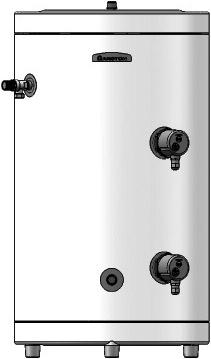
7 3. overall DiMensions ST ProTech1 Classico HE STD Classico HE STI Classico HE STD 5 Classico HE STI 5 table 1 Model Storage Units Pipe Size Coil Dimensions in mm Weight Surface When Full Capacity m 2 Kg Inlet Outlet A B C D E F G H I J Direct range Wallhung 141 ST 1 ProTech 1 l 3/ Floor Standing Classico STD 5 HE Classico STD 15 HE Classico STD 21 HE Classico STD 3 HE Classico STD 5 HE 5 l 15 l 2 l 3 l 5 l 3/4 Male 3/4 Male 3/4 Male 3/4" Male 1 Male indirect range Classico STI 5 HE Classico STI 15 HE Classico STI 21 HE Classico STI 3 HE Classico STI 5 HE 5 l 15 l 2 l 3 l 5 l 3/4 Male 3/4 Male 3/4 Male 3/4 Male 1" Male
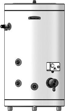
8 8AQUABRAVO ITD AQUABRAVO ITI AQUABRAVO ITSI table 1 Model Storage Units Pipe Size Coil Dimensions in mm Weight Surface When Full Capacity Kg Inlet Outlet A B C D E F G H I Kg Direct range AQUABRAVO ITD 13 AQUABRAVO ITD 15 AQUABRAVO ITD 215 AQUABRAVO ITD l 15 l 215 l 35 l Ø 22mm Ø 22mm Ø 22mm Ø 22mm indirect range AQUABRAVO ITI 8 AQUABRAVO ITI 13 AQUABRAVO ITI 15 AQUABRAVO ITI 215 AQUABRAVO ITI 255 AQUABRAVO ITI 35 twin coil range 8l 15l 15l 215l 255l 35l Ø 22mm Ø 22mm Ø 22mm Ø 22mm Ø 22mm Ø 22mm AQUABRAVO ITSI 215 (top/bottom) AQUABRAVO ITSI 255 (top/bottom) AQUABRAVO ITSI 35 (top/bottom) 215l 255l 35l Ø 22mm Ø 22mm Ø 22mm.5 / / /
9 3.8 connection of MAins water supply For floor standing models: On the front of the unit there is a label to identify the connection ports. Please check this before making any connection to the unit. For units up to 3 litres it is recommended that all mains cold water supply pipe work is a minimum of 22mm. For 5 litre models the supply should be 28mm. An isolating valve should be installed between the cold water supply and the cylinder for servicing. ALL PIPEWORK MUST BE FLUSHED TO AVOID DAMAGE TO THE CONTROL VALVES. Please refer to FiGs for a suggested installation layout. Draining taps must be located in acessible postions to permit the draining of the whole cylinder. The taps must be a minimal size of at least 15mm nominal size (preferably 22mm), and manufactured in accordance with BS 289:198. When installing the expansion vessel Ariston recommend it be connected directly to the combination valve (see Figs ). important note: When installing the expansion vessel, Do not install the expansion vessel vertically as air can become trapped in the expansion vessel resulting in noise. Do not use a flexible hose to connect the expansion vessel. This must be hard piped in order to avoid vibration. See below for acceptable installation practices. 9
10 st protech 1 std Direct FiG. 3.1 FiG. 3.2 sti indirect std 5 Direct FiG NOTE: FLOW AND RETURN PIPES MAY BE CONNECTED IN REVERSE TO THAT SHOWN IN THE DIAGRAMS FOR INDIRECT CYLINDERS. FiG. 3.4
11 itd Direct iti indirect FiG. FiG. 3. sti 5 indirect itsi twin coil FiG. 3. NOTE: FLOW AND RETURN PIPES MAY BE CONNECTED IN REVERSE TO THAT SHOWN IN THE DIAGRAMS FOR INDIRECT CYLINDERS. FiG
12 3.9 cold water combination valve The cold water combination valve may be fitted in close proximity to the cylinder, or alternatively, it may be separated to allow the pressure reducing valve where the mains supply enters the property allowing for balanced cold water throughout the whole property whilst the bar safety valve is fitted in close proximity to the cylinder. A balancing port is supplied on the 22mm and 28mm valves allowing balanced cold water supply to the rest of the building giving constant results for mixer and shower valves. If the facility is not needed a plug is supplied. Refer to FiG. 3.9 and FiG. 3.1 note! there should Be no other valves FitteD Between the cylinder AnD the expansion valve. EXPANSION RELIEF VALVE (SET AT BAR) SERVICEABLE 3/4 PRESSURE REDUCING CARTRIDGE AND LINE STRAINER (SET AT BAR) 15mm EXPANSION RELIEF OUTLET TO TUNDISH 22mm TO CYLINDER 22mm COLD MAINS IN 3/4 B.S.P. CONNECTION FOR EXPANSION VESSEL 22mm BALANCED COLD WATER TAKE OFF WITH NONRETURN VALVE FiG. 3.9 For ST 1, Aquabravo ITD, ITI, ITSI, Classico HE STD and STI models up to 3l
13 SERVICEABLE 1 PRESSURE REDUCING CARTRIDGE AND LINE STRAINER (SET AT BAR) EXPANSION RELIEF VALVE (SET AT BAR) 28mm COLD MAINS IN 28mm TO CYLINDER FiG BALANCED COLD WATER TAKE OFF WITH NONRETURN VALVE 3/4 B.S.P. CONNECTION FOR EXPANSION VESSEL For Classico HE STD and STI 5 models 3.1 connection to services It is recommended that a 22mm pipe run should supply the outlets throughout the building, especially to baths and showers. Short runs of 15mm pipe may be used to connect basins and sinks secondary return On selected floorstanding models a secondary return may be fitted (consult the drawings on pages 1 and 11 and the label on the face of the unit for presence/location). A nonreturn valve (not supplied) must be fitted to prevent back flow and a bronze pump will be needed in conjunction with a pipe thermostat and timer to circulate the hot water (both not supplied). Where a secondary return is not included on the cylinder, it is possible to utilise the mains inlet (see diagram below). note: an extra expansion vessel may be required where the additional volume of the secondary return exceeds the capacity of the expansion vessel supplied. 13
14 3. DiscHArGe pipework note! the safety relief valves Must not Be used For Any other purpose 1) Discharge pipes from the temperature & pressure relief and expansion relief valve may be joined together. 2) The tundish must be vertical and fitted within mm of the temperature & pressure relief valve and must be located with the cylinder but away from any electrical devices. The tundish must also be in a position visible to the occupants, and positioned away from any electrical devices. The discharge pipe from the tundish should of metal and terminate in a safe place where there is no risk to persons in the vicinity of the discharge. 3) The pipe diameter must be at least one pipe size larger than the nominal outlet size of the safety device unless it's total equivalent hydraulic resistance exceeds that of a straight pipe 9m long. i.e. Discharge pipes between 9m and 18m equivalent resistance length should be at least 2 sizes larger than the nominal outlet size of the safety device. Between 18m and 2m at least 3 larger, and so on. Bends must be taken into account in calculating the flow resistance. See FiG and table 2. 4) The discharge pipe must have a vertical section of pipe at least 3mm in length below the tundish, before any elbows or bends in the pipework. 5) The discharge pipe must be installed with a continuous fall and should be at least one pipe diameter clear of the wall where it terminates. ) The discharge should be visible at both the tundish and the final point of discharge, but where this is not possible or practically difficult; there should be clear visibility at one or other of these locations. Examples of acceptance are: i) Ideally below a fixed grating and above the water seal in a trapped gully. ii) Downward discharges at a low level; i.e. up to 1mm above external surfaces such as car parks, hard standings, grassed areas etc. These are acceptable providing that where children may play or otherwise come into contact with discharges, a wire cage or similar guard is positioned to prevent contact, whilst maintaining visibility. iii) Discharges at high level; Onto a roof capable of withstanding high temperature discharges of water 3m from any plastic guttering systems that would collect such a discharge (tundish visible). iv) Where a single pipe serves a number of discharges, such as in blocks of flats, i.e. into a metal hopper and metal down pipe with the end of the discharge pipe clearly visible (tundish visible or not). the number served should be limited to not more than systems so that any installation can be traced reasonably easily. The single common discharge pipe should be at least one pipe size large than the largest individual discharge pipe to be connected. If unvented hot water storage systems are installed where discharges from safety devices may not be apparent i.e. in dwellings occupied by the blind, infirm or disabled people, consideration should be given to the installation of an electronically operated device to warn when discharge takes place. Note: The discharge will consist of scalding water and steam. Asphalt, roofing felt and nonmetallic rainwater goods may be damaged by such discharges. 14
15 Temperature & pressure relief valve Metal discharge pipe (D1) from temperature & pressure relief valve. to tundish. mm Max. Tundish 3mm Min. Metal discharge pipe (D2) from tundish with continuous fall. See Table 2 and worked example. Discharge below fixed grating. (see page 1 for alternative points of discharge). Fixed grating FiG Trapped gulley table 2. Sizing of copper discharge pipe D2 for common temperature valve outlet sizes. Valve outlet size Minimum size of discharge pipe D1* Minimum size of discharge pipe D2* from tundish G 1/2 15mm 22mm 28mm 35mm G 3/4 22mm 28mm 35mm 42mm G 1 28mm 35mm 42mm 54mm Maximum resistance allowed, expressed as a length of pipe (i.e. no elbow or bends) Up to 9m Up to 18m Up to 2m Up to 9m Up to 18m Up to 2m Up to 9m Up to 18m Up to 2m Resistance created by each elbow or bend.8m 1.m 1.4m 1.m 1.4m 1.m 1.4m 1.m 2.3m 15
16 worked example The example below is for a G1 2 temperature & pressure relief valve with a discharge pipe (D2) having 4 no. elbows and length of m from the tundish to the point of discharge. From table 2; Maximum resistance allowed for a straight length of 22mm copper discharge pipe (D2) from G1 2 temperature & pressure valve is 9m. Subtract the resistance for 4 no. 22mm elbows at.8m each = 3.2m. Therefore the maximum permitted length equates to: 5.8m. As 5.8m is less than the actual length of m therefore calculate the next largest size. Maximum resistance allowed for a straight length of 28mm pipe (D2) from G1 2 temperature & pressure valve equates to: 18m. Subtract the resistance for 4 no. 28mm elbow at 1.m each = 4m. Therefore the maximum permitted length equates to: 14m As the actual length is m, a 28mm (D2) copper pipe will be satisfactory. warnings The outlet from the temperature & pressure relief valve must not be used for any other purpose. This also applies to the expansion relief valve. No other valve is to be fitted between the cold water combination valve and the cylinder. The temperature & pressure relief valve must not be removed in any circumstances. Any of the above will totally invalidate the guarantee. Discharge pipe D2 (FIG. 3.11) must be in metal and must not be discharged into a soil stack made of plastic or any other nonmetallic material incapable of withstanding discharge water above 95ºC. 1
17 3.13 electrical connection The electrical installation must be in accordance with the current I.E.E. wiring regulations. protech electronic Anticorrosion system (st 1 models only) important: The ProTech anticorrosion system MUST be permanently connected to a fused nonswitched 24V electricity supply. The ProTech system, an exclusive solution, is an electronic anticorrosion protection system which ensures maximum longevity of the appliance. The electronic circuit creates a difference in potential between the hot water tank and the titanium electrode, thereby guaranteeing optimum protection of the tank and preventing corrosion. Note: Do not use a water softner on products with the ProTech anticorrosion system. To ensure the proper operation of the protection system, it Must Be permanently connected to A FuseD nonswitched 24v, 3A electricity supply even in the event of shutdown of the system. To prevent risk to the appliance s lifespan when disconnecting the protection system for an extended period of time, it is necessary to drain the appliance beforehand. In addition to the 24V network, the electronic circuit is also connected to the tank, which is to be protected, and to the titanium protection electrode, information For the end user Proper operation of the protection system is shown by a continuous green L.E.D, indicating that the circuits terminals are being supplied with electricity. In the event of failure, a red LED indicates that there is a shortcircuit between the electrode and the cylinder tank, that one of the leads (tank or electrode) is disconnected or that there is no water in the cylinder. Your appliance is thus properly protected when the green L.E.D. is illuminated and the red LED is off. Should this not be the case or should the green and red LED light simultaneously, please contact your installer. Direct systems A mains supply of 24V, 3kW (13 amps) is required. Heat resistant cable, round 3 or 4 core 2.5mm 2 (to BS141 table 8) must be used to connect the electrical supply through the Economy time control switch using either system A or B as illustrated in Fig
18 system A system B FiG
19 3.14 electrical DiAGrAMs Should the Economy system not to be used, a separate 13 amp supply to each element will be required through a double pole fused isolating switch having a contact gap of at least 3mm on each pole.the immersion heater shall be installed with 85 C rubber insulated HOFRsheathed flexible cable complying with Table 8 of BS 141: Make the connection(s) to the immersion heater(s) as per FiG and FiG For High Capacity 5 litre models see FiG (page 2). Single Element THERMAL CUTOUT THERMOSTAT ELEMENT L1 N 3 kw 24V~ FiG L1 THERMAL CUTOUT THERMOSTAT DAY ELEMENT 3 kw 24V~ N L2 N THERMAL CUTOUT THERMOSTAT NIGHT ELEMENT 3 kw 24V~ ECONOMY FiG
20 FiG IMpORTANT: WHEN WIRING THE 5 LITRE CYLINDERS IMMERSION HEATER ENSURE THAT A SUITABLE HEAT RESISTANT CABLE RATED ABOVE THE PROTECTIVE DEVICE IS USED (I.E. MM FOR 32AMP). 2
21 Wiring diagram for two 2 Port Valves with Ariston GENUS HE, CLAS HE and CLAS boilers with 2 zone clip in fitted. NOTE: Enable Parameter 223 and change from to 1 GENUS Range program time zones 1 & 2 on digital display CLAS HE both zones timed from integral timer FiG. 3.1 note: with regards to the AQuABrAvo itsi cylinders, For More DetAileD wiring instructions please contact the technical DepArtMent on
22 Wiring diagram for two 2 Port Valves FiG. 3.1 note: with regards to the primo itsi cylinders, For More DetAileD wiring instructions please contact the technical DepArtMent on
23 Wiring diagram for a 3 Port Valve & 2 Port Valve FiG
24 4. COMMISSIONING The thermostat(s) on the immersion heater(s) should be adjusted to trip at 5 C. This is the ideal temperature to prolong element life in hard water areas. Scale on the sheath builds up more rapidly at temperatures above this causing the element to overheat and premature failure can occur. Higher temperatures without additional controls would result in scalding. In known hard water areas the use of a scale inhibitor is also recommended. In addition to the thermostat the thermal cutout will switch power off to the element should the thermostat malfunction, causing an excessive rise in water temperature. The thermal cutout can be reset manually after the fault has been corrected. indirect systems For models up to 3 litres a mains supply of 24V, 3kW (13 amps) will be required for the direct immersion heater. heat resistant cable, round 3 core 2.5mm 2 (to BS141) must be used. For High Capacity 5 litre models consult the wiring diagram on page 2 of this manual. For indirect controls a 24V, 3 amp supply is required. The cables must be clamped in position (as previously stated) and the control thermostat should be set at C for the reasons above. In addition to the thermostat there is a thermal cutout should the thermostat fail. Refer to FiG warning : the AppliAnce Must Be earthed. The earth continuity conductor of the electrical installation must be effectively connected to all exposed parts of other appliances and services in the room in which the water heater is to be installed and conform to the I.E.E. wiring regulations. note: Do not switch on the immersion heater or fire the boiler until the cylinder is full of water. Check for obvious signs of damage to the cylinder and controls, and also that the controls fitted correspond with the references quoted in these instructions. Ensure that the drain cock at the base of the appliance is closed before commencing. 1) ProTech Models Only. Ensure that the ProTech anticorrosion system is connected to the electrical supply; 2) Ensure that the line strainer (situated in the pressure reducing valve) is clear of installation debris and clean if necessary; 3) Check that the pressure in the expansion vessel is the same as the incoming water pressure; 4) Open all outlet taps; 5) Turn on mains water supply and allow the water heater to fill; ) Ensure that the hot water system is flushed in accordance with BS ; ) Close taps in turn after having purged the system of air; 24 8) Check for leaks around the controls and immersion heaters and again after the unit has heated up; 9) Check that no water is passing to waste through the relief valves;
25 1) Test the operation of the temperature & pressure relief and expansion valves by lifting/turning the manually operated test lever/cap and observing that water flows through freely and safely to waste; 11) Check that the discharge pipe is plumbed so that it falls continuously and that no taps, valves or other shut off devices are installed in the pipe; ) Check that all thermostats are set at approximately 5 C; 13) DIRECT UNITS. Switch on immersion heater(s) and allow unit to heat up. Check operation of thermostat(s); 14) INDIRECT UNITS. Fill the indirect (primary) circuit following the boiler instructions. Switch on the boiler, ensure that the programmer is in the domestic hot water position. Allow unit to heat up and check operation of indirect thermostat and motorised valve(s); 15) Check the temperature of the hot water at the nearest outlet and record in the Benchmark Commissioning Checklist; 1) Demonstrate operation to user, including operation of temperature & pressure relief valve and what to do if it operates; 1) Give this manual along with the completed Benchmark Commissioning Checklist to the user to retain for future reference and make the customer aware that periodic checks of the equipment are essential for safety. 25
26 5. MAINTENANCE To ensure efficient and safe operation, and to maintain the warranty, it is necessary to ensure the appliance is serviced annually by a competent person. After each service is finished, please ensure that the service record sheet (found towards the back of the manual) is completed by the engineer. Before servicing, preliminary electrical system checks must be carried out to ensure electrical safety (i.e. polarity, earth continuity, resistance to earth and short circuit). NOTE: While there is no direct inspection access point on the cylinder, it may be possible to use the immersion heater boss(es) for this purpose. 5.1 protech Anticorrosion system warning: SWITCH OFF THE POWER SUPPLY BEFORE WORKING ON THE APPLIANCE. troubleshooting: 1) The green L.E.D. is NOT on: Check to see that the circuits electric plug is connected (if not, connect); Check to see that the P.C.B, is supplied with electricity (if not, replace the supply cable); Check to see that 23 V electricity is supplied (if not, ensure that 23 V is supplied); If all these checks fail to locate the problem, replace the electronic circuit (installer). 2) The red L.E.D. is on: Check to see that the tank is filled with water (if not, fill it before carrying out the following checks); Check to see that the clipon circuit connector is in the proper position (if not, position correctly); Check to see that the electrodes connection lead is property connected (to check this, gently pull on it) (if not, replace the electrode); Check to see that the connection lead to the tank is properly connected to the tank (if not, connect properly);. Check to see that the two leads from the clipon circuit connector are not damaged, stripped, etc. (if so, replace the electrode); If all these checks fail to locate the problem, replace the electronic circuit. note: To replace the P.C.B, there is no need to drain the cylinder; 1) Disconnect the two supply cables from the P.C.B. to the supply terminal; 2) Disconnect the clipon circuit connector and polarising slot which connects the circuit to the tank and the electrode; 3) Disconnect the P.C.B. from its supporting plate (plastic clips in the 4 corners) and; 4) Replace the defective circuit with a new one, then reinstall in reverse order to the above. 5.2 thermal cutout(s) If the thermal cutout has operated the cause must be found before resetting (see section ). 5.3 immersion HeAter(s) Should the immersion heater(s) become scaled, we would recommend that the immersion heaters be replaced, a scale reducer be fitted on the cold water supply to the cylinder and that the thermostat is set below O C to prevent further scale formation. 5.4 unvented controls Check controls as per the following: 1) Line strainer with the water supply turned off remove screen from strainer and clean off any debris; 2) Expansion vessel with the water supply turned off and taps open, check 2
27 expansion vessel pressure and top up as necessary; 3) Temperature & pressure relief valve with the water supply turned on, check manually by lifting the test lever/turning the test knob (ensure valve closes after testing); 4) Expansion relief valve check manually by turning the test knob (ensure valve closes after testing); 5) Discharge pipes (D1) from both temperature & pressure relief and expansion relief valve for obstructions; ) Tundish & discharge pipe (D2) open either valve gradually to produce a full bore discharge into tundish and D2 without any back pressure; ) Pressure reducing valve check that the correct outlet pressure is being maintained by recording the pressure at an inline terminal fitting e.g. tap. 5.5 thermostats 5. MAintenAnce procedure IMPORTANT NOTE: TO AVOID POTENTIAL IMPLOSION OF THE CYLINDER WHILST DRAINING, ALL TAPS AND THE T&P VALVE MUST BE OPEN TO ALLOW AIR INTO THE CYLINDER DURING THE DRAINING PROCESS. Ensure that all thermostats are adjusted for the correct temperature setting, this should be between and 5 C. To ensure efficient and safe operation, and to maintain the warranty, it is necesary to ensure the appliance is serviced annually by a competent person. After each service is finished, please ensure that the service record sheet (found towards the back of the manual) is completed by the engineer. After servicing, preliminary electrical system checks must be carried out to ensure electrical safety (i.e. polarity, earth continuity, resistance to earth and short circuit). To drain the cylinder it is necessary to proceed as follows: 1) Close the mains supply service valve; 2) Open hot water taps; 3) Attach a hose and open the drain cock and allow the cylinder to empty, taking care of hot water contained in the cylinder. (Pumping the water out will completely drain the cylinder) Magnesium Anodes (std and sti models only) No longer than every months, the installer should check the magnesium anticorrosion anodes (consult the label on the face of the unit for the correct location). Assessment of the condition of the bottom anode (where fitted) can be made by judging the condition of the top anode. Removal of anodes; 1) Close the mains supply service valve; 2) Open hot water taps; 3) Attach a hose and open the drain cock and allow the cylinder to empty; 4) The anodes are removed by unscrewing; EXAMINE THE ANODES AND IF THE DIAMETER IS LESS THAN 1mm replace both anodes. The use of an approved P.T.F.E. sealing tape is required to ensure watertight connection for anodes. thermal cutout(s) If the thermal cutout has operated the cause must be found before resetting. immersion Heater(s) Should the immersion heater be scaled, we would recommend it be replaced. 2
28 unvented controls(s) Check controls as per the following: 1) Line strainer with the water supply turned off remove screen from strainer and clean of any detritus; 2) Expansion vessel with the water supply turned off and taps open, check expansion vessel pressure and top up as necessary; 3) Temperature & pressure relief valve with the water supply turned on, check manually by lifting the test lever/turning the test knob (ensure valve closes after testing); 4) Expansion relief valve check manually by turning the test knob (ensure valve closes after testing); 5) Discharge pipes (D1) from both temperature & pressure relief and expansion relief valve for obstructions; ) Tundish & discharge pipe (D2) open either valve gradually to produce a full bore discharge into tundish and D2 without any back pressure; ) Pressure reducing valve check that the correct outlet pressure is being maintained by recording the pressure at an inline terminal fitting i.e. tap. thermostats Ensure that all thermostats adjusted for the correct temperature setting, this should be between and 5 C. After servicing, complete Benchmark Service Record located on page 35 of this manual. note! where there is A possibility of scale ForMinG, it is recommended the thermostat Be set to Below o c AnD A scale reducer Be FitteD on the incoming MAins supply 28
29 . FAuLT FINdING FAult possible causes remedy 1) Mains cold water Check and open Isolating supply shut off and/or stop valve. Check water, Local Water Authority no Hot water 2) Line strainer Turn off mains water supply, Flow blocked remove line strainer and clean 3) Cold Water Check direction of flow Combination valve arrows on valve, refit in fitted incorrectly correct position if necessary 1) Low mains water Check pressure, consult pressure Local Water Authority if necessary reduced Flow 2) Line strainer Turn off mains water supply, rate partially blocked remove line strainer and clean 3) Size of service Increase to size stated on pipe too small page 9 1) Direct immersion Check immersion heater, heater is not switch on if necessary switched on 2) Direct thermal Test thermostat operation cutout has and wiring, if faulty, operated correct/replace. Reset cutout water FroM 3) Boiler programmer Check switch on domestic Hot taps set to central hot water if necessary is cold heating only (Indirect models) 4) Boiler is not Check boiler operation, if functioning fault suspected consult (Indirect models) manufacturer's instructions 5) Indirect thermal Test thermostat operation cutout has and wiring, if faulty, operated correct/replace. Reset cutout ) Motorised valve Check wiring and operation of jammed or not motorised valve correct/ wired correctly replace as necessary (Indirect models) DiscHArGe FroM 1) Pressure above Shut down boiler or immersion pressure/ bar, failure of heater. Check pressure temperature pressure reducing reducing valve and thermal relief valve valve. Temperature controls. Replace if above 9ºC failure necessary of thermal control DiscHArGe FroM 1) Continually. Check pressure from valve. expansion Pressure reducing Replace if over bar valve valve faulty 2) When heater is heating. Check charge of vessel. Re Faulty expansion charge vessel to bar or match vessel or lost charge incoming mains pressure replace if necessary 3) Back feed of high mains Service / replace mixer pressure via mixer. water HAMMer 1) Expansion Vessel fitted Ensure vessel is fitted horizontally or vertically. connection at top. 2) Pipework not secure Clip pipework 3) Jumpers on taps loose Replace tap jumpers 4) Flexible hose connecting Remove flexible hose and hard pipe. expansion vessel 29
30 . TEChNICAL data ST Protech 1 Classico STD 5 HE Classico STD 15 HE Classico STD 21 HE Classico STD 3 HE Classico STD 5 HE Classico STI 5 HE Classico STI 15 HE Classico STI 21 HE Classico STI 3 HE Classico STI 5 HE Nominal Capacity ** l Maximum Water Supply Pressure* bar Maximum Design Pressure bar Operating Pressure bar Expansion Vessel Charge Pressure bar Expansion Relief Valve Setting bar Pressure & Temperature Relief Valve Setting bar/ C Pressure Reducing Valve Set Pressure bar Electrical Supply V Immersion Heater Rating kw Immersion Heater Type Direct Reheat Time (Single element) (1%) h:min Direct Reheat Time (Single element) (%) h:min Maximum Primary Pressure bar Maximum Operating Temperature (heating fluid) ºC Pressure Drop Through Primary Coil mbar Primary Flow Rate m 3 /h Heat Exchanger Performance (Flow rate.9m 3 /h) kw Coil Surface Area m 2 min min Reheat Time ** Indirect Reheat Time (%) Heat Loss (kwh in 24h) EN 39 Nett Weight Ozone Depletion Potential (ODP) Global Warming Potential (GWP) Kg 1 / :5 1: / :2 148 / / / /9 24/4 (2) 3: 4: :15 4:2 2:5 1:4 2:1 2:55 4: / tba / tba / tba / tba /9 24/4 (2) 85 tba Note: The above cylinders were tested in accordance with EN89:2 * To pressure reducing valve ** Tested in accordance with EN89:2 Single Phase (2) Single Phase/Three phase The power consumption data in the table and the other information given in the Product Data Sheet (Annex A attached to the product) are defined in relation to EU Directives 8/213 and 814/213. Model CLASSICO STD CLASSICO STI Make of Pressure Reducing Valve Make of Make of Safety Valve T&P Valve Intatec Bar (22mm) Intatec Bar (22mm) Intatec Bar (15mm) Intatec Bar (22mm) Intatec Bar (22mm) Intatec Bar (15mm) 3
31 AQUABRAVO ITD 13 AQUABRAVO ITD 15 AQUABRAVO ITD 215 AQUABRAVO ITD 35 AQUABRAVO ITI 8 AQUABRAVO ITI 13 AQUABRAVO ITI 15 AQUABRAVO ITI 215 AQUABRAVO ITI 255 AQUABRAVO ITI 35 AQUABRAVO ITSI 215 AQUABRAVO ITSI 255 AQUABRAVO ITSI 35 Nominal Capacity ** l Maximum Water Supply Pressure* bar Maximum Design Pressure bar Operating Pressure bar Expansion Vessel Charge Pressure bar Expansion Relief Valve Setting bar Pressure & Temperature Relief Valve Setting bar/ C Pressure Reducing Valve Set Pressure bar Electrical Supply V Immersion Heater Rating kw Immersion Heater Type Direct Reheat Time (Single element) (1%) h:min Direct Reheat Time (Single element) (%) h:min Maximum Primary Pressure bar Maximum Operating Temperature (heating fluid) ºC Pressure Drop Through Primary Coil mbar Primary Flow Rate m 3 /h Heat Exchanger Performance (Flow rate.9m 3 /h) kw Coil Surface Area m 2 Reheat Time ** Indirect Reheat Time (%) min min Heat Loss (kwh in 24h) EN 39 Nett Weight Kg Ozone Depletion Potential (ODP) Global Warming Potential (GWP) / :4 2: / :19 2: / :51 3: / :19 4:5 / :33 1: / :4 2: / :19 2: / :51 3: / :5 3: / :19 4: / tba tba 2./2. 1.1/ / tba tba 2./2. 1.1/ / tba tba 2./2. 1.1/ Note: The above cylinders were tested in accordance with EN89 * To pressure reducing valve ** Tested in accordance with EN89:2 Single Phase The power consumption data in the table and the other information given in the Product Data Sheet (Annex A attached to the product) are defined in relation to EU Directives 8/213 and 814/213. Model AQUAVBRAVO ITI 13 Make of Pressure Reducing Valve Make of Safety Valve Make of T&P Valve Intatec Bar (22mm) Intatec Bar (22mm) Intatec Bar (15mm) AQUABRAVO ITD 13 Intatec Bar (22mm) Intatec Bar (22mm) Intatec Bar (15mm) AQUABRAVO ITSI 21 3 Intatec Bar (22mm) Intatec Bar (22mm) Intatec Bar (15mm) 31
32 8. BENChMARK COMMISSIONING ChECKLIST MAINS PRESSURE HOT WATER STORAGE SYSTEM COMMISSIONING CHECKLIST This Commissioning Checklist is to be completed in full by the competent person who commissioned the storage system as a means of demonstrating compliance with the appropriate Building Regulations and then handed to the customer to keep for future reference. Failure to install and commission this equipment to the manufacturer s instructions may invalidate the warranty but does not affect statutory rights. Customer name: Telephone number: Address: Cylinder Make and Model Cylinder Serial Number Commissioned by (PRINT NAME): Company name: Registered Operative ID Number Telephone number: Company address: Commissioning date: To be completed by the customer on receipt of a Building Regulations Compliance Certificate*: Building Regulations Notification Number (if applicable) ALL SYSTEMS PRIMARY SETTINGS (indirect heating only) Is the primary circuit a sealed or open vented system? Sealed Open What is the maximum primary flow temperature? C ALL SYSTEMS What is the incoming static cold water pressure at the inlet to the system? Has a strainer been cleaned of installation debris (if fitted)? Is the installation in a hard water area (above 2ppm)? If yes, has a water scale reducer been fitted? What type of scale reducer has been fitted? What is the hot water thermostat set temperature? What is the maximum hot water flow rate at set thermostat temperature (measured at high flow outlet)? Time and temperature controls have been fitted in compliance with Part L of the Building Regulations? Type of control system (if applicable) Is the cylinder solar (or other renewable) compatible? What is the hot water temperature at the nearest outlet? All appropriate pipes have been insulated up to 1 metre or the point where they become concealed bar Yes No Yes No Yes No C I/min Yes Y Plan S Plan Other Yes No C Yes UNVENTED SYSTEMS ONLY Where is the pressure reducing valve situated (if fitted)? What is the pressure reducing valve setting? bar Has a combined temperature and pressure relief valve and expansion valve been fitted and discharge tested? The tundish and discharge pipework have been connected and terminated to Part G of the Building Regulations Yes No Yes Are all energy sources fitted with a cut out device? Yes No Has the expansion vessel or internal air space been checked? Yes No THERMAL STORES ONLY What store temperature is achievable? What is the maximum hot water temperature? C C ALL INSTALLATIONS The hot water system complies with the appropriate Building Regulations The system has been installed and commissioned in accordance with the manufacturer s instructions The system controls have been demonstrated to and understood by the customer The manufacturer s literature, including Benchmark Checklist and Service Record, has been explained and left with the customer Yes Yes Yes Yes Commissioning Engineer s Signature Customer s Signature (To confirm satisfactory demonstration and receipt of manufacturer s literature) * All installations in England and Wales must be notified to Local Authority Building Control (LABC) either directly or through a Competent Persons Scheme. A Building Regulations Compliance Certificate will then be issued to the customer. 32 Heating and Hotwater Industry Council (HHIC)
33 9. BENChMARK SERVICE RECORd It is recommended that your hot water system is serviced regularly and that the appropriate Service Record is completed. Service Provider Before completing the appropriate Service Record below, please ensure you have carried out the service as described in the manufacturer s instructions. SERVICE 1 Date: SERVICE 2 Date: Engineer name: Engineer name: Company name: Company name: Telephone No: Telephone No: Comments: Comments: Signature Signature SERVICE 3 Date: SERVICE 4 Date: Engineer name: Engineer name: Company name: Company name: Telephone No: Telephone No: Comments: Comments: Signature Signature SERVICE 5 Date: SERVICE Date: Engineer name: Engineer name: Company name: Company name: Telephone No: Telephone No: Comments: Comments: Signature Signature SERVICE Date: SERVICE 8 Date: Engineer name: Engineer name: Company name: Company name: Telephone No: Telephone No: Comments: Comments: Signature Signature SERVICE 9 Date: SERVICE 1 Date: Engineer name: Engineer name: Company name: Company name: Telephone No: Telephone No: Comments: Comments: Signature Signature 33
Unvented Calorifier Range. Operating and Maintenance Manual. For Models & 500
 Unvented Calorifier Range. Operating and Maintenance Manual. For Models 125 300 & 500 Telephone 08456 448802 Fax 08456 448803 Emial info@mhgheating.co.uk Web www.mhgheating.co.uk TABLE OF CONTENTS. Section
Unvented Hot Water Storage Cylinders
 Unvented Hot Water Storage Cylinders Instructions for Installation, Servicing and Use LEAVE THESE INSTRUCTIONS WITH THE ENDUSER Country of destination: GB/IE TABLE OF CONTENTS 1. GENERAL INFORMATION Page
Instructions for Installation, Servicing and Use
 Instructions for Installation, Servicing and Use Unvented Hot Water Storage Cylinders Country of destination: GB/IE TABLE OF CONTENTS 1. THE BENCHMARK SCHEME Page 2 2. GENERAL INFORMATION Page 3 2.1 Guarantee
Unvented Hot Water Storage Cylinders Installation and Maintenance Instruction Manual
 Unvented Hot Water Storage Cylinders Installation and Maintenance Instruction Manual Including User Instructions Customer Care and Guarantee Chaffoteaux & Maury, as a leading manufacturer of domestic and
Unvented water heater
 Unvented water heater Description of water heater 1)Hot water outlet 2)Temperature and pressure relief valve (30 litre only) 3)Cold water inlet 4)Control cover 5)Regulation knob 6)Heating neon Over-sink
MW & EW 10 & 15 Litre Unvented Water Heaters HANDBOOK. IMPORTANT: This booklet should be given to the customer after installation and demonstration.
 MW & EW 10 & 15 Litre Unvented Water Heaters HANDBOOK IMPORTANT: This booklet should be given to the customer after installation and demonstration. Description of water heater 1) Hot water outlet 2) Temperature
INSTALLATION MANUAL. RD SERIES Digital Electric Water Heater Wall-hung Unvented
 INSTALLATION MANUAL RD SERIES Digital Electric Water Heater Wall-hung Unvented WELCOME Dear Customer, Thank you for choosing the RD Series electric water heater, with an exclusive electronic temperature
Instructions for Installation, Servicing and Use LEAVE THESE INSTRUCTIONS WITH THE END-USER. Unvented Hot Water Storage Cylinders
 Instructions for Installation, Servicing and Use LEAVE THESE INSTRUCTIONS WITH THE ENDUSER Unvented Hot Water Storage Cylinders TABLE OF CONTENTS 1. GENERAL INFORMATION 1.1 DELIVERY 2. INSTALLATION 2.1
PLEASE LEAVE THIS MANUAL WITH THE OSO UNIT AFTER INSTALLATION INSTALLATION MANUAL
 PLEASE LEAVE THIS MANUAL WITH THE OSO UNIT AFTER INSTALLATION SOLARCYL IM/SC INSTALLATION MANUAL This manual gives detailed advice for installation and should be read carefully prior to fitting any unvented
INSTALLATION MANUAL. Ecoline Geo RI HP PLEASE LEAVE THIS MANUAL WITH THE OSO UNIT AFTER INSTALLATION
 PLEASE LEAVE THIS MANUAL WITH THE OSO UNIT AFTER INSTALLATION Ecoline Geo RI HP INSTALLATION MANUAL The Ecoline GEO is an indirect unvented cylinder designed and approved for use with a heat pump. The
CROWN WATER HEATERS CPU10 - CPU15 CPOS10 - CPOS15
 CROWN WATER HEATERS CPU10 - CPU15 CPOS10 - CPOS15 COMPACT PLUS 10 and 15 Litre Unvented Under and Over Sink Water Heater INSTALLATION AND USER GUIDE 1 DIMENSIONS 10L - 250mm 15L - 310mm 100mm 80mm 410mm
1845 Tech Manual.qxd 23/11/05 1:20 pm Page 2 EXCELSIOR UNVENTED WATER HEATERS INSTALLATION MANUAL. Design for living
 1845 Tech Manual.qxd 23/11/05 1:20 pm Page 2 EXCELSIOR UNVENTED WATER HEATERS INSTALLATION MANUAL Design for living 1845 Tech Manual.qxd 23/11/05 1:21 pm Page 3 TECHNICAL DATA & INSTALLATION INSTRUCTIONS
ZIP Varipoint III. Installation, Maintenance and User Instructions. Models VP303, VP503 VP803, VP953 direct unvented water heaters. Issued August 2008
 Varipoint cover qxd:varipoint cover qxd 22/8/08 11:14 Page 1 Installation, Maintenance and User Instructions ZIP Varipoint III Models VP303, VP503 VP803, VP953 direct unvented water heaters Issued August
PLEASE LEAVE THIS MANUAL WITH THE OSO UNIT AFTER INSTALLATION INSTALLATION MANUAL
 PLEASE LEAVE THIS MANUAL WITH THE OSO UNIT AFTER INSTALLATION 0 RD 0 RI 0000-06 IM/ IM/a INSTALLATION MANUAL This manual gives detailed advice for installation and should be read carefully prior to fitting
Unvented water heater
 Unvented water heater Description of water heater 1)Hot water outlet 2)Temperature and pressure relief valve (30 litre only) 3)Cold water inlet 4)Control cover 5)Regulation knob 6)Heating neon Over-sink
Installation and User Instructions Aquaheat Unvented Water Heaters Models: AH30H
 Installation and User Instructions Aquaheat Unvented Water Heaters Models: AH30H Please read and understand these instructions before starting work. Please leave this leaflet with the user following installation
Furrows Business Park, Haybridge Road Wellington, Telford, Shropshire TF1 2FE
 WATERHEATER MANUFACTURERS ASSOCIATION Tel 01952 257963 Fax 01952 253452 Furrows Business Park, Haybridge Road Wellington, Telford, Shropshire TF1 2FE www.telford-group.com STAINLESS PRODUCTS Tornado &
TABLE OF CONTENTS TECHNICAL DOCUMENTATION 03. Technical Data Electrical Details Connection Details Dimensions Standing Losses
 INSPIRED H I G H H O T EF F ICIENCY E F F I C I E N C Y W A T E R S Y S T E M S E XT REME HIGH EFFICIENCY HO T W AT ER SY ST EMS w i th I N JECT I O N DYN A M I C S T ECHN I CAL DO CUME N TA T I O N I
Unvented Hot Water Storage Cylinders
 ti) ARISTON Instructions for Installation, Servicing and Use Unvented Hot Water Storage Cylinders Country of destination: GB/IE ce benchmark i kiwa kiwa TABLE OF CONTENTS 1. THE BENCHMARK SCHEME Page 2
ADVANCE STAINLESS STEEL UNVENTED HOT WATER SYSTEMS
 ISSUE 2 DECEMBER 2013 INSTALLATION AND USER GUIDE ADVANCE STAINLESS STEEL UNVENTED HOT WATER SYSTEMS FOR GAS, OIL, ELECTRIC SOLAR AND HEAT PUMP SYSTEMS ADVANCE APPLIANCES LTD PLEASE RETAIN AND ENSURE SERVICE
SEALED THERMAL STORE
 ISSUE 3 0717 INSTALLATION AND USER GUIDE ENERGYMANAGER SEALED THERMAL STORE ADVANCE APPLIANCES LTD PLEASE RETAIN AND ENSURE SERVICE RECORDS ARE KEPT UP TO DATE. SCHEMATIC DIAGRAM OF ENERYMANAGER THERMAL
Extreme Domestic Hot Water Loading System TECHNICAL DOCUMENTATION. Issue 11/09
 I N S P I R E D E F F I C I E N C Y Extreme Domestic Hot Water Loading System TECHNICAL DOCUMENTATION Issue 11/09 Technical data Description Extreme 200 Extreme 300 Extreme 500 Weight (empty) kg 63 77
unvented indirect & sealed heating systems unvented direct system & electric space heating Hot and cold water supply to all outlets at mains pressure
 Heating Hot water Renewables UNVENTED CYLINDERS 80-500 LITRES Maximum hot water, minimum fuss Being able to turn on any tap in the home and get hot and cold water at mains pressure is something that we
KYROS INSTALLATION MANUAL KYROS. Digital Electric Water Heater Wall-hung Unvented
 KYROS INSTALLATION MANUAL KYROS Digital Electric Water Heater Wall-hung Unvented 02 KYROS WELCOME Dear Customer, Thank you for choosing the KYROS electric water heater, with an exclusive electronic temperature
Quantum. Installation, User and Service Manual. Hot Spring
 Hot Spring Domestic Hot Water Cylinder Storage Capacities 90, 125, 150, 170, 200, 250 and 300 Litres 1 Important - This Manual should be left with the householder after installation Index Section Page
Unvented Direct & Indirect Hot Water Cylinders (400L L)
") Unvented Direct & Indirect Hot Water Cylinders (400L - 2500L) Important Please read & understand all these instructions before commencing installation. Please leave this manual with the customer for future
Unvented Direct & Indirect Hot Water Cylinders (400L - 2500L) Important Please read & understand all these instructions before commencing installation. Please leave this manual with the customer for future
Installation Manual EXCELSIOR Unvented Water Heater
 March 2014 Installation Manual EXCELSIOR Unvented Water Heater EXCELSIOR Water heating systems Contents Section: Title: Page: 1 Introduction 3 1.1 Specifier s Guide 3 1.2 Standard Equipment 4 2 Dimensions
Technical and Installation manual All Models
 WATER CONTROL setting the standards Technical and Installation manual All Models CONTENTS CONTENTS Section 1 Introduction 1-1 Introduction ---------------------------------------------- 2 1-2 System Layout
AquaFlo II. Issue 3 December Please read these instructions carefully before commencing installation of the AquaFlo unvented water heater
 Installation, Maintenance and User Instructions AquaFlo II Issue 3 December 2011 Please read these instructions carefully before commencing installation of the AquaFlo unvented water heater Please leave
WATER HEATERS INSTALLATION MANUAL
 MHG Heating Ltd UNVENTED WATER HEATERS INSTALLATION MANUAL INCLUDING SOLAR VESSELS Techni cal data & installation instructions for MHG direct & indirect unvented water heaters including solar models. Your
Unvented Direct & Indirect Hot Water Cylinders (400L L)
") Unvented Direct & Indirect Hot Water Cylinders (400L - 2500L) Important Please read & understand all these instructions before commencing installation. Please leave this manual with the customer for future
Unvented Direct & Indirect Hot Water Cylinders (400L - 2500L) Important Please read & understand all these instructions before commencing installation. Please leave this manual with the customer for future
Alpha CombiMax 350 and 600
 Installation and Servicing Instructions Alpha CombiMax 350 and 600 Unvented Hot Water Store for use with the Alpha 240/280 Range of Gas Fired Combination Boilers For Technical help or for Service call...
INSTALLATION MANUAL. Ecoline Geo RI HP PLEASE LEAVE THIS MANUAL WITH THE OSO UNIT AFTER INSTALLATION
 PLEASE LEAVE THIS MANUAL WITH THE OSO UNIT AFTER INSTALLATION 142039-02 GEO 9-2015 Ecoline Geo RI HP INSTALLATION MANUAL The Ecoline GEO is an indirect unvented cylinder designed and approved for use with
Instructions for Use Installation and Servicing
 0020004886A 18.01.05 Instructions for Use Installation and Servicing To be left with the user 12563 115-150-175-200-250-300 Unvented hot water storage cylinders Glow-worm, Nottingham Road, Belper, Derbyshire.
ENERSTORE. Vented Hot Water Storage System INSTRUCTIONS PLEASE LEAVE WITH HOUSEHOLDER
 ENERSTORE Vented Hot Water Storage System INSTRUCTIONS PLEASE LEAVE WITH HOUSEHOLDER Newark Copper Cylinder Co Ltd Brunel Drive Newark Notts. NG24 2EG Tel: 01636 678437 Fax: 01636 678964 Internet: www.newarkcoppercylinder.co.uk
Unvented Electric Water Heater 10/15 litre Undersink
 Unvented Electric Water Heater 10/15 litre Undersink Fitting Instructions and User Guide 1 CONTENTS SECTION PAGE 1.0 INTRODUCTION 2 2.0 TECHNICAL SPECIFICATION 3 3.0 INSTALLATION 4 4.0 COMMISSIONING 9
POWERFLOW Series. Unvented Electric Storage Water Heaters. Installation & Operating Instructions Manual
 POWERFLOW Series Unvented Electric Storage Water Heaters Installation & Operating Instructions Manual These Instructions must be left with the user after installation. Version 3.0 June 2009 Hyco POWERFLOW
Schuco SS-TC/SC Cylinders
 Cylinders Installation, User and Service Domestic Hot Water Cylinder Storage Capacities 90, 125, 150, 170, 200, 250 & 300, Litres Important -This should be left with the Cylinder after Installation Schueco
Instructions & Maintenance
 Instructions & Maintenance Issue 1 INTRODUCTION The corrosion resistant UVGold Unvented cylinder is made from Duplex Stainless Steel. It is highly insulated with environmentally friendly foam enclosed
MEGAFLO Eco Plus Solar Unvented Hot Water Cylinders 400L -570L
 MEGAFLO Eco Plus Solar Unvented Hot Water Cylinders 400L -570L Important Please read & understand all these instructions before commencing installation. Please leave this manual with the customer for future
PLEASE LEAVE THIS MANUAL WITH THE OSO UNIT AFTER INSTALLATION INSTALLATION MANUAL
 PLEASE LEAVE THIS MANUAL WITH THE OSO UNIT AFTER INSTALLATION SLIMLINE INSTALLATION MANUAL This cylinder is manufactured and approved in accordance with EN 897:006. This manual gives detailed advice for
Introduction. There is no obligation to follow the methods or comply with the standards set out in this Technical Booklet.
 Introduction This Technical Booklet has been prepared by the Department of the Environment for Northern Ireland and provides for certain methods and standards of building which, if followed, will satisfy
ADVANCE ELECTRIC THERMAL STORE
 ISSUE 13 1118 INSTALLATION AND USER GUIDE ADVANCE ELECTRIC THERMAL STORE ADVANCE APPLIANCES LTD HOUSEHOLDER PLEASE RETAIN AND ENSURE SERVICE RECORDS ARE KEPT UP TO DATE. 2 INTRODUCTION Advance thermal
ADVANCE ECB ELECTRIC COMBINATION BOILER
 ISSUE ISSUE 45 0115 0317 INSTALLATION AND USER GUIDE ADVANCE ECB ELECTRIC COMBINATION BOILER ADVANCE APPLIANCES LTD HOUSEHOLDER - PLEASE RETAIN AND ENSURE SERVICE RECORDS ARE KEPT UP TO DATE 1 SCHEMATIC
MULTIPOINT SS H 50/80 & 100
 MULTIPOINT SS H 50/80 & 100 Fitting Instructions and User Guide CONTENTS SECTION PAGE 1.0 INTRODUCTION 3 2.0 TECHNICAL SPECIFICATION 4 3.0 INSTALLATION 7 4.0 COMMISSIONING 14 5.0 EXPLANATION TO USER 15
EPU - WM30 EPU - WM 50 EPU - WM100
 INSTALLATION INSTRUCTIONS WALL HUNG WATER HEATERS EPU - WM30 EPU - WM 50 EPU - WM100 MARCH 2018 PART NO. 025217 01 EVERFLO IMPORTANT NOTE TO THE INSTALLER Read these instructions before commencing installation.
PremierPlus Unvented Hot Water Cylinder Installation and User Manual
 PremierPlus Unvented Hot Water Cylinder Installation and User Manual 7032982_issue 07.indd 1 05/09/2017 12:17:57 Contents 1. Introduction... 3 1.1 General... 3 1.2 Symbols used... 3 1.3 Abbreviations...
UNVENTED MAINS PRESSURE SOLAR WATER HEATERS 210, 250 AND 300 LITRE CAPACITY INDIRECT MODELS INSTALLATION AND SERVICING INSTRUCTIONS
 UNVENTED MAINS PRESSURE SOLAR WATER HEATERS 210, 250 AND 300 LITRE CAPACITY INDIRECT MODELS INSTALLATION AND SERVICING INSTRUCTIONS PACK CONTENTS The MAIN SOLAR unvented solar cylinder water heater incorporating
smart line E SLE
 smart line E SLE 130 300 INDEX INTRODUCTION 1 Intended users of these instructions 1 Warnings 1 1. Operation 2 2. Construction 3 3. Installation Domestic 4 Wiring the thermostats 5 Primary 5 Immersion
Megaflo Eco Plus Unvented Indirect Hot Water Cylinders 800L L
 Megaflo Eco Plus Unvented Indirect Hot Water Cylinders 800L - 1000L Important Please read & understand all these instructions before commencing installation. Please leave this manual with the customer
UNVENTED CYLINDER RANGE
 UNVENTED CYLINDER RANGE UNVENTED WATER STORAGE CYLINDER No longer than every 12 months, the magnesium anticorrosion anodes should be checked by your service engineer/installer. Installation and Users Guide
ZIP AquaFlo II. Models: Direct, Indirect and Solar Compatible. Unvented cylinder water heaters
 Installation & User Instructions ZIP AquaFlo II Unvented cylinder water heaters Models: Direct, Indirect and Solar Compatible. AquaFlo Installation, Maintenance and User Instructions Page 1 of 28 v 2.04
Installation and User Instructions HS10U, HS15U.
 Installation and User Instructions HS10U, HS15U. MULTIPOINT Please read and understand these instructions before starting work. Please leave this leaflet with the user following installation PACK CONTENTS
Tristor MF. Installation Guide
 Tristor MF Installation Guide Tel 1952 257963 Fax 1952 253452 Furrows Business Park, Haybridge Road Wellington, Telford, Shropshire TF1 2FE www.telford-group.com NOV 24 Parts Installer Replaced Registration
PLEASE LEAVE THIS MANUAL WITH THE OSO UNIT AFTER INSTALLATION INSTALLATION MANUAL
 PLEASE LEAVE THIS MANUAL WITH THE OSO UNIT AFTER INSTALLATION 09-0 05-05 INSTALLATION MANUAL This cylinder is manufactured and approved in accordance with EN 897:006. This manual gives detailed advice
Commissioning Pack. Heating and Hot Water Heat Pumps. IMPORTANT DOCUMENTS To Be Kept At All Times. With Equipment. Accredited Ecodan Installer:
 Accredited Ecodan Installer: Telephone: Email: Address: Commissioning Pack Heating and Hot Water Heat Pumps IMPORTANT DOCUMENTS To Be Kept At All Times With Equipment IMPORTANT This Sheet Must Be Kept
For latest prices and delivery to your door visit MyTub Ltd
 Heating Hot water Renewables UNVENTED CYLINDERS 100 TO 500 LITRES Maximum hot water, minimum fuss Being able to turn on any tap in the home and get hot and cold water at mains pressure is something that
INTRODUCTION STORAGE PRIOR TO INSTALLATION. Expansion Vessel Hose. Part No High Flow Rate Inlet Control Set. Part No.
 INTRODUCTION The Worcester Greenskies cylinder is a Stainless Steel Unvented Twin Coil Storage vessel specifically designed to be installed in conjunction with the Worcester Greenskies solar package. Should
Hotflo. Unvented point of use hot water
 Unvented point of use hot water We developed the range for people who need a hot water supply for two to three basins or sinks. Flexible siting is a key design feature that we insisted upon because it
Flomaster. Unvented Hot Water Cylinders INSTALLATION INSTRUCTIONS FOR COPPERFORM FLOMASTER UNVENTED CYLINDERS: DIRECT, INDIRECT AND SOLAR MODELS.
 Flomaster Unvented Hot Water Cylinders IMPORTANT NOTE TO THE INSTALLER Read these instructions before commencing installation. Unvented cylinders are a controlled service as defined in the latest edition
Installation and User Instructions Aquaheat Unvented Water Heaters Models: SS V 50/80 & 100
 Installation and User Instructions Aquaheat Unvented Water Heaters Models: SS V 50/80 & 100 Please read and understand these instructions before starting work. Please leave this leaflet with the user following
aurostor Installation and maintenance instructions Installation and maintenance instructions For the competent person GB, IE VIH S GB...
 Installation and maintenance instructions For the competent person Installation and maintenance instructions aurostor VIH S GB.../3 GB, IE Publisher/manufacturer Vaillant GmbH Berghauser Str. 40 D-4859
R e n e w a b l e s. Tribune HE Unvented Hot Water Cylinders Installation and Maintenance Instructions. Issue 14 May 2011 Part No.
 R e n e w a b l e s Tribune HE Unvented Hot Water Cylinders Installation and Maintenance Instructions Issue 14 May 2011 Part No. BOOKTRIB IMPORTANT NOTE TO THE INSTALLER Read these instructions before
Unvented water heating
 Unvented water heating Multipoint 75 / 100 95 900 871 Issue 1 Introduction 03 Unvented water heating The demand for unvented systems continues to increase as their benefits are recognised by specifiers,
Installation and Servicing Instructions. Alpha CD50
 Installation and Servicing Instructions Alpha CD50 Wall Mounted, Fan Assisted, Room Sealed, Gas Fired, High Efficiency, Condensing Combination Boiler with Unvented Hot Water Storage For Technical help
MULTIPOINT 30 & 50 Litre
 MULTIPOINT 30 & 50 Litre Installation and User Instructions 1 2 CONTENTS SECTION PAGE 1.0 INTRODUCTION 2 2.0 TECHNICAL SPECIFICATION 4 3.0 INSTALLATION 5 4.0 COMMISSIONING 12 5.0 USER DEMONSTRATION 13
Unvented Direct & Indirect Hot Water Cylinders
 Unvented Direct & Indirect Hot Water Cylinders Megaflo Product Guide Contents Product Specification...Page 3 Installation and Commissioning Instructions...Page 11 Maintenance and Servicing...Page 27 User
Powerflow Unvented water heater
 Product Instruction Manual Powerflow Unvented water heater 30, 50 and 90 litres v15.6/5 Thank you for purchasing a Powerflow series unvented electric water heater. The Powerflow is suitable for hand washing
Unvented Copper Hot Water Cylinders
 Unvented Copper Hot Water Cylinders IMPORTANT NOTE TO THE INSTALLER The Albion Aerocyl Cylinder is specifically designed to be installed in conjunction with a Heat Pump, or a Solar thermal system and additional
Advance Stainless Steel Unvented Hot Water Cylinders for Heat Pump Systems. Installation and Commissioning Manual
 Manual Advance Stainless Steel Unvented Hot Water Cylinders for Heat Pump Systems Installation and Commissioning Manual PLEASE RETAIN AND ENSURE SERVICE RECORDS ARE KEPT UP TO DATE. Copyright 2017 Kensa
Megaflo Eco Unvented Direct & Indirect Hot Water Cylinders
 Megaflo Eco Unvented Direct & Indirect Hot Water Cylinders Important Please read & understand all these instructions before commencing installation. Please leave this manual with the customer for future
Plus. USER and INSTALLATION INSTRUCTIONS. 30,000-9kW for Heating and Hot Water
 Plus A complete cost effective solution for Hot and Cold water supply and Electric Central Heating with water filled radiators, suitable for Self-contained Flats, Small Dwellings, Offices, Home Offices
CUBEflow Thermal Store Tank
 CUBEflow Thermal Store Tank Installation & Technical Manual Tel: (01592) 611123 www.mcdonaldwaterstorage.com September 2018 CUBEflow Thermal Store Tank, Installation & Technical Manual Manual must be completed
IMPORTANT: PLEASE READ ALL THESE INSTRUCTIONS BEFORE COMMENCING INSTALLATION
 AIR TO WATER HEAT PUMP SYSTEM HOT WATER CYLINDER INDIRECT HEATING METHOD CLOSED OUTLET (UNVENTED) INSTALLATION AND SERVICE MANUAL HWS-1501CSHM3-UK HWS-2101CSHM3-UK HWS-3001CSHM3-UK 36006030_Issue_H 1 INSTALLATION
THERMflow Thermal Store Cylinders
 THERMflow Thermal Store Cylinders Technical Manual Tel: (01592) 611123 www.mcdonaldwaterstorage.com September 2018 THERMflow Thermal Store Tank Technical Manual Manual must be completed by Installer and
Tornado & Tempest Stainless. Installation Guide & Customers Copy (including Solar, Heat Pump & Horizontal)
") Tornado & Tempest Stainless Installation Guide & ustomers opy (including Solar, Heat Pump & Horizontal) MAINS PRESSURE DOMESTI HOT WATER APPLIANE Tempest & Tornado Stainless Mains pressure domestic hot
Tornado & Tempest Stainless Installation Guide & ustomers opy (including Solar, Heat Pump & Horizontal) MAINS PRESSURE DOMESTI HOT WATER APPLIANE Tempest & Tornado Stainless Mains pressure domestic hot
Wall Hung Multipoint Water Heaters Installation & Maintenance Manual
 Wall Hung Multipoint Water Heaters Installation & Maintenance Manual REGISTER THIS PRODUCT ONLINE WITHIN 28 DAYS OF COMMISSIONING IRELAND www.joule.ie/register-a-product UNITED KINGDOM JL-MP-INS-001-03-2017
Megaflo HE issue 6
 Megaflo HE 1 36005823 issue 6 Contents Contents SECTION 1 INTRODUCTION... 3 2 GENERAL REQUIREMENTS... 4 3 INSTALLATION - GENERAL... 7 4 INSTALLATION - DIRECT UNITS... 16 5 INSTALLATION - INDIRECT UNITS...
ZIP AQUAFLO II Unvented storage cylinders
 ZIP AQUAFLO II Unvented storage cylinders MODEL NUMBER: AF3090 - AF6300 1 TABLE OF CONTENTS Introduction 3 Storage prior to installation 3 Installation prerequisites 3 Benchmark 3 Cold inlet set connections
UNVENTED MAINS PRESSURE SOLAR WATER HEATERS 100 TO 300 LITRE CAPACITY DIRECT AND INDIRECT MODELS INSTALLATION AND SERVICING INSTRUCTIONS
 UNVENTED MAINS PRESSURE SOLAR WATER HEATERS 100 TO 300 LITRE CAPACITY DIRECT AND INDIRECT MODELS INSTALLATION AND SERVICING INSTRUCTIONS PACK CONTENTS Pullin Evolution unvented solar water heater incorporating
Megaflo Eco Slimline Unvented Direct & Indirect Hot Water Cylinders 100L - 200L
 Megaflo Eco Slimline Unvented Direct & Indirect Hot Water Cylinders 100L - 200L Important Please read & understand all these instructions before commencing installation. Please leave this manual with the
ADVANCED WATER COMPANY LTD COPPERFORM. Advanced Water Company Ltd. Unvented Hot Water Cylinders. Supplied By Advanced Water Company Ltd
 Advanced Water Company Ltd ADVANCED WATER COMPANY LTD COPPERFORM Flomaster Unvented Hot Water Cylinders Supplied By Advanced Water Company Ltd IMPORTANT NOTE TO THE INSTALLER Read these instructions before
Zircon Installation Manual
 Zircon Installation Manual Unvented Direct & Indirect Water Heaters Installation & Servicing Instructions Pack Contents Zircon Unvented water heater incorporating immersion heater(s) & thermal controls
Megaflo Eco Unvented Direct & Indirect Solar Hot Water Cylinders
 Megaflo Eco Unvented Direct & Indirect Solar Hot Water Cylinders Important Please read & understand all these instructions before commencing installation. Please leave this manual with the customer for
Megaflo Eco Solar PV Ready Unvented Direct & Indirect Hot Water Cylinders 170L - 300L
 Megaflo Eco Solar PV Ready Unvented Direct & Indirect Hot Water Cylinders 170L - 300L Important Please read & understand all these instructions before commencing installation. Please leave this manual
HEATRAE SADIA. Installation and User Instructions for the UTC Undersink Vented Water Heater
 HEATRAE SADIA The quality name in water heating Installation and User Instructions for the UTC Undersink Vented Water Heater UTC 15 Please read and understand these instructions before starting work. Please
ZIP VARIPOINT II Direct unvented water heaters.
 ZIP VARIPOINT II Direct unvented water heaters. MODEL NUMBER: VP103, VP153, VP103UB & VP153UB 1 TABLE OF CONTENTS General Product Description 3 Approvals 3 Technical Data 4 Dimensions 4 Safety Information
Megaflo Eco SystemReady Unvented Indirect Hot Water Cylinders
 Megaflo Eco SystemReady Unvented Indirect Hot Water Cylinders Important Please read & understand all these instructions before commencing installation. Please leave this manual with the customer for future
T E C H C A L EBS-1 T High technology heating
 IMPORTANT FOLLOW COMMISSIONING INSTRUCTIONS OBSERVE THE WARRANTY CONDITIONS READ THE WHOLE MANUAL CAREFULLY NO SAFETY DISCHARGE TO BE REDUCED IN SIZE. CONDENSE TO BE 32 mm PVC T E C H NI C A L I N ST EBS-1
Installation & User Instructions
 Storage Cylinder Grant DuoWave Plus System Triple Coil Solar Cylinder Range Installation & User Instructions Part. IRL 21. Rev 00. June 2011 Do not fit on a well or borehole supply Contents 1 Introduction
Unvented Copper Hot Water Cylinders
 Unvented Copper Hot Water Cylinders IMPORTANT NOTE TO THE INSTALLER The Albion Aerocyl Cylinder is specifically designed to be installed in conjunction with a Heat Pump, or a Solar thermal system and additional
Installation and Servicing Instructions. Alpha CB50
 Installation and Servicing Instructions Alpha CB50 Wall Mounted, Fan Assisted, Room Sealed, Gas Fired Combination Boiler with Unvented Hot Water Storage For Technical help or for Service call... ALPHA
New Zip AquaFlo. Stainless steel cylinders for mains pressure hot water
 New Zip AquaFlo Stainless steel cylinders for mains pressure hot water 2 AquaFlo II Zip AquaFlo II is a range of direct and indirect stainless steel cylinders designed to provide mains pressure hot water
MEGAFLO Eco SystemReady Unvented Indirect Hot Water Cylinders
 MEGAFLO Eco SystemReady Unvented Indirect Hot Water Cylinders MEGAFLO Eco SystemReady Product Guide Contents Product Specification...Page 3 Installation and Commissioning Instrucions...Page 12 Maintenance
INSTANTANEOUS ELECTRIC SHOWER
 GUARANTEE / SERVICE POLICY INSTANTANEOUS ELECTRIC SHOWER GUARANTEE Designa guarantee this DS3000 product for a period of two years, from date of purchase, against mechanical and electrical defects arising
Contents. Commissioning 6 Operation 6 Routine Preventative Maintenance 6 Fault Finding 7 Spares Parts 8 Technical Support 9
 Contents Product Description 2 Approvals 2 Warranty 2 Warnings 2 Technical Specification 3 Installation 4 Location 4 Plumbing Connection 4 Electrical connection 5 Commissioning 6 Operation 6 Routine Preventative
BOILING UNIT REDITAP. Installation and User Guide. IMPORTANT: This booklet should be left with the user after installation and demonstration
 in tap Boiling water to in tap sink Drain Valve (as high as possible) REDITAP CONNECTION SUMMARY Amp mains supply cold mains water into in tap optional filter cold water in hot water BOILING UNIT Installation
Multipoint. Unvented point of use hot water
 Unvented point of use hot water Many different types of large commercial and industrial organisations need a reliable supply of hot water for up to 0 basins or sinks and we have developed the Multipoint
StainlessLite HP. Design, Installation & Servicing Instructions. Unvented cylinders specifically designed to work with a heat pump
 StainlessLite HP Unvented cylinders specifically designed to work with a heat pump Design, Installation & Servicing Instructions Models covered in this manual Stainless Lite HP SOL Indirect 180-400 litres
ADVANCE UNIVERSAL MULTI-FUEL THERMAL STORE
 ISSUE 6 1016 INSTALLATION AND USER GUIDE ADVANCE UNIVERSAL MULTI-FUEL THERMAL STORE ADVANCE APPLIANCES LTD PLEASE RETAIN AND ENSURE SERVICE RECORDS ARE KEPT UP TO DATE. IMPORTANT: Gravity circultation