MODELS R & RH 10 THRU 20 RB SERIES ELECTRIC STEAM BOILERS
|
|
|
- Joshua Gilbert
- 6 years ago
- Views:
Transcription
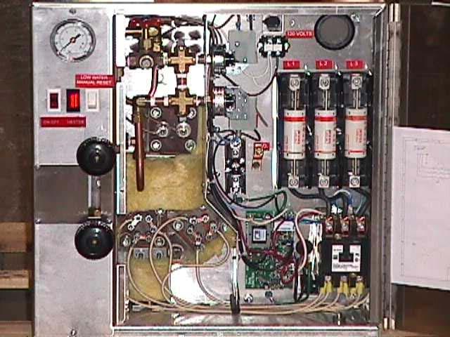
1 REIMERS ELECTRA STEAM, INC MARTINSBURG PIKE CLEAR BROOK, VA PHONE: FAX: April 01, 2001 MODELS R & RH 10 THRU 20 RB SERIES ELECTRIC STEAM BOILERS INSTALLATION, OPERATING, & MAINTENANCE INSTRUCTIONS Serial No.: READ THIS FIRST CAUTION: READ ALL INSTRUCTIONS BEFORE INSTALLATION/OPERATION. ENSURE BLOWDOWN PROPERLY/SAFELY PIPED. STAND CLEAR OF SAFETY VALVE & SCALDING STEAM. VALVES/PIPES ARE HOT WHEN UNDER PRESSURE OR HEATING UP DO NOT TOUCH MODEL: SERIAL #: Reimers Electra Steam Boilers are heated by one or more immersion-type heating elements. Automatic controls are provided to maintain pre-set operating pressure and to keep the water supply at the proper level. Safety features include automatic low-water cut-off, automatic pressure control, safety pop-off valve and visible water level gauge. Each boiler is designed to meet the requirements of ASME standards, and is individually inspected and stamped by an authorized National Board Insurance Inspector. All boilers are registered with the National Board of Boilers and Pressure Vessel Inspectors.
2 REIMERS ELECTRA STEAM, INC MARTINSBURG PIKE CLEAR BROOK, VA PHONE: FAX: April 01, 2001 OPERATING INSTRUCTIONS CAUTIONS: READ ALL INSTRUCTIONS BEFORE INSTALLATION/OPERATION. VALVES/PIPES ARE HOT WHEN UNDER PRESSURE OR HEATING UP - DO NOT TOUCH. ADJUSTMENTS: All controls have been set at the factory and should require no adjustments. MODIFICATION/MISUSE: Any modification or misuse of this unit could result in a dangerous situation. Reimers is not liable for any product that has been modified or improperly used. REGISTRATION: Most states/cities require boiler registration/inspection. Check local regulations. REPAIR: Repair of this unit must be attempted only by experienced personnel. (See Enclosed) WATER: All boilers must be blown down periodically to remove minerals, scale and other foreign matter which accumulate inside the pressure chamber. The concentration of this deposit depends in part upon the condition of the water in the area. When water if naturally soft, or has been softened chemically, blowdowns are required less often than in areas where hard water is found. Water *softeners are suggested in hard water areas to minimize the formation of hard scale on heating elements. Another factor affecting water condition is the amount of condensate, if any, that is being returned to the boiler. Since condensate is essentially clean distilled water, it contains very few impurities. If a large part of the condensate is being returned and little make-up water is used, the boiler need not be blown down as often as when little or no condensate is returned to the boiler. Chemical water treatment is not recommended for this design of electric boiler. *For details, contact a water softening company in your area. BLOWDOWN IS AN ESSENTIAL PART OF BOILER OPERATION. IT IS THE BEST PREVENTIVE MAINTENANCE YOU CAN GIVE YOUR BOILER. ENSURE A BLOWDOWN SCHEDULE IS ESTABLISHED & FOLLOWED REGULARLY. WATER LEVEL CONTROLS MUST BE KEPT CLEAN TO INSURE PROPER OPERATION. SINCE WATER QUALITY CAN VARY WATER LEVEL PROBES MUST BE INSPECTED AND CLEANED PERIODICALLY. WE SUGGEST EVERY THREE MONTHS AT A MINIMUM. INSTALLATION 1. LOCATION: Place boiler in a level position (required for proper operation of mercury tubetype controls)as close as possible to the equipment to be supplied with steam. This will allow short steam connections and minimum heat losses. Cover all steam lines with insulation. Ensure that all electrical components are in a dry location not subject to steam or water. IMPORTANT: If installing the boiler in a confined area, leave the following clearances for servicing elements. Other installation dimensions are referenced on enclosed "RECOMMENDED BOILER INSTALLATION PARAMETERS" sheet. (A) Allow 24" clearance at element end for servicing of Models 10 thru WATER SUPPLY: On models with pump and/or solenoid valve, connect incoming water supply to strainer on intake side of solenoid valve. On models furnished with condensate return tank, connect water line to makeup valve located at tank end.
3 3. STEAM OUTLET: Connect steam line of sufficient size from steam line valve to the equipment. Steam piping must be of black pipe, not galvanized. Work must be done by an experienced steamfitter. All state/local codes must be met. 4. CONDENSATE RETURN: If the condensate is to be returned by gravity (no tank & no steam trap) in a closed system, the load discharge should be at least 2 feet above the boiler water level. When applicable install steam return lines at sufficient height to allow a pitch of 2 inches to 10 feet of pipe length. To make the return connection to boiler, remove the boiler blow down valve install a tee and a close nipple and replace the blow-down valve, connect the return line with a swing check valve to the side opening of the tee with flow towards the boiler. Where a significant amount of intermittent live steam is being taken from a line over 25 to 30 ft. in length, this system is not recommended. 5. CONDENSATE RETURN SYSTEM (WITH TANK): See Instruction Supplement #1. 6. SAFETY VALVE: Safety valve is designed to discharge hot steam when the set pressure is exceeded. Ensure that the discharge port is pointing toward the back of the unit away from the operator & any aisles. If it is required that discharge piping be installed from the safety valve, the pipe must never be smaller than the valve outlet & must be rigidly supported, placing no weight on the valve itself. 7. ELECTRICAL: All wiring must be installed in accordance with the National Electric Code & any local codes that may apply. Wiring must be done by a competent, certified electrician. For this service, the N.E.C. requires supply wires rated at 125% of full load. Use only copper wire. Install a fused disconnect switch within sight of the boiler. Connect power supply to the terminals in control panel. 8. BLOWDOWN VALVE: When the blowdown valve is utilized a large volume of hot water & steam is discharged. Ensure that this valve is properly piped for this discharge. State and local codes must be met as applicable. OPERATION 1. Close the boiler drain valve, open gauge glass valves top and bottom, & open steam line valve slightly to allow air to escape. 2. Turn on main water supply. CAUTION: Be sure water supply line to boiler is OPEN before turning on main power. On models furnished with pump, never let pump run dry. 3. Throw main disconnect switch (main power supply) to ON position. This allows water to enter the boiler. On all models the water will automatically shut off when the water reaches the proper operating level. 4. Put toggle switch to the ON position and push low water manual reset. This turns on power to the heating elements. Now close the steam valve to allow pressure to build up. 5. When boiler has reached working pressure, open steam valve slowly by making 2 or 3 half turns during a period of about 2 minutes, then open the valve fully. Keep this valve open while boiler is in operation. PRESSURE ADJUSTMENT: Turn knob on pressure control (located to the left rear of the electrical box) clockwise to increase & counterclockwise to decrease. Be careful that safety valve does not lift. 6. TO SHUT OFF BOILER: Turn the toggle switch to the OFF position. Throw main power supply disconnect switch to OFF. Leave steam line open allowing pressure to drop normally and boiler to cool off slowly.
4 MAINTENANCE CAUTION: REPAIR MUST BE BY EXPERIENCED PERSONNEL. ENSURE BOILER IS COLD/DRAINED AND HAS NO PRESSURE/ELECTRIC. ALL ELECTRICAL/STEAM SAFETY PRECAUTIONS MUST BE TAKEN. 1. BLOWDOWN: Turn power off, allow pressure to drop to 5 psig, & open each blowdown valve (14) for approximately ten (10) seconds. CAUTION: STAND CLEAR OF SCALDING WATER/STEAM. ENSURE BLOWDOWN SAFELY PIPED. FREQUENCY: IN AREAS WHERE WATER IS SOFT OR HAS BEEN SOFTENED CHEMICALLY: a. When little condensate is returned BLOW DOWN ONCE EVERY WEEK. b. When a large part of the condensate returned and little make-up water is used BLOWDOWN ONCE EVERY TWO WEEKS. IN AREAS WHERE HARD WATER EXISTS: a. When little or no condensate is returned BLOW DOWN ONCE A DAY. b. When a large part of the condensate is returned and little make-up water is used BLOWDOWN ONCE EVERY WEEK. 2. PRESSURE ADJUSTMENT: (FACTORY PRESET/SELDOM REQ'D) CAUTION: STAND CLEAR OF SAFETY VALVE & SCALDING STEAM. 3. SAFETY VALVE TEST: (FREQUENCY-MINIMUM ONCE PER MONTH) CAUTION: STAND CLEAR OF SAFETY VALVE & SCALDING STEAM. NOTE: Safety valve should be tested at max.operating pressure. 1. Hold trip lever open for five seconds in order to flush off valve seat. 2. Permit valve to "slap" shut.(if leak occurs, repeat test or replace valve.) 4. ELEMENT TEST: (CONDITION) Unit will not heatup/maintain pressure, when power is on, unit is filled with water & pressure control is calling for steam. 1. VOLTAGE TEST = read rated voltage across each element. If no voltage reading, CHECK VOLTAGE BEFORE & AFTER EACH FUSE AND CHECK CONTROL VOLTAGE READING AT CONTACTOR. If voltage reads properly, GO TO STEP AMPERAGE TEST = read rated amps on each element wire. If no amp reading or unbalanced amp reading, replace element. 5. ELEMENT CLEANING: Use stiff wire brush & remove all scale/foreign matter. 6. ELEMENT REPLACEMENT: CAUTION: ENSURE BOILER IS COLD/DRAINED & HAS NO PRESSURE/ELECTRIC 1. Remove front panel of pressure vessel cabinet. 2. Disconnect and label terminal wires. 3. Remove 4 nuts from element flange and pull out heating element. 4. Clean flange surface before installing new element & gasket. 7. CONTROL CIRUCIT TEST: (CONDITION) Unit will not heatup when power is on, unit is filled with water & pressure control is calling for steam. VOLTAGE TEST = read control voltage at incoming control ciruit fuse & at each control point throughout system, i.e. low water control, hi-limit pressure control, operating pressure control (or step control if equipped), aux. low water cutoff (optional), and toggle switch. If voltage is not found at any one item in system, check out that item. 8. GAUGE GLASS REPLACEMENT: (FREQUENCY = MINIMUM ONCE PER YEAR) CAUTION: ENSURE BOILER IS COLD/DRAINED & HAS NO PRESSURE/ELECTRIC. BE CAREFUL NOT TO BREAK GLASS
5 1. Close gauge glass valves (top and bottom). 2. Open petcock on bottom fixture of drain glass. 3. Loosen nuts at top and bottom of glass. 4. Slide glass up, pull out on bottom of glass and remove. 5. Install glass by reversing above procedure. NOTE: Always install new rubber washers. 9. WATER FEED & LOW WATER CUTOFF: 1. Boiler does not take water: Check valve from city water & strainer clogging. 2. Boiler floods(cold water feed): Check solenoid for sticking. 3. Evaluate circuit board. CAUTION: USE ONLY INSULATED ELECTRICAL WIRE FOR JUMPER. DISCONNECT ELECTRICAL POWER WHEN ATTACHING JUMPER OR CLEANING PROBE. LEFT LED: Indicates pump/solenoid is on when lit. If water does not feed when LEFT LED is lit, investigate pump/solenoid. If LEFT LED does not light when water in boiler is low, remove probe wire from terminal H. If light comes on, clean probe connected to H wire. If this does not resolve problem, replace circuit board. RIGHT LED: Indicates ample water in boiler for element operation when lit. If element does not energize when RIGHT LED is lit, investigate electrical control circuit (pressure controls, fuses, contactor, etc.). If RIGHT LED does not light when water in boiler is over half full & manual reset has been pushed, jump terminals LLCO & G with insulated ground wire. If light comes on, clean probe connected to LLCO wire. If this does not resolve problem, replace circuit board. 10. PUMP MOTOR: Maintenance is not normally required on the pump or motor. 11. FUSE FAILURE: When a fuse blows, evaluate the following: SHORT CIRCUIT HAS OCCURRED: Ensure line has been cleared, the cause of short circuit removed, then install the new fuse. POOR CONTACT EXISTS: Poor contact on fuse can cause blowing. If surface that makes contact with the fuse clips is discolored, fuse has been making poor contact with the clips. Installing a larger fuse will not help. Replace the fuse holder. 12. FUSE REPLACEMENT: 1. DO NOT insert the fuse in live circuits, that will cause an arc that would cause a burr on the fuse cap which will prevent good contact with the clips. 2. If the insides of the clips and/or fuse caps are not bright and clean, brighten them with emery cloth. 3. If the fuse can be easily inserted into the spring clips or can be easily rotated after it is inserted, there is not sufficient contact pressure. Take the fuse out and draw the clips together. 4. If the clips have lost their spring, they should be replaced or clip clamps should be used. #1 for 0-30 amp/250 volt; #2 for amp/250 volt Even if clamps are used be sure that the insides of clips are bright & clean. 13. CONTACTORS: 1. Ensure contactor coil is receiving proper voltage. The req d voltage is stamped on the coil. 2. If voltage to coil is present, but contacts won't pull in, replace coil. 3. If contacts pull in, but contactor chatters: CLEAN/REPLACE CONTACT POINTS. 4. Further problems would indicate mechanical difficulties within the contactor (ie: springs, component parts). 5. Complete contactor replacement is normally the least expensive solution. NOTE: ASME DATA PLATE IS LOCATED ON END OF PRESSURE VESSEL BEHIND LABEL STAMPED WITH NATIONAL BOARD NUMBER OF UNIT.
6
7 REIMERS ELECTRA STEAM, INC MARTINSBURG PIKE CLEAR BROOK, VA PH: FAX: April 01, 2001 PARTS LIST FOR MODELS R & RH 10 THRU 20 (RB SERIES) FUSE 250V 15A VALVE GLOBE.5" FUSE 250V 60A FUSE 600V 80A CLASS J FUSE 250V 3A FUSE BLOCK 250V 30A FUSE BLOCK 250V 60A FUSE BLOCK 600V 100A 3P (FOR J FUSE) PRESSURE GAUGE 2" PRESSURE GAUGE XUC 0-30# VALVE CHECK.5" WATER GAUGE SET VALVE BALL.5" 200# CONTACTOR 50A 120V CONTACTOR 50A 240V 3P VALVE SOLENOID V VALVE SOLENOID V VALVE SAFETY.5" VALVE SAFETY.75" 15# STRAINER.375" Y VALVE BALL.5" W/LATCH RELAY SOLIDSTATE CTRL RELAY SOLIDSTATE CTRL 240V 2-WAY SWITCH MANUAL RESET NC MO PRESSURE CONTROL 91# PRESSURE CONTROL 14# PUMP 120V 1PH POSITIVE PUMP 240V 1PH 50/60 HZ GAUGE GLASS.625" X 3" GAUGE RUBBER WASHER SWITCH ILLUMINATED 120V SWITCH ILLUMINATED RED 250V LIGHT RED W/WHITE 120V LIGHT RED 250V COND TANK 11 GAL SQUARE W/VALVE ELEMENT 480V 9KW 3P ELEMENT 240V 10KW 3PH ELEMENT 240V 9KW 3PH GASKET ELEMENT

8 INSTRUCTION SUPPLEMENT NO. 1 CONDENSATE RETURN SYSTEM The following Condensate Tanks are furnished as standard equipment on Model RHC Boilers, with Serial No and up: Tank size for Models 10 thru gallons INSTALLATION 1. Connect water supply to water intake on tank. NOTE: Water supply should be turned off when boiler is not in operation. 2. Connect condensate return line from equipment to condensate return intake. 3. Pipe from vent is to be installed to outside of building, if desired. If this method is used, pipe should be the same size as vent opening. Under no condition should vent be plugged. 4. Install piping from overflow to drain. 5. Pressure reducing valve required for city water pressures in excess of 40 PSI. MAINTENANCE 1. STRAINER - should be removed and cleaned shortly after boiler has been in operation to clear away sediment which may have accumulated during start-up. This strainer should be periodically inspected and cleaned when necessary. 2. GAUGE GLASS - See boiler instructions. 4. PUMP MOTOR - Maintenance is not normally required on the pump or motor. CONDENSATE RETURN SYSTEM PARTS LIST PART# DESCRIPTION GAUGE GLASS 5/8" X 7" GAUGE GLASS FIXTURE SET STRAINER 1" SCREEN FOR STRAINER PUMP/MOTOR 120/240 1PH 1/3 HP CT MAKE-UP VALVE ASSEMBLY (1) VALVE ASSEMBLY (2) FLOAT BALL (3) GASKET (4) COMPLETE ASSEMBLY REIMERS ELECTRA STEAM, INC.
9 4407 MARTINSBURG PIKE CLEAR BROOK, VA PHONE OR FAX RECOMMENDED BOILER INSTALLATION PARAMETERS PROPER LOCATION OF EACH REIMERS BOILER WITH REGARD TO COMBUSTIBLE AND NONCOMBUSTIBLE SURFACES AND MATERIALS IS CODED ON THE BOILER NAMEPLATE. THE FOLLOWING DECODING SKETCH AND DESCRIPTION IS PROVIDED FOR THE USER INFORMATION MODEL A B C2 D EL ER JR./AR " 12" 12" 12" 12" RA " 18" 18" 13" 18" R-RH-RHC " 18" 18" 24" 18" R-RH-RHC " 24" 18" 24" 18" R-RH-RHC " 24" 18" 24" 24" R-RH-RHC " 24" 18" 36" 36" R-RH-RHC " 24" 18" 46" 46" RLP " 24" 18" 46" 46" RLP " 24" 18" 46" 18" RLP " 36" 18" 46" 46" RHP " 24" 18" 46" 46" RHP " 36" 18" 46" 46" HMR " 24" 12" 18" 12" HLR " 18" 18" 24" 18" HLR " 24" 18" 24" 18" HLR " 24" 18" 24" 24" HLR " 24" 18" 36" 36" HLR " 36" 18" 46" 18" DESCRIPTION OF DIMENSIONS & SYMBOLS A-CLEARANCE ABOVE TOP OF BOILER B-CLEARANCE FROM FRONT OF BOILER PREFIX C TO NUMERAL INDICATES SUITABILITY FOR CLOSET OR ALCOVE INSTALLATIONS. PREFIX A INDICATES SUITABILITY FOR ALCOVE BUT NOT FOR CLOSET D-CLEARANCE FROM BACK OF BOILER EL -CLEARANCE FROM LEFT SIDE OF BOILER ER- CLEARANCE FROM RIGHT SIDE OF BOILER F- INDICATES TYPE OF FLOORING: "NC" FOR NONCOMBUSTIBLE / "C" FOR COMBUSTIBLE. NUMERAL INDICATES MINIMUM CLEARANCE BELOW SUSPENDED UNITS TO COMBUSTIBLE FLOOR NOTE :IMPORTANT THE ABOVE DIMENSIONS DO NOT TAKE INTO CONSIDERATION THE PERIODIC NEED TO REMOVE THE HEATING ELEMENTS. FOR THESE ALLOWANCES PLEASE REFER TO PAGE 1,ITEM 1 OF INSTALLATION INSTRUCTIONS
REIMERS ELECTRA STEAM, INC MARTINSBURG PIKE CLEAR BROOK, VA PHONE: FAX: /17/2000
 G:\INSTR\RB20IN REIMERS ELECTRA STEAM, INC. 4407 MARTINSBURG PIKE CLEAR BROOK, VA 22624-0037 PHONE:540-662-3811 FAX:540-665-8101 10/17/2000 MODELS R & RH 10 THRU 30 RB SERIES ELECTRIC STEAM BOILERS INSTALLATION,
MODELS R & RH 24 THRU 120 ELECTRIC STEAM BOILERS
 REIMERS ELECTRA STEAM, INC. 4407 MARTINSBURG PIKE CLEAR BROOK, VA 22624-0037 PHONE: 540-662-3811 FAX: 540-665-8101 04/01/04 MODELS R & RH 24 THRU 120 ELECTRIC STEAM BOILERS INSTALLATION, OPERATING, & MAINTENANCE
Serial No.: and Up OPERATING INSTRUCTIONS MODEL AR. STEAM GENERATORS CAUTIONS:
 ELECTRA STEAM, INC. 4407 MARTINSBURG PIKE CLEAR BROOK, VA 22624 PHONE 540-662-3811, FAX 800-726-4215 Serial No.: 61107 and Up OPERATING INSTRUCTIONS MODEL AR. STEAM GENERATORS The REIMERS MODEL AR is available
REIMERS ELECTRA STEAM, INC. CAUTION:
 REIMERS ELECTRA STEAM, INC. 4407 MARTINSBURG PIKE CLEAR BROOK, VA 22624 PHONE:540-662-3811 FAX:540-665-8101 EMAIL:reimers@shentel.net READ THIS FIRST CAUTION: READ ALL INSTRUCTIONS BEFORE INSTALLATION/OPERATION.
R- RH- and RHC-Steam Boiler Models (RB-Series) Serial No and up
 Serial No and up") 4407 Martinsburg Pike Clear Brook, VA 22624 USA Electra Steam, Inc. Phone: 540-662-3811 Fax: 540-665-8101 email: Sales@reimersinc.com web: www.reimersinc.com MODEL: SERIAL #: R- RH- and RHC-Steam Boiler
4407 Martinsburg Pike Clear Brook, VA 22624 USA Electra Steam, Inc. Phone: 540-662-3811 Fax: 540-665-8101 email: Sales@reimersinc.com web: www.reimersinc.com MODEL: SERIAL #: R- RH- and RHC-Steam Boiler
Electra Steam, Inc. RLP 100k 500kW Low Pressure and RHP 100kW 500kW High Pressure Steam Boiler Models. Instructions Manual
 MODEL: Electra Steam, Inc. P.O. Box 37 Phone: 540-662-3811 4407 Martinsburg Pike Fax: 540-665-8101 Clear Brook, VA 22624 email: Sales@reimersinc.com USA web: www.reimersinc.com SERIAL #: RLP 100k 500kW
REIMERS ELECTRA STEAM, INC. INSTRUCTION MANUAL JG & JJ MODELS Serial No.:
 REIMERS ELECTRA STEAM, INC. 4407 MARTINSBURG PIKE CLEAR BROOK, VA 22624 PHONE:540-662-3811 FAX:540-665-8101 EMAIL: Sales@reimersinc.com INSTRUCTION MANUAL JG & JJ MODELS Serial No.: 60817--63570 READ THIS
REIMERS ELECTRA STEAM, INC. INSTRUCTION MANUAL JG & JJ MODELS
 REIMERS ELECTRA STEAM, INC. P.O. BOX 37 4407 MARTINSBURG PIKE CLEAR BROOK, VA 22624 PHONE:540-662-3811 FAX:540-665-8101 EMAIL: Sales@reimersinc.com INSTRUCTION MANUAL JG & JJ MODELS READ THIS FIRST CAUTION:
RX Series Steam Boiler Instructions Manual
 MODEL: Electra Steam, Inc. 4407 Martinsburg Pike Clear Brook, VA 22624 USA Phone: 540-662-3811 Fax: 540-665-8101 email: Sales@reimersinc.com web: www.reimersinc.com SERIAL #: RX36-120 Series Steam Boiler
Instructions Manual. RHP120 RHP300 High Pressure Steam Boiler Models MODEL: Electra Steam, Inc. SERIAL #:
 4407 Martinsburg Pike Clear Brook, VA 22624 USA Electra Steam, Inc. Phone: 540-662-3811 Fax: 540-665-8101 email: Sales@reimersinc.com web: www.reimersinc.com MODEL: SERIAL #: RHP120 RHP300 High Pressure
CSD-1 CRN Electra Steam, Inc. Instruction Manual for JR06 Steam Generator, JG- and JJ- Models
 ASME CSD-1 CRN Electra Steam, Inc. Instruction Manual for JR06 Steam Generator, JG- and JJ- Models RETAIN THIS OPERATING MANUAL WITH BOILER. DO NOT DISCARD READ THIS FIRST: The safeguards and instructions
R- RH- and RHC-Steam Boiler Models (RB-Series)
") MODEL: Electra Steam, Inc. P.O. Box 37 Phone: 540-662-3811 4407 Martinsburg Pike Fax: 540-665-8101 Clear Brook, VA 22624 email: Sales@reimersinc.com USA web: www.reimersinc.com SERIAL #: R- RH- and RHC-Steam
MODEL: Electra Steam, Inc. P.O. Box 37 Phone: 540-662-3811 4407 Martinsburg Pike Fax: 540-665-8101 Clear Brook, VA 22624 email: Sales@reimersinc.com USA web: www.reimersinc.com SERIAL #: R- RH- and RHC-Steam
RHP120 RHP300 Steam Boiler Series
 Electra Steam, Inc. Phone: 540-662-3811 4407 Martinsburg Pike Fax: 540-665-8101 Clear Brook, VA 22624 email: Sales@reimersinc.com USA web: www.reimersinc.com HEATING POWER kw RHP120 RHP300 Steam Boiler
Instruction Manual HWR MODEL RESISTO-FLO ELECTRIC BOILER
 Page 1 of 16 Instruction Manual HWR MODEL RESISTO-FLO ELECTRIC BOILER Page 2 of 16 FOREWORD The HWR Resisto-Flo Electric Hot Water Boiler is designed to provide a compact packaged unit requiring a minimum
Instruction Manual STR MODEL RESISTO-FLO ELECTRIC BOILER
 Page 1 of 18 Instruction Manual STR MODEL RESISTO-FLO ELECTRIC BOILER Page 2 of 18 FOREWORD The STR Resisto-Flo Electric Steam Boiler is designed to provide a compact packaged unit requiring a minimum
Series 300 VTB. Installation Instructions
 Series 300 VTB Installation Instructions Sizes 7 12 16 20 30 HP #2 Fuel Oil Gas (500 to 2500 BTU) Gas Light Oil Combination High Pressure Steam Sizes 7 thru 16 HP (125 PSI) Sizes 20 and 30 HP (150 PSI)
OPERATING AND MAINTENANCE MANUAL FOR PLATE HEAT EXCHANGER INDIRECT FIRED WATER HEATER. Electric Heater Company Base Model "BWXP"
 OPERATING AND MAINTENANCE MANUAL FOR PLATE HEAT EXCHANGER INDIRECT FIRED WATER HEATER Electric Heater Company Base Model "BWXP" HUBBELL ELECTRIC HEATER COMPANY P.O. BOX 288 STRATFORD, CT 06615 PHONE: (203)
INSTALLER: PLEASE LEAVE THIS MANUAL FOR THE OWNER S USE. Condensate Return Systems General Installation, Operation, & Service Instructions !
 Condensate Return Systems General Installation, Operation, & Service Instructions INSTALLER: PLEASE LEAVE THIS MANUAL FOR THE OWNER S USE. SAFETY INSTRUCTIONS This safety alert symbol will be used in this
L A signature series TA T N E RE O, A L L A T S IN
 signature series COMMERCIAL STEAM GENERATORS INSTALLATION, OPERATION AND MAINTENANCE MANUAL INSTALLATION MANUAL COMMERCIAL STEAM GENERATOR SIGNATURE SERIES (SS) INTRODUCTION Steam Sauna manufactures steam
southbend A MIDDLEBY COMPANY INSTALLATION AND OPERATION MANUAL CG214 (E) CG314 (E) CG414 (E) CG220 (E) CG320 (E) CG325 (E) GAS BOILERS MODELS:
 CG314 (E) CG414 (E) CG220 (E) CG320 (E) CG325 (E) GAS BOILERS MODELS:") INSTALLATION AND OPERATION MANUAL GAS BOILERS MODELS: CG214 (E) CG314 (E) CG414 (E) CG220 (E) CG320 (E) CG325 (E) southbend A MIDDLEBY COMPANY 1100 Old Honeycutt Road Fuquay-Varina, NC 27526 (919) 552-9161
INSTALLATION AND OPERATION MANUAL GAS BOILERS MODELS: CG214 (E) CG314 (E) CG414 (E) CG220 (E) CG320 (E) CG325 (E) southbend A MIDDLEBY COMPANY 1100 Old Honeycutt Road Fuquay-Varina, NC 27526 (919) 552-9161
OPERATING MANUAL. Reverse Osmosis Equipment Model: Frame Mount Vertical FMV-1 through FMV-6. Made in U.S.A.
 OPERATING MANUAL Reverse Osmosis Equipment Model: Frame Mount Vertical FMV-1 through FMV-6 Made in U.S.A. TABLE OF CONTENTS Model: Frame Mount Vertical COMPONENT IDENTIFICATION Page 1 IMAGE OF R. O. SYSTEM
Table of Contents SPECIFICATIONS Page 2. FOR THE INSTALLER Page 3. FOR THE PLUMBER Page 4. INSTALLATION Page 5. INITIAL START UP Page 6
 INTRODUCTION This service manual covers the installation, operation, maintenance and service of this ice machine. Table of Contents SPECIFICATIONS Page 2 FOR THE INSTALLER Page 3 FOR THE PLUMBER Page 4
INSTALLATION AND OPERATION MANUAL STEAM COIL BASE CONVECTION STEAMER MODEL SCX-16
 INSTALLATION AND OPERATION MANUAL STEAM COIL BASE CONVECTION STEAMER MODEL SCX-16 CROWN FOOD SERVICE EQUIPMENT LTD. 70 OAKDALE ROAD, DOWNSVIEW, (TORONTO), ONTARIO, CANADA, M3N 1V9 TELEPHONE: (416) 746-2358,
INSTALLATION and OPERATION MANUAL DIRECT STEAM KETTLES MOUNTED ON ELECTRIC BOILER BASE CABINET MODELS: EMT-6 EMT-10 EMT-12 EMT-6-6 EMT-10-6 EMT-10-10
 INSTALLATION and OPERATION MANUAL DIRECT STEAM KETTLES MOUNTED ON ELECTRIC BOILER BASE CABINET MODELS: EMT-6 EMT-10 EMT-12 EMT-6-6 EMT-10-6 EMT-10-10 CROWN FOOD SERVICE EQUIPMENT LTD. 70 OAKDALE ROAD,
OPERATING AND MAINTENANCE MANUAL FOR VERTICAL IMMERSION HEATED STEAM BOILERS. Technical Control Systems Limited MODELS "VIHS"
 OPERATING AND MAINTENANCE MANUAL FOR VERTICAL IMMERSION HEATED STEAM BOILERS Technical Control Systems Limited MODELS "VIHS" Technical Control Systems Ltd Treefield Industrial Estate Gildersome, Leeds
OPERATING AND MAINTENANCE MANUAL FOR ELECTRIC STAINLESS STEEL HEATER FOR DEIONIZED (DI) WATER ELECTRIC HEATER COMPANY BASE MODEL D
 WATER ELECTRIC HEATER COMPANY BASE MODEL D") OPERATING AND MAINTENANCE MANUAL FOR ELECTRIC STAINLESS STEEL HEATER FOR DEIONIZED (DI) WATER ELECTRIC HEATER COMPANY BASE MODEL D HUBBELL ELECTRIC HEATER COMPANY P.O. BOX 288 STRATFORD, CT 06615 PHONE:
OPERATING AND MAINTENANCE MANUAL FOR ELECTRIC STAINLESS STEEL HEATER FOR DEIONIZED (DI) WATER ELECTRIC HEATER COMPANY BASE MODEL D HUBBELL ELECTRIC HEATER COMPANY P.O. BOX 288 STRATFORD, CT 06615 PHONE:
INSTALLATION & MAINTENANCE MANUAL PVI ELECTRIC HOT WATER SUPPLY BOILER
 INSTALLATION & MAINTENANCE MANUAL PVI ELECTRIC HOT WATER SUPPLY BOILER Installation and service must be performed by a qualified service installer or service agency. IMPORTANT: THIS MANUAL CONTAINS INFORMATION
Installation and Operating Instructions ISH ELECTRIC STEAM SUPERHEATER
 Installation and Operating Instructions ISH ELECTRIC STEAM SUPERHEATER 1 Installation and Operating Instructions ISH ELECTRIC STEAM SUPERHEATER FOR YOUR SAFETY This manual supplies information on the application,
MBA Electric Steam Generator. Installation, Operation and Maintenance Manual. Products Covered by this Manual
 Installation, Operation and Maintenance Manual MBA Electric Steam Generator Model No. Generator Serial No. Power Circuit Voltage Control Circuit Voltage National Board No. Amps Phase Cy IMPORTANT: This
Unfired Steam Generators (Series RB) Installation, Operation and Maintenance
 Installation, Operation and Maintenance") Unfired Steam Generators (Series RB) Installation, Operation and Maintenance Horizontal USG Vertical USG 534-EN Please read and save these instructions Disclaimers This Installation, Operation, and Maintenance
Unfired Steam Generators (Series RB) Installation, Operation and Maintenance Horizontal USG Vertical USG 534-EN Please read and save these instructions Disclaimers This Installation, Operation, and Maintenance
SERVICE MANUAL. Bradford White ElectriFLEX HD (Heavy Duty) Commercial Electric Water Heater CEHD SERIES Immersion Thermostat Models
 Commercial Electric Water Heater CEHD SERIES Immersion Thermostat Models") Bradford White ElectriFLEX HD (Heavy Duty) Commercial Electric Water Heater CEHD SERIES Immersion Thermostat Models SERVICE MANUAL Troubleshooting Guide and Instructions for Service (To be performed ONLY
Bradford White ElectriFLEX HD (Heavy Duty) Commercial Electric Water Heater CEHD SERIES Immersion Thermostat Models SERVICE MANUAL Troubleshooting Guide and Instructions for Service (To be performed ONLY
Water Boilers ME10EN, ME15EN. Table of Contents
 Water Boilers ME10EN, ME15EN Operator Manual Model ME15EN Model ME10EN Safety Information...2 Rough-In Drawing...3 Installation...4 Priming...5 Cleaning...5 Table of Contents Adjustments...6 Maintenance...7
Installation, Operation and Maintenance
 Bulletin No. 534 Installation, Operation and Maintenance Unfired Steam Generators (Series RB) Horizontal USG Vertical USG Disclaimers This Installation, Operation, and Maintenance Manual is intended to
INSTALLATION, OPERATION AND MAINTENANCE MANUAL FOR COMMERCIAL INDIRECT POWERED WATER HEATER
 INSTALLATION, OPERATION AND MAINTENANCE MANUAL FOR COMMERCIAL INDIRECT POWERED WATER HEATER ELECTRIC HEATER COMPANY BASE MODEL T Edition 0 HUBBELL ELECTRIC HEATER COMPANY P.O. BOX 88 STRATFORD, CT 0665
SECTION DOMESTIC WATER HEATERS
 SECTION 223500 PART 1 - GENERAL 1.1 RELATED DOCUMENTS A. Drawings and general provisions of the Contract, including General and Supplementary Conditions and Division 01 Specification Sections, apply to
INSTALLATION, OPERATING & MAINTENANCE INSTRUCTIONS FOR 350 SERIES CIRCULATION HEATERS
 INDEECO Circulation Heaters are designed to provide years of trouble free operation if properly installed and maintained. Please read and follow these instructions for installing and maintaining the heater.
INSTALLATION AND SERVICE MANUAL
 INSTALLATION AND SERVICE MANUAL Electric Power Water Heater 12kW 162kW NOTE: retain this manual for future reference Installation and service must be performed by Qualified Service Personnel Only. WARRANTY:
Parts Manual. Counter Type Electric Convection Steamer. Series: SteamCraft Models 21CET East 179 th Street Cleveland, Ohio 44110
 Parts Manual Counter Type Electric Convection Steamer Series: SteamCraft Models 21CET8 1333 East 179 th Street Cleveland, Ohio 44110 Phone: (216) 481-4900 1-800-338-2204 Fax: (216) 481-3782 www.clevelandrange.com
CER Series 2. Installation Instructions. Electric-Hydronic Boilers. Installer
 CER Series 2 Electric-Hydronic Boilers Installation Instructions Installer Read all instructions before installing. Follow all instructions in proper order to prevent personal injury or death. Consider
ME SERIES ELECTRICALLY OPERATED BOILERS INSTALLATION - OPERATION - MAINTENANCE MODELS
 ME SERIES ELECTRICALLY OPERATED BOILERS INSTALLATION - OPERATION - MAINTENANCE MODELS M24E M36E Telephone: (802) 658-6600 Fax: (802)864-0183 www.marketforge.com PN 14-0309 Rev G (11/17) 2017 - Market Forge
The Danger signal indicates an immediately hazardous situation which, if not avoided, will result in death or serious injury.
 The Danger signal indicates an immediately hazardous situation which, if not avoided, will result in death or serious injury. The Warning signal alerts you to potential hazards or unsafe practices which,
PS-3E AND PS-6E ELECTRIC CONVECTON STEAMERS PARTS AND SERVICE MANUAL
 PS-3E AND PS-6E ELECTRIC CONVECTON STEAMERS PARTS AND SERVICE MANUAL EFFECTIVE AUGUST 1, 2014 Superseding All Previous Parts Lists. The Company reserves the right to make substitution in the event that
CHLORIDE GASES CHLORIDES
 Note: Always have this machine s model and serial number (printed on the first page of this document) ready when calling Consolidated for service or parts. WARNING If this sterilizer s chamber is constructed
Hot Water Boilers 810(E), 815(E), 830(E), 850(E) Table of Contents
, 815(E), 830(E), 850(E) Table of Contents") Hot Water Boilers 810(E), 815(E), 830(E), 850(E) Operator Manual Model 810(E) Safety Information...2 Rough-In Drawing...3 General Description...4 Installation...4 Priming...5 Cleaning...5 Table of Contents
Hot Water Boilers 810(E), 815(E), 830(E), 850(E) Operator Manual Model 810(E) Safety Information...2 Rough-In Drawing...3 General Description...4 Installation...4 Priming...5 Cleaning...5 Table of Contents
Armstrong Flo-H2O Water to Water Instantaneous Heater Installation and Maintenance & Operation
 Armstrong Flo-H2O Water to Water Instantaneous Heater Installation and Maintenance & Operation AY-414 This bulletin should be used by experienced personnel as a guide to the installation and maintenance
CROWN. Boiler Co. Santa-Fe Series. Hydronic Air Handlers INSTALLATION, OPERATION & MAINTENANCE INSTRUCTIONS
 CROWN Boiler Co Santa-Fe Series Hydronic Air Handlers INSTALLATION, OPERATION & MAINTENANCE INSTRUCTIONS These instructions must be affixed on or adjacent to the air handler Models: SAC049A20 SAC059A25
THERMAPHASE INSTALLATION AND OPERATING INSTRUCTIONS
 Page 1 of 10 THERMAPHASE INSTALLATION AND OPERATING INSTRUCTIONS Purpose of Manual The purpose of this manual is to provide operating, servicing and repair instructions for the Summit standard models ThermaPhase
Series 47 and 247 Mechanical Water Feeders. Series 47-2 and Combination Mechanical Water Feeder/Low Water Cut-Off ! WARNING
 Series 47 and 247 Mechanical Water Feeders McDonnell & Miller Installation & Maintenance Instructions MM-316(C) Series 47-2 and 247-2 Combination Mechanical Water Feeder/Low Water Cut-Off Series 47 Water
CHILLER. Operator s & Installation Manual
 CHILLER MODELS: CH1001-A Operator s & Installation Manual Release Date: August 9, 2002 Publication Number: 620914301 Revision Date: May 6, 2010 Revision: E Visit the IMI Cornelius web site at www.cornelius.com
LATTNER BOILER COMPANY 9.5 HP Low-NOx Installation and Start-Up Checklist for Dry Cleaners
 1 1. General Installation Information (to be completed by technician) Date installed: Location (city & state): Cleaner s name: National Board number (boiler): Installed by (company): Installed by (technician):
ES Series Electric Humidifier
 Read and Save These Instructions Standard Water ES Series Electric Humidifier Installation Instructions Operation and Maintenance Manual ETL LISTED HUMIDIFIER Our results are comforting Form No: ESOM-08-08
ERGOMAX 7 INSTALLATION
 ERGOMAX 7 INSTALLATION INSTALLATION MUST CONFORM TO LOCAL CODES 1. WITH HYDRONIC BOILERS All ERGOMAX 7 units must be installed vertically. Adjustable feet for levelling are provided. PRESSURE RELIEF VALVE:
INSTALLATION & MAINTENANCE MANUAL FOR QuickDraw
 INSTALLATION & MAINTENANCE MANUAL FOR QuickDraw SEMI-INSTANTANEOUS ENERGY: STEAM TO WATER U-TUBE SINGLE-WALL & DOUBLE-WALL HEAT EXCHANGERS FLOOR DRAIN Typical Construction Figure 34-1 FLOOR DRAIN 1. U-tube
Niles Steel Tank Hot Water Generator Installation and Operation Manual
 Niles Steel Tank Hot Water Generator Installation and Operation Manual Contents: Contents 1 Hazard definitions 1 1. General Information.... 2 Availability... 3 Optional Control Packages... 5 2. Installation....
ECOJET EJ-10E & EJ-7E ELECTRIC CONVECTION STEAMER W/TWIN GENERATORS PARTS AND SERVICE MANUAL
 ECOJET EJ-10E & EJ-7E ELECTRIC CONVECTION STEAMER W/TWIN GENERATORS PARTS AND SERVICE MANUAL EFFECTIVE JULY 31, 2014 Superseding All Previous Parts Lists. The Company reserves the right to make substitution
!!! Sample Written Program For Your Company. For BOILER SAFETY. Provided By:!!!
 Sample Written Program For Your Company For BOILER SAFETY Provided By: P.O. Box 2136 Slidell, LA 70458 Phone: 985-781-1444 Fax: 985-781-1446 Email: info@se-safety.com Purpose Boiler Safety Program The
ES & HU Installation, Operation and Maintenance Manual
 ES & HU Installation, Operation and Maintenance Manual Model No. Boiler Serial No. National Board No. Safety Valve Set Pressure PSIG Power Circuit Voltage Control Circuit Voltage Amps Phase HZ Steam Outlet
RENEWAL PARTS IDENTIFICATION. Type TTUH and TTUH-CO URN Heaters. Dimensions (In.) Extends. Model Volts kw W/In 2 A B C D
 Extends. Model Volts kw W/In 2 A B C D") Chromalox Installation, Operation and RENEWAL PARTS IDENTIFICATION DIVISION DATE SALES REFERENCE (Supersedes PD00-1) OCTOBER, 000 SECTION TTUH PD00-15 161-0815-001 Type TTUH and TTUH-CO URN Heaters TTUH-0A
Chromalox Installation, Operation and RENEWAL PARTS IDENTIFICATION DIVISION DATE SALES REFERENCE (Supersedes PD00-1) OCTOBER, 000 SECTION TTUH PD00-15 161-0815-001 Type TTUH and TTUH-CO URN Heaters TTUH-0A
AquaSaver DISPOSER CONTROL CENTER Installation Manual. Model AS-101K
 AquaSaver DISPOSER CONTROL CENTER Installation Manual Model AS-1K The Danger signal indicates an immediately hazardous situation which, if not avoided, will result in death or serious injury. The Warning
EXTREME HP-1 Reverse Osmosis System
 EXTREME HP-1 Reverse Osmosis System Leader Evaporator Co., Inc. 49 Jonergin Drive Swanton, VT 05488 Tel: 802-868-5444 www.leaderevaporator.com TABLE OF CONTENTS INTRODUCTION... 4 THEORY OF OPERATION...
SuperKlean Washdown Products
 February 2012 DURAMIX 8000 INSTALLATION AND MAINTENANCE INSTRUCTIONS **DO NOT THROW AWAY AFTER INSTALLATION** **SAVE AND DISPLAY PROMINENTLY WHERE THIS EQUIPMENT IS USED** WARNING HIGH PRESSURE AND HOT
Installation and Operation Instructions. Versa. Screw Plug Oil & Water Immersion Heater. PD January 2018
 Installation and Operation Instructions Versa TM Screw Plug Oil & Water Immersion Heater 1 PD449-2 161-306451-003 January 2018 B 6" 1-13/16 Cold (Ref.) 9-1/8" 2-3/4 Min. Hole Size 6" 7-7/8" Thermowell
Series 1140 and 1141 Temperature Regulators
 Hoffman Specialty Installation & Maintenance Instructions HS-504(E) Series 1140 and 1141 Temperature Regulators! CAUTION FOLLOW ALL INSTALLATION AND OPERATING INSTRUCTIONS. TURN OFF WATER OR STEAM BEFORE
Circulating Oil Temperature Control System
 Installation & Operation Manual Circulating Oil Temperature Control System i PQ451 161-123417-037 February 2019 Table of Contents Contents Page Number Section 1 Getting Started... 1 Section 2 Installation...
MODEL A18 SOLVENT RECOVERY SYSTEMS (EXPLOSION PROOF UNITS)
") MODEL A18 SOLVENT RECOVERY SYSTEMS (EXPLOSION PROOF UNITS) FOR PROPER AND SAFE USE OF THIS CHEMCHAMP EQUIPMENT, PLEASE FOLLOW THIS DOCUMENT AND LOCAL AUTHORITY. KEEP THIS DOCUMENT FOR FUTURE REFERENCE.
MODEL A18 SOLVENT RECOVERY SYSTEMS (EXPLOSION PROOF UNITS) FOR PROPER AND SAFE USE OF THIS CHEMCHAMP EQUIPMENT, PLEASE FOLLOW THIS DOCUMENT AND LOCAL AUTHORITY. KEEP THIS DOCUMENT FOR FUTURE REFERENCE.
INSTRUCTION MANUAL DN0136 REVISION D
 INSTRUCTION MANUAL DN0136 REVISION D PIPING (Returns) Gravity return lines from system must be properly pitched down to unit inlet. Returns must also be trapped to prevent steam entry into the unit. An
model NO. LSS GALLON SKID MOUNTED HIGH PRESSURE SPRAYER ASSEMBLY / OPERATION INSTRUCTIONS / PARTS
 000 model NO. LSS- 00 GALLON SKID MOUNTED HIGH PRESSURE SPRAYER ASSEMBLY / OPERATION INSTRUCTIONS / PARTS Part number and descriptions can be obtained from the illustrated parts list section of this manual.
Statement of Responsibilities
 Statement of Responsibilities This document is for use by experienced and trained Qualified Cleveland Range, LLC Authorized Service Representatives who are familiar with both the safety procedures, and
Statement of Responsibilities
 Statement of Responsibilities This document is for use by experienced and trained Qualified Cleveland Range, LLC Authorized Service Representatives who are familiar with both the safety procedures, and
R Series B & T2 Model
 FRONT R Series B & T2 Model Fan Forced Wall Heaters 4-1/4 (108mm) NOTE: Knockouts in top same dimensions 3-1/4 3-1/4 (108mm) (108mm) as bottom 16-7/8 (429mm) 13-7/8 (352mm) BOTTOM 13-7/8 (352mm) 7-3/4
INSTALLATION, OPERATION AND MAINTENANCE MANUAL FOR POINT OF USE STEAM FIRED WATER HEATER ELECTRIC HEATER COMPANY BASE MODEL PS
 INSTALLATION, OPERATION AND MAINTENANCE MANUAL FOR POINT OF USE STEAM FIRED WATER HEATER ELECTRIC HEATER COMPANY BASE MODEL PS Edition 2011 HUBBELL ELECTRIC HEATER COMPANY P.O. BOX 288 STRATFORD, CT 06615
EQUIPMENT PRE-STARTUP AND STARTUP CHECKLIST TEL NO: ORDER NO: CONTRACT NO:
 Supersedes: (316) Form QTC4-CL2 (617) MODEL QTC4 EQUIPMENT PRE-STARTUP AND STARTUP CHECKLIST CUSTOMER: ADDRESS: PHONE: JOB NAME: LOCATION: CUSTOMER ORDER NO: TEL NO: ORDER NO: CONTRACT NO: CHILLER MODEL
! WARNING. McDonnell & Miller Installation & Maintenance Instructions MM-315(C)
") Models 51, 51-S and 53 Boiler Water Feeders Models 51-2, 51-S-2 and 53-2 Feeder Cut-Off Combinations McDonnell & Miller Installation & Maintenance Instructions MM-315(C) OPERATION Maximum Water Supply
Models 51, 51-S and 53 Boiler Water Feeders Models 51-2, 51-S-2 and 53-2 Feeder Cut-Off Combinations McDonnell & Miller Installation & Maintenance Instructions MM-315(C) OPERATION Maximum Water Supply
FUEL OIL DAY TANKS. SST Level Controller: UL 508 LISTED
 FUEL OIL DAY TANKS SST Series - Engineering Submittal SST Series - Advanced Line Day Tanks Construction: UL 142 aboveground steel tank all seam welded, square, atmospheric tank of heavy gauge steel with
Installation, Operation & Maintenance Instructions
 Installation, Operation & Maintenance Instructions 313 OVERFLOW TRAP TALE OF CONTENTS Overview... Cover General Information... Cover Installation... 4 Operation... 4 Maintenance... 4 Float all Level Test
Domestic Pump Vacuum and Boiler Feed Units Series VCMD TM INSTRUCTION MANUAL DN0137 REVISION F
 Domestic Pump Vacuum and Boiler Feed Units Series VCMD TM INSTRUCTION MANUAL DN0137 REVISION F DESCRIPTION The Series VCMD family of units consists of various combinations of boiler feed units combined
Form 2143 Date: 4/3/03 Repl: 2/1/99 BRYAN STEAM LLC. Installation and Operating Service Manual BOILER FEED SYSTEM
 0 Form 2143 Date: 4/3/03 Repl: 2/1/99 BRYAN STEAM LLC Installation and Operating Service Manual BOILER FEED SYSTEM INSTALLATION AND OPERATION SERVICE MANUAL BOILER FEED SYSTEM Bryan Steam LLC 783 North
OWNERS' GUIDE PRECISION WATER SYSTEMS WATER DISTILLER. Water Systems FOR MODELS: PWS MANUFACTURED BY:
 PREC SION Water Systems OWNERS' GUIDE FOR MODELS: PWS 45-75 MANUFACTURED BY: PRECISION WATER SYSTEMS WATER DISTILLER PRECISION DESIGN & MANUFACTURING INC. 9024 100 STREET WESTLOCK, ALBERTA, CANADA, T7P
MODEL YVAA EQUIPMENT PRE-STARTUP AND STARTUP CHECKLIST CUSTOMER: LOCATION: ADDRESS: CUSTOMER ORDER NO: PHONE: JCI CONTRACT NO: JOB NAME:
 Supersedes: 201.28-CL2 (817) Form 201.28-CL2 (1017) MODEL YVAA EQUIPMENT PRE-STARTUP AND STARTUP CHECKLIST CUSTOMER: LOCATION: ADDRESS: PHONE: JOB NAME: CUSTOMER ORDER NO: JCI CONTRACT NO: CHILLER MODEL
STEAMPRO. Steam Generator Troubleshooting and Service Guide
 STEAMPRO Steam Generator Troubleshooting and Service Guide TABLE OF CONTENTS Page PREFACE... 1 I. STEAMPRO STEAM GENERATOR SYSTEM...2 II. PLUMBING AND ELECTRICAL...3-4 III. SYSTEM OVERVIEW... 5-10 IV.
J120 STEAM BOOSTER INSTALLATION, OPERATION, AND SERVICE MANUAL J120 STEAM BOOSTER. J120 Steam Booster Manual D
 INSTALLATION, OPERATION, AND SERVICE MANUAL J120 STEAM BOOSTER J120 STEAM BOOSTER J120 Steam Booster Manual REVISION HISTORY Revision Letter Revision Date Made by Applicable ECNs Details A 10-27-04 CBW
Installation, Operation, and Maintenance Manual CEMLINE CORPORATION
 $7.50 Installation, Operation, and Maintenance Manual CEMLINE CORPORATION Unfired Steam Generators (USG Series) Horizontal USG Vertical USG CEMLINE CORPORATION P. O. Box 55, Cheswick, PA, 15024 Phone:
Sussman Boilers: ES, SSB & HU Installation, Operation and Maintenance Manual
 Sussman Boilers: ES, SSB & HU Installation, Operation and Maintenance Manual Model No. Boiler Serial No. National Board No. Safety Valve Set Pressure PSIG Power Circuit Voltage Control Circuit Voltage
Evaporative Cooling products
 user manual Evaporative Cooling products OPERATION - MAINTENANCE Z0582995_A ISSUED 06/2017 READ AND UNDERSTAND THIS MANUAL PRIOR TO OPERATING OR SERVICING THIS PRODUCT general information Note Recold
INSTRUCTIONS FOR TAL SERIES VACUUM HOPPER LOADER
 INSTRUCTIONS FOR TAL SERIES VACUUM HOR LOADER TAL-15U 150 LBS PER HOUR MAGNETIC LEVEL SWITCH TAL-3U-E 450 LBS PER HOUR SIGHT GLASS WITH PROXIMITY LEVEL SWITCH Proportional Dual Feed Valve Available TAL-6U
PARTS MANUAL. American Dish Service ADS HIGH TEMP SINGLE RACK DISHMACHINE MODEL: HT Blake Street Edwardsville, Kansas (913)
") EFFECTIVE: MAY, 2014 ADS HIGH TEMP SINGLE RACK DISHMACHINE MODEL: PARTS MANUAL 900 Blake Street Edwardsville, Kansas 66111 (913)-422-3700 05/08 The American Dish Service part numbers contained in this
EFFECTIVE: MAY, 2014 ADS HIGH TEMP SINGLE RACK DISHMACHINE MODEL: PARTS MANUAL 900 Blake Street Edwardsville, Kansas 66111 (913)-422-3700 05/08 The American Dish Service part numbers contained in this
Installation. 15 W. Undercounter/Freestanding Ice Machine FGIM515 / CFGIM515 FPIM515 / CFPIM515
 Installation 15 W. Undercounter/Freestanding Ice Machine FGIM515 / CFGIM515 FPIM515 / CFPIM515 TABLE OF CONTENTS Warnings & Important Safety Instructions 3 Dimensions (Professional) 5 Dimensions (Custom
TECHNICAL INFORMATION T1500 Series Clothes Dryers
 TECHNICAL INFORMATION T1500 Series Clothes Dryers 2003 Miele - Table of Contents 1.0 CONSTRUCTION & DESIGN 1.1 Appliance Overview - Vented 1 1.2 Appliance Overview Condenser Models 2 1.3 Controls Overview
EXTREME 1 Reverse Osmosis System
 EXTREME 1 Reverse Osmosis System Leader Evaporator Co., Inc. 49 Jonergin Drive Swanton, VT 05488 Tel: 802-868-5444 www.leaderevaporator.com TABLE OF CONTENTS INTRODUCTION... 4 THEORY OF OPERATION... 4
Installation & Operating Guide
 5-036 HOT WATER TANK Installation & Operating Guide Read all instructions thoroughly. Keep this guide for future reference. Proof of purchase is required for Warranty. Staple receipt or proof of purchase
ALDRICH COMPANY THREE PASS FIRETUBE BOILER CLASSIC SERIES OPERATING & MAINTENANCE MANUAL
 ALDRICH COMPANY THREE PASS FIRETUBE BOILER CLASSIC SERIES OPERATING & MAINTENANCE MANUAL ALDRICH COMPANY 341 EAST WILLIAMS ST WYOMING, IL 61491 PH: 309-695-2311 FAX: 309-695-5779 1 General Information:
Installation Manual CARBONATOR With Plain-Water Booster
 CORNELIUS INC One Cornelius Place Anoka, MN 55303-6234 Telephone (800) 238-3600 Facsimile (763) 422-3246 Installation Manual CARBONATOR With Plain-Water Booster IMPORTANT: It is the responsibility of the
Blowdown Separator & Aftercoolers
 Blowdown Separator & Aftercoolers Installation, Operation, & Maintenance Thermaflo Engineering PO Box 473639, Charlotte, NC 28247 Blowdown Separator & Aftercoolers Installation, Operation, & Maintenance
Installation, Operation and Maintenance Guide AP3900 Series Thermostatic Mixing Valves
 Note: Please provide valve serial number (stamped on cover of valve) when ordering parts. Hot Water Tempered Water Outlet Cold Water Tempered Water Outlet Redundant Thermostatic Mixing Valve Hot Water
LC Series - Light Commercial Pump Station Installation and Operation Manual
 LC Series - Light Commercial Pump Station Installation and Operation Manual Please keep this manual with the pump station Content Rain Bird LC Series Overview... Safety Instruction... Operation... 3 Pump
EFFECTIVE: MAY, American Dish Service ADS MODEL: ASQ GLASSWASHER PARTS MANUAL. 900 Blake Street Edwardsville, Kansas (913) /08
 /08") EFFECTIVE: MAY, 2014 American Dish Service ADS MODEL: ASQ GLASSWASHER PARTS MANUAL 900 Blake Street Edwardsville, Kansas 66111 (913)422-3700 05/08 The American Dish Service part numbers contained in this
EFFECTIVE: MAY, 2014 American Dish Service ADS MODEL: ASQ GLASSWASHER PARTS MANUAL 900 Blake Street Edwardsville, Kansas 66111 (913)422-3700 05/08 The American Dish Service part numbers contained in this
Installation and Maintenance Manual Please retain this manual for future reference.
 342 N. Co. Rd. 400 East Valparaiso, IN 46383 219-464-8818 Fax 219-462-7985 www.heatwagon.com Installation and Maintenance Manual Please retain this manual for future reference. Electric Construction Heaters
Cool IR. Model C104 - Cooling System. Instruction Manual
 Cool IR Model C104 - Cooling System Instruction Manual February 26, 2015 Research, Inc. USA Ph: 952.949-9009 Fax: 952.949-9559 tsdsales@researchinc.com www.researchinc.com Table of Contents List of Figures...
INSTRUCTION MANUAL with Replacement Parts
 INSTRUCTION MANUAL with Replacement Parts MODEL FD500 FOOD WASTE DISPOSERS (INCLUDES MOTOR PARTS) ML-18978 A product of HOBART CORPORATION 701 S. RIDGE AVENUE TROY, OHIO 45374-0001 FORM 11394 Rev. G (10-98)
PARTS MANUAL. American Dish Service ADS CONVEYOR DISHWASHER MODELS: ADC-44 L-R/R-L EFFECTIVE: SEPTEMBER 1, 2001
 EFFECTIVE: SEPTEMBER 1, 2001 ADS CONVEYOR DISHWASHER MODELS: ADC-44 L-R/R-L PARTS MANUAL 900 Blake Street Edwardsville, Kansas 66111 (913)422-3700 211-0044L-R / 212-0044R-L ADC-44 Conveyor Dishwasher 2