GAS GRIDDLE RANGES ELECTRIC OVEN
|
|
|
- Thomasine Shaw
- 6 years ago
- Views:
Transcription


1 INSTALLATION AND OPERATION MANUAL GAS GRIDDLE RANGES ELECTRIC OVEN GPE506 GPE56 GPE508 GPE58 For use in GB & IE
2 MANUFACTURED BY Moffat Limited Rolleston 7675 New Zealand INTERNATIONAL CONTACTS AUSTRALIA Moffat Pty Limited Web: E.Mail: Main Office: (tel) +61 (03) (fax) +61 (03) Service: (tel): Spares: (tel): Customer Service: (tel): (fax): CANADA Serve Canada Web: E.Mail: Sales: Service: (tel): (Toll Free) (tel): (Toll Free) NEW ZEALAND Moffat Limited Web: E.Mail: Main Office: (tel): UNITED KINGDOM Blue Seal Web: E.Mail: Sales: (tel): (fax): Spares: (tel): (fax): Service: (tel): (fax): UNITED STATES Moffat Web: Sales: Service: (tel): (Toll Free) (tel): (fax): (tel): (Toll Free) (tel): (fax): REST OF WORLD Moffat Limited Web: E.Mail: The reproduction or copying of any part of this manual by any means whatsoever is strictly forbidden unless authorized previously in writing by the manufacturer. In line with policy to continually develop and improve its products, Moffat Ltd. reserves the right to change the specifications and design without prior notice. Copyright Moffat Ltd. December 2014.
3 Contents Blue Seal Gas Griddle Ranges - Electric Oven GPE506 Gas Griddle Range, Electric Static Oven - 900mm. GPE56 Gas Griddle Range, Electric Convection Oven - 900mm. GPE508 Gas Griddle Range, Electric Static Oven mm. GPE58 Gas Griddle Range, Electric Convection Oven mm. Introduction... 2 Specifications... 3 Model Numbers Covered in this Specification Gas Supply Requirements Electrical Supply Requirements Electrical Connection Dimensions... 7 Installation... 8 Installation Requirements Unpacking Location Clearances Assembly Gas Connection Electrical Connection Commissioning Operation Operation Guide Description of Controls Lighting the Griddle - Pilot Burners Lighting the Griddle - Main Burners Re-setting the Overtemp Device (All UK and Optional Non UK Models) Turning Off the Griddle Main Burner / Pilot Burner Oven Cleaning and Maintenance General After Each Use Daily Cleaning Weekly Cleaning Periodic Maintenance Fault Finding Wiring Schematics Gas Conversion and Specifications Conversion Procedure Gas Specifications Replacement Parts List... 26
4 Introduction We are confident that you will be delighted with your BLUE SEAL Gas Griddle Range - Electric Oven and it will become a most valued appliance in your commercial kitchen. To ensure you receive the utmost benefit from your new Blue Seal appliance, there are two important things you can do. Firstly: Please read the instruction book carefully and follow the directions given. The time taken will be well spent. Secondly: If you are unsure of any aspect of the installation, instructions or performance of your appliance, contact your BLUE SEAL dealer promptly. In many cases a phone call could answer your question. CE Only: These instructions are only valid if the country code appears on the appliance. If the code does not appear on the appliance, refer to the supplier of this appliance to obtain the technical instructions for adapting the appliance to the conditions for use in that country. Warning IMPROPER INSTALLATION, ADJUSTMENT, ALTERATION, SERVICE OR MAINTENANCE CAN CAUSE PROPERTY DAMAGE, INJURY OR DEATH. READ THE INSTALLATION, OPERATING AND MAINTENANCE INSTRUCTIONS THOROUGHLY BEFORE INSTALLING OR SERVICING THIS APPLIANCE. Warning INSTRUCTIONS TO BE FOLLOWED IN THE EVENT THE USER SMELLS GAS ARE TO BE POSTED IN A PROMINENT LOCATION. THIS INFORMATION SHALL BE OBTAINED BY CONSULTING THE LOCAL GAS SUPPLIER. Warning THE OPERATOR MUST TAKE GREAT CARE TO USE THE EQUIPMENT SAFELY TO GUARD AGAINST RISK OF FIRE AND INJURY. THE APPLIANCE MUST NOT BE LEFT ON, UNATTENDED. IT IS RECOMMENDED THAT A REGULAR INSPECTION IS MADE BY A COMPETENT SERVICE PERSON TO ENSURE CORRECT AND SAFE OPERATION OF YOUR APPLIANCE IS MAINTAINED. DO NOT STORE OR USE GASOLINE OR OTHER FLAMMABLE VAPOURS OR LIQUIDS IN THE VICINITY OF THIS OR ANY OTHER APPLIANCE. DO NOT SPRAY AEROSOLS IN THE VICINITY OF THIS APPLIANCE WHILE IT IS IN OPERATION. Caution This appliance is for professional use and is only to be used by qualified persons. Only authorised service persons are to carry out installation, servicing or gas conversion operations. Components having adjustments protected (e.g. paint sealed) by the manufacturer should not be adjusted by the user / operator. DO NOT operate the appliance without the legs supplied fitted. 2
5 Specifications Model Numbers Covered in this Specification GPE506 Gas Griddle Range, Electric Static Oven - 900mm. GPE56 Gas Griddle Range, Electric Convection Oven - 900mm. GPE508 Gas Griddle Range, Electric Static Oven mm. GPE58 Gas Griddle Range, Electric Convection Oven mm. General A commercial heavy duty, fully modular, gas fired griddle / electric oven range using a thermostatic burner system on the griddle and fitted with 3 bar even heat aluminised steel burners with full pilot and flame failure protection and piezo ignition to each burner. All UK models and optional Non UK models are fitted with an overtemp device which isolates the gas supply to burners should gas control system or thermostat malfunction, thus preventing overheating of the griddle. The griddle uses a 20mm thick griddle plate with the option of either ribbed or chromed mirror plate options and is available in either 900 mm or 1200mm griddle size. With a heavy duty, high efficiency electric static or convection oven options, fitted with a 900mm, 6.5 kw electric static oven and a 6.6 kw Convection Oven created for compact modular kitchens. Both ovens are fitted with 4.5 kw bottom elements and 2.0 kw top element. The Convection Oven is fitted with a 100W oven fan motor. The appliance is built to facilitate easy cleaning and maintenance with all parts being front accessible once appliance is installed. 3
6 Specifications Gas Supply Requirements - Australia Natural Gas LP Gas (Propane) GPE506/GPE56 GPE508/GPE58 GPE506/GPE56 GPE508/GPE58 Input Rating (N.H.G.C.) 80 MJ/hr 108 MJ/hr 80 MJ/hr 108 MJ/hr Supply Pressure kpa kpa Burner Operating Pressure (*) 0.90 kpa 2.6 kpa Gas Connection ¾ BSP Male - New Zealand Only: Natural Gas LP Gas GPE506/GPE56 GPE508/GPE58 GPE506/GPE56 GPE508/GPE58 Input Rating (N.H.G.C.) 80 MJ/hr 108 MJ/hr 80 MJ/hr 108 MJ/hr Supply Pressure kpa kpa Burner Operating Pressure (*) 0.90 kpa 2.6 kpa Gas Connection ¾ BSP Male - UK Only: Category: II 2H3P (20, 37). Flue Type: A 1. Natural Gas (G20) Propane (G31) GPE506/GPE56 GPE508/GPE58 GPE506/GPE56 GPE508/GPE58 Heat Input (nett) 21 kw 28.5 kw 21 kw 28.5 kw Gas Rate (nett) 2.22 m 3 /hr 3.02 m 3 /hr 1.63 kg/hr 2.21 kg/hr Supply Pressure 20 mbar 37 mbar Burner Operating Pressure (*) 8.2 mbar 26 mbar Gas Connection 3 / 4 BSP Male * - Measure burner operating pressure at gas control valve outlet test point with one burner operating at High setting. Operating pressure is ex-factory set, through the appliance regulator and not to be adjusted, apart from when converting between gases, if required. (Refer to Gas Conversion section for details). 4
7 Specifications - All Other Markets Natural Gas Town Gas (**) GPE506/GPE56 GPE508/GPE58 GPE506/GPE56 GPE508/GPE58 Input Rating (N.H.G.C.) 80 MJ/hr 108 MJ/hr 80 MJ/hr 108 MJ/hr Supply Pressure kpa kpa Burner Operating Pressure (*) 0.90 kpa 0.45 kpa Gas Connection ¾ BSP Male LP Gas (Propane) Butane GPE506/GPE56 GPE508/GPE58 GPE506/GPE56 GPE508/GPE58 Input Rating (N.H.G.C.) 80 MJ/hr 108 MJ/hr 80 MJ/hr 108 MJ/hr Supply Pressure kpa kpa Burner Operating Pressure (*) 2.6 kpa 2.6 kpa Gas Connection ¾ BSP Male (*) NOTE: (*) Measure burner operating pressure at at gas valve outlet test point with burner operating at 'High Flame' setting. NAT, LPG & Butane Only - Operating pressure is ex-factory set and is not to be adjusted, unless when converting between gases, if required. (**) TOWN GAS Only - Adjust burner operating pressure using adjustable gas regulator supplied. Refer to Gas Conversion and Specifications' section in this manual for further details. Gas Connection Gas supply connection point is located 130mm from right hand side of appliance, 32mm from rear, 655mm from floor and is entered from beneath appliance. An optional underside connection is available. Connection is ¾ BSP male. 5
8 Specifications Electrical Supply Requirements MODEL GP8910GE GP8121GE GP8910GEC GP8121GEC 1-Phase Connection 1P+N+E V 6.5 kw, V 6.8 kw, V 3-Phase Connection 3P+N+E V L1-8.2 Amps 6.5 kw L2-9.2 Amps L3-9.2 Amps L1-9.5 Amps 6.8 kw L2-9.2 Amps L3-9.2 Amps Electrical Connection Warning THIS APPLIANCE MUST BE EARTHED. IF SUPPLY CORD IS DAMAGED, IT MUST BE REPLACED BY A SUITABLY QUALIFIED PERSON IN ORDER TO AVOID A HAZARD. When connecting a this electric appliance to the mains supply, ensure that the following is carried out:- An isolating switch is fitted within 2m of the appliance, but not on the appliance and in such a position that the user does not have to reach across the cooking surface. Supply cord shall be oil-resistant, sheathed flexible cable and not lighter than ordinary polychloroprene or other equivalent synthetic elastomer sheathed cord (As per AS / NZS 3191 Part or IEC IEC-57) e.g. HO5 RN-F Type. The branch supply line shall be individually overload protected to the correct current rating and the supply chord shall be protected against any mechanical or thermal damage. A grommet is fitted around the wiring entry hole into the appliance. All wiring connections must be tight. Refer to the appropriate wiring standards for the size of cable that is to be supplied to an appliance for the current drawn on that line. 6
9 Dimensions GPE506 / GPE GPE508 / GPE58 7
10 Installation Installation Requirements NOTE: It is most important that this appliance is installed correctly and that operation is correct before use. Installation shall comply with local gas, electrical and health and safety requirements. This appliance shall be installed with sufficient ventilation to prevent the occurrence of unacceptable concentrations of health harmful substances in the room, the appliance is installed in. Blue Seal Gas Griddles / Electric Oven Ranges are designed to provide years of satisfactory service and correct installation is essential to achieve the best performance, efficiency and trouble-free operation. This appliance must be installed in accordance with National installation codes and in addition, in accordance with relevant National / Local codes covering gas, electrical, fire safety and health and safety. Australia / New Zealand: - AS Gas Installations. Australia / New Zealand: - AS/NZS Wiring Rules. United Kingdom: - Gas Safety (Installation & Use) Regulations BS Installation of Catering Appliances. - BS & 2 - Installation Flueing & Ventilation. - BS Requirements for Electrical Installations. Ireland: - IS Non - Domestic Gas Installations. Installations must be carried out by qualified persons only. Failure to install equipment to the relevant codes and manufacturer s specifications shown in this section will void the warranty. Components having adjustments protected (e.g. paint sealed) by the manufacturer are only to be adjusted by an authorised service agent. They are not to be adjusted by the installation person. Unpacking Remove all packaging and transit protection from the appliance including all protective plastic coating from the exterior stainless steel panels. Check equipment and parts for damage. Report any damage immediately to the carrier and distributor. Ensure that the adjustable feet with the protruding centre screw, are fitted. Report any deficiencies to the distributor who supplied the appliance. Check that the available gas supply is correct to as shown on the rating plate located on the front right hand corner of the bottom sill. Location 1. This appliance must be installed in a suitably ventilated room to prevent dangerous build up of combustion products. Combustion Air Requirements: GP8910GE / GEC GP8121GE / GEC Natural Gas 19 m 3 /hr 26 m 3 /hr LP Gas / Butane 20 m 3 /hr 27 m 3 /hr Town Gas 19 m 3 /hr 26 m 3 /hr 2. Installation must allow for a sufficient flow of fresh air for the combustion air supply. Combustion air requirements are as follows:- 3. Never directly connect a ventilation system to the appliance flue outlet. 4. Position the appliance in its approximate working position. 5. All air for burner combustion is supplied from beneath the unit. The legs must always be fitted and no obstructions placed under or around the base of the appliance, as obstructions will cause incorrect operation and / or failure of the appliance. NOTE: Do not obstruct or block the appliances flue. Never directly connect a ventilation system to the appliance flue outlet. 8
11 Installation Clearances NOTE: Only non-combustible materials can be used in close proximity to this appliance. Assembly NOTE: Combustion Air Requirements: GP8910GE / GEC GP8121GE / GEC Natural Gas 19 m 3 /hr 26 m 3 /hr LP Gas / Butane 20 m 3 /hr 27 m 3 /hr Town Gas 19 m 3 /hr 26 m 3 /hr All Models are delivered completely assembled. No further assembly is required. Refer to the information below for assembly instructions. This appliance is fitted with adjustable feet to enable the appliance to be positioned securely and level. This should be carried out on completion of the gas connection. Refer to the 'Gas Connection' section. 1. Check that the feet / castors are securely fitted. 2. Adjust the feet to make the Range steady and level. Optional Accessories (Refer to Replacement Parts List) Plinth Kit. For installation details, refer to the instructions supplied with each kit. Gas Connection NOTE: ALL GAS FITTING MUST ONLY BE CARRIED OUT BY AN QUALIFIED PERSON. 1. It is essential that the gas supply is correct for the appliance to be installed and that adequate supply pressure and volume are available. Carry out the following checks before installation:- a. Gas Type the appliance has been supplied for is shown on coloured stickers located above the gas connection point and next to the rating plate. Check that this is correct for the gas supply the appliance is being installed for. The gas conversion procedure is detailed in this manual. b. Supply Pressure required for this appliance is shown in the 'Specifications' section of this manual. Check the gas supply to ensure adequate supply pressure exists. c. Input Rate of this appliance is stated on the Rating Plate and in the Specifications section of this manual. The input rate should be checked against the available gas supply line capacity. Particular note should be taken if the appliance is being added to an existing installation. Rating Plate Location Fig 1 NOTE: It is important that adequately sized piping runs directly to the connection joint on the appliance with as few tees and elbows as possible to give maximum supply volume. 2. Fit the gas regulator supplied, into the gas supply line as close to the appliance as possible. NOTE: The gas pressure regulator provided with this appliance is convertible between Natural Gas and LPG as per the Gas Conversion Section in this manual. Ensure the regulator is converted to the correct gas type that the appliance will operate on. The regulator outlet pressure is fixed ex-factory for the gas type that the regulator is converted to and it is NOT to be adjusted. The regulator connections are 3 / 4 " BSP female. The connection to the appliance is 3 / 4 " BSP male. (Refer to the Specifications section for the gas supply location dimensions). NOTE: A Manual Isolation Valve must be fitted to the individual appliance supply line. 9

12 Installation 3. Correctly locate the appliance into its final operating position and using a spirit level, adjust the legs so that the unit is level and at the correct height. 4. Connect the gas supply to the appliance. A suitable jointing compound which resists the breakdown action of LPG must be used on every gas line connection, unless compression fittings are used. 5. Check all gas connections for leakage using soapy water or other gas detecting equipment. Warning DO NOT USE A NAKED FLAME TO CHECK FOR GAS LEAKAGES. 6. Check that the gas operating pressure is as shown in the 'Specifications' section. NOTE: Measure the operating pressure at the burner operating pressure test point (Outlet) with one burner operating at the High Flame setting. 7. Turn On the gas supply and the appliance and verify that the operating pressure remains correct. Electrical Connection Burner Operating Pressure Test Point (Outlet) Fig 2 NOTE: ALL ELECTRICAL CONNECTIONS MUST ONLY BE CARRIED OUT BY A QUALIFIED PERSON. Warning THIS APPLIANCE MUST BE EARTHED. IF THE SUPPLY CORD IS DAMAGED, IT MUST BE REPLACED BY A SUITABLY QUALIFIED PERSON IN ORDER TO AVOID A HAZARD. Each appliance should be connected to an adequately protected power supply and an isolation switch mounted adjacent to, but not behind the appliance. This switch must be clearly marked and readily accessible in case of fire. 1. Check that the electricity supply is correct to as shown on the Rating Plate attached to the lower front hand side of the front sill panel. 2. The supply terminal connections are located at the rear of the appliance. Refer to Electrical Connections in the Dimensions section of the manual. 3. Open the oven door and remove the oven control panel to allow connection access for the electrical supply. 4. Connect the mains supply to L1, L2 and L3 connection terminals. Refer to the 'Electrical Supply Requirements' section for connection details. Add bridging wires between Neutral supply connection to N NOTE: This appliance can be converted from 3 Phase to Single Phase supply by connecting the single phase input to L1 and adding a bridge wire between the L1, L2 and L3 connections, (refer to Fig 3 opposite and the information shown in the 'Electrical Supply Requirements Table' in the 'Specifications' Section). P N Phase supply connection to L1 Fig 3 10
13 Installation Caution Changing supply from 3 phase to single phase will increase electrical current loading on the supply cable. Ensure the supply cable used is of a sufficient size for the current loading, refer to 'Electrical Supply Requirements' table. 5. Connect neutral and earth conductors to neutral and earth studs respectively. 6. For all connections, ensure that conductors are secure and appropriately terminated. 7. Tighten the cable gland to secure against tension on the cable. 8. Check that the polarity of each connection is correct to the mains connection terminals markings on the appliance. NOTE: This appliance must be earthed. Fixed wiring installations must incorporate an all-pole disconnection switch. 9. Correctly locate the appliance into its final operating position and using a spirit level, adjust the legs so that the appliance is level and at the correct height. 10. Connect the power supply to the appliance. 11. Check that the electrical supply is within the input rating specification, refer to the Specifications section). Commissioning Before leaving the new installation; Check the following functions in accordance with the operating instructions specified in the Operation section of this manual. Light the Griddle Pilot Burner. Light the Griddle Main Burner. Check the Griddle Low Fire Operation. Check the Oven Heating. Check the Oven Thermostat Operation. Check the Oven Fan Operation (GPE56 and GPE58 Ovens Only). Ensure that the operator has been instructed in the areas of correct lighting, operation, and shutdown procedure for the appliance. This manual must be kept by the owner for future reference, and a record of the Date of Purchase, Date of Installation and Serial Number of the Appliance recorded and kept with this manual. (These details can be found on the Rating Plate attached to the bottom right hand corner of the bottom sill. Refer to the Installation section). NOTE: If it is not possible to get the appliance to operate correctly, shut Off the gas and electrical supply and contact the supplier of this appliance. 11

 Piezo Igniters Ignites the Griddle Pilot Burners.")
 Fig 4 ๐ OFF Position LOW Position 1 Position 2 Position 3 Position 4 Position HIGH")
14 Operation Operation Guide Caution This appliance is for professional use and is only to be used by qualified persons. Only authorised service persons are to carry out installation, servicing or gas conversion operations. Components having adjustments protected (e.g. paint sealed) by the manufacturer, should not be adjusted by the user / operator. Description of Controls (GPE506 Model Shown) Piezo Igniters Ignites the Griddle Pilot Burners. Gas Griddle Controls OFF Position PILOT Burner Temperature Gradient Oven Top Heat Control Heating Indicator Lamps (Amber) for Top & Bottom Elements Power Indicator Lamp (White) Fig 4 ๐ OFF Position LOW Position 1 Position 2 Position 3 Position 4 Position HIGH Position Oven Thermostat Control ๐ OFF Position Temperature Graduations 50 C to 320 C 12

15 Operation Lighting the Griddle - Pilot Burners Warning SURFACE TEMPERATURE OF THE GRIDDLE PLATE CAN REACH OVER 350 C WHEN THE APPLIANCE IS OPERATED AT FULL HEAT SETTING. These griddles are fitted with a pilot as a standard option and Flame Failure Protection, which is incorporated by way of a thermo-electric system for each main burner. Flame Failure Protection will shut Off the gas supply to that burner in the event that the pilot for that burner goes out, so that un-burnt gas is not expelled. This is an important safety feature which is slowly becoming law throughout the world. 1. Depress the gas control knob and rotate anti-clockwise to the PILOT position. 2. With the gas control knob depressed, press the piezo igniter until the pilot burner ignites. (Each operation of the piezo igniter button will generate a single spark). 3. Hold IN the gas control knob for seconds, then release. The pilot burner should remain alight. (If not, repeat Steps 1 to 3 above). Pilot ignition can be viewed through the opening in the piezo igniter plastic surround. 4. To light the remaining pilots, repeat Steps 1 to 3 above. NOTE: If the pilot burner goes out during normal operation wait 5 minutes before attempting to re-light the pilot burner. Lighting the Griddle - Main Burners 1. Ensure that the pilot burner is alight by checking through the opening in the plastic surround fitted to the piezo igniter button on the front control panel. 2. Rotate the gas control knob anti-clockwise to the desired temperature marked on the knob. 3. The main burner will now ignite automatically off the pilot burner. Re-Setting the Overtemp Device (All UK and Optional Non-UK Models) This griddle is fitted with an overtemp device which isolates the gas supply to the burners should the gas control system or thermostat malfunction, thus preventing overheating of the griddle. If the pilot fails to ignite after several attempts, ensure that the overtemp is checked to ensure that it has not tripped. 1. To reset the overtemp, remove the gas control knobs from the front of the griddle. 2. Slacken the 2 screws securing the front control panel and carefully remove the control panel, ensuring that the leads to the piezo igniter are disconnected from the rear of the piezo igniters. 3. Using a small screwdriver, depress the centre of the overtemp reset button. 4. Re-connect the piezo igniter leads to the piezo igniters. 5. Refit the front control panel and secure with the 2 securing screws. 6. Refit the gas control knobs. Overtemp reset button Overtemp fitted to Gas Control Valve. 7. Attempt to re-light the pilot burners as shown above. Should the pilot burners still not ignite, call a qualified service person to investigate the problem. Fig 5 13
16 Operation Turning 'Off' the Griddle Main Burner / Pilot Burner 1. Turn the gas control knob clockwise to the pilot position. The main burner will extinguish and the pilot burner will remain alight. 2. To turn 'OFF' the appliance completely, turn the gas control knob fully clockwise to the 'O' position, the pilot burner will extinguish. IMPORTANT: Should any abnormal operation like; - ignition problems, - abnormal burner flame, - burner control problems, The appliance requires IMMEDIATE service by a qualified service person and should not be used until such service is carried out. Oven! IMPORTANT DO NOT USE aluminium foil or trays directly on the cast iron sole plate(s). NEVER block or cover the openings on each side of the sole plate(s). The oven is fitted with top and bottom elements. The thermostat maintains the overall oven temperature. The top element is further controlled by the oven top heat control. Convection ovens (GPE56 / GPE58) are fitted with a circulation fan. NOTE: The Thermostat on the oven provides overall control of the temperature within the oven by controlling both elements, where as the Oven Top Heat Control provides a means of balancing the distribution of heat between the top and bottom of the oven. Place oven racks in the desired position. Preheat: Preheat the oven by selecting the desired temperature, and turning the oven top heat control (Refer to Fig 4 on the previous pages) to a maximum of 2. When the desired temperature is reached, the amber neon will go out.! IMPORTANT DO NOT USE aluminium foil or trays directly on the cast iron sole plate(s). NEVER block or cover the openings on each side of the sole plate(s). Cooking: When the desired temperature has been reached, load the oven with product and set the oven top heat control to the desired setting. NOTE: When the oven top heat control is set to a high setting, proportionally more heat is produced at the top of the oven. (This can be used for browning, etc, during the cooking operation). With the oven top heat control set on a low setting, less heat is produced from the top oven elements. (This mode is used for general baking purposes to prevent cakes, etc, from getting too brown and crisp on the top, but allow the cake to cook through). 5. To obtain more top heat during cooking, turn the oven top heat control to a higher position. (The higher the setting, the more top heat). 6. Turning OFF the Oven: a. Turn the oven top heat control to the O off position. The top heating will be turned OFF and the upper heating indicator lamp (Amber) will extinguish. b. Turn the thermostat control knob to the O off position and the lower heating indicator lamp (Amber) will extinguish. The oven is now turned OFF. 14
17 Cleaning and Maintenance General Caution Always turn Off the gas and electrical supply before cleaning the range. This appliance is not water proof. Do not use water jet spray to clean interior or exterior of this appliance. Clean the range regularly. A clean range looks better, will last longer and will perform better. Carbonised grease on the surface or on the griddle plate will hinder the transfer of heat from the cooking surface to the food. This will result in loss of cooking efficiency. NOTE: Each Heavy Duty Griddle is supplied with a scraper tool and a pack of blades for cleaning the griddle surface. - 1 Flat Blade (pack) - 1 Ribbed Blade (pack) and 2 handles for Ribbed Heavy Duty Griddle. - 1 Flat Blade (pack) and I handle for Smooth Heavy Duty Griddle. NEVER use the ribbed scraper blade on the flat chrome surfaced griddle plate. Replacement blades and handles can be purchased separately. Refer to the 'Replacement Parts List' at the rear of the manual. Warning BLADES FITTED TO SCRAPER TOOL ARE EXTREMELY SHARP AND ARE TO BE USED WITH CARE. DO NOT use water on the griddle plate while this item is still hot as warping and cracking may occur. Allow the griddle plate to cool down before cleaning. NOTE: DO NOT use strong solvents or caustic or abrasive detergents as they could corrode or damage the range. To prevent rust forming on the griddle plate (Steel Plate), ensure that any detergent or cleaning material has been completely removed after each cleaning. The appliance should be switched On briefly to ensure the griddle plate becomes dry. Spread oil or grease over the griddle surface to form a thin protective greasy film. To keep your range clean and operating at peak efficiency, follow the procedures shown below:- After Each Use 1. Clean the griddle with the supplied scraper tools to remove any food debris. Caution Always apply even pressure over whole surface of scraper tool when using on flat surface of griddle, to prevent scoring of griddle surface. NEVER bang the sharp edge of the scraper tool on the flat surface of the griddle as this will damage the griddle and invalidate the warranty. 2. Always ensure that the scraper tool blades are changed regularly to ensure that the scraper tool works efficiently and prevents damage to the griddle plate surface. 15
18 Cleaning and Maintenance Daily Cleaning 1. The grease drawer should be checked and emptied frequently to prevent overflow and spillage. Remove the grease drawer while still warm so that the grease is in a liquid state. Empty any grease from the drawer and wash thoroughly in the same manner as any cooking utensil. 2. Clean the control panel with a damp cloth lightly moistened with a solution of mild detergent and water. 3. Thoroughly clean the splash back, the interior and exterior surfaces of the range with a cloth moistened with hot water, a detergent solution and a soft scrubbing brush. 4. Brush the griddle surface with a soft bristled brush. Any carbon deposits should be removed using the supplied scraper tool followed by wiping with a cloth to prevent accumulation of food deposits. 5. Dry the range thoroughly with a dry cloth and polish with a soft dry cloth. NOTE: Chrome Griddle Plate; DO NOT use strong solvents, abrasive or caustic detergents as they could corrode or damage the chrome plate. Weekly Cleaning NOTE: If the griddle usage is very high, we recommend that the weekly cleaning is carried out more frequently. Ensure that protective gloves are worn during cleaning. DO NOT use strong solvents, harsh abrasive or caustic detergents as they will damage the range and burners. DO NOT use water on the griddle plates while they are still hot as warping may occur. Allow these items to cool before cleaning. Griddle - Steel Plate Caution Always apply even pressure over whole surface of scraper tool when using on flat surface of griddle, to prevent scoring of griddle surface. NEVER bang sharp edge of scraper tool on flat surface of griddle as this will damage griddle and invalidate the warranty. NOTE: To prevent rust forming on the griddle plate, ensure that all detergent and cleaning material has been entirely removed after each cleaning process. Turn On the appliance briefly to dry the griddle plate. Spread oil or grease over the griddle surface to form a thin protective greasy film. a. Remove and clean the grease collection drawer frequently to prevent over spills. b. Clean the griddle surface thoroughly with the supplied scraper tool or a wire brush. If necessary use a griddle stone or a scotch bright pad on the griddle surface for the removal of stubborn or accumulated carbon deposits. c. Occasionally bleach the griddle plate with vinegar when the plate is cold. d. Clean with hot water, a mild detergent solution and a scrubbing brush. Dry all components thoroughly with a dry cloth. e. The griddle should be turned On briefly to ensure that the griddle plate is dry. A thin smear of oil or grease over the griddle surface will form a thin protective greasy film on the griddle plate. 16
19 Cleaning and Maintenance Griddle Stainless - Chrome Steel Surfaces Plate a. Clean the exterior surfaces of the range with hot water, a mild detergent solution and a soft Caution scrubbing brush. Note that the gas control knobs are a push fit onto the gas control valve Always spindles apply even and can pressure be removed over to allow whole cleaning surface of the front of the control scraper panel. tool when using on the b. flat Baked surface on deposits of the or griddle discolouration plate, may to require prevent a good scoring quality the stainless griddle steel surface. cleaner or stainless steel wool. Always apply cleaner when the appliance is cold and rub in the direction of NEVER bang the sharp edge of the scraper tool on the griddle surface as this will damage the grain. the griddle and invalidate the warranty. c. To remove any discolouration, use an approved stainless steel cleaner or stainless steel wool. Always rub in the direction of the grain. NOTE: d. To Remove maintain the the grease finish tray on and the clean chrome with griddle a mild plate, anti bacterial ensure detergent that all detergent and hot water and cleaning solution material using a has soft been bristled entirely brush. removed after each cleaning process. The appliance should be e. switched Dry the grease On briefly tray thoroughly to ensure with griddle a dry plate cloth. is dry. f. Dry all components thoroughly with a dry cloth and polish with a soft dry cloth. a. Remove and clean the grease collection drawer frequently to prevent over spills. b. Clean the griddle surface thoroughly with the supplied scraper tool. c. Allow the plate to cool, then clean the plate with a scrubbing brush, a mild non-abrasive detergent and water. d. Occasionally bleach the plate with vinegar when cold. e. Dry the griddle thoroughly with a dry cloth and polish with a soft dry cloth. f. The griddle should be switched on briefly to ensure that the griddle plate is dry. Griddle Cooking Area a. Clean the griddle cooking area with a soft cloth and a mild detergent and hot water solution. b. Baked on deposits or discolouration may require a good quality stainless steel cleaner or stainless steel wool. Always apply cleaner when the appliance is cold and rub in the direction of the grain. c. Remove the grease drawer and clean with a mild anti bacterial detergent and hot water solution using a soft bristled brush. Dry the grease drawer thoroughly with a dry cloth. Stainless Steel Surfaces a. Clean the exterior surfaces of the griddle with hot water, a mild detergent solution and a soft scrubbing brush. Note that the gas control knobs are a push fit onto the gas control valve spindles and can be removed to allow cleaning of the front control panel. b. Baked on deposits or discolouration may require a good quality stainless steel cleaner or stainless steel wool. Always apply cleaner when the appliance is cold and rub in the direction of the grain. c. To remove any discolouration, use an approved stainless steel cleaner or stainless steel wool. Always rub in the direction of the grain. d. Remove the grease tray and clean with a mild anti bacterial detergent and hot water solution using a soft bristled brush. e. Dry the grease tray thoroughly with a dry cloth. f. Dry all components thoroughly with a dry cloth and polish with a soft dry cloth. Periodic Maintenance NOTE: All maintenance operations should only be carried out by a qualified service person. To achieve the best results, cleaning must be regular and thorough and all controls and mechanical parts should be checked and adjusted periodically by a qualified service person. If any small faults occur, have them attended to promptly. Don't wait until they cause a complete breakdown. It is recommended that the appliance is serviced every 6 months. 17
20 Fault Finding This section provides an easy reference guide to the more common problems that may occur during the operation of your appliance. The fault finding guide in this section is intended to help you correct, or at least accurately diagnose problems with your equipment. Although this section covers the most common problems reported, you may encounter a problem not covered in this section. In such instances, please contact your local authorised service agent who will make every effort to help you identify and resolve the problem. Please note that the service agent will require the following information:- The Model Trade Name and Serial Number of the Appliance. (both can be found on the Technical Data Plate located on the appliance. Fault Possible Cause Remedy Pilot won t light. No gas supply. Ensure gas isolation valve is turned On, and that bottles are not empty. Blocked pilot injector. Call the service provider. Releasing knob before the thermocouple has heated. Hold knob in for at least 20 seconds following ignition of the pilot. Pilot goes out when gas control knob released. Main burner will not light. Element does not work when turned ON. Complete power failure of the appliance. Pilot flame too small. - Gas pressure too low. - Partially blocked pilot injector. Thermocouple connection to the gas control is loose or faulty. Thermocouple faulty. Incorrect supply pressure. Faulty gas control. Check individual fuses located behind the control panel. Check for an electrical short by checking that there is NO continuity between any 'Phase In' line and the metal appliance body itself. Check for the item failing (element, control etc) by using a multimeter as shown on following pages. Check fuse connection at the mains supply. Ensure that the fuse size is correct to carry the load. Check for an electrical short to the appliance. Clean or replace the pilot injector. Tighten the thermocouple connection. Inspect and replace if not in good working order. Call the service provider. Call the service provider. Replace the blown fuse. Call the service provider. Replace the blown fuse. Carry out a continuity and resistance check on the appliance. Call the service provider. NOTE: Components having adjustments protected (e.g. paint sealed) by the manufacturer, are only to be adjusted by an authorised service agent. They are not to be adjusted by an unqualified service person. 18
21 Wiring Schematics Static Ovens (GPE506 / GPE508) 19
22 Wiring Schematics Convection Ovens (GPE56 / GPE58) 20

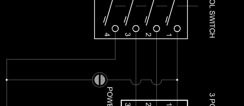
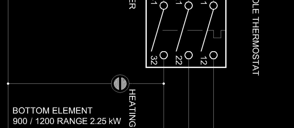

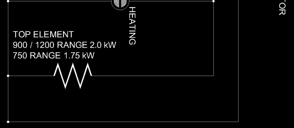
23 Wiring Schematics Wiring Layout for Static Oven Wiring Layout for Convection Oven 21

 can only be adjusted in accordance with the following instructions and shall be re-sealed before re-commissioning this appliance.")


24 Gas Conversion and Specifications Conversion Procedure Caution Ensure Appliance is isolated from gas and electrical supply before commencing servicing. NOTE: Gas conversions should only be carried out by qualified persons. All connections must be checked for leaks before re-commissioning the appliance. Adjustment of components that have adjustments / settings sealed (e.g. paint sealed) can only be adjusted in accordance with the following instructions and shall be re-sealed before re-commissioning this appliance. For all relevant gas specifications, refer to Gas Specifications table at end of this section. Gas Griddle Main Burner Injectors Main Injector 1. Remove the following:- Gas control knobs. Grease Tray Control Panel. Disconnect electrical connection lead from rear of piezo igniters. 2. Remove main burner injectors and replace with correct size injectors as shown in Gas Specifications Tables at rear of this section. 3. Ensure that the aeration sleeve is pushed fully IN into the burner and locked in position with the securing screw. Pilot Burners 1. Carry out the following:- Remove the piezo igniter lead. Unscrew and remove the piezo igniter. Slacken the gas supply tube at gas control end. Disconnect gas supply tube to the pilot burner. Pilot Injector Gas Supply Pipe Thermocouple Piezo Igniter 2. Remove pilot injector and replace with correct size injector as shown in the Gas Specifications Tables at the rear of this section. 3. Reconnect the following:- Gas supply tube to pilot burner. Tighten gas supply tube at gas control end. Refit piezo igniter. Re-connect lead to piezo igniter. Low Fire Adjustment - (Gas Griddle) To change gas griddle thermostat Low Fire adjustment, low fire screw on gas control valve should be screwed fully in, then un-screwed by 1 full turn as shown in Gas Specifications table at end of this section. 1. Screw Low Fire screw fully IN and then unscrew by 1 Full Turn of Low Fire screw. (Refer to Gas Specification table at rear of this section). 2. Ensure Gas Control Pilot Screw is adjusted to 3 turns out c.c.w. 3. Refit control panel 4. Refit gas control knob. Piezo Igniter Pilot Injector Viewed from inside Burner Box Pilot Screw Thermocouple Low Fire Adjust Screw NOTE: Low Fire Screw should be sealed with coloured paint on completion of low fire adjustment. 22
25 Gas Conversion and Specifications Gas Regulator - NAT Gas / LPG / Butane Only. NOTE: Gas regulator supplied is convertible between Natural Gas and LP Gas, but it s outlet pressure is fixed ex-factory and is NOT to be adjusted. NOTE, Pin rotated for Natural Gas. NOTE, Pin rotated for LPG. - Town Gas Only. 1. Remove slotted cap from regulator. 2. Turn On gas supply and appliance. 3. Adjust pressure adjusting screw to achieve correct burner operating pressure. Cap Nut Pressure Adjusting Screw NOTE: Measure burner operating pressure at gas valve outlet test point with burner operating at 'High Flame' setting. 4. Verify operating pressure remains correct (Re-adjust regulator if required). 5. Screw cap nut back onto regulator. Gas Type Labels On completion of the gas conversion, replace the gas type labels located at:- - Rear of the appliance, above the gas connection point. - Beside the rating plate. Commissioning Before leaving installation; 1. Check all gas connections for leaking using soapy water or other gas detecting equipment. Warning DO NOT USE A NAKED FLAME TO CHECK FOR GAS LEAKAGES. 2. Carry out a Commissioning check of the appliance as shown in the Installation Section of this manual. 3. Ensure that any adjustments done to components that have adjustments / settings that are paint sealed, these are to be re-sealed. NOTE: If for some reason it is not possible to get the appliance to operate correctly, shut Off the gas and power supply and contact supplier of this appliance. 23
 Burner Operating Pressure (*) 0.")
26 Gas Conversion and Specifications Gas Specifications - Australia: Natural Gas LP Gas (Propane) GPE506/GPE56 GPE508/GPE58 GPE506/GPE56 GPE508/GPE58 Main Burner 3.00mm 2.85mm 1.80mm 1.70mm Pilot Burner Low Fire Adjustment High Fire Adjustment 1 full turn counter clockwise from the Fully IN position Maximum Flow Screw. Fully IN (Note 1) Burner Operating Pressure (*) 0.90 kpa (Note 2) 2.6 kpa (Note 2) Gas Regulator Cap Screw - New Zealand: Natural Gas LP Gas GPE506/GPE56 GPE508/GPE58 GPE506/GPE56 GPE508/GPE58 Main Burner 3.00mm 2.85mm 1.80mm 1.70mm Pilot Burner Low Fire Adjustment High Fire Adjustment 1 full turn counter clockwise from the Fully IN position Maximum Flow Screw. Fully IN (Note 1) Burner Operating Pressure (*) 0.90 kpa (Note 2) 2.6 kpa (Note 2) Gas Regulator Cap Screw - UK Only: Category: II 2H3P. Flue Type: A 1. Natural Gas (G20) Propane (G31) GPE506/GPE56 GPE508/GPE58 GPE506/GPE56 GPE508/GPE58 Main Burner Injector 3.00mm 2.85mm 1.80mm 1.70mm Pilot Burner Injector Low Fire Adjustment 1 Full Turn Counter Clockwise from the 'Fully In' Position High Fire Adjustment Maximum Flow Screw. Fully In c.w. (Note 1) Burner Operating Pressure (*) 8.2 mbar (Note 2) 26 mbar (Note 2) Supply Pressure 20 mbar 37 mbar Gas Regulator Cap Screw Note 1 Gas Control Valve is fitted with a maximum flow bypass blanking screw, non adjustable. Note 2 Measure burner operating pressure at griddle gas control valve outlet test point with one griddle burner operating at full setting. Operating pressure is ex-factory set, through appliance regulator and is not to be adjusted, apart from when carrying out gas conversion, if required. (Refer to Gas Conversion section for details). 24
27 Gas Conversion and Specifications - All Other Markets: Natural Gas LPG Butane Town Gas Main Burner GP8910GE / GEC 3.00mm 1.80mm 1.65mm 5.50mm GP8121GE / GEC 2.85mm 1.70mm 1.55mm 5.20mm Pilot Injector Low Fire Adjustment 1 Full Turn Counter Clockwise from the 'Fully In' Position. High Fire Adjustment Maximum Flow Screw. Fully In c.w. Burner Operating Pressure (*) 0.90 kpa 2.6 kpa 0.63 kpa Supply Pressure kpa kpa kpa Gas Regulator Cap Screw Adjustable Regulator (Adjust to Burner Operating Pressure specified) NOTE: Measure burner operating pressure at manifold test point with two burners operating at 'High Flame' setting. NAT, LPG & Butane Only - Operating pressure is ex-factory set and is not to be adjusted, apart from when converting between gasses, if required. TOWN GAS Only - Burner operating pressure is to be adjusted using Town Gas adjustable gas regulator supplied. Refer to Gas Conversion and Specifications section of this manual for further details. 25
28 Replacement Parts List Replacement Parts List IMPORTANT: Only genuine authorized replacement parts should be used for servicing and repair of this appliance. Instructions supplied with the parts should be followed when replacing components. For further information and servicing instructions, contact your nearest authorized service branch (contact details are as shown on reverse of front cover of this manual). When ordering replacement parts, please quote the part number and the description as listed below. If the part required is not listed below, request the part by description and quote model number and serial number which is shown on the rating plate. Griddle Oven Burner Pilot Burner Kit Piezo Igniter Piezo Housing Piezo HT Lead 250mm Eurosit Gas Thermostat Knob Adaptor Eurosit Gas Control Knob - 100ºC to 290ºC Overtemp 365 Millivolt Thermocouple Interruped - Leaded (If Overtemp Fitted) Thermocouple (If no Overtemp Fitted) Main Injector (Nat Gas) 3.00mm (GP8910GE / GEC) Main Injector (Nat Gas) 2.85mm (GP8121GE / GEC) Main Injector (LPG) 1.80mm (GP8910GE / GEC) Main Injector (LPG) 1.70mm (GP8121GE / GEC) Main Injector (Butane) 1.65mm (GP8910GE / GEC) Main Injector (Butane) 1.55mm (GP8121GE / GEC) Main Injector (Town Gas) 5.50mm (GP8910GE / GEC) Main Injector (Town Gas) 5.20mm (GP8121GE / GEC) Pilot Injector (Nat Gas) Pilot Injector (LPG / Butane) Pilot Injector (Town Gas) Oven Top Element 2kW Oven Bottom Element 4.5kW Indicator Neon (Amber) Indicator Neon (White) Thermostat C Switch (4-pole) Control Knob Thermostat C Door Spring Kit Terminal Block Mains Energy Regulator. (Static Ovens Only) Control Knob HI/LO. Convection Oven Only Oven Door Microswitch Motor Capacitor 4µf Fan. (Convection Ovens Only) Motor. (Convection Ovens Only). 26
29 Replacement Parts List General Oven Side Rack LH Oven Side Rack RH Oven Rack Grease Drawer Leg 150mm (Adjustable) Rear Roller Assy. Griddle Plate Options Griddle Plate Standard Chromed-(C) Ribbed & Chromed Options 900mm PGH920 PGH920C ON REQUEST (depending on ribbed section 1200mm PGH1220 PGH1220C width on LH or RH side). Accessories Griddle Scraper Tool Smooth Plate Scraper Blades (Pack of 5 blades) Ribbed Plate Scraper Blade (Individual Blade) mm Plinth Kit (900mm Range) mm Plinth Kit (1200mm Range). Gas Regulators Gas Type Part No. Gas Regulators Description Nat. Gas LPG ¾ BSP F/F Convertible. Butane Town Gas ¾ BSP F/F Adjustable. Gas Conversion Kits Models Gas Type to Convert to: Nat. Gas LPG Butane Town Gas Nat. Gas (UK) LPG (UK) GPE506 / GPE508 /
30
INSTALLATION AND OPERATION MANUAL ELECTRIC GRIDDLE EP514 EP516 EP518. For use in GB & IE
 INSTALLATION AND OPERATION MANUAL ELECTRIC GRIDDLE EP5 EP56 EP58 For use in GB & IE 35- MANUFACTURED BY Moffat Limited Rolleston 65 New Zealand INTERNATIONAL CONTACTS AUSTRALIA Moffat Pty Limited Web:
Electric Griddle GPL8600E GPL8900E GPL8120E GP8600E GP8900E GP8120E. Installation and Operation Manual. For use in GB & IE
 Installation and Operation Manual Electric Griddle GP8600E GP800E GP80E GPL8600E GPL800E GPL80E Date Purchased Serial Number Dealer Service Provider For use in GB & IE 350-3 MANUFACTURED BY Moffat Limited
GAS GRIDDLE GP514 GP516 GP518
 INSTALLATION AND OPERATION MANUAL GAS GRIDDLE GP514 GP516 GP518 232422-10 MANUFACTURED BY Moffat Limited Christchurch New Zealand INTERNATIONAL CONTACTS AUSTRALIA Moffat Pty Limited Web: www.moffat.com.au
GAS GRIDDLE GP513 GP514 GP516 GP518
 INSTALLATION AND OPERATION MANUAL GAS GRIDDLE GP513 GP514 GP516 GP518 For use in GB & IE 229284-18 MANUFACTURED BY Moffat Limited Rolleston 7675 New Zealand INTERNATIONAL CONTACTS AUSTRALIA Moffat Pty
Gas Range Static Oven
 Installation and Operation Manual Gas Range Static Oven Series RN8910G RNL8910G RNB8910G RNLB8910G Date Purchased Serial Number Dealer Service Provider 1 For use in GB & IE 232779-8 MANUFACTURED BY Moffat
Gas Griddle GPL8450G GPL8600G GPL8900G GPL8120G GP8450G GP8600G GP8900G GP8120G. Installation and Operation Manual. 1 For use in GB & IE
 Installation and Operation Manual Gas Griddle GP8450G GP8600G GP8900G GP8120G GPL8450G GPL8600G GPL8900G GPL8120G Date Purchased Serial Number Dealer Service Provider 1 For use in GB & IE 228676-24 MANUFACTURED
GAS RANGE STATIC OVEN
 INSTALLATION AND OPERATION MANUAL GAS RANGE STATIC OVEN G504 G528 For use in GB, IE & DK 230103-15 MANUFACTURED BY Moffat Limited Rolleston 7675 New Zealand INTERNATIONAL CONTACTS AUSTRALIA Moffat Pty
Gas Range Static Oven
 Installation and Operation Manual Gas Range Static Oven Series RN8510G RN8610G RN8810G RNL8510G RNL8610G RNL8810G RNB8510G RNB8610G RNB8810G RNLB8510G RNLB8610G RNLB8810G Date Purchased Serial Number Dealer
Gas Range Electric Static/Convection Ovens
 Installation and Operation Manual Gas Range Electric Static/Convection Ovens RN8910GE RN8910GEC RNL8910GE RNL8910GEC Date Purchased Serial Number Dealer Service Provider For use in GB & IE 232781-8 MANUFACTURED
INSTALLATION AND OPERATION MANUAL GAS GRIDDLE TOASTER G55T. For use in GB & IE
 INSTALLATION AND OPERATION MANUAL GAS GRIDDLE TOASTER G55T For use in GB & IE 228001-7 MANUFACTURED BY Moffat Limited Christchurch New Zealand INTERNATIONAL CONTACTS AUSTRALIA Moffat Pty Limited Web: www.moffat.com.au
INSTALLATION AND OPERATION MANUAL ELECTRIC COOKTOP E512 E514 E516. For use in GB & IE
 INSTALLATION AND OPERATION MANUAL ELECTRIC COOKTOP E512 E514 E516 For use in GB & IE 229356-6 MANUFACTURED BY Moffat Limited Rolleston 7675 New Zealand INTERNATIONAL CONTACTS AUSTRALIA Moffat Pty Limited
Gas Cooktops (450mm Wide Hobs)
") Installation and Operation Manual Gas Cooktops (450mm Wide Hobs) Series RN8450G RNL8450G RNB8450G RNLB8450G RN8900G RNL8900G RNB8900G RNLB8900G Date Purchased Serial Number Dealer Service Provider For
Installation and Operation Manual Gas Cooktops (450mm Wide Hobs) Series RN8450G RNL8450G RNB8450G RNLB8450G RN8900G RNL8900G RNB8900G RNLB8900G Date Purchased Serial Number Dealer Service Provider For
Gas Griddle Toaster. Model CT6 INSTALLATION AND OPERATION MANUAL
 Gas Griddle Toaster Model CT6 INSTALLATION AND OPERATION MANUAL 228009-6 MANUFACTURED BY Moffat Limited Christchurch New Zealand INTERNATIONAL CONTACTS AUSTRALIA Moffat Pty Limited E.Mail: vsales@moffat.com.au
Installation and Operation Manual. Gas Griddle Toaster. Date Purchased. Serial Number. Dealer. Service Provider. For use in GB & IE
 Installation and Operation Manual Gas Griddle Toaster GT8600G GTL8600G GTB8600G GTLB8600G Date Purchased Serial Number Dealer Service Provider For use in GB & IE 228002-16 MANUFACTURED BY Moffat Limited
GAS TARGET TOP / STATIC OVEN RANGE
 INSTALLATION AND OPERATION MANUAL GAS TARGET TOP / STATIC OVEN RANGE G570 232426-8 MANUFACTURED BY Moffat Limited Christchurch New Zealand INTERNATIONAL CONTACTS AUSTRALIA Moffat Pty Limited E.Mail: vsales@moffat.com.au
Gas Target Top Range Static Oven
 Installation and Operation Manual Gas Target Top Range Static Oven RN8110G RNB8110G RNL8110G RNLB8110G Date Purchased Serial Number Dealer Service Provider 1 For use in GB & IE 228682-14 MANUFACTURED BY
Gas Ranges Electric Static/Convection Oven
 Installation and Operation Manual Gas Ranges Electric Static/Convection Oven RN8510GE/GEC RN8610GE/GEC RN8810GE/GEC RNL8510GE/GEC RNL8610GE/GEC RNL8810GE/GEC Date Purchased Serial Number Dealer Service
INSTALLATION AND OPERATION MANUAL GAS CHARGRILL G592 G593 G594 G596 G598. For use in GB, IE & DK
 ` INSTALLATION AND OPERATION MANUAL GAS CHARGRILL G592 G593 G594 G596 G598 For use in GB, IE & DK 228593-24 MANUFACTURED BY Moffat Limited Rolleston 7675 New Zealand INTERNATIONAL CONTACTS AUSTRALIA Moffat
Gas Range Convection Oven
 Installation and Operation Manual Gas Range Convection Oven RN8510GC RN8610GC RN8810GC RNL8510GC RNL8610GC RNL8810GC Date Purchased Serial Number Dealer Service Provider For use in GB, IE & DK 228680-23
Electric Cooktop. Series. Installation and Operation Manual
 Installation and Operation Manual Electric Cooktop Series RN8200E RNL8200E RNB8200E RNLB8200E RN8400E RNL8400E RNB8400E RNLB8400E RN8600E RNL8600E RNB8600E RNLB8600E Date Purchased Serial Number Dealer
Gas Cooktops. Installation and Operation Manual
 Installation and Operation Manual Gas Cooktops Series RN8200G RNL8200G RNB8200G RNLB8200G RN8400G RNL8400G RNB8400G RNLB8400G RN8600G RNL8600G RNB8600G RNLB8600G RN8800G RNL8800G RNB8800G RNLB8800G Date
Gas Cooktops. Models: C6 (600mm) C9 (900mm) INSTALLATION AND OPERATION MANUAL. For use in GB & IE
 C9 (900mm) INSTALLATION AND OPERATION MANUAL. For use in GB & IE") Gas Cooktops Models: C6 (600mm) C9 (900mm) INSTALLATION AND OPERATION MANUAL For use in GB & IE 230635-7 MANUFACTURED BY Moffat Limited Christchurch New Zealand INTERNATIONAL BRANCHES AUSTRALIA Moffat
Gas Cooktops Models: C6 (600mm) C9 (900mm) INSTALLATION AND OPERATION MANUAL For use in GB & IE 230635-7 MANUFACTURED BY Moffat Limited Christchurch New Zealand INTERNATIONAL BRANCHES AUSTRALIA Moffat
GAS TARGET TOP / STATIC OVEN RANGE
 INSTALLATION AND OPERATION MANUAL GAS TARGET TOP / STATIC OVEN RANGE G570 For use in GB & IE 230096-8 MANUFACTURED BY Moffat Limited Christchurch New Zealand INTERNATIONAL CONTACTS AUSTRALIA Moffat Pty
Installation and Operation Manual. Gas Target Top. Date Purchased. Serial Number. Dealer. Service Provider. For use in GB & IE
 Installation and Operation Manual Gas Target Top RN8100G RNL8100G RNB8100G RNLB8100G Date Purchased Serial Number Dealer Service Provider For use in GB & IE 228092-20 MANUFACTURED BY Moffat Limited Rolleston
GAS STATIC OVEN RANGES
 INSTALLATION AND OPERATION MANUAL GAS STATIC OVEN RANGES G504 G528 232428-3 MANUFACTURED BY Moffat Limited Christchurch New Zealand INTERNATIONAL CONTACTS AUSTRALIA Moffat Pty Limited E.Mail: vsales@moffat.com.au
GAS TARGET TOP RANGE/ CONVECTION OVEN
 INSTALLATION AND OPERATION MANUAL GAS TARGET TOP RANGE/ CONVECTION OVEN G576 232427-8 MANUFACTURED BY Moffat Limited Christchurch New Zealand INTERNATIONAL CONTACTS AUSTRALIA Moffat Pty Limited E.Mail:
INSTALLATION AND OPERATION MANUAL GAS SALAMANDER G91 G91B. For use in GB & IE
 om INSTALLATION AND OPERATION MANUAL GAS SALAMANDER G91 G91B For use in GB & IE 231920-11 MANUFACTURED BY Moffat Limited Rolleston 7675 New Zealand INTERNATIONAL CONTACTS AUSTRALIA Moffat Pty Limited Web:
CSP6 - Gas Stock Pot INSTALLATION AND OPERATION MANUAL
 CSP6 - Gas Stock Pot INSTALLATION AND OPERATION MANUAL 240897-1 Moffat Limited Rolleston 7675 New Zealand AUSTRALIA Moffat Pty Limited E.Mail: vsales@moffat.com.au Main Office: (tel): +61 (03) 9518 3888
Installation and Operation Manual. Gas Bratt Pan. Date Purchased. Serial Number. Dealer. Service Provider. For use in GB & IE
 Installation and Operation Manual Gas Bratt Pan BP8080G BP8080GE BP8120G BP8120GE BPL8080G BPL8080GE BPL8120G BPL8120GE Date Purchased Serial Number Dealer Service Provider For use in GB & IE 228688-16
INSTALLATION AND OPERATION MANUAL GAS SALAMANDER G91 G91B. For use in GB & IE
 INSTALLATION AND OPERATION MANUAL GAS SALAMANDER G91 G91B For use in GB & IE 231920-8 MANUFACTURED BY Moffat Limited Christchurch New Zealand INTERNATIONAL CONTACTS AUSTRALIA Moffat Pty Limited Web: www.moffat.com.au
Installation and Operation Manual. Gas Salamander SN8200G SN8200GB. Date Purchased. Serial Number. Dealer. Service Provider
 Installation and Operation Manual Gas Salamander SN8200G SN8200GB Date Purchased Serial Number Dealer Service Provider 232460-6 MANUFACTURED BY Moffat Limited Christchurch New Zealand INTERNATIONAL CONTACTS
Gas Salamander. Model CS9 INSTALLATION AND OPERATION MANUAL. For use in GB & IE
 Gas Salamander Model CS9 INSTALLATION AND OPERATION MANUAL For use in GB & IE 230628-7 MANUFACTURED BY Moffat Limited Christchurch New Zealand INTERNATIONAL CONTACTS AUSTRALIA Moffat Pty Limited Web: www.moffat.com.au
Electric Pasta Cooker
 Installation and Operation Manual Electric Pasta Cooker PC8140E PCB8140E PC8140E-7 PCB8140E-7 PCL8140E PCLB8140E PCL8140E-7 PCLB8140E-7 Date Purchased Serial Number Dealer Service Provider For use in GB
GAS RANGE STATIC OVEN
 INSTALLATION AND OPERATION MANUAL GAS RANGE STATIC OVEN G505 G506 G508 232429-3 MANUFACTURED BY Moffat Limited PO Box 10001 Christchurch New Zealand Ph: (03) 389 1007 Fax: (03) 389 1276 WORLD-WIDE BRANCHES
GAS STATIC OVEN RANGES
 INSTALLATION AND OPERATION MANUAL GAS STATIC OVEN RANGES G504 G528 For use in GB, IE & DK 230103-11 MANUFACTURED BY Moffat Limited PO Box 10001 Christchurch New Zealand Ph: (03) 389 1007 Fax: (03) 389
INSTALLATION AND OPERATION MANUAL GAS COOKTOP. Series G512 G514 G516 G
 INSTALLATION AND OPERATION MANUAL GAS COOKTOP Series G512 G514 G516 G518 232423-5 MANUFACTURED BY Moffat Limited PO Box 10001 Christchurch New Zealand Ph: (03) 389 1007 Fax: (03) 389 1276 WORLD-WIDE BRANCHES
400mm Gas Fryer. Model CF4 INSTALLATION AND OPERATION MANUAL. For use in GB & IE
 400mm Gas Fryer Model CF4 INSTALLATION AND OPERATION MANUAL For use in GB & IE 230114-9 MANUFACTURED BY Moffat Limited Christchurch New Zealand INTERNATIONAL CONTACTS AUSTRALIA Moffat Pty Limited E.Mail:
Induction Cooktop. Installation and Operation Manual IN8200E INL8200E INB8200E INLB8200E IN8400E INL8400E INB8400E INLB8400E. For use in GB & IE
 Installation and Operation Manual Induction Cooktop IN8200E INL8200E INB8200E INLB8200E IN8400E INL8400E INB8400E INLB8400E Date Purchased Serial Number Dealer Service Provider 1 For use in GB & IE 2350343
Thor Gas Griddle Installation and Operation Instructions
 Thor Gas Griddle Installation and Operation Instructions Model:,,, IMPORTANT FOR FUTURE REFERENCE Please complete this information and retain this manual for the life of the equipment. For Warranty Service
400mm Gas Fryer. Model FF18
 400mm Gas Fryer Model FF18 INSTALLATION AND OPERATION MANUAL 236859-6 MANUFACTURED BY Moffat Limited Rolleston 7675 New Zealand INTERNATIONAL CONTACTS AUSTRALIA Moffat Pty Limited E.Mail: vsales@moffat.com.au
Installation and Operation Manual. Gas Pasta Cooker. Date Purchased. Serial Number. Dealer. Service Provider. For use in GB & IE
 Installation and Operation Manual Gas Pasta Cooker PC8140G PCL8140G Date Purchased Serial Number Dealer Service Provider For use in GB & IE 230008-10 MANUFACTURED BY Moffat Limited PO Box 10001 Christchurch
Thor Gas Char-Broiler Installation and Operation Instructions
 Thor Gas Char-Broiler Installation and Operation Instructions Model:,,, IMPORTANT FOR FUTURE REFERENCE Please complete this information and retain this manual for the life of the equipment. For Warranty
INSTALLATION AND OPERATION MANUAL 'VEE-RAY' GAS FRYERS GT60HPO
 INSTALLATION AND OPERATION MANUAL 'VEE-RAY' GAS FRYERS GT60HPO 229280-13 MANUFACTURED BY Moffat Limited Rolleston 7675 New Zealand INTERNATIONAL CONTACTS AUSTRALIA Moffat Pty Limited E.Mail: vsales@moffat.com.au
30DSERIES E32D4. (Digital Operation) Installation and Operation Manual
 Installation and Operation Manual") 30DSERIES E32D4 (Digital Operation) Installation and Operation Manual 234781-12 MANUFACTURED BY Moffat Limited Christchurch New Zealand INTERNATIONAL CONTACTS AUSTRALIA Moffat Pty Limited Web: www.moffat.com.au
30DSERIES E32D4 (Digital Operation) Installation and Operation Manual 234781-12 MANUFACTURED BY Moffat Limited Christchurch New Zealand INTERNATIONAL CONTACTS AUSTRALIA Moffat Pty Limited Web: www.moffat.com.au
GAS GRIDDLE INSTRUCTIONS MODEL: PGG6 MODEL: PGG7
 Page 1 of 17 GAS GRIDDLE INSTRUCTIONS MODEL: PGG6 MODEL: PGG7 SAFETY INSTRUCTIONS INSTALLATION INSTRUCTIONS OPERATION INSTRUCTIONS MAINTENANCE INSTRUCTIONS CONVERSION INSTRUCTIONS TECHNICAL DATA PARTS
Thor Gas Fryer Installation and Operation Instructions
 Thor Gas Fryer Installation and Operation Instructions Model: GL165-P, GL165-N, GL166-P, GL166-N IMPORTANT FOR FUTURE REFERENCE Please complete this information and retain this manual for the life of the
STAR-MAX PROPANE GAS GRIDDLE
 Star Manufacturing International Inc. 10 Sunnen Drive St. Louis, MO 63143 Phone: (314) 781-2777 Fax: (314) 781-3636 Installation and Operating Instructions 2M-Z3793 Rev. B 3/28/03 STAR-MAX PROPANE GAS
User, Installation and Servicing Instructions. Silverlink 600 Gas Griddles GS4 and GS7 IS212 ECN3592
 User, Installation and Servicing Instructions Silverlink 600 Gas Griddles GS4 and GS7 IS212 ECN3592 INSTALLATION AND SERVICING INSTRUCTIONS Please read the following carefully before commencing work on
Installation, Operating and Servicing Instructions
 Installation, Operating and Servicing Instructions Opus 800 Gas Boiling Tops OG8003, OG8004 & OG8009 Please make a note of your product details for future use: Date Purchased: Model Number: Serial Number:
STAR-MAX GAS GRIDDLES MODELS 615MA 624MA 636MA 648MA 615TA 624TA 636TA 648TA 624TSPA 636TSPA 648TSPA
 Star Manufacturing International Inc. 10 Sunnen Drive St. Louis, MO 63143 Phone: (314) 781-2777 Fax: (314) 781-3636 Installation and Operating Instructions 2M-Z1351 Rev. B 4/23/04 STAR-MAX GAS GRIDDLES
Belling. Gas Hob GHU573 - GHU573T GHU70GE - GHU70TGE - GHU70GC GHU70TGC - GHU60GC INSTALLATION AND USER INSTRUCTIONS
 Belling Gas Hob GHU573 - GHU573T GHU70GE - GHU70TGE - GHU70GC GHU70TGC - GHU60GC INSTALLATION AND USER INSTRUCTIONS Note: This appliance is supplied for use with Natural Gas and can be converted to LPG
User, Installation and Servicing Instructions. Opus 700 Gas Griddle OG7201, OG7202, OG7203, OG7204, OG7207, OG7208 IS349 ECN3592
 User, Installation and Servicing Instructions Opus 700 Gas Griddle OG7201, OG7202, OG7203, OG7204, OG7207, OG7208 IS349 ECN3592 Dear Customer, Thank you for purchasing this Lincat product. This is just
HOW TO USE YOUR 2500 RANGE L.P.G. COOKER OR HOB UNIT
 HOW TO USE YOUR 2500 RANGE L.P.G. COOKER OR HOB UNIT CAUTION These instructions must be read and understood before proceeding with the installation and to avoid any possibility of accident it is essential
USHO COOKER INSTALLATION INSTRUCTIONS SAFETY INSTRUCTIONS USER INSTRUCTIONS MODEL: USHO. INSTRUCTION REF: IN152 ISSUE No. 4 DATE
 Page 1 of 11 INSTALLATION INSTRUCTIONS SAFETY INSTRUCTIONS USER INSTRUCTIONS USHO COOKER MODEL: USHO Page 2 of 11 WARNING To avoid scratching the highly polished exterior surface of this equipment whilst
VULCAN GAS RANGES RG-6 OPEN BURNER
 VULCAN GAS RANGES RG-6 OPEN BURNER Index: General data 2 Owner s Responsibility 3 authorised Vulcan catering Equipment Branches and dealers 3 Parts Ordering / Service Information 4 Prior to Installation
HOW TO USE YOUR 2000 RANGE L.P.G. COOKER OR HOB UNIT
 HOW TO USE YOUR 2000 RANGE L.P.G. COOKER OR HOB UNIT CAUTION These instructions must be read and understood before proceeding with the installation and to avoid any possibility of accident it is essential
GAS GRIDDLE INSTRUCTIONS MODEL: PGF GRIDDLES PGF 300, 600, 800, 1200
 Page 1 of 17 GAS GRIDDLE INSTRUCTIONS MODEL: PGF GRIDDLES PGF 300, 600, 800, 1200 VALIDATE WARRANTY SAFETY INSTRUCTIONS INSTALLATION INSTRUCTIONS OPERATION INSTRUCTIONS MAINTENANCE INSTRUCTIONS CONVERSION
Patio Heater Model No. GM and GM
 Patio Heater Model No. GM124-003 and GM124-004 FEATURES: The ideal solution for extending the season for outdoor entertaining Maximum output 39.6 MJ/hr Direct ignition Adjustable heat output Safety tip-over
Electric Deep Fryer FNL8127E/EE FNL8224E/EE. Installation and Operation Manual. For use in GB & IE Date Purchased. Serial Number.
 Installation and Operation Manual Electric Deep Fryer FNL8127E/EE FNL8224E/EE Date Purchased Serial Number Dealer Service Provider For use in GB & IE 236002-2 MANUFACTURED BY Moffat Limited Christchurch
OG7302 Salamander Grill
 OG7302 Salamander Grill USER, INSTALLATION, SERVICING AND CONVERSION INSTRUCTIONS For use in GB & IE IS370 ECN3280 1 Dear Customer, Thank you for purchasing this Lincat product. This is just one of over
Thor Gas Hob Installation and Operation Instructions
 Thor Gas Hob Installation and Operation Instructions 0359-15 PIN: 0359CN1290 BS EN203-1:2014 Gas heated catering equipment (TYPE A) Model: GL169-P, GL169-N IMPORTANT FOR FUTURE REFERENCE Please complete
Thor Gas Hot Plate Technical Service Manual
 Thor Gas Hot Plate Technical Service Manual Model: GH107-P, GH107-N IMPORTANT FOR FUTURE REFERENCE Please complete this information and retain this manual for the life of the equipment. For Warranty Service
GAS GRIDDLE INSTRUCTIONS MODEL: PGF GRIDDLES GGP6.4, 6.6, 6.8, 6.10
 Page 1 of 18 GAS GRIDDLE INSTRUCTIONS MODEL: PGF GRIDDLES GGP6.4, 6.6, 6.8, 6.10 VALIDATE WARRANTY SAFETY INSTRUCTIONS INSTALLATION INSTRUCTIONS OPERATION INSTRUCTIONS MAINTENANCE INSTRUCTIONS CONVERSION
2 BURNER LP GAS STOVE OPERATING INSTRUCTIONS
 BURNER LP GAS STOVE OPERATING INSTRUCTIONS Part No. 5090 IMPORTANT Read these instructions for use carefully. Familiarise yourself with the appliance before connecting it to it s gas container. Keep these
Glen Dimplex Professional Appliances: Salamander Grill (GB/IE)
") Glen Dimplex Professional Appliances: Salamander Grill (GB/IE) This appliance must be installed by a competent person in compliance with the installation and servicing instructions and national regulations
Glen Dimplex Professional Appliances: Salamander Grill (GB/IE) This appliance must be installed by a competent person in compliance with the installation and servicing instructions and national regulations
Wok Cookers Instruction Manual
 Wok Cookers Instruction Manual Part No. DC100-09 Single Burner Wok Cooker Part No. DC200-09 Double Burner Wok Cooker IMPORTANT It is IMPORTANT that you read these instructions carefully and understand
GAS COOKER GAS OVEN SERIES. Owner s Manual Please read this manual carefully before operating your set. Retain it for future reference.
 GAS COOKER GAS OVEN SERIES Owner s Manual Please read this manual carefully before operating your set. Retain it for future reference. Record model number and serial number of the set. See the label attached
Proline GAS HOB Model TCG40IX Instruction Book
 Proline GAS HOB Model TCG40IX Instruction Book GB Operating and Installation Instructions Index Technical data and specifications...... 3 Installation...................... 3-6 Ventilation........................
Installation, Operating and Servicing Instructions
 Installation, Operating and Servicing Instructions Opus 800 Electric Oven Ranges OE8015 Please make a note of your product details for future use: Date Purchased: Model Number: Serial Number: Dealer: IS
THE INSTRUCTIONS IN THIS MANUAL APPLY TO KENT GAS FIRES. CONTENTS:-
 THE INSTRUCTIONS IN THIS MANUAL APPLY TO KENT GAS FIRES. THE MODELS COVERED ARE:- For use with Natural Gas:- KENT ESTATE NG, KENT ULTIMA NG For use with Liquid Propane Gas (LPG):- KENT ESTATE LP, KENT
HOW TO USE YOUR 4500 RANGE L.P.G. COOKER OR HOB UNIT
 HOW TO USE YOUR 4500 RANGE L.P.G. COOKER OR HOB UNIT If the appliance does not operate correctly contact your supplier Or Leisure Products (Bolton) Ltd Holly Street, Bolton, BL1 8QR. England. ~~~~ For
User, Installation, Servicing and Conversion Instructions. Opus 700 Gas Oven Ranges OG7001 & OG7002 IS431 ECN3592
 User, Installation, Servicing and Conversion Instructions Opus 700 Gas Oven Ranges OG7001 & OG7002 IS431 ECN3592 Dear Customer, Thank you for purchasing this Lincat product. This is just one of over 450
TURBOFAN E25T. Equipment Operation Manual. McDonald s. Moffat Pty Limited 740 Springvale Rd Mulgrave, VIC, 3170, AUSTRALIA
 TURBOFAN E25T Equipment Operation Manual This equipment chapter is to be inserted in the appropriate section of the Equipment Manual. Manufactured exclusively for McDonald s By Moffat Pty Limited 740 Springvale
Rambo CAST IRON RING BURNERS OPERATING INSTRUCTIONS. C40LP 3 Ring Burner C50LP 4 Ring Burner
 Rambo CAST IRON RING BURNERS OPERATING INSTRUCTIONS C20LP 1 Ring Burner C30LP 2 Ring Burner C40LP 3 Ring Burner C50LP 4 Ring Burner IMPORTANT: READ THESE INSTRUCTIONS FOR USE CAREFULLY. KEEP THESE INSTRUCTIONS
PARAGON GAS FRYER INSTALLATION INSTRUCTIONS SAFETY INSTRUCTIONS USER INSTRUCTIONS MODEL : PDGF/PDGFP
 Page 1 of 13 INSTALLATION INSTRUCTIONS SAFETY INSTRUCTIONS USER INSTRUCTIONS PARAGON GAS FRYER MODEL : PDGF/PDGFP Page 2 of 13 IMPORTANT PLEASE READ INSTRUCTIONS FULLY BEFORE USE MODEL PDGF FRYER & PDGFP
Outdoor Tabletop Heater TTH20 Series
 Outdoor Tabletop Heater TTH20 Series FEATURES: The ideal solution for extending the outdoor entertaining season Creates a stylish and attractive ambience Casts an approximate 1 to 1.5 metre circle of radiant
Installation, Operating and Servicing Instructions
 Installation, Operating and Servicing Instructions Opus 700 Electric Oven Ranges OE7008, OE7010 Please make a note of your product details for future use: Date Purchased: Model Number: Serial Number: Dealer:
UBGHFF60W 60cm Gas on Glass Gas Hob
 UBGHFF60W 60cm Gas on Glass Gas Hob GB [02] x 1 [03] x 2 [04] x 1 [01] x 1 [08] x 4 [05] x 2 [09] x 1 [06] x 1 [07] x 4 [10] x 4 [11] x 1 TEMPLATE TEMPLATE UBGHFF60W GB Built-in 60cm Gas on Glass Gas Hob
USER MANUAL Gas Countertop Charbroilers
 Gas Countertop Charbroilers REVISED 2/209 382799 LAVA BRIQUETTE MODELS: 35CLCPG5NL, 35CLCPG24NL, 35CLCPG36NL, 35CLCPG48NL, 35CLCPG60NL, 35CLCPG72NL Congratulations on your purchase of Cooking Performance
USERS, INSTALLATION AND SERVICING INSTRUCTIONS
 USERS, INSTALLATION AND SERVICING INSTRUCTIONS GAS BRATT PAN G3800 and G3800DX DATE PURCHASED: MODEL NUMBER: SERIAL NUMBER: DEALER: SERVICE PROVIDER: T100753 Rev. 3 Published: 04 /10/2012 Dear Customer,
F900 SERIES GAS CHARGRILL G9440, G9460, G9490, G User, installation and servicing instructions T Read these instructions before use
 F900 SERIES User, installation and servicing instructions GAS CHARGRILL G9440, G9460, G9490, G94120 Read these instructions before use DATE PURCHASED: MODEL NUMBER: SERIAL NUMBER: DEALER: SERVICE PROVIDER:
INSTALLATION & OPERATION MANUAL
 INSTALLATION & OPERATION MANUAL EF SERIES ECONOFRY GAS FRYERS MODEL EF3 EF4 EF5 ML-52099 ML-114943 ML-114944 MODEL EF3 For additional information on Vulcan-Hart or to locate an authorized parts and service
Manual P/N M0MG32MS. Revision 6/F3587 February, 2005
 G3MS CONVECTION OVEN SERVICE MANUAL Revision 6/F3587 February, 005 Manual P/N M0MG3MS WARNING: ALL INSTALLATION AND SERVICE REPAIR WORK MUST BE CARRIED OUT BY QUALIFIED PERSONS ONLY. -- CONTENTS This manual
Owner s Guide Installation & Operation
 Owner s Guide Installation & Operation Hot Top HHT Series Hestan Commercial Corporation 3375 E. La Palma Ave Anaheim, CA 92806 (888) 905-7463 RETAIN THIS MANUAL FOR FUTURE REFERENCE P/N 002130 REV 1 IMPORTANT
SAFETY PRECAUTIONS 1 11/09 EOPI 33643
 Use and Care of your new AGA Gas Fired Range Models: GC Open Flue Range (2 Oven) GC Direct Vent Range (2 Oven) GE Open Flue Range (4 Oven) GE Direct Vent Range (4 Oven) For U.S. and Canadian Markets NOTE:
BESTLINK INTERNATIONAL. User instructions Maintenance instructions Installation & service instructions
 GMK 10023 AS 4551 BESTLINK INTERNATIONAL User instructions Maintenance instructions Installation & service instructions Cooktop models: BLGSW905CF BLGSW905C BLGSW705CF BLGSW705C BLGSW704CF BLGSW704C BLGSW60CF
Gas Fire Patio Heater Lhotse-817
 Gas Fire Patio Heater Lhotse-817 Instruction Manual Please read the manual BEFORE you unpack or install the fire TABLE OF CONTENTS Warning 3 Getting Started 4 What s Included 5 Assembly Procedures 6 Product
Pizza Oven with Stand
 Pizza Oven with Stand Cooks up to 3 pizzas at a time Use to cook a variety of food Easy clean vitreous enamel interior Model No. P0104 Powerful 22MJ/h stainless steel burner Viewing window and temperature
GARLAND GAS CHARGRILL OWNER S MANUAL. Country of Destination GB and IE. Manual Part No: Gas Chargrill - 1 Manual Rev No: 1
 GARLAND GAS CHARGRILL OWNER S MANUAL Country of Destination GB and IE Manual Part No: 932067-08 Gas Chargrill - 1 IMPORTANT CUSTOMER INFORMATION Please check that the gas taps will press and release freely
PLATE DISPENSER MODEL NUMBERS MPN10000 MPN10500 MPN20000 MPN20500
 V PLATE DISPENSER MODEL NUMBERS MPN10000 MPN10500 MPN20000 MPN20500 Thank you for buying a Victor Unit. We hope and expect that you will get many years of satisfactory use from your purchase. In order
Gas Fire Patio Heater Q9
 Gas Fire Patio Heater Q9 Instruction Manual Please read the manual BEFORE you unpack or install the fire TABLE OF CONTENTS Warning 3 Getting Started 4 What s Included 5 Assembly Procedures 6 Product Drawing
Electric Deep Fryer FN8127E FN8127EE FN8127E21 FN8127EE21 FN8224E FN8224EE FNL8127E FNL8127EE FNL8127E21 FNL8127EE21 FNL8224E FNL8224EE
 Installation and Operation Manual Electric Deep Fryer FN8127E FN8127EE FN8127E21 FN8127EE21 FN8224E FN8224EE FNL8127E FNL8127EE FNL8127E21 FNL8127EE21 FNL8224E FNL8224EE Date Purchased Serial Number Dealer
MEDIUM DUTY ELECTRIC FRYER OWNER S MANUAL. Click here for. Parts List. Manual Part No: MD Electric Fryer - 1 Manual Rev No: 1
 MEDIUM DUTY ELECTRIC FRYER OWNER S MANUAL Click here for Parts List Manual Part No: 930155-01 MD Electric Fryer - 1 Model No. Product Description Rev. Date Electric Fryers MLE30F-F 300 Fryer 2 09/03/00
Thor Gas Oven Installation and Operation Instructions
 Thor Gas Oven Installation and Operation Instructions Model: GH100-P, GH100-N, GH101-P, GH101-N, GH102-P, GH102-N, GE542-P, GE542-N, GE543-P, GE543-N, GE544-P, GE544-N IMPORTANT FOR FUTURE REFERENCE Please
E603 E604 ELECTRIC FRYERS
 E603 E604 ELECTRIC FRYERS 16191-20 MANUFACTURED BY Moffat Limited Christchurch New Zealand INTERNATIONAL CONTACTS AUSTRALIA Moffat Pty Limited E.Mail: vsales@moffat.com.au Main Office: (tel): +61 (03)
User Instruction Manual
 User Instruction Manual Counter Top Convection Oven Please read and keep these instructions These instructions cover the Burco counter top convection oven model CTCO01, SKU 444440542 CTCO01 SKU 444440542
OE7008 & OE7010 Electric Oven Ranges
 OE7008 & OE700 Electric Oven Ranges USER, INSTALLATION AND SERVICING INSTRUCTIONS For use in G & IE IS97 ECN9 Dear Customer, Thank you for purchasing this Lincat product. This is just one of over 00 different
OWNERS MANUAL ELECTRIC STOVES
 OWNERS MANUAL ELECTRIC STOVES Electrolux Home Products 1. READ these instructions carefully before installing and operating the oven. Keep them for further reference. 2. Record in the space below the MODEL
Owner s Guide Installation & Operation
 Owner s Guide Installation & Operation Char Broiler HCH Series Hestan Commercial Corporation 3375 E. La Palma Ave Anaheim, CA 92806 (888) 905-7463 RETAIN THIS MANUAL FOR FUTURE REFERENCE P/N 002134 REV
GARLAND GAS STEAK GRILL OWNER S MANUAL. Click here for Part List. Country of Destination GB and IE
 GARLAND GAS STEAK GRILL OWNER S MANUAL Click here for Part List Country of Destination GB and IE Manual Part No: 932067-06 Gas Steak Grill - 1 IMPORTANT CUSTOMER INFORMATION Please check the gas tap will