Technical Handbook for the Paddy Rice Postharvest lndustry in Developing Countries James E. Wimberly
|
|
|
- Eric Wheeler
- 6 years ago
- Views:
Transcription
1
2
3 Technical Handbook for the Paddy Rice Postharvest lndustry in Developing Countries James E. Wimberly 1983 INTERNATIONAL RICE RESEARCH INSTITUTE LOS BAÑOS, LAGUNA, PHILIPPINES P.O. BOX 933, MANILA, PHILIPPINES
4 The International Rice Research Institute (IRRI) is one of 13 nonprofit international research and training centers supported by the Consultative Group for International Agricultural Research (CGIAR). The CGIAR is sponsored by the Food and Agriculture Organization (FAO) of the United Nations, the International Bank for Reconstruction and Development (World Bank), and the United Nations Development Programme (UNDP). About 50 countries, international and regional organizations, and private foundations comprise the CGIAR. IRRI receives support, through the CGIAR, from a number of donors including: the Asian Development Rank the European Economic Community the Ford Foundation the International Fund for Agricultural Development the OPEC Special Fund the Rockefeller Foundation the United Nations Development Programme and the international aid agencies of thc following governments: Australia Belgium Brazil Canada Denmark Fed. Rep. Germany India Japan Mexico Netherlands New Zealand Philippines Spain Sweden Switzerland United Kingdom United States The responsibility for this publication rests with the International Rice Research Institute. ISBN
5 Contents FOREWORD vii ACKNOWLEDGMENTS INTRODUCTION xi ix Chapter 1/ CLEANING 1 Vibrating sieves 2 Rotating sieves 5 Screens 6 Aspirators 8 Magnetic separators 11 De-stoners 12 Feeding and collecting 15 Capacities 17 Capacities vs size 17 Capacity of paddy vs other grains 17 Capacity vs screen size 17 Chapter 2/ DRYING 19 Drying methods and selection 20 Batch-in-bin dryers 22 Small capacity 22 Large capacity 24 Recirculating batch dryers 28 Continuous-flow dryers 29 Nonmixing types 30 Mixing types 31 Drying systems with tempering 34 Blowers 36 Air heaters 40 Oil fueled 40 Solid fueled 42 Chapter 3/ CONVEYING 45 Bucket elevators 45 General description 45 Types 47
6 Bucket types and capacities 47 Elevator capacities 47 Elevator head section 50 Elevator boot section 51 Elevator legs 52 Belts for bucket elevator 52 Accessories 54 Power requirements 55 Screw conveyors 56 General information 56 Sizes and capacities 57 Hangers and end bearings 60 Inlets and discharge openings 60 Troughs and covers 61 Drive arrangements 62 Portable and bin augers 63 Belt conveyors 65 Other paddy conveyors 73 Shaker conveyor 74 Chain conveyor 74 Pneumatic conveyor 75 Portable conveyor 76 Grain valves and spouting 76 Chapter 4/STORAGE 81 Conditions for safe storage 82 Condition before storage 82 Control of rodents and birds 82 Control of insects 83 Control of microorganisms 83 Relative humidity-moisture content equilibrium 84 Storage facilities 84 Bag storage 86 Bulk storage 90 Chapter 5/PARBOILING 101 Advantages and disadvantages 102 Principles of parboiling 103 Soaking 103 Steaming 103 Drying 104 Methods of parboiling 105 Concrete soaking tanks and steam kettles 105 Goviya plants 107 Large metal tanks used for soaking and steaming 109 Parboiling and drying operations 111 Factors that affect parboiled paddy 113 Cost data 114
7 Chapter 6/MILLING 117 Single-machine mills 117 Multiple-machine mills 119 Cleaning 123 Dehusking equipment 124 Husk separation 127 Paddy separation 129 Compartment-type separator 130 Tray separator 131 Bran removal 133 Vertical abrasive whitener 133 Horizontal abrasive whitener 135 Horizontal friction whitener 137 Rice polishers 138 Grading 139 Rice mill flow diagram, equipment layout and elevation 140 Economics of operation 143 Raw paddy 144 Parboiled paddy 144 Chapter 7/TESTING EQUIPMENT 145 Sampling 145 Moisture measurement 147 Dryer 150 Dockage tester 150 Dehusker 151 Whiteners 154 Graders 155 Grain inspection 158 Laboratory layout 158 Chapter 8/SYSTEMS 161 Economics of the systems approach 162 Systems design 163 Identifying needs 163 Developing a block diagram 164 Developing a flow diagram 164 Developing a plant layout and elevation 165 Investment and operating costs 166 GLOSSARY 169 APPENDICES 172 Appendix 1. Standard screen perforation sizes used in cleaners 172 Appendix 2. Pressure drop through various grain depths 173 Appendix 3. Pressure drop for different grain depths at 4 air flow rates 174 Appendix 4. Chart for estimating weight loss when drying paddy 174
8 Appendix 5. Temperature conversions 175 Appendix 6. Physical characteristics of paddy 175 Appendix 7. Conversion data for drying 176 Appendix 8. Approximate net heating values of various fuels 176 Appendix 9. General conversion data 177
9 Foreword Increases in rice production during the past 20 years have helped many developing countries keep food production above the rate of population growth. But second generation losses those associated with postharvest drying, processing, and storage may amount to about 7% of total rice production, and may reach as high as 26%. A number of international aid agencies as well as the developing countries themselves have mounted programs to reduce postharvest losses. Although there is a distinct need for continuing research and development in the postharvest industry, there exists a wealth of known technology that, if applied now, could contribute substantially to reducing postharvest losses. James Wimberly has compiled the fragmented information that exists and combined it with his own experiences into a clear, comprehensive, and cohesive work that explains: handling, transport, drying, cleaning, storage, parboiling, and milling. For each of the postharvest steps, Wimberly discusses not only appropriate equipment, but performance and design criteria as well. This is not meant to be an engineering textbook. Rather, it spells out for design engineers, manufacturers, construction personnel, and technicians the engineering principles to consider in the design and operation of a paddy processing facility. The performance criteria will enable designers and operators to specify the right equipment based on the volumes of paddy they expect to handle. A particular strength of this book is that it is written for developing countries. Recognizing that highly sophisticated, automated plants are uncommon in developing countries, and may even be undesirable because of their high energy consumption, the author limits his examples and design criteria to situations most likely to be encountered. But the sound engineering principles he enunciates remain the same. The designer in developing countries will especially appreciate the author s evalualion of various equipment for postharvest paddy processing, and his lucid discussion of alternative methods of meeting specific needs. All the alternatives discussed have been proved in practice.
10 The ultimate test of this book will be the contribution it makes to stimulate action to reduce postharvest losses. By adhering to the principles the author presents, those engaged in the postharvest industry can help to ensure that more of production reaches the consumer without deterioration in quality. This volume was edited by W. H. Smith, editor, and Ms. Gloria S. Argosino, assistant editor. M. S. Swaminathan Director General
11 Introduction In the past 25 years, most rice-producing countries of the developing world have had active programs geared to increasing rice production to meet the demands of their growing populations. Emphasis on improving production practices has resulted in an increase in world production from 252 million tons in 1961 to 321 million tons in But the problems associated with paddy production are followed by what are often termed second-generation problems those associated with postharvest. (The term paddy refers to unhulled or rough rice. It is used throughout this book because it is the most common in the major rice-producing countries.) Many international organizations, including the Food and Agriculture Organization (FAO) of the United Nations, the Agricultural Productivity Organization (APO), the International Rice Research Institute (IRRI), and India s Rice Processing Engineering Center (RPEC), have published studies indicating the magnitude of losses in the industry. From these reports losses can be summarized: 2-7% for handling and transport, 1-5% for drying and cleaning, 2-6% for storage, and 2-8% for parboiling and milling, for total losses ranging from 7 to 26%. Thus, if the minimum loss of 7% could be reduced to only 2%, then 5% of the world s rice crop or 15 million tons annually could be saved. Bringing this down to country level, consider Bangladesh, which produces 20 million tons of paddy annually. A 5% saving would add one million tons annually, which at 1979 prices would be worth more than $300 million. This is one example that illustrates the magnitude of postharvest industry problems. Much has been done in the past few years. Beginning with a number of small projects sponsored by FAO, the Ford Foundation, and a number of aid agencies in several countries, the paddy-producing countries of the developing world have begun focusing on these problems and learning how to solve them. What can be done? Continued research and development are needed in the postharvest industry. The known and proven technology must be spread to the users. Even with the publications presently available, there is a substantial gap between known technology and what is available to potential users. Limited engineering data related to design, manufacture, installation, and operation of equipment are available to the user. There is a great need for the numerous technical details of equipment used in cleaning, drying, handling, storage, parboiling, and milling. These details are needed by design engineers, manufacturers, construction personnel, technicians, and all those involved in implementing development projects and operating new cquipment.
12 The purpose of this handbook is to help provide the technical data to meet those needs. It includes drawings, sketches, tables and charts, descriptions, pictures, and explanations. It also includes design data; evaluations of alternative equipment; and information for selection, layout, and installation of plant machnery. Data are included from other textbooks, reference manuals, equipment manufacturers, and from personal experience in the industry. I hope the handbook will also be of assistance to training institutions and consultants working in the field. It is not geared to the design of large-capacity, highly sophisticated, automated plants in use in many developed countries; however, parts may be applicable to those plants as well. For example, the design of a continuous-flow dryer is basically the same whether it is used in south India as part of a cooperative drying center or in Valencia, Spain, as part of a larger commercial storage and processing plant. The handbook is written for and directed to the paddy rice industry; however, much of the information may be applicable to other grains. James E. Wimberly
13 Acknowledgments I am grateful to the following for their reference material, which has been very helpful: American Association of Cereal Chemists; Agricultural Engineering Department, International Rice Research Institute; Agricultural Engineering Services, FAO; Association of Operative Millers, USA; Louisiana State University, USA; Rice Process Engineering Center, Kharagpur, India; Tropical Products Institute, Great Britain; and United States Department of Agriculture. The following manufacturers and institutions helped greatly by permitting me to use illustrations from their catalogs or publications, and providing other information requested: Behlen Butler Cardinal Division, LML Corp. CEA-Carter International Inc. Clipper, Inc. Continental Conveyor Corp. Dickey John Corp. Farm Fans Inc. George Rolfes Co. GT Augers IRRI Kamas Industi AB Kett Electric Laboratory Kyowa Lewis Grant Ltd. R.A. Lister Farm Equipment Randolph Read Steel Products Satake Engineering Ltd. Schule, F. H., GMBH Screw Conveyor Corp. Seedburo International Equipment Co. Shanzer Steinlite University of the Philippines at Los Baños VEB Maschinen und Muhlenbau Westerworks Engineers, Ltd. York Foundry and Engine Works 2.9, 4.14, 4.15, 4.16, 4.18B 3.54, , , 1.7, , 3.39, 3.40, 3.41, 3.43, , , , 3.30, , 2.7, , , , 4.18A 3.33, 6.5, 6.12, 6.20, 6.25, 6.27, 6.28, 6.29, 6.34, 7.3, 7.5, 7.9, 7.14, 7.16, 7.20, , 6.3, 6.9, , 3.13, 3.16, 3.23, 3.24, 3.25, 3.26, 3.27, 3.51, , 7.2, 7.4, 7.10, 7.13, 7.17, , 6.10,
14 I am also grateful to the Ford Foundation whose support made this book possible. The following individuals were most helpful in reviewing the original manuscript and offering valuable comments: Eldon Beagle, Bart Duff, Franco Gariboldi, T. P. Ojha, Joe Smilie, and J. M. Wimberly. I am especially indebted to Joan Cullen for help during writing, review, and revisions of the manuscript, and for providing moral support. Jim Wimberly
15 Chapter 1 CLEANING Cleaning is a material separation process. The objective is to separate undesirable foreign materials from the paddy and leave a cleaned paddy for storage and processing. Threshed paddy often contains other materials referred to as foreign matter. Depending on production, harvesting, threshing, and handling methods, the paddy may contain various amounts of other crop seeds, straw, chaff, sand, rocks, dust, immature grains, and even iron or steel particles. Generally, the hand threshing and the traditional handling used in most developing countries cause a larger percentage of foreign matter with the paddy. Thus, more cleaning is required. The paddy is cleaned to: 1. reduce requirements for drying and drying cost, 2. remove materials that could cause paddy deterioration during storage, 3. remove materials that could damage the conveying and milling machinery, 4. remove materials that cause a reduction in the grade (thus reducing the value of the paddy or milled rice), and 5. reduce storage requirements. Scalping is the first and most important paddy cleaning operation after threshing. It removes most of the foreign matter and reduces drying cost, eliminates clogging or damage to conveying equipment, and prevents paddy deterioration during storage. The capacity of scalper cleaners may be as low as 2 to 6 t/hour or as high as 20 to 50 t/ hour to match the needs of the paddy receiving system being used. A typical scalper cleaner is shown in Figure 1.1. The second cleaning operation occurs after storage and is the first part of the rice milling process. At this point a rice mill cleaner removes any remaining foreign material that could damage the milling machinery and eliminates foreign material from the milled rice. The capacity of the cleaner is usually 1 to 4 t/hour to match the rice mill capacity. A typical rice mill cleaner is shown in Figure 1.2. Foreign material is separated from paddy by using vibrating or rotating sieves, aspirators, de-stoners, and magnetic separators. Sieves with perforations the size of paddy or slightly larger separate heavier and larger particles such as large stones. Sieves with perforations smaller than the paddy grain separate smaller particles such as sand. Air aspiration is used to separate lighter particles such as chaff. Stones the same size as the paddy grain are separated on a gravity table called a de-stoner. Nails and other metal particles are separated by magnetic separators. Most scalper


16 2 POSTHARVEST INDUSTRY HANDBOOK 1.1 Typical scalper cleaner. (Courtesy of CEA-Carter-Day International, Inc.) cleaners use sieves and aspirators. Most rice mill cleaners use sieves, aspirators, and magnetic separators. Rice mill cleaners may have de-stoners. De-stoners are also used with milled rice if stones are a problem. Low-capacity cleaners are manufactured with either vibrating or rotating sieves or a combination of the two. High-capacity cleaners often use more rotating sieves and fewer vibrating sieves. Either type performs a satisfactory cleaning operation provided it is manufactured and used correctly. The choice between the two is usually based on the cost. VIBRATING SIEVES 1.2. Typical rice mill cleaner. One of the simplest and oldest ways of separating materials is the use of a hand sieve. The sieve can be made of wire mcsh or perforated sheet metal. Moving the sieve in a back-and-forth direction moves the materials, permitting smaller particles to fall through the openings and larger particles to remain on top. Without movement little separation wouid occur. Developing the hand sieve one step further and connecting it to a constant power source makes it a cleaner. A basic single-screen cleaner performs only one separation. For example, the screen could be designed to separate materials or particles
.")
17 3 CLEANING larger than the paddy grain. A second screen could be designed to separate particles smaller than paddy grain, such as sand. The two-screen cleaner is obviously more useful because two screens can be used in the same horizontal space, and the cleaner can accomplish two separations (Fig. 1.3). In the two-screen cleaner, the top screen has openings that permit the paddy grains and smaller particles to drop through and onto the second screen. The larger particles pass over the top screen and are collected at the end of the screen. The second screen has smaller openings and permits particles smaller than the paddy grain to drop through. The paddy grain is collected at the end of the second screen. Adjustments that affect the operation and efficiency of the screens are: 1. size of openings, 2. rate of movement (shake speed or frequency), and 3. slope or pitch. The size of openings in various screens is discussed later in this chapter. The back-and-forth movement of the screens, or shake speed, is fixed on most paddy cleaners. The screens are moved by an eccentric drive rotating at the desired shake speed. If the screen moves too slowly, the paddy grain will lie dead and ride over the screen openings or clog the screen perforations. The result is incomplete separation. Faster movement causes the grain to turn and tumble, presenting more grain surface to the screen openings. Fast shake speeds are therefore more effective for cleaning grain with high chaff content. However, if the shake speed is too fast, the paddy grains tend to bounce over the screen and are not sifted properly. Slowing the speed will stop the bouncing action, and cause the grain to slide over the screen for optimum separation. The pitch or slope of the screens also affects the rate of grain movement over the screens. Scalper (rough cleaning) screens are usually set at a steep slope or large pitch to increase the rate of movement of material across the screens. A flatter slope or smaller pitch tends to hold the grain on the screen longer. The common range of slope adjustment is from 4 to 12 degrees. High-capacity scalper cleaners usually have a higher pitch to move the grain rapidly over the screens. The slope has a greater effect on capacity than does the rate of movement. The grain will pass over the screen in the steepest position almost twice as fast as when the screen is in the flat position. If 1.3. Two-screen separation.

18 4 POSTHARVEST INDUSTRY HANDBOOK separation is difficult, the grain should remain on the screen as long as possible to give each grain an opportunity to pass through an opening. However, this reduces the capacity of the cleaner. If separation is not as critical and a larger capacity is desired, a steep pitch could be used. When a separation is made along the first few inches of the screen, the remaining material should be moved quickly over the screen by using a steep pitch. The best time to adjust screen pitch is while the cleaner is operating so that results can be observed. An example of a two-screen cleaner is shown in Figure 1.4. Uncleaned paddy is fed onto the top screen. As the material moves down the top screen, the particles larger than the paddy grain move off and are collected. The paddy grains and smaller particles drop through the openings in the top screen and onto the second screen. The paddy grains move off the second screen for collection. Particles smaller than the paddy grain drop through the second screen and are collected on a pan at the bottom of the cleaner. When perforated sheets or wire mesh are used for cleaning, the openings tend to clog and become inoperative. This situation can be prevented by the use of self-cleaning mechanisms. The most popular are screen brushes or rubber balls. Tappers or screen knockers are sometimes used. In many seed cleaners brushes (Fig. 1.5) are used to keep screen openings clean. The brushes travel back and forth under each screen sweeping its underside and keeping the perforations open. A special drive mechanism moves the brushes. Some low-capacity cleaners use tappers or hammer-like screen knockers to keep the perforations clean. The tappers or knockers are installed on the screens to jar loose any material wedged in the perforations. One of the most popular methods of keeping perforated screens clean is by using rubber balls. A self-cleaning sieve consists of a wooden or metal frame with the sieve on top, a wire screen of large size mesh covering the bottom, and rubber balls between the two. The balls are about 2.5 cm in diameter, depending on the size of the screens. During the cleaning operation, the balls continuously bounce between the screens, keeping the perforations clean (Fig 1.6) Two-screen cleaner.


19 5 CLEANING 1.5. Brushes used for cleaning screens Rubber ball selfcleaning screen. ROTATING SIEVES Some manufacturers supply cleaners that use rotating cylinder-type screens instead of the flat vibrating screens. Cylinder-type cleaners use one or two horizontal rotating cylinders, each covered with perforated sheet or wire mesh. These machines have few moving parts, usually require less maintenance, and cost less to operate. They do not have excessive vibrations as do machines with many vibrating screens. Figure 1.7 shows on the rotating cylinder wire mesh openings of a size that permits paddy and smaller-size particles to go through, while the larger-than-paddy-size material passes over the screen and is separated and discharged. Some cylinders have openings smaller than the paddy grain, allowing the paddy grain to pass over the screen and smaller particles such as sand to drop through.
 In the cylinder-type cleaner, the uncleaned material is fed at a regulated rate across the length of the revolving cylinder. As the reel rotates, the separation continues.")
20 6 POSTHARVEST INDUSTRY HANDBOOK 1.7. Rotating cylinder screen. (Courtesy of CEA-Carter-Day International, Inc.) In the cylinder-type cleaner, the uncleaned material is fed at a regulated rate across the length of the revolving cylinder. As the reel rotates, the separation continues. Some cleaners have two cylinders to provide the two basic separations. In other cleaners a rotating cylinder is often used along with vibrating sieves to complete the desired separation. Cylinder-type separators are designed for easy changing of the cylinders. The same type of perforated sheets or wire mesh used on the vibrating sieves can be used on rotating cylinders. The cylinder-type cleaner uses fixed brushes to keep the cylinders clean. As the cylinder rotates, the brushes remove any particles that stick in the openings. This reduces the complexity of a moving brush system such as that used on the vibrating sieve-type cleaner. Figure 1.8 shows the cross section of a cylinder-type cleaner. Cylinder A has small openings permitting particles such as sand to drop through and be collected. Cylinder B has larger openings permitting paddy to drop through, separating the larger particles. The two brushes D clean both screens as they rotate. SCREENS Screens are constructed of perforated sheet metal or woven wire mesh. Openings in the perforated metal screens may be round, oblong, or triangular. Openings in wire mesh screens are square or rectangular. Examples are shown in Figure 1.9. The size of a round hole screen is designated as the diameter of the perforation. For example, a 1.4 screen has round perforations 1.4 mm in diameter. Oblong perforations are measured the same way, except that both dimensions must be given, i,e. width and length. The first number of the size listing of a slotted or oblong screen perforation is the width of the opening; the second number is the length of the opening. For example, a 5 20 screen has oblong perforations 5 mm wide and 20 mm long. Triangular perforations are measured in two ways. The system most commonly used is to give the length of each side of the triangle, i.e. a 4 triangle has three equal sides, each 4 mm long. These triangular perforations are identified as 9 tri, 10 tri, etc. The second system lists openings according to the diameter of the largest circle that can be inscribed in the triangle. The system is identified by the letter V following the number size, such as 9V, 10V, etc. Wire mesh screens are numbered according to the size of the openings. Both square and rectangular openings are available, as in 2 10 and 4 4. The 2 10 wire mesh screen has openings 2 mm wide and 10 mm long. The 4 4 screen has openings

21 8 POSTHARVEST INDUSTRY HANDBOOK For paddy varieties with larger bold-type grains, screens with larger openings are needed. For varieties of smaller grain size, screens with smaller openings are used. Standard screen sizes of perforated metal sheets and wire mesh used in the grain cleaning industry are shown in Appendix 1. ASPIRATORS The use of air to separate lower density materials from the paddy grain in most cleaners and scalpers is referred to as aspiration. The basic principle of air separation is used by farmers when they winnow their paddy. Aspiration in a cleaner pushes or pulls air through a mass of moving paddy to separate the lighter particles such as chaff, immature grains, and straw. To accomplish air separation, the cleaner needs to be equipped with: 1. an airflow system, 2. a mechanical means of introducing the paddy into the airflow or directing the airflow through the moving paddy, and 3. a means of collecting the materials separated by the airflow. Some cleaners are built as aspirators only; their total cleaning is by aspiration. In this case the aspirator is restricted to separating only lower density particles from the paddy. In Figure 1.10, notice that the unclean paddy drops through the moving airstream at A. The air picks up the lighter particles and carries them into the expansion air chamber B where they are dropped and discharged through C. The air movement carries dust particles out through D. An external fan or blower is used with this aspirator. Aspirator units are used in addition to screen-type cleaners when excessive amounts of lighter foreign matter such as chaff need to be separated from the paddy. A more common arrangement is to have an aspirator built in as part of a cleaner. The screens remove the heavier foreign matter and the aspirator removes the lighter particles (Fig. 1.11). Unclean paddy first drops onto the rotary screen (scalper), which separates the larger particles. The paddy then moves through the rotary screen and, as it drops to the vibrating screen, the fan pulls a stream of air through it removing chaff and dust. The paddy then falls onto the vibrating sieves where small and large particles are separated Aspirator type cleaner.


22 7 CLEANING 1.8. Cross section of rotating screen cleaner; A, small-opening screen; B, large-opening screen; C, air discharge; D, brushes; E, small-particle discharge; F, paddy discharge; G, large-particle discharge; H, lightweight chaff discharge Examples of perforated sheets and wire mesh (mm). 4 mm wide by 4 mm long. The percentage of open area on a screen determines the amount of separating action the screen can accomplish. Usually, the openings are placed as close together as is compatible with the strength of the screen material. Wire mesh screens have more open area than perforated metal screens and give greater accuracy and higher capacity. For cleaning paddy, most often a round-hole top screen and a slotted-hole bottom screen are used. The round-hole top screen drops the paddy grain through the smallest possible opening and scalps off everything larger than the paddy grain. A slotted-hole bottom screen holds up the good paddy, but drops smaller particles through. Thus, the top screen has the smallest possible perforation and the bottom screen the largest. For common paddy varieties, screen sizes of 8, 8.3, and 8.7 mm are used as the top or first screen to permit the paddy grain to drop through the screen openings and separate larger particles. For the second or bottom screen, which permits particles smaller than the paddy grain to go through, the sizes are 2.4, 2.8, , and 2.0

23 9 CLEANING Screen type cleaner with aspirator. A large volume of air carrying chaff and dust is discharged from the aspirator sections of the cleaners in Figures 1.8 and When a cleaner is used outdoors, the mixture of air, chaff, and dust can be blown a safe distance away from the cleaner and discharged. When it is used inside a building or where air pollution is a problem, the chaff and dust are collected for disposal. Often the mixture is blown into a dust house or dust room. This allows the dust and chaff to fall from the airstream, which is then blown from the room. A more compact separator is the cyclone separator. It is used inside or outside a building to separate lightweight particles from air. It has no moving parts. It uses the principle of changing velocities of different materials to separate the particles from the airstream. A typical cyclone separator is shown in Figure As the mixture of particles and air enters near the top on the side and moves around, the enlarged space causes the air velocity to decrease. The particles fall out of the airstream and are collected at the bottom. The air continues out of the exhaust at the top center of the cyclone separator.

24 10 POSTHARVEST INDUSTRY HANDBOOK Cyclone separator. Dimensions are expressed in relation to outlet diameter A. No single cyclone separator design will be satisfactory for separating all sizes, weights, and shapes of particles. Different designs have been used with paddy cleaners, bran separators, and pneumatic conveyors. The cyclone separator shown in Figure 1.12 is more commonly used with paddy cleaners and aspirators. This type has a large expansion chamber, thus permitting a greater change in air velocity that results in greater separation of air and particles. Table 1.1 shows the sizes and capacities of this kind of separator. Cyclone separators are relatively simple and inexpensive to manufacture and they perform satisfactorily. To ensure their correct operation, however, certain installation precautions must be observed: The radius of curvature of an air supply duct used between a cleaner and a cyclone separator should be at least twice the duct diameter (Fig. 1.13). The cross section area of the rectangular entrance into a cyclone separator (reference A2 of Fig. 1.14) should be about 1.2 times the cross section area of the round duct coming from the cleaner ( A1). The minimum length of the transition Table 1.1. Sizes and capacities of typical cyclone sepalators for paddy. Outlet diam Cyclone volume Air capacity (m 3 /min) (cm) (m 3 ) Cyclone Total used (m 3 )
.")
25 11 CLEANING Radius of curvature of air ducts: D, duct diameter. (top) Transition duct. (right) Rotation direction. duct between the round and rectangular ducts should be twice the diameter of the round duct D (Fig. 1.14). Cyclone separators can be manufactured to be used with either clockwise or counterclockwise air rotation with equal efficiency. The choice is determined by installation requirements. The air rotation direction is determined as you look down at the collector from above, as shown in Figure Any Y junction in the duct system will operate with equal efficiency if it is constructed as shown in Figure A large cleaner with two fans may be installed with one large-capacity cyclone separator, or two small-capacity cyclone separators may be used (Fig. 1.17). The cyclone separator should be installed as near the cleaner as possible. Avoid sharp bends, compound curves, and a change in direction of air travel (Fig. 1.18). MAGNETIC SEPARATOR Magnetic separators are used to separate iron or steel particles from the paddy. Paddy often contains scrap iron, nails, screws, bolts, pieces of wire, etc. These cause considerable damage to cleaners, sieves, elevator belting, rubber rollers, and polishing cones. If iron or steel particles are not removed by the normal sieving of paddy, then they should be separated by magnetic separators. Permanent magnets work well in cleaning equipment, husk separators, and conveying equipment. Figure 1.19 shows simple magnets used with conveying
 equipment.")

26 12 POSTHARVEST INDUSTRY HANDBOOK Y junctions. (top) Dual or single cyclone separators with cleaner. (extreme tight) Direction of air ducts in relation to cyclone separator. In the correct diagram, the air continues to move counterclockwise. In the incorrect diagram, the ai r movement changes from clockwise to counterclockwise. (right) equipment. Type A is used in the boat of bucket elevators or on top of belt conveyors. Type B is used in grain spouting, usually coming from the elevator discharge. These magnets require manual cleaning to remove the steel particles they collect. They are placed where unclean paddy can move across them and metal particles can be attracted. Figure 1.20 shows magnetic separators used in cleaners. Type A is a permanent magnet located where unclean paddy moves across it and metal particles are collected. It requires manual cleaning. Type B is an automatic cleaning type. The rotating brass (nonmagnetic) cylinder is turned by the free-flowing grain. Under the brass cylinder is a half-round magnet. As the grain passes over the cylinder, metal particles are held by the cylinder's magnetic attraction. As the cylinder continues to rotate, the metal particles are released when they pass the area of magnetic attraction and are discharged separately for collection. DE-STONERS Stones larger or smaller than the rice grains are separated by the cleaner sieves. However, stones of the same size as the rice grains require a type of separation that is
 usually accomplished with a specific gravity and forced-air separator known as a de-stoner.")

27 13 CLEANING Magnetic separators used in conveying equipment. (top) Magnetic separators used in cleaners. (right) usually accomplished with a specific gravity and forced-air separator known as a de-stoner. The de-stoner consists of a perforated deck mounted at an angle and operated by a reciprocating motion. A blower is arranged to push air through the deck as shown in Figure Air coming through the deck stratifies the material according to specific gravity differences, while the reciprocating action of the deck separates the heavy stones from the lighter paddy. The heavy products are discharged from the high end of the deck, entirely separate from the light particles which are discharged from the low end (Fig. 1.22).
 1.22.")
 14")
28 1.21. Paddy de-stoner. (top) Cross section of destoner deck. (right) 14 POSTHARVEST INDUSTRY HANDBOOK

29 15 CLEANING Paddy separation in the de-stoner operation can be controlled by these adjustments: Rate of fed paddy should be fed onto the deck at a uniform rate sufficient to maintain a uniform bed of paddy over the deck. Airflow excessive air will result in all the material going toward the low end of the deck. Insufficient air will allow the paddy to move up the deck with the stones. Deck tilt if the deck is too steep, tho stones will not discharge at the high end. If the deck slope is not steep enough, paddy will flow out the high end. Deck speed the speed should be regulated to give the desired separation. If it is too fast, paddy moves out the higher end; if it is too slow, stones move out the lower end. The paddy de-stoner may be a separate machine as in Figure 1.21, or it may be incorporated in the same machine with the rotating scalper screens, vibrating screens, or their combination. FEEDING AND COLLECTING Control feed hoppers on cleaners perform two important functions. First, they spread the paddy across the full width of the screen to assure uniform flow onto the screens. Second, they regulate the flow of paddy into the cleaners. Figure 1.23 shows two simple control feed hoppers. In each case the hopper is large enough so that the paddy spreads across the full width of the screen. In both cases, the clearance for grain flow and the feed roll speed are adjustable to provide easy and accurate regulation of paddy flow into the cleaner. Figure 1.24 illustrates three types of gravity feed hoppers that do not use any mechanical feed device, only an adjustment for flow rate. In each case the volume of hopper above the adjustment is adequate to maintain uniform flow across the length of the hopper. Most cleaners have a built-in hopper with feed control. Figures 1.10 and 1.11 show examples of small- and large-diameter fluted rollers. Flow rate adjustment is accomplished in each case by varying the opening in which the fluted roller operates. Figure 1.8 shows a cleaner with a gravity flow feed control. Some cleaners are designed so that discharge of the paddy and the separated material are below the cleaner as shown in Figure In this case, the installation Control feed hoppers for cleaners.


30 16 POSTHARVEST INDUSTRY HANDBOOK Gravity flow feed hoppers for cleaners. should be arranged to collect the paddy and the different separations at that location. Often this type of cleaner is installed on a platform. Then the impurities can be collected and bagged while the paddy is spouted into an elevator boot. A cleaner with a capacity of 20 t/ hour and 5% separation has 1 t of impurities to be disposed of each hour. This requires careful planning and arrangements for conveying the impurities away or bagging them for removal. One ton of impurities requires 15 gunny (jute) bags per hour or one every 4 minutes. Figure 1.26 shows a cleaner where discharges are on the side and above floor level. It has a built-in platform and impurities can be collected directly, either with a gunny bag or a box. Again the paddy is spouted directly into an elevator boot Cleaner with bottom discharge: A, small particles; B, paddy; C, large particles; D, lightweight chaff. (top) Cleaner with side discharge: A, small particles; B, paddy; C, large particles; D, lightweight chaff. (right)
31 17 CLEANING CAPACITIES Capacities vs size Manufacturers rated capacity varies considerably for similar size cleaners. The capacity of the same cleaner may vary when it is used for different grains. Capacity is also directly influenced by the physical condition of the paddy (its moisture content) and the percentage of foreign matter. Considering all this, it is difficult to standardize cleaner size and capacity. Most manufacturers now express the capacity of their cleaners as a variable, such as 4-6 or t/hour. Capacity of paddy vs other grains Paddy reacts differently from other grains because of its physical characteristias: size and shape, roughness, coefficient of friction, and angle of repose. The following examples are from leading cleaner and scalper manufacturers. On its primary cleaner (dual rotary, sieve-type scalper/cleaner), F. H. Schule GMBH rates paddy capacity as 67% of wheat capacity on the same size cleaner. Schule considers paddy capacity as 60% of wheat capacity on its high-speed aspirator/cleaner, and only 50% on its mill cleaner. Clipper rates the capacity of paddy and rice as 62, 67, 71, or 80% of wheat capacity, depending on cleaners and scalpers selected. On its scalperators, Hart Carter rates the capacity of wet paddy as 20% of wheat, and that of dry paddy as 40%. The capacities of different models are given in Table 1.2. The ratings illustrate two important facts to consider when dealing with cleaning of paddy: 1) the large range in capacity that may be expected with a particular cleaner, and 2) the considerable decrease in capacity with wet vs dry paddy. Capacity vs screen size On its two-screen scalper cleaners (vibrating screen with aspirator) Clipper has a capacity range of 4.1 to 22.6 t/hour. This is about 0.2 m 2 of screen area per ton of paddy. Table 1.3 shows the screen sizes and capacities for different Clipper models. Note also, as with the Hart Carter models, the large variation in capacity of each cleaner. For smaller cleaners with capacities of 4.1 to 15.4 t/hour, airflows of 8.0 and 8.3 m 3 /minute per ton of paddy are used. However, for larger capacity cleaners, airflows of 5.3 and 4.9 m 3 /minute per ton of paddy are used. For its scalperator, which is a rotating screen-type scalper, Hart Carter uses 0.2 m 2 of screen area per ton of paddy input. Ths is based on Hart Carter s lowest rating, that for wet paddy. The same cleaner has almost double the capacity on dry paddy. Table 1.2. Rated capacities of Hart Carter scalperators for different grains and grain conditions. Model no. Capacities (t/h a ) Wheat Dry paddy Wet paddy 11 x x x x 60 Tons per hour
32 18 POSTHARVEST INDUSTRY HANDBOOK Table 1.3. Screen sizes and rated capacities of Clipper paddy cleaners. Model no. 2609D 2608D 2869D 2868D Screen size (m) Screen (m 2 ) Capacity (t) High Medium Low Airflow (m 3 /min) Airflow (m 3 /min) per ton paddy Area (m 2 ) of screen per ton paddy.6 x x x x For its cleaners with capacities from 3.7 to 28.6 t/hour, the airflow is about 14 m 3 /minute per ton of paddy. On Schule s primary cleaners (2 rotating screens with aspirator), which have capacities of 8 to 15 t/ hour of paddy input, 0.25 m 2 of total screen area is used per ton of capacity. This is slightly more than what other manufacturers use. From the cleaners identified above, capacities vs size can be summarized by the type of cleaner used: 1. Paddy cleaner with vibrating sieves and aspirator: Use 0.2 m 2 of screen area per ton of paddy. For capacities up to 10 t/ hour, use 8 m 3 /minute of airflow per ton of paddy; for capacities more than 10 t/ hour, use 5 m 3 /minute. 2. Scalper cleaner with one rotating screen and aspirator: Use 0.2 m 2 of screen area per ton of paddy, with 14 m 3 /minute of airflow per ton of paddy. 3. Scalper cleaner with 2 rotating screens and aspirator: Use 0.25 m 2 of screen area per ton of paddy.
33 Chapter 2 DRYING Drying paddy is a process of removing moisture from the grain; it is often called moisture extraction. Drying is required because most paddy is harvested at a relatively high moisture level up to 26% and would deteriorate rapidly if stored wet. Paddy is harvested at a high moisture level for a number of reasons. It matures at a high moisture level (20-26%) and, if left standing in the field, would incur heavy shattering losses that result in low production. Leaving paddy standing in the field to sun-dry wastes valuable time. The sun-drying process, where the grain heats each day and cools each night, produces internal stresses that cause the grain to develop sun-checks. The result is more breakage during milling and lower milling yields. Paddy drying serves as insurance against rain or strong wind damaging the crop after maturity and before late harvest. The safe moisture level for paddy storage depends on the grain condition, and climatic and storage conditions. Generally, paddy can be stored safely up to 2 or 3 months at a moisture content of 13-14%. For storage beyond 3 months, the grain should be dried to %. Most paddy deteriorates rapidly after harvesting and requires immediate drying. Some new varieties should be dried immediately because they have a short dormancy period and will germinate within a few days after harvest. In the drying process heat is used to evaporate the moisture from the grain and moving air to carry away the evaporated moisture. The drying rate is determined by the grain, its initial moisture, temperature, and variety. The rate is also affected by air temperature, relative humidity, and the volume of air passing through the grain. The drying method, type of dryer, and efficiency of the equipment also affect the rate of drying. The higher the initial moisture content of the grain, the longer it will take to dry. In general, the higher the drying air temperature, the faster the drying rate. However, too high an air temperature may cause checking of the grain which in turn causes breakage during milling and reduced outturn. Air with high relative humidity dries slowly, if at all. Air with low relative humidity has the ability to absorb more moisture and dries the paddy faster. Paddy is hygroscopic and will gain or lose moisture until it is in equilibrium with ambient air. The equilibrium moisture content is dependent primarily on the relative humidity, but it varies to a lesser degree with air temperature. Table 2.1 shows these relations in the temperature ranges found in most tropical countries.
34 20 POSTHARVEST INDUSTRY HANDBOOK Table 2.1. Hygroscopic equilibrium for paddy. a Moisture (%) Percent relative humidity at temperature of 21 C 24 C 27 C 29 C 32 C 35 C 38 C a Expressed as percent relative humidity. Paddy should not be dried too fast. The drying process should be slow and uniform to maintain quality. Paddy gives up surface moisture easily and quickly, but holds moisture in the center of the grain longer. Fast drying causes internal grain stress, which leads to checking and subsequent breakage during milling. If surface moisture is removed too rapidly, the outer layers contract and the high temperature used for drying causes expansion that results in more internal stress. One method commonly used to overcome internal stress and to reduce checking is to temper the grain. This is done between drying periods and permits the moisture within the grain to equalize. Paddy may be dried for 1 hour, then tempered for 6 or more hours before drying again. Tempering also increases drying efficiency and is commonly used with fast, high-air-temperature drying. DRYING METHODS AND SELECTION The most common paddy drying method is sun-drying. It is first used when the paddy is standing in the field before harvest. It is often used after harvest and threshing when the paddy is spread on drying floors. Sun-drying requires constant turning to prevent the top layers from overdrying and to permit the bottom layers to receive heat and air movement necessary for drying. Sun-drying requires a capital investment in land and waterproof flooring, which can be excessively high. It is a labor-intensive operation; therefore, its cost varies considerably, depending on local land and labor costs. Losses during sun-drying may be due to rodents and birds. However, the largest problem in sun-drying is its dependency on good weather. Sun-drying can be completed only in dry weather with low humidity. If it rains or humidity is high, the paddy cannot be dried. The alternative to sun-drying is mechanical drying, which uses mechanical equipment for holding the paddy, blowing air through the grain mass, and heating the air so it will absorb more moisture. A number of mechanical dryers and drying techniques have proven satisfactory and economical for paddy. These are identified as batch-in-bin, recirculating batch, or continuous-flow dryers. No one drying method is superior to the others. Each has its place and all are frequently compared in terms of capacity, horsepower, drying temperature, airflow, labor requirements, operating cost, management, drying capacity, and investment cost. Table 2.2 compares the three methods. The data should be used only as a guideline. More detailed and current cost information should be considered before a final selection is made. The estimated annual drying capacity is based on 40 days use per year. If the
35 Table 2.2. Dryer specifications, estimated performance, and cost for drying freshly harvested field paddy (raw paddy) from 20% to 14% moisture. Batch-in-bin Recirculating batch Continuous-flow Small Large Small Large Small Large Dryer specifications Capacity (t) Approximate hp Approximate airflow (m 3 /min per t) Approximate drying air temperature ( C) Approximate burner capacity (Btu/h) Estimated performance Drying capacity (t/day) from 20% to 14% MC b Annual drying capacity (t) (40 days/year operation) Estimated cost c (US$) Investment, drying equipment only Annual fixed cost Annual variable cost Annual total cost Cost/t , M a ,000 1,800 1,200 3, M ,000 4,500 1,800 6, M 30 1,200 24,000 7,200 3,600 10, M 60 2,400 40,000 12,000 7,200 19, M 100 4,000 50,000 15,000 12,000 27, a M = 1,000,000. b Moisture content. c Based on 1978 price data.

36 22 POSTHARVEST INDUSTRY HANDBOOK dryers can be used more than 40 days a year, the drying cost per ton decreases. Figure 2.1 shows alternative drying methods for annual drying requirements, based primarily on drying capacity. Any final decision must also consider labor, management, and technical requirements; relation of drying to other factors, such as receiving, conveying, and storage facilities; and investment and operating costs. BATCH-IN-BIN DRYERS Small capacity Small-capacity batch-in-bin dryers are usually 1- or 2-t capacity units. They are designed for farm- or village-level operation where drying requirements are a few tons per day. The operation may be as short as a few hours per day or up to 24 hours. Paddy is spread m deep over the perforated floor and dried. The fan and air-heater are started and left to operate until drying is complete. Then the paddy is removed and the dryer is ready for another batch. The dryer may be constructed of the simplest, inexpensive materials. Figure 2.2 shows a cross section of a batch-in-bin dryer. The hot air chamber is below the paddy. A wire screen or perforated sheet holds the paddy and permits the heated air to move through the grain. Air that has moved through the paddy is discharged as cooler, more humid air. Figure 2.3 shows a 2-t dryer made of plywood stiffened by lumber. The perforated floor area is m and will hold paddy 0.5 m deep. The dryer uses a 0.6 m diameter fan with a capacity of 85 m 3 /minute. The fan, adapted from a used truck, is connected by a V-belt to a 5-hp gasoline or diesel engine. A kerosene burner of vaporizing pot type and gravity feed is used. It has a fuel consumption of 1.5 liters/hour and takes about 8 hours to dry 1 batch of 1.7 t from 26% to 13%, moisture, using a drying air temperature of 43 C. Detailed 2.1. Alternative drying methods assuming 40 days of use per year.
 plans are available from the Agricultural Engineering Department, University of the Philippines at Los Baños, Philippines. Figurc 2.")
, P.O.")
37 23 DRYING 2.2. Cross section of 1-t batch-in-bin dryer Plywood 2-t dryer. (Courtesy of UPLB) plans are available from the Agricultural Engineering Department, University of the Philippines at Los Baños, Philippines. Figurc 2.4 shows a 1-t dryer made of steel, which uses an axial-flow blower with a capacity of 50 m 3 /minute. The dryer uses a 3-hp gasoline engine or 2-hp electric motor. It takes 4 to 5 hours to dry 1 t of paddy from 23% to 14% moisture, at an air temperature of 43 C. Detailed plans are available from the International Rice Research Institute (IRRI), P.O. Box 933, Manila, Philippines. Batch dryers are easily loaded from gunny bags by hand. However, unloading the dried paddy and filling gunny bags for storage are a problem. One solution is to place the drying bin on a tilting frame, as shown in Figure 2.5. This permits easier unloading and saves time between drying batches. This equipment is, however, more costly to manufacture. Other small 1- or 2-t batch-in-bin dryers have been made of brick, concrete, wood, or shect metal depending on locally available inexpensive materials. Any of these would be satisfactory for the grain bin. A perforated floor is required and wire mesh or perforated sheet metal is satisfactory. Figure 2.6 shows the relation between drying time in hours and the moisture
 was developed by IRRI and operates more efficiently than previous flat bed types.")

38 24 POST-HARVEST INDUSTRY HANDBOOK 2.4. Metal 1-t dryer. (Courtesy of IRRI) 2.5. Tilted bed dryer. reduction percentage for small 1- or 2-t batch dryers. This is based on 50 m 3 /minute airflow per ton and a drying temperature of 43 C. A 2-t vertical batch-in-bin type dryer (Fig. 2.7) was developed by IRRI and operates more efficiently than previous flat bed types. A 3-hp electric motor or 5-hp gasoline enginc is used with a 100 m 3 /minute fan (50 m 3 /minute per t paddy). The dryer operates at 40 C air tcmperature and removes about 2% moisture/hour. Thus only 4 hours is required to reduce moisture from 22% to 14%. The dryer also has an advantage in unloading paddy. Inclined slats are easily removed and the grain is collected as it falls out. Construction and operation details are available from the Agricultural Engineering Department at IRRI. Large capacity Large batch-in-bin dryers can be of several shapes; the most common are round or rectangular. The bins range in capacity from 10 t to several hundred tons. For this range a number of rules apply to batch-in-bin drying of paddy. 1. An airflow rate of m 3 /minute per bushel is recommended. The lower range of m 3 /minute per bushel is safely used in cooler, drier climates. The higher range of m 3 /minute per bushel should be used in hotter and more humid climates (most tropical areas). Rates above 0.08 m 3 /minute are not recommended because drying is uneven and investment and operation costs are increased with no increase in drying capacity. 2. A maximum paddy depth of 3 m is used for paddy with moisture content (MC) up to 18%. For paddy with MC more than 18%, a maximum depth of 2.5 m is


39 25 DRYING 2.6. Drying rate for small batch dryers IRRl vertical batchin-bin dryer. (Courtesy of IRRI) used. This of course restricts the volume that can be dried at any one time. However, these are the maximum safe depths for drying paddy in a bin. Paddy 2.5 m deep may take 20 days to dry during favorable weather and up to 40 days during bad weather. Table 2.3 shows airflow and capacities of different bin sizes. Deep bin drying is safely used in cool climates. But in the tropics, where sprouting generally occurs in 4-8 days at high moisture levels, other drying methods have been more successful.
40 26 POSTHARVEST INDUSTRY HANDBOOK Table 2.3. Drying capacity and details of various bins. Bin Paddy Capacity Airflow required (m 3 ) dimension depth Bushel Ton.07 m 3 /min.08 m 3 /AT (m) (m) per bu per bu 3.0 diam diam diam x The net area of perforations on the floor should be a minimum of 10% and preferably 15% of the total floor area. This permits adequate open area for air movement through the floor. An air velocity of 300 m/minute through the openings and through other duct areas is preferable. It should not exceed 460 m/minute. The static pressure required of the air blower depends on the depth of paddy and is summarized in Table 2.4. Additional information on pressure drop through various grain depths is shown in Appendix 2. Perforated ducts, either half-round, rectangular, or triangular may be used on the floor of a drying bin or building (see Fig. 2.8). For each 28 m 3 /minute of air required, 0.1 m 2 of air duct cross section should be allowed. The drying ducts on the floor should be separated by not more than one-half the depth of grain above the duct and one-fourth the depth of grain from end walls. Thus, if drying is limited to 2.5 m paddy depth, then the ducts should be 1.25 m apart. For large-capacity dryers, often two or more blowers are used instead of one. For example, with airflow at 0.8 m 3 /minute per bushel, a bin holding 3000 bushels requires a total airflow of 240 m 3 /minute. With 300 m/minute as entrance air velocity, a cross section area of 0.8 m 2 is required. This may be impractical for one duct. Therefore, if two ducts were to be used each would be only 0.4 m 2. These could be square ducts 0.2 m 0.2 m. If smaller ducts are desired, a 3-duct system can be used, where each duct requires a 1.3 m 2 cross section. The 10- to 100-t capacity batch-in-bin drying systems may be in many forms and Table 2.4. Static pressure for blowers, cm of water. Static pressure (cm water) at airflow of Paddy depth (m) 0.06 m 3 /min 0.07 m 3 /min 0.08 m 3 /min per bu per bu per bu
 and material (prefabricated steel vs wood) do not affect the drying operation as long as the previous drying rules (air volume, velocity, and paddy depth)")

 2.10.")
41 27 DRYING 2.8. Air ducts for large batch-in-bin dryer. Dimensions are in relation to grain depth D. made of various materials, depending mainly on local economics. The shape (round vs rectangular) and material (prefabricated steel vs wood) do not affect the drying operation as long as the previous drying rules (air volume, velocity, and paddy depth) are applied correctly. Figure 2.9 shows two round prefabricated steel bins with blowers and heaters for drying paddy. This type of round bin usually has a floor made of perforated sheet above the air plenum. Below this is a waterproof subfloor that supports the bin walls and perforated sheet. Figure 2.10 shows welded wire mesh used to form bins inside a weatherproof building. In this case, air ducts are arranged to maintain uniform airflow through the paddy and ensure uniform drying. Bins like these may be used for storage after drying. Figure 2.11 shows two rectangular buildings for batch-in-bin drying. Building A 2.9. Prefa steel bins used for drying. (below) Wire bins inside a building used for drying. (Courtesy of R. A. Lister Farm Equipment, Ltd.) (right)
 has triangular air ducts above the floor; building B has a perforated floor. Both have been succcssfully used for drying paddy. The choice depends mainly on economics and operation cost.")

42 28 POSTHARVEST INDUSTRY HANDBOOK Rectangular buildings used for drying. (Courtesy of R. A. Lister Farm Equipment, Ltd.) has triangular air ducts above the floor; building B has a perforated floor. Both have been succcssfully used for drying paddy. The choice depends mainly on economics and operation cost. Air blowers and heaters for batch-in-bin drying systems are discussed later in this chapter. RECIRCULATING BATCH DRYERS Recirculating batch dryers are loaded with a batch of wet paddy. The paddy is recirculated within the dryer during the entire drying procoss. After drying is completed, the paddy is unloaded and the dryer is ready for another batch. Most recirculating dryers are portable and can be movcd easily (Fig. 2.12). The recirculating batch-in-bin dryers use a large airflow rate per ton of paddy capacity and a much higher drying air tcmperature of C. It gives fast drying and is effective only becausc of the continuous movement of the paddy during the short drying time. Drying capacity is higher, but a considerably larger investment is required. Operating costs tend to be slightly higher on this type than in the small batch dryer because of many moving parts and conveying equipment. Final cost per Recirculating batch dryers.

43 29 DRYING ton for drying is high (Table 2.2), but often that is offset by the large drying capacity in tons per year (Table 2.2 and Fig. 2.1). Figure 2.13 shows a cutaway view of a small capacity recirculating batch dryer. This is a self-contained unit with dryer body, blower, and air heater. It has a round drying area, where the drying column is 50 cm thick. Perforated metal sheets are used on both sides of the drying column. As the grain moves from the top down the sides to the bottom, hot air is forced through the grain. From the bottom, the grain is lifted back to the top by a vertical screw auger located in the center of the dryer, Here the grain begins to recirculate. After drying is complete, the grain is discharged from the top by the vertical auger. The large-capacity recirculating dryer shown in Figure 2.12 has drying columns on both sides extending from the bottom to the top of the dryer. The heater, blower, and air plenum chamber are located in the middle section of the dryer. Under each side the dryer has horizontal screw conveyors that collect the paddy and return it to a screw auger at the end which raises the paddy to the top for recirculating. A screw conveyor along the top keeps the paddy level. Another type of recirculating dryer is shown in Figure This is an easy-tooperate, self-contained unit. It has a large holding or tempering bin on top with a small drying section at the bottom. Paddy is dumped from gunny bags into the elevator hopper at the bottom and is lifted to the top. After the dryer section and tempering bin are full, the drying process begins. Recirculation is accomplished by a screw conveyor across the bottom to collect the paddy, and a bucket elevator to lift the paddy back to the top. After drying, the paddy is lifted to the top by the same elevator and discharged. CONTINUOUS-FLOW DRYERS A continuous-flow dryer is shown in Figure Wet paddy enters at the top and flows continuously through the dryer during the drying process. Heated air is blown through the paddy as it moves down the dryer. The dryer is so designed that it takes the paddy 15 to 30 minutes to move through the dryer. During that time a 1 to 3% moisture reduction is achieved Cutaway view of recirculating batch dryer. (Courtesy of GT Augers)

44 30 POSTHARVEST INDUSTRY HANDBOOK Recirculating dryer with tempering bin. Continuous-flow dryers have a garner or holding bin on top, followed by a tall drying section. Below that is a flow control section that controls the flow through the dryer and discharges the paddy. An air heater and blower push hot air through the paddy in the drying section. As shown in Table 2.2 and Figure 2.1, continuous-flow dryers offer the largest drying capacity per unit. When large volumes of wet paddy are to be dried quickly, this is thc type to use. It can operate continuously during harvest season, drying large volumes of paddy before storage. The dryers can only be used with conveying equipment, usually associated with a bulk handling and storage system. Investment cost is high, but because they can dry large volumes quickly, their operating cost per ton can often be lower than that for the larger size batch dryers and recirculating dryers. The continuous-flow dryers are usually classified as nonmixing and mixing types. Nonmixing types Figure 2.16 shows a cross section of a nonmixing type continuous-flow dryer. Drying takes place between two parallel screeens cm apart. Because the grain
45 31 DRYING Continuous-flow dryer. (Courtesy of Randolph) cannot be blown out, comparatively high air velocities of m 3 /minute per t can be used, permitting a faster movement of paddy from the top of the dryer to the bottom. The dryer is usually operated so that the paddy has 15 minutes in the dryer a 15-minute pass. However, the time can be increased. Because the grain flows straight down the column, mixing during drying does not occur. However, mixing occurs when the paddy is discharged and conveyed from the dryer. A drying air temperature of 54 C is used in nonmixing dryers. A typical nonmixing column dryer is shown in Figure Metal louvers keep rain out, yet permit unrestricted airflow. Construction of this kind of dryer is simple. Mixing types A baffle-type mixing dryer similar in design to the vertical nonmixing dryer is shown in Figure The arrangement of the alternate baffles causes the paddy to mix as it flows downward. Mixing-type dryers use lower air velocities of m 3 /minute per ton and a higher drying air temperature (66 C) than those for nonmixing types. Design variations include a zigzag column enclosed by a screen on both sides,

. (right) primarily to obtain mixing during drying. Another design incorporates the baffles (Fig 2.18) with screens on the outside.")
46 32 POSTHARVEST INDUSTRY HANDBOOK Schematic of nonmixing column dryer. (top) Typical nonmixing column dryer of heavyduty galvanized construction: A, louvers for weather-proofing and drying air discharge; B, positive uniform discharge, adjustable gates, variable-speed motor with chain drive: C, woven wire mesh for unrestricted paddy flow and maximum airflow; D, high airflow blower, quiet operation; E, burner housing with air inlet could be equipped with husk-fired furnace. (Courtesy of Shanzer). (right) primarily to obtain mixing during drying. Another design incorporates the baffles (Fig 2.18) with screens on the outside. This ensures mixing and permits higher air velocities to be used without blowing paddy grain from the dryer column. The mixing dryer shown in Figure 2.19 consists of a vertical compartment with rows of air channels shaped like inverted Vs. The rows alternate between hot air intakes and exhaust air outlets and are staggered to ensure mixing. Chaff and other light materials are blown out with the exhaust air. As the paddy moves down through the dryer, the grains are thoroughly mixed. Because of this, mixing-type drycrs generally use higher air temperatures and lower air velocities than nonmixing dryers. Uniform grain movement through the dryer is necessary for uniform drying and efficient operation. Figure 2.19 shows one design where the side V troughs have been modified to achieve uniform flow. The same design is used on both sides of the dryer. The rate of flow through the dryer is controlled by a feeding mechanism at the bottom of each column. Figure 2.20 shows two types of rotating feed rolls. Both designs permit a change in revolutions per minute, resulting in a change of paddy flow rate through the dryer. This control mechanism also stops the paddy flow when the feed rolls are stopped. The feed rolls are designed so as not to damage or crack grain and to prevent foreign
 material from jamming rolls or piling up in grain columns. Another type of flow control, shown in Figure 2.21, uses a swinging discharge gate.")


47 33 DRYING Schematic of baff letype mixing dryer. (top) Schematic of Louisiana State University (LSU) dryer. (right) material from jamming rolls or piling up in grain columns. Another type of flow control, shown in Figure 2.21, uses a swinging discharge gate. This design assures a uniform flow discharge throughout the length and width of the drying tower. The oscillating discharge gates positively discharge the paddy, and their speed controls the amount that passes through the dryer. The flow control in the Louisiana State University (LSU) dryers is usually set for a 30-minute pass, that is, to have the paddy take 30 minutes to flow from the top of the dryer down through the drying section, and out the bottom discharge gates. The control is adjustable to permit increasing or decreasing the paddy time in the drying section. This permits changing the rate of drying as desired. Dimensions of a typical LSU dryer are shown in Figure The length of inverted V troughs is usually limited to 1.5 m. The size of the dryer and its capacity Rotating flow controls.
.")
48 34 POSTHARVEST INDUSTRY HANDBOOK Swinging discharge gate flow control. are changed by adjusting the width or height of the dryer tower or both. This design incorporates one blower and a simple air duct to feed the dryer tower. Other designs use more than one blower (with the same airflow but with different air ducts feeding the dryer tower). The air openings at the end of the inverted V troughs may be round as shown in Figure 2.22 or triangular as shown in Figure The shape does not affect operating efficiency. Drying systems with tempering Continuous-flow dryers are most often used with a multipass drying procedure. They include the necessary conveying equipment and tempering bins (Fig. 2.23). During each pass the paddy is exposed to the heated air for 15 to 30 minutes, and only 1-3% of the moisture is removed. Between drying passes, the paddy is held in a tempering bin where the uneven moisture content of the grain is equalized. The tempering period usually lasts from 4 to 24 hours. The reduction in the moisture content of paddy as a result of multipass drying is shown in Figure Notice that the moisture content is reduced from 20% to 14% in 2 hours of actual drying (plus tempering time) for the multipass system versus 6 hours of actual drying for the continuous-flow drying system. This 6% reduction averages 2% per pass. However, the actual reduction per pass depends on the initial moisture content, and in this case would probably be 3% for the first pass, 2% for the second pass, and 1% for the final pass. On this drying system it is important that the operation be carefully planned and implemented. Otherwise it could become inefficient with its high drying cost and greatly reduce effective drying capacity. The system is more economical to use on a continuous basis, 24 hours a day. Because total investment cost is high, maximum use gives the most economical operation. Downtime for loading and unloading the
 two 48-t capacity")
49 35 DRYING Typical LSU dryer dimensions. Holding cap acity: garner, 2.0 t; drying tower, 6.3 t; continuous flow section, 0.5.t. paddy should be kept to a minimum. For a 48-t/day operation with 20 to 14% moisture reduction, the requirements are a dryer of 4-t holding capacity (with a 30-minute pass, this gives 8 t/hour throughput capacity) two 48-t capacity tempering bins, and an 8 t/hour conveying equipment. A 7-hour operation could be: 30 minutes loading the dryer. 6 hours drying operation during which 48 t of paddy would pass through the dryer. 30 minutes unloading the dryer. The 48 t of paddy would move from the dryer into a tempering bin. After tempering for 8 hours or more, the paddy, which could be termed batch 1, could be returned for the second drying pass. While batch 1 is tempering, another 48 t paddy batch 2 could be dried and moved to tempering bin 2. During a 24-hour period, 3 batches of 48 t each could make one pass each. This system then would take in 48 t/day at 20% moisture and produce 48 t paddy/day at 14% moisture (less reduction in weight due to drying). Continuous-flow drying systems are usually part of a receiving-storage-processing complex that permits multiple use of conveying equipment and reduces overall operating cost. In some instances, drying requirements are large enough to justify a
 of continuous drying and multipass drying systems. continuous-tlow drying system separate from storage and processing. Figure 2.")

50 36 POSTHARVEST INDUSTRY HANDBOOK 223. Large drying system using continuous-flow dryer, conveying equipment, and tempering bins Reduction in moisture content over time (drying curve) of continuous drying and multipass drying systems. continuous-tlow drying system separate from storage and processing. Figure 2.25 shows a system used in South India. In this system the paddy is rebagged after drying and stored in warehouses. Two dryers, two elevators, two tempering bins, and a warehouse complete the system. BLOWERS The air-moving device used with paddy dryers is the fan or the blower. Two general categories of blowers are the axial-flow and centrifugal. Three types of axial-flow fans used with grain dryers are shown in Figure Tube-axial and vane-axial fans are usually mounted, as shown, in a round duct. They are easily installed in small bin dryers and some recirculating dryers. The


51 37 DRYING A commercial drying center using continuous-flow dryers Types of axial flow fans used with dryers: A, tube-axial; B, vane-axial; C, propeller. propeller fan is only effective with low static pressure requirements, such as the 1- to 2-t batch dryer. It may be beltdriven or mounted directly on the motor shaft. Axial fans cost less than centrifugal fans. They have nonoverloading characteristics, highest noise levels and operate in a low or moderate pressure range (0-15 cm water). The dryers shown in Figures 2.9 and 2.12 use these fans. Typical performance

 Have no unstable region of")
52 38 POSTHARVEST INDUSTRY HANDBOOK data for these fans are shown in Figure Centrifugal fans commonly used for paddy drying have either backward curved or forward curved blades as shown in Figure 2.28 (other examples shown in Fig and 2.22 are for continuous-flow dryors). Sometimes they are used with large batch-in-bin dryers as shown in Figures 2.10 and Characteristics of centrifugal fans are as follows: Backward curved Are more expensive Have nonoverloading characteristics Operate against high pressure (0-30 cm water) Have no unstable region of operation Are of sturdy construction and easily installed Forward curved Have lower noise level Have overloading characteristics Normally operate in low pressure range (0-15 cm water) Have one unstable operating region Are usually of light construction Typical performance curves for tube-axial or vane-axial fans. (top) Centrifugal fans for dryers: A, backward curved; B, forward curved. (right)

53 39 DRYING Typical performance data are shown in Figure Backward-curved fans operate most efficiently at 50 to 65% of full delivery. Forward-curved fans operate most efficiently in a range 30 to 50% of maximum delivery. In Figure 2.29(B), the horsepower curve of the forward curved fan increases, giving it an overloading characteristic. For example, suppose that grain is to be dried batch-in-bin at a depth of 1.8 m and a forward curved fan is selected to operate efficiently with grain-depth of 1.8 m. Suppose that 0.6 m of grain is put into the bin the first day and the fan is started. Because the resistance of the system is low, the fan output increases accordingly and causes the motor to overload and overheat. This illustrates why forward curved fans are not used with variable flow characteristics. Fans used with dryers are selected from the manufacturers performance data considering air delivery (m 3 /minute), static pressure (cm of water), and horsepower requirements (hp). Air delivery is determined by drying requirements and the type of dryer used. The static pressure is determined by the depth of grain that the air moves through. Appendix 2 shows static pressure requirements per meter of grain depth. For example, paddy 2.4 m deep with an airflow of 0.08 m 3 /minute per bushel requires a fan with static pressure of 7.6 cm of water Typical performance curves for centrifugal fans: A, backward curved; B, forward curved.
54 40 POSTHARVEST INDUSTRY HANDBOOK AIR HEATERS Air for drying paddy can be heated by burning gas, fuel oil, or solid materials such as wood or husk. The type of heater and fuel chosen depends on the economics of available fuels the least expensive fuel should be used. Table 2.2 shows the approximate burner capacity required for various sizes and types of dryers. Specific heater requirements can be calculated based on the size of dryer and the required drying air temperature. The size of the air heater is determined by the heat requirements of the dryer and is usually described as Btu per hour. The following formula is used to estimate heater capacity: m 3 /minute airflow Btu/h = required temperature rise The airflow and temperature rise are based on the type of dryer and required air temperature. For example, if a bin with a 5.5-m diameter (see Table 2.3) is used to dry 41.8 t, an airflow of 144 m 3 /minute is required. Suppose the ambient air is 26.6 C and drying air temperature is to be 48.8 C, then the required temperature rise is 4.4 C (40 F). The heater capacity should be: 144 Btu/h = = 226, Table 2.5 shows comparative costs of drying paddy with different fuels. The figures are based on 1974 prices in Calcutta, India. For this table, field paddy is defined as freshly harvested paddy at 20% moisture, and parboiled paddy has a moisture content of 36%. Both are dried to a moisture level of 14%. When husk is used as fuel, the cost of drying is about one-tenth the cost with fuel oil or diesel. Also, drying parboiled paddy costs two to three times as much as drying field paddy. Oil fueled In many areas where husk or firewood is not available oil heaters are used for drying paddy. Many farmers with small 1- to 2-ton dryers use oil. Larger commercial dryers not attached to rice mills also use oil. The choice of fuel oil, kerosene, or diesel depends on their availability and local cost. Even though there is a large difference in Btu ratings among these oils, the drying costs may be about the same. For example, the difference in cost of diesel fuel and furnace oil in Table 2.5 is only $0.12/ton of paddy. The 1- to 2-ton dryers have a low Btu requirement, and use simple oil burners Table 2.5. Comparative cost of drying paddy with different fuels (IlT Haragpur 1974). Field paddy Parboiled paddy cost Fuel Fuel Fuel Fuel Fuel (US$/kg) required cost required cost (kg/t paddy) ($/t paddy) (kg/t paddy) ($/t paddy) Diesel Furnace oil Coal Husk Remarks Without heat exchanger With heat exchanger With heat exchanger Without heat exchanger


55 41 DRYING Kerosene burner for small 1- to 2-t dryers Typical large-capacity fuel oil heater: A, burner; B, combustion chamber; C, air-mixing area. such as the one shown in Figure This is a gravity feed, vaporizing pot type, with fuel consumption of 1.5 liters/hour. Large batch-in-bin dryers, recirculating batch, and continuous-flow dryers have a relatively high Btu requirement of 2.0 to 8.0 million Btu/hour. This is easily obtained with oil- or diesel-fired air heaters of the type shown in Figure Natural gas, if available and economical, may be used with this air heater. The air heater shown in Figure 2.31 has several major parts: burner, combustion chamber, and mixing area. The burner is equipped with a small air blower, fuel filter, and fuel controls. The combustion chamber consists of a metal shell lined with firebrick. The combustion chamber is surrounded by an outer shell that provides some insulation, but is used mainly to guide the airflow around the combustion chamber and provide controlled air mixing, The outer shell should have a screen covering to keep out foreign material. The complete air heater should incorporate as safety features an adjustable temperature control for changing fuel input, a sail switch to turn off the gas if the dryer fan stops, a manual cutoff valve, a thermopilot valve with manual reset, and a high-level temperature control. This burner is easy to adjust and safe to operate. Combustion is complete and the combustion products are relatively clean. When fuel oil is used, a pre-heater is required. This heats the fuel oil and increases its flowability, making it easier to burn without producing black smoke. Other fuels such as natural gas, kerosene, or diesel oil do not require the pre-heater. Some batch-in-bin drying systems use the external heat from a gas or diesel engine to increase the drying air temperaturc. The same engine powers the air blower for the drying system. This type heater and blower can supply large volumes of air with a limited temperature rise of 1-6 C. The heater and blower may be permanently installed or portable. Examples are shown in Figures 2.10 and 2.11.

 are mixed with ambient air and blown through the paddy, This does not leave any disagreeable odor or taste in the rice.")
56 42 POSTHARVEST INDUSTRY HANDBOOK Solid fueled Paddy husk is the most common solid fuel used for drying paddy. Wood and coal are also used, but are usually expensive. Paddy husk with a bulk density of kg/m 3 is not economical to transport from the rice mill where it is produced to other areas where drying takes place. Husk is used as a fuel to fire boilers where steam is produced. Through steam-to-air heat exchangers, the steam is converted into heated air for drying. Husk is also used to fuel dryers directly. In this case, all of the combustion products (except the ash) are mixed with ambient air and blown through the paddy, This does not leave any disagreeable odor or taste in the rice. When the husk is burned correctly, very little, if any, black smoke is produced. Figure 2.32 shows a small husk furnace used with the IRRI 2-ton dryer. This furnace consumes 3-4 kg husk/ hour and maintains an approximate air temperature of 43 C. It could be used with any small 1- to 2-t capacity batch dryer. It is simple and inexpensive to rnanufacture and operates efficiently. It requires careful attention during operation to ensure that the husk and air mixture is correct for uniform and complete burning. The cross section of a similar husk furnace used with a heat exchanger is shown in Figure In this furnace the products of husk cornbustion do not go through the Husk furnace used with 2-t dryer. (Courtesy of IRRI) Schematic of husk furnace with heat exchanger and dryer.

57 43 DRYING Schematic of huskfired boiler with step grate. paddy. Instead, they go through an air-to-air type heat exchanger. The hot air from the furnace heats the metal tubes in the heat exchanger. Outside air is pulled across the hot metal tubes before it is blown through the paddy. This type of furnace-heat exchanger has a high initial cost and is more expensive to operate because the low efficiency of the heat exchanger leads to high fuel consumption. A step-grate furnace illustrated in Figures 2.34 and 2.35 is most often used for large-capacity systems. The cast-iron grate is installed in a furnace where paddy husk is fed onto the top grate and moves down the step grates as it burns. The ash is collected below the bottom grate. Most husk-fired furnaces have a large husk hopper above the grate that permits free-gravity flow of the husk into the furnace. The furnace and husk hopper should be located near the rice mill so that the husk from the mill can be blown directly into the hopper. Husk-fired furnaces can be used with a boiler to produce steam or to supply heated air directly to a dryer. In Figure 2.34 the furnace is connected directly to a steam boiler. All the combustion products (except the ash) go through the boiler and out the chimney. Table 2.6 gives performance data of various size boilers including steam produced in kilograms per hour, grate sizes, and husk consumption. For example, a 2 t/hour rice mill produces 800 kg husk/hour which, in the example shown, is capable of producing 2,000 kg steam/hour. Figure 2.35 shows a step-grate furnace connected directly to a blower which can be connected to a dryer. All combustion products (except the ash) are blown into the dryer. Vertical baffles between the grate and blower trap ash particles which may be suspended in the heated air. The burning process must be carefully controlled to
 500 750 1000 1500 2000 Grate area (m 2 ) 1.0 1.5 2.0 3.0 4.0 Husk consumption (kg/h) 200 300 400 600 800 2.36. Steam heat exchanger used with dryer.")
 than are required for drying.")
58 44 POSTHARVEST INDUSTRY HANDBOOK Step-grate furnace used with dryer. Table 2.6. Performance characteristics of husk-fired boilers (Beagle 1979). Evaporation capacity at 100 C (kg/h) Grate area (m 2 ) Husk consumption (kg/h) Steam heat exchanger used with dryer. ensure clean and complete combustion, or black smoke will be blown into the dryer. The step-grate furnace produces a higher air temperature and a lower airflow (m 3 /minute) than are required for drying. Airflow is regulated to ensure proper burning and cannot be adjusted to meet drying requirements. Therefore, outside ambient air is mixed with the heated air to obtain the correct air temperature and flow rate for drying. This mixing is accomplished by using large adjustable air inlets located between the furnace and the blower. In Figure 2.36, steam from the boiler is fed into a steam heat exchanger. As the steam goes through the heat exchanger, it heats the metal tubes. Air is heated as it is pulled across the tubes. The steam heat exchanger is installed in an air duct going into the blower. Heated air is blown into the dryer. The entrance to the heat exchanger is protected with a wire mesh to keep out foreign materials that would decrease its efficiency. The design and manufacture of steam heat exchangers require special attention. Improperly designed units can be inefficient and result in increased investment and operation costs.
59 Chapter 3 CONVEYING In the paddy postharvest system, paddy is moved, transported, or conveyed from place to place. Traditionally, these have been hand operations. After harvest the paddy is placed in gunny bags and transported several times through storage and processing before the milled rice finally reaches the consumer. Paddy is often handled too much, resulting in high handling costs and excessive losses. More and more paddy is being handled by mechanical conveyors. Some conveyors replace hand labor; others supplement it or enable the same labor to move or handle more paddy. Different types of conveyors are used. Screw and belt conveyors move paddy horizontally or up small inclines. In some cases, chain and vibrating conveyors are used. Bucket elevators are most common for lifting paddy vertically, but occasionally inclined screw conveyors are used. Paddy is a highly abrasive material and causes excessive and rapid wear on screw, chain, and pneumatic conveyors. For this reason, bucket elevators and belt conveyors (both using rubber-covered belts) are preferred. They wear longer and are thus usually the most economical. Vibrating conveyors have been used in certain parboiling systems mainly to permit excess water from the parboiling tanks to drain off before the paddy enters the drying system. When bulk paddy is handled, mechanical conveyors instead of hand labor are required. In Sri Lanka in 1978, the conveying equipment for a 3,000-ton bulk store cost $17,420. It replaced labor, which cost $2,630 a year. Therefore, the investment cost of the mechanical conveyors was paid off in less than 7 years. Although there are many other factors to consider, this illustrates the cost of mechanical conveyors vs labor. This chapter deals with the more popular and economical types of paddy conveyors. They include bucket elevators, belt and screw conveyors, and associated equipment such as grain valves and spouting. BUCKET ELEVATORS General description A bucket elevator consists of buckets attached to a chain or belt that revolves around a bottom pulley (allowing the buckets to fill with paddy) and a top pulley where the buckets discharge their paddy. The vertical lift may be a few meters to more than 50 m. Capacity may vary from 2 to 4 t/hour to as much as 25, 50, or even 100 t/hour. A typical bucket elevator with details is shown in Figure 3.1.

60 3.1. Typical bucket elevator. 46 POSTHARVEST INDUSTRY HANDBOOK
, and continuous (direct gravity). The three types are shown in Figure 3.2.")

.")
61 47 CONVEYING Types Bucket elevators are available in several designs to handle many products. They are classified according to the type of discharge used and are identified as centrifugal, positive (gravity), and continuous (direct gravity). The three types are shown in Figure 3.2. The centrifugal discharge type is most commonly used with grains. It is designed and engineered to conform with general practice in handling grain. Head and boot shafts are provided with roller bearings. Takeups are generally screw-type except on tall high-capacity units where gravity-type take-ups are more common. Buckets are usually made of steel or plastic and are bolted onto the belt. Casings or legs are also made of steel, are welded or bolted together, and are dusttight. The curved hood is designed for proper centrifugal discharge of the paddy grain. The boot can be loaded from the front or back or both (Fig. 3.3). In larger, high-capacity installations the head section is often vented and connected to an aspiration system Elevators discharging paddy: A, centrifugal; B, gravity; C, direct gravity Loading paddy into the boot of an elevator. Bucket types and capacities Buckets are made of different materials and come in different shapes and sizes, depending on requirements. Figure 3.4 shows a typical bucket used with centrifugal discharge elevators. The buckets are uniform, smooth, and proportioned for fast filling and quick, clean discharge. Figure 3.5 shows the correct method of bolting the bucket to the belt. Dimensions and capacities of different buckets are given in Table 3.1. The carrying capacity is based on the angle of repose of paddy, which is normally 36 (see line x - x in Fig. 3-4.) Because of the difficulty of loading all buckets to 100% of rated capacity and the desirability of having a small reserve capacity in the elevator, designers calculate carrying capacity on the basis of buckets being filled to 85 to 90% of rated capacity. Bucket spacing or the minimum vertical spacing between bolt holes of elevator buckets is also shown in Table 3.1. Buckets may be as far apart as the required capacity permits. lnstalling buckets closer than the minimum will probably result in reduced carrying capacity because they will not fill properly at the recommended belt speed. Elevator capacities The bucket elevator's capacity in tons of paddy per hour depends on bucket size and spacing and on belt speed. Speed is the first critical factor to consider. The speed of 3.4. Bucket used for centrifugal discharge elevator. (Courtesy of Screw Conveyor Corp.)

62 48 POSTHARVEST INDUSTRY HANDBOOK 3.5. Correct method of bolting the bucket to the belt. the belt in meters per minute depends on the head pulley speed. The recommended head pulley speed depends on the pulley diameter. A properly designed bucket elevator driven at the correct speed will make a clean discharge directly into the throat of the head liner ensuring only slight paddy damage and little or no backlegging or downlegging. If the head pulley speed is too slow, the buckets spill the paddy into the legs. Paddy breakage occurs when the paddy is tumbled within the pulley and re-elevated, as shown in Figure 3.6(A). The optimum speed is shown in Figure 3.6(B). The buckets fill and carry optimally and discharge the paddy directly into the throat no spillage, no breakage. If the head pulley speed is too fast, paddy is damaged by rough and fast handling and the buckets will not fill properly. The buckets lose all their holding and discharge control (Fig. 3.6(C)). The result is inefficient operation as well as excessive breakage and undue head wear of the elevator top. For optimum centrifugal discharge, the speed of the head pulley is calculated by where R is the radius of the wheel plus one-half the projection of the bucket in meters. Experience has shown that for paddy and most lightweight grains, a more Table 3.1. Dimensions and capacities of elevator buckets. Bucket size Capacity (cm 3 ) (mm) when filled to line x-x Length Projection Depth in Figure 3.4 Normal spacing on belt (mm)
 bucket capacity and recommended spacing found in Table 3.")
63 49 CONVEYING 3.6. Elevator discharge at different bucket speeds: A, too slow; B, optimum, C, too fast. satisfactory operational speed is 80 to 85% of the theoretical speed. Table 3.2 shows the recommended elevator speeds for different pulleys. Thus, elevator capacity may be calculated from 1) bucket capacity and recommended spacing found in Table 3.1, and 2) belt speed found in Table 3.2 as follows: Elevator capacity (m 3 /h) = (bucket capacity in m 3 /1,000,000) (number of buckets per meter of belt) (belt speed in meters/ minute) (60 minutes/ h); Table 3.2. Recommended elevator speeds for different size head pulleys. Pulley Average Head pulley rpm Pulley circum- bucket diameter ference projection Cal- Recom- (cm) (cm) (cm) culated mended a Belt speed (m/min) = (3.1416) (pulley diameter in meters) (recommended rpm) Recommended belt speed a (m/min)
64 50 POSTHARVEST INDUSTRY HANDBOOK then using 576 kg/m 3 for paddy and one metric ton as 1,000 kg: Elevator capacity (t/h) = (elevator capacity in m 3 /h) (576 kg/m 3 ) (1,000 kg/t). For example, take a 0.41 m head pulley with mm buckets on 127 mm spacing: m 3 /h = ( cm) 1000/127 (65 m/minute) (60) = 17.2 m 3 /h t/h = (17.2) (576) 1000 = 10 Table 3.3 shows representative capacities for various head pulleys at various rpm's. Elevator head section Elevator heads should be of the proper shape and size with smooth contours. Figure 3.7 illustrates many of the design features that should be considered. The discharge side of the head should be shaped so that material thrown from the buckets will not be deflected into the downleg. The throat should be considerably below the head shaft to catch materials that are slow leaving the buckets. Head section dimensions for different size head pulleys are shown in Figure 3.8. Lagging on the elevator head pulley (Fig. 3.9) is needed in pulling heavy loads. Proper lagging increases the coefficient of friction between the pulley and belt. On tall legs a backstop device is recommended to prevent the belt from running backwards when elevator cups are loaded and power is cut off. A simple mechanical rachet device serves well as a backstop. The strut board at a 45 angle under the head pulley (Fig. 3.8) prevents the accumulation of paddy and dust. The throat plate should be easily replaceable so that it can be changed after it wears out. The head shaft must be heavy enough to resist bending and to provide the required torque carrying capacity. It must stay level and properly lined up. Antifriction bearings, properly lubricated, are recommended. Table 3.3. Average capacities of certain elevators with different speeds and bucket sizes. Head pulley Bucket Capacity (t/h) with head pulley speed of diameter Size Spacing (mm) (mm) (mm) mm mm mm mm rpm rpm rpm

. On tall, heavy-capacity legs an automatic take-up boot pulley is used. This provides the correct belt tension at all times.")
65 51 CONVEYING 3.7. Elevator head showing desired features: A, sprinkler head and alarm; B, strut slanted to down leg; C, cleanout opening; D, inspection door; E, lagged head pulley; F, buckets. Belt should be 2.5 cm wider then buckets, pulley should be 2 cm wider than belt Head section design details and dlmensions. Elevator boot section Most bucket elevators provide in the boot section a belt take-up device to tighten the belt as required and to train it so that it runs true and does not rub on either side of the boot. A manual screw-type takeup is most often used (Fig. 3.10). On tall, heavy-capacity legs an automatic take-up boot pulley is used. This provides the correct belt tension at all times. The offset leg-type elevator shown in Figure 3.11 uses a boot pulley smaller than
.")
 and should slide easily.")
66 52 POSTHARVEST INDUSTRY HANDBOOK 3.9. Pulley lagging Elevator boot section with screw take-up adjustment. the head pulley, mainly to conserve space around the elevator boot. It should be no smaller than two-thirds of the diameter of the head pulley. Grain entry may be on either side of the boot (Fig. 3.11). However, when grain enters on the downleg, additional power is required for the dredging effect of pulling the buckets through the grain in the boot. Cleanouts should always be included on both sides of the boot to permit fast and easy cleaning. They are usually placed at an angle (Fig and 3.11) and should slide easily. Elevator legs Elevator legs are constructed as all welded, bolted, or riveted units. Cross sections of different types are shown in Figure They are manufactured in standard lengths of 2.4 m, but could be manufactured in any length desired. The economics of local manufacturing cost should determine which type of leg construction to use. Some manufacturers find it more economical to employ singlebox construction that includes both legs, as shown in Figure Belts for bucket elevator Four types of belts are used for bucket elevators and belt conveyors: 1) duck, 2) balata, 3) stitched canvas, and 4) solid woven cotton. Any of these belts may be treated with special preparations or covered with natural or synthetic rubber.
 is considerably greater than that of the weft (crosswise threads).")

67 53 CONVEYING Boot section design details and dimensions. The standard cotton duck belt differs from ordinary sail duck or canvas in that the strength of the warp (lengthwise threads) is considerably greater than that of the weft (crosswise threads). Duck for belts is ordinarily graded as 28 oz, 32 oz, etc., according to the weight of a piece 91 cm long in the warp and 107 cm wide Cross don of different types of elevator legs. Balata belts are made of waterproofed cotton duck belts held together by balata, a tree gum which is stronger than rubber at ordinary temperature but not so elastic. Stitched canvas belts are multi-ply duck belts whose plies have been stitched together and made waterproof. Solid woven belts are woven to thickness in looms and are not of multiple construction. They are used primarily for power transmission. Most conveyor and elevator belts are of folded-ply construction. Some belts are made by building up layers of plies that are cut or woven to the width desired and are called "plied" construction belts. Table 3.4 shows minimum plies used in elevators. The leverage on the bucket heads, due to the digging action and the load, increases with greater bucket projections so that more plies are required to keep the bolts from pulling through the belt. Belt selection also depends on pulley diameters. Table 3.5 shows maximum plies for standard pulley diameter. The type of belt splice depends on the thickness of the belt and the severity of service. For belts of five-ply thickness or less, the bolted clamp joint, the lap joint, or the buttstrap joint may be used (Fig. 3.14). For the clamp joint, belt ends must be bent outwards at right angles to form a ridge that is then bolted between a bar clamp, On a lap joint splice, the lap extends a distance of three to five buckets and is secured by the same bolts that hold the buckets. (Use 20 mm bolts on four-ply belts, 25 mm for five- and six-ply, 32 mm for

 This splice is not suitable for belts more than seven plies thick because it is too stiff to pass tightly over the pulleys. The butt-strap joint may be used on belts of eight or more plies.")
68 54 POSTHARVEST INDUSTRY HANDBOOK Table 3.4. Minimum plies for bucket projections Grain Minimum plies when bucket projection is Belt elevator 8 cm 10 cm 13 cm 15 cm 18 cm 20 cm fabric Low-speed High-speed oz or 32 oz 32 oz Table 3.5. Maximum belt plies vs diameter pulleys. Head pulley Maximum Minimum foot diam (cm) plies pulley diam (cm) Singlebox type elevator leg. seven- and eight-ply.) This splice is not suitable for belts more than seven plies thick because it is too stiff to pass tightly over the pulleys. The butt-strap joint may be used on belts of eight or more plies. Place one bolt for each 25 mm of belt width, 10 mm bolts for belts less than 10 plies, and 15 mm bolts for those more than 10 plies. Belt widths should be the bucket width, plus 25 mm. The pulley width should be the belt width, plus 25 mm or more Splicing elevator belts. Accessories For servicing the elevator head section, particularly the drive mechanism, a platform for working is needed. Access to this platform is usually by ladder equipped with a safety cage. A typical elevator with platform is shown in Figure In some installations, joint or common ladders are used for two or more elevators or other machines.
 Power requirements The theoretical horsepower (hp) requirements for bucket elevators may be obtained from the equation: where Q = capacity in kilograms per minute, H = lift in meters, and F = 1.")
69 55 CONVEYING Elevator with platform, ladder, and safety cage. (Courtesy of Cardinal Division, LML Corp.) Power requirements The theoretical horsepower (hp) requirements for bucket elevators may be obtained from the equation: where Q = capacity in kilograms per minute, H = lift in meters, and F = 1.5 for elevators loaded on the down side of the boot, 1.2 for elevators loaded on the up side of the boot. Actual horsepower requirements are 10 to 15% higher than this theoretical value because of friction, power transmission, and drive losses. For example, horsepower requirements for a bucket elevator with 1,600 bu/h of paddy and a lift of 10.7 m loaded on the up side would be: (1,600 bu/h = 545 kg/minute) Therefore the next larger standard size electric motor should be selected.
 of a standard conveyor screw is equal to its diameter.")

70 56 POSTHARVEST INDUSTRY HANDBOOK SCREW CONVEYORS General infomation Figure 3.16 shows a typical screw conveyor. It consists of a conveyor screw in a trough supported by end and hanger bearings. The screw rotation pushes the grain along the trough. The pitch (distance from the center of one thread to the center of the next thread) of a standard conveyor screw is equal to its diameter. A 15-cm diameter conveyor screw has a pitch of 15 cm. For each revolution of a standard screw conveyor the paddy is advanced a distance equal to the pitch. The screw conveyor is used to move paddy horizontally. It can also be used at any angle up to 90 from horizontal although there will be a corresponding reduction in capacity. The helicoid screw (Fig. 3.17A) is a continuous one-piece helix shaped from a flat strip of steel and attached to a pipe or shaft. Its thickness decreases from the inner edge to the outer edge because of the strength necessary to form the helix (Fig. 3.17B). Smoothness of the helix is most important. Capacities and power require Typical screw conveyor Hellcoid conveyor screw section.
 may be fabricated from various materials such as stainless steel, monel, or copper alloys.")

71 57 CONVEYING ments vary with segmented or welded sections. Paddy is much more abrasive than most other grains and causes excessive wear on the flights as well as the trough. To reduce wear, flights (helicoid section minus the shaft) may be fabricated from various materials such as stainless steel, monel, or copper alloys. But because these materials are generally too expensive, a highcarbon steel or other less expensive abrasive-resistant alloy is used. A number of other conveyor flights are designed for special purposes. The ribbon screw conveyors convey sticky materials. Another special type is a short-pitch conveyor pitch may be one-half of screw diameter or less generally used in feeders (Fig. 3.18). The short-pitch conveyor is used under a dump pit where full loading of the screw is expected. Screw conveyors may be designed for clockwise or counterclockwise rotation without change in capacity. The screw conveyor carries the material as seen in Figure 3.19, on opposite sides (right-hand or left-hand). This characteristic may be considered in certain installations, such as feeding an elevator or machine. Sizes and capacities Screw conveyor components, in addition to the screw, include end bearings, hanger bearings, inlet openings, and discharge openings (see Fig for details and general dimensions). The dimensions of the helicoid screw are given in Figure Paddy assumes a cross section loading of 30% during operation of a screw conveyor as shown in Figure Based on this loading factor, screw diameter, and rpm, the capacity for standard size screw conveyors is shown in Figure For screw conveyors of standard construction, the capacity chart should always be followed for recommended maximum speeds. Speeds selected below the maximum recommended are conservative. Speeds above that should be referred to the manufacturer before they are used. From Figure 3.22 for example, a 15-cm conveyor at maximum speed of 120 rpm has a capacity of 5.10 m 3 /hour. With paddy of 576 kg/m 3, this is 2,937 kg or about 3.0 t/ hour. (This is 39% of the theoretical calculated capacity based on the formula Q= (D 2 d 2 )/ 36.6 P rpm, where Q is in ft 3 / hour, D = screw diameter in inches, d = shaft diameter in inches, and P = pitch in inches. Because of screw housing clearance and the loading factor, the actual capacity is less than the theoretical capacity.) Short pitch conveyor section. (top) Conveyor screw sections: A and B, right-hand; C and D, left-hand. (right)


72 58 POSTHARVEST INDUSTRY HANDBOOK Schematic and dimensions for screw conveyor. (top) Hellcoid flight conveyor screw and dimensions (pitch = screw diam). (bottom) Capacity of screw conveyors using helicoid sections. Capacity and power requirements are different for segmented and welded sections.
73 59 CONVEYING Horsepower requirements may be determined by using the following formulas. The determination does not consider power loss in drive equipment (belts, chains, or gear reducers), imperfect alignment, or the power required for starting under load. Additional power is therefore required for the average installation to overcome drive losses and imperfect alignment. (DS + QK) (1) H= L 1,000,000 Where L = overall length in feet D = factor depending on type of bearings (Table 3.6) S = speed in rpm Q = quantity of paddy in pounds per hour K = material factor, for paddy = 0.4 H P (2) hp= 0.85 Where P = 2 when H is less than 1 P = 1.5 when H is between 1 and 2 P = 1.25 when H is between 2 and 4 P = 1.1 when H is between 4 and 5 P = 1 when H is greater than 5 and 0.85 is estimated efficiency of the drive A sample problem: Determine conveyor size, speed, and horsepower requirements to move 20 t paddy/ hour over a distance of 24 m. Solution: From Figure 3.22 (20 t/ h 1,000 kg/ t) 576 kg/ m 3 = m 3 / h), a 30-cm screw at 92 rpm would be adequate. Then, assuming self-lubricating bronze bearings from Table 3.6, D = 96, H = ( ) ( , ) 1,000,000 = 3.41 then: hp = = Table 3.6. D factors in computing horsepower for screw conveyors. Conveyor diam (cm) Ball or roller D factor for type of hanger bearings Wood, babbitt, bronze or molded fabric Selflubricating bronze White iron or manganese steel

74 60 POSTHARVEST INDUSTRY HANDBOOK The next standard size electric motor above 5 hp should be used. The following specifications apply: Conveyor size: 30 cm Conveyor speed: 92 rpm Conveyor horsepower: 7.5 Screw conveyors can be operated in an inclined position with the flow of materials upward. However, the allowable capacity rapidly decreases as the angle of inclination increases. A standard conveyor inclined 15 degrees will carry about 75% of its rated horizontal capacity. At an incline of 25 degrees it will carry about 50% of its rated horizontal capacity. The additional horsepower required over the horizontal horsepower requirements is roughly 25% for a 15 inclined conveyor and 50% for a 25 inclined conveyor. For a screw conveyor operated at an incline greater than 25, a tubular casing or a shrouded U trough should be used. It also becomes necessary at this angle to use shorter-than-standard pitch flights. Hangers and end bearings The end thrust on a conveyor screw is against the direction of material flow. An end thrust bearing assembly absorbs this force and prevents excessive wear of the operating parts. A number of thrust arrangements are possible. One of the most frequently used is an outside-type thrust bearing (Fig. 3.23). Preferably, the conveyor drive should be installed to drive through the end thrust because the shaft is fixed in position and cannot float in the end bearing. However, the drive is often installed on the feed end of the conveyor because of space or other limitations. A standard-type hanger bearing used for screw conveyors designed for paddy is illustrated in Figure The mm pipe tap provides a connection for a grease fitting and is most often used with a pressure-type grease cup. Additional life can be obtained by using ball bearings with dust seals in the hanger. Shields should be placed on the upstream side of the bearing to protect it from grain pressure and wear. Inlets and discharge openings Generally, inlet openings may be cut into the conveyor trough cover wherever needed. Figure 3.20 shows inlet spouts at two locations. Inlet openings should be kept at a sufficient distance from hanger bearings to prevent clogging or choking at Outside type thrust bearing for heavy duty service.


75 61 CONVEYING Standard hanger bearing. that point. For general use, the inlet opening is square and of the same dimensions as the inside width of the trough. The opening may be flared or an inlet spout may be designed to meet specific needs. Special side opening inlets can also be designed to control the depth of material fed to the trough at that point. Discharge spouts may be flared or made longer to meet special machinery needs. A standard opening is square and equal to the inside width of the trough. Several types of discharge openings and spouts are illustrated in Figure Screw conveyor discharge openings and spouts. Troughs and covers A variety of screw conveyor troughs exist. Two types common to paddy requirements are shown in Figure 3.26: the flanged type with flanged cover installed (A) and the angle flanged type without cover (B). Most troughs for handling paddy are made of high carbon steel or abrasive-resistaat alloys to withstand the severe wear. Other types of trough covers are illustrated in Figure The flat cover is used indoors where waterproofing is not necessary. For most outdoor conveyors where


76 62 POSTHARVEST INDUSTRY HANDBOOK Screw conveyor troughs. (top) Trough covers and clamps. waterproofing is essential, the flanged-hip roof cover is used. Screw cover clamps are most often used with both types of covers. Drive arrangements Because most screw conveyors are operated at relatively low speeds and electric motors operate at relatively high speeds, a speed reducer is essential. Drives can be direct coupled, or belt or chain connected as shown in Figure 3.28.


77 63 CONVEYING Drive arrangements for screw conveyors: A, speed reducer mounted on conveyor shaft, motor mounted with V belt connection to slde or top; B, self-contained unit with standard speed reducer mounted on the shaft, motor attached and driven by V belt; C, gear motor with built-in speed reducer, chain drlve to screw shaft, Auger systems: A, portable; B, installed-inbin. Portable and bin augers The previous section on screw conveyors provides design data on heavy-duty, continuous-operation screw conveyors, the type which would be used in a paddy storage-processing plant. In many small storage installations, however, it may be necessary to load and unload bins only a few times per year. This type of operation does not require the type of screw conveyors just described. A number of manufacturers produce special screw conveyors for occasional use. They are generally known as augers. Figure 3.29 shows portable augers A used on an incline to move paddy from a tractor-trailer into a dryer and from the dryer into a storage bin, and a horizontal unloading auger B under the floor of a storage bin and a vertical auger to move paddy from the storage bin to a truck or into a rice mill. These light-duty augers (fewer operating hours per year) are housed in lightweight closed tubes instead of an open U trough. Most often they are operated at higher rpm s than those recommended for heavy-duty screw conveyors shown in Figure Thus they achieve higher capacities than small-diameter screw conveyors. Generally these augers are less expensive
 3.31.")
.")
78 64 POSTHARVEST INDUSTRY HANDBOOK Horizontal auger with details: A, auger housing, flighting, and stubs; B, intermediate flighting bearings; C, end plate with bearing: D, reduction unit; E, drive unit. (Courtesy of GT Augers) Distributing and unloading augers. than heavy-duty types and are more attractive to the operator who does not require continuous heavy-duty operation. An example of a horizontal auger with details of its components is shown in Figure This type could be used either as an overhead distributing auger or as a bottom unloading auger (Fig. 3.31). Capacities and operating rpm's for different size augers are shown in Table 3.7. Table 3.7. Capacities of light-duty augers. Auger diam (cm) Capacity (m 3 /h) Operating rpm Minimum hp requirements for augers measuring 8.5 m long 12.8 m long 18.6 m long s


79 65 CONVEYING When the auger is operated in a vertical position, the capacity is greatly reduced. For example, when the 15-cm auger in Table 3.7 is operated vertically it has only 20 m 3 /hour capacity at 620 rpm; the 20-cm auger, only 35.4 m 3 / hour capacity at 620 rpm. Capacities vary with manufacturers. Portable augers are designed with the same type trough and screw flight construction as the horizontal augers, but they need extra outside reinforcement because of their long lengths (Fig. 3.32). They are adjustable in height or angle to meet the needs of different size bins or dryers. They may be powered by electric motors or gasoline engines, or be driven by a tractor power takeoff. They are available in 15-cm, 20-cm, or 25-cm diameters. Their capacities vary considerably; for example, a 20-cm auger operating at an angle of 20 may have a capacity of 70 m 3 / hour. But the same size auger operating at 45 may have a reduced capacity of only 50 m 3 / hour. Minimum electrical horsepower requirements could increase by 1/3 with wet paddy if the same capacity in cubic meters per hour is maintained. Other portable augers are available in smaller diameters, in varying lengths, and for different operational needs. BELT CONVEYORS A belt conveyor (Fig. 3.33) is an endless belt operating between two pulleys with its load supported on idlers. It may be flat for moving bags of paddy, or V-shaped for Portable auger. (Courtesy of GT Augers) Typical belt conveyor.

80 66 POSTHARVEST INDUSTRY HANDBOOK moving bulk paddy. The belt conveyor consists of a belt, drive and end pulleys, idlers, a drive and tension mechanism, and loading and discharge devices. Its carrying capacity depends on the belt width, angle of trough, and belt speed. Belt conveyors have a high mechanical efficiency because the load is carried on antifriction bearings. Damage to paddy is virtually nil because there is no relative motion between the paddy grains and the belt. Carrying capacity is high because relatively high speeds are possible. Paddy can be conveyed a long distance. A properly designed and maintained belt system has long service life and low operating cost. The initial cost is high for short distance belts and relatively low for long distance belts compared to other types of horizontal conveyors. For these reasons, belt conveyors are widely used to move paddy in many installations. They range from cm in width, and may be up to several hundred meters in length. The load cross section of a troughed belt is shown in Figure Cross section areas of loaded belts of various sizes are given in Table 3.8. A trough angle of 20 is best suited for paddy and most other grains. Other common trough angles are 35 and 45. Paddy forms a surcharge angle ( A in Figure 3.34) of 20. Other common surcharge angles are 5 and 30. Belt inclination for paddy and most grains is limited to With inclines larger than this, the grain begins to roll or slide back down the belt thus reducing its effective carrying capacity. To determine the required belt width, the following formula is used with Table 3.8: Capacity (bu/ h) = (area of cross section in m 2 ) (speed in m/ minute) (60) (28.25) Cross section of loaded belt: A is surcharge angle. Table 3.8. Cross-section area of loaded belt and maximum belt speeds. Belt width (cm) Clear Total cross section Operation speed a margin area (m 2 ) for 20 (mlmin) (cm) surcharge angle Normal Maximum a Belt speed should be 91 m/min where a tripper is to be used, and m/min where a plow is to be used.
81 67 CONVEYING Example: Determine belt width and speed to convey 1,200 bu of paddy/ hour. Using the cross sections from Table 3.8, a 35.6 cm belt traveling at 81 m/ minute would give: = 1,221 bu/ hour and a 30.5 cm belt traveling at 99 m/minute would give: = 1,208 bu/ hour. In this example the 35.6-cm-wide belt at 81 m/ minute is adequate, unless a tripper is to be used (minimum of 91 m/minute for tripper use). Then the 30.5-cm belt at 99 m/minute should be used. The top idler spacing should be 1.5 m for belts up to 0.5 m wide and 1.4 m for belts m wide. The return idler spacing for belts up to 0.9 m wide should not exceed 3 m. After belt speed in meters per minute has been determined, then rpm of the head pulley shaft can be calculated with Table 3.9 as a guide. The horsepower required for moving paddy by belt conveyor may be calculated by the following formulas that are based on the lift, friction resistance of the belt and the pulleys, and tripping device. Belt speed A + B (3.281 L ) hp 1 = hp 2 = (t/ hour) L 100 lift t/ hour hp 3 = l000 Where L = belt length in meters, belt speed is in meters per minute, lift in meters, and A and B are constants from Table Table 3.9. Revolutions per minute (rpm) of pulley shaft for various belt speeds and pulley diameters. Belt speed Pulley shaft rpm when pulley diam is (m/min) 50 m 60 cm 76 cm 90 cm 110 cm Table Constants for determining horsepower for belt conveyors. Conveyor belt width (cm) A Constants B Additional hp for tripper
 (3.281) (90) hp 1 = = 2.39 0.3048 100.048 + (.")
 3.36.")
82 68 POSTHARVEST INDUSTRY HANDBOOK The total horsepower required is the sum of the powers calculated from the three equations, plus that required for the tripper from Table For example: A belt carrying 18 t/hour, 41 cm wide, traveling at 110 m/minute for a distance of 90 m, with a 3-m lift: (.0014) (3.281) (90) hp 1 = = (.10) (90) hp 2 = 18 = hp 3 = = Plus for the tripper (from Table 3.10) = 0.70 Total hp = Cross section of belt conveyor: A, drive pulley; B, idler; C, tripper, D, feed hopper; E, adjustable belttensioning pulley. (below) Belt loading arrangement showing metal or wood frame with rubber skirt and extra set of idlers. (bottom) A cross section of a belt conveyor with its major parts is shown in Figure Note that the feed hopper is installed near the upper end of the belt. It has guides on the side to prevent the paddy from splashing off as it feeds onto the belt. These guides may be metal or wood, cm long, installed slightly above the belt surface to prevent wear on the belt. Details are shown in Figure In Figure 3.35, the belt moves along the top idlers, which are spaced close together to carry the load. The tail pulley is adjustable to maintain the correct belt tension. Paddy is discharged by a belt tripper, which is movable along the length of the belt and incorporates a two-way discharge valve so that the paddy can be discharged on

83 69 CONVEYING either side of the belt. A standard set of top idlers is shown in Figure The side idlers are positioned at the 20 angle required for paddy. They are designed for periodic lubrication. The center roller has an extended grease pipe on the side for easy access. Figure 3.38 shows dimensions of standard idlers. Tapered roller bearings with outer dust and water seals are most commonly used. Self-aligning idlers (Fig. 3.39) are used for training troughed belts. They automatically correct belt misalignment due to off-center loading, uneven belt stretch, misalignment of supports, or other common field working conditions. A selfaligning idler replaces a standard idler every m. Self-aligning idlers should use the same rollers and bearings as the standard idlers. Self-aligning camber idlers (Fig. 3.40) installed on the return belt help train the loaded belt. The idlers are often overlooked in conveyor belt designs. Paddy generally is discharged from the belt conveyor over the end pulley or at any point along the conveyor by a scraper plow or a throw-off carriage known as a tripper. The discharge over the end pulley of the belt is simple and does not require any special mechanism. A common use of this type discharge is from a belt conveyor into the boot of a bucket elevator. The discharge scraper plow is a board placed at an angle (usually 30 to 49 ) to the longitudinal axis of the belt and fastened on a frame that can be raised or lowered onto the belt as required. In the operating position, the plow rests on the belt, pressing against it with a rubber strip fastened to the board. The plow can be used to discharge paddy from either side of the belt. As the paddy grains traveling on the belt come in contact with the plow, they are deflected to the side of the belt and discharged. The discharge plow is not commonly used with paddy because small paddy grains often slide under the plow and are not discharged at the desired Standard idlers for belt conveyors. (Courtesy of Continental Conveyor Corp.)


84 70 POSTHARVEST INDUSTRY HANDBOOK Dimensions of standard idlers using 12.7 em center rollers Self-aligning idlers. (Courtesy of Continental Conveyor Corp.) location. Also, some grains are crushed or cracked between the plow and the belt surface. If the plow is adjusted too close to the belt, excess belt wear results. Trippers are available as hand-propelled, self-propelled, or automatic. The choice depends on the particular installation, its capacity, and system operation. A simple light-duty hand-propelled tripper and its dimensions are shown in Figure Note the direction of belt travel. As the belt passes over the top pulley, the paddy is discharged immediately and spouted to the left or right as desired. The hand crank


85 71 CONVEYING Self-aligning camber return idlers. (Courtesy of Continental Conveyor Corp.) Schematic and dimensions of light-duty, hand-propelled tripper for various belt widths. (Courtesy of Continental Conveyor Corp.) with chain drive on the side permits the operator to move the tripper in either direction along the belt. A tripper normally is installed on two I-beams running the length of the belt conveyor and becomes part of the conveyor's frame. Note the two-way flip-flop valve in Figure 3.41, which permits the grain to be discharged on either side of the belt as desired. This is a simple arrangement used in


86 72 POSTHARVEST INDUSTRY HANDBOOK Vertical automatic gravity belt tensioner. (below) Rubber lagged pulley. (right) most installations. The tripper also has a locking device that keeps it from moving when the belt is carrying paddy. The device is usually a vertical pin, dropped through a fixed opening to keep the tripper in the locked position during operation. For heavy-duty installations and when the tripper is to be moved often, a self-propelled or automatic tripper is often preferred. The self-popelled tripper involves an extra set of pulleys which are used to drive the tripper. Automatic gravity take-ups are recommended for the longer belt conveyors to properly maintain the required driving tension at the head pulley. Where the proper tension has been obtained by this type of take-up, it will be maintained for the life of the belt, independent of operating conditions. Figure 3.42 shows a vertical unit. The take-up frame slides up and down on pipe guides. The minimum take-up pulley diameter in inches equals four times the number of belt plies. Minimum bend pulley diameter in inches equals three times the number of belt plies. Figure 3.35 shows a horizontal, adjustable tail pulley for belt tension adjustment. This may be a simple screw adjustment for short, low-capacity conveyors (the same type used for belt tension in bucket elevators in Fig. 3.11). Or it may be similar to that in Figure 3.42, where the weight is suspended over a set of pulleys for gravity control. Pulleys with rubber lagging are recommended when additional traction between belt and pulley is required and when pulleys are operated under wet conditions. Lagging may be vulcanized to the pulley (Fig. 3.43) or bolted on (Fig. 3.9). Wingtype pulleys are usually heavy-duty, all-welded construction. The sloping wing plates automatically shed the material to each side of the pulley to prevent buildup on the pulley face, which can cause considerable damage to the belt. Welded steel wing pulleys (Fig. 3.44) are recommended for tail shafts of belt conveyors and boot shafts of bucket elevators. For pulleys with diameter of cm, 9 wings are provided; 40-cm pulleys have 10 wings; cm have 12 wings; and cm have 16 wings. Belt conveyor drives can be of several designs; the choice depends on the economy of available materials. The most common are the gear motor type directly connected or connected with a chain drive. V-belts are used from motor to a countershaft or connected with a chain drive. V-belts are also used from motor to a directly connected speed reducer (Fig. 3.45).

, chain (drag), and pneumatic conveyors.")
87 73 CONVEYING Wing-type pulley Belt conveyor drives A, simple chain drive from power source; B, direct gear motor; C, gear motor with chain reduction to shaft; D, V-belt drive to countershaft with gear to head shaft; E, V-belt to speed reducer (direct connected); F, motor to speed reducer coupled to head shaft. OTHER PADDY CONVEYORS Several other type conveyors are occasionally used to move paddy. They include shaker (vibrating), chain (drag), and pneumatic conveyors. The major disadvantage of the shaker conveyor is its limited capacity. The major disadvantage of chain and pneumatic conveyors is their short life due to the extreme abrasiveness of paddy
 conveyors move paddy in a uniform, continuous flow by the upward and forward oscillating motion of a continuous trough that")
88 74 POSTHARVEST INDUSTRY HANDBOOK compared to other grains. Because these conveyors are seldom used for moving paddy, their discussion is limited. Shaker conveyor Shaker (also called vibrating, oscillating, or grasshopper) conveyors move paddy in a uniform, continuous flow by the upward and forward oscillating motion of a continuous trough that is mounted on sturdy inclined reactor legs (Fig. 3.46). The conveyor consists of a steel or wood trough mounted on flat spring, resilient support legs with a positive action drive. The drive consists of a motor turning a shaft on which an eccentric provides the oscillating action to the trough. The shaker conveyor is designed for horizontal conveying. It is particularly suited for moving wet paddy from the parboiling tanks to the dryer. In this case, the bottom of the trough is perforated to permit excess water from the parboiled paddy to drain before reaching the elevator leg. The carrying capacity of the shaker is small. A trough 30 cm wide by 10 cm deep would be limited to about 5 t/ hour. A cm trough would have a capacity of about 7.5 t/ hour. Horsepower requirements are low. A 5-t/ hour shaker conveyor would be limited to a maximum length of 21 m and would require 1 hp. Chain conveyor Chain conveyors are inexpensive, slow, noisy, and mechanically inefficient. To move paddy, scrapers or drags used with the chain operating in a closed container or trough incur excessive wear due to the abrasive paddy. Figure 3.47 shows the cross section of the conveyor trough and the normal movement of paddy as it is dragged by the conveyor chain. Horsepower requirements for chain conveyors are more than for belt or shaker conveyors of the same capacity. Because of the highly abrasive nature of paddy, the expected life of the chain conveyor is considerably less than that of the belt conveyor Shaker or vibratingtype conveyor showing spring mounting and power drive.


89 75 CONVEYING Cross section of chain-drag conveyor. Pneumatic conveyor Pneumatic conveyors move material in a closed-duct system by a high-velocity air stream. The system uses a material feeder or collector, an air blower, ducts, and a cyclone for collection or discharge. Figure 3.48 illustrates a common use of the pneumatic system unloading ships or railcars and conveying the grain into a storage or another handling system. The power requirements for a pneumatic conveyor are high. A larger problem is the excessive wear on the equipment caused by the highly abrasive paddy. Therefore, the pneumatic system is seldom used for moving paddy. The pneumatic conveying system is most useful in handling less dense paddy husk and other by-products such as bran and fine brokens. It is hard to beat for handling husk and bran. Wear is minimized by the proper duct design, velocity considerations (not too fast, not too slow), and matching the system to the requirements Typical pneumatic conveying system.

90 76 POSTHARVEST INDUSTRY HANDBOOK Portable conveyor Another type of portable loader or inclined elevator is shown in Figure It is chain driven with paddles attached to the chain, which operates in a metal trough. It is used to move bulk paddy and gunny bags of paddy to higher sites. It may be 9-21 m long and is most useful as a supplement to labor in stacking bags of paddy in large storage facilities. GRAIN VALVES AND SPOUTING Portable conveyor. (Courtesy of Cardinal Division, LML Corp.) In most paddy-handling installations, grain valves and grain spouting are used with bucket elevators and screw conveyors. Paddy moves by gravity through these grain valves and spouting. Because the angle of repose for paddy is all spouting is installed at a minimum angle of 45. Discharge valves are designed for this minimum angle and as long as that angle is maintained, paddy should flow freely.

, 20-cm spouting is used. From 3,000 bu to 4,500 bu/hour (90 t), 25-cm spouting is used.")
91 77 CONVEYING Most spouting is straight steel pipe with flanged or unflanged ends, depending on installation requirements. Spouting 15 cm in diameter is usually available in 14 or 12 ga; 20 cm is available in 10, 12, or 14 ga. Standard 22.5, 45, and 60 elbows are available. Adjustable elbows that make installation much easier are also available. For capacities of 1,500 bu/hour (30 t/hour) or less, 15-cm spouting and valves are adequate. For capacities from 1,500 to 3,000 bu/hour (60 t), 20-cm spouting is used. From 3,000 bu to 4,500 bu/hour (90 t), 25-cm spouting is used. The impact of falling paddy is extremely abrasive and rapidly wears out spouting and elbows. A grain trap such as that shown in Figure 3.50 is used where falling paddy would cause excessive wear on the elbow. The abrasive action of the paddy is absorbed by the trapped grain and saves wear on the elbow Grain trap used to reduce wear on elbows Two-way valve with bucket-type gate.

 depending on the installation requirements.")
92 78 POSTHARVEST INDUSTRY HANDBOOK Two- and three-way grain valves are the most common. They operate on either the bucket-type gate as shown in Figure 3.51 or the flop gate as shown in Figure Spring tension enables the valve to open in either direction, The internal gate is fabricated of abrasive-resistant steel. The valve may be operated by chain or cable. Normal dimensions for these valves are given below: Valve dimensions (cm) A B C D E 15-cm 20-cm spouting spouting cm spouting Two- and three-way valves are also available with round inlets and outlets. They come in different styles (Fig. 3.53) depending on the installation requirements. The same general dimensions given for gates with square inlets and outlets apply. Many installations require multiple distribution valves. An elevator in a drying system may be connected to six tempering bins and one dryer. For more than three outlets, distributors are used. Typical distributors are shown in Figure Note that the inside of each turns to make connections with the desired opening or spout. Distributors can be made with many spouts and usually contain one spout as an overflow. Dimensions of a typical distributor are shown in Figure Three-way valve with flop gate. (top) Two-way and threeway valve arrangements. (right)


93 79 CONVEYING Five-way distributor. (top) Schematic and dimensions for two sizes of distributors. (upper right) Schematic of elevator. A, total height; B, head clearance; C, normally quoted effective elevating height; D, head loss due to distributor or valves; E, effective elevating height with distributor; F, hopper height up leg feed; G, hopper height down leg feed. (lower right)
94 80 POSTHARVEST INDUSTRY HANDBOOK The distributor is controlled by either cable or steel rod from an indicator at ground level. Note the control rod at the bottom of the distributor in Figure Dimensions of grain valves and distributors are important in determining the required elevator height. Because grain spouting from an elevator to a dryer or a bin must be kept at 45 angle, the height of the valve or distributor is added to the height of the elevator. Figure 3.56 shows the effective elevator height as the total height minus 1) head clearance, 2) head loss due to the distributor, and 3) hopper height. The normal quoted effective elevating height is the total height minus only the head clearance and the hopper height.
95 Chapter 4 STORAGE Paddy is harvested once or twice a year, depending on cropping pattern or intensity; however, milled rice is consumed fairly uniformly throughout the year. This means that paddy must be stored for various times to supply the need between harvests. Often paddy is stored for later use as seed, buffer, or reserve food stocks. In many rural areas farmers are self-sufficient, and grow enough paddy for their own consumption. They store paddy in their homes or in small storage containers, for use as needed. The stored paddy varies from a few bags to a few tons. A second group of farmers produces more paddy than their own needs require. The extra paddy is sold to traders, millers, or government purchasers and thus poses a storage problem to the middleman or government before it is milled and sold to consumers. To illustrate a storage requirement, take a small isolated area that is self-sufficient in paddy production. The area has two paddy crops per year. The larger crop is harvested in March and April and the smaller crop in September (500 t in March, 300 t in April, and 400 t in September, for a total harvest of 1,200 t). The total annual consumption is also 1,200 t, or 100 t paddy/month (65 t rice). Considering harvest and consumption, the balance left in storage each month is shown in Table 4.1. Working storage is required and is usually equal to the monthly consumption rate. In this example a working storage capacity of 100 t is planned. For the month of March the balance left in storage is equal to the purchased paddy (500 t) plus Table 4.1. Harvest and consumption balance sheet showing storage requirements. Paddy a (t) Purchased Consumed Stored Mar Apr May Jun Jul Aug Sep Oct Nov Dec Jan Feb Total/year amaximum storage required any 1 month is 700 t
96 82 POSTHARVEST INDUSTRY HANDBOOK working storage (100 t) minus the consumed paddy (100 t) or 500 t. Several factors have a large impact on storage requirements: 1. Number of crops per year. In the previous example, if there was only 1 crop per year instead of 2, storage requirements could reach as high as 1,100 t. 2. Staggering of crops and harvest. In the previous example, if the 1,200-t harvest could be spread over more months, then less storage would be required. 3. Consumption vs harvest. If an area has a surplus in production, larger quantities can be moved to deficit areas, and thus shift storage problems. If it has a production deficit, less paddy storage would be required. However, storage for imported milled rice would have to be considered. This type of consumption-harvest-storage requirement balance sheet should first be studied on a small unit such as a district or production area. (Such study should consider all other factors, such as distribution and transport costs and storage requirements.) Larger areas such as states or countries are best analyzed as the totals of the smaller units. The emphasis in this chapter is on commercial storage, not on village or farmlevel storage. CONDITIONS FOR SAFE STORAGE Storage must maintain paddy quality and quantity. It should provide protection against weather, insects, rodents, birds, microorganisms, objectionable odor, moisture, and any type of contamination. Condition before storage First, and most important, paddy should be clean and dry before storage. Unclean paddy contains foreign matter or impurities that cause rapid deterioration in quality and quantity. Wet straw or wet paddy causes hot spots to develop. These promote insect infestation and the growth of fungi and microorganisms, all of which cause rapid deterioration. When paddy is stored wet, it begins to heat rapidly and mold growth follows. Odors are formed, discoloration begins and the paddy begins to sour. The grain turns brown, and insects multiply rapidly. Under these conditions, some paddy varieties germinate. The time that wet paddy can be safely held before rapid deterioration begins is based mainly on grain temperature and moisture content. Table 4.2 shows the approximate number of safe days for storage at different grain temperatures and moisture levels. Paddy at 14% moisture and at 27 C has a safe storage life of only about 32 days. Other factors that affect safe storage time are the percentage of fungi-infected grains, the amount of insect infestation, and the soundness of the paddy. Control of rodents and birds Rats, mice, and birds are serious pests of stored paddy. They are destructive, not only because of the amount of paddy they consume but also because of the diseases they transmit. It is still common to find large quantities of stored paddy contaminated with bird droppings and rodent urine, making it unfit for human consumption. Rodents and birds may be controlled by physical means (rat and bird proofing),
97 83 STORAGE Table 4.2. safe storage life at different moisture levels and at different grain temperatures. Beyond these limits, grain quality rapidly deteriorates. Grain temperature ( C) Safe storage life (days) at indicated moisture content 14% 15.5% 17% 18.5% 20% 21.5% good sanitation practices, chemicals, and traps. Rodent and bird proofing which consists of changing structural details to prevent rats and birds from entering the buildings should be incorporated in new construction and can usually be done on old storage buildings. It is mainly the use of wire mesh over windows and eaves of buildings, keeping doors closed when they are not being used, and closing open gutters. On new construction, the floor should be m above the ground and equipped with a ledge to prevent rodents from entering the building. Good housekeeping practices should always be used. Waste grain should be removed. Lumber, grain bags, and other materials should be stored on dunnage at least 15 cm above the floor, or removed from the building. Chemicals (rodenticides) can be used to kill rats and mice. Care should be taken that the chemicals do not touch the stored paddy. Finally, one of the most popular and simplest control methods is the use of traps to catch these pests. If the burrows can be found, poison gases may be used. Control of insects Insects are a hazard to stored paddy. Some devour whole kernels; others consume broken kernels and dust. All cause rises in grain temperature and moisture. All contaminate the grain, and particles of insects may get into the rice and render the grain aesthetically objectionable. Insects get into the grain in the field, or from harvesting machinery, bins, bags, or at any time during storage. Grain-infesting insects are very temperature sensitive. They multiply slowly below C and cannot survive temperatures above C. Figure 4.1 shows the effects of grain spoilage due to temperature gradients, movement of moisture, and localized development of fungi and insects. The hot spot caused by insects leads to condensation near the cooler top surface. As the moisture content and temperature increase, moldy grain and sprouting result. Thorough sanitation is the most effective means of preventing insect infestation. Although chemical controls are effective, they should be considered as a supplement to, rather than as a substitute for, sanitation. Storage areas should be kept clean and constructed so as to keep out insects and to keep in fumigant gases when they are used. Chemical control of insects includes the use of insecticides sprayed in the storage areas and fumigants to control insects during storage. Control of microorganisms Major types of damage caused by fungi (molds) and bacteria growing in stored grain are: 1) decrease in germinability, 2) discoloration of the kernel, 3) heating and mustiness, 4) bad odor and off-flavor, 5) toxins that may be injurious to man, and 6) weight loss.

98 84 POSTHARVEST INDUSTRY HANDBOOK 4.1. Grain spoilage in bulk storage due to insects. Environmental factors of high moisture and temperature, which exist in tropical countries, are the conditions that lead to the growth of molds and bacteria. Paddy must be dried to a safe moisture level soon after harvest and maintained at a low moisture level and temperature during storage. Other standard storage practices are essential. Always thoroughly clean storage premises before refilling as leftover stocks may infect new paddy. Clean the paddy of grain dust and foreign material to make it less susceptible to mold infestation. Conduct periodic surveillance tests and keep insects in check by fumigants or protective sprays. Relative humidity-moisture content equilibrium Paddy, like many other grains, loses or gains moisture passively until it is in equilibrium with the relative humidity of the surrounding air. Mold development commences at relative humidities above 70%, which from Figure 4.2 is about 12.5% moisture for paddy. Bacteria in food generally develop at a relative humidity of 90%. Refrigeration to maintain temperature and absorption dehumidifiers to maintain relative humidity at optimum levels inside storage bins can preserve the quality of stored grain. This is commonly done for seed storage, but generally is too expensive for commercial grain storage. STORAGE FACILITIES Paddy can be stored in bags or in bulk in a variety of containers. The choice between the two depends on a number of local factors including costs of local construction, bags, operating and handling equipment, transport system, labor, and management. Either method can provide safe storage as long as scientific storage practices are observed. To ensure minimum loss, always store clean, dry, uninfested paddy in a sound, clean, uninfested storage container. Storage containers may be made of

99 85 STORAGE 4.2. Moisture content-relative humidity equillbum curves. wood, metal or concrete. Any of them, when fabricated properly, will provide safe storage. Bag storage is flexible, labor intensive, and slow. It also involves much spillage, requires expensive bags, costs more, and is more difficult to monitor for control of insects, rodents, and birds. Bulk storage is inflexible, fast, requires a higher level of skill in construction and operation, results in little spillage, requires mechanical handling equipment, costs less to operate, and is easier to monitor for control of insects, rodents, and birds. A comparison of the economics of bag storage vs bulk storage from a Paddy Marketing Board report in Sri Lanka, December 1977, gave the following results. Costs in US$ of storage with 3,000-t capacity I. Investment A. Civil B. Mechanical and electrical C. Total II. Operation cost annually, used twice a year 6,000 t A. Depreciation, interest, and maintenance E. Staff and labor C. Bags, electrical, miscellaneous D. Total III. Operations cost per ton per year Bag $86, $ 1, $87, $13, $ 6, $11, $31, $ 5.27 Bulk $44, $31, $75, $14, $ 4, $ $19, $ 3.21
 4.6. Covered outdoor temporary storage.")

. Figure 4.")
.")
100 86 POSTHARVEST INDUSTRY HANDBOOK 4.3. Plastic bags used for milled rice. (top) 4.4. Paddy stacked In jute bags. (right) 4.5. Temporary outdoor storage using jute bags. (below) 4.6. Covered outdoor temporary storage. (right) Bag storage Bagged paddy or rice should always be stacked on wood dunnage to prevent moisture migration and to permit good sanitation practices. Either jute or plastic bags are used, depending on cost. However, most plastic bags are difficult to stack more than a few bags high because they slide easily. Plastic bags are stacked on small wooden pallets that are handled by a forklift (Fig. 4.3). Figure 4.4 shows paddy in jute (gunny) bags stacked on wood dunnage. These stacks are safe up to 20 bags high. The same bags and dunnage are often used for temporary storage outdoors (Fig. 4.5). The stacks are covered with plastic or canvas-type tarpaulins, which offer economical, safe, temporary storage (Fig. 4.6). Bag storage should be kept in easily accessible stacks with adequate walking space around each stack (Fig. 4.7). Most older warehouses are not constructed for fumigation treatment so stacks of paddy must be covered with plastic or canvas sheets as shown in Figure 4.8. This seals the stack and permits controlled fumigation.


101 87 STORAGE 4.7. Good warehouse stacking Fumigation arrangement. A modern warehouse for bag storage is shown in Figure 4.9. This could be built of concrete or brick, wood, or metal depending on local costs. This building has a floor 1 m aboveground to permit easier unloading or loading onto trucks. The floor is sealed from water. The building has a ledge to prevent rodents from entering. Doors are wide for easy access, yet fit tightly for insect control and fumigation. No opening is left between the walls and roof to ensure bird control and easy fumigation. High, tightly sealed windows permit controlled ventilation. Roof material could be galvanized steel sheets, asbestos sheets, or tile, depending on local cost. All buildings used for bag storage should: 1. be watertight; 2. not allow the entry of rodents or birds; 3. have smooth walls and easily cleaned floor; 4. have no inside pillars that restrict stacking arrangements, reduce capacity, or make pest control difficult; 5. be located on a good, well-drained, safe site with good road access; and 6. permit good ventilation for working conditions. A small-capacity ( t) warehouse for bag storage such as that shown in Figure 4.10 permits easy access. However, it is not moisture proof (see walls) and does not have a ledge to prevent rodent entry. A new warehouse of 1,000-t capacity (Fig. 4.11) has a large covered area on the side for receiving, cleaning, and rebagging paddy. This area is at ground level while


102 88 POSTHARVEST INDUSTRY HANDBOOK 4.9. Modern warehouse for bag storage Small-capacity warehouse ,000 t capacity warehouse. the warehouse floor is above the ground level. Note that wood dunnage is stacked neatly outside and can be sprayed easily. The warehouse is sealed from birds, but is easily accessible to rodents, making rodent control difficult. Warehouses may be designed and constructed in almost any size and capacity.

103 89 STORAGE Stacking layout in warehouse plan. Common sizes are 200-, 500-, and 1,000-t units. Larger capacity is usually in multiples of 1,000 t. About 0.8 m 2 of floor space is needed for each ton of storage capacity. A typical warehouse stacking plan is shown in Figure This size permits 6 stacks, each of 6 9 m floor space plus the necessary 0.7 m walkways around them. Note that in this warehouse the total floor space is 440 m 2, and the 6 stacks take 334 m 2. Twenty-five percent of the total floor space is used as alleys around the stacks. When the stacks are doubled, or enlarged to m, the alley space is reduced to 20% of the total floor area. The capacity could be one of the following: 1, With 2.5-bu jute bags stacked 16 bags high, each stack (6 9 m) would contain 96 t paddy. The building ( m) with 6 stacks would contain 576 t, or use 0.77 m 2 /t. 2. With the same 2.5-bu jute bag stacked 20 bags high, each stack would contain 120 t. The building would contain 720 t, or use 0.61 m 2 /t paddy. A major consideration in warehouse size is to make sure the building has a clear inside span and has no inside pillars to obstruct stacking arrangements. For this, a standard roof truss of 14.5-m span (or larger) may be used. The building length could then be adjusted, usually in segments of 3.6 m (the normal spacing between roof trusses). For smaller or larger spacing, a roof truss with supporting columns could be designed. The height of each bag of paddy stacked in gunny bags is 0.27 m. Therefore, a stack 20 bags high would be 5.4 m tall. This would require a building of a minimum of 5.4 m eave height (preferably 6 m) to allow for working space above the stacks and for the stacks to clear the roof truss. Considering only one 20 bags high stack on 6 9 m floor space, there would be a density of 2.55 m 3 /t vs 1.7 m 3 /t for bulk paddy, which would require 1/3 more volume. A building of m with 6 stacks of paddy 20 bag high (Fig. 4.12) has a total density of 3.36 m 3 /t, or nearly double the volume required for bulk storage. This is the major reason why more bulk storage is being built.

104 90 POSTHARVEST INDUSTRY HANDBOOK Bulk storage Storing paddy in bulk has been practiced in many Asian countries for a number of years. One- to two-ton bulk storage containers are in many villages. Some bulk storage facilities are still made from mud and straw, others are new metal silos. The small-capacity farm bulk containers are filled and emptied by hand. No mechanical equipment is needed. The larger-capacity bulk containers are not easily filled or emptied by hand labor and require mechanical handling equipment to move paddy in and out of storage. Bulk containers may be of any shape and size. The most common are rectangular warehouses and round silos. Size depends on storage requirements and economics of construction and operation. Generally, the sizes may be one of the following: Farm level. Small storage capacity is required, usually for only a few tons. Village level. Community cooperatives or traders offer storage to meet the needs of a few farmers. The capacity could range from a few tons to several hundred and may consist of single or multiple units. Commercial. This may consist of a few hundred to a few thousand tons and most likely will be a group of units. For instance, a single site may have 10 units each of 400-t capacity for a total of 4,000 t. Centralized storage. This is used for holding buffer stocks and may be located at shipping-receiving terminals. Its capacity is from a few thousand tons and up. A typical unit consists of 25 buildings each with 1,000-t capacity for a total of 25,000 t. Bulk warehouse. The bulk warehouse is designed and built to withstand the load of paddy against the sidewalls. This is the major difference between it and a bag-type warehouse. Figure 4.13 shows a cross section of the bulk warehouse. The bulk warehouse may be constructed of reinforced concrete or prefabricated Cross section of bulk warehouse.


.")
105 91 STORAGE metal sidewalls. The foundation and floor would have the same requirements as for bag storage, i.e. the floor would be watertight and the walls would not permit moisture migration. The floor is usually above ground level with an unloading conveyor in a tunnel under the floor. A top conveyor supported by the roof truss moves the paddy into storage. A typical bulk warehouse would be 15 m wide, 60 m long, and 6 m high at the eaves. A building this size would have a storage capacity of 2,840 t. The same size building for bag storage has only 1,440-t storage capacity. The bulk warehouse shown in Figure 4.14 is of galvanized metal type construction, but a building of the same type and size could have reinforced concrete walls with a metal or tile roof. A different type of metal warehouse, showing stored paddy, is shown in Figure This type is usually less expensive initially and is designed for small-capacity storage (several hundred tons). A screw conveyor for loading paddy is shown. Belt conveyors are more often used in bulk warehouses for loading and unloading paddy (Fig. 4.13). A tunnel 1.8 m deep and 1.5 m wide is provided. This allows persons to service and repair the belt conveyor. These warehouses are commonly 60 m long or longer; thus, a belt conveyor is more economical than a screw conveyor. The top belt requires a tripper or plow for unloading. During unloading, most of the Bulk warehouse (standard design) Bulk warehouse with paddy in storage. (Courtesy of Behlen)


106 92 POSTHARVEST INDUSTRY HANDBOOK paddy in storage flows onto the belt by gravity. When gravity flow stops, the paddy is left on each side of the center opening. Unloading is completed by hand labor pushing the paddy into the center opening. Silos. A hopper-bottom silo is shown in Figure There are prefabricated galvanized metal silos available in many sizes up to about 100-t capacity. The hopper bottom is more expensive than flat bottom bins. It is essential, however, for frequent unloading, particularly in receiving and tempering operations. These silos are available with either a 60 or a 45 hopper. For paddy, a 45 hopper is adequate. Each silo is self-supporting, easily and quickly erected. It may be used alone or in a system where several are connected to a common conveyor system. Flat bottom prefabricated metal silos are most common for paddy storage. They range in capacities from less than a hundred tons up to several thousand tons. Figure 4.17 illustrates six flat bottom bins, each of 300-t capacity, with a convey Hopper bottom metal silo Flat bottom metal silos (straight layout).

 arranged in a circle and loaded from one single bucket elevator.")


107 93 STORAGE ing system. Arranging the bins in a straight line is most common. A single conveyor on top loads the bins while another conveyor under the bins is used for unloading. Metal bins are flexible and permit a number of arrangements. Figure 4.18A shows eight 250-t silos arranged in a circle. One portable auger in the center loads all silos. Each bin has an unloading auger underneath that moves the paddy to the center for loading onto a truck. Figure 4.18B shows various size metal silos (40- to 400-t capacity) arranged in a circle and loaded from one single bucket elevator. Each bin has its own unloading auger underneath to move paddy back to the elevator for loading onto a truck. Note that the one large bin on the right is too far from the bucket elevator for gravity flow and requires a short screw conveyor for loading. Figures 4.19 and 4.20 illustrate flat bottom and hopper bottom reinforced concrete silos, each of 1,000-t capacity. These installations have 8 silos for a total storage capacity of 8,000 t and are equipped with a precleaning, drying, and conveying system. A plan and cross section of the flat bottom silos are shown in Figure Note that the flat bottom has been changed to a false sloping bottom to permit complete gravity flow when discharging the paddy. This arrangement can make use of the star bins, which are formed between the round silos, for added storage capacity. Reinforced concrete silos are built by slip form techniques for rapid construction Flat bottom metal silos with different layout arrangements and conveying systems. (Courtesy of Behlen) (right) Flat bottom reinforced concrete silos. (below) Hopper bottom reinforced concrete silos. (lower right)

108 94 POSTHARVEST INDUSTRY HANDBOOK Plan and elevation of concrete silos. A slip form may be m high and can be moved that distance almost daily provided all other construction support facilities are available. This is often referred to as Cast in place concrete. Another type of silo construction that has been used in a limited number of countries and is more labor intensive is concrete stave. Solid or hollow-core staves of tongue-and-groove construction (usually 0.3 m wide, 0.6 m long, and 10 cm thick) are cast at ground level. They are then stacked as in brick-type construction and steel hoops are tightened around the outside forming tension rings. The inside and outside of the silo are then plastered to form a smooth, waterproof finish. Aeration. Aeration is the process of moving air through stored paddy at low flow rates to maintain or improve its quality. Before aeration, storage operators used to turn or move paddy from one silo to another by a conveying system. This turning process moved the paddy through fresh air. Now aeration moves fresh air through the paddy accomplishing the same results with a much less expensive operation. Aeration is used to: Cool stored paddy. Freshly dried paddy is often stored at high temperatures that favor mold growth and insect activity. Aerating the paddy prevents or minimizes this activity. Prevent storage odors. Paddy stored for extended periods often develops objectionable odors. Aeration gives the paddy a new, fresh smell. Remove small amounts of moisture. If drying has not reduced the moisture content to a safe level, continued aeration helps to reduce the amount of moisture in the paddy. Reduce moisture accumulation. Moisture condensation due to changes in temperature and relative humidity can develop on stored paddy. Such condensation, which can cause paddy spoilage, is reduced by aeration. Apply fumigants. Introducing fumigants through an aeration system is an easy, practical method of controlling insects in stored paddy. The most common airflow rates for aerating paddy range from

109 95 STORAGE m 3/minute per ton of paddy. This is only a fraction of the air volume needed to dry paddy. The main purpose of aeration is to cool the grain, not to dry it. In receiving bins, higher aeration rates are sometimes used to temporarily hold wet paddy until it can be dried. Air can be pulled or pushed through the paddy in storage. There are no differences in the blower efficiencies or the power requirements. The air can move from the bottom to the top or from the top to the bottom. In the tropics, forcing air upward has an advantage. The air trapped under the roof of a storage structure is usually at high temperature and can be forced out the top rather than pulled down through the paddy. The cooler air from the bottom can also cool the warmer paddy at the top. The principal parts of an aeration system are 1) fans to move the air, and 2) ducts to carry air from the fans to the storage system. Details of fan selection are covered in Chapter II, Drying. Fans are selected to provide the desired airflow rates (m 3 /t) operating against a specific static pressure determined by the depth of grain. Static pressure requirements are presented in Table 4.3. Additional information on static pressure and horsepower requirements is given in Appendix 3. Aeration systems used for round bins (silos) are usually 1) center vertical ducts, 2) floor ducts, or 3) perforated floors. Figure 4.22 shows a vertical duct system where Table 4.3. Static pressure for various paddv depths and aeration rates. Paddy depth (m).07 m 3/min per t Static pressure (cm of water).14 m 3 /min per t m 3 /min per t Vertical center aeration duct.


110 96 POSTHARVEST INDUSTRY HANDBOOK the top part of the center duct is solid and the lower section is perforated. A fan at the top of the duct pulls the air through the grain and the perforated section and out the top of the bin. In the floor duct system, a round perforated duct is placed on the floor. For small-diameter bins, a single duct is adequate; larger bins require more ducts. A fan at the end of the duct on the outside of the bin pulls air in from the top of the silos, through the grain, and out the bottom (Fig. 4.23). Bins with perforated floors (Fig. 4.24), which are designed for drying paddy, may also be used for aeration. A fan is connected to the air chamber below the perforated floor and the air is pulled or pushed through the grain mass. A typical aeration system using a circular fan, solid transmission duct, and perforated duct is shown in Figure This may be used in a round, flat-bottom bin (Fig. 4.24), or across the floor of a rectangular warehouse (Fig. 4.26). In this installation a number of ducts are required to provide uniform air distribution. A single fan per duct may be used or one large fan connected to a manifold system may 423. Floor aeration duct for round silos Perforated floor for aeration in bins.
 4.28. Portable fan for aeration system. (right) aerate several silos as shown in Figure 4.")


111 97 STORAGE 4.25 Aeration fan, duct, and perforated section Aeration ducts in warehouse.(top) Aeration manifold system.(upper right) Portable fan for aeration system. (right) aerate several silos as shown in Figure Often a portable fan that can be moved from one duct or one manifold system to another is used (Fig. 4.28). This decreases the initial cost of the fans but increases operating costs because labor is required to move and connect the fans. Perforated ducts may be circular, semicircular, arched, rectangular, or inverted V-shaped. The air openings or perforations should be uniformly spaced with a minimum perforated area of 10% and preferably 15%. Each opening must be small enough to exclude the paddy grain. Holes 2.5 mm in diameter or slots 2 mm wide will not allow normal paddy grains to pass. Perforated ducts are commonly made of punched metal, however, screen wire may be used if it has adequate support to carry the grain load. The required cross section area of a duct may be determined by
112 98 POSTHARVEST INDUSTRY HANDBOOK Total air volume (m 3 /minute) = cross section (m 2 ). Air velocity (m/minute) For upright storage, air velocity of 600 m/minute within the duct is permissible. Recommended air velocities in ducts for flat storage are given in Table 4.4. Limiting the velocity of air entering the grain surrounding the duct prevents excessive pressure losses. For upright storage, limit the air velocity to 10 m/minute or less. For flat storage, limit the air velocity to 6 m/minute or less. The total cross section area required for a duct can be determined by Total air volume per duct (m 3 /minute) Selected duct surface velocity (m/minute) = total duct cross section (m2 ) For example, a duct in an upright storage unit handling 34 m 3 /minute at 10 m/minute needs 34 10= 3.4 m 2 of cross section area. Horsepower requirements are determined by the type of fan used, m 3 /minute and static pressure. Selection should be based on those factors. In flat storage, duct spacing and layout are determined by building dimensions, grain depth, and methods of loading (level or peaked grain surface). For level loading more than 12 m wide and with grain up to 9 m deep, duct spacing should not exceed the grain depth. In storage up to 12 m wide and 4.5 m grain depth, one duct is satisfactory. Duct spacing should not exceed 9 m even when the grain depth exceeds 9 m. For peak loaded surfaces, special consideration must be given. Lengthwise ducts in storage 12 m wide and wider should be spaced so that the longest air path served by any duct is no more than 1.5 times the shortest air path (Fig. 4.29). Temperature monitoring. Anytime during storage when the paddy goes out of condition (regardless of the cause), there is almost always a rise in temperature in the critical area commonly referred to as a hot spot (Fig. 4.1). It is necessary for the storage operator to keep track of the temperature throughout the paddy mass, evaluate any changes, and take action to correct any problems. The following is a good rule of thumb for warning signals. When paddy reading is 21 C, a rise of 5 degrees is a warning. When paddy reading is 27 C, a rise of 6 degrees is a warning. When paddy reading is 32 C, a rise of 7 degrees is a warning. When paddy reading is 38 C, a rise of 8 degrees is a warning. It is important that the operator look for changes in temperature. Any rapid temperature rise, no matter how small, at a given place in the mass is an indication that trouble is developing. Temperature readings should be taken regularly. The temperature should be logged and kept as a semipermanent record to be reviewed for abnormal changes after each new set of readings is logged. Table 4.4. Recommended air velocities in ducts for flat storage. Airflow rate Air velocity (m/min) for grain depths of (m 3 /min per t) 3 m 6 m 9 m 12 m 15 m


113 4.29. Spacing of lengthwise ducts in warehouse: S, shortest air path to duct; X, greatest grain depth served by a single duct; Y, least grain depth served by a single duct; W1 and W2, horizontal distances to ducts. The longest air paths to ducts, X + W1 or Y + W2, should not exceed distance S by more than Thermocouple cable.
 The most common grain temperature indicators are grain thermometers and thermocouples.")

114 100 POSTHARVEST INDUSTRY HANDBOOK Installation of thermocouple cable. (top) Instrument for indicating temperature from thermocouples. (right) The most common grain temperature indicators are grain thermometers and thermocouples. Bimetallic and recording thermometers or thermistors and electrical resistance elements could be used, but their limitations prevent their extensive application in grain storage. Grain thermometers are difficult to use especially in large storage bins where the grain may be 9-18 m deep. Most modern bulk storages use insulated thermocouple wires wound on steel cables and covered with abrasive resistant nylon (Fig. 4.30). The copper and constantan thermocouple wire is heat sensitive and produces a minute electrical charge that varies in direct relation to the temperature around it. The cables are anchored in a fixed position in the storage area (Fig. 4.31), with thermocouples arranged along the cable at vertical intervals of m. The number of thermocouples and the number of cables are designed so that readings will indicate the temperature of the entire grain mass. An instrument used with the thermocouple cables reads and indicates or records the temperature of each thermocouple on the cable. Larger storage installations use a permanently installed temperature recorder. This unit scans all the thermocouples and cables in the storage system as often as the operator desires. Smaller storage installations often use a less expensive instrument (Fig. 4.32). This is a portable, battery-operated instrument that is hand-carried and connected to each thermocouple cable at the storage location. The operator can read the temperature of each thermocouple as often as necessary.
 paddy in water to increase its moisture content to about 30%; 2. Heat-treating wet paddy, usually by steam, to complete the physical-chemical changes; and 3.")
115 Chapter 5 PARBOILING Parboiling is the hydrothermal treatment of paddy before milling. Three important steps in parboiling are illustrated in Figure 5.1: 1. Soaking (sometimes called steeping) paddy in water to increase its moisture content to about 30%; 2. Heat-treating wet paddy, usually by steam, to complete the physical-chemical changes; and 3. Drying paddy to a safe moisture level for milling. Parboiling is an age-old process in parts of Asia, Africa, and to a limited extent today, in some European countries and America. It is done to improve the milling recovery of paddy, to salvage poor quality or spoiled paddy, and to meet the demands of certain consumer preferences. The process causes certain changes in the milled rice: physical, chemical and aesthetic. The changes include: Change in taste and texture of the rice, preferred by some consumers and disliked by others. Gelatinization of starch making the grain translucent, hard, and resistant to breakage during milling; thus, milling recovery rates for head rice and total rice yields are improved. Inactivation of all enzymes; all biological processes and fungus growth are stopped. Easier removal of the hull during milling but more difficult bran removal; and More rice swelling during cooking and less starch in the cooking water. All these changes affect the results obtained during milling, storage, and cooking and ultimately affect consumer preferences. Some properties of raw and parboiled rice are shown in Table Three steps required for parboiling.
116 102 POSTHARVEST INDUSTRY HANDBOOK Table 5.1. Range and mean of some properties of seven samples of raw and parboiled paddy. Raw Parboiled Property Range Mean Range Mean Brown rice Hardness (Kiya tester) Breaking (kg) Crushing (kg) Protein (% dry basis) Glutelin (% dry basis) Extraction efficiency (%) Milled rice Head rice (% of milled rice) Amylose (% dry basis) Alkali test values Spreading Clearing Cooking test (presoaked grain) Water-uptake ratio Solids in cooking water (%) ADVANTAGES AND DISADVANTAGES Even though parboiled rice is preferred by some consumers, parboiling has certain advantages and disadvantages: Milling Milling Milling Rice Bran Cooking Advantages Dehusking is easier and costs less Fewer brokens Increased head and total rice outturn More resistant to insect attack Bran contains more oil Loses less starch and keeps longer Disadvantages Bran removal is more difficult and costs more Cannot be used in starchmaking or brewing industry Doubles the total processing cost Becomes rancid more easily Requires large capital investment Takes longer to cook and uses more fuel Some research studies report that parboiled rice retains more protein, vitamins, and minerals and thus is more nutritious than raw milled rice. However, other studies show no significant nutritional difference between the two. Apparently, the parboiling method, condition of the paddy, degree of bran removal, and varietal differences have more effect on the nutritional value. The processes of soaking, steaming, and re-drying are expensive. In many cases, however, poor quality paddy (improperly cleaned, dried, handled, and stored) can be improved by parboiling. The result is a larger milling outturn that sometimes offsets the added cost of parboiling. Moreover, parboiled rice receives a premium price, again offsetting the added cost of parboiling. In the final analysis, parboiling is done because regardless of the advantages or disadvantages, the consumer preferences in some countries require parboiled rice.
117 103 PARBOILING PRINCIPLES OF PARBOILING Soaking The main objective of soaking is to achieve quick and uniform water absorption. The lower the water temperature the slower the soaking process. However, temperature should not exceed the gelatinization temperature or the paddy will be cooked. (Gelatinization is the process by which starch granules change to a gelatinous or jelly form, filling the voids and cementing the fissures in the grain.) Soaking time can be reduced by first subjecting the paddy to a vacuum for a few minutes or by soaking it under pressure in hot water. Paddy soaked in water at ambient temperature (20-30 C) takes 36 to 48 hours to reach 30% moisture content; in hot water (60-65 C), it takes only 2 to 4 hours. If soaking time is too long, part of the rice dissolves in the water, seed begins to germinate, and starch fermentation occurs. Water temperature and length of soaking time affect the solubilization of substances in the rice as well as color, smell, and taste. The mineral content, sulfides, and ph of the soaking water also affect the results of the process. During cold soaking, starch fermentation occurs because of respiration of paddy grains and the release of carbon dioxide. Fermentation can cause an off-flavor and can lead to excessive development of fungi and other microorganisms in the paddy. Aflatoxin could develop beyond permissible limits. Thus, soaking paddy in cold water should be avoided whenever possible. During hot water soaking (60-65 C), the grain absorbs moisture faster and reaches a moisture level of 30-35% in 2 to 4 hours depending on the variety. Respiration and fermentation are restricted. The shortest period of soaking time is achieved by maintaining a constant water temperature; however, that requires continuous recirculation and reheating of the water. Hot soaking keeps the grain at a higher temperature; thus steaming time needed to complete the process is less. After soaking is completed, the water is drained and moisture should be about 30% for either cold or hot soaked paddy. The amount of water required for soaking paddy is about 1.3 times the weight of paddy, or 1,300 kg of water for each ton of paddy. Steaming Use of steam for gelatinizing the starch is preferred to other methods of heating as it does not remove any moisture from the rice. Condensation adds water and increases the total quantity of water absorbed. The moisture content of the paddy increases to about 38% during steaming. Steam has other advantages: its high heat can be applied at a constant temperature, it is relatively easy to handle, it gives relatively high degree of control of the paddy temperature, it can be stopped instantly, and it has a higher heat transfer rate than other media (such as hot water). When heating paddy with nonpressurized steam (as in some traditional methods) small variations are found in color, quantity of soluble starch, and the amount of swelling of the milled parboiled rice. Heating has a considerable effect on color. When the steaming temperature exceeds 100 C, the color becomes considerably deeper and the grain becomes harder. Longer steaming times also cause the rice to be harder and darker. Keeping steamed paddy in a heap on the drying floor is equivalent to prolonged steaming and induces the same effect. Generally, saturated steam at a pressure of 1 to 5 kg/cm 2 is used for steaming.
118 104 POSTHARVEST INDUSTRY HANDBOOK Steaming duration depends on the steaming arrangement. Theoretically, a few seconds is adequate when steaming a few grains. But that is impractical; therefore steaming is done in large batches. For small batches, steaming takes 2 to 3 minutes; batches of 6 t may take 20 to 30 minutes. Splitting of the husk indicates completion of the steaming process, according to some reports. However, splitting is not a necessary condition and paddy can be completely parboiled without any splitting. To parboil a ton of paddy in a modern plant, the steam required at a pressure of 4 to 5 kg/cm 2 is about 120 kg for soaking, 60 kg for steaming, and 20 kg for losses, for a total of 200 kg of steam per ton of paddy. The heat required for soaking a ton of paddy is 83,000 kcal; that for steaming 1 t is 17,300 kcal. The total heat requirement is 100,300 kcal (or 400,000 Btu) per ton of paddy. Drying Parboiled paddy should be dried to 14% moisture for safe storage or milling. Parboiled paddy is more difficult to dry and requires more energy than field paddy because its moisture content is much higher. However, higher air temperatures help reduce the drying time. If drying is done too fast, internal stresses develop in the grain and cause breakage during milling. After drying is completed, the paddy should be allowed to stand for at least several hours preferably for 1 or 2 days before it is milled, to permit internal moisture differences and stresses to equalize. Moisture reduction takes place rapidly during the first part of drying, particularly from 36 to 18% moisture level, but is slow from 18 to 14%. The drying process should be stopped at about 18% moisture to allow the paddy to temper or equalize for several hours before continuing the drying to 14%. Even today, most parboiled paddy is sundried on large drying floors close to the rice mill. A large number of workers is needed to constantly turn and mix the paddy to achieve rapid, uniform drying. For best results, paddy should be spread about 2.5 cm thick over the floor. At this thickness one acre of drying floor can handle 60 t of paddy. Depending on drying air temperature and relative humidity, sun-drying usually takes 1 or 2 days. Sun-drying paddy from 36% to 14% moisture in a single stage causes considerable damage to its milled quality. The problem is overcome by dividing the drying periods and tempering the paddy in between. Mechanical equipment for drying parboiled paddy is the same as for drying field paddy (see Chapter II, Drying). But the operation of the equipment differs. The continuous-flow dryer (LSU type) is used as a recirculating batch dryer. Wet paddy is recirculated in the dryer until it reaches 18% moisture. Then, after 3 to 6 hours of tempering, it is recirculated until it reaches 14% moisture. In contrast with field paddy, parboiled paddy requires air temperatures of up to 100 C during the first drying period. During the second period air temperature should be kept below 75 C. Maintaining higher air temperature will not decrease the drying time but will result in increased drying cost and more damage to the milled rice quality. The first drying period takes about 3 hours including dryer loading and unloading time. After tempering, the second drying period takes about 2 hours. Continuous-flow dryers are available in many sizes to match the capacity of the parboiling system. A 24-t/day parboiling plant needs an 8-t (holding capacity) dryer. In some cases, rotary dryers are used to pre-dry parboiled paddy before it is loaded

119 105 PARBOILING into the continuous-flow dryer. That removes large quantities of surface moisture quickly. Many parboiling plants use husk-fired boilers to supply steam and hot water for parboiling. These same boilers can supply steam to heat exchangers that are used to supply the heated air for drying. In some cases, oil-fired burners and direct huskfired furnaces have supplied the heated air for drying. METHODS OF PARBOILING A number of traditional and modern processes have been used to parboil paddy in different countries: Single Boiling Method, Goviya, Chatty, Jadavpur University Method, Converted Process, Avorio, Cristallo Process, Malek, Schule, and CFTRl Method. Other methods are being developed or studied, but have not yet reached a level of economic success. Each method is an attempt to improve on the technology or equipment used to soak, steam, and re-dry paddy. Some countries today use a few of the above methods on a limited scale because of the high investment and operating costs. In some cases, the higher operating cost is justified because the process produces a specialty product that sells at a higher price. Most parboiling is done by 1) soaking the paddy in large concrete tanks and steaming it in small kettles, 2) soaking and steaming paddy in a small metal tank (Goviya) without a boiler, and 3) soaking and steaming paddy in large metal tanks with a boiler. These three methods have proved economical during many years of operation. Any of the methods when operated properly produces a fair quality parboiled paddy at minimum operating cost. The remaining part of this chapter discusses the three methods. Concrete soaking tanks and steam kettles Soaking paddy in concrete tanks and steaming it in kettles is probably the most popular parboiling method and is used extensively in India, Pakistan, Bangladesh, and Sri Lanka. Paddy is soaked in hot or cold water in large concrete tanks and then steamed in small metal or concrete kettles. Paddy is then re-dried on large drying floors or with mechanical dryers. Figure 5.2 shows a typical system. The soaking tanks are usually made of brick, mortar, and cement plaster. They can be rectangular or square and in varying sizes depending on the capacity required. Typical dimensions for a tank would be 2.4 m wide by 3 m long and 2.1 m deep, with 5.2. Parboiling using concrete tanks, steam kettles, and sun-drying floor.
.")
120 106 POSTHARVEST INDUSTRY HANDBOOK 5.3. Concrete soaking tanks and steam kettles. a capacity of 7 t. Tanks should be filled with paddy to a depth of only 1.7 m to allow for swelling during soaking. This type of concrete tank is relatively simple and inexpensive to build. The tanks are normally used in clusters (Fig.5.3). Each tank is constructed above ground level to permit easy draining of the soak water. Tanks are loaded and unloaded by hand. Loading is relatively simple and easy but unloading is difficult because the paddy is extremely hot or wet. After the tank is loaded with dry paddy, it is filled with water. Paddy is soaked in ambient water for 36 to 48 hours (longer if weather does not permit immediate sundrying). This is known as cold water soaking. During this soaking period some microorganisms become active. They thrive on the readily available starch and cause bad odor and bubbling due to escaping carbon dioxide. Additional bad odor is caused by fermentation of starch. The soaking water should not be re-used. If tanks are not cleaned regularly and the soaking water is not changed, the odor becomes stronger and is retained by the rice. Rice quality and value therefore decrease. The practice of soaking paddy in hot water (60-65 C) in concrete tanks has been limited by 1) the nonavailability or expense of hot water, and 2) the cracking of poorly constructed tanks, causing them to leak. Newer tanks permit hot water soaking, thus reducing the time required for soaking and the chances of bad odors occurring. Steaming is carried out in a cylindrical hopper kettle (Fig. 5.3 and 5.4). Kettles can be made of steel or concrete. The most common kettle holds abput 370 kg of soaked paddy. Each kettle has a steam pipe in the center. For more uniform and faster steaming, a series of steam pipes can be installed. After the kettle is filled with soaked paddy, the top is closed and steaming begins. In about 15 minutes steaming is completed and the paddy is discharged. If metal tanks are used, the tank is tilted to discharge the paddy after steaming. Concrete tanks have a slide valve at the bottom as shown in Figure 5.4. After steaming is finished, paddy is discharged from the bottom of the tank. Hand carts are used to move the hot, wet paddy from the steam kettles to the drying floor (Fig. 5.5). Hot paddy should be spread on the drying floor as quickly as possible. Retaining it in the kettle beyond the time needed for steaming produces darker-colored rice. Several steaming kettles operated with each soaking tank permit a rotation of


121 107 PARBOILING 5.4. Concrete steam kettles. (top) 5.5. Hand cart. (right) steaming operations. This minimizes labor requirements and permits a virtually continuous operation of unloading the soaking tanks, steaming, and unloading the steaming tanks. In some cases a double boiling process is done paddy is heated in the steam kettles prior to soaking. This reduces the required soaking time, but requires considerably more labor because of the extra handling. Husk-fired boilers are most commonly used with this method of parboiling. Small boilers are used to produce steam and hot water for only the parboiling operation. With mechanical drying, larger husk-fired boilers can be used. The steam produced can be used for parboiling and operation of a steam heat exchanger for drying. Boiler size depends on parboiling requirements. Because 200 kg of steam is needed to parboil a ton of paddy, a parboiling plant with a capacity of 24 t/ day requires a boiler with a capacity of 4,800 kg of steam/day. In some cases two small huskfired boilers are used one to produce steam and hot water for parboiling, one to heat air for the mechanical drying operation. Under most conditions the parboiling method using concrete tanks for soaking and small kettles for steaming provides an economical system and produces parboiled rice of fair quality. It is certainly a labor-intensive operation especially if sun-drying follows parboiling. Goviya plants In the Goviya method, paddy is hot-soaked and heat-treated in a small, rectangular metal tank (Goviya tank) of 1 to 1.5 t capacity. The Goviya tank (Fig. 5.6 and 5.7) is 1.8 m long, 1.5 m wide, and 1.5 m deep. A perforated subfloor is installed 0.30 m above the bottom of the tank. When filled with paddy to a depth of 0.9 m, the tank holds 1.5 t. The tank is built on a concrete stand over a fire box where wood or husk can be burned. A husk blower to fire the furnace is shown in Figure 5.8. The soaking water is kept at about 45 C. After 6 hours of hot soaking, the water is drained and kept at a level below the perforated floor. Additional heat is then applied until the water boils and steam is produced. The steam in this case is at atmospheric pressure and takes considerably more time to penetrate the paddy. The process is often referred to as a heat treatment instead of steaming under pressure. Steaming is continued for 1 hour. The paddy is then discharged through the side openings and moved to the drying floor. Paddy depth in the tank should be limited to 0.9 m or less. If paddy depth exceds 0.9 m, uneven parboiling occurs. The paddy at the bottom of the tank becomes


122 108 POSTHARVEST INDUSTRY HANDBOOK 5.6. Goviya parboiling plant Schematic of Goviya parboiling plant showing metal parboiling tank and husk blower. overparboiled the result is permanently disfigured grains and a loss of solid matter. The paddy at the top of the tank is only partially parboiled the result is a mixture of overparboiled, correctly parboiled, and underparboiled paddy. This is a serious drawback of the Goviya method. The Goviya plant is limited to one batch of paddy per day. It is often operated during the night so that the parboiling is completed by early morning and sun-drying can be done all day. When parboiling is done during the day, the paddy is spread on the drying floor for a few hours the same day to start the drying process. It is then heaped on the drying floor and covered until the next morning when it is again spread to dry. Mechanical drying can be used with the Goviya plants in the same manner as with

123 109 PARBOILING 5.8. Husk blower for Goviya plant. any other parboiling plant. A rice mill that has several Goviya tanks can combine their output to form one batch of paddy for a larger drying system. Small rice mills with a capacity of one to a few tons per day can use the Goviya plant. It is labor intensive, but when carefully operated produces parboiled rice of fair quality. Large metal tanks used for soaking and steaming Large metal tanks of 1- to 6-t capacity are used to hot-soak paddy for 2 to 4 hours and then steam it for 20 to 30 minutes. Four 6-t tanks used together as one system are shown in Figure 5.9. These soaking and steaming tanks were introduced into Burma and Sri Lanka in the early 1940s and became popular in India in the early 1960s. They are used with mechanical conveying equipment and have a high operating capacity. Bucket elevators are used to load the tanks, belt or shaker conveyors are used to unload them. If paddy is to be sun-dried, the tanks are unloaded into hand carts as shown in Figure 5.5. The tanks are of simple metal construction and supported on heavy-duty legs. Each tank is equipped with steam pipes as shown in Figure The pipes are

 that prevents the paddy and water from leaking during the soaking and steaming process.")
124 110 POSTHARVEST INDUSTRY HANDBOOK 5.9. Large metal tanks used for soaking and steaming Schematic of parboiling tank: A, steam water heater; B, steam line in; C, water pump; D, steam connection; E, perforated pipe for steam discharge; F, grain valve for paddy discharge. perforated and arranged in a circular pattern so that all the paddy in the tank is steamed equally. The tank has a hot water heater with a steam inlet and water pump for recirculating the water from the tank to maintain a uniform water temperature during soaking. The tank is equipped with a special discharge valve (Fig. 5.11) that prevents the paddy and water from leaking during the soaking and steaming process. The valve allows quick discharge of the paddy when it is opened. Each tank has outside water and steam connections and a water drain. Operating a tank is relatively simple. First, the tank is filled with water and heated by the steam heater to a temperature of C. Then the paddy is put into the tank

125 111 PARBOILING Special discharge valve for parboiling tank. and the water temperature drops to about 70 C. This temperature is maintained throughout the soaking period by recirculating the water through the water pump below the tank, up through the water heater, and back to the top of the tank. Depending on varietal characteristics, the soaking time varies from 2 to 4 hours. When soaking is completed, the hot water is drained from the tank. Steaming then takes place for 20 to 30 minutes to complete the heat treatment. After the steaming, the paddy is discharged through the bottom of the tank and is ready for drying. The total time required per tank varies from 3.5 to 5.5 hours. The size and number of tanks can be adjusted to match the required parboiling capacity. PARBOILING AND DRYING OPERATIONS If mechanical equipment is used for drying, then a specific operational sequence provides more uniform plant operation. The sequence is important for two reasons: 1. Plants are designed for a given capacity and specific sequence of operation. If the operational sequence is not followed, daily capacity drops considerably. 2. Maximum utilization of equipment gives the lowest operation cost. The sequence of operation for a batch of paddy of 1 ton or more is given below. The sequence can be paralleled with other batches using staggered times to give continuous operation, maximum use of equipment, and maximum capacity: Step A B C D E Operation Loading water and paddy into the parboiling tank Soaking and steaming Moving paddy to the dryer, drying, moving the paddy to the tempering bins Tempering Second drying pass Total Time required (hours)

.")
126 112 POSTHARVEST INDUSTRY HANDBOOK The sequence diagram (Fig. 5.12) shows the daily operation for a three-batch system. Other sequence diagrams could be developed and followed for operating a two- or four-batch system. Note that the parboiling and drying cycle can be repeated so that three new batches begin and the three batches finish daily. The size and number of parboiling tanks depend on the daily requirements of the rice mill. If each batch were 4 t, the daily output would be 12 t (see Fig. 5.12). Conversely, if a 2 t/ hour rice mill operating 24 hours/day requires 48 t/day, each batch should be 16 t. Table 5.2 shows the equipment required for parboiling plants with capacities of 12, 24, and 48 t/day. The requirements are designed for maximum utilization of minimum-size equipment based on three batches a day. Figure 5.13 shows a flow diagram and Figure 5.14 shows the layout of the equipment. Comments on equipment and capacities shown in Table 5.2 and Figures 5.13 and 5.14 are summarized: The first loading elevator is designed to load the parboiling tanks in one-half hour. Larger capacities may be used; however, the time sequence is justified with capacities as shown. The capacity of parboiling tank is in tons of dry paddy. The tank must be designed to hold 25% more to allow for swelling of paddy. Capacities of the belt conveyor and bucket elevator 2 are based on dry weight of Sequence diagram for daily operation of a 3- batch pertroiling system: PB, parboillng; D1, first drying pass; TP, tempering period; D2, second drying pass. Crosshatched lines = loading time Process flow diagram of parboiling in a 3- batch system: E, elevator; PB, parboiling tank; BC, belt conveyor; D, dryer; TB, tempering bin.

127 113 PARBOILING Table 5.2. Equipment for parboiling plants with a capacity of 12, 24, and 48 t/day. Plant capacity Needed equipment 12 t/day 24 t/day Quantity Size Quantity Size Elevator t/h 1 8 t/h Parboiling tanks 2 2 t 2 4 t Belt conveyor 1 8 t/h 1 16 t/h Elevator t/h 1 16 t/h Dryer 1 4 t 1 8 t Tempering bins 3 4 t 3 8 t 48 t/day Quantity Size 16 t/h 8 t 32 t/h 32 t/h 16 t 16 t paddy. However, the conveyor designer must consider that they will be handling wet paddy that has expanded about 20% in size. For example, the cups on the bucket elevator must have 20% more capacity. Elevator 2 requires a 5-way distributor and elevator 1 a 2-way valve. Discharge heights of the dryer and tempering bins must be adjusted to permit a 45 angle for gravity flow to the boot of elevator 2. Figures 5.13 and 5.14 do not show a precleaner. However, paddy should always be cleaned before it enters the parboiling tanks. If parboiling tanks are loaded from bulk storage facilities, a holding bin should be placed above the parboiling tanks. The bin should be at least twice the capacity of the parboiling tanks. Paddy can then be held and loaded by gravity into the parboiling tanks. The operating sequence for the equipment shown in Table 5.2 and Figure 5.13 requires only two tempering bins. It is advisable to have three, however, so that the third can be used if the operation falls behind schedule and becomes difficult to follow. The third tempering bin can also be used as a holding bin before milling. FACTORS THAT AFFECT PARBOILED PADDY Each paddy variety behaves differently when parboiled. Physical and chemical properties, degree of maturity, agroclimatic conditions, preharvest conditions, Layout of parboiling equipment for a 3-batch system: E, elevator; PB, parboiling tank; TB, tempering bin; D, dryer.
128 114 POSTHARVEST INDUSTRY HANDBOOK drying and storage conditions, and initial moisture content all affect the end result. Each variety has a different hydration rate, i.e. different temperature and time of soaking to achieve gelatinization. Leaching losses (loss of solid matter from the grain) during soaking are nil at 60 C and below, and are 1 to 2% at 80 C. Cold soaking for 36 hours or longer results in 0.5 to 1.0% loss. Paddy soaked at 60 C and below gives light-colored rice. Soaking above 60 C produces darker color. Color darkens as temperature increases. Paddy soaked in cold water for extended periods develops a bad odor. If paddy is undersoaked, steam consumption increases, white bellies appear, and the grain hardness is less, and more breakage occurs during milling. Oversoaked paddy requires less steaming, rice becomes disfigured, leaching losses are higher, grains are harder, and more time and energy are required to polish and cook the rice. Higher steam temperature for longer periods results in harder grain with darker color. Of about 300 to 350 gallons of water required for parboiling a ton of paddy, 60 gallons are absorbed by the paddy. Hot soaking and steaming of paddy require 310 kg of steam per hour (154 kg of steam is required for parboiling 1 ton). Steam required for drying parboiled paddy using a dryer with a steam heat exchanger varies from 300 to 500 kg/t. One manufacturer recommends 500 kg/ hour for a 1-t plant, 800 kg/ hour for a 2-t plant, and 1,100 kg/ hour for a 4-t plant. The heat required for parboiling and drying (with steam heat exchanger) 1 t of paddy is used as follows: kcal Btu Soaking Steaming Drying Total 86,000 25, , , ,000 99, , ,000 The average heat value of husk is 3,000 kcal/ kg. Paddy with 20% husk will have 200 kg husk/ t paddy. The heat content will be 600,000 kcal. Assuming 50% efficiency of the husk-fired boiler, heat available from the husk will be 300,000 kcal, more than enough for the parboiling and drying operation. COST DATA Ojha and Nawab, Agricultural Engineering Department, Indian Institute of Technology, Kharagpur, India, made a 1972 cost study based on prices of two parboiling methods (each of 4 t/ hour capacity): Method A. Conventional parboiling plant, using concrete soaking tanks with steam kettles and sun-drying yard (similar to that in Fig. 5.2). It is labor intensive with no mechanical conveying equipment. Method B. A more modern parboiling plant, using large metal tanks for soaking
129 115 PARBOILING and steaming (similar to that in Fig. 5.9), and mechanical drying. It is capital intensive, using mechanical conveyors and very little labor. Summary data from their study are presented in Table 5.3. This cost analysis shows little difference in the annual operating cost of the two methods. However, method B yields 1 to 1.5% more total rice recovery than method A. At the same 1972 price data, and at a paddy cost of $87.50/t, a 1% saving would be $0.87/t, which is more than half the cost of parboiling. This makes method B even more economical. Another cost analysis by Rao at the Rice Processing Development Center, Sri Lanka, shows the comparative costs of drying one ton of parboiled paddy (see Table 5.4). This clearly illustrates the cost advantage of using husk as a fuel over oil or other solid fuels. Husk-fired drying is also less expensive than sundrying if based on 2 days of sun-drying. Ramalingam and Rao from the Rice Processing Development Center in Sri Lanka reported cost data on private miller operating costs for parboiling and milling. They are summarized: Operating cost per ton Parboiling Milling (operating a 1 t/h mill for 3,500 t/year) Total $1.65 $1.87 $3.52 This shows that the cost of parboiling is almost equal to the cost of milling. Table 5.3. Cost data fox two parboiling methods (1972 price data). Parboiling method A B Paddy (t) processed per year 20,000 20,000 (4 t/h 20 h/day 250 days/yr) Capital investment in plant (US$) 76,250 92,500 Annual fined cost (US$) 12,750 17,375 Annual variable cost (US$) 16,875 12,000 Annual total cost (US$) 29,625 29,375 Cost per ton (US$) Table 5.4. Comparative cost of different methods of drying parboiled paddy (1976 price data in Sri Lanka). Method Cost (US%) per ton Sun-drying Paddy dried in 1 day Paddy dried in 2 days Mechanical drying Husk-fired furnace with air exchanger 1.10 Direct oil-fired burner 2.08 Steam heat exchanger with husk boiler 1.30 Steam heat exchanger with coal boiler 2.10
130 116 POSTHARVEST INDUSTRY HANDBOOK The high investment and operating costs of parboiling have in the past been justified by a small increase in rice outturn and by the need to meet certain consumer preferences. In some countries today, improved methods of harvesting, cleaning, drying, and storage of paddy have produced good quality paddy that yield a high milling recovery. When such paddy is parboiled, there is no difference in the rice recovery rate. Thus, the added cost of parboiling rice can only be offset by increasing the price of parboiled rice to the consumer. The only justification for parboiling then would be to meet consumer preference.
131 Chapter 6 MILLING Milling is a term that describes the processes of converting paddy into rice. It includes: Cleaning Dehusking and husk separation Paddy separation Bran removal Grading Removing foreign material such as particles of sand, stones, straw, seeds, etc. from the paddy. Removing the husk from the paddy with a minimum of damage to the grain, and separating the husk from the paddy. Separating dehusked paddy from any remaining paddy grains. Most dehuskers remove about 90% of the husk. Removing all or part of the bran layer from the grain to produce polished rice. Separating (or grading) broken from unbroken rice. The brokens are often separated into different sizes. Two general types of rice mills are used in most rice-producing countries. One is a small-capacity single machine usually operated at the village level for custom milling. The other is a larger-capacity multiple machine used for commercial milling. SINGLE-MACHINE MILLS Small-capacity single-machine rice mills are often located in villages where they custom-mill for paddy producers. Their capacities range from 45 to 270 kg of paddy/hour. Single-machine mills are powered by electric motors, diesel engines, or tractors. One of the most popular mechanical rice mills is the steel huller (Fig. 6.1). It combines the dehusking and polishing process into one operation. A cross section of the steel huller is shown in Figure 6.2. Paddy is fed into the hopper and, because of the rotational direction of the flutes on the revolving cylinder, is forced to move around the cylinder and toward the outlet. Friction between the grains and the steel parts of the huller (particularly the perforated sheet) causes the husk and bran to be scraped off. In the process, the husk and bran are ground into small pieces and most


132 118 POSTHARVEST INDUSTRY HANDBOOK 6.1. Steel huller rice mill. (Courtesy of F. H. Schule GMBH) 6.2. Cross section of a steel huller. are pushed through the perforated screen. Some husk and bran are discharged with the polished rice, which requires further sieving. The steel huller is sometimes equipped with a separate polisher, as shown in Figures 6.3 and 6.4. In the polisher section, most of the husk and bran are separated from the polished rice. The polisher gives the grain a glossy finish. The steel huller is manufactured in most rice-producing countries and is available in different sizes, capacities, and horsepower requirements. Machine size Capacity in kg/h Horsepower The steel huller rice mill has larger horsepower requirements per ton of milled paddy than other types of rice mills. It also has the lowest recovery rate in total rice and head rice, primarily because of high rates of breakage and the loss of most small brokens with the bran and husk. Some countries have banned the use of the steel huller because of its high horsepower requirements and low recovery rates. However, the machine is not sophisticated and is relatively simple to manufacture and operate. The steel huller requires very little working space and may be installed in a small, simple building with a good concrete foundation. It is easily powered by an electric motor, diesel engine, or the drive of a two-wheel tractor, whichever is available and


133 119 MILLING 6.3. Steel huller with polisher. (Courtesy of F. H. Schule GMBH) (top) 6.4. Cross section of a steel huller with polisher. (right) cheapest. The small-capacity hullers are operated at 800 to 900 rpm, whereas larger-capacity machines are operated at 600 to 800 rpm. Several manufacturers have developed more modern, small-capacity rice mills (Fig. 6.5 and 6.6). With this machine, dehusking is done with rubber rollers, husk is separated by aspiration, and bran is removed by friction polishers. The modern small-capacity mill is available in various sizes and capacities ranging from 150 to 550 kg/ hour. Efficiency and the modern principle of operation reduce the horsepower requirement to about one-half that of the steel huller. Its milling recovery rates are considerably better. Tests have shown that it yields 3 to 5% more total rice with 15 to 25% fewer brokens. The bran and husk are separated for more useful by-products. This machine has a simple design and is fairly easy to manufacture and operate. Like the steel huller, it can be installed in a small space and can be operated by one person. It can be powered by an electric motor, diesel engine or tractor. The modern rice mill is somewhat more sophisticated and has a higher initial cost than the steel huller. However, the increased cost is offset by the lower power requirement and operating cost, and increased rice outturn. MULTIPLE-MACHINE MILLS Larger-capacity multiple-machine rice mills use a different machine for each processing step: cleaning, dehusking, separating, bran removal, and grading. Bucket elevators are used to move the grain from one machine to the next. A flow chart of a multiple-machine mill is shown in Figure 6.7. The standard sizes are 2 and 4 t/ hour. Smaller and larger capacity machines are available. The actual layout of the machinery and elevation are different from the straight

134 120 POSTHARVEST INDUSTRY HANDBOOK 6.5. Modern small-capacity rice mill. flow chart shown in Figure 6.7. For easy operation, all equipment should be located to conserve space but should not be too crowded. Enough space must be allowed for gravity flow from elevators to machines (minimum 45 angle on grain spouts) and from machines to elevator boots. Layout must also consider the aspiration equipment, including ducts and cyclones, and the movement of equipment such as paddy separators. A good example of equipment layout, front elevation and scale model of this equipment is shown in Figure 6.8. This is a 1.7- to 2.0-t/ hour-capacity rice mill. It has 15 motors and when all are working at full load, the current consumption is 53 kw. Recently, a number of manufacturers introduced small-capacity (500 to 1,000 kg/ hour) rice mills. This size unit fills the gap between the small-capacity singlemachine mills and the larger-capacity multiple-machine mills. An example is shown in Figure 6.9. This mill has a cleaner, rubber roll husker, whitening machine, and one elevator. It has a higher milling recovery and operates more efficiently than the traditional steel huller. Most compact rice mills use a minimum of mechanical conveyors and require relatively more labor for operation. The modern multiple-machine rice mill is more efficient than the traditional steel huller and consumes about one-half to two-thirds the power of the steel huller

135 121 MILLING 6.6. Cross section of a modern small-capacity rice mill.


136 6.7. Flow chart of a multiple-stage rice mill. (top) 6.8. Layout, elevation, and scale model of a 2-t/hour rice mill plant A, paddy cleaner; B, dehusker; C, husk separator; D, paddy separator; E, whitener; F, grader; G, elevators; H, blower; I, cyclone separator. (right) 122 POSTHARVEST INDUSTRY HANDBOOK

137 123 MILLING 6.9. Compact mediumcapacity modern rice mill. (Courtesy of F. H. Schule GMBH) operating at the same capacity. The rice recovery rate is considerably higher in terms of total rice and head yields. Many manufacturers supply a variety of equipment used in multiple-machine rice mills. The principles of most of these machines are discussed in this chapter. CLEANING Cleaning removal from the paddy of foreign material such as sand, stones, straw, metal particles, and other seeds is the first step in modern rice milling. Cleaning not only produces a clean rice but also protects the other milling machinery and increases milling capacity. Rice mill cleaners are usually of 1-, 2-, or 4-t/ hour-capacity to match the milling capacity. They consist of vibrating or rotating sieves or a combination of both to remove particles which are heavier and smaller or larger than the paddy grain. In many developing countries, the threshing and handling methods often result in small stones of the same size mixed with the paddy. These stones are separated with a
138 124 POSTHARVEST INDUSTRY HANDBOOK de-stoner, which is often part of the cleaner. Details of the cleaners and de-stoners used with rice mills are in Chapter 1. DEHUSKING EQUIPMENT Dehusking equipment, often referred to as huskers, dehuskers, hullers, and shellers, removes the paddy husk from the paddy grain. The most common types are the steel huller, underrun disc sheller, and rubber rollers. A few other types have been tried or are being studied, but they have not proved economical for commercial operations. The steel huller as a dehusker has major disadvantages of high percentage of breakage, reduced total rice yield, and a high power requirement. Its operation principle was discussed earlier in this chapter. It is not popular as a commercial rice mill. The underrun disc sheller, more often referred to as a disc sheller, consists of two horizontal iron discs partly coated with an abrasive layer (Fig and 6.11). The top disc is fixed to the frame housing, and the bottom disc rotates. The rotating disc can be moved vertically to adjust the clearance between the two discs, depending on the size and condition of the grain. Paddy is fed into the center of the machine and moves outward by centrifugal force. It is evenly distributed over the surface of the rotating disc. Under the centrifugal pressure and friction of the disc, most of the grains are dehusked. The clearance between the two discs is critical and requires continuous adjustment to avoid excessive breakage. The main advantages of the disc sheller are its operational simplicity and its low running cost; moreover, the abrasive coverings can be remade at the site with inexpensive materials. The main disadvantages are grain breakage and the abrasions to outer bran layers. Capacities and power requirements of the common size disc sheller are given in Table 6.1. The rubber roll paddy husker, often referred to as a huller or sheller (Fig. 6.12), consists of two rubber rolls rotating in opposite directions at different speeds (Fig. 6.13). One roll moves about 25% faster than the other. The difference in peripheral speeds subjects the paddy grains falling between the rolls to a shearing action that strips off the husk. The clearance between the rolls is adjustable and is kept at less than the thickness of the grain. Compared with the disc sheller, the rubber roll offers many advantages. It reduces grain breakage and the loss of small brokens; it does not remove the germ; sieving the husked products is unnecessary; it reduces the risk of damage to the grain and machine by unskilled operators; it increases hulling efficiency; and it does not require a beard-cutting machine. The main disadvantage is the cost of replacing the rubber rollers as they wear. That is offset, however, by the reduction of breakage and increased total rice outturn. Table 6.1. Capacities and power requirements of disc shellers. Disc Capacity Horsepower diam (mm) (kg paddy/h) requirements


139 125 MILLING Underrun disc sheller. (Courtesy of VEB Maschinen und Mühlenbau) Cross section of underrun disc sheller. The machine is complex and consists of many moving parts to have rollers operating at different speeds. Manufacturers use chains, belts, and gear drives. Horsepower requirements are slightly less than those for the disc sheller. The durability or capacity of the rubber rolls varies with cleanliness of paddy, moisture content, and pressure applied to the rolls. It also depends on the paddy variety and age and quality of the rolls. A pair of good-quality rolls has an average capacity of 100 to 200 t paddy/pair. The capacity is higher with short grains (Table 6.2). The optimum age for rubber rolls begins 2-3 months after manufacture and decreases rapidly when the rubber is 6 to 9 months old. Therefore, rubber rolls should be stored only for a limited time.


140 126 POSTHARVEST INDUSTRY HANDBOOK Rubber roll husker. (Courtesy of Satake Engineering, Ltd.) Cross section of rub ber rolls. Most rubber roll huskers are manufactured in standard sizes. Capacities and power requirements are given in Table 6.2. In general, the faster operating, unadjusted rubber roll wears out faster than the adjusted roll. The rolls are interchangeable, and should be switched from time to time to ensure even wear. Uneven wear on a roll changes the peripheral speed and reduces hulling capacity. For optimum performance, the grain should be evenly distributed over the full width of the rolls. Otherwise, the roll surface wears out unevenly, reducing efflciency and capacity. Unevenly worn rolls can be corrected by turning them on a lathe.

141 127 MILLING Tabla 6.2. Capacities and power requirements for different rubber-roll huskers. Dimensions of rolls- Capacity (t/h) Size (mm) Long Short length Diam grains grains Horsepower requirements Heating adversely affects the durability of the rubber rolls. To prolong their life, the rollers are switched when they are too hot and allowed to cool. Most rubber roll huskers incorporate an air cooling system whereby air is drawn through the housing to reduce roll temperatures. HUSK SEPARATION The disc sheller produces a mixture of dehusked paddy grains (called brown rice), unhusked paddy, husks, and some broken rice and germs along with stone bran. The dehusked and unhusked paddy are separated later in a paddy separator, but first the husks, brokens, germs, and stone bran must be separated. The brokens, germs, and stone bran can be separated through an oscillating sieve with fine perforations and discharged separately. Husks, being lighter than any of the other particles, are easily separated with aspiration. The two separations can be done in one machne by the provision of an oscillating sieve and an air aspirator. In Figure 6.14, the plansifter is equipped with two self-cleaning sieves. Sieve 1 has fine perforations for separating bran and dust at A. Sieve 2 has larger perforations Husk aspirator with plansifter A, bran and dust; B, brokens; C, air mixing chamber; D, husk; E, paddy; F, brown rice.

142 128 POSTHARVEST INDUSTRY HANDBOOK for separating brokens at B. The sieve overflow is a mixture of husk, paddy, and brown rice. The lower part of this machine, the husk aspirator, pulls air through the mixture and lifts the husks to be discharged through the blower at D. The immature grains are lifted by the airstream and dropped into the V-shaped compartment for automatic discharge through the double air valves at E. The brown rice and the paddy are discharged at F. A number of manufacturers produce similar versions of the plansifter and husk aspirator. One example is shown in Figure 6.15, where the small brokens, bran, and germ are separated by the vibrating sieve. Air is blown through the mixture as it comes off the screen. The lighter weight husks are discharged at point F, the immature grains at point H, and the paddy and brown rice at point D. The compact, lightweight construction of the rubber roll husker (compared to the disc sheller) makes it possible to combine the husker and the husk aspirator. Because the rubber roll husker does not damage the bran layer of the brown rice, the husker discharge does not contain any bran. Neither does the rubber roll husker discharge any stone bran and only a very small amount of brokens. Therefore, following the rubber roll husker a plansifter is not required and only a husk aspirator is used. A typical husk aspirator with rubber roll husker is shown in Figure About 90% of the paddy from the rubber rolls is dehusked in the first pass and the combination is fed immediately into the husk aspirator. An airstream is pulled through the grain to separate the husks and immature grains. The immature grains drop into a separate hopper for discharge. The paddy and brown rice are discharged separately. Efficiency is generally high with this type of husk aspirator. One other type of husk aspirator often used with rubber roll huskers is the closed-circuit type (Fig. 6.17). It is a closed-circuit separator because it does not blow out the husks and air. The air is used for separation and is continuously recirculated. Air is pulled through the stream of falling paddy C, lifting out the husks which settle in the expansion chamber F and are discharged by the screw conveyor G. The air is continuously recirculated, discharging husk at G. Paddy and brown rice are discharged by the screw conveyor D Husk aspirator with vibrating sleves; A, input hopper; B, sieve; C, airflow through the grain; D, brown rice; E, fan;f, husk discharge; G, bran collection; H, light grains discharge.

143 129 MILLING Rubber roll husker with built-in husk aspirator. PADDY SEPARATION A mixture of 85-90% brown rice and 10-15% paddy is fed into the paddy separation stage. The paddy must be separated before the brown rice goes to the bran removal stage. The separated paddy is returned to the husker for dehusking. Paddy and brown rice have different characteristics that make separation easy: 1. The average weight of paddy by volume is less than that of brown rice (specific


144 130 POSTHARVEST INDUSTRY HANDBOOK Closed-circuit, husk aspirator: A, hopper; B, feed roll; C, airstream; D, screw conveyor; E, air duct; F, collecting chamber; G, husk conveyor; H, fan; I, air return duct. gravity of paddy is lower than that of brown rice). 2. The paddy grains are longer, wider, and thicker than those of brown rice. 3. The coefficient of friction is different. Two types of paddy separators commonly used are the compartment type and the tray type. Compartment-type separator The compartment-type separator (Fig. 6.18) is older and has been used for about 80 years. The main part is the oscillating compartment assembly in which the separation takes place. The steel or wood construction consists of a number of compartments in one or more decks (Fig, 6.19). The number of compartments determines the capacity. One deck may have up to 10 compartments; 2 decks, up to 20 compartments; 3 decks, up to 50 compartments; and 4 decks, up to 80 compartments. The capacity of each compartment is about 40 kg brown rice/ hour for long grains and 60 kg/ hour for short grains Compartment-type paddy separator. (Courtesy of F. H. Schule GMBH)

145 131 MILLING Cross section of compartment separator with tray detalls: A, oscillating table; B and C, zigzag compartments: D, high side of table; E, low side of table; F, input hopper; G, oscillating directions. Thus, a 2-t/ hour rice mill, producing 1,600 kg of long grain brown rice per hour, would need 40 compartments. In this case, a standard-size unit with 48 compartments (3 decks of 16 each) would be used. The operation is best illustrated in Figure Only one deck is shown. The table (A), oscillating as shown by (G), is divided crosswise into zigzag compartments (B) and is inclined with the high side at (D). Paddy and brown rice are fed into the hopper (F). The bottom of the table on which the grains move back and forth (C) is smooth steel. The impact of the grains on the sides of each compartment causes the unhusked paddy grains to move up the inclined slope toward (D). The dehusked brown rice moves down the slope to (E). The slope of the table is adjustable to meet the needs of paddy of different size or condition and to ensure complete separation. The oscillation frequency is generally set between 95 to 105 double strokes per minute. New models incorporate a stroke adjustment. This offers the advantage of changing the stroke to meet various paddy requirements, e.g. changes in varieties and conditions, and increases the separation capacity. This means smaller separators can be used. The capacity with stroke adjustment is about 65 kg/ hour per compartment for long-grain rice and 100 kg/ hour for short-grain. The 24-compartment separator would have a capacity of 1,560 kg/ hour for long grains and 2,400 kg/hour for short grains. The new separator is available with either 24, 36, or 45 compartments. This type of separator has low power consumption, operating cost, and maintenance cost. The tray bottoms and compartment zigzag can be replaced locally as they wear out. The machine, however, is bulky, requires a strong foundation, and takes considerable space in the mill. Tray separator The tray separator has become widely used over the past 25 years. It consists of several indented trays mounted one above the other about 5 cm apart, all attached to an oscillating frame (Fig. 6.20). The tray section moves up and forward, making a slight jumping movement (Fig. 6.21).


146 132 POSTHARVEST INDUSTRY HANDBOOK Tray-type paddy separator Details of tray-type paddy separator.

147 133 MILLING Paddy moves onto each tray from the inlet hopper. As it moves across the tray, the brown rice separates from the paddy. The brown rice has a smoother surface and a greater bulk density and moves to the top of the tray where it is conveyed to the polishers. The paddy moves to the lower part of the tray where it is conveyed back to the husker. Some of the unseparated paddy moves to the center of the tray where it is returned to the inlet of the separator. The table inclination is adjustable to meet different paddy varieties and conditions and to achieve maximum separation capacity. Capacities vary with long and short grains. One model has 2,270 kg/ hour for long grain and 3,180 kg/ hour for short grain, and uses a 1-hp electric motor. Power requirements are small about one-half the horsepower required for the compartment-type separator. Models are available with capacities of 1.2, 1.9, 3.2, 4.5, and 9.5 t/ hour. The all-steel construction, low horsepower requirements, and simple operation assure low operating and maintenance costs. The indented steel plates require replacement after long years of use. One advantage of the tray separator is the small space required. This makes the mill more compact and saves floor space. BRAN REMOVAL The process of removing the outer and sometimes inner bran layer is most commonly referred to as whitening. Sometimes it is termed polishing or milling. Polishing, however, refers to the process of removing small bran particles that stick to the rice surface after whitening and gives the rice grain a shiny appearance. The two processes used to remove the bran layer from the grain are abrasion and friction (Fig. 6.22). Note that the abrasion process uses a rough surface, which is an abrasive stone, to break and peel the bran off the grain. The friction process uses the friction between the grains themselves to break and peel off the bran. Three kinds of whitening machines are widely used in the industry: a vertical abrasive whitening cone, a horizontal abrasive whitener, and a horizontal friction whitener. Vertical abrasive whitener A typical vertical abrasive whitener is shown in Figure This machine has been used in the paddy industry for many years and is manufactured in many countries. It is available with the cone directed either up or down, but with no difference in performance or capacity. Its operation is illustrated in Figure The dehusked paddy (brown rice) enters at the top center and moves outward by centrifugal force to the edge of the metal cone. The cone has an abrasive surface and turns inside a cylinder covered with a wire screen. The clearance between the cone and screen is adjusted about 10 mm by raising or lowering the cone. At regular Abrasive and friction process of bran removal.


148 134 POSTHARVEST INDUSTRY HANDBOOK Vertical abrasive whitener Cross section of vertical abrasive whitener. intervals around the cone the wire screen is divided into segments by vertical adjustable rubber brakes 30 to 50 mm wide. The brakes extend the full length of the cone but clear the cone surface by 2-3 mm. As the brown rice moves down between the cone and the screen around the cone, the abrasive action of the cone peels the bran off the grains. The bran moves through the screen and is collected separately. The whitened rice is discharged at the bottom. For best performance, the peripheral speed at the center of the cone should be
149 135 MILLING about 13 m/second, making the speed of rotation a function of the diameter of the cone. The abrasive surface of the cone can be replaced locally. The screens and rubber brakes are also easily replaced. The screens wear out the quickest and require frequent replacement. Any vibration in the machine must be avoided to prevent excessive rice breakage. Keeping the abrasive cone uniform and in balance is very important. Special tools are available for resurfacing and redressing the abrasive surface. Removing all the bran in one whitening operation causes much breakage and reduces total rice recovery. Therefore, most modern rice mills use multipass whiteners. For example, a capacity of 1,200 kg/hour can be obtained by 1) a single pass with one 1,000-mm cone, 2) a double pass with two 800-mm cones, or 3) a multipass with three 600-mm cones. The last produces the least amount of brokens and the largest total rice recovery, and is usually more economical. Sizes, horsepower requirements, and capacities are shown in Table 6.3. Air aspiration through the whitener reduces breakage caused by heating and keeps dust out of the mill. Air quantities required for different size cones are 8 m 3 /minute for a 500-mm cone, 10 m 3 /minute for 600 mm, 12 m 3 /minute for 800 mm, 15 m 3 /minute for 1,000 mm, 20 m 3 /minute for 1,250 mm, and 25 m 3 /minute for 1,500 mm. When parboiled paddy is being milled, the bran sticks and gums up the screens. Air quantities must be increased and even doubled if necessary to overcome gumming up. Horizontal abrasive whitener A typical horizontal abrasive whitener is shown in Figure It is more compact than the vertical abrasive whitener. The machine consists of an abrasive roll (emery stone attached to a steel shaft) operating in a cylindrical metal perforated screen mounted horizontally (Fig. 6.26). Brown rice enters one end, and moves around and around the abrasive roll to the opposite end before discharge. The abrasive action is the same as that in the vertical abrasive whitener where the abrasive roll and perforated screen cut and peel the bran layers from the grain. The intake hopper (Fig. 6.26) has a control that regulates the flow of brown rice into the machine and keeps the machine full during the entire operation. Running the machine partially full causes excessive breakage and uneven whitening. The pressure on the grain is controlled by an adjustable weighted discharge gate. The newer models of horizontal abrasive whiteners use an airstream blown through the hollow shaft and then through the many small openings in the abrasive Table 6.3. Vertical cone whitener size, power requirements, and capacities. Capacity (kg brown rice/h) Cone diam hp Single pass Double pass Triple pass a (mm) Long Short Long Short Long Short grain grain grain grain grain grain a Add 30% for whitening parboiled paddy.


150 136 POSTHARVEST INDUSTRY HANDBOOK Horizontal abrasive whitener. (Courtesy of Satake Engineering, Ltd.) Cross section of horizontal abrasive whitener. roller. The air passes through the rice and out the perforated screen. This keeps the rice temperature lower, thus reducing breakage and helping to remove the bran sticking to the grains or to the machine. The bran is collected after it leaves the machine. Special abrasive rollers with high durability and sharpness are used to obtain faster peeling of the bran without excessive pressure. One disadvantage of this type of machine is that the clearance between the roll and screen cannot be adjusted. When the roll wears down, it cannot be resurfaced and must be replaced with a new one. Resistance pieces (Fig. 6.26) installed along the length of the perforated cylinder assist in slowing the tumbling speed of the grain and keeping the grain closer to the abrasive roll. The airstream through the abrasive roll is particularly useful in the milling of parboiled rice. Bran on parboiled rice tends to stick to and cake up the perforations in the screen. The airstream assists in keeping the perforations clear. Just as with the vertical whitener, multipass whitening is recommended with the

151 137 MILLING horizontal machines. Often several horizontal whiteners are mounted in a stacking arrangement as shown in Figure This arrangement permits continuous flow from one machine to another without extra conveying equipment and conserves space in the mill. Power requirements per capacity of machine are about the same as for vertical abrasive whiteners. Keep in mind that for whitening parboiled paddy, power requirements are increased by 25-30%. Horizontal friction whitener Examples of horizontal friction-type whiteners are shown in Figures 6.28 and These are often called jet or pneumatic pearlers. Each of these machines uses the friction process in which the bran is peeled off by friction of the rice grains. Steel hullers are also used as friction-type whiteners, particularly for parboiled paddy Stacking arrangement for horizontal whiteners Friction-type whitener. (Courtesy of Satake Engineering, Ltd.)


152 138 POSTHARVEST INDUSTRY HANDBOOK Friction-type whitener Cross section of friction-type whitener. Air is used to remove the bran as shown in the cross section in Figure An airstream is blown into the hollow shaft, through the steel milling roller, through the rice, and out through the perforated screen. The airstream also cools the grain and reduces breakage. The major components of the friction whitener are the metal roller and the metal perforated screen. A feeding worm is used to force the grain into the milling cylinder. The clearance between the screen and the steel cylinder is adjustable. The pressure on the rice is controlled by a weight adjustment on the valve in the outlet spout. When the friction-type whitener is used as a single pass whitener, the capacity is low and excess breakage occurs (similar in operation to the steel huller). However, it is more often used in a multipass operation. Like the horizontal abrasive whitener, the horizontal friction whitener may also be used in a stacking arrangement with one unit above the other (Fig. 6.27). This arrangement conserves space and reduces the cost of conveying equipment. Horsepower requirements are about the same as those required for both the vertical and horizontal abrasive whiteners of the same throughput capacity. Rice polishers Some rice markets require a glossy, highly polished rice. In this case, rice polishers (sometimes called pearlers or refiners) are used after the whiteners. Vertical and
 are covered with leather strips; the screens are perforated and operate at a lower rpm.")

153 139 MILLING horizontal polishers are available (Fig and 6.32). In these machines, the cones (vertical or horizontal) are covered with leather strips; the screens are perforated and operate at a lower rpm. The leather strips roll the whitened rice over and over against the screen. Under slight pressure, the remaining bran is removed and the rice becomes shinier and glossier. This machine produces few brokens. Its power consumption is 30 to 40% less than that of whiteners. GRADING After the whitening operation the unbroken rice is still mixed with different sized broken rice, bran, and dust. Separation of these particles after whitening is termed grading. The degree of grading is determined by the rice market or consumer preference. Many rice markets do not require any grading; others require a sophisticated grading system that will produce a clean, bran-free rice with no brokens. Most rice markets will accept a small percentage of brokens but demand a clean and bran-free rice. Bran and dust particles are separated by air aspiration. This may be in the form of a blower pulling an airstream through a column of rice, similar to that used in a cleaner, or a special aspirator installed just for this purpose. Small brokens and germs are separated by a vibrating or rotary sieve. The Vertical polisher Horizontal polisher.

154 140 POSTHARVEST INDUSTRY HANDBOOK vibrating sieve oscillates and is similar to that used in cleaners. A rotary sieve, termed a rotary sifter or plansifter, is the same perforated sheet moving in a circular motion. It is often used to produce rice for the most sophisticated markets. Oscillating or rotating sieves are not used to separate large brokens because their perforations are the same diameter as unbroken rice. Because the length of the brokens differs from the length of the unbroken rice, length separators may be used. These are called Trieurs, rotating cylinders, or drum graders. A cross section of a rotating grader is shown in Figure An indented cylinder is installed at a slight incline. The inside of the cylinder has a catch trough and screw conveyor to catch and remove the brokens. The unbrokens remain in the lower part of the cylinder and are discharged at the low end of the machine. A single type grader often used with small-capacity rice mills is a vibrating sieve with aspirator (Fig. 6.34). This machine has a vibrating sieve on top for separating small brokens. The lower section uses an aspiration system to remove the bran and dust. A rice mill using only this type of grader will not separate the large brokens. Most grading equipment consumes little power. Graders that have a throughput capacity of 1 t/hour use about 1 hp. They are simple to operate, require a minimum of operator attention and maintenance, and operate at low cost. RICE MILL FLOW DIAGRAM, EQUIPMENT LAYOUT AND ELEVATION The design and arrangement of equipment in a rice mill consider a number of important factors: the capacity of the mill and the processes to be used; the type and size of the equipment; individual characteristics of each piece of machinery, including dimensions, location of intake and discharges, working area required, repair or maintenance Cross section of a rotating cylinder grader.
155 141 MILLING Vibrating sleve with aspirator grader. (Courtesy of Satake Engineering, Ltd.) needed (this information is supplied by the manufacturer); auxiliary equipment required, such as fans and cyclone separators for dust control; location and size of elevator pits if required, height and location of elevators, gravity flow for grain spouting, and grain valves; operational requirements such as loading, emptying bags, bagging by-products and rice, electric controls, and safety features; and alternative layouts, cost differences, operational differences, advantages, and disadvantages. The normal planning sequence is to 1) develop a block diagram indicating the processes to be used, 2) develop a flow chart of the processes, and 3) develop a plan or layout of the equipment and elevation or side view of the equipment. Most rice mill manufacturers have done this carefully for their own equipment. However, if equipment is selected from more than one manufacturer, then the design engineer


156 142 POSTHARVEST INDUSTRY HANDBOOK must go through these steps to achieve an economical, workable arrangement. Unfortunately, rice mill manufacturers do not have an international standard of terms, abbreviations, or figures; therefore, technicians must be cautious in dealing with machinery from different manufacturers. The following step-by-step example illustrates the planning procedure. The first step assumes that the mill has a capacity of 1 t/hour paddy input, and will use a rubber roll sheller, paddy and husk separators, two-stage whitening, sieve, and rice grader. 1. Prepare a block diagram as shown in Figure Plan a process flow chart, such as the one in Figure 6.36, with symbols of equipment to be used. 3. Plan a layout and side view of the equipment as in Figure This drawing is shown in its simplest form, omitting specific details of equipment, to more clearly illustrate the main ideas. At this stage of design, careful attention must be given to where you feed into a machine, and where the machine discharges. Note in Figure 6.37 the layout and elevation of the paddy separator. The second elevator feeds into the top of the separator and the three discharges of the gravity separator flow into three elevators: unhusked paddy returned to the sheller, mixed paddy and brown rice for recycling in the separator, brown rice to the whitener. If the layout of the separator was turned 90, the 3 gravity flow discharges could not occur without additional conveying equipment. After the more basic design is complete, then other details such as electric wiring, motor starters, aspiration ducts, and cyclone separators can be finalized Block diagram of rice mill processes. (right) Process flow chart for rice mill. (below)

157 143 MILLING Layout and side view of equipment for rice mill: A, paddy cleaner; B, husker and aspirator, C, paddy separator; D, bucket elevator; E, whitener; F, bran suction fan; G, cyclone; H, sieve and aspirator, I, grader. ECONOMICS OF OPERATION The economics of different types of rice mills and the economics of size have been studied to a limited extent. Operational economies are greatly affected by the difference in milled rice outturn. In 1968 the Government of India published the results of a study of thc outturns of three types of rice mills. The mills were described as: traditional steel huller rice mills (described earlier in this chapter); traditional disc sheller rice mills, consisting of a cleaner, underrun disc shdler, compartment-type separator, and vertical cone polisher; and modern mills (as of 1968) consisting of new models of cleaners, rubber roll huskers, paddy separators, and vertical and horizontal whiteners, with grading and conveying equipment (Schule, GDR, and Satake mills). The results of the study follow:
158 144 POSTHARVEST INDUSTRY HANDBOOK Table 6.4. Cost and returns of different type rice mills (1970 price data in India). Modern Sheller Huller mills mills mills Investment cost (US$) Annual operating costs a (US$) 12,000 8,853 8,667 6,720 3,000 6,560 Paddy cost b (US$) 400, , ,000 Total annual investment (US$) Annual sales c (US$) Annual returns (US$) 408, ,000 39, , ,200 28, , ,000 9,440 a Operating costs include power, labor, maintenance, spares, depreciation, and interest. b Each rice mill processes 6,000 t paddy/year at a cost of US$67/t. c Rice sales at US$107/t rice. Milling recovery rates are 70% for modern mills, 68% for sheller mills, and 65% for huller mills. Raw paddy When processing raw paddy, the modern rice mills had an overall increase in total rice outturn, averaging 2.5% (0.8-42%) over sheller-type mills and 6.6% ( %) over huller mills. Head rice yields in the modern mills averaged 6.1% ( %) more than the yield in sheller mills and 15.1% ( %) more than that in huller mills. Parboiled paddy With parboiled paddy, the increase in total rice yields in the modern mills averaged 0.8% ( %) over that in sheller mills and 1.6% ( %) over that in huller mills. The head rice yields in the modern mills averaged 1.3% ( %) higher than in sheller mills and 4.1% ( %) higher than in huller mills. In addition to the significantly higher outturn of total edible rice and head rice (which means less broken rice), the modern mills yielded a superior quality, betterlooking clean rice. The difference in outturn is attributed to two major factors: 1) the use of rubber roll shellers instead of disc shellers, and 2) the greater efficiency of modern mill machinery (cleaners, separators, and whiteners). This significant difference in total rice outturn offsets the increased investment cost of the modern mills. The additional cost of the modern mill over the traditional sheller is nearly offset after the first year of operation (Table 6.4). Probably as important as the annual returns to a rice miller is the increased quantity of rice available to a country after losses caused by obsolete rice mill machinery are reduced.
159 Chapter 7 TESTING EQUIPMENT In most paddy purchasing centers and rice markets the grain is inspected and tested to evaluate its quality. In many rural areas, this inspection simply means the buyer picks up a handful of paddy, looks at it, blows through it to check for chaff, and feels or bites it to check for moisture. This latter subjective evaluation is not a sound basis for decision, and often leads to problems between the seller and the buyer. At the other extreme, international rice sales are based on clearly defined standards and grades determined by scientific methods and equipment. Between these extremes is a variety of testing equipment suitable for smaller paddy and rice testing and grading laboratories. Testing equipment is available to evaluate both paddy and rice samples for dockage, moisture content, grain characteristics, and, most important for paddy, its potential milling outturn (head and broken rice yields). To determine the potential milling yield of paddy, the paddy sample is first put through a dockage tester to remove the impurities. Next the sample goes through the dehusker to remove the husk. Whitening to remove the bran follows. Finally, a grader separates the brokens from the head rice. Grain characteristics can be tested for variety, size, shape, uniformity, damage, chalkiness, odor, and admixtures of other grains and seeds. All these characteristics determine the quality of the sample and how the sample stands against certain grades or standards. Despite the many scientific methods available for evaluating paddy and rice quality, some important characteristics must still be determined subjectively. For example, no practical objective method or instrument exists for measuring odor, flavor, taste, and texture. Instruments for measuring color are expensive and cannot be used to test for other factors such as damaged grains, which influence color. SAMPLING Paddy or rice samples to be tested must be representative of the lot from which the sample is taken. The sample should be large enough for adequate testing. It should be properly identified and preserved in its original condition from the time it is taken until the grade or quality is determined. Samples from bulk lots are taken with a double-tube compartment bulk grain probe (Fig. 7.1). The grain should be probed in as many places as possible. The probe should be inserted into the grain sample at an angle of about 10 from the


160 146 POSTHARVEST INDUSTRY HANDBOOK vertical with the slots closed. The slots should face up when opened. With the slots open, move the probe back and forth a few times. Then, close the slots, withdraw the probe, and collect the contents on a sample cloth or tray. This method is practical for taking samples up to 3-4 m deep. Sampling from a deep bin or silo is extremely difficult, and should be done when the grain is running into or out of the bin. Mechanical samplers that draw samples at regular intervals can be installed. Hand sampling can be done at frequent intervals by holding a grain probe in the moving paddy. Samples from sacks can be taken with a small probe, known as a trier, which is of sufficient length to reach the center of the sack or bag (Fig 7.1). The usual commercial practice is to draw samples from 10% of the bags in a lot, provided there is no significant variance in the grade or quality. If during probing, an excessive number of insects, insect webbing, or objectionable odors are detected, the bags should be opened and examined. If representative samples taken from a lot are too large for testing, the samples should be mixed thoroughly and divided equally into smaller quantities. Figure 7.2 shows a common sample mixer and sample divider. When all individual portions of a sample are found to be of uniform quality, they 7.1. Sample grain probes Sample mixer and sample divider.
 and is a major factor in grading.")
161 147 TESTING EQUIPMENT should be combined to form one sample lot. If any portion is found to be of distinctly different quality, the samples from this part should be kept separately. MOISTURE MEASUREMENT Moisture content has a marked influence on several facets of paddy and rice quality (see Chapter II, Drying, and Chapter IV, Storage) and is a major factor in grading. Its effect is of primary importance on the keeping quality of paddy during storage. Milling quality is greatly influenced by the moisture content of the paddy at harvest time, during drying and storage, and while milling. The moisture content of the paddy is of direct economic importance at purchasing. Purchased paddy containing more than 14% moisture will have drying losses plus higher drying cost. In the rice industry, moisture content (MC) is usually expressed as a percentage of the total weight of the wet grain. Percent MC (wet basis) = weight of the moisture in the grain total weight of the wet grain 100 Sometimes the moisture content is expressed as a percentage of the weight of the dry sample. It is therefore important to check which method is referred to. Several methods are available for determining the moisture content of paddy and rice. The basic laboratory methods are 1) the air oven method (Fig. 7.3), 2) the oil distillation method (Fig. 7.4), and 3) the infrared lamp method (Fig. 7.5). These methods are considered to be the most accurate. Their principal disadvantage is the relatively long time required to run a test. Their use, therefore, is restricted to research laboratories where accuracy is most important and time is less of a factor. Most countries use either the oven method or the distillation method for official measuring. These methods are also used to calibrate other moisture meters Air oven for moisture measurement.


162 148 POSTHARVEST INDUSTRY HANDBOOK 7.4. Oil distillation apparatus for moisture measurement Infrared lamp for moisture measurement.
 type.")
163 149 TESTING EQUIPMENT When rapid moisture determination is necessary, such as when purchasing paddy in the field, operating dryers at storage facilities, or for grading, electric moisture meters are widely used. They are available in two general types. 1. Conductance (or resistance) type. In the conductance type, the grain is held tightly between two electrodes and the moisture indication on the meter is a measurement of the electrical conductivity of the sample. Conductance meters are relatively easy to keep in adjustment and give fast readings. One of the main disadvantages is that their accuracy depends to a great extent upon a normal distribution of moisture within the kernel. Recently-dried grain gives low readings because the surface is drier than the grain as a whole. Likewise, freshly-moistened grain gives high readings because of the high surface moisture. Conductance meters can measure only a range of moisture between 7% and 23%. Above or below this range they are subject to error. Figure 7.6 shows an example of the conductance moisture meter. Conductance meters are manufactured by Marconi, Kett, Universal Moisture Meter, KPM, Agil, Hart, Protimeter, and Siemens. 2. Capacitance (or dielectric) type. With the capacitance moisture meter, a large grain sample is placed between two condensor plates. The moisture indication on the meter is a measurement of the dielectric properties of the grain. These meters are less subject to errors resulting from uneven moisture distribution within the kernel than are the conductance meters and are capable of testing grain over a wider moisture range. They are particularly useful in testing freshly dried or tempered grain, mixtures of wet and dry grain, and grain of very high or low moisture content. They use a larger grain sample, which is considered more representative. Their major disadvantage is the difficulty of keeping them in proper adjustment. Figures 7.7 and 7.8 show examples of the capacitance meter. Major brands include Burrows, Motomco, Cera, Kappa, Lippke, Steinlite, Dole, and CAE Conductance moisture meter. (Courtesy of Kett Electric Laboratory)

 If the paddy sample has more than 14% moisture, it should be dried before a milling analysis is made. Damp paddy cannot be milled with reliable results.")
164 150 POSTHARVEST INDUSTRY HANDBOOK New electronic moisture meters (conductance and capacitance types) offer a digital readout for added convenience. Portable, battety-operated models are also available. They are quick and easy to use; most have an automatic temperature correction. The less expensive models have a built-in thermometer and charts for making manual temperature corrections. DRYER 7.7. Capacitance moisture meter. (Courtesy of Steinlite) If the paddy sample has more than 14% moisture, it should be dried before a milling analysis is made. Damp paddy cannot be milled with reliable results. Laboratory dryers are available for small paddy samples. The process should be as similar to commercial drying as possible, using airflow rates and air temperatures about the same as those of commercial dryers. The samples require a small amount of heat to reach the required temperature, which can be easily supplied with electric heaters. Laboratory dryers can be of simple construction, with plywood or metal frames. They should have adjustable airflow and air temperature so that one or several samples can be dried. An example of a laboratory dryer, capable of handling 24 samples at one time, is shown in Figure 7.9. Drying can be carried out in stages, with tempering in between. Samples should be turned occasionally to assure uniform drying. DOCKAGE TESTER Dockage refers to the amount of foreign material mixed in with the paddy or rice sample. It may consist of chaff, immature grains, other seeds, sand, stones, or other 7.8. Portable capacitance moisture meter. (Courtesy of Dickey John Corp.) 7.9. Laboratory grain dryer. (Courtesy of Satake Engineering, Ltd.)
: vibrating sieves are used to separate particles larger and smaller than the paddy grains; air aspiration is used")
 and smaller particles (such as sand) from the paddy grain.")
165 151 TESTING EQUIPMENT Hand sieves. trash particles. The operation of a dockage tester is the same as that of a paddy cleaner (Chapter I): vibrating sieves are used to separate particles larger and smaller than the paddy grains; air aspiration is used to separate lighter particles such as chaff. Hand sieves with wire mesh or perforated sheet (Fig. 7.10) are the simplest method for size separation. They are effective for separating larger particles (such as stones) and smaller particles (such as sand) from the paddy grain. Because of the hand operations, this method has the disadvantage of being slow and subject to variations in results. A simple laboratory cleaner or dockage tester is shown in Figure It has interchangeable screens for use with different size paddy. Two-screen separation and air aspiration are used. The machine is about 38 cm wide, 76 cm long, and 60 cm high. It is equipped with an electric motor for smooth, uniform operation. The cleaner is supplied as a hand-operated model. However, as with the hand sieves, hand operation does not produce uniform results. A larger, more sophisticated dockage tester is shown in Figure Because of its high cost, this model is used mainly in research laboratories and larger grain-grading laboratories. In some cases, paddy samples contain excessive amounts of husk and other light particles that can be separated by an air aspirator (see Fig. 7.13). DEHUSKER The main objective of test milling of paddy is to determine the potential total rice yield or outturn (the total quantity of whole and broken rice recovered from the sample) and the head rice yield (the quantity of whole grains recovered from the sample). Test milling of paddy must give results closely approximating those of the commercial mills so that output can be compared. Dehusking before whitening makes it possible to inspect the brown rice and study the bran layer, the quantity of brokens, and the immature, chalky, and discolored Laboratory cleaner. (Courtesy of Clipper, Inc.)

166 152 POSTHARVEST INDUSTRY HANDBOOK Dockage tester. (Courtesy of CEA-Carter- Day International, Inc.) grains. Primitive methods of dehusking have been used. However, they are not reliable for accurate measurements of milling quality or grading of paddy. Several reliable rubber roll huskers are available for testing. One example is shown in Figure The cleaned paddy is fed between two rubber rolls where dehusking takes place. The brown rice and husk fall through an airstream that permits the brown rice to drop through while the air picks up the immature grains and husks. The immature grains drop out separately for collection and the husk is separated in the attached cyclone. The rubber rolls are about 35 mm wide and 100 m

 in diameter and have adjustable clearance.")

167 153 TESTING EQUIPMENT Aspirator Rubber roll husker and cross section showing details: A, feed roller; B, cyclone separator: C, husk; D, motor; E, feeding hopper F, shutter; G, valve handle; H, rubber roll; I, clearance handle; J, air adjustment valve; K, brown rice; L, immature paddy. (Courtesy of satake Engineering, Ltd.) in diameter and have adjustable clearance. Their operational speed is about the same as that of the commercial rubber roll husker. Paddy samples are weighed before putting them into the test husker. After husking, the brown rice, immature grains, and husk are weighed separately, permitting easy calculations. Husk is checked for broken grains. If brokens are present in

168 154 POSTHARVEST INDUSTRY HANDBOOK the husks, they should be separated and added to the brown rice sample before weighing and recording. Most paddy dehuskers have a husking efficiency of about 90% on the first pass. A grader is most often used to separate the unhusked paddy so that it can be returned for a second pass. WHITENERS Vertical and horizontal abrasive whiteners, and horizontal friction whiteners are available for laboratory testing. The operation of each laboratory whitener is similar to that of the larger commercial whitener described in Chapter VI, Milling. This permits a selection for laboratory work of the same type of whitener as that used in the commercial rice mill. Even if the model is not the same, the laboratory test whitener can be calibrated so that the results in the laboratory will be comparable to those in the commercial rice mill being used. A laboratory vertical abrasive whitener is shown in Figure It has a vertical abrasive cone with wire screens and rubber brakes. The speed (rpm) of the cone can be adjusted by changing the V-belt drive on top. A horizontal abrasive whitener is shown in Figure This whitener operates with an abrasive cone surrounded by a screen. The white rice and bran are collected separately in plastic trays beneath the tester. A horizontal friction-type whitener is shown in Fig With this tester, the pressure applied to the sample is controlled by moving the weight on the arm. About 100 g of brown rice is used as a sample. Larger units are available for handling samples of 700 to 1,000 g. The horizontal friction-type whitener is used more often in research laboratories and larger commercial grading laboratories Vertical abrasive whitener.


169 155 TESTING EQUIPMENT Horizontal abrasive whitener. (Courtesy of Satake Engineering, Ltd.) Horizontal friction whitener. The brown rice sample is weighed before and after each test to determine the percent of bran removal. The machine uses an adjustable timer to obtain different degrees of bran removal as required, such as 4%, 6%, or 8%. The adjustments on each machine differ for each paddy variety and are considerably different for parboiled paddy. The exact adjustment required for each paddy variety can only be determined by experiments on that variety in the laboratory. GRADERS Following the whitening process, the sample is graded to determine the amount of head rice and brokens. The grading process not only separates the brokens from the head rice but separates the different size brokens. Any grain which is three-fourths the kernel size or larger is termed head rice. Grains smaller than that are termed brokens. Brokens are further divided into large
. The plate is moved by hand in a circular motion on a slight incline.")

170 156 POSTHARVEST INDUSTRY HANDBOOK brokens (one-half to three-fourths), medium brokens (one-fourth to one-half), and small brokens (less than one-fourth). The simplest and most effective way of separating brokens is to use an indented plate (Fig. 7.18). The plate is moved by hand in a circular motion on a slight incline. The brokens are collected in the indents and the head rice moves off the plate. Different size indented plates are used to separate different size brokens. The hand-operated indented plates are slow, particularly for grading large samples or when many different samples are to be graded Indented plate. The same principle is used in a laboratory test machine known as a "sizing device" (Fig. 7.19). The machine has two sets of indented plates mounted in an inclined Mechanical sizing device. (Courtesy of Seedburo International Equipment Co.) Rotating indented cylinder. (Courtesy of Satake Engineering, Ltd.)

171 157 TESTING EQUIPMENT position. The plates are operated in a back-and-forth motion by an eccentric drive. The sizing device requires a fraction of horsepower electric motor. The plates are interchangeable to permit separating different size brokens. The mixture of head rice and brokens is fed onto the high end of the top plate. As the plate vibrates, the mixture moves down across the two plates. The brokens are caught and retained in the indents while the larger head rice moves across the plates and out the end of the lower plate. Another type of rice grader that uses a rotating indented cylinder is shown in Figure As the cylinder rotates, the brokens are picked up in the indents and are raised to a certain point before they drop into a catch trough. The longer grains (head rice) are not caught in the rotating indents and continue through the test grader. The cylinders are available with different size indents and are easy to change to permit separating different size brokens. This is an effective and fast grader. This machine can also be used to separate unhusked paddy from brown rice after the husker operation. A cylinder with larger indents is used in such a case. Another type of rice grader is the thickness grader (Fig. 7.21). This machine separates particles of different thicknesses and is also used to separate thin, immature paddy from the full-size mature grains. A rotating wire cylinder or a steel cylinder with small longitudinal slots picks up the paddy grains. The thin grains slide through the slots or between the wires in the screen and are collected separately. The thicker grains that cannot pass through the openings continue out the end of the rotating cylinder Thickness grader. (Courtesy of Satake Engineering, Ltd.)

172 158 POSTHARVEST INDUSTRY HANDBOOK Layout of laboratory equipment: A, sample mlxer; B, sample divider; C, dockage tester; D, husker; E, whitener: F, grader; G, scales. Arrows lndlcate movements of operator between machines. GRAIN INSPECTION In addition to moisture content, dockage and milling potential, other measurements for evaluating and grading paddy and rice samples are required. These include: grain size, shape, and uniformity, which are measured by micrometers, scales, magnifying lens, and grain counting boards; and damaged grains, chalky grains, and various admixtures, which are measured by visual inspection and counting. LABORATORY LAYOUT The laboratory layout of the test equipment is important to save operator time and to permit the handling of a large number of samples. Keep in mind that before and after each operation the sample must be weighed. An ideal arrangement is to have an L-shaped or U-shaped workbench area for all the test equipment and a sturdy bench in the center where the scales or balances are located. Figure 7.22 shows an example of an L-shaped laboratory with a center table. The distance between the table and the workbench is only 1 m. The arrows represent the movement of the operator when conducting one complete milling test. A sample mixer and divider are located where they could be used first if needed. The L-shaped laboratory could be extended to a U-shape by the addition of an extra workbench. This extra area could be used for other measurements and as a visual inspection area. The laboratory should be well-lighted, particularly over each work area, and should have adequate electric power outlets for all the equipment. It should have adequate space for storing the samples and extra containers. (Frequently an additional room is provided.) Before a laboratory is constructed, dimensions and work

173 159 TESTING EQUIPMENT space requirements for each piece of equipment should be studied and plans made to allow a sufficient work area to accommodate them. Laboratory report forms should be designed for easy recordings and calculations. Different forms are needed for grading paddy, grading rice, determining milling yield, etc. An example of one form used for determining milling yield is reproduced below.
174

175 Chapter 8 SYSTEMS Often a piecemeal approach is used to improve postharvest operations; for instance, one program to improve storage facilities, another to improve drying operation, another to use better rice mills, and so on. Although such individual programs are beneficial, still greater saving are possible when the entire postharvest system integrates all these components for more efficient operation. Looking at the industry broadly from paddy purchasing through cleaning, drying, storage, milling, and to rice distribution is using a systems approach. A simplified diagram of postharvest operations is shown in Figure 8.1. A systems approach to reduce costs and improve efficiency includes matching the cleaning and drying facilities to the purchasing programs, adjusting the storage capacities to the receiving and milling schedules, and matching the milling capacities and facilities to the storage system and the rice distribution requirements. The systems approach assures maximum utilization of existing facilities and minimum investment in new facilities, resulting in the lowest possible operation cost. The size of storage and processing plants is also a major consideration. Larger plants are capital intensive with higher investment cost and lower operation cost. They use fewer employees per ton of paddy handled and are generally more profitable. Smaller plants are labor intensive, with lower investment cost and higher operation cost. They use more employees per ton of paddy handled and are less profitable. This presents a major problem to planners to be more profitable or hire more people. A plant's profitability and its number of employees may not be directly proportional to reducing grain losses because reducing losses results mainly from implementing an improved technology supported by proper facilities. To take advantage of the economics of the systems approach, the following steps can be helpful: Analyze the present status of the paddy postharvest industry in a broad area. This includes making a study of procurement programs, cleaning and drying facilities, storage and processing capacities, and problems of transportation and distribution Sequence of postharvest operations.

176 162 POSTHARVEST INDUSTRY HANDBOOK Become familiar with the newest technology and equipment. Take into consideration each step shown in Figure 8.1 when planning the improved system. Attempt to remove barriers to implementation and make policy changes when ncessary. Encourage and support the local manufacture of postharvest equipment. Set up training programs for both management personnel and technical employees. Review the system from time to time and make any necessary changes in line with current technological developments. Considering the complexity of the industry, any comprehensive study should have the participation of qualified engineers, economists, and marketing and management specialists. ECONOMICS OF THE SYSTEMS APPROACH Some of the major questions faced in any systems approach are the following: What size of storage-processing plant must there be? What is the economics of size? What is the employment potential? What is the operation cost for plants working below design capacity? Table 8.1 shows investment cost, annual operating cost, and expected profit per ton for three different storage-processing plants. The largest capacity plant has the lowest operating cost per ton, thus the largest profit. It uses fewer employees on a per ton basis. For example, 2 units of the 12,000-t system would employ 106 persons but the 24,000-t system would employ only 71. The cost comparisan of different systems shown in Figure 8.2 is based on Table 8.1. Cost comparisons of three sizes of storage processing plant operations. Plants with paddy processing capacity of 6,000 t/yr 12,000 t/yr 24,000 t/yr Investment cost (US$) 465,000 Annual operating cost (US$) 83,000 Operating cost per ton (US$) 14 Profit per ton (US$) 8 Number of employees 31 Number of employees per 1,000 t of paddy , , ,100, , Operating cost vs processing capacity for three storage-processing systems: A, 6,000 t/year; B, 12,000 t/year; C, 24,000 t/year.
177 163 SYSTEMS operating the systems at 100% of design capacity. However, the operating cost per ton would increase considerably if the plant were underutilized. Figure 8.2 shows the operating cost per ton for different systems operating from 50% to 100% of their designed capacity. Note, for example, that in the 12,000-t system, operating cost at 100% capacity is $11/t; at 50% capacity it increases to $18/t. This illustrates two important facts: Each system is more economical when operated at the design capacity. Operating costs increase rapidly as operating capacity decreases. The larger-capacity system is more economical than a smaller-capacity system. Many other factors should be studied thoroughly before an optimum system is designed. One would be the amount of storage needed (as discussed in Chapter IV) and where it should be located. Generally, it is less expensive to locate major storage facilities near production areas than near consumption areas. Milled rice takes one-half the space of paddy, an important consideration when figuring transport costs. For example, if storage and milling facilities can be located near the production area, then the milled rice can be transported to the consumption area at a much lower cost than transporting paddy the same distance. A uniform regular monthly requirement for a transport system makes the maximum use of a minimum-size transport system. When the same amount of paddy is moved on an irregular schedule, a larger transport system is required to meet peak demands. This results in lower efficiency and higher cost. Sometimes, part of this irregularity cannot be avoided because paddy crops are harvested in a relatively short time and have to be transported when ready. If an area has two crops per year, then maximum transport required will be in two seasons, each lasting a few months. If conditions for paddy production permit staggering the crops, transport needs and cost could be kept at the minimum. Rice transport needs are more regular because rice mills operate throughout the year. SYSTEMS DESIGN Systems may vary in size from a small 2,000-t/ year operation with a single rice mill to a regional operation involving many rice mills and hundreds of thousand tons of paddy per year. In either case the approach to a systems design would be the same. These steps are followed: Analyze the problem and define the needs. Develop a block diagram of the proposed solution. Develop a flow diagram of the equipment and facilities. Develop a plant layout and elevations. Study investment and operating costs. The following exercise illustrates the steps; it is a simple problem restricted to one paddy storage and processing plant. Identifying needs The problem has been identified as an area that is self-sufficient in rice and has a marketable surplus of 12,000 t paddy/year. A plant is needed to receive, clean and dry, store and mill the paddy, and then move the rice to a rice deficient area. Other parameters are: 1. Cleaning is to be provided for all the paddy. 2. Drying is to be provided (assume moisture reduction of 6%).
 is needed. 7. The receiving, cleaning, and conveying capacity will be 24 t/hour. 8.")

178 164 POSTHARVEST INDUSTRY HANDBOOK 3. Because purchases are staggered, only 3,000 t of storage is needed. 4. Parboiling is to be provided for all the paddy. 5. A 2-t/hour rice mill is needed to mill 1,000 t/month. 6. A rice store of a 2-week supply (350 t) is needed. 7. The receiving, cleaning, and conveying capacity will be 24 t/hour. 8. A paddy and rice grading laboratory is needed. Developing a block diagram From this information, a block diagram of the steps and processes has been developed as shown in Figure 8.3. Notice that this permits flexibility in operation. For instance, if paddy is received wet, it must go through the drying section before storage. If paddy is received dry, it can go through the cleaner and directly to storage. Or, when needed, paddy can be cleaned and sent directly to parboiling or to the rice mill. Grading is necessary to all processes. Note that these options are decided at this stage and planned for accordingly. Developing a flow diagram A flow diagram is then developed showing the equipment and facilities necessary to achieve the goals expressed in the block diagram. The flow diagram shown in Figure 8.4 is simplified and only covers receiving and cleaning, storage, drying, and parboiling. At this stage, other ideas are incorporated: 1. Four receiving bins, each of 12-ton capacity, are planned to permit handling 4 different varieties of paddy Block diagram of processing steps in a typical rice mill. (right) 8.4. Flow diagram of a typical processing plant DP, dump plt; E, elevator; SC, scalper cleaner; RB, mixiwing bins AW, automatic weigher; BC, belt conveyor; BS, bulk storage; D, dryer; TB, tempering bin; PBT, parboiling tank; HB, holding bin. (below)

179 165 SYSTEMS 2. An automatic weigher is designed into the system to keep track of the weight of paddy after cleaning, after drying, before and after storage, and before parboiling. Incoming paddy is to be weighed on the platform scales in front of the dump pit. 3. A continuous-flow dryer of 6-t holding capacity and 3 tempering bins, each of 12-t capacity, are to be used. This drying system will dry 48 t/day from 20% to 14% moisture. 4. A bulk warehouse is to be used for storage. 5. Belt conveyors will be used to move paddy horizontally, bucket elevators to move paddy vertically. 6. A 48-t/day parboiling plant consisting of 3 parboiling tanks, a dryer, and 3 tempering bins is planned. If paddy is to be milled raw, there is an option to bypass the parboiling plant. 7. Two holding bins are planned for use after parboiling. 8. A belt conveyor will move paddy from the holding bins to the rice mill. Its capacity will be 2 t/ hour to match the rice mill Typical plant layout. Developing a plant layout and elevation A plant layout (Fig. 8.5) and elevation (Fig. 8.6) are developed from the information in the flow diagram. The layout has several important aspects: 1. Adequate driveway is provided to permit parking of trucks, weighing, emptying paddy, and loading rice. 2. The grading laboratory is near the office and weigh bridge where paddy samples can easily be taken and records kept. 3. Adequate space is provided for the workshop, garage, and spare parts storage.

180 166 POSTHARVEST INDUSTRY HANDBOOK 8.6. Front elevation of plant layout shown in Figure The arrangement of the receiving section in respect to drying, storage, and parboiling incorporates the minimum conveying equipment. 5. The boiler room is close to the rice mill permitting husk from the mill to be blown into the husk hopper above the boiler. It is also close to the steam consumption areas the parboiling tanks and steam heat exchangers for drying. 6. The rice and bran store is located at the end of the rice mill, resulting in minimum travel by labor handling the bags of milled rice. Not shown are layout details of the receiving, drying, and parboiling sections, all under a high roof with adequate weather protection. The layout of conveyors, bins, dryers, etc., in this section have to be worked out to determine the height of each bucket elevator. Investment and operating costs The following investment cost estimate for the proposed plant was based on March 1978 prices in Sri Lanka: Item U.S.$ Land and development Buildings and civil works Office, laboratory, workshop Paddy store Shed for receiving, drying, and parboiling section Rice mill and store building Water supply, roads Total buildings and civil works Staff and employees housing Plant and machinery Storage section Receiving and drying Parboiling Rice mill Tools and electricals Total plant and machinery Total for plant 18, ,000 26,000 30, ,000 65,000 67,000 54,000 34,000 7, ,000 80, ,000
181 167 SYSTEMS The investment cost of any plant should be compared with the alternatives. For example, in the previous problem prefabricated metal silos or concrete silos may be less expensive than the bulk warehouse. This can only be determined after examining local material and construction costs. In each alternative, all costs must be considered. For example, if silos are used, a weatherproof housing would be required over the top belt conveyor and additional conveyors would be needed for unloading the silos. After the investment cost is determined, then operating costs under local conditions should be analyzed. These would include items such as depreciation, interest, maintenance, staff and labor, fuel, and electricity. A step further will produce a forecast of profit and loss, again based on local cost of paddy and rice as shown below. U.S.$ Cost of paddy (12,000 t at $132/t) 1,584,000 Cost of plant operation Depreciation Interest Maintenance Staff and labor Fuel Electricity Chemicals Total cost of operation 29,100 55,000 7,100 13,400 5,800 7, ,100 Total cost Sales revenue Rice at $210/t Bran at $26/t Total revenue 1,738,800 12,500 1,702,100 1,751,300 Profit or loss per year 49,200 Small changes in the price of paddy or rice and the percent milling recovery make a big difference in the profit or loss. In the above example, the operating cost is $9.84/ t based on 12,000 t throughput. If the plant operates at lower capacity, the cost per ton will increase. Note from the above cost data that even if the throughput drops to 50% (6,000 t), the depreciation, interest and maintenance, which are high cost items, would remain the same. The low cost items (labor, fuel, and electricity) would decrease. This illustrates the simplest form of calculating the operating costs of a systems approach. To determine if a total systems approach is competitive, comparisons would have to be made with the costs of a piecemeal approach using the same basic cost structure.
182
183 Glossary Abrasive polisher: A whitening machine used to remove the bran from the paddy kernel, using abrasive action between the kernel and the emery stone. Aeration: The moving of air through stored grain at low airflow rates (generally between m 3 /minute per ton) for purposes other than drying, to maintain or improve its quality. Angle of repose: The angle formed between the horizontal surface and the side of grain formed by a natural pile. Aspiration: A process of cleaning by moving large volumes of air through a thin layer of grain, to separate the particles lighter in weight than the grain itself. Bag storage: Storing of paddy or other produce in bags, usually made of jute (gunny) or polyethylene. Bran: The outer covering of the rice kernel after the husk is removed. It is removed during milling. Brokens: pieces of the rice kernel that are less than 3/4 the size of the full kernel. Brown rice: Dehusked paddy, often referred to as cargo rice or unpolished rice. Bulk or bin storage: Storing of paddy or rice in loose form in a large solid container, without the use of bags. Btu: British thermal unit amount of heat required to raise the temperature of one pound of water, one degree Fahrenheit. 1 Btu = 252 calories. Calorie: Amount of heat required to raise the temperature of one gram of water one degree centigrade. Chalky grain: Kernels of grain which have some portion as opaque or milky white in color. Cleaning: The process of removing foreign material or impurities from the paddy or rice. Conveying equipment: Equipment used to move paddy or rice from one place to another by mechanical means. Usually belt or screw conveyors are used to move paddy horizontally and up small inclines. Bucket elevators are used to move paddy vertically. Cyclone separator: Large, round, tank-like structure, usually metal, used to separate particles carried in an airstream. Degree of milling: Expression used to indicate the amount of bran removed in the milling process. Dehusking: The process of removing the husk from the paddy during milling. De-stoner: A machine that separates stones of the same size as the paddy or rice grain. Discolored grains: Paddy or rice grains, which have changed to a yellowish or brownish or black color because of heat damage during storage or uneven parboiling. Dockage: The amount of foreign material or impurities found in a sample of paddy, usually expressed as percent.
184 170 POSTHARVEST INDUSTRY HANDBOOK Drying: The process of reducing the moisture content in the grain. Dunnage: Wood frames used on concrete floors for stacking bags of rice. Prevents direct contact between the grain and the floor. Equilibrium moisture content: The moisture content of the paddy after it has been exposed to a particular environment for an infinitely long period of time. It is dependent on the humidity and temperature conditions of the environment. The equilibrium moisture content determines the minimum moisture content to which paddy can be dried under a given set of air temperature and humidity conditions. Flat storage: Mainly bag type storage, but could be bulk storage. Foreign matter: Other things, such as stones, sand, chaff, straw, or other seeds, mixed with the paddy or rice. Friction polisher: Type of whitener using the friction between the rice grains to remove the bran layer. Fumigation: The process of using chemicals to control insects in the grain. Gelatinization: The process by which starch granules change to a jelly-like form, and fill the voids in the grains and cement the fissions together, during parboiling. Gelatinization temperature: The temperature at which gelatinization takes place. It is between 55 and 75 degrees centigrade, depending on variety. Godown; A warehouse used for storing paddy or rice, either in bulk or bag. Grading: The separation of broken rice grain from unbroken rice grain, and separation of brokens into different sizes. Head rice: The kernels of milled rice which are 3/4 kernel size or larger. Head yield: The amount of head rice obtained when paddy is milled. It is the total rice less the brokens. Holding capacity: The amount of paddy in a continuous-flow dryer at any one time; however, it is not necessarily the drying capacity nor the throughput capacity of the dryer. For example, a continuous-flow dryer may have a 6-ton holding capacity, a 12-ton throughput capacity, and an average drying capacity of 2%/pass. Hull or husk: Outer covering of the paddy grain. Husking or dehusking, hulling or shelling: The process of removing the husk from the paddy grain during milling. Immature grains: Paddy grains which are underdeveloped, or not fully developed, sometimes referred to as unripe. Lacking in size and weight compared to a fully mature grain. L eaching: The outward diffusion of hydrosoluble constituents of the paddy kernel into the soak water during the soaking process of parboiling. M edium size brokens: Broken pieces of the rice grain, between one-fourth and one-half a kernel size. Milled rice: Rice obtained from paddy after the husk and bran have been removed. Milling: A general term representing the process of converting paddy into rice. Milling yield or milling outturn: The amount of rice obtained from paddy after the milling process. Moisture content: Amount of water in the grain. Expressed as percentage based on wet or dry, i.e.: Moisture content = weight of moisture in grain sample 100 (wet basis) total weight of the grain sample
185 171 GLOSSARY Paddy: The rice kernel with the husk on it, sometimes referred to as rough rice. Parboiling; Hydrothermal treatment of paddy before milling. Includes soaking, treating with heat, and drying. Raw rice: Rice which has not been parboiled. Rotating screens: Cylindrical screens used in cleaners instead of the vibrating screens. Usually covered with wire mesh. Rough rice: Sometimes used to describe paddy, meaning unhusked rice. Rubber roll husker: Machine used to remove the husk from the paddy grain by passing the grain between two rubber rolls operating at different peripheral speeds. Scalping: Rough cleaning of paddy; removes most foreign material prior to drying and storage. Screening or sieving: Separation of different size particles by using a wire mesh or perforated sheet in a moving pattern, allowing the smaller size particles to fall through the openings and the larger size particles to remain on top. Soaking or steeping: Allowing paddy to remain in water to increase its moisture content during the parboiling process. Steaming: In parboiling, subjecting the soaked paddy, to heat treatment by passing steam through the paddy mass. That causes the rice to gelatinize. Tempering: Temporarily holding the paddy between drying passes, allowing the moisture content in the center of the grain and that on the surface of the grain to equalize. Throughput capacity: The amount of paddy which flows through a continuous-flow dryer in one hour. If the holding capacity is 6 t, and it uses a 30-minute pass, then the throughput capacity is 12 t. Total milling yield: Total rice including head rice and broken rice milled from paddy. Usually expressed as a percent. Trier: Small metal probe for taking samples of paddy or rice from bags or from bulk containers. Undermilled rice: Milled rice which has less bran removed than normal. Underrun disc sheller: Machine used to remove the husk from the paddy grain. It consists of two horizontal discs, the top one stationary and the lower one rotating. Warehouse: Building used for storing paddy or rice, either in bulk or bag form. Sometimes called a godown. White belly: Chalkiness in the milled rice kernel. Whitening: Process of removing the bran layer during milling. Whole rice: Head rice. A full kmel or piece of kernel which is 3/4 size or larger.
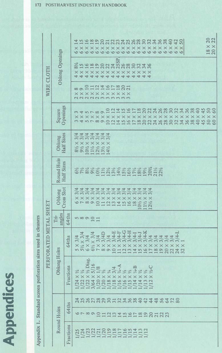
186
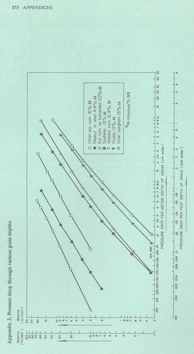
187

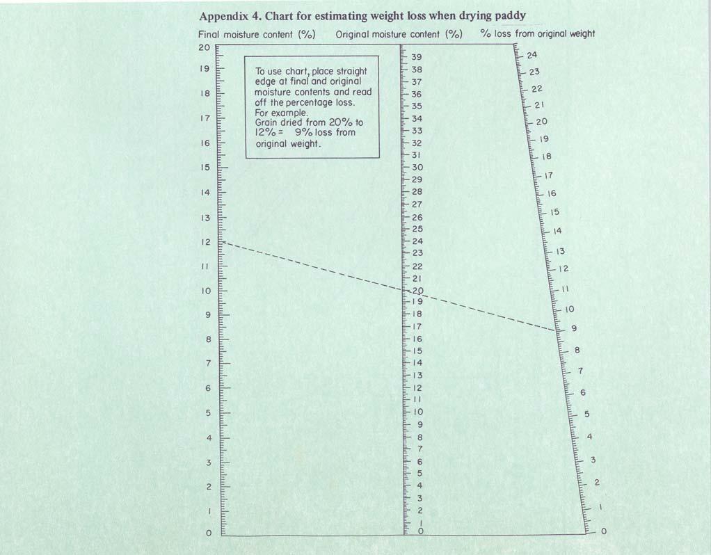
188 174 POSTHARVEST lndustry HANDBOOK


189 175 APPENDICES


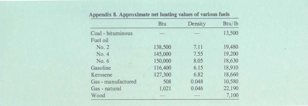
190 176 POSTHARVEST INDUSTRY HANDBOOK

191 177 APPENDICES

192 178 POSTHARVEST INDUSTRY HANDBOOK

193 179 APPENDICES
PART II. THE PRECLEANING OF PADDY
 PART II. THE PRECLEANING OF PADDY Prior to the actual milling operation, the paddy received from the farmer is cleaned in precleaning machines. Foreign matter or impurities are removed to protect the processing
ADJUSTMENTS FOR EFFICIENT AND PRECISION SEED CLEANING James Henderson Y
 ADJUSTMENTS FOR EFFICIENT AND PRECISION SEED CLEANING James Henderson Y One of the recent developments that has contributed to more efficient and exact seed cleaning is the metering hopper for screen and
Drying systems for grain and oil seeds. Schmidt-Seeger Eco Dry, Eco Cool, Eco Dry Flex.
 Drying systems for grain and oil seeds. Schmidt-Seeger Eco Dry, Eco Cool, Eco Dry Flex. Drying systems for grain and oil seeds. Schmidt-Seeger Eco Dry, Eco Cool, Eco Dry Flex. Proper conservation safeguards
Aerating Grain in Storage
 Aerating Grain in Storage Contents Moisture Movement in Metal Bins... 3 Air Flow Requirements... 3 Direction of Air Flow... 4 Air Distribution Methods... 5 Grain Pressure on Ducts... 6 Fan Operation...
Mill Master Machinery Pvt. Ltd.
 www.millmasterindia.com Mill Master Machinery Pvt. Ltd. Our Commitment : Quality, Delivery, Service COMPANY PROFILE Mill Master produces a comprehensive range of individual machines, complete integrated
The equipment for storage and transportation of grain
 The equipment for storage and transportation of grain About Company Grain House Сompany is a manufacturer of grain bins and wide range of material handling equipment in Ukraine. Grain House main partner
Drying principles and general considerations
 Drying principles and general considerations Drying Mechanisms In the process of drying heat is necessary to evaporate moisture from the grain and a flow of air is needed to carry away the evaporated moisture.
Seed Drying. 1. Surface moisture of the seed that initially removed by the drying air.
 Seed Drying The process of elimination of moisture from the seed is called drying. Seed drying should reduce the seed moisture content to safe moisture limits to maintain its viability and vigour during
DELTA CLEANERS 140 SERIES SEED PROCESSING CONVEYING DRYING SEED PROCESSING ELECTRONIC SORTING STORAGE TURNKEY SERVICE
 GB DELTA CLEANERS 140 SERIES SEED PROCESSING CONVEYING DRYING SEED PROCESSING ELECTRONIC SORTING STORAGE TURNKEY SERVICE EFFICIENCY AND PURITY IN THE CLEANING PROCESS CONSULTANCY BASED ON EXPERIENCE Accuracy
DOOSON GRAIN SYSTEMS. DOOSON CO., LTD. April 1, Venture. New Tech Export-Oriented Company INNO-BIZ. Goods
 Doosson Co., Ltd. www.doosonltd.com DOOSON GRAIN SYSTEMS DOOSON CO., LTD. April 1, 2017 World-Class Goods Venture New Tech Top Quality Excellent Product ISO 14001 Export-Oriented Company Product Manufacturer
AIR & SCREEN CLEANER MODEL: AS4 PRODUCT MANUAL
 AIR & SCREEN CLEANER MODEL: AS4 PRODUCT MANUAL Shown With Optional Air System Kit WARNING While the AS4 machine is in operation make sure all guards are in place and properly fastened. Do not wear loose
UNIVERSAL CLEANERS. Seed Conditioning And Processing Global Solution UNIVERSAL 240
 UNIVERSAL CLEANERS Seed Conditioning And Processing Global Solution UNIVERSAL 240 UNIVERSAL EXCELLPRE CLEANERS High Effective Pre-cleaning Performance Akyurek Technology develops and manufactures solutions
Evaluation Report 521
 Printed: February, 1987 Tested at: Portage la Prairie ISSN 0383-3445 Group 1(a) Evaluation Report 521 Forever 42 Dustless Grain and Grass Seed Cleaner A Co-operative Program Between ALBERTA FARM MACHINERY
Airblast Tech Tips Grit Recycling Systems - common questions and answers
 What type should I buy? The type of system that you will require depends on the method you like to use or feel will give you the lowest costs for completing the work you want to bid on. Just as every job
ZAW HTET AUNG PROGRAMME ASSOCIATE RADANAR AYAR
 ZAW HTET AUNG PROGRAMME ASSOCIATE RADANAR AYAR What is Radanar Ayar doing? 1. Seed Production 2. Crop Production 3. Second Crop Production (Cash Crop) 4. FAATU s Services Harvesting is - the process of
Grain and Soybean Drying on Georgia Farms
 Grain and Soybean Drying on Georgia Farms Table of Contents Principles of Grain Drying... 3 Drying Methods... 3 Moisture Levels for Safe Storage... 4 Equilibrium Moisture Content... 5 Bin Batch Drying...
Performance Evaluation of Reversible Air Flow Drying in Circulating Dryer
 Performance Evaluation of Reversible Air Flow Drying in Circulating Dryer Dai-Chyi Wang 1 and Yeun-Chung Lee 2 Abstract In Taiwan, rice is harvested with high moisture content (above 27%) and must be immediately
Milling ing and Mixing Systems
 Milling ing and Mixing Systems for the production of feed mixes from home-grown cereals Hammer mills, dry mixers, silos, pelleting equipment and o The trend is increasing towards using home-grown cereals
CLEANERS agroindustrial plants
 since 1956 CLEANERS agroindustrial plants 1 since 1956 After harvest choose THE MACHINES WITHOUT WORRY Mod. PPR ROTARY PRE-CLEANER Mod. PRA ROTARY CLENAER WITH ASPIRATION Mod. CR GRADER Mod. PA-I INCLINED
Aerating Farm -Stored Grain
 T Aerating Farm -Stored Grain oo MUCH M;OISTURE MIGRATION in stored grain may cause heating and molding - then spoilage and caking - in the top several inches. This can happen even in grain that has been
Performance Evaluation of Paddy Rice Pneumatic Dryer
 Performance Evaluation of Paddy Rice Pneumatic Dryer Krawee Treeamnuk, Suranaree University of Technology, Thailand Tawarat Treeamnuk, Suranaree University of Technology, Thailand Jittrarat Jokkew, Suranaree
2How does a vibratory fluid-bed dryer work?
 As appeared in April 2011 PBE Copyright CSC Publishing www.powderbulk.com Answers to five common questions about vibratory fluid-bed dryers Doug Schieber Carrier Vibrating Equipment A vibratory fluid-bed
SERVICE MANUAL AND PARTS CATALOG FOR YOUR SUPER 69D
 SERVICE MANUAL AND PARTS CATALOG FOR YOUR SUPER 69D Grain, Seed and Bean Cleaners 1440 SOUTH ADAMS STREET BLUFFTON, INDIANA 46714 (800) 248-8318 www.atferrell.com Updated February 23, 2011 OPERATION MANUAL
Efficient Cleaning and Grading
 Efficient Cleaning and Grading Pre-cleaning Reduces Costs for Drying and Ensures Safe Storage Kongskilde is one of the leading suppliers of pneumatic grain conveying equipment. Kongskilde introduced the
Parboiling in Thailand and the World
 Kasetsart University June 8th, 2011 Lecture abstract Parboiling in Thailand and the World Content Introduction History Relevance in the different cultures Markets - Facts and figures Process Preparation
Industrial Dust Aspiration Solutions. For optimal protection of plant and environment.
 Bühler GmbH DE-92339 Beilngries Deutschland T + 49 8461 701 0 F +49 8461 701 133 grain-logistics@buhlergroup.com Buhlergroup.com/grain-logistics GL_CB_Dust_Aspriation_Systems_EN_14004_02 Dust Aspiration
Management of In-Bin Natural Air Grain Drying Systems to Minimize Energy Cost
 Know how. Know now. EC710 Management of In-Bin Natural Air Grain Drying Systems to Minimize Energy Cost Thomas W. Dorn, Extension Educator With prices for all energy sources rising dramatically in recent
FLUID BED DRYERS, COOLERS AND MOISTURIZERS
 Bulletin FBD-08 FLUID BED DRYERS, COOLERS AND MOISTURIZERS For bulk foods, pharmaceuticals, and chemicals on a laboratory or production scale Self-contained system with circular fluid bed processor Greater
Grain Drying and Storage on Florida Farms 1
 CIR673 Grain Drying and Storage on Florida Farms 1 Michael T. Talbot 2 The drying and storage of agricultural products date back to the beginning of civilization. Drying of food and food products, the
CC196 Guide for Batch-Drying in a Bin
 University of Nebraska - Lincoln DigitalCommons@University of Nebraska - Lincoln Historical Materials from University of Nebraska- Lincoln Extension Extension April 2014 CC196 Guide for Batch-Drying in
RICE TECHNOLOGY Bulletin
 RICE TECHNOLOGY Bulletin Department of Agriculture Philippine Rice Research Institute (PhilRice) 1994 No. 9 PhilRice-UA BATCH DRYER Central Experiment Station Maligaya, Muñoz, 3119 Nueva Ecija Tel. Nos.:
APPLICATION PROFILE EXPLOSIONS IN CEMENT PLANTS EXPLOSIONS IN CEMENT PLANTS CEMENT PLANT EQUIPMENT WITH HIGHEST EXPLOSION POTENTIAL. Form No.
 APPLICATION PROFILE EXPLOSIONS IN CEMENT PLANTS Cement manufacturing is one of the largest mineral commodity industries in the United States, with an estimated production capacity of greater than 73 million
Pulse Jet Baghouse ASTEC PULSE JET BAGHOUSE. for Asphalt Facilities
 Pulse Jet ASTEC PULSE JET BAGHOUSE for Asphalt Facilities ASTEC PULSE JET BAGHOUSE FOR ASPHALT MIXING PLANTS Astec baghouses deliver superior performance and efficiency, while helping your plant meet
Contents. 1. Seed Harvesting, Drying, Packaging, Pre- Treatment and Storage : - Processing & Quality Assurance
 Contents 1. Seed Harvesting, Drying, Packaging, Pre- Treatment and Storage : - Processing & Quality Assurance Seed Harvesting, Drying, Packaging, Pretreatment and Storage : - Processing & Quality Assurance
TECCON. 2,5 to 10,0 t / H Water evaporation RATE
 TECCON BELT DRYER 2,5 to 10,0 t / H Water evaporation RATE Installation of belt dryer 2 TECCON belt dryer Belt dryer 2,5 to 10,0 t / H Water evaporation RATE 1 Zentrales Element im Pelletswerk Norica ist
GRAIN STORAGE TURNKEY CONVEYING DRYING SEED PROCESSING ELECTRONIC SORTING STORAGE TURNKEY SERVICE
 GB GRAIN STORAGE TURNKEY CONVEYING DRYING SEED PROCESSING ELECTRONIC SORTING STORAGE TURNKEY SERVICE GRAIN STORAGE OPTIMUM GRAIN STORAGE FOR BETTER UTILIZATION OF NATURE S RESOURCES Cimbria is one of the
Solid biofuel solutions
 Solid biofuel solutions Clean heat with locally produced fuel Solid biofuels are the individually most important component in the conversion to a sustainable energy mix. Heat production from wood based
LDDC Series Double-Deck Drum Pre-cleaner. Instruction Manual LAMBTON MACHINERY(ZHENGZHOU)CO. LTD
CO. LTD") LDDC Series Double-Deck Drum Pre-cleaner Instruction Manual LAMBTON MACHINERY(ZHENGZHOU)CO. LTD. 2015.08 Index Double-Deck Drum Pre-cleaner... 1 Instruction Manual... 1 Ⅰ. General Introduction... 3 Ⅱ.
LDDC Series Double-Deck Drum Pre-cleaner Instruction Manual LAMBTON MACHINERY(ZHENGZHOU)CO. LTD. 2015.08 Index Double-Deck Drum Pre-cleaner... 1 Instruction Manual... 1 Ⅰ. General Introduction... 3 Ⅱ.
MADE IN THE USA FOUNDRY & FORGING AIRLESS SHOT BLAST & PARTS WASHING EQUIPMENT
 MADE IN THE USA FOUNDRY & FORGING AIRLESS SHOT BLAST & PARTS WASHING EQUIPMENT 06-2011 CHAINBELT FLOW THROUGH BLASTERS CB 3624 This type of system offers the potential for reducing blaster operation and
Pneumatic In-Line. Tru-Balance Sifters
 Pneumatic In-Line Tru-Balance Sifters What is the In-Line Sifter? Flow Scheme The In-Line Tru-Balance Sifter works like our multi-sieve gravity flow sifters, except that it operates under the pneumatic
venting method will work for all pressure conveying systems, analyzing your available equipment, your material s characteristics, and your conveying c
 Six practical ways to handle rotary leakage Jonathan O. Thorn MAC Equipment Because of the way a rotary is designed, it s normal for a small amount of conveying to leak back through the as it s bulk solid
CLEANING PRODUCT 10/22/2014 CLEANING PRODUCTS DEFINITION CLEANING, SORTING, AND GRADING
 CLEANING, SORTING, AND GRADING DEFINITION Cleaning: remove foreign objects or materials which are not similar from a product. Sorting: separate product into several quality fraction based on the shape,
Potato processing systems
 Potato processing systems Our company For 5 generations, Spiessens has aimed for quality and durability. Originally an expert in the development of farming machinery, Spiessens steadily evolved into the
SQ SERIES DRYERS GRAIN MANAGEMENT SYSTEMS
 SQ SERIES DRYERS SQ STORAGE HANDLING CONDITIONING STRUCTURES GRAIN MANAGEMENT SYSTEMS SQ CHOICE OF DRYING MODES FULL HEAT CONTINUOUS FLOW DRYERS SQ D Series Full Heat Single Zone FULL HEAT CONTINUOUS FLOW
AEC Sales & Support Research Equipment Phone Fax East Main Street
 Research Equipment Research Accessories and Equipment COB INCLINE CONVEYOR AND COB BIN - Incline belt conveyors are designed to transfer cobs into a cob bin for convenient disposal. Cob incline conveyor
RGO Sales North Battleford, SK
 RGO Sales North Battleford, SK 306-445-0674 Owners Manual for Light Foot Grain Cleaners Warning: WHILE THE MACHINE IS IN OPERATION MAKE SURE ALL GUARDS ARE IN PLACE AND PROPERLY FASTENED. DO NOT WEAR LOOSE
ANNEXURE-A SPECIFICATIONS FOR HOT MIX PLANT
 ANNEXURE-A SPECIFICATIONS FOR HOT MIX PLANT COLD AGGREGATE BIN FEEDER FEEDING HOPPERS Four Nos. Cold aggregates hopper with a heaped capacity of approx. 52 T. Wide opening bin width to accommodate different
ECO-MASTER DRYER DRYING CONVEYING DRYING SEED PROCESSING ELECTRONIC SORTING STORAGE TURNKEY SERVICE
 GB ECO-MASTER DRYER DRYING CONVEYING DRYING SEED PROCESSING ELECTRONIC SORTING STORAGE TURNKEY SERVICE THE EFFICIENT AND SUSTAINABLE DRYING SOLUTION LEADING SUPPLIER OF ADVANCED DRYING TECHNOLOGY During
RECYCLING OF ADHESIVE TAPE WASTE WITH THE PLAST AGGLOMERATOR SYSTEM
 RECYCLING OF ADHESIVE TAPE WASTE WITH THE PLAST AGGLOMERATOR SYSTEM Frank Maué, Product Sales Manager, Pallmann Maschinenfabrik GmbH & Co. KG, Zweibrücken, Germany Abstract During the production and processing
Lightweight Concrete Mix Profitable Using Heavyweight Batch Mixer
 DRY BULK BLENDING EQUIPMENT Rotary Batch Mixers Ribbon/Paddle/ Plow Blenders Rotary Continuous Blenders High Intensity Continuous Blenders Vee-Cone Blenders Fluidized Bed Mixers SIZE REDUCTION EQUIPMENT
ASPHALT PLANT. AtlasTechnologiesIndia.com
 ASPHALT PLANT Available as stationary and semi-mobile. VARIANTS: ABP 80 (80 tph), ABP 120 (120 tph), ABP 160 (160 tph) Capacities above 160 tph are tailor made. AtlasTechnologiesIndia.com AGGREGATE FEEDER
I. C O N T E N T S T A N D A R D S
 Introductory Physics, High School Learning Standards for a Full First-Year Course I. C O N T E N T S T A N D A R D S and radiation between objects or regions that are at different temperatures. 3.1 Explain
International Process Plants
 International Process Plants Stock #600344 Oilseed Preparation & Conditioning Line 300 MTPD Visit us at: www.ippe.com General OverviewOverview 300 metric tons/day Capacity Used for Only 5 Years Stored
POST HARVEST. Food and Agriculture Organization of the United Nations
 POST HARVEST Food and Agriculture Organization of the United Nations POST HARVEST 1.- Vegetable processing - general information The vegetables may be marketed in different ways. The "in-natura" form is
[1] Lecture 2 Particulate emission control by mechanical separation & wet gas scrubbing
![[1] Lecture 2 Particulate emission control by mechanical separation & wet gas scrubbing](/thumbs/89/99244801.jpg "[1] Lecture 2 Particulate emission control by mechanical separation & wet gas scrubbing") [1] Lecture 2 Particulate emission control by mechanical separation & wet gas scrubbing PARTICULATE EMISSION CONTROL BY MECHANICAL SEPARATION The basic mechanism of removing particulate matter from gas
[1] Lecture 2 Particulate emission control by mechanical separation & wet gas scrubbing PARTICULATE EMISSION CONTROL BY MECHANICAL SEPARATION The basic mechanism of removing particulate matter from gas
Complex Solutions For Grain Storage & Нandling
 Complex Solutions For Grain Storage & Нandling CONTENTS About Us Complex Solutions 4 6 Our Products: Grain Bins Grain Dryers Conveying Equipment Grain Cleaners Auxiliary Equipment Our Services Our Projects
A Regional Research and Dissemination Programme. Phase III SOLAR BOX DRYER DESIGN, CONSTRUCTION AND OPERATION MANUAL
 RENEWABLE ENERGY TECHNOLOGIES IN ASIA: A Regional Research and Dissemination Programme Phase III SOLAR BOX DRYER DESIGN, CONSTRUCTION AND OPERATION MANUAL Energy Field of Study School of Environment, Resources
DFE T ECHNOLOGY. At Conceptronic, the design and management process for reflow soldering systems is called Dynamic Flow Engineering, or DFE.
 DFE T ECHNOLOGY As components become smaller, component mixes become more diverse, and board densities continue to increase, the processes of packaging, interconnection, and assembly are challenging the
PUMPKIN SEED HARVESTING TECHNOLOGY 2019
 PUMPKIN SEED HARVESTING TECHNOLOGY 2019 Moty GmbH Piesing 20, AT 4846 Redlham office@moty.at www.moty.at Engineering changes, literal mistakes and prices are subjects to change Your reliable partner for
Drying Groundnuts: Adapting the EasyDry M500 Portable Maize Dryer for Groundnuts
 Drying Groundnuts: Adapting the EasyDry M500 Portable Maize Dryer for Groundnuts (the EasyDry G600) AflaSTOP: Storage and Drying For Aflatoxin Prevention January 2017 PAGE 2 OF 10 TABLE OF CONTENTS I.
Grain Drying of Malting Barley
 Grain Drying of Malting Barley Return to AGWEST Index Farmnote 101/2000 By Roslyn Jettner, Barley Industry Development Officer Agriculture Western Australia, and Linda Price, Regional Officer, The Grain
StaticArc Screens. Water and Effluent Treatment
 Water and Effluent Treatment StaticArc Screens Screen Services Specialty screens and equipment for industrial, petrochemical, mining, and water treatment applications Page 2 StaticArc Screens: Screen Services
CC196 Revised with no date Guide for Batch- Drying in a bin
 University of Nebraska - Lincoln DigitalCommons@University of Nebraska - Lincoln Historical Materials from University of Nebraska- Lincoln Extension Extension April 2014 CC196 Revised with no date Guide
A. T. FERRELL COMPANY, INC.
 Clipper Seed Cleaner SITE PREPARATION MANUAL A. T. FERRELL COMPANY, INC. Since 1869 Manufacturers of Clipper Grain & Seed Conditioning Equipment 1440 South Adams Street Bluffton, IN 46714 USA Telephone:
Drying rate 1. Section B to C of the curve, known as the constant rate periods, represents removal of unbound water from the product.
 Drying rate 1 Drying process of a material can be described as a series of steps in which drying rate plays a key role. Following figure shows typical drying rate curve for a constant drying conditions.
Ontario Fire Code SECTION 5.10 COMBUSTIBLE DUST PRODUCING PROCESSES. Illustrated Commentary. Office of the Ontario Fire Marshal
 Ontario Fire Code SECTION 5.10 COMBUSTIBLE DUST PRODUCING PROCESSES Illustrated Commentary Office of the Ontario Fire Marshal Combustible Dust Illustrated Commentary 1 Mechanical Exhaust Systems 5.10.1.1.
Pneumatic Grain Conveying
 Pneumatic Grain Conveying Flexible Pneumatic Conveying Solutions Moving agriculture ahead High Pressure Blowers Outlet cyclone Outlet cyclone Blower Receiving hopper Blower Injector Pressure conveying
Using Portable Spot Air Conditioners in Industrial Applications
 Using Portable Spot Air Conditioners in Industrial Applications Cooling People, Processes and Equipment In today s highly competitive manufacturing sector, companies are constantly looking for new ways
More heat energy means more of what type of energy? Does the mass change? So, what must change? What is the same in both containers?
 Quest Chapter 21-23 # Problem Hint 1 When a container of gas is heated, what happens to the average speed of its molecules? 1. Additional information is needed. 2. increases 3. doesn t change 4. decreases
ASPHALT PLANT. atlasindustries.in
 ASPHALT PLANT Available as stationary and mobile. STATIONARY VARIANTS: DM 45 (40-60 tph), DM 50 (60-90 tph), DM 60 (90-120 tph) MOBILE VARIANTS: MDM 45 (40-60 tph), MDM 50 (60-90 tph), MDM 60 (90-120 tph)
Quality & Service Since For the Reduction of Metal Turnings to Shoveling Chips for Briquetting or Pneumatic Conveying
 Quality & Service Since 1908 For the Reduction of Metal Turnings to Shoveling Chips for Briquetting or Pneumatic Conveying Features & Benefits Why it will pay you to have our Metal Turnings Crusher in
Introduction to Bulk Solids. The Basics
 Introduction to Bulk Solids The Basics Glossary of Terms Angle of Repose This is the angle that material will naturally mound up when filling a tank, or down when discharging a tank. Dielectric Constant
mixed flow dryer one of the most efficient dryers on the market. Now CSA approved for Canada in 16, and 24' models.
 MIXED FLOW DRYER mixed flow dryer one of the most efficient dryers on the market. For over 50 years, NECO has specialized in agricultural equipment engineering and manufacturing. NECO produces market leading
Bühler Drying System for Paddy proven to be gentle, barely creating brokens
 Media Release Performance test result by Dr. Anna N. Vega, 16.05.2017 Bühler Drying System for Paddy proven to be gentle, barely creating brokens Bühler AG CH-9240 Uzwil, Switzerland T +41 71 955 11 11
A D VA N C E D E L E C T R O N I C G R A I N D RY I N G C O N T R O L S S Q S E R I E S D R Y E R S
 SQ SERIES DRYERS SM SQ Stainless Steel Outer Skins Stainless steel outer 18-gauge perforated skins are standard on all SUPERB ENERGY MISER SQ Series Dryers for a lifetime of satisfaction. With proper care
MC1 NEWTON GRAIN CLEANER STATIONARY OPERATIONS MANUAL
 MC1 Mid-Continent Industries, Inc. 1801 SE 9 th ST., PO Box, Newton, KS 67114 316-283-9648* 800-279-6812* Fax 316-283-0745 NEWTON GRAIN CLEANER STATIONARY OPERATIONS MANUAL Newton Grain Cleaner Operations
TOWER DRYERS TOTA TOT L VA AL V LUE. TOTA ALUE. TOT L SYSTEMS. AL SYSTEMS.
 TOWER DRYERS TOTAL VALUE. TOTAL SYSTEMS. 1 GSI FEATURES 1 Gravity inlet does not require leveling auger, reducing the number of moving parts. 2 3 2 Self cleaning cushion box on plenum roof reduces grain
Evaluation Report 422
 Printed: September, 1985 Tested at: Portage la Prairie ISSN 0383-3445 Group: 1(a) Evaluation Report 422 Harvey Gjesdal Five-In-One Rotary Seed Cleaner A Co-operative Program Between ALBERTA FARM MACHINERY
Design of an Efficient Drying System
 Design of an Efficient Drying System Kyle Dollins Becca Hoey Michael Matousek BAE 4023 Overview Problem Statement Sponsor Information Current Process Fall Design Concepts Concept Selection Calculations
Design Considerations for Abrasive Blast Rooms & Recovery Systems
 Clemco Industries Corp. presents Design Considerations for Abrasive Blast Rooms & Recovery Systems by Bob Kerr Business Development Manager Report Documentation Page Form Approved OMB No. 0704-0188 Public
ASPHALT PLANT. atlastechnologiesindia.com
 ASPHALT PLANT MOBILE PLANT VARIANT: MDM 25 (20-30 tph) atlastechnologiesindia.com AGGREGATE FEEDING CONVEYOR AGGREGATE FEEDER In our mobile asphalt drum mix plant all the four bins are fitted with individual
ROTARY DRYER CONSTRUCTION
 ROTARY DRYER The Rotary Dryer is a type of industrial dryer employed to reduce or to minimize the liquid moisture content of the material it is handling by bringing it into direct contact with a heated
The Economical Approach to Specialized Finishing and Surface Preparation
 The Economical Approach to Specialized Finishing and Surface Preparation EMPIRE: A LEADER IN AIR-BLAST TECHNOLOGY FOR OVER 60 YEARS Empire has specialized in designing and manufacturing abrasive-blasting
ROTO-PACKER The Originals. Made by HAVER. Progress and Quality for the 21st Century HAVER & BOECKER HAVER & BOECKER. Information HAVER & BOECKER
 HAVER & BOECKER HAVER & BOECKER Progress and Quality for the 21st Century The HAVER ROTO-PACKER series RL designates a rotating valve type bag filling machine (with 3, 4, 6, 8, 10 or 12 spouts) according
By Authority Of THE UNITED STATES OF AMERICA Legally Binding Document
 By Authority Of THE UNITED STATES OF AMERICA Legally Binding Document By the Authority Vested By Part 5 of the United States Code 552(a) and Part 1 of the Code of Regulations 51 the attached document has
Storing grain to reduce postharvest losses and protect its quality
 Storing grain to reduce postharvest losses and protect its quality Facts Current world population is expected to reach 10.5 billion by 2050 (UN March, 2013). This increase translates into 33% more human
POD CEAL. Retains Yield Potential and Quality in Pod Bearing Crops AGRICULTURAL
 POD CEAL Retains Yield Potential and Quality in Pod Bearing Crops AGRICULTURAL PRODUCT COMPOSITION: Polymer of Cyclohexane, 1 methyl-4 (1-methylethyl) READ THE LABEL BEFORE USING KEEP OUT THE OF CHILDREN
Sedimentation. Photo Credit: Virginia Department of Health
 Sedimentation. Photo Credit: Virginia Department of Health Objective In this lesson we will answer the following questions: How does sedimentation fit into the water treatment process? What zones are present
HOW TO SELECT AN INDIRECT THERMAL TECHNOLOGY FOR INDUSTRIAL MATERIALS PROCESSING
 white paper HOW TO SELECT AN INDIRECT THERMAL TECHNOLOGY FOR INDUSTRIAL MATERIALS PROCESSING Better Thermal Processing Results Begin with Selecting the Right Technology Authored by Rob Grady Director of
JCD Jog Conveyor Dryer
 JCD Jog Conveyor Dryer Purposes & and Principles of Operation Jog Conveyor Dryers are mainly used after the coating process to prevent wet kernels from clumping together during bagging off. Due to very
BALE BREAKER AND OPENERS
 BALE BREAKER AND OPENERS 13 Automatic Bale Plucker is used to mechanically strip fibres from pressed bales and automatically drop the fibre on to the feed table of the opening machinery at the beginning
ASPHALT PLANT. atlastechnologiesindia.com. MOBILE VARIANTS: MDM 45 (40-60 tph), MDM 50 (60-90 tph), MDM 60 ( tph)
, MDM 50 (60-90 tph), MDM 60 ( tph)") ASPHALT PLANT Available as stationary and mobile. STATIONARY VARIANTS: DM 45 (40-60 tph), DM 50 (60-90 tph), DM 60 (90-120 tph) MOBILE VARIANTS: MDM 45 (40-60 tph), MDM 50 (60-90 tph), MDM 60 (90-120 tph)
ASPHALT PLANT Available as stationary and mobile. STATIONARY VARIANTS: DM 45 (40-60 tph), DM 50 (60-90 tph), DM 60 (90-120 tph) MOBILE VARIANTS: MDM 45 (40-60 tph), MDM 50 (60-90 tph), MDM 60 (90-120 tph)
INSTRUCTIONS FOR USE OF FLOUR RECEPTACLE (Mills are shipped with either receiver bag or canister-not both)
") Subject: A-33 Instructions Adjustment instructions for the A-33X and Jiffy flour mill. Disregard adjustment steps 1 through 6 on page 2. The mill is adjusted from a fine to a coarse grind by moving the
Subject: A-33 Instructions Adjustment instructions for the A-33X and Jiffy flour mill. Disregard adjustment steps 1 through 6 on page 2. The mill is adjusted from a fine to a coarse grind by moving the
Renewable energy-based fruit dryers 1
 Renewable energy-based fruit dryers 1 Arnold R. Elepaño and Karen T. Satairapan 2 I. INTRODUCTION Drying of fruit is important for long-term storage without further deterioration in the quality of the
PRINCIPLES OF GRAVITY SEPARATION Jim Thomas. Engineer Oliver Mfg. Company Rocky Ford, Colorado
 PRINCIPLES OF GRAVITY SEPARATION Jim Thomas Engineer Oliver Mfg. Company Rocky Ford, Colorado All gravity separators utilize the same principles to effect a separation. Once these principles are understood,
EasyDry. Grain Drying Systems
 EasyDry Grain Drying Systems Grain Drying & Storage System Raise your standards high, with EasyDry. EasyDry enhances your on-farm grain storage system efficiency and overall grain quaility. EasyDry from
Mixed Flow Dryer. One of the most efficient dryers on the market.
 Mixed Flow Dryer Mixed Flow Dryer. One of the most efficient dryers on the market. For over 50 years, NECO has specialized in agricultural equipment engineering and manufacturing. NECO produces market
Quality Construction Equipment
 Quality Construction Equipment ASPHALT BATCH MIX PLANT ANP Series - 60 to 240 tph ASPHALT BATCH MIX PLANT Apollo has always been proactive in rising to customer demands and expectations by providing quality
150Tons Satake Rice Mill List
 BART YANG TRADES ADDRESS: ROOM 603 SOHO - BUILDING - B, XIANGSHENG STREET, ZHENGZHOU CITY, HENAN PROVINCE, HENAN. TEL: +86 371 53309394 E-MAIL: info@bart-trades.com MOBILE:+86 185 3712 1208 150Tons Satake
SOME PROBLEMS IN DEVELOPING MECHANICAL GRAIN DRYER AND RESEARCH IMPROVEMENT
 SOME PROBLEMS IN DEVELOPING MECHANICAL GRAIN DRYER AND RESEARCH IMPROVEMENT Nursigit Bintoro Dept. of Agricultural Engineering, Fac. of Agricultural Technology, Gadjah Mada University, Yogyakarta, Indonesia