SWIMMING POOL HEAT PUMP UNIT
|
|
|
- Eric Warner
- 6 years ago
- Views:
Transcription


1 SWIMMING POOL HEAT PUMP UNIT Installation & Instruction Manual Rev. WF PHP
2 Advice to customers 1. Please read this manual carefully before installing the product, otherwise you could damage the heat pump, injure users or incur financial losses. 2. As advances in science and technology are made, the product will also improve. We would therefore urge you to keep up to date with the latest products. 3. If you require further technical information, please contact your local distributor. 4. Note: 4.1 Before installing the heat pump, check that your local power supply meets the requirements of the heat pump. For full details, check the unit's label or the performance information that appears in this manual. 4.2 Fit the electrical protection devices in compliance with local regulations. 4.3 You must earth the heat pump in order to prevent electric shocks caused by an unexpected short circuit in the unit. 4.4 There is a diagram of the wiring in this manual. 4.5 For safety reasons, you should not replace or repair the heat pump yourself. If it required repairs, please contact your local distributor for assistance. 4.6 Do not place objects inside the heat pump while it is working. They could come into contact with the fan and damage it, as well as cause accidents (especially in the case of children). 4.7 Do not use the heat pump without the grille or plaque, as this could cause accidents or the unit to malfunction. 4.8 If the unit fills with water, contact your local distributor immediately. The unit may only be reset following a full inspection by a qualified service engineer. 4.9 Unqualified service engineers may not adjust the unit's switchboards, valves or controllers. *This appliance can be used by children aged from 8 years and above and persons with reduced physical, sensory or mental capabilities or lack of experience and knowledge if they have been given supervision or instruction concerning use of the appliance in a safe way and understand the hazards involved. Children shall not play with the appliance. Cleaning and user maintenance shall not be made by children without supervision.
3 Contents 1. Performance and installation 1.1 Performance and features Working principles Location of heat pump installation Distance from the pool Installation of the check-valve Pool system set up Connecting the by-pass Warning First time start-up Condensation Operation of heat pump 2.1 Operation of control display Control display illustration Power ON/OFF heat pump How to change mode Adjust desired water temperature Check and set parameters Setting Time Setting Timer on/ Timer off Cancellation of Timer off Key pad lock Operation of APP controller workingprincipleofappcontrol Set up of the network APP operation Protection systems 3.1 Water flow switch Refrigerant gas high and low pressure protection Overheating protection on the compressor Automatic defrost control Temperature difference between inflowing and outflowing water Low temperature cut-out Anti-frost protection during winter First anti-frost protection Second anti-frost protection Direction 4.1 Swimming pool water chemistry Heat pump winterizing Restarting the pump after winter Check-up Maintenance and inspection 5.1 Maintenance Trouble shooting guide Failure code table overview Name plate & wiring diagram 6.1 Name plate Wiring diagram...26


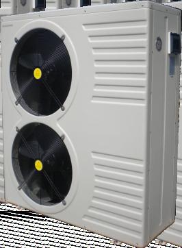
4 1. Performance and installation 1.1 Performance and features High efficiency With a COP value up to 5.0 our heat pumps are very efficient when transferring heat from the air to the swimming pool water. You can save as much as 80% of cost compared to an electrical heater. Long life-span The heat exchanger is made of PVC & Titanium tube, which can withstand and prolong exposure to swimming pool water. Easy control and operation The unit is very easy to operate: simply switch it on and set the desired pool water temperature. The system includes a micro-computer controller, allowing all operation parameters to be set. Operation status can be displayed on the controller with LED display. 1.2 Working principles Cooler De-energized Air Compressor Swimming pool Evaporator Pump Air flow Compressor Water flow in Heat exchanger Air flow Water flow out Warm Air Fan Evaporator (Energy Collector) Pool Filter Condenser (Water Heat Exchanger) Capillary Tube Heat pumps utilize the sun's free heat by collecting and absorbing energy from the outside air. This energy is then compressed and transferred to the pool water. Your existing water pump circulates the water through the heater, usually next to the pool equipment, and the water warms up. The heat pump timer could be set to operate during daylight hours, for example, usually 9am to 5pm. The unit contains a fan that draws in outside air and directs it over the surface of the EVAPORATOR (energy collector).the liquid refrigerant within the EVAPORATOR coil absorbs the heat from the outside air becomes a gas. The warm gas in the coil passes through the COMPRESSOR concentrating and increasing the heat to form a very hot gas which then passes to the CONDENSER (water heat exchanger).it is here that the heat exchange occurs as the hot gas gives off heat to the cool swimming pool water circulating through the coil. The pool water becomes warmer, and the hot gas cooling as it flows through the CONDENSER coilreturns to its liquid form and, after passing on through the CAPILLARY TUBE, the whole process begins again. The state of the heat pump technology can efficiently collect heat from the outside air down to the 7 to 10 range. For tropic and subtropical climates, this means that the pool can be maintained at 26 to 32 1
5 1.3 Location of heat pump installation The unit will perform well on any location provided three factors are present: 1. Fresh air - 2. Electricity - 3. Pool filter piping The unit may be installed virtually anywhere outdoors providing minimum distance requirements are met with respect to other objects (see diagram below).for indoor pools please consult your installer. If the unit is placed in a windy area, no problems occur with e.g. the pilot light, as opposed to what is often the case with gas heaters. Attention: Do not place the unit in an enclosed area with a limited air volume where the unit's discharged air will be re-circulatedor near shrubs that could block the air inlet. These locations deny the unit a continuous fresh air supply, which reduces its efficiency and may prevent adequate heat yield. See diagram below for minimum required distances. Model:Horizontal Unit Not less than 500mm Airin Airin Not less than 500mm Airout Not less than 500mm Not less than 2000mm Free space requirement for the horizontal heat pump Cautions - Do not put your hands or any other object into the air outlet and fan. It could damage the heat pump and cause injuries. - In case any abnormality was found in the heat pump, please cut off the power at once and contact a professional technician. - It is strongly suggested to place a guard around the machine to keep children away from the heat pump. 2
6 1.4 Distance from the pool Normally, the pool heat pump is installed within a 7.5 meter radius of the pool. The greater the distance from the pool, the greater the heat loss from the piping. Since the piping is buried for the most part, heat loss is minimal for distances of up to 30 meters (15 meters to and from the pump= 30 meters total), unless the soil is wet or the water level is high. Heat loss per 30 meters could roughly be estimated at 0.6 kw-hour (2000 BTU) for every 5 temperature difference between the pool water and the soil surrounding the pipe, which translates to an operation time increase of 3-5%. 1.5 Installation of the check-valve Attention- When using automatic chlorine and PH dosage systems, it is of uttermost importance to protect the heat pump from high concentrations of these chemicals that could corrode the heat exchanger. Therefore, such systems should add the chemicals in the conduits located DOWNSTREAM of the heat pump and it is recommended to install a check-valve in order to prevent backflow when there is no water circulation. Damage to the heat pump caused by disregarding any of these recommendations will invalidate the warranty. Check-valve Filter Chlorinator P-trap Check-valve Water Pump Swimming Pool 3
7 1.6 Pool system set up Heat Pump Water processor Side connection valve Outlet Power cable inlet Inlet Condensed water draining pipe Draining nozzle Discharge water to pool Pool water inlet Water pump Filter 1.7 Connecting the by-pass T o p o o l BY-PASS Valve 1 Valve 2 Valve 3 F r o m f i l t e r OUT IN HEATPUMP 4

 Important Although the heat pump is electrically isolated from the rest of the unit, this only prevents the passage of electricity to or from the pool water.")
8 1.8 Warning: - Do not place your hand or any other objects into the air outlet and fan. It could damage the heat pump and cause injuries; - In case of any abnormality with the heat pump, cut off the power immediately and contact a professional technician; - It is strongly advised to place a protective guard around the unit to keep children away from the heat pump. - An authorized electrician must connect the Heat Pump to the power. (230V 1ph or 400V 3ph) Important Although the heat pump is electrically isolated from the rest of the unit, this only prevents the passage of electricity to or from the pool water. Grounding the unit is still required to protect yourself from short circuits inside the unit. Make for adequate ground connection. Check if the electrical mains voltage corresponds with the operating voltage of the heat pump prior to hooking up the unit. POWER CONNECTION WATER PUMP POWER SUPPLY WATER PUMP POWER SUPPLY 230V / 1ph / 50Hz V / 3ph / 50Hz Model Voltage (V) Fuse (A) Current (A) 3.8kW 4.5kW 5.6kW 7.8kW 9.5kW 12.5kW 14.0kW 17.0kW 21.0kW 14.0kW 17.0kW 21.0kW 26.0kW 31.0kW x380 3x380 3x380 3x380 3x Cable diameter (mm ) (for max. Length of 20 meters) 2x x x x x x x x x x x x x x
9 1.9 First time start-up Note- In order for the unit to heat the pool (or spa), the filter pump must be running so that the water can circulate through the heat pump. Without this circulation, the heat pump will not start. When all connections have been made and checked, the following steps should be followed: 1). Turn on the filter pump. Check for leaks. 2). Turn on the electrical power supply to the unit, then press the ON/OFF key on the electronic control panel. The unit should start when the time delay period has elapsed. 3). When the unit has been running for a couple of minutes, check if the air leaving the unit is cooler than the ambient temp. 4). Check the performance of the flow switch as follows: with the unit running turn the filter pump off. The unit should also switch off automatically. 5). The unit and the filter pump should run 24 hours a day until the desired pool water temperature has been reached. Once the set temperature is reached, the unit will switch itself off. As long as the filter pump is running, the unit will restart automatically when the temperature of the pool water drops more than 1 C below the set temperature. Depending on the starting temperature of the pool water and the air temperature, it can take several days for the water to reach the desired temperature. Covering the pool can drastically reduced this period. Water flow switch the unit is equipped with a flow switch that is switched on when enough water has flowed through the unit and that is switched off when the water flow becomes too low. (E.g. When the filter pump is switched off). Time delay the unit is equipped with a built-in 3-minute start delay included to protect electrical components and contacts. After this time delay, the unit will automatically be restarted. Even a brief interruption of the power supply will activate the start delay and prevent the unit from starting immediately. Additional interruptions of the power supply during the delay period will have no effect on the 3-minute countdown Condensation When the swimming pool water is being heated by the heat pump, the incoming air is cooled down quite a bit, which can cause condensation on the fins of the evaporator. Condensed volumes can attain several litres per hour under high atmospheric humidity. Sometimes, this is wrongfully interpreted as a water leak. 6
10 2. Operation of heat pump 2.1 Operation of control display Control display illustration: MIN When heat pump is supplied with power, controller will display with full screen, shows that it is already connected. If connection fails in 10 seconds, please check connections between communication cable and control display, or replace with another control display. Button functions: button: ON/OFF switch to start or stop heat pump. TIMER button:timer button to set timer on and timer off. MODE button: To switch between heating, cooling and auto mode. To enter parameter settings and confirm settings. + - button: To increase or decrease value. Icons definitions: --heating icon, showing heat pump is in heating mode. --cooling icon, showing heat pump is in cooling mode. --auto icon, showing heat pump is in auto mode. --alarm icon, showing system alarm. --key pad lock icon, showing buttons on the control display are locked. --wifi signal. Note: 1. Heat pump is not equipped with electric heater internally, only provides terminal for external connection. 2. Fan speed is automatically controlled by ambient temperature, not manually. 7
11 2.1.2Power ON/OFF heat pump Press button 5s to switch on heat pump. Once the heat pump is powered on all related running component icons will be lightened as well as POWER displayed in the middle of display to show system is in running status. Figure 2-2 shows heat pump in standby status and figure 2-3 shows heat pump in running status. The left temperature shows flow water temperature while the right temperature is the return water temperature. running status Figure 2-2 Figure How to change mode Press MODE button to select auto, heating or cooling mode, related indicator icon will be lightened as a symbol to show heat pump is in either auto, heating or cooling mode. Auto mode Heating mode Cooling mode Figure 2-4 8
12 2.1.4 Adjust desired water temperature 1.First select desired mode, auto, heating or cooling. 2.No matter the heat pump is under standby status or running status, press + or -, display will show the desired water temp. of selected mode with a flashing value, then change the water temp. by moving + or - as requested Check and set parameters When heat pump is in standby status, press MODE button for 5 seconds display will show parameter number with value flashing together. Move + and - button to check required parameter settings. Select desired parameter and press MODE button for resetting parameter. Parameter number stays fixed while parameter value remains flashing. Move + and - button to adjust the value. Press MODE button to confirm the setting. Without any further movement on the display button in 2min it will return to main interface automatically. See Parameter table for more details. Figure 2-5 parameter value Note: All parameters can be changed ONLY under standby status! Setting Time Press TIMER button 5s in a quick stop to activate time setting. When hour numbers are flashing it is available for revision, move + or - to fix hour numbers. Press TIMER button to confirm hour setting. Minute numbers start flashing once the hour numbers are confirmed, move + or - to fix minute numbers. Press TIMER button to confirm minute setting. 9
13 2.1.7 Setting Timer on/ Timer off Press TIMER button to enter timer setting for TIMER 1. Hour data will be flashing with ON, move + or - to set it. Confirm timer on hour setting by pressing TIMER button. Minute data starts flashing once hour setting is confirmed, move + or - to set it. Confirm timer on minute setting by pressing TIMER button. Press TIMER button, and then MODE button. The signal will flash, then press + button to change to TIMER 2 or TIMER 3. Hour data will be flashing with ON, move + or - to set it. Confirm timer on hour setting by pressing TIMER button. Minute data starts flashing once hour setting is confirmed, move + or - to set it. Confirm timer on minute setting by pressing TIMER button. Once Timer on is set and confirmed Timer off will be activated. Follow the same steps as setting Timer on to set Timer off Cancellation of Timer off If the starting time is set to be the same as the finishing time, then the timer function is off. The signal will be off. Timer ON /OFF key and locked Figure Key pad lock Press + and - button together for 5 seconds, display will show lock icon. Do this again to unlock. 10
14 Parameter table overview (1) Parameter Control Display APP Description Range Default Remark F0/00 Temp. Setting Cooling Temp. Setting Cooling 8~37 12 Adjustable F1/01 Temp. Setting Heating Temp. Setting Heating 8~40 28 Adjustable F2/02 Time between defrosting cycles Time b/w Defrosting Cycles 10~90Min 45Min F3/03 Evaporator temp. Defrost start Evap. Temp. Defrost Start -30~0-7 F4/04 Evaporator temp. Defrost stop Evap. Temp. Defrost Stop 2~30 13 F5/05 Defrosting time Defrost Time 1~12Min 8Min F6/06 Number of Refrigerant system Number of Refrigerant System 1~4 1 F7/07 Power-off memory setting Power-off Memory Setting 0(No)/1(Yes) 1(Yes) F8/08 Type of unit (0=only cooling/1=heat pump/ 2=EI. Heating/3=hot water) Type of Unit 0~3 1 (heat pump) F9/09* Filter pump setting Filter Pump Setting (0=always running/1=run 5 min/2hr) 0~1 0 F10/10 Cooling Heating AUTO Restart Cool/Heat/Auto Restart 8~40 28 Adjustable F11/11 Delta Temp. Start-Stop Delta Temp. Start-Stop 1~20 2 F12/12 Setting of Superheating Target for Electric Expansion Valve (EEV) Set. Target Superheat EEV -15~15 5 N/A F13/13 Setting of Calculating Factor for EEV Set. Calc. Factor EEV 10~50 35 N/A F14/14 Opening Setting of EEV Opening Setting of EEV 10~50 35 N/A F15/15** EEV Setting EEV Setting 0(manual)/ 1(auto) 1 N/A F16/16 4 way valve direction Four-way Valve Direction 0(heating)/ 1(cooling) 0 F17/17 Water freezing protection setting ambient temperature Water Anti-freezing Air 0~15 0 F18/18 Water freezing protection setting inlet water temperature Water Anti-freezing Inlet Water 2~
15 Parameter table overview (2) Parameter Control Display APP Description Range Default Remark F19/19 Setting of heat exchange Set W. Out Over-Cooling Prot. overheat protection Tout-Tin(to low water flow) 3~20 5 F20/20 Protection setting of out-in Protection In-Out Cooling water temperature(only in Cooling Mode) 5~20 13 F21/21 Protection water outlet temp. heating Set W. Out Over-Heating Prot. 20~90 60 F22/22 Time delay of compressor start (after filter pump start) Time Delay Comp. Start 5~99S 60S F23/23 Time delay of filter pump stop (after compressor stop) Time Delay Pump Stop 5~99S 30S F24/24 Setting Ambient temp. to Start bottom heater Bottom Heater Start 0~20 7 F25/25 Setting Ambient temp. to change fan speed Set Fan Speed Temp. 5~40 27 F26/26 Change Fahrenheit/Celsius(0=C/1=F) Fahrenheit/Celsius 0(Centigrade)/ 1(Fahrenheit) 0 F27/27 Factory reset Factory Reset 0(Reset)/ 1(existing setting) 1 Remarks: To change the factory default via the phone, password is required and only available for technician. * Run 5min/2hr=filter pump stops 30s after compressor, filter pump runs for 5 min every 2hours checking inlet temp., in this period will disregard the flow switch. ** 0=manual, in manual parameter 13 and 14 is enabled; 1=automatic, in automatic parameter 13 & 14 disabled only Parameter 12 is valid. System measure value overview Range Remark Parameter Description Range Remark T0 T1 T2 T3 T4 T5 T6 Water Inlet Temp. Water Outlet Temp. Evaporator Temp. Ambient Temp. Return Gas Temp. Elec. Expansion Valve Not used -10~99-10~99-10~99-10~99-10~99 10~50(1=10P) -10~99 Measured Value Measured Value Measured Value Measured Value Measured Value Measured Value Measured Value T7 Not used -10~99 Measured Value Remarks: Г = T, e.g. Г0 =T0". 12

.Download POOL COMFORT and install it. POOL COMFORT APP 2).")
16 2.2. Operation of APP controller 2.2.1workingprincipleofAPPcontrol Requirements for Android System: 1. System version above (2.3.7 not included). 2. Resolution 480*800 and above. 3. APK 40M and above, TF card or build-in storage. 4. Requiring the system to have remaining 100MB of storage. Requirements for iphone IOS System: 1. For IOS system version 8.x and above. 2. For iphone 4s and latter ones. 3. At least 40M of storage remaining in the phone. Router 3G/4G Network operation internet connection Set up of the network. 1).Download POOL COMFORT and install it. POOL COMFORT APP 2). Make sure your phone is connected to your WIFI module. 13

 Click button + and choose new device.")

17 3) Start the heat pump and press button"-"and button "TIMER" on the control display together for 3 seconds to activate the control display WIFI. WIFI icon starts blinking and search the WIFI nearby. wifi symbol on control display 4).Click the POOL COMFORT icon and start it. 5) Click button + and choose new device. With the connected WIFI name shown, fill in WIFI password and click Search.It will take maximum120 seconds to connect the control display through the connected WIFI module. Once the WIFI icon remains ON the connection between your phone and control display has been set up. wifi name wifi password 14

18 6) Insert default password of the device ", and click Bar code to scan the serial number of heat pump which is below the data plate on the side panel of the heat pump. Put the serial number inside the scanning area and make sure the red scanning line stay on the serial number. Soon after the serial number is scanned press confirm to enter the main interface. There will be a gentle reminder of changing the password. Set the new password and it will go to operational page. POOL COMFORT POOL COMFORT Now the connection between your heat pump and APP are well set up! APP operation 1). Illustration of operational page. POOL COMFORT Mode Button - Set heating, cooling, or smart/auto. Temperature Buttonset desire temperature ON/OFF Button Timer button Technical Button - Parameter settings only available for technicians. Password required. Status Check Button - To check status of working details 15
, heating, or cooling mode. 4).")


19 2).How to switch on/off the heat pump. Click Button to turn on/off the unit. 3).How to change mode Press M to select auto(smart), heating, or cooling mode. 4).How to set desired water temperature Click to modify the water temperature. 5). How to set timer a.click the to enter the timer page; b. Click Timer On, move up and down to set the time for Timer On c. Do the same to set Timer Off. d. Finally click save to confirm. e. The latest Timer On /Off will also show on the operational page. f. There are maximum 3 timers can be set. 16


 Insert technical password to")
20 6).How to check details of running status In running or standby status, click to check system measured value and working details. 7).How to change parameter setting (Password is required to change the factory default setting, only available for technician.) Insert technical password to enter technical setting page. 17


21 8).How to rename the device. POOL COMFORT POOL COMFORT 9).How to change user s password 18
22 3. Protection systems 3.1 Water flow switch Equipped with flow switch the heat pump will not work when the filter pump is not working (and the water is not circulating). This system prevents the heat pump from heating only the water present in the heat pump itself. The protection also stops the heat pump if water circulation is cut off or stopped. 3.2 Refrigerant gas high and low pressure protection The high pressure protection makes sure the heat pump is not damaged in case of over pressurisation of the gas. The low pressure protection emits a signal when refrigerant is escaping from the conduits and the unit can not be kept running. 3.3 Overheating protection on the compressor This protection protects the compressor from overheating. 3.4 Automatic defrost control When the air is very humid and cold, ice can form on the evaporator. In that event, a thin layer of ice appears that will grow increasingly bigger as long as the heat pump is running. When the temperature of the evaporator has become too low, automatic defrost control will be activated, which will reverse the heat pump cycle so that hot refrigerant gas is sent through the evaporator during a brief period of time to defrost it. 3.5 Temperature difference between inflowing and outflowing water During normal operation of the heat pump, the temperature difference between inflowing and outflowing water will approximate 1 to 2.In the event that the pressure switch does not work and that the water stops circulating, the temperature probe monitoring the outflowing water will always detect a rise in temperature. As soon as the temperature difference between inflowing and outflowing water exceeds 13, the heat pump will be automatically turned off. 3.6 Low temperature cut-out If, during cooling, the temperature of the outflowing water reaches 5 or drops below this temperature, the heat pump will turn itself off until the water temperature reaches or exceeds 7 again. 3.7 Anti-frost protection during winter This protection can only be activated if the heat pump is in STAND-BY status. 3.8 First anti-frost protection If the filter pump is controlled by the heat pump (regardless of the value for parameter 9) and when the water temperature lies between 2 and 4,and the air temperature is lower than 0,the filter pump will be automatically turned on to prevent the water from freezing in the piping. This protection is deactivated when the temperature rises again. 3.9 Second anti-frost protection If the water temperature drops even more, that is, below 2 (during long frost periods), the heat pump will also start running to heat the water until its temperature approximates 3.When this temperature is reached, the heat pump will stop, but anti-frost protection will remain active until conditions change. 19
23 4. Direction 4.1 Swimming pool water chemistry Special attention should be paid to the chemical balance of the pool water. The pool water values should always stay within the following limits: ph Free chlorine(mg/1) TAC(mg/1) Salt(g/1) Min Max Important: failure to comply with these limits will invalidate the warranty. Note: exceeding one or several limits can damage the heat pump beyond repair. Always install water-treatment equipment (e.g. chemical dosing systems) after the water outlet of the heat pump, especially if the chemicals are automatically added to the water (e.g. automatic chemical dosing systems). A check valve should also be installed between the outlet of the heat pump and the water-treatment equipment to prevent products from flowing back into the heat pump if the filter pump stops. 4.2 Heat pump winterizing Important: failure to take the necessary precautions for winterizing can damage the heat pump, which will invalidate the warranty. The heat pump, filter pump, filter and conduits must be protected in areas where the temperature can drop below freezing point. Evacuate all water from the heat pumps as follows: 1. Disconnect the electrical power supply to the heat pump 2. Close the water supply to the heat pump completely. 3. Disconnect water inlet and outlet coupling fittings of the heat pump and let the water drain out of the unit. Make sure all water is out of the heat pump. 4. Loosely reattach water inlet and outlet coupler fittings to the heat pump in order to prevent dirt from setting into the conduits. Note: these precautions should not be taken if you choose to use the built-in anti-frost protection. 4.3 Restarting the pump after winter If you emptied the heat pump for winterising, follow the steps below to restart it in spring: 1. First check that there is no dirt in the conduits and that there are no structural problems 2. Check that the water inlet and outlet fittings are adequately fastened. Check that ''water inlet'' and '' water outlet'' are correct according to the lables on the heat pump. (Water out from the filter unit = water inlet on heat pump) 3. Start the filter pump to start the water flow to the heat pump. Adjust the by-pass so there is enough water through the heat pump. Normally on small filter system the by-pass can be closed, so all circulated water goes through the heat pump. 4. Reconnect the electrical power supply to the heat pump and turn the heat pump ON. 20
24 4.4 Check-up Our heat pumps have been built and developed to last long if they have been installed correctly and can operate in normal conditions. Regular check-ups are important if you want your heat pump to function efficiently for many years. Below are some recommendations to ensure optimal working conditions for your heat pump. 1). Make sure that the service panel is easily accessible. 2). Keep the area surrounding the heat pump free of organic waste. 3). Prune any vegetation around the heat pump so that there is sufficient free space around the pump. 4). Remove any water sprinklers that are near the heat pump as they could cause daectly onto the heat pump from a roof. Install proper drainage. 5). Prevent rain from running directly onto the heat pump from a roof. Install proper drainage. 6). Do not use the heat pump if it has been flooded. Immediately contact a qualified technician to inspect the heat pump and carry out necessary repair. Condensation can occur when the heat pump is running. This condensation water can flow away through an opening in the base pan of the unit. The amount of condensation water will increase when humidity is high. Remove any dirt that could block the water outlet on the bottom pan. 5 to 20 liters per day of condensation water can be produced while the unit is running. If more condensation is produced, stop the heat pump and wait for one hour before checking for water leakage (Let the filter pump keep running). Note: a quick way to verify that the water running is because of the condensation. Shut off the unit and keep the pool pump running. If the water stops running out, it is condensation. AN EVEN QUICKER WAY IS TO TEST THE DRAIN WATER FOR CHLORINE. If no chlorine is detected, the drain water is a result of condensation. Also make sure that the air in and out passages are free, and prevent air out from immediately re-entering to the air in. (It is important to have min. 2m free space at the air out side of the heat pump). 5. Maintenance and inspection 5.1 Maintenance Check the water inlet and drainage often. The water and air inflow into the system should be sufficient so that its performance and reliability does not get compromised. You should clean the pool filter regularly to avoid damage to the unit caused by clogging of the filter. The area around the unit should be spacious and well ventilated. Clean the sides of the heat pump regularly to maintain good heat exchange and to save energy. Check if all processes in the unit are operational and pay special attention to the operation perssure of the refrigerant system. Check the power supply and cable connections regularly. Should the unit begin to function abnormally or should you notice a smell from an electrical component, arrange fro timely repair or replacement. You should also purge the water if the unit will not work for an extended period of time. You should check all parts of the unit thoroughly and completely fill the system with water before turning it on again afterwards. 21
25 5.2 Trouble shooting guide Incorrect installation may result in an electrical charge that could lead to death or serious injury of users, installers or others by electrical shock and it may also cause damage to heat pump. DO NOT attempt to modify the internal configuration of the heat pump. 1. Keep your hands and hair clear of the fan blades to avoid injury. 2. If you are not familiar with your pool filtration system and heat pump: a. Do not attempt to carry out any adjustment or service without consulting your dealer, pool professional or air conditioning contractor. b. Read the entire installation manual before attempting to use, service or make adjustments to the unit. c. Wait for 24hours after the installation before start the heat pump to prevent damage to the compressor. (If the heat pump has been transported and carried all the time with the feet down, it can be started immediately). Note: Switch off the power before carrying out any maintenance or repairs IMPORTANT REMARK: if a malfunction cannot be resolved immediately, in order to analyse the problem we will need to know the message (error code) that is showing on the display controller as well as the values for the settings (parameters 0-A). We also need to know the status of the heat pump : the ambient temperature, water inlet / outlet temperature, if it is cold air coming out from the heat pump, if the grill (Evaporator) is cold, or if there is ice on the heat pump. Please keep this information at hand when calling customer service (describe the issue). On the following pages you will find an overview of the different types of failure problems that can occur together with instructions on how to solve them. Problem: the heat pump doesn't work Observation: the screen does not light up and the fan/compressor doesn't make a sound Possible cause No electrical power supply Solution Check power supply (wiring, fuses, ) Problem: the heat pump works normally but there is no or insufficient heating Observation: The screen displays the temperature but no error codes Possible cause Solution 1. In sufficient capacity of the heat pump in proportion to the 1. Install a larger sized model or an extra heat pump. size of the swimming pool Cover the pool to limit heat loss 2. Check the electrical wiring of the fan. Replace the 2. The compressor works but the fan doesn't condenser or the fan motor if necessary. 3. Check the electrical wiring of the compressor. 3. The fan works but the compressor doesn't Replace the condenser or the compressor if necessary. 4. Make for sufficient air circulation(see manual for 4. The heat pump has not been placed on an optimal location details) 5. Faulty temperature setting 5. Set the correct temperature 6. By-pass not adjusted 6. Have the by-pass readjusted by the installer 7. Massive ice formation on the evaporator 8. Not enough refrigerant 7. Have the settings for automatic defrost control checked by the installer 8. Have the heat pump checked by a refrigeration technician 22
26 Problem: The heat pump works normally but the water is cooling down instead of heating up Observation: The screen displays the temperature but no error codes Possible cause Solution 1. The wrong mode has been selected 2. The controller is out of order 3. The 4-way valve is out of order 1. Verify the parameters, select the correct mode 2. Check the voltage in the electrical wiring to the 4-way valve. If no electric potential is measured, replace the controller 3. Check the voltage in the electrical wiring to the 4-way valve. If electric potential is measured, replace the coil. If the problem persists, have the heat pump checked by a refrigeration technician Problem: Observation: the heat pump doesn't stop the screen displays the temperature but no error codes Possible cause 1. Wrong setting of parameters 2. Pressure switch out of order 3. Electrical failure Solution 1. Check the set parameters and adjust them if necessary (settings just above the capacity of the heat pump) 2. Check operation of the pressure switch by turning off the filter pump and restarting it. If the heat pump doesn't react to this, the pressure switch must be adjusted or replaced. 3. Contact your installer Problem: water leak Observation: there's an amount of water under the heat pump Possible cause Solution 1. Condensation due to atmospheric humidity 2. Water leak 1. No action required 2. Try to localize the leak and check for the presence of chlorine in the water. If that is the case, the heat pump must be temporarily replaced during repair. Problem: Observation: Possible cause 1. Insufficient air inflow 2. High water temperature abnormal amount of ice formed on the evaporator the evaporator is for the most part covered in ice 3. Incorrect setting of automatic defrost control 4. The 4-way valve is out of order 5. Not enough refrigerant Solution 1. Check the location of the heat pump and remove any dirt that could be present on the evaporator 2. If the pool water is already quite hot (warmer than 29?),the probability of ice formation increases. Lowering the set temperature is a possible option 3. Check the setting of the defrosting function together with your installer. 4. Check the voltage in the electrical wiring to the 4 -way valve. If electric potential is measured, replace the coil. If the problem persists, have the heat pump checked by a refrigeration technician. 5. Have the heat pump checked by a refrigeration technician. 23
27 5.3 Failure code table overview Control Display Protection/Failure Check Solution P1 Inlet water temp. sensor failure 1. Check the connection of inlet water sensor. 2. Check if the sensor is broken. 1. Reconnect the sensor. 2. Replace the sensor. P2 Outlet water temp. sensor failure 1. Check the connection of outlet water sensor. 2. Check if the sensor is broken. 1. Reconnect the sensor. 2. Replace the sensor. P3 Coil temp. sensor failure 1. Check the connection of coil temperature sensor. 2. Check if the sensor is broken. 1. Reconnect the sensor. 2. Replace the sensor. P4 Return gas temp. sensor failure 1. Check the connection of return gas temperature sensor. 2. Check if the sensor is broken. 1. Reconnect the sensor. 2. Replace the sensor. P5 Ambient temp. sensor failure 1. Check the connection of ambient temperature sensor. 2. Check if the sensor is broken. 1. Reconnect the sensor. 2. Replace the sensor. P7 P7 E1 Winter anti-freeze protection Ⅰ Winter anti-freeze protection Ⅱ High pressure protection No action required No action required 1. Check if high pressure switch is broken. 2. Check if there is a blockage in water circuit or water flow is not enough. 3. Check if there is a blockage in refrigerant circuit. 1. Replace high pressure switch. 2. Remove cause of blockage or increase water flow. 3. Send heat pump to dealer for detailed check. E2 Low pressure protection 1. Check if low pressure switch is broken. 2. Check if refrigerant level is low. 3. Ambient temp. and water inlet temp. is too low. 1. Replace low pressure switch. 2. Fill up with enough refrigerant. 3. Decrease water flow. 4. Send heat pump to dealer for detailed check. E3 Water flow switch failure 1. Check if wiring connection of flow switch is in correct position. 2. Check water flow. 3. Check if flow switch is broken. 4. Check if water pump is working. 1. Reconnect the wiring. 2. Increase water flow. 3. Replace flow switch. 4. Repair or replace water pump. E4 Order of phases incorrect (only for 3 phase model) Order of phases incorrect Reconnect the phases in right order. E8 Communication failure Check the connection Reconnect the connection wire. E12 E13 Water Out Over-Cooled Water Out Over-Heated 1. Check if there is any jam in the water circuit. 2. Check if the water flow volume is enough. 3. Check if the water pump has failed to work. 1. Remove the jam. 2. Increase the water flow volume. 3. Repair or replace the water pump. E14 Protection for excessive temp. difference between water inlet & outlet 1. Check if there is any blockage in the water circuit. 2. Check if the water flow volume is enough. 3. Check if the water pump is working. 1. Remove the cause of the blockage. 2. Increase the water flow volume. 3. Repair or replace the water pump. 24
28
Warning: 230V / 1ph / 50Hz V / 3ph / 50Hz. Remarks: Make sure that you have enough power. (See page 15 Cable table)
") 1 2 Warning: - Do not place your hand or any other objects into the air outlet and fan. It could damage the heat pump and cause injuries; - In case of any abnormality with the heat pump, cut off the power
1 2 Warning: - Do not place your hand or any other objects into the air outlet and fan. It could damage the heat pump and cause injuries; - In case of any abnormality with the heat pump, cut off the power
SWIMMING POOL HEAT PUMP UNIT Installation & Instruction Manual Duratech - series
 SWIMMING POOL HEAT PUMP UNIT Installation & Instruction Manual Duratech - series Rev. 3.32 26.01.2007 CONTENTS 1. Preface 3 2. Specifications 4 2.1 Performance Data of swimming Pool Heat Pump Unit 4 2.2
SWIMMING POOL HEAT PUMP UNITS. Installation & Instruction Manual EU - series
 SWIMMING POOL HEAT PUMP UNITS Installation & Instruction Manual EU - series Rev. 2.00 20.12.2010 Contents SWIMMING POOL HEAT PUMP UNITS 1 Contents 2 1. Preface 3 2. Specifications 4 2.1 Technical data
Instruction manual Harmo PAC ZVWX1017/1022/1032/1041/1055/1056/1061
 Instruction manual Harmo PAC ZVWX1017/1022/1032/1041/1055/1056/1061 Imported by: Zwembad BVBA Industrieweg 9 3190 Boortmeerbeek België www.harmopool.eu 0 Table of content Introduction... 2 Safety instructions...
SWIMMING POOL HEAT PUMP UNIT ECO - series. Installation & Instruction manual
 SWIMMING POOL HEAT PUMP UNIT ECO - series Installation & Instruction manual Rev. 1.00 28.11.2007 Contents SWIMMING POOL HEAT PUMP UNIT 1 CONTENTS 2 1. PREFACE 3 2. SPECIFICATIONS 4 2.1 Performance data
SWIMMING POOL HEAT PUMP UNIT
 SWIMMING POOL HEAT PUMP UNIT Installation & Instruction Manual A pplicable M odel: YA P S 1-4 5HL YA P S 1-9 0HL YA P S 1-1 40HL YA P S 1-6 5HL YA P S 1-1 20HL 1. Preface * In order to provide our customers
Harmo Powerpack Horizontal Units Installation & instruction manual
 Imported by: Zwembad BVBA Industrieweg 9 3190 Boortmeerbeek België www.harmopool.eu Harmo Powerpack Horizontal Units Installation & instruction manual Table of content Introduction... 3 Characteristics...
INSTALLATION AND USER MANUAL
 INSTALLATION AND USER MANUAL Thank you for choosing our product and trusting our company. This manual is to provide you with necessary information for optimal use and maintenance, please read carefully
MiNI SWIMMING POOL HEAT PUMP UNIT. Installation & Instruction Manual
 MiNI SWIMMING POOL HEAT PUMP UNIT Installation & Instruction Manual 5.Maintenance and inspection 5.1 Maintenance To check the water supply device and the releaser often. You should avoid the condition
SWIMMING POOL HEAT PUMP UNIT Installation & Instruction Manual
 SWIMMING POOL HEAT PUMP UNIT Installation & Instruction Manual OASIS C10 HEAT PUMP Head Office 62 Parkhurst Drive Knoxfield VIC 3180 T: 03 9887 2131 New South Wales Unit 1, 20-22 Foundry Road Seven Hills
SWIMMING POOL HEAT PUMP UNIT. Installation & Instruction Manual
 SWIMMING POOL HEAT PUMP UNIT Installation & Instruction Manual CONTENTS. Preface. Specifications. Performance Data of Swimming Pool Heat Pump Unit. Dimensions for Swimming Pool Heat Pump Unit 3. Installation
INSTALLATION AND USER MANUAL
 Swimming Pool Heat Pump Swimming Pool Heat Pump INSTALLATION AND USER MANUAL Thank you for choosing our product and trusting our company. This manual is to provide you with necessary information for optimal
15,000 BTU Portable Air Conditioner
 Instruction Manual 15,000 BTU Portable Air Conditioner Model: HYAC15 READ AND SAVE THESE INSTRUCTIONS Please read and follow the instructions in this user manual even if you feel you are familiar with
Swimming Pool Heat pump Instruction manual Harmo PAC series (Type ZVWX1017, ZVWX1023, ZVWX1033, ZVWX1042, ZVWX1052, ZVWX1057, ZVWX1062)
") Swimming Pool Heat pump Instruction manual Harmo PAC series (Type ZVWX1017, ZVWX1023, ZVWX1033, ZVWX1042, ZVWX1052, ZVWX1057, ZVWX1062) Imported by : Zwembad BVBA Industrieweg 9 3190 Boortmeerbeek België
Swimming Pool Heat pump Instruction manual Harmo PAC series (Type ZVWX1017, ZVWX1023, ZVWX1033, ZVWX1042, ZVWX1052, ZVWX1057, ZVWX1062) Imported by : Zwembad BVBA Industrieweg 9 3190 Boortmeerbeek België
OWNER S MANUAL HIGH WALL INVERTER. (English) (BSHVD1S SERIES)
 (BSHVD1S SERIES)") OWNER S MANUAL HIGH WALL INVERTER (English) (BSHVD1S SERIES) IMPORTANT As with any product that has moving parts or is subject to wear and tear, it is VERY IMPORTANT that you maintain your air conditioner
OWNER S MANUAL HIGH WALL INVERTER (English) (BSHVD1S SERIES) IMPORTANT As with any product that has moving parts or is subject to wear and tear, it is VERY IMPORTANT that you maintain your air conditioner
OWNER S MANUAL HIGH WALL INVERTER. (English) (MSHVD1S SERIES)
 (MSHVD1S SERIES)") OWNER S MANUAL HIGH WALL INVERTER (English) (MSHVD1S SERIES) IMPORTANT As with any product that has moving parts or is subject to wear and tear, it is VERY IMPORTANT that you maintain your air conditioner
OWNER S MANUAL HIGH WALL INVERTER (English) (MSHVD1S SERIES) IMPORTANT As with any product that has moving parts or is subject to wear and tear, it is VERY IMPORTANT that you maintain your air conditioner
OWNER S MANUAL. Vintage Classic HEAT COOL models. Proudly Made in the USA
 OWNER S MANUAL Vintage Classic HEAT COOL models Proudly Made in the USA support@aquacomfort.com www.aquacomfort.com/service-and-support 888-475-7443 Manufacturing High Quality, High Efficiency Heat Pump
THERMOTEC INVERTER SWIMMING POOL HEAT PUMP
 THERMOTEC INVERTER SWIMMING POOL HEAT PUMP Installation & Instruction Manual for Horizontal Models 9kw, 12kw, 17kw, 20kw, 24kw Version 4.0 Table of contents 1. Preface 3 2. Specifications 2.1 Performance
Inverter Swimming Pool Heat Pump
 P Inverter Swimming Pool Heat Pump Content I. Application... 2 II. Features... 2 III. Technical Parameter... 3 IV. Dimension... 4 V. Installation instruction... 5 VI. Operation instruction... 9 VII. Testing...
OPERATION MANUAL. Daikin Altherma indoor unit EKHVMRD50ABV1 EKHVMRD80ABV1 EKHVMYD50ABV1 EKHVMYD80ABV1
 OPERATION MANUAL EKHVMRD50ABV1 EKHVMRD80ABV1 EKHVMYD50ABV1 EKHVMYD80ABV1 EKHVMRD50+80ABV1 EKHVMYD50+80ABV1 CONTENTS Page 1. Definitions... 1 2. Introduction... 2 2.1. General information... 2 2.2. Scope
OPERATING MANUAL AIR CONDITIONER DUCT TYPE. ART Series KEEP THIS MANUAL FOR FUTURE REFERENCE FUJITSU GENERAL LIMITED P/N
 OPERATING MANUAL AIR CONDITIONER DUCT TYPE ART Series KEEP THIS MANUAL FOR FUTURE REFERENCE FUJITSU GENERAL LIMITED P/N9374379293-02 CONTENTS SAFETY PRECAUTIONS... 1 NAME OF PARTS... 2 PREPARATORY OPERATION...
THROUGH-WALL AIR-TO-AIR HEAT PUMP AND AIR CONDITIONER. Instruction Manual. Model AMB-12H
 THROUGH-WALL AIR-TO-AIR HEAT PUMP AND AIR CONDITIONER Instruction Manual Model AMB-12H PLEASE READ THIS INSTRUCTION MANUAL CAREFULLY BEFORE USING THIS UNIT. Table of Contents 1. SAFETY WARNINGS 2 2. CONSTRUCTION...
INSTALLATION AND USER MANUAL
 INSTALLATION AND USER MANUAL Thank you for choosing inverter heat pump. This manual provides you necessary information for optimal use and maintenance, please read it carefully and keep it for subsequent
SWIMMING POOL & SPA HEAT PUMPS OWNERS OPERATIONAL MANUAL
 SWIMMING POOL & SPA HEAT PUMPS OWNERS OPERATIONAL MANUAL MODEL AT105 AT115 AT130 with Titanium Heat Exchanger 2213 Andrea Lane Ft. Myers FL 33912 888-297-3826 941-482-0606 www.aquathermheatpumps.com DIGITAL
SWIMMING POOL HEAT PUMP UNIT. Installation & Instruction Manual
 SWIMMING POOL HEAT PUMP UNIT Installation & Instruction Manual CONTENTS. Preface. Specifications. Performance Data of Swimming Pool Heat Pump Unit. Dimensions for Swimming Pool Heat Pump Unit. Installation
SWIMMING POOL HEAT PUMP UNIT POMPA DI CALORE PER PISCINA
 SWIMMING POOL HEAT PUMP UNIT POMPA DI CALORE PER PISCINA SWIMMING POOL HEAT PUMP UNIT CONTENTS 1. Preface 1 2. Spec 2.1 Performance Data of Swimming Pool Heat Pump Unit 2 2.2 Dimensions for Swimming Pool
OWNER S MANUAL. Models: AC110, AC125, AC150 made from 2003 through Proudly Made in the USA
 OWNER S MANUAL Models: AC110, AC125, AC150 made from 2003 through 2010 Proudly Made in the USA support@aquacomfort.com www.aquacomfort.com/service-and-support/ (888) 475-7443 Manufacturing High Quality,
SWIMMING POOL HEAT PUMP UNIT POMPA DI CALORE PER PISCINA. Installation & Instruction Manual - p. 1 Manuale di Installazione e d'uso p.
 SWIMMING POOL HEAT PUMP UNIT POMPA DI CALORE PER PISCINA Installation & Instruction Manual - p. 1 Manuale di Installazione e d'uso p. 21 SWIMMING POOL HEAT PUMP UNIT CONTENTS 1. Preface 1 2. Spec 2.1 Performance
OWNER S MANUAL. R 410A Ductless Split System Air Conditioner and Heat Pump
 R 410A Ductless Split System Air Conditioner and Heat Pump Models DLC4(A/H) Outdoor Unit, DLF4(A/H) Indoor Unit Sizes 9K, 12K, 18K, 24K, 30K and 36K Please read the operating instructions and safety precautions
DUCTED AIR CONDITIONER. Owner s Manual. KD Series KD24. Kaden Owner s Manual 1
 DUCTED AIR CONDITIONER Owner s Manual KD Series KD24 Kaden Owner s Manual 1 Table of Contents 1. Safety Precautions 4 2. Indoor Unit Parts and Major Functions 6 3. Care and Maintenance 8 4. Troubleshooting
INSTALLATION AND USER MANUAL
 INSTALLATION AND USER MANUAL t Thank you for choosing Aqua inverter heat pump. This manual provides you necessary information for optimal use and maintenance, please read it carefully and keep it for subsequent
NEXXOS INVERTER USER MANUAL
 NEXXOS INVERTER USER MANUAL NIN412C2V32 NIN415C2V32 NIN520C2V32 NIN725C2V32 INVERTER MINI SPLIT SYSTEM WARNING The information contained in the manual is intended for use by a qualified service technician
Swimming Pool Heat Pump
 Swimming Pool Heat Pump Operation and Installation Manual MODEL FH-020 CONTENTS INTRODUCTION Index............ 2 The unit...... 2 SAFETY INSTRUCTIONS... 4 Electrical Installation Warning.. 4 Location Warning
Owner's Manual TABLE OF CONTENTS
 40MAQ High Wall Ductless System Sizes 09 to 36 Owner's Manual TABLE OF CONTENTS PAGE A NOTE ABOUT SAFETY... 2 GENERAL... 2 PART NAMES... 3 FUNCTION BUTTONS... 4 DISPLAY PANELS... 5 REMOTE CONTROL... 6
Utopian Split A/C. Thank you for purchasing this quality Split A/C system!
 Utopian Split A/C Thank you for purchasing this quality Split A/C system! Please read through this manual completely, and keep it in case you need to reference the information in the future. Any operation
User instructions DHP-AT
 User instructions DHP-AT VUGFC202 If these instructions are not followed during installation and service, Danfoss A/S liability according to the applicable warranty is not binding. Danfoss A/S retains
OWNER S MANUAL DLFCAB / DLFCHB / DLFDAB / DLFDHB High Wall Ductless System Sizes 09 36
 OWNER S MANUAL DLFCAB / DLFCHB / DLFDAB / DLFDHB High Wall Ductless System Sizes 09 36 TABLE OF CONTENTS PAGE SAFETY PRECAUTIONS... 2 GENERAL... 2 INDOOR UNIT PART NAMES... 3 REMOTE CONTROL PART NAMES...
40KMC KMQ
 40KMC------301 40KMQ------301 OWNER S MANUAL Split system Global cassette indoor unit IR Remote Control Room Controller Zone Manager The unit can be used with infrared Remote Control, with the Carrier
OPERATING INSTRUCTIONS
 COMFORT CONTROL CENTER 2 THERMOSTAT OPERATING INSTRUCTIONS PROGRAMMABLE THERMOSTAT MODEL 3314080.000 BLACK 3314080.015 WHITE USA SERVICE OFFICE Dometic Corporation 1120 North Main Street Elkhart, IN 46514
OPERATING MANUAL. AIR CONDITIONER Duct Type. Indoor Unit ARTG36LH ARTG45LH ARTG54LH ARTG60LH PART NO KEEP THIS MANUAL FOR FUTURE REFERENCE
 OPERATING MANUAL AIR CONDITIONER Duct Type Indoor Unit ARTG36LH ARTG45LH ARTG54LH ARTG60LH KEEP THIS MANUAL FOR FUTURE REFERENCE PART NO. 9374379583 CONTENTS SAFETY PRECAUTIONS... 2 FEATURES AND FUNCTIONS...
Owner s Manual. Middle Static Pressure Duct Type MEU-18MPH2 MEU-24MPH2 MEU-36MPL2 MEU-48MPL2 MIDDLE STATIC PRESSURE DUCT TYPE AIR CONDITIONER
 MIDDLE STATIC PRESSURE DUCT TYPE AIR CONDITIONER Owner s Manual Middle Static Pressure Duct Type MEU-18MPH2 MEU-24MPH2 MEU-36MPL2 MEU-48MPL2 IMPORTANT NOTE: Read this manual carefully before installing
KSD-35 DR11 KUE-35 DVN11
 FLOOR-STANDING TYPE AIR CONDITIONER Owner s Manual Floor-Standing Type KSD-35 DR11 KUE-35 DVN11 IMPORTANT NOTE: Read this manual carefully before installing or operating your new air conditioning unit.
Owner s Manual for Swimming Pool Heat Pump
 Owner s Manual for Swimming Pool Heat Pump FC Series nirvanahp.com CONTENTS How it works 1 Installation 2 3 Settings 4 5 6 7 Start-up 8 Winterizing 9 Maintenance 10 Troubleshooting 11 12 13 Warranty 14
Owner s Manual Super-Slim Four-Way Cassette
 CASSETTE- TYPE AIR CONDITIONER Owner s Manual Super-Slim Four-Way Cassette IMPORTANT NOTE: Read this manual carefully before installing or operating your new air conditioning unit. Make sure to save this
Swimming Pool Heat Pump
 Swimming Pool Heat Pump - Operation and Installation Manual - Model:LCSPI-95BP,LCSPI-135BP,LCSPI-180BP, LCSPI-220BP, LCSPI-280BP TABLE OF CONTENT INTRODUCTION...... 2 This manual... 2 The Heat Pump...
CONTENTS SAFETY PRECAUTIONS. En-1 DANGER! CAUTION!
 CONTENTS SAFETY PRECAUTIONS... 1 NAME OF PARTS... 2 PREPARATORY OPERATION... 3 OPERATION... 3 TIMER FUNCTIONS... 5 ON/OFF TIMER... 5 WEEKLY TIMER... 6 TEMPERATURE SET BACK TIMER... 8 FILTER DISPLAY RESET...
Telephone Helpline: (Australia) Blast Chiller / Freezer. Instruction Manual. Model DN492-A DN494-A
 Blast Chiller / Freezer. Instruction Manual. Model DN492-A DN494-A") Blast Chiller / Freezer Instruction Manual Model DN492-A DN494-A 1 Safety Tips Position on a flat, stable surface. A service agent/qualified technician should carry out installation and any repairs if
Blast Chiller / Freezer Instruction Manual Model DN492-A DN494-A 1 Safety Tips Position on a flat, stable surface. A service agent/qualified technician should carry out installation and any repairs if
HP50HA ABG Heat Pump
 HP50HA ABG Heat Pump Troubleshooting Guide Residential TSG-ABGHPa Copyright 2017 Hayward Industries Inc. Safety Precautions Warning! High Voltage Electrocution Hazard Hazardous voltage can shock, burn,
Swedish design and manufacture since 1967
 Swedish design and manufacture since 167 PVP MA20-14 rev.2 Manual User manual Copyright 2017 Pahlén AB, Box 728, SE-14 27 Upplands Väsby, Sweden Tel. +46 8 54 110 50, Fax +46 8 50 868 80, e-mail: info@pahlen.se,
GMSG OWNER S MANUAL SPLIT-SYSTEM ROOM AIR CONDITIONER CONTENTS
 GMSG OWNER S MANUAL SPLIT-SYSTEM ROOM AIR CONDITIONER CONTENTS SAFETY PRECAUTIONS 3 PARTS NAMES 5 OPERATING TEMPERATURE 6 MANUAL OPERATION 7 ADJUSTING AIRFLOW DIRECTION 8 HOW THE AIR CONDITIONER WORKS
Portable Air-conditioner Use and Care Manual
 Portable Air-conditioner Use and Care Manual Part Number: 048-GM-48266 Thank you very much for selecting this new model of Portable Air Conditioner, please read this Use and Care Manual carefully before
Split Portable Air Conditioner
 SP-IOM-1 Please read and save this manual. Read carefully before attempting to assemble, install, operate or maintain the product described. Protect yourself and others by observing all safety information.
OPERATING MANUAL AIR CONDITIONER CASSETTE TYPE. AUT Series KEEP THIS MANUAL FOR FUTURE REFERENCE FUJITSU GENERAL LIMITED P/N
 OPERATING MANUAL AIR CONDITIONER CASSETTE TYPE AUT Series KEEP THIS MANUAL FOR FUTURE REFERENCE FUJITSU GENERAL LIMITED P/N9378015029 CONTENTS SAFETY PRECAUTIONS... 1 NAME OF PARTS... 2 OPERATION... 2
Reverse Cycle Split System Air Conditioner
 PROTECT YOUR WARRANTY This unit must be installed by a registered, licensed installer as required by Government regulations. Reverse Cycle Split System Air Conditioner USER MANUAL Model Number AK-12000-RC
Owner s Manual CS
 Owner s Manual IMPORTANT NOTE: Read this manual carefully before installing or operating your new air conditioning unit. Make sure to save this manual for future reference. CS78421-548-754 Table of Contents
CLIM9000CE PORTABLE AIR CONDITIONER USER MANUAL
 CLIM9000CE PORTABLE AIR CONDITIONER USER MANUAL Please read this user manual before using this innovative Air Conditioner and keep it safe for future reference. SAFETY INSTRUCTIONS Important! Carefully
OPERATION MANUAL. Indoor unit for air to water heat pump and sanitary warm water tank for air to water heat pump system EKHBH007A EKHBX007A
 OPERATION MANUAL Indoor unit for air to water heat pump and sanitary warm water tank for air to water heat pump system EKHBH007A EKHBX007A EKHBH007A*** EKHBX007A*** Indoor unit for air to water heat pump
Portable Air-conditioner
 Use and Care Manual Portable Air-conditioner Thank you very much for selecting this new model of Portable Air Conditioner, please read this Use and Care Manual carefully before installing and using this
AIR CONDITIONER. Please read this owner, s manual carefully before using the air conditioner, and keep this manual for the future reference.
 Owner, s Manual AIR CONDITIONER Please read this owner, s manual carefully before using the air conditioner, and keep this manual for the future reference. CONTENTS 1. Safety Precaution-------------------------------------------------------------------------------1
Wired Controller XK60
 Owner's Manual Commercial Air Conditioners Thank you for choosing Commercial Air Conditioners, please read this owner s manual carefully before operation and retain it for future reference. User Notice
MS7 Single Zone Mini Split System Air Conditioners and Heat Pumps
 2011 Lennox Industries Inc. Dallas, Texas, USA 506789 01 08/2011 MS7 Single Zone Mini Split System Air Conditioners and Heat Pumps This manual is the property of the homeowner and must be left with the
SWIMMING POOL HEAT PUMP Owners Manual
 SWIMMING POOL HEAT PUMP Owners Manual This manual refers to the 5.6kW 9.5kW and 12.5kW models only. The heat pump unit is sold with a 2 year warranty on all components. Please contact your supplying dealer
HEAT & COOL MODEL (REVERSE CYCLE)
") OPERATING MANUAL HEAT & COOL MODEL (REVERSE CYCLE) AIR CONDITIONER Duct Type Indoor Unit ARTG09LL ARTG12LL ARTG18LL KEEP THIS MANUAL FOR FUTURE REFERENCE P/N9374379439 CONTENTS SAFETY PRECAUTIONS... 1
OPERATING MANUAL HEAT & COOL MODEL (REVERSE CYCLE) AIR CONDITIONER Duct Type Indoor Unit ARTG09LL ARTG12LL ARTG18LL KEEP THIS MANUAL FOR FUTURE REFERENCE P/N9374379439 CONTENTS SAFETY PRECAUTIONS... 1
R410A. AIR CONDITIONER DUCT TYPE / ART Series OPERATING MANUAL. REFRIGERANT This Air Conditioner contains and operates with refrigerant R410A.
 AIR CONDITIONER DUCT TYPE / ART Series OPERATING MANUAL KEEP THIS OPERATION MANUAL FOR FUTURE REFERENCE R410A REFRIGERANT This Air Conditioner contains and operates with refrigerant R410A. THIS PRODUCT
Operating Instructions Air Conditioner
 alleru-buster F566894 Operating Instructions Air Conditioner Indoor Unit CS-RE9JKR CS-RE1JKR Outdoor Unit CU-RE9JKR CU-RE1JKR ENGLISH ~ 7 Before operating the unit, read these operating instructions thoroughly
OWNER S MANUAL VMH 09/12/18/24
 OWNER S MANUAL VMH 09/12/18/24 Version C Inverter Single Zone Ductless Mini-Split Heat Pump Heat Controller, Inc. 1900 Wellworth Ave. Jackson, MI 49203 (517)787-2100 www.heatcontroller.com VMH Inverter
Owner s Manual SPLIT-TYPE ROOM AIR CONDITIONER
 Owner s Manual SPLIT-TYPE ROOM AIR CONDITIONER IMPORTANT NOTE: Read this manual carefully before installing or operating your new air conditioning unit. Make sure to save this manual for future reference.
Operating Instructions Air Conditioner
 F566113 Operating Instructions Air Conditioner Indoor Unit CS-E18HKR CS-E1HKR CS-E4HKR CS-E8HKR Outdoor Unit CU-E18HKR CU-E1HKR CU-E4HKR CU-E8HKR Before operating the unit, read these operating instructions
MULTI-SPLIT SYSTEM AIR CONDITIONER / HEAT PUMP. YN-M Series. Inverter++ Models. Two, Three, Four, and Five Zones (Dual, Triple, Quad, and Quint Multi)
") MULTI-SPLIT SYSTEM AIR CONDITIONER / HEAT PUMP YN-M Series Inverter++ Models Two, Three, Four, and Five Zones (Dual, Triple, Quad, and Quint Multi) Owner s Manual IMPORTANT NOTICE: Read through and fully
MULTI-SPLIT SYSTEM AIR CONDITIONER / HEAT PUMP YN-M Series Inverter++ Models Two, Three, Four, and Five Zones (Dual, Triple, Quad, and Quint Multi) Owner s Manual IMPORTANT NOTICE: Read through and fully
Chiltrix 5.1 Thin DC - Inverter Water Fan Coil Unit Floor, Wall or Ceiling Universal Mount Manual
 Chiltrix 5.1 Thin DC - Inverter Water Fan Coil Unit Floor, Wall or Ceiling Universal Mount Manual Version 1.5 1 CONTENTS CHAPTER 1 GENERAL INTRODUCTION...3 1. Preface... 3 2. Product Introduction... 3
Bosch Split-Type Ductless Air Conditioner / Heat Pump
 Bosch Split-Type Ductless Air Conditioner / Heat Pump Climate 5000 AA Series User Manual 2 Bosch Split Type Ductless Air Conditioner / Heat Pump User Manual Data subject to change 01.2017 Bosch Thermotechnology
Inverter Split-type Room Air Conditioner
 OWNER S MANUAL Inverter Split-type Room Air Conditioner Please read the operating instructions and safety precautions carefully and thoroughly before installing and operating your room air conditioner.
Mobile Air Conditioner Use and Care Manual. Part Number: 048-GM-48265
 Mobile Air Conditioner Use and Care Manual Part Number: 048-GM-48265 Thank you very much for selecting this new model of Portable Air Conditioner, please read this Use and Care Manual carefully before
OPERATION MANUAL. Indoor unit for hot water heat pump system and options EKHBH016AB EKHBX016AB
 OPERATION MANUAL Indoor unit for hot water heat pump system and options EKHBH016AB EKHBX016AB EKHBH016AB*** EKHBX016AB*** Indoor unit for hot water heat pump system and options CONTENTS Page Introduction...1
Owner's Manual TABLE OF CONTENTS
 40MB*D Ducted Style Ductless System Sizes 09 to 48 Owner's Manual TABLE OF CONTENTS PAGE A NOTE ABOUT SAFETY... 2 GENERAL... 2 PARTS LIST... 3 DISPLAY PANELS... 4 FUNCTION BUTTONS... 5 REMOTE CONTROL...
User manual CLIMATIC 200/400 - Controller. Providing indoor climate comfort
 User manual CLIMATIC 2/4 - Controller Providing indoor climate comfort MUL35E-56 9-26 INDEX CONTENTS PAGE INDEX 1 GENERAL DESCRIPTION 2 THE KEYPAD, Climatic 2 3 THE KEYPAD, Climatic 4 4 THE KEYPAD REMOTE
PORTABLE AIR CONDITIONER (LOCAL)
") EN PORTABLE AIR CONDITIONER (LOCAL) OPERATING INSTRUCTIONS Read the instructions carefully before operating the appliance or carrying out maintenance work. Observe all the safety instructions; failure
EN PORTABLE AIR CONDITIONER (LOCAL) OPERATING INSTRUCTIONS Read the instructions carefully before operating the appliance or carrying out maintenance work. Observe all the safety instructions; failure
NOTE: All the illustrations in this manual are for explanation purposes only. Your air conditioner may be slightly different.
 RADS-51J RADS-61J Owner s Manual Room Air Conditioner with R-410A Heat Controller, Inc. 15 16 Contact an authorized service technician for repair or maintenance of this unit. Contact an authorized installer
Spa Touch Control Panel with BP2100, BP6013 spa controllers. (Spa Owner s Manual insert)
") Spa Touch Control Panel with BP2100, BP6013 spa controllers. (Spa Owner s Manual insert) P.N. 7876C (export) February 12, 2015 For Spas equipped with BP2100, BP6013 controllers and Spa Touch panel. Spa
Spa Touch Control Panel with BP2100, BP6013 spa controllers. (Spa Owner s Manual insert) P.N. 7876C (export) February 12, 2015 For Spas equipped with BP2100, BP6013 controllers and Spa Touch panel. Spa
FLOOR CONSOLE/ UNDER CEILING DUAL TYPE. ABT Series FUJITSU GENERAL LIMITED AIR CONDITIONER OPERATING MANUAL P/N
 OPERATING MANUAL AIR CONDITIONER FLOOR CONSOLE/ UNDER CEILING DUAL TYPE ABT Series KEEP THIS MANUAL FOR FUTURE REFERENCE FUJITSU GENERAL LIMITED P/N9375756024 CONTENTS SAFETY PRECAUTIONS... 1 NAME OF PARTS...
AVANT DGi. Thermal Electric Radiator. Operating and Installation Instructions. (Read these instructions carefully and retain for future reference)
") (v13. 20180906) MODE CONFIG. PROG. AVANT DGi Thermal Electric Radiator Operating and Installation Instructions (Read these instructions carefully and retain for future reference) Models: AVANT-DGi 350
(v13. 20180906) MODE CONFIG. PROG. AVANT DGi Thermal Electric Radiator Operating and Installation Instructions (Read these instructions carefully and retain for future reference) Models: AVANT-DGi 350
Split Air Conditioner
 O W N E R ' S M A N U A L M A N U A L C&H A IR C O N D ITI O N E R S Split Air Conditioner SMART SERIES MODELS: CH-S07LH/R CH-S09LH/R CH-S12LH/R СH-S18LH/R CH-S24LH/R Thank you for selecting С&H air conditioners.
Quick Start Guide. For product manuals and further installation / operation procedures visit
 Quick Start Guide For product manuals and further installation / operation procedures visit www.aquacal.com Important Read This Guide Before Installing or Operating Heat Pump LTP0093 Rev 1 03/21/2014 Page
OWNER'S MANUAL R-410A Duct Free Split System Air Conditioner and Heat Pump
 R-10A Duct Free Split System Air Conditioner and Heat Pump Product Family: DFF(A/H)H, DFC(A/H) Please read the operating instructions and safety precautions carefully and thoroughly before installing and
Owner s Manual. Fairwind Series All Model Numbers SPLIT-TYPE ROOM AIR CONDITIONER CS
 SPLIT-TYPE ROOM AIR CONDITIONER Owner s Manual Fairwind Series All Model Numbers IMPORTANT NOTE: Read this manual carefully before installing or operating your new air conditioning unit. Make sure to save
Schluter -DITRA-HEAT-E-WiFi Thermostat - Troubleshooting Guide External Use and for Inclusion in User Manual and/or Website
 Schluter -DITRA-HEAT-E-WiFi Thermostat - Troubleshooting Guide External Use and for Inclusion in User Manual and/or Website General/Operational Troubleshooting Guide I have an Error Code: E0 (Thermostat
Owner s Manual TABLE OF CONTENTS
 40MBDQ Ducted Style Ductless System Sizes 18 to 48 Owner s Manual TABLE OF CONTENTS PAGE A NOTE ABOUT SAFETY... 2 GENERAL... 2 PARTS LIST... 3 DISPLAY PANELS... 4 FUNCTION BUTTONS... 5 REMOTE CONTROL...
COMPACT PORTABLE AIR CONDITIONER USER MANUAL
 COMPACT PORTABLE AIR CONDITIONER USER MANUAL Thank you for choosing ElectriQ Please read this user manual before using this innovative Air Conditioner and keep it safe for future reference. Visit our page
CASSETTE TYPE. AUT Series FUJITSU GENERAL LIMITED AIR CONDITIONER OPERATING MANUAL P/N KEEP THIS MANUAL FOR FUTURE REFERENCE AM PM
 OPERATING MANUAL AIR CONDITIONER CASTE TYPE AUT Series AM PM 6 9 5 8 KEEP THIS MANUAL FOR FUTURE REFERENCE FUJITSU GENERAL LIMITED P/N9704 CONTENTS SAFETY PRECAUTIONS... NAME OF PARTS... PREPARATORY OPERATION...
PORTABLE AIR CONDITIONER (LOCAL)
") EN PORTABLE AIR CONDITIONER (LOCAL) OPERATING INSTRUCTIONS Read the instructions carefully before operating the appliance or carrying out maintenance work. Observe all the safety instructions; failure
EN PORTABLE AIR CONDITIONER (LOCAL) OPERATING INSTRUCTIONS Read the instructions carefully before operating the appliance or carrying out maintenance work. Observe all the safety instructions; failure
SILENT 12 PORTABLE AIR CONDITIONER USER MANUAL
 SILENT 12 PORTABLE AIR CONDITIONER USER MANUAL Thank you for choosing ElectriQ Please read this user manual before using this innovative Air Conditioner and keep it safe for future reference. Visit our
WARNING VL-220CZGV-E. 1. Safety Precautions LOSSNAY HEAT RECOVERY VENTILATOR (RESIDENTIAL USE) Contents. Eng-1. English
 Contents. Eng-1. English") English LOSSNAY HEAT RECOVERY VENTILATOR (RESIDENTIAL USE) MODEL VL-220CZGV-E Instruction Manual For user Contents 1. Safety Precautions 1-2 2. Features 2 3. Preparations Before Use 3 4. Names and Functions
English LOSSNAY HEAT RECOVERY VENTILATOR (RESIDENTIAL USE) MODEL VL-220CZGV-E Instruction Manual For user Contents 1. Safety Precautions 1-2 2. Features 2 3. Preparations Before Use 3 4. Names and Functions
Dehumidifier. Instruction Manual. Model DH-320/A
 Dehumidifier Instruction Manual Model DH-320/A CONTENTS Safety Warnings 2 Operation consideration 5 Construction & controls 6 Function selection 8 Preparation for use 10 Operation 12 Maintenance 14 Continuous
OWNER S MANUAL DUCTED INVERTER. (English) (SDHV SERIES)
 (SDHV SERIES)") OWNER S MANUAL DUCTED INVERTER (English) (SDHV SERIES) IMPORTANT As with any product that has moving parts or is subject to wear and tear, it is VERY IMPORTANT that you maintain your air conditioner and
OWNER S MANUAL DUCTED INVERTER (English) (SDHV SERIES) IMPORTANT As with any product that has moving parts or is subject to wear and tear, it is VERY IMPORTANT that you maintain your air conditioner and
Portable Air Conditioner. Instruction Manual
 Portable Air Conditioner Instruction Manual YPL3-08C Please read the instructions completely before using this product This product is designed for household use only. FOR SERVICE : CALL TRANS GLOBAL SERVICE
Instructions for installation
 Instructions for installation Read this notice carefully before installing, maintaining or repairing this appliance! The symbol indicates important information that you must take into account to avoid
/ De Longhi Appliances via Seitz, Treviso Italia
 Proudly distributed by De Longhi Australia Pty Limited P.O. BOX 4540 CASULA MALL NSW 2170 Customer Service Ph: 1800 126 659 Fax: 1800 706932 www.delonghi.com.au e-mail: info.au@delonghigroup.com De Longhi
OWNER S MANUAL. High-Wall Fan Coil Unit CONTENTS
 OWNER S MANUAL High-Wall Fan Coil Unit Page GENERAL 2,3 OPERATING MODES 2 REMOTE CONTROL 2 OPERATION 3-9 REMOTE CONTROL OPERATION 3 INDOOR UNIT DISPLAY 5 EMERGENCY OPERATION 5 PRESSING THE ON/OFF BUTTON
USER MANUAL SILENT16 PORTABLE AIR CONDITIONER
 USER MANUAL SILENT16 PORTABLE AIR CONDITIONER Thank you for choosing electriq Please read this user manual before using this innovative Air Conditioner and keep it safe for future reference. Visit our
INSTRUCTIONS OPERATING BLUETOOTH CAPACITIVE TOUCH THERMOSTAT MODEL COOL/FURNACE COOL/FURNACE/HEAT PUMP
 BLUETOOTH CAPACITIVE TOUCH THERMOSTAT OPERATING INSTRUCTIONS 3316420.XXX MODEL COOL/FURNACE COOL/FURNACE/HEAT STRIP COOL/FURNACE/HEAT PUMP Read these instructions carefully. These instructions MUST stay