OWNER S MANUAL MODEL A COOKER
|
|
|
- Ralph Cain
- 5 years ago
- Views:
Transcription
")
1 OWNER S MANUAL MODEL A COOKER Form Number: S-5099 REV: B 07/06 Printed in U.S.A. 35 Garvey Street Everett MA Tel: (617) Fax: (617) Outside MA Fax: (800) CUSTSERV@mfii.com Website:
2 i TABLE OF CONTENTS INTRODUCTION Your Set it and Forget it Market Forge Model A Steam Cookers...1 How to use this manual...1 Ordering Information...1 INSTALLATION INSTRUCTIONS Installation of the pedestal base...2 OPERATING INSTRUCTIONS Model A Compartment Steam Cooker...3 Preheating Manual Controls...3 Preheating Automatic Controls...3 Basic Operating Instructions for Automatic Controls...4 Basic Operating Instructions for Manual Controls...4 Helpful Hints...5 A Cooker Facts on Parade...5 Suggested Cooking Times...6 MAINTENANCE General...9 Preventive Maintenance...9 Drain Screen Cleaning and Removal...9 Safety Valve Check...9 Inner Door Cleaning and Removal...9 Door Wheel Lubrication...10 Steam Condenser Adjustment...10 Door Assembly Instructions...10 To replace a worn or damaged door gasket...11 LLUSTRATED PARTS LIST Ordering Information...11 Notes for pages 12 through Illustrated Parts List for pages 15 through Main Assembly, Automatic and Manual Controls...15 Control Panel...16 Control Box Assembly, Automatic and Manual Controls...17 Door Assembly...18 Header, Steam and Exhaust Assembly...19 ELECTRICAL INFORMATION 2 Compartment Wiring Diagram Compartment Schematic Diagram Compartment Wiring Diagram Compartment Schematic Diagram Compartment Wiring Diagram Compartment Schematic Diagram i
3 INTRODUCTION YOUR SET IT AND FORGET IT MARKET FORGE MODEL A STEAM COOKERS are the ultimate in steam cooking advancement and were developed through extensive research and engineering skills to satisfy an urgent demand for an easy-to-operate, east-to-service steam cooker. Independently controlled cooking compartments constitute a remarkable and superior feature. Each compartment can be used alone, or all three can be employed simultaneously, because each has it s own timing, steam control and signal devices. The careful factory workmanship of Market Forge craftsman in developing this newest scientific triumph in steam cooking equipment is your guarantee of efficient, dependable performance. HOW TO USE THIS MANUAL: This manual contains maintenance and service instructions for the automatic and manuals A cooker. The exploded views of components are sids to identify, disassemble and assemble parts. The parts listings provided information necessary to order the correct replacement parts when needed. (When requesting parts and service always give the model and serial number of you unit.) The serial number is located on the left side under the bezzel on the control panel, or on the very top (roof) of the unit. The boiler serial number is located inside the front panel. A listing of Factory Authorized Service Agencies who maintain Market Forge equipment will be supplied without charge upon request. ORDERING REPAIR PARTS: The following information provided below are steps that should be taken when reordering replacement parts: Quantity, part number and description of part. Model and serial number for which the part is required. Please specify which type of shipping method preferred. If this information is not furnished we will ship the best and most economical way. Note: All part orders received before 2:00 PM/EST are shipped the same day the order is received. 1
4 INSTALLATION INSTRUCTIONS INSTALLATION OF THE PEDESTAL BASE: 1. Drop angle iron frame inside stainless steel cover. Place frame in position and secure the floor by using eight 1/2 lag screws. NOTE: Be sure that angle iron frame is level. If not, shim where necessary. 2. Fill with grout (cement). NOTE: If base is being mounted on a stainless steel drip pan, cover should be tackwelded to stainless steel drip pan, then soldered to seal joint. 3. Bolt steam cooker to angle iron frame after installing pedestal base. 2
5 OPERATING INSTRUCTIONS MODEL A COMPARTMENT STEAM COOKER: 1. Be sure that steam pressure is at the unit. a) Direct Steam - Turn on external steam supply valve. b) All other Units - Follow steam generator operating instructions on control box cover plate inside cabinet base. c) Be sure that 115 volt connection has been made to the unit. PREHEATING-MANUAL CONTROLS: 1. Close compartment door engaging both door latches. If door does not latch, turn door wheel counterclockwise until both latches are engaged. 2. Seal cooking compartment door by turning door wheel clockwise until wheel is hand tight. CAUTION: Do not wrench door wheel tight. This action can cause needless damage to both the door wheel and door gasket over a period of time. 3. Start preheating by pulling steam control lever out and down. NOTE: Always start on compartment at a time. Each compartment has an individual steam control and is operated independently. 4. When pressure gauge indicates a minimum of 3 PSI, set timer at 5 minutes by going beyond 15 minutes and back to 5 minutes for accurate timing. 5. Compartment timer will sound to end preheating. 6. Release steam control valve by lifting lever. 7. Allow time for steam and condensate to leave the compartment before opening the door. 8. Allow pressure to return to 0 PSI. Loosen door by turning wheel counter clockwise. Push primary door latch from door lip. Allow remaining steam to dissipate from the partially open door. Then, latch, and open the door fully. PREHEATING-AUTOMATIC CONTROLS: 1. Close compartment door engaging both door latches. If door does not latch, turn door wheel counterclockwise until both latches are engaged. 2. Seal cooking compartment door by turning door wheel clockwise until wheel is hand tight. CAUTION: Do not wrench door wheel tight. This action can cause needless damage to both the door wheel and door gasket over a period of time. 3. Place automatic override switch in AUTO (down position). 4. When pressure gauge indicates a minimum of 3 PSI, set timer at 5 minutes by going beyond 15 minutes and back to 5 minutes for accurate timing. 5. Pull steam control lever out and down. Pilot light will come on indicating that unit is operating. If pressure drops below 3 PSI, adjust timer setting. 6. The sound of the buzzer indicates the end of cycle and that steam and condensate are being exhausted. Steam control lever will release automatically. Time indicates 0 minutes. 7. Turn off buzzer by setting timer to OFF position from 0 minute setting. 3
6 OPERATING INSTRUCTIONS 8. Allow tine fir all steam and condensate to leave the compartment before opening the door. NOTE: If AUTOMATIC CONTROLS fail, place automatic override switch in MANUAL (up position) and time all procedures manually. 9. Allow pressure to return to 0 PSI. Loosen door by turning wheel counter-counter-clockwise. Push primary door latch from door lip. Allow remaining steam to dissipate from the partially open door. Then, latch, and open the door fully. BASIC OPERATING INSTRUCTIONS FOR AUTOMATIC CONTROLS: Check to be sure the steam pressure gauge registers between 4 and 5 pounds. Place pans of food into the cooking compartment to be used. Close and latch the door. Turning the door wheel clockwise to seal the cooking compartment. WARNING: Do not permit steam to leak. Set the door tight enough to make a firm seal. Steam leakage will cause undue wear to the gasket Turn timer pointed clockwise to the 60 minute mark, and then to the desired cooking time. Pull the operating handle out and allow it to lock in this position. The pilot light will signify this cooking compartment is in operation. A the end of the cooking cycle the AUTOMATIC controls will release the operating handle, shutting off the steam supply and exhausting the steam from the cooking compartment. The pilot light will turn off and the buzzer will signify that cooking has been terminated. Press the buzzer release knob to silence the buzzer. BASIC OPERATING INSTRUCTIONS FOR MANUAL CONTROLS: Check to be sure the steam pressure gauge registers between 4 and 5 pounds. Place pans of food into the cooking compartment to be used. Close and latch the door. Turning the door wheel clockwise to seal the cooking compartment. WARNING: Do not permit steam to leak. Set the door tight enough to make a firm seal. Steam leakage will cause undue wear to the gasket Turn timer pointed clockwise to the 60 minute mark, and then to the desired cooking time. Set timer. When bell rings, lift handle and push in to shut off cooker. 4
7 OPERATING INSTRUCTIONS HELPFUL HINTS: 1. Always preheat compartments for satisfactory operation. 2. When all compartments are to be used at once, let steam into each compartment separately (after food is loaded) allowing pressure for one compartment to recover to 3 pounds before letting steam into the next compartment. 3. Should steam seep out and around compartment door, check to see that the door wheel is adequately hand tightened. If, after tightening the door wheel, steam continues to seep around door, door gasket should be replaced. It is a good procedure to keep an extra door gasket on hand for this purpose. 4. If greasy foods have been cooked in the compartment steam cooker, steam should be passed through the lines after the cooking period to help remove any fat that might remain in the line. To do this, follow the same procedure as preheating (Steps 3-8 under PREHEATING-MANUAL CONTROLS). 5. To prolong gasket life, leave compartment doors slightly ajar when unit is not in use. Under no circumstances, however, should all compartment doors be left wide open at the same time. 6. Keep compartment door wheels free and easy to turn by periodically removing inner door and applying small amounts of door lubricant to acme type screw. Be sure inner threads are also lubricated by turning wheel a number of times. To remove, open door, turn door wheel clockwise as far as possible, then lift inner door up and pull out. A COOKER FACTS ON PARADE Frozen vegetables should be cooked 6 pans 12 x 20 x 2 1/2 in the PRESSURELESS COOKING MODE (perforated pans recommended). Frozen entrees 6 pans 12 x 20 x 2 1/2 should be defrosted and heated in the PRESSURE COOKING MODE (perforated pans recommended). Fresh foods 6 pans 12 x 20 x 2 1/2 should be cooked in the PRESSURE COOKING MODE. Pressureless Cooking should only be used for frozen vegetables or short term defrosting. All foods, except cakes and pastry, can be cooked in a steam cooking unit. Steam cooked meals have greater nutritional value since they retain most of their vitamins and minerals. Because foods are cooked faster by the higher temperature of steam cooking, they can be prepared closer to serving time, insuring maximum freshness. Steam cooked food has a higher percent yield -more portions per dollar spent. Food may be served from the same pan in which it is steam cooked, thus reducing food breakage since there is no extra handling or transferring of food from cooking pans to serving pans. It also reduces pot washing tasks. 10. Some important advantages of steam cooking are: labor saving, reduced operating costs, space saving, and the lifting of heavy stock pots is eliminated. 11. Rice and spaghetti products, if thoroughly wet at the start of the cooking process, are very easily prepared. 12. Foods such as potatoes, poultry, seafood and some meats may be blanched in the steam cooker, thus reducing the total cooking time and grease absorption. 13. Fuel is used only when the steam cooking is in operation. 5
8 OPERATING INSTRUCTIONS 14. The steam cooker will loosen foods burned on pans making washing easier. 15. Solid pans are recommended when liquid is to be retained and perforated pans when liquid is not to be retained. 16. Eggs may be cooked out of the shell if they are to be chopped, which eliminates peeling after steaming The steam cooker can be opened during the cooking period (by first releasing the steam pressure) to add or remove items. If any time is lost, an adjustment may be made on the timer. Steam cooking information, including recommended pan size and type, weight per pan, cooking times, and pan yields are given on the following pages of this manual. FROZEN VEGETABLES ITEM APPROX. FROZEN WT. PER PAN RECOMMENDED 12 x 20 PERFORATED PAN NUMBER OF PANS PRESSURELESS TIMER SETTINGS MINUTES APPROX. NO. COOKED SERVINGS PER PAN Asparagus Spears 7 1/2 # (3.4kg) 2 1/2 (65mm) oz. (85g) Green Beans Regular 6 # (2.7kg) 2 1/2 (65mm) oz. (85g) French Cut Green Beans 6 # (2.7kg) 2 1/2 (65mm) oz. (85g) Lima Beans 7 1/2 # (3.4kg) 2 1/2 (65mm) oz. (85g) Broccoli 6 # (2.7kg) 2 1/2 (65mm) oz. (85g) Brussels Sprouts 7 1/2 # (3.4kg) 2 1/2 (65mm) oz. (85g) Carrots 6 # (2.7kg) 2 1/2 (65mm) oz. (85g) Cauliflower 6 # (2.7kg) 2 1/2 (65mm) oz. (85g) Cut Corn 7 1/2 # (3.4kg) 2 1/2 (65mm) oz. (85g) Mixed Vegetables 7 1/2 # (3.4kg) 2 1/2 (65mm) oz. (85g) Peas 7 1/2 # (3.4kg) 2 1/2 (65mm) oz. (85g) Spinach 9 # (4kg) 2 1/2 (65mm) 1-6 Must be Defrosted 30-4oz. (85g) Squash 7 1/2 # (3.4kg) 2 1/2 (65mm) 1-6 Must be Defrosted 50-3oz. (85g) FROZEN PREPARED ENTREES Lobster Tails Lobster Tails 6-8 Oz. ( # ( kg) 2 1/2 (65mm) oz. (170g) 225g) Shrimp C.D.P # (7 1/2-2 1/2 (65mm) oz. (85g) 9kg) Green Shrimp # (7 1/2-2 1/2 (65mm) oz. (85g) 9kg) Bulk Pack, Frozen 3 1/2-4 # ( /2 (65mm)* ** 10-6oz. (170g) 1.8kg) Bulk Pack, Defrosted 3 1/2-4 # ( /2 (65mm)* ** 10-6oz. (170g) 1.8kg) * Perforated Pan ** Pressure Timer Setting 6
9 OPERATING INSTRUCTIONS VEGETABLES ITEM APPROX. FROZEN WT. PER PAN RECOMMENDED 12 x 20 PERFORATED PAN Snap or Waxed Green Beans 6 # (2.7kg) 2 1/2 (65mm) Beets 2 7 1/2 # (3.4kg) 2 1/2 (65mm) Broccoli Stalks 1/2-3/4 6 # (2.72kg) 2 1/2 (65mm) Sliced Carrots 9 # (4kg) 2 1/2 (65mm) Cauliflower Trimmed 1 1/2-2 6 # (2.72kg) 2 1/2 (65mm) Corn on the Cob, Husked 1 doz. 2 1/2 (65mm) Cabbage, Head Cored 5 # (2.25kg) 2 1/2 (65mm) Onions, 2 6 # (2.72kg) 2 1/2 (65mm) Peas, Shelled 5 # (2.3kg) 2 1/2 (65mm) Potatoes, French Fry Cut 10 # (4.5kg) 2 1/2 (65mm) Potatoes, Regular Cut 10 # (4.5kg) 2 1/2 (65mm) Squash, Clean Cut 3 # (1.4kg) 2 1/2 (65mm) Squash, Winter Peeled 9 # (4kg) 2 1/2 (65mm) Squash - Summer, Sliced 1 7 # (3.2kg) 2 1/2 (65mm) Turnip, Diced 5 # (2.3kg) 2 1/2 (65mm) Canned Vegetables 7 # (3.4kg) 2 1/2 (65mm) NUMBER OF PANS PRESSURELESS TIMER SETTINGS MINUTES APPROX. NO. COOKED SERVINGS PER PAN oz. (85g) oz. (85g) oz. (85g) oz. (85g) oz. (85g) oz.(115g) oz.(115g) oz.(85g) oz. (85g) oz. (85g) /4oz. (105g) oz. (85g) oz. (85g) oz.(115g) oz. (85g) MISCELLANEOUS Eggs, in Shell 3 doz. 2 1/2 (65mm) Eggs, Out of Shell 4 doz. 2 1/2 (65mm) Rice, Bulletin 16 4 # (1.8kg) 4 (100mm) Spaghetti, Bulletin 13 3 # (1.4kg) 4 (100mm) egg each 48 1 egg each oz. (85g) oz. (115g) 7
10 OPERATING INSTRUCTIONS MEAT Chicken, Cut-Up 6 # (2.7kg) 2 1/2 (65mm) 4# Whole 3 Each 4 (100mm) Fowl, 5# or More Whole 2 Each 4 (100mm) Fish Fillets 3 # (1.4kg) 2 1/2 (65mm) Frankforts 5 # (2.3kg) 2 1/2 (65mm) Hamburgers 3 oz. (85g) 5 # (2.3kg) 2 1/2 (65mm) Meatballs * 1 oz. (30g) 6 # (2.7kg) 2 1/2 (65mm) Meatloaf* 15 # (6.8kg) 2 1/2 (65mm) Pork Chops Loin Bone 4 oz. (115g) 6 # (2.7kg) 2 1/2 (65mm) Sausage 1 1/2 oz. (45g) 6 # (2.7kg) 2 1/2 (65mm) Protein oz. (55g) Protein oz. (55g) Protein oz. (55g) oz. (55g) oz. (55g) oz. (55g) Turkey Carcass # (9-10kg) 2 1/2 (65mm) Turkey off Carcass # (4.5-5kg) 2 1/2 (65mm) Protein oz. (55g) Protein oz. (55g) Protein 24 2oz. (55g) oz. (55g) Protein oz. (55g) Protein oz. (55g) * Raw weight for Meatballs and Meatloaf including Hamburgers and extenders and yields 2 oz. (56g) protein plus extenders or 3 oz. (85g) total portion. 8
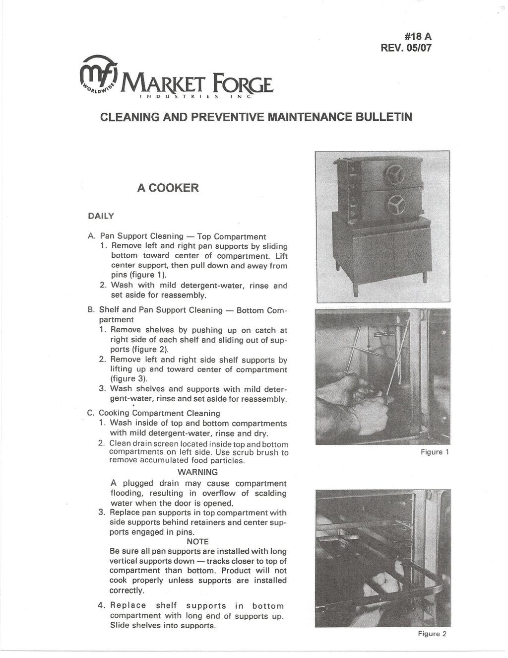
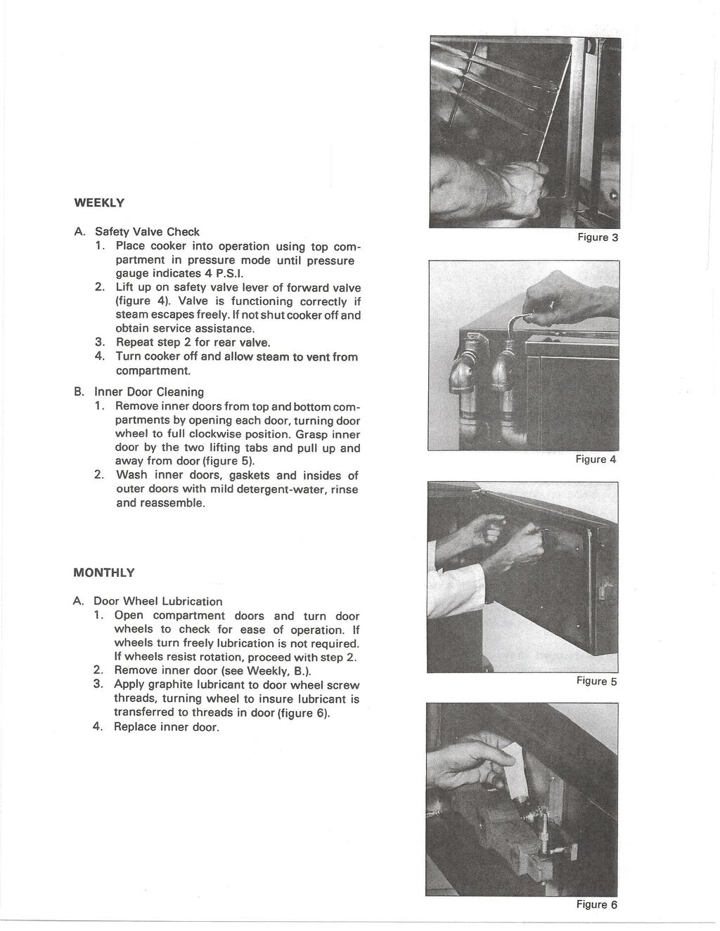
11 MAINTENANCE WARNING: DO NOT HOSE DOWN UNIT AS IT CONTAINS ELECTRICAL COMPONENTS. GENERAL: This section contains both preventive and corrective maintenance information required for the A-PLUS Cooker. Preventive maintenance may be performed by maintenance personnel at the establishment in which the cooker is installed. It is recommended that user personnel never attempt to make repairs or replacements to the equipment without the assistance of authorized service. Assistance in service methods or a current Directory of Authorized Service Agencies may be obtained from Market Forge. PREVENTIVE MAINTENANCE: A good preventive maintenance program begins with the daily cleaning procedure described in the table below. Additional preventive maintenance operations are presented in this section. FREQUENCY DAILY WEEKLY MONTHLY PROCEDURE 1. CLEANING: Remove pan supports, shelves and shelf supports, and thoroughly wash and rinse interior of both cooking compartments. Be sure the drain screen, located inside top compartment, is clear of all food particles. 1. SAFETY VALVE CHECK: With upper compartment in operation in the pressure cooking mode, lift up on level of forward mounted safety valve. Repeat for rear mounted safety valve. Steam should flow freely from outlet port, verifying proper functioning and clearing of accumulated deposits in valves. 2. INNER DOOR CLEANING: Remove inner door from both compartments. Wash inner door and inside of outer door with mild detergent, rinse and reassemble. 1. DOOR WHEEL LUBRICATION: Check door hand wheel rotation for ease of motion. If wheel resists rotation when door is unlatched, lubrication is required. Remove inner door and apply graphite lubrication to screw threads. DRAIN SCREEN CLEANING & REMOVAL: The drain screen inside the top compartment is provided to prevent blockage of the drain line. It must be kept clean at all times by scrubbing daily with a stiff bristle brush. WARNING: A plugged drain may cause compartment flooding, resulting in overflow of scalding water when door is opened. Should the drain screen require removal due to excessive blockage or damage, the truss head screw is loosened and the screen slipped out. The screen must be in position, completely covering the lower drain opening, prior to reuse of the A-PLUS. SAFETY VALVE CHECK: The safety valves are protective devices which automatically relieve excessive pressure (above 8 PSI) in the unlikely event of equipment malfunction. Manual opening of the valves is also possible and should be done once a week to assure valves are clear and mechanically sound Place upper cooker compartment into operation in the pressure mode and allow pressure to build to about 4 PSI. Pull up on safety valve lever for forward-mounted valve (closest to manifold box on left side of cooker). Flow of steam from the valve outlet verifies correct manual valve function and clears exhaust passage. NOTE: Steam is not present at relief valve until steam trap has evacuated all air from the cooker compartment. Presence of adequate steam should be checked (4-5 psi on gauge) before checking valve. Repeat step 2 for rear-mounted valve. INNER DOOR REMOVAL & CLEANING: The door assembly includes an outer door with mounted hand wheel and an inner door with sealing gasket. The inner door parts should be cleaned weekly to ensure proper sealing against compartment opening. 9


, an additional steam condensing circuit is supplied in boilers used with the A")
12 MAINTENANCE With door opened and hand wheel turned to full clockwise position, grasp tabs and lift inner door up and away from door. Wash inner doors, gaskets and inside of outer door with mild detergent, rinse and reassemble. DOOR WHEEL LUBRICATION: The door wheel includes the externally mounted wheel and built-in screw mechanism. Rotation of the door wheel should be checked monthly for ease of motion. If the wheel grinds or is difficult to turn, the screw should be lubricated with graphite followed by rotation of the wheel to transfer lubricant into threads in door. STEAM CONDENSER ADJUSTMENT: The drain and exhaust plumbing assembly for the A Cooker is located inside the cabinet base under the cooking compartments. In addition to the cold water steam condensing system included with the boiler (or direct steam connection plumbing), an additional steam condensing circuit is supplied in boilers used with the A Cooker. This circuit functions automatically at all times when the cooker is operating in the Pressureless mode. ASSEMBLY FOR A SERIES COOKERS DOOR ASSEMBLY INSTRUCTIONS STEP 1: Make sure the handle on the door is turned as far clockwise as possible. (See Figure 1.) Figure 1. STEP 2: Take the inner door (Shipped as shown in Figure 2.) out of cavity. Remove packaging and discard. Figure 2. STEP 3: Line up the outer door pins (marked "A") with the inner door holes (marked "B"). Set the door in place and turn handle counter-clockwise until you bring the inner door to the outer door. (See Figure 3.) Figure 3.
13 MAINTENANCE TO REPLACE A WORN OR DAMAGED DOOR GASKET: Remove the screws from the gasket of the inner door. Slip out the old gasket. Clean the face of the inner door and the gasket plate. Place the new gasket and gasket plate in position and fasten the screws through the assembly as illustrated below. Tighten the screws enough to make a firm seal. It is recommended that a spare gasket be kept on hand in event of an emergency. Replacement gaskets may be obtained for your model by requesting MODEL A DOOR GASKET # Include the serial number of your steam cooker with your order when ordering parts. ILLUSTRATED PARTS LIST ORDERING INFORMATION: Orders for repair parts should be directed to the nearest authorized parts distributor. Contact the factory for a current Market Forge Authorized Parts Distributor List.All orders should contain the Market Forge part number(s), the part description(s), the model and serial numbers. NOTES FOR PAGES 12 THROUGH 17: 11
14 ILLUSTRATED PARTS LIST The Following Parts List is Injunction with the Illustrations on pages 15 Through 17. ITEM PART NO. DESCRIPTION ASSY, WELDMENT, BODY, 2A COOKER ASSY, WELDMENT, BODY, 3A COOKER ASSY, WELDMENT, BODY, 4A COOKER ASSY,STRAINER ASSY, HEADER, STEAM AND EXHAUST 2A COOKER ASSY, HEADER, STEAM AND EXHAUST 3A COOKER ASSY, HEADER, STEAM AND EXHAUST 4A COOKER TRAP, STEAM ASSY, ARM, OPERATING VALVE SPRING, SYNCHRONIZER HANDLE, CONTROL ASSY, HANDLE, LATCH AND BRACKET SPRING, ARM, OPERATING TUBING, PRESSURE GAUGE ADAPTOR 90 O, 3/8 NPT STEAM TRAP NIPPLE 3/4 IPS x 8 LONG (BRASS) 13 NPN KNOB, TIMER (MANUAL (PART OF TIMER) KNOB, TIMER (AUTOMATIC) PLATE, NAME, SERIAL NUMBER PLUG BUTTON 7/8 DIA. HOLE (SEE NOTE #2 ON PAGE 11) NUT, TYPE J 8-32 C SEAL, NSF LABEL ASSY, WELDMENT, BRAKET RELAY, 240V ASSY, ENCLOSURE, COVER TOP, POLISHED ENCLOSURE SUPPORT BOTTOM POLISHED ENCLOSURE SIDE BACK, POLISHED, 2A ENCLOSURE SIDE BACK, POLISHED, 3A ENCLOSURE SIDE BACK, POLISHED, 4A VALVE SAFETY, 3/4, 8 LBS. BRONZE SATIN, CHROME ELBOW, STREET, 90 O, 3/4 IPS BRASS PANEL, SIDE ENCLOSURE 2 COMPARTMENT PANEL, SIDE ENCLOSURE 3 COMPARTMENT ENCLOSURE PANEL, COVER, 4A POLISHED ASSY, DOOR AND HINGE, POLISHED 4A (SEE TAB. DWG ) ASSY, DOOR AND HINGE, POLISHED 3A (SEE TAB. DWG ) ASSY, DOOR AND HINGE, POLISHED 2A (SEE TAB. DWG ) SCREW, TRUSS HD x 3/4 LONG STAINLESS STEEL ASSY, CONTROL PANEL, 2A MANUAL (SEE TAB. DRAWING NO ) ASSY, CONTROL PANEL, 2A AUTO, 120V, 60HZ (SEE TAB. DWG ) 12
15 ILLUSTRATED PARTS LIST ASSY, CONTROL PANEL, 2A AUTO, 240V, 50HZ (SEE TAB. DWG ) ASSY, CONTROL PANEL, 3A MANUAL (SEE TAB. DWG ) ASSY, CONTROL PANEL, AUTO, 120V, 60HZ (SEE TAB. DWG ) ASSY, CONTROL PANEL, AUTO, 240V, 50HZ (SEE TAB. DWG ) ASSY, CONTROL PANEL, 4A MANUAL (SEE TAB. DRAWING NO ) ASSY, CONTROL PANEL, 4A AUTO, 120V, 60HZ (SEE TAB. DWG ) ASSY, CONTROL PANEL, 4A AUTO, 240V, 50HZ (SEE TAB. DWG ) CHANNEL, 2 COMPARTMENT CHANNEL, 3 COMPARTMENT (THIS ITEM IS NOT USED ON 4A MODELS) 30 NPN SCREW, SHEET METAL, TYPE B, SLOT PAN HD., ST/ST, 10 x 1/2 LONG (USE THIS ITEM ON 4A MODELS TO FILL HOLES IN ITEM S 20 AND 21) NUT, STOP, 1/ WASHER, FLAT 1/4 STAINLESS STEEL WASHER, LOCK 1/4 STAINLESS STEEL SCREW, MACH. RD. HD. 1/4-20 x 3/8 LONG CADMIUM PLATED SCREW, PAN HD. TYPE B 1/2 LONG STAINLESS STEEL SCREW, CAP, HEX HD. 3/8-16 x 1 1/8 LONG STAINLESS STEEL WASHER, LOCK 3/8 CADIUM PLATED SCREW, SHOULDER 1/ WASHER LOCK HEL. SP. TYPE #8 NP SCREW RD. HD x 1 1/4 LONG NUT, HEX EYE BOLT WITH NUT ANGL.E EFT, OPERATING ARM SCREW, TRUSS HD x 3/8 LONG ELBOW COMPRESSION 1/8 IPS x 3/16 OD RIVET, POP 1/8 DIA. x LONG LOCTITE SCREWLOCK WASHER, LOCK 1/4 STAINLESS STEEL ASSEMBLY, LATCH SECONDARY WASHER, FLAT 1/4 STAINLESS STEEL SCREW, MACH. HEX. HD. 1/4-20 x 1/2 LONG RELAY, GENERAL PURPOSE 240V RELAY POWER MIDGET SOCKET PLATE, NAME, IDENTIFICATION AUTOMATIC PLATE, NAME, IDENTIFICATION MANUAL SCREW, PAN HD. #6 TYPE A 3/8 LONG (4A ONLY) RIVET, POP, DOMED HD. 1/8 DIZ ASSEMBLY GUIDE BRACKET AND MICRO SWITCH PIN COTTER 1/16 DIA. x 1l LONG STAINLESS STEEL ASSEMBLY, DOOR AND LUBRICATION PROCEDURE 13
16 ILLUSTRATED PARTS LIST SPRING HOLD DOWN, MIDGET RELAY INSULATION, BUZZER BUZZER 120V BUZZER 240V SOLENOID 120V SOLENOID 240V ROD PUSH SOLENOID CLIP, CABLE, PLASTIC (SEE NOT #3 ON PAGE 11) TAPE ELECTRICAL 3/4 WIDE 69 NPN LABEL, RED-WIRING DIA. 4A (MADE FROM ) 69 NPN LABEL, RED-WIRING DIA. 3A (MADE FROM ) 69 NPN LABEL, RED-WIRING DIA. 2A (MADE FROM ) ASSEMBLY KIT CONNECTION AND FUSE BOX (SEE NOTE #1 ION PAGE 11) SCREW TRUSS HD x 3/8 LONG ZINC PLATE WASHER LOCK # WASHER, LOCK, EXTERNAL TOOTH 1/ NUT, HEX, MACH. 1/ SCREW MACH. RD. HD x 7/8 LONG GASKET VALVE BODY 1/8 TH COMPOUND, SEALING, GASKET ELBOW 90 O, 3/4 IPS, BRASS SOCKET, SCREW, RELAY, 240V WIRING DIAGRAM AND SCHEMATIC, 2A AUTO, 50/60HZ WIRING DIAGRAM AND SCHEMATIC, 3A AUTO, 50/60HZ WIRING DIAGRAM AND SCHEMATIC, 4A AUTO, 50/60HZ WIRE LEAD SCHEDULE, 120V AND 240V LABEL, PROLONG GASKET LIFE (NOT SHOWN) SCREW, MACH. PAN HD. #6-32 x 3/8 STAINLESS STEEL (2A AND 3A ONLY) 14
17 ILLUSTRATED PARTS LIST FIGURE 3. MAIN ASSEMBLY, AUTOMATIC AND MANUAL CONTROLS 15
18 ILLUSTRATED PARTS LIST 16
19 ILLUSTRATED PARTS LIST FIGURE 5. CONTROL BOX ASSEMBLY, AUTOMATIC AND MANUAL CONTROLS 17
20 ILLUSTRATED PARTS LIST ITEM FIGURE 6. DOOR ASSEMBLY PART NO. DESCRIPTION ITEM PART NO HAND GRIP PIVOT HINGE DESCRIPTION GASKET SCREWS HANDWHEEL, SPOKED GASKET PLATE OUTER DOOR, POLISHED DOOR GASKET THRUST WASHER INNER DOOR DOOR BUSHING INNER DOOR ASSEMBLY (ITEM S 1-5) ROLL PIN /16-10 x 3/4 HX. HD. BOLT STRONG BACK /32 ID x 3/4 OD FT. WASHER ST/ST CAP SCREW /16 THREADSEAL SUPPORT STUD ASSEMBLY DOOR SPRING RELEASE HX. NUT 3/ DOOR PIVOT BEARING HANDWHEEL BUSHING /16 THK. x 1 OD FLAT WASHER HX. JAM NUT 3/ HINGE - POLISHED DOOR ADJUSTING TOOL HINGE - PAINTED 18
21 ILLUSTRATED PARTS LIST FIGURE 7. HEADER, STEAM AND EXHAUST ASSEMBLY 19
22 ILLUSTRATED PARTS LIST ITEM PART NO. FIGURE 7. HEADER, STEAM AND EXHAUST ASSEMBLY DESCRIPTION QTY. 2 COMPARTMENT QTY. 3 COMPARTMENT QTY. 4 COMPARTMENT ASSEMBLY, VALVE, BRASS TEE, REDUCING, BRASS 3/4 x 1/2 X 1/2 NPT NIPPLE, CLOSE, BRASS 1/2 NPT NIPPLE, HOSE 3/4 NPT MALE x 1 ID, HOSE ZINC PL NIPPLE, BRASS 3/4 NPT x 1 3/4 LG CLAMP, HOSE NIPPLE, CLOSE, BI 3/4 NPT ELBOW, STREET 45 O MI 3/4 NPT Y BRANCH, 45 O MI 3/4 NPT TEE, REWORK ASSEBLY HOSE, TEFLON WITH BRAIDED ST/ST (SEE TAB. DWG. C ) ELBOW, 90 O, BRASS 3/4 NPT NIPPLE, CLOSE BI 3/4 NPT GASKET, VALVE BODY TEE BRASS 1/2 NPT HOSE, 1 ID x 1 1/4 OD X 9 3/8 LG
23 ELECTRICAL INFORMATION FIGURE 8. 2 COMPARTMENT WIRING DIAGRAM 21
24 ELECTRICAL INFORMATION FIGURE 9. 2 COMPARTMENT SCHEMATIC DIAGRAM 22
25 ELECTRICAL INFORMATION FIGURE COMPARTMENT WIRING DIAGRAM 23
26 ELECTRICAL INFORMATION FIGURE COMPARTMENT SCHEMATIC DIAGRAM 24
27 ELECTRICAL INFORMATION FIGURE COMPARTMENT WIRING DIAGRAM 25
28 ELECTRICAL INFORMATION FIGURE COMPARTMENT SCHEMATIC DIAGRAM 26
29
30
OWNER S MANUAL. Form Number: S-6086 REV: A 07/11
 OWNER S MANUAL A-PLUS STEAM COOKER Form Number: S-6086 REV: A 07/11 Printed in U.S.A. 35 Garvey Street Everett MA 02149 Tel: (617) 387-4100 Fax: (617) 387-4456 Outside MA Fax: (800) 227-2659 E-Mail: CUSTSERV@mfii.com
MANUAL A-PLUS STEAM COOKER
 MANUAL A-PLUS STEAM COOKER Form No.: S-2330 11/03 35 Garvey Street Everett MA 02149 Tel: (617) 387-4100 Fax: (617) 387-4456 (800) 227-2659 E-Mail: CUSTSERV@mfii.com Website: mfii.com PARAGRAPH TABLE OF
ST10-2G GAS TWO COMPARTMENT CONVECTION STEAMER WITH TWIN GENERATORS INSTALLATION - OPERATION - MAINTENANCE
 ST10-2G GAS TWO COMPARTMENT CONVECTION STEAMER WITH TWIN GENERATORS INSTALLATION - OPERATION - MAINTENANCE Telephone: (802) 658-6600 Fax: (802) 864-0183 www.marketforge.com PN 14-0275 Rev B (1/17) 2017
ECO-TECH PLUS ELECTRIC CONVECTION STEAMER INSTALLATION - OPERATION - MAINTENANCE ETP-10E MODEL
 ECO-TECH PLUS ELECTRIC CONVECTION STEAMER INSTALLATION - OPERATION - MAINTENANCE MODEL ETP-10E Telephone: (802) 658-6600 Fax: (802)864-0183 www.marketforge.com PN 14-0269 Rev C (1/17) 2017 - Market Forge
SC-6DS,SC-10DS and SC-16DS DIRECT STEAM CONVECTION STEAMER INSTALLATION OPERATION MAINTENANCE
 SC-6DS,SC-10DS and SC-16DS DIRECT STEAM CONVECTION STEAMER INSTALLATION OPERATION MAINTENANCE BLODGETT OVEN COMPANY www.blodgett.com 44 Lakeside Avenue, Burlington, Vermont 05401 USA Telephone: (802) 658-6600
OWNER S MANUAL ELECTRIC STEAM-IT STEAM COOKER, STYLE C MODEL ST-E
 OWNER S MANUAL ELECTRIC STEAM-IT STEAM COOKER, STYLE C MODEL ST-E An Employee Owned Company 35 Garvey Street Everett MA 0249-4403 Form No. S-543D 04/0 Tel: (67) 387-400 Fax: (67) 387-4456 (MA) Toll Free:
3500 SERIES CONVECTION STEAM COOKER PARTS AND SERVICE MANUAL
 3500 SERIES CONVECTION STEAM COOKER PARTS AND SERVICE MANUAL EFFECTIVE JULY 30, 2014 Superseding All Previous Parts Lists. The Company reserves the right to make substitution in the event that items specified
OWNER S MANUAL MODULAR DIRECT CONNECTED TILTING STEAM JACKETED KETTLE
 OWNER S MANUAL MODULAR DIRECT CONNECTED TILTING STEAM JACKETED KETTLE MODELS: MT6 MT6T6 MT10 MT10T10 MT10T6 LFT6 LFT10 LFT10T6 LFT10T10 Form Number: S-2306 REV:C 10/12 Printed in U.S.A. 35 Garvey Street
INSTALLATION & OPERATION MANUAL FOR ELECTRIC COUNTER CONVECTION STEAMERS MODELS VSX3, VSX4 & VSX5
 INSTALLATION & OPERATION MANUAL FOR ELECTRIC COUNTER CONVECTION STEAMERS MODELS VSX3, VSX4 & VSX5 ML'S - 52396, 52397, 52398, & 52399 MODEL VSX3 SHOWN VULCAN-HART COMPANY, P.O. BOX 696, LOUISVILLE, KY
ECO-TECH PLUS GAS CONVECTION STEAMER INSTALLATION - OPERATION - MAINTENANCE MODEL
 ECO-TECH PLUS GAS CONVECTION STEAMER INSTALLATION - OPERATION - MAINTENANCE MODEL ETP-10G Telephone: (802) 658-6600 Fax: (802)864-0183 www.marketforge.com PN 14-0270 Rev C (1/17) 2017 - Market Forge Your
ECOJET EJ-10E & EJ-7E ELECTRIC CONVECTION STEAMER W/TWIN GENERATORS PARTS AND SERVICE MANUAL
 ECOJET EJ-10E & EJ-7E ELECTRIC CONVECTION STEAMER W/TWIN GENERATORS PARTS AND SERVICE MANUAL EFFECTIVE JULY 31, 2014 Superseding All Previous Parts Lists. The Company reserves the right to make substitution
INSTALLATION AND OPERATION MANUAL ELECTRIC TILTING SKILLETS MODELS: ETS - 30 ETS - 40
 INSTALLATION AND OPERATION MANUAL ELECTRIC TILTING SKILLETS MODELS: ETS - 30 ETS - 40 CROWN FOOD SERVICE EQUIPMENT LTD. 70 OAKDALE ROAD, DOWNSVIEW (TORONTO), ONTARIO, CANADA, M3N 1V9 TELEPHONE: (416) 746-2358,
INSTALLATION AND OPERATION MANUAL ELECTRIC COUNTER CONVECTION STEAMER MODELS: SX-3 SX-5
 IMPORTANT FOR FUTURE REFERENCE Please complete this information and retain this manual for the life of the equipment: Model #: Owner s Manual Serial #: Date Purchased: INSTALLATION AND OPERATION MANUAL
BLP-E ELECTRIC FLOOR MODEL BRAISING PAN WITH ELECTRIC POWER TILT INSTALLATION OPERATION MAINTENANCE
 BLP-E ELECTRIC FLOOR MODEL BRAISING PAN WITH ELECTRIC POWER TILT INSTALLATION OPERATION MAINTENANCE BLODGETT OVEN COMPANY www.blodgett.com 44 Lakeside Avenue, Burlington, Vermont 05401 USA Telephone: (802)
OPERATOR S MANUAL Electric Counter Convection Steamer
 IMPORTANT FOR FUTURE REFERENCE Please complete this information and retain this manual for the life of the equipment: Model #: Serial #: Date Purchased: OPERATOR S MANUAL Electric Counter Convection Steamer
INSTALLATION & OPERATION MANUAL
 INSTALLATION & OPERATION MANUAL ROUND ELECTRIC TILTING SKILLET MODEL VECTS16 MODEL VECTS16 ML-114825 VULCAN-HART COMPANY, P.O. BOX 696, LOUISVILLE, KY 40201-0696, TEL. (502) 778-2791 FORM 31035 Rev. A
ALTAIR II CONVECTION STEAM COOKER PARTS AND SERVICE MANUAL
 ALTAIR II CONVECTION STEAM COOKER PARTS AND SERVICE MANUAL EFFECTIVE MAY, 0 Superseding All Previous Parts Lists. The Company reserves the right to make substitution in the event that items specified are
OPERATOR S MANUAL Electric Counter Convection Steamer
 IMPORTANT FOR FUTURE REFERENCE Please complete this information and retain this manual for the life of the equipment: Model #: Serial #: Date Purchased: OPERATOR S MANUAL Electric Counter Convection Steamer
CATALOG OF REPLACEMENT PARTS HSROG SERIES SINGLE RACK OVEN. A product of HOBART CORPORATION 701 S. RIDGE AVENUE TROY, OHIO
 CATALOG OF REPLACEMENT PARTS HSROG SERIES SINGLE RACK OVEN HSROG ML-111148 A product of HOBART CORPORATION 701 S. RIDGE AVENUE TROY, OHIO 45374-0001 FORM 43003 (June 2001) HOT SECTION 26 OVEN TOP SECTION
PS-3E AND PS-6E ELECTRIC CONVECTON STEAMERS PARTS AND SERVICE MANUAL
 PS-3E AND PS-6E ELECTRIC CONVECTON STEAMERS PARTS AND SERVICE MANUAL EFFECTIVE AUGUST 1, 2014 Superseding All Previous Parts Lists. The Company reserves the right to make substitution in the event that
BUILT-IN DISHWASHER INSTALLATION INSTRUCTIONS
 BUILT-IN DISHWASHER INSTALLATION INSTRUCTIONS PLEASE READ COMPLETE INSTRUCTIONS BEFORE YOU BEGIN LEAVE INSTALLATION INSTRUCTIONS AND USER'S GUIDE WITH OWNER ALL ELECTRIC WIRING AND PLUMBING MUST BE DONE
INTEK STEAMER ELECTRIC MODEL XS
 PROJECT NAME: INTEK STEAMER ELECTRIC MODEL XS The Intek XS connectionless countertop steamer unit has a pan capacity of 6 pans (2.5 deep 12 x 20 ) or 4 pans (4 deep 12 x 20 ). Unit must be capable of producing
PCE_YBD60-100_IB_WM_ENG_V2_ indd 1
 PCE_YBD60-100_IB_WM_ENG_V2_150728.indd 1 PCE_YBD60-100_IB_WM_ENG_V2_150728.indd 2 LIMITED WARRANTY 4 SPECIAL FEATURES 5 BUILT-IN SAFETY FEATURES 6 IMPORTANT SAFEGUARDS 7 PARTS AND ACCESSORIES 8 GENERAL
IMAGE V. Parts and Service Manual
 IMAGE 0V Section II Parts and Service Manual (88B) CLARKE TECHNOLOGY Image Operator's Manual Page AUTHORIZED PERSONNEL MAINTENANCE To Access Pump Motor. Remove brush housing from machine. See "Brush Motor
EXPLODED VIEWS & PARTS LISTS
 561 DOOR VIEW Ref. Part No. Description Ref. Part No. Description 1 6200720 Screw, #8-18 x 1/2 PH Truss HD 2 420040 Standard Handle End Cap Replacement Components 4200700 Extended Handle End Cap Replacement
TECHNICAL INSTRUCTIONS
 TECHNICAL INSTRUCTIONS 24-Month Maintenance Kit P/N 58025-06 For BMK2.0LN Boilers Description of Document: This TID provides the procedures to perform recommended 24-Month maintenance on the following
INSTALLATION AND OPERATION MANUAL GAS SKILLETS MODELS:
 INSTALLATION AND OPERATION MANUAL GAS SKILLETS MODELS: ACGS-30 ACGS-40 ACCUTEMP PRODUCTS, INC. 8415 North Clinton Park Dr. Fort Wayne, IN 46825 800 210-5907 Office 260 493-0415 Fax www.accutemp.net PART
Technical Data. Name: ERIKA Automat fully automatic machine to divide and to round dough pieces of the same size
 AUTOMAT MANUAL 1 Technical Data Name: ERIKA Automat fully automatic machine to divide and to round dough pieces of the same size Type Divisions Dough Portions (in ounces) Plate Nos. 3 30 1.0 3.5 #35 4/40A
TECHNICAL INSTRUCTIONS
 TECHNICAL INSTRUCTIONS Benchmark 3.0LN 24-Month Maintenance Kit# 58015-04 This kit applies to units with an Ignitor and a separate gas injector. For units with an Ignitor-Injector (P/N 58023), see Kit
ECO-JET CONVECTION STEAMER W/TWIN GENERATORS INSTALLATION - OPERATION - MAINTENANCE EJ-10E MODELS
 ECO-JET CONVECTION STEAMER W/TWIN GENERATORS INSTALLATION - OPERATION - MAINTENANCE MODELS EJ-10E Telephone: (802) 658-6600 Fax: (802)864-0183 www.marketforge.com PN 14-0274 Rev B (1/17) 2017 - Market
TECHNICAL INSTRUCTIONS
 TECHNICAL INSTRUCTIONS 24-Month Maintenance Kit P/N 58025-04 For BMK3.0LN Boilers Description of Document: This TID provides the procedures to perform recommended 24-Month maintenance on the following
CMA Dishmachines Knott Avenue Garden Grove, CA Undercounter High Temperature Dishwasher. Service Replacement Parts.
 CMA Dishmachines 1700 Knott Avenue Garden Grove, CA 981 Toll Free: 1- (800) 8-617 Fax: 1- (71) 89-11 Service Replacement Parts Undercounter High Temperature Dishwasher Model: UC6e M Machine Serial No.
CROWN SERVICE MANUAL ELECTRIC COUNTERTOP STEAMERS MODELS: PX-3 PX-5
 CROWN SERVICE MANUAL ELECTRIC COUNTERTOP STEAMERS MODELS: PX-3 PX-5 CROWN FOOD SERVICE EQUIPMENT LTD. 70 OAKDALE ROAD, DOWNSVIEW, (TORONTO), ONTARIO, M3N 1V9 TELEPHONE: (416) 746-2358, FAX: (416) 746-8324
A B A B4
 TM TM SERVICE INSTRUCTIONS Thermo-Aire Heater Kits and Air-Heater Assemblies 383808-A4 383808-B4 383880-A4 383880-B4 DESCRIPTION The Thermo-Aire Heater is used in situations where oils of heavier viscosity
TECHNICAL INSTRUCTIONS
 TECHNICAL INSTRUCTIONS 24-Month Maintenance Kit P/N 58015-02 For BMK2.0 (Nozzle Mix) Description of Document: This TID provides the procedures to perform recommended 24-Month maintenance on the following
OWNER S MANUAL MODELS: ELECTRIC COMPACT CONVECTION OVEN. FORM NO.: S-2374 REV: A 02/07 An Employee Owned Company
 OWNER S MANUAL ELECTRIC COMPACT CONVECTION OVEN MODELS: 4200 4292 FORM NO.: S-2374 REV: A 02/07 An Employee Owned Company PRINTED IN U. S. A. 35 Garvey Street Everett MA 02149 Tel: (617) 387-47100 Fax:
Operator s Manual. Stripping Solution Applicator
 Operator s Manual Stripping Solution Applicator Record this Important Information Date of Purchase Purchased From Address City State Zip Phone Contact Serial Number Emergency Contacts Medical Emergency
OWNER S MANUAL CAPELLA STEAMER
 OWNER S MANUAL CAPELLA STEAMER MODELS: CAPELLA - 4 CAPELLA - 8 CAPELLA - 6 CAPELLA - 0 CAPELLA - INSTALLATION OPERATION MAINTENANCE STEAM COOKING GUIDELINES PARTS LISTS PARTS & SERVICE 35 Garvey Street,
Model HC-2. Crathco Whipped Hot Chocolate Dispenser. Table of Contents. Operation and Instruction Manual. for
 Crathco Whipped Hot Chocolate Dispenser Operation and Instruction Manual Table of Contents Introduction...1 Specifications...2 Installation and Start-Up Procedures...2 How to Dispense Hot Chocolate...3
MODEL 6430T, 6460 & 6460T POTATO PEELER
 MODEL 6430T, 6460 & 6460T POTATO PEELER MODEL ML-137602 6430T ML-19630 6460 ML-137604 6460T ML-104562 6460C ML-137606 6460CT 701 S. RIDGE AVENUE TROY, OHIO 45374-0001 FORM 37005 (Apr. 2006) Installation,
ME SERIES ELECTRICALLY OPERATED BOILERS INSTALLATION - OPERATION - MAINTENANCE MODELS
 ME SERIES ELECTRICALLY OPERATED BOILERS INSTALLATION - OPERATION - MAINTENANCE MODELS M24E M36E Telephone: (802) 658-6600 Fax: (802)864-0183 www.marketforge.com PN 14-0309 Rev G (11/17) 2017 - Market Forge
OWNER S MANUAL ALTAIR II STEAMER
 OWNER S MANUAL ALTAIR II STEAMER MODELS: ALTAIR II - ALTAIR II - 8 ALTAIR II - 6 ALTAIR II - 0 ALTAIR II - INSTALLATION OPERATION MAINTENANCE STEAM COOKING GUIDELINES PARTS LISTS PARTS & SERVICE 35 Garvey
COS-101 NON SELF FLUSHING COMBI REPLACEMENT PARTS LIST
 COS-101 NON SELF FLUSHING COMBI REPLACEMENT PARTS LIST EFFECTIVE FEBRUARY 16, 2012 Superseding All Previous Parts Lists. The Company reserves the right to make substitution in the event that items specified
CABINET PARTS For Models: 7GS2SHEXPQ03, 7GS2SHEXPL03 (White) (Stainless VCM) REFRIGERATOR
 (Stainless VCM) REFRIGERATOR") CABINET PARTS REFRIGERATOR 03 07 Litho In U.S.A. (mat) 1 Part No. Rev A CABINET PARTS 1 Literature Parts 2261383 Use & Care Guide 2255955 Service & Wiring Sheet 2261377 Energy Guide 2220407 Modular Icemaker
CABINET PARTS REFRIGERATOR 03 07 Litho In U.S.A. (mat) 1 Part No. Rev A CABINET PARTS 1 Literature Parts 2261383 Use & Care Guide 2255955 Service & Wiring Sheet 2261377 Energy Guide 2220407 Modular Icemaker
INSTALLATION AND OPERATION MANUAL GAS FIRED STEAMER MODEL: GCX-2 GCX-10
 INSTALLATION AND OPERATION MANUAL GAS FIRED STEAMER MODEL: GCX-2 GCX-10 CROWN FOOD SERVICE EQUIPMENT LTD. 70 OAKDALE ROAD, DOWNSVIEW, (TORONTO), ONTARIO, CANADA, M3N 1V9 TELEPHONE: (416) 746-2358, FAX:
EXPLODED VIEWS & PARTS LISTS
 542 DOOR VIEW Ref. Part No. Description Ref. Part No. Description 1 6200720 Screw, #8-18 x 1/2 PH Truss HD 2 420040 Standard Handle End Cap Replacement Components 4200700 Extended Handle End Cap Replacement
Audi-Larm Audible Alarm
 Audi-Larm Audible Alarm MAINTENANCE AND REPAIR TAL 1706 (L) Rev. 7 MSA 2017 Prnt. Spec. 10000005389(I) Mat. 10093084 Doc. 10093084 REPLACEMENT KITS AND PARTS LIST TAL 1706 (L) Rev. 7-10093084 2 Exploded
Altra Series Dampener
 Crestline TM Altra Series Dampener Installation Instructions Heidelberg MO X88-66 10/97 Rev-A GENERAL INFORMATION ATTENTION CRESTLINE ALTRA SERIES TM DAMPENER OWNER! Accel Graphic Systems provides parts
Dirt Dragon. Operator and Parts Manual WOOD FLOOR CLEANING MACHINE
 Dirt Dragon WOOD FLOOR CLEANING MACHINE Operator and Parts Manual 1001 Brown Avenue Toledo, Ohio 43607-0127 Customer Service: 800-441-1934 Fax: 800-942-2007 Technical Service: 877-856-5954 www.basicoatings.com
F-P, F-L, FT-P AND FT-L SERIES 2/3 JACKETED DIRECT STEAM TILTING & STATIONARY KETTLES PARTS AND SERVICE MANUAL
 F-P, F-L, FT-P AND FT-L SERIES 2/3 JACKETED DIRECT STEAM TILTING & STATIONARY KETTLES PARTS AND SERVICE MANUAL EFFECTIVE NOVEMBER 2, 2015 Superseding All Previous Parts Lists. The Company reserves the
Manual / Handbuch Spare parts list / Ersatzteilliste
 Manual / Handbuch Spare parts list / Ersatzteilliste Equipment Imp.-Exp. GmbH Zitterpappelweg 9 D - 22391 Hamburg Tel.: + 49 40 60009468-0 Fax: + 49 40 536 75 01 E - M a i l : i n f o @ w e s c o - n a
OPERATING MANUAL MODEL AIR 1500TM AIR DRYER
 OPERATING MANUAL MODEL AIR 500TM AIR DRYER Puregas, LLC 226-A Commerce St. Tel: 800-52-535 Broomfield, Colorado Fax: 303-657-2205 P/N P0255 REV A, 02/9/4 TABLE OF CONTENTS.0 GENERAL... 3 2.0 SPECIFICATIONS...
MXn RACK OVEN SPARES MANUAL MACHINE NO.FG164
 www.monoequip.com MXn RACK OVEN SPARES MANUAL MACHINE NO.FG164 When ordering spares please quote the machine serial number which can be found on the silver information plate of the machine and on the front
Exploded View - Model J-7020M/J-7040M Miter Cut-off Saw Base
 22 Exploded View - Model J-7020M/J-7040M Miter Cut-off Saw Base Parts List - Model J-7020M/J-7040M Miter Cut-off Saw Base 1 J-5507591 Base, Machine 1 1-1 5512197 Plug, Drain (3/8in, PT) 2 5507592 Screw,
SuperKlean Washdown Products
 February 2012 DURAMIX 8000 INSTALLATION AND MAINTENANCE INSTRUCTIONS **DO NOT THROW AWAY AFTER INSTALLATION** **SAVE AND DISPLAY PROMINENTLY WHERE THIS EQUIPMENT IS USED** WARNING HIGH PRESSURE AND HOT
CABINET PARTS. For Models: ASD2522WRW01, ASD2522WRB01, ASD2522WRS01, ASD2522WRD01 (White) (Black) (Stainless) (Universal Silver)
 (Black) (Stainless) (Universal Silver)") CABINET PARTS REFRIGERATOR 12 09 Litho In U.S.A. (wam)(bay) 1 Part No. Rev. A CABINET PARTS 1 Literature Parts W10237701 Use & Care Guide W10158907 Service & Wiring Sheet W10234042 Energy Guide 628370
CABINET PARTS REFRIGERATOR 12 09 Litho In U.S.A. (wam)(bay) 1 Part No. Rev. A CABINET PARTS 1 Literature Parts W10237701 Use & Care Guide W10158907 Service & Wiring Sheet W10234042 Energy Guide 628370
99105A Series - F Brush Lift Assembly Model :99105A 20" EZ BD Floorkeeper (w/ 2-12 V Batteries) - Series F
 - Series F") 9905A Series - F Brush Lift Assembly Model :9905A 0" EZ BD Floorkeeper (w/ - V Batteries) - Series F Page- 5 7 8 9 5 7 8 0 5 7 8 9 0 5 7 8 9 0 0589 NUT, LOCK W/ LOCTITE 070 RING, RETAINING 0 WASHER, PLAIN
9905A Series - F Brush Lift Assembly Model :9905A 0" EZ BD Floorkeeper (w/ - V Batteries) - Series F Page- 5 7 8 9 5 7 8 0 5 7 8 9 0 5 7 8 9 0 0589 NUT, LOCK W/ LOCTITE 070 RING, RETAINING 0 WASHER, PLAIN
MT 25/40 GALLON SERIES
 MT 25/40 GALLON SERIES MODULAR BASE DIRECT STEAM TILTING KETTLES INSTALLATION - OPERATION - MAINTENANCE MODELS MT-25 MT-40 Telephone: (802) 658-6600 Fax: (802) 864-0183 www.marketforge.com PN 14-0323 Rev
Technical Data TYPE T14 & T14D TEMPERATURE PILOT SPENCE ENGINEERING COMPANY, INC. 150 COLDENHAM ROAD, WALDEN, NY SD 4511A T14 PILOT
 Technical Data SD 4511A SPENCE ENGINEERING COMPANY, INC. 150 COLDENHAM ROAD, WALDEN, NY 12586-2035 TYPE T14 & T14D TEMPERATURE PILOT PRINTED IN U.S.A. SD 4511A/9811 5 13 /16 D 4 7 /8 1 13 /16 T14 PILOT
ASTRO ENVELOPE FEEDER AMC FOR HEIDELBERG PRINTMASTER INSTALLATION AND OPERATING INSTRUCTIONS
 ASTRO ENVELOPE FEEDER AMC-2000-17 FOR HEIDELBERG PRINTMASTER INSTALLATION AND OPERATING INSTRUCTIONS INTRODUCTION Thank you for purchasing the Astro Envelope Feeder. It is fast, efficient, reliable, and
CUTMASTER Strip Cutting Machine
 EASTMAN THE EASTMAN CUTMASTER Strip Cutting Machine WARNING Safety glasses must be worn at all times when operating or servicing this equipment. Instruction Manual & Illustrated Parts List Please read
model NO. LSS GALLON SKID MOUNTED HIGH PRESSURE SPRAYER ASSEMBLY / OPERATION INSTRUCTIONS / PARTS
 000 model NO. LSS- 00 GALLON SKID MOUNTED HIGH PRESSURE SPRAYER ASSEMBLY / OPERATION INSTRUCTIONS / PARTS Part number and descriptions can be obtained from the illustrated parts list section of this manual.
INSTALLATION AND OPERATION MANUAL STEAM COIL BASE CONVECTION STEAMER MODEL SCX-16
 INSTALLATION AND OPERATION MANUAL STEAM COIL BASE CONVECTION STEAMER MODEL SCX-16 CROWN FOOD SERVICE EQUIPMENT LTD. 70 OAKDALE ROAD, DOWNSVIEW, (TORONTO), ONTARIO, CANADA, M3N 1V9 TELEPHONE: (416) 746-2358,
INSTRUCTION MANUAL with Replacement Parts
 INSTRUCTION MANUAL with Replacement Parts MODEL FD500 FOOD WASTE DISPOSERS (INCLUDES MOTOR PARTS) ML-18978 A product of HOBART CORPORATION 701 S. RIDGE AVENUE TROY, OHIO 45374-0001 FORM 11394 Rev. G (10-98)
Repair Parts List REFRIGERATOR MODEL NUMBER GC20B8C3EB. When requesting service or ordering parts, always provide the following information:
 Repair Parts List REFRIGERATOR MODEL NUMBER GC20B8C3EB When requesting service or ordering parts, always provide the following information: - Product Type - Part Number - Model Number - Part Description
Operating Instructions for the BBO-1 and BBO-2 Basket Blasters
 Operating Instructions for the BBO-1 and BBO-2 Basket Blasters 2101 West Cabot Boulevard Langhorne, PA 19047-1893 www.empire-airblast.com Page 2 Model Number: Serial Number: Date of Purchase: Date of Installation:
ICED CAPPUCCINO MACHINE Taylor MODEL: 390
 4.8.6.3 ICED CAPPUCCINO MACHINE Taylor MODEL: 390 LOCATION: Front of House WHEN CLEANED: Daily, Weekly, Monthly, Seasonal TOOLS/SUPPLIES REQUIRED: Salmon Cloth 2 or 3-Compartment Sink Sink Detergent Sanitizer
ES-5050 / ES5050TE Parts Manual
 ES-5050 / ES5050TE Parts Manual Phase 8 American Dryer Corporation 88 Currant Road Fall River MA 02720-4781 USA Telephone: +1 (508) 678-9000 / Fax: +1 (508) 678-9447 e-mail: techsupport@amdry.com www.adclaundry.com
CABINET PARTS For Models: ED5LHEXTD00 (Universal Silver)
") CABINET PARTS REFRIGERATOR 06 07 Litho In U.S.A. (mat) 1 Part No. Rev. A CABINET PARTS 1 Literature Parts 2309541 Use & Care Guide 2311815 Service & Wiring Sheet 2325842 Energy Label 2261037 Instruction
CABINET PARTS REFRIGERATOR 06 07 Litho In U.S.A. (mat) 1 Part No. Rev. A CABINET PARTS 1 Literature Parts 2309541 Use & Care Guide 2311815 Service & Wiring Sheet 2325842 Energy Label 2261037 Instruction
CATALOG OF REPLACEMENT PARTS
 CATALOG OF REPLACEMENT PARTS LXGe SERIES GLASSWASHERS ML-130255 ML-130256 ML-130257 ML-130258 LXGePR (Cold) LXGeR (Hot) A product of HOBART 701 S. RIDGE AVENUE TROY, OHIO 45374-0001 FORM 43304 Rev. A (May
REF. NO Clamp Assembly 8 1 set Gasket (4 per set) S.S. Lock-washer 3/8 x 1/ Brass Impeller 3.
 S.S. Lock-washer 3/8 x 1/ Brass Impeller 3.") 4.4 SUPPLY PUMPAK ASSEMBLY NOTE: This section applies only to systems, which include a supply pumpak. Only the H6, XA, and XC series systems contain a supply pumpak. If your system is a single zone, H6
4.4 SUPPLY PUMPAK ASSEMBLY NOTE: This section applies only to systems, which include a supply pumpak. Only the H6, XA, and XC series systems contain a supply pumpak. If your system is a single zone, H6
CABINET PARTS For Models: ASD2522WRW03, ASD2522WRB03, ASD2522WRS03, ASD2522WRD03 (White) (Black) (Stainless) (Universal Silver)
 (Black) (Stainless) (Universal Silver)") CABINET PARTS REFRIGERATOR 8 10 Litho In U.S.A. (jdc)(bay) 1 Part No. Rev. A CABINET PARTS 1 Literature Parts W10237701 Use & Care Guide W10207987 Service & Wiring Sheet W10307453 Energy Guide 628370 Modular
CABINET PARTS REFRIGERATOR 8 10 Litho In U.S.A. (jdc)(bay) 1 Part No. Rev. A CABINET PARTS 1 Literature Parts W10237701 Use & Care Guide W10207987 Service & Wiring Sheet W10307453 Energy Guide 628370 Modular
I N ST R UC T I ON MODEL 2612 & 2712 SLICERS MODELS 2612 ML ML FORM (12-98) 2612 SLICER
 2612 SLICER") I N ST R UC 2612 SLICER T I ON S MODEL 2612 & 2712 SLICERS MODELS 2612 ML-104829 2712 ML-104822 701 S. RIDGE AVENUE TROY, OHIO 45374-0001 FORM 34141 (12-98) Installation, Operation, and Care of MODEL 2612
I N ST R UC 2612 SLICER T I ON S MODEL 2612 & 2712 SLICERS MODELS 2612 ML-104829 2712 ML-104822 701 S. RIDGE AVENUE TROY, OHIO 45374-0001 FORM 34141 (12-98) Installation, Operation, and Care of MODEL 2612
Installation Instructions. For the 18 Built-In Dishwasher and Front Color Panels
 Installation Instructions For the 18 Built-In Dishwasher and Front Color Panels Printed in USA 154232102 Before You Begin DO NOT INSTALL DISHWASHER UNTIL YOU HAVE READ ALL INSTRUCTIONS. FOR YOUR SAFETY,
CABINET PARTS REFRIGERATOR. For Models: GD2SHAXKQ03, GD2SHAXKT03, GD2SHAXKB03 (White) (Biscuit) (Black) 5 02 Litho In U.S.A. (mek) 1. Part No.
 (Biscuit) (Black) 5 02 Litho In U.S.A. (mek) 1. Part No.") CABINET PARTS REFRIGERATOR 5 02 Litho In U.S.A. (mek) 1 Part No. CABINET PARTS 1 LITERATURE PARTS LIT2220699 Use & Care Guide LIT2220104 Service & Wiring Sheet LIT2220300 Energy Guide LIT2220407 Modular
CABINET PARTS REFRIGERATOR 5 02 Litho In U.S.A. (mek) 1 Part No. CABINET PARTS 1 LITERATURE PARTS LIT2220699 Use & Care Guide LIT2220104 Service & Wiring Sheet LIT2220300 Energy Guide LIT2220407 Modular
WET/DRY VACUUMS PV-12 PV-18 PV-18S PV-18D. Gulper 12P Gulper 18P Gulper 18PS Gulper 18PD OPERATING & MAINTENANCE
 WET/DRY VACUUMS PV-12 PV-18 PV-18S PV-18D Gulper 12P Gulper 18P Gulper 18PS Gulper 18PD INTRODUCTION OPERATING & MAINTENANCE INSTRUCTIONS This operator s book has important information for the use and
Teflon Rotary Drum Pump
 Operating Instructions & Parts Manual 6005 Please read and save these instructions. Read carefully before attempting to assemble, install, operate or maintain the product described. Protect yourself and
WU701 BLOWER/AIR INLET & WATER LEVEL FLOAT
 WU701 BLOWER/AIR INLET & WATER LEVEL FLOAT WU701 BLOWER/AIR INLET & WATER LEVEL FLOAT 2 310217 NO LONGER AVAILABLE (S/P) 3 900882 SWITCH, WATER LEVEL (S/P) 4 900911 FLOAT SWITCH & BRACKET ASSM (S/P) 5
Operator s Manual CAYENNE HEAT N SERVE 4/3 RECTANGULAR RETHERMALIZER ENGLISH
 CAYENNE HEAT N SERVE 4/ RECTANGULAR RETHERMALIZER Item Description Voltage Watts Amps Plug 2050 T4R Countertop without Drain 120 1600 1. 5-15P 2051 TD4R Countertop with Drain 120 1600 1. 5-15P 2 T4R Countertop
INSTALLATION INSTRUCTIONS
 INSTALLATION INSTRUCTIONS BUILT-IN BOTTOM MOUNT REFRIGERATOR/FREEZER DBRTGK72SS-GRILLE KIT (FOR designer SERIES ONLY) VIKING RANGE CORPORATION 111 Front Street Greenwood, Mississippi (MS) 38930 USA (662)
Diva Acoustical Shell
 Owner s Manual Diva Acoustical Shell CONTENTS Important User Information........................... General..................................... Manufacturer................................. Intended Use.................................
FRAME AND CONSOLE PARTS
 FRAME AND CONSOLE PARTS UNDERCOUNTER DISHWASHER 1 3375275 Console (Includes Item 2) 2 3376026 Insert, Console 3 3376029 Switch, 5 Pushbutton 4 3369529 Follower, Cam 5 3373626 Timer 6 3369415 Cam 7 304231
HORIZONTAL AGITATOR ASSEMBLY
 HORIZONTAL AGITATOR ASSEMBLY (PATENT NO. US 6,193,409 B1) Installation Manual Part No. 9828450 Effective April 5, 2000 HORIZONTAL AGITATOR ASSEMBLY (PATENT NO. US 6,193,409 B1) Installation and Operation
OWNER S MANUAL SIRIUS II STEAMER
 OWNER S MANUAL SIRIUS II STEAMER MODELS: SIRIUS II - 4 SIRIUS II - 8 SIRIUS II - 6 SIRIUS II - 0 SIRIUS II - INSTALLATION OPERATION MAINTENANCE STEAM COOKING GUIDELINES PARTS LISTS PARTS & SERVICE 35 Garvey
TECHNICAL DATA. Wet 26a. February 22, 2009
 February 22, 2009 Wet 26a 1. DESCRIPTION The Viking Alarm Check Valve serves as a check valve by trapping pressurized water above the clapper and preventing reverse flow from sprinkler piping. The valve
Owner s Manual. Keep with machine for reference PKC24 INSTALLATION & OPERATION REV Perlick Corporation 8300 W Good Hope Rd Milwaukee, WI 53223
 Owner s Manual Keep with machine for reference PKC24 INSTALLATION & OPERATION REV.11.09 Perlick Corporation 8300 W Good Hope Rd Milwaukee, WI 53223 800-558- 5592 FAX 414-353- 7069 perlick.com TABLE OF
Parts and Service Manual
 Section II Parts and Service Manual (70241A) CLARKE TECHNOLOGY Operator's Manual - MINI MAX Page -29- Frame and Front Cover Assembly Drawing 2/01 Page -30- CLARKE TECHNOLOGY Operator's Manual -MINI MAX
CABINET PARTS For Models: ASD2522WRS07 (Stainless)
") CABINET PARTS REFRIGERATOR 9 11 Litho In U.S.A. (wam) (psw) 1 Part No. Rev. A CABINET PARTS 1 Literature Parts W10321484 Use & Care Guide W10275776 Service & Wiring Sheet W10234042 Energy Guide 628370
CABINET PARTS REFRIGERATOR 9 11 Litho In U.S.A. (wam) (psw) 1 Part No. Rev. A CABINET PARTS 1 Literature Parts W10321484 Use & Care Guide W10275776 Service & Wiring Sheet W10234042 Energy Guide 628370
INSTALLATION, OPERATION, SERVICE & PARTS SUPPLEMENT for
 T-333 Manual INSTALLATION, OPERATION, SERVICE & PARTS SUPPLEMENT for Rooftop Energy Storage Systems (ESS) AIR COOLING UNIT 77-62186-00 THRU -04 & 77-62203-00 T-333 REV. 03/2012 2012 Mobile Climate Control
Front Roller (2) Screw Roller (Rear) (2) Screw Clip, Grille Screw Shim
 Screw Roller (Rear) (2) Screw Clip, Grille Screw Shim") 2 2174748 Front Roller (2) 3 489456 Screw 4 981122 Roller (Rear) (2) 5 489427 Screw 6 2155013 Clip, Grille 7 489478 Screw 9 2156056 Shim 12 2196046 Hinge Top (2) 13 2196048 Shim, Hinge Top 14 489284 Screw
2 2174748 Front Roller (2) 3 489456 Screw 4 981122 Roller (Rear) (2) 5 489427 Screw 6 2155013 Clip, Grille 7 489478 Screw 9 2156056 Shim 12 2196046 Hinge Top (2) 13 2196048 Shim, Hinge Top 14 489284 Screw
Page 1 of 18. Part# /5/2013
 Part# 1002655-06 8/5/2013 This manual contains important information concerning the installation and operation of the gun washers listed above. Read manual thoroughly and keep for future reference INSTRUCTIONS
WHIRLPOOL REFRIGERADOR GS2SHGXLQ01
 CABINET, LITERATURE 1 CABINET, LITERATURE 1 LIT2220425 LITERATURE PARTS (Energy Label) 1 LIT2220699 LITERATURE PARTS (Owner`s Manual) 1 LIT2255381 LITERATURE PARTS (Service & Wiring Sheet) 1 LIT628370
Series 47 and 247 Mechanical Water Feeders. Series 47-2 and Combination Mechanical Water Feeder/Low Water Cut-Off ! WARNING
 Series 47 and 247 Mechanical Water Feeders McDonnell & Miller Installation & Maintenance Instructions MM-316(C) Series 47-2 and 247-2 Combination Mechanical Water Feeder/Low Water Cut-Off Series 47 Water
DISHWASHER. Models DW2432 and DW2432SS. Installation Manual. Write Serial Number (on inner door of unit) here:
 here:") DISHWASHER Models DW2432 and DW2432SS Installation Manual Write Serial Number (on inner door of unit) here: Felix Storch, Inc. Summit Appliance Division 770 Garrison Avenue Bronx, New York 10474 www.summitappliance.com
DISHWASHER Models DW2432 and DW2432SS Installation Manual Write Serial Number (on inner door of unit) here: Felix Storch, Inc. Summit Appliance Division 770 Garrison Avenue Bronx, New York 10474 www.summitappliance.com
ADG-531HS Hot Surface Ignition
 ADG-531HS Hot Surface Ignition Parts Manual 1998 American Dryer Corporation 88 Currant Road Fall River, MA 02720-4781 Telephone: (508) 678-9010 / Fax: (508) 678-9447 E-mail: techsupport@amdry.com 120997JEV/abe
Specifications 3. Bladder 5. Chimney 12. Air Supply 12. Anti-Rollout Device and Ash Auger Tube 14. Timer 15
 TABLE OF CONTENTS Page No. Specifications 3 Bladder 5 Fire Door 7 Chimney 12 Air Supply 12 Anti-Rollout Device and Ash Auger Tube 14 Timer 15 Supply Line and Return Line Threaded Connectors 15 Low Water
CABINET PARTS For Models: ED25UEXHW01, ED25UEXHT01 (White) (Biscuit)
 (Biscuit)") CABINET PARTS REFRIGERATOR 9 00 Litho In U.S.A. (dmz) 1 Part No. CABINET PARTS 1 LIT2205958 Use & Care Guide LIT2204338 Service & Wiring Sheet LIT2211832 Energy Guide LIT628370 Modular Icemaker Service
CABINET PARTS REFRIGERATOR 9 00 Litho In U.S.A. (dmz) 1 Part No. CABINET PARTS 1 LIT2205958 Use & Care Guide LIT2204338 Service & Wiring Sheet LIT2211832 Energy Guide LIT628370 Modular Icemaker Service
Disposal Unit (BKSDU) Burger King Shortening. Operation, Service & Parts Manual BURGER KING BKSDU
 Burger King Shortening. Operation, Service & Parts Manual BURGER KING BKSDU") BURGER KING BKSDU Burger King Shortening Disposal Unit (BKSDU) Operation, Service & Parts Manual Frymaster, a member of the Commercial Food Equipment Service Association, recommends using CFESA Certified
BURGER KING BKSDU Burger King Shortening Disposal Unit (BKSDU) Operation, Service & Parts Manual Frymaster, a member of the Commercial Food Equipment Service Association, recommends using CFESA Certified
UNIVERSAL 750 PRE-MIX DISPENSER
 Anoka, MN. 0 - Telephone -00--00 Facsimile -00--0 MODEL NO. xxx xxx Universal 0 of Control Code A Manual Part No. 00 -- Revised: -- ªIMI Cornelius Co., - Anoka, MN. 0 - Telephone -00--00 Facsimile -00--0
EVOLUTION FOOD STEAMER INSTRUCTION MANUAL
 EVOLUTION FOOD STEAMER INSTRUCTION MANUAL TABLE OF CONTENTS Safety Instructions...4 Parts Description...6 Operating Instructions...7 Cleaning & Maintenance...9 Vegetable Steaming Guide...10 Fish & Meats