Name : Roll no. : Division : Date of commencement : Date of completion :
|
|
|
- Julianna Johnson
- 5 years ago
- Views:
Transcription
1 This is to certify that the dissertation work done by in partial fulfillment of the requirement for the award of the Engineering Training in P.T.P.S, (H.P.G.C.L), Panipat has carried out weeks training under our supervision and guidance. Name : Roll no. : Division : Date of commencement : Date of completion : Mr. has worked under my supervision during above training period. I have read this report. It meets our expectation and accurately reflects work done by him. ( ) ( ) Executive Engineer Assistant Executive Engineer 1
2 ACKNOWLEDGEMENT The present report would not have been possible with out the help, I have received from various quarters. I shall be failing in my duty if don t acknowledge the help and guidance from these sources. I extend my special thanks to Er. Himanshu Gupta XEN Training division and Er. for their benevolent guidance and kind cooperation through out my training and for completing this project report. I also convey my special thanks to staff members. This guidance has helped me a lot in power plant familiarizations and understanding various plant processes. Last but not least, I am thankful to all for their sincere effort during placement. 2
3 INDEX S.NO. Contents 1. Acknowledgement 2. Introduction/Functional of P.T.P.S 3. Familiarization with plant 4. Steam Turbine Specification 5. Valves 6. Rotor Coupling and Bearings 6. Turbine Oil System 7. Condenser 9. Electrostatic Precipitator 10 ID FANS, FD FANS, PA FANS 11. Generator Transformer Specification 12. Station Transformer Specification 13 Unit Auxiliary Transformer Specification 3
4 INTRODUCTION Panipat Thermal Power Station is situated at a distance of about 12 km. from Panipat. It is on Panipat- Jind Road near village Assand. This plant has been constructed in five stages as given below: Stage 1 : Unit -1 Unit -2 Stage 2 : Unit -3 Unit -4 Stage 3 : Unit -5 Stage 4 : Unit -6 Stage 5 : Unit -7 Unit -8 Total generation capacity M.W. 110 M.W. 110 M.W. 110 M.W. 210 M.W. 210 M.W. 250 M.W. 250 M.W M.W. I was assigned training in Panipat Thermal Power Station. I took training about Turbine & its auxiliaries, Water circulation system, & Hydrogen cooling system, Oil system, Condenser and Regenerative system. 4
5 FUNCTIONAL DESCRIPTION The Thermal Power Station burns fuel & uses the resultant to make the steam, which derives the turbo generator. The Fuel i.e. coal is burnt in pulverized from. The pressure energy of the steam produce is converted into mechanical energy with the help of turbine. The mechanical energy is fed to the generator where the magnet rotate inside a set of stator winding & thus electricity is produced in India 65% of total power is generated by thermal power stations. To understand the working of the Thermal Power Station plant, we can divide the whole process into following parts. Steam Water High Pressure Turbine Low Pressure Turbine Generator Air Boiler Fuel Condenser Feed water heater Feed pump 2 Feed pump 1 5
6 THREE MAJOR INPUTS TO POWER STATION 1) Water : Water has been taken from near by Yamuna Canal. This water is lifted by raw water pumps and is sent to clarifier to remove turbidity of water. The clear water is sent to water treatment plant, cooling water system and service water system. The water is de-mineralized (DM) by water treatment plant. The DM water is stored in condensate storage tanks from where it is used in boiler. 2) Fuel Oil : The fuel oil used is of two types: (a) Low sulphur high stock oil (LSHS) (b) High speed diesel oil (HSD) The high speed diesel oil reaches the power station through the lorry tankers. The oil is stored in large tanks for the future use in the boiler. Heavy oil is stored in storage tanks in oil storage yard and is conveyed to the front through a set of pumps and strainers. The whole length of piping from the boiler front in stream traced to maintain the temperature and hence its fluidity so that it can freely flow in the pipelines. 3) COAL : 6
7 The coal reaches the plant in the railways wagons. The unloading of coal is done mechanically by tilting the wagons by tippler. The coal is sent to the coal storage yard through the conveyor belts. The crushed coal from store is sent to the mill bunkers through conveyor belts. The air which takes away the coal dust passes upward into the classifier where the direction of flow is changed abruptly. This causes the coarse particle in the air coal stream to finer coal dust along with the primary air leaves the classifier onto the coal transport piping from where it goes to nozzle. Pulverized coal obtained from coal mill can not be burnt directly. 7
8 FAMILARIZATION WITH PLANT BOILER: Boiler is a device used for producing steam. There are two types of boilers: a) Fire tube boiler b) Water tube boiler Here, boiler used is of water tube type. In the boiler, heat energy transfer takes place through tube walls and drum. The gases lose their heat to water in the boiler or superheated. The escape heat is used to heat the water through economizer. ID and FD fans are used to produce artificial draught. The fuel oil is used to ignite the boiler and pulverized coal is lifted from the coal mills by PA fans. TURBINE & GENERATOR( TG): Turbine is form of heat engine in which available heat energy in the form of steam is converted into kinetic energy to rotate the turbine by steam expansion in suitable shaped nozzles In Thermal Power Station there are reaction turbines. The turbine consists of three stages: high pressure, intermediate pressure and low pressure. Steam enters the turbine at 350 o C with maximum allowable temp. of 545 o C. Cold reheat steam goes to boiler, reheated at 540 o C, then fed to medium pressure parts of the turbine. Then, after cooling it goes to hot well. 8
9 The shaft is coupled with generator. The generator converts the kinetic energy of the rotating shaft to electric energy. Field windings are excited by D.C. power using exciter. Shaft of generator rotates at 3000 rpm speed. CONDENSER: In condenser, the water passes through various tunes and steam passes through a chamber containing a large number of water tubes (about 20000). The steam gets converted into water droplets, when steam comes in contact with water tubes. The condensate is used again in boiler as it is dematerialized water and 5-6 heats the water, which was in tubes, during the process of condensation. This water is sent to cooling tower. 9

10 COOLING TOWER: It is a structure of height 110m designed to cool the water by natural draught. The cross sectional area is less at the center just to create low pressure so that the air can lift up due to natural draught and can carry heat from spherical drops. The upper portion is also diverging for increasing the efficiency of cooling tower. Hence it is named as natural draught cooling tower. 10
11 ELECTROSTATIC PRECIPITATIOR: It is an electronic device, which removes the ash particles from the smoke through furnace of boiler. It helps in prevention of air pollution. It works on the principle that a charged particle is attracted towards opposite charge. When the fly ash comes between the opposites charged plated it gets charged and is attracted towards the plates and then collected from the plates by the discharging particles. ASH HANDLING PLANT: Ash is not discharged as such to pollute the land, air and water, but slurry of ash is made in ash handling plant and this slurry is dumped in the wasteland, kept for the purpose. SWITCH YARD: Switchyard is the area, which feed the grid supply to the station transformer and fees the grid by the power generator by the unit. The power supply control is administrated here and the units consumed and supplies are recorded in the control room. The connections of 220KV BUS to the station transformer is done by using the isolated and gas filled circuit breakers. ELECTRICITY FROM COAL: Electric power generation takes place in the following steps: 11
12 1. Coal to steam 2. Steam to mechanical power 3. Switching and transmission COAL TO STEAM: The boiler burns pulverized coal at rates up to 200 tons per hour. From the coal store, fuel is carried on a conveyor belt and discharged by means of a coal tipper into the bunker. It then falls through a weighed into the coalpulverizing mill where it is ground to a powder as fine as flour. Air is drawn from the top of the boiler house by the forced draught fan and passed through the air preheaters to the hot air duct. From here some of the air passes directly to the burners and the remainder is taken through the primary air fan to the pulverizing mill, where it is mixed with the powdered coal, blowing it along pipes to the burners of the furnace. Here it mixes with the rest of the air and burns with great heat. The boiler consists of a large number of tubes and the heat produced raises the temp. of the water circulating in them to create steam, which passes to the steam drum at very high pressure. The steam is then heated further in the super heater and fed through outlet valve to the high pr. cylinder of the steam turbine. 12
13 When the steam has been through the first cylinder (high pr.) of the turbine, it is returned to the repeater of the boiler and reheated before being passed through the other cylinders(intermediate and low pr.) of the turbine.from the turbine the steam passes into a condenser to be turned back into water condensate. This is pumped through feed heaters where it may be heated to about 250 o C to the economizer where the temp. is raised sufficiently for the condensate to be returned to the lower half of the steam drum of the boiler. The flue gases leaving the boiler are used to reheat the condensate in the economizer and then pass through the air pre-heaters to the electro-static precipitator. Finally they are drawn by the induced draught fan into the main flue and to the chimney. STEAM TO MECHANICAL POWER: From the boiler, a steam pipe conveys steam to the turbine through a stop valve and through control valves that automatically regulate the supply of steam of the turbine, Stop valve and control valves are located in a steam chest and a governor, driven from the main turbine shaft, operates the control valves to regulate the amount of steam used. 13
14 Steam from the control valves enters the high pr. cylinder of the turbine, where it passes through a ring of stationary blades fixed to the cylinder wall. These act as nozzles and direct the steam mounted on a disc secured to the turbine shaft. This second ring turns the shaft as a result of the force of the steam. The stationary and moving blades together constitute a stage of the turbine and in practice many stages are necessary. The steam passes through each stage in turn until it reaches the end of the high pr. cylinder and in its passage some of its heat energy is charged into mechanical energy. The steam leaving the high pr. cylinder goes back to the boiler for reheating and is returned to the intermediate pr. cylinder. Here it passes through another series of stationary and moving blades. Finally, the steam is taken to the low pr. cylinder each of which it enters at the center flowing outwards in opposite directions through the rows of turbine blades- an arrangement known as double flow-to the extremities of the cylinder. As the steam gives up its heat energy to drive the turbine, its temp. falls and it expands. The turbine shaft rotates at 3000 rpm at 50 Hz. The turbine shaft drives the generator to generate alternating current. When as much energy as possible has been extracted from the steam it is exhausted directly to the condenser. This runs the length of the low pr. part of the turbine and may be beneath or on either side of it. From the condenser, the condensate is pumped through low pr. feed 14
15 heaters by the extraction pump, after which its pr. is raised to boiler pr. by the boiler feed pump. It passed through further feed heaters to the economizer and the boiler for recon version into steam. SWITCHING AND TRANSMISSION: The electricity is usually produced in the stator windings of the large modern generators at about 25,000 volts and is fed through terminal connections to one side of a generator transformer that steps up the voltage , or volts. From here conductors carry it to a series of three switches comprising an isolator, a circuit breaker and another isolator. The circuit breaker, which is a heavy-duty switch capable of operating in a fraction of a second, is used to switch off the current flowing to the transmission lines. Once the current has been interrupted the isolators can be opened. These isolate the circuit breaker from all outside electrical sources. From the circuit breaker the current is taken to the bus bars-conductors, which run the length of the switching compound and then to another circuit breaker with its associated isolates before feeding to the grid. Three wires are used in a three-phase system for large power transmission. The center of the power station is the control room. Here engineers monitor the output of 15
16 electricity, supervising and controlling the operation of the generating plant and high voltage switch gear and directing power to the grid system as required. 16
17 STEAM TURBINE Steam Turbines The steam turbine is a prime mover that converts the stored mechanical energy in steam into rotational mechanical energy. A turbine pair consists of a ring of fixed blade and a ring of moving blades. The blades are so designed that the steam glides overt eh blade surface without striking it. As the steam floes over the covered surface of blade, it exerts a pressure on the blade along its whole length owing to its centrifugal force. The motive force on the blade will be the resultant of the centrifugal pressures on the blade length plus the effect of change of the steam as it flows over the blade. Specification: Type 3 Cylinder Mixed Flow Tandem Coupled. Make BHEL. Capacity 250MW Speed 3000 rpm Stages Nos.(HP, IP, LP) Inlet Steam Pressure 150 Kg/cm 2. Inlet Steam Temperature 535 o C. Overall Length m. Overall Width 10.5m. General Design Features 17

18 The turbine is of tandem compound design with separate High Pressure (HP), Intermediate Pressure (IP) and Low Pressure (LP) cylinders. The HP turbine is of Single Flow type while IP and LP turbines are of Double Flow type. The turbine is condensing type with single reheat. It is basically engineered on reaction principle with throttle governing. The stages are arranged in HP, IP and LP turbines driving alternating current full capacity turbo generator. The readily designed HP, IP and LP turbines are combined and sized to required power output, steam parameters and cycle configuration to give most economical turbine set. The design and constructional features have proved their reliability in service and ensure trouble free operation over long operating periods and at the same time ensuring high thermal efficiencies. 18
19 Barrel type High Pressure (HP) Turbine The outer casing of the HP turbine is of barrel type construction without any massive horizontal flange. This unique construction permits rapid startup from any thermal state and high rates of load changes of the turbo set. The steam and metal temperature matching requirements are also less stringent as there is no asymmetry of mass distribution in traverse or longitudinal planes. The barrel type outer casing does not cause any problems during over hauls and capital maintenance as the assemble and disassembly of the turbine can be done in a relatively short time as compared to the conventional design. The HP turbine is of single flow type with 25 reaction stages. Inlet Temperature 535 o C. Outlet Temperature 343 o C. Inlet pressure 150 Kg/cm 2. Outlet Pressure 49 Kg/cm 2. Intermediate Pressure (IP) Turbine The IP turbine is double flow type with horizontal split, inner casing being kinematically supported within the outer casing. It has 20 reaction stages. IP inner and outer casings as well as LP inner casing are suspended from top halves to totally eliminate the effect of TG centerline with the heating of the flanges. Although the casings are of horizontal split design yet these do not impose any constraints in startup timings and rapid load fluctuations. Inlet Temperature 535 o C. 19
20 Outlet Temperature 340 o C. Inlet pressure 37 Kg/cm 2. Outlet Pressure 7 Kg/cm 2. 20
21 Low Pressure (LP) Turbine LP turbine is also double flow type with exhaust area optimally selected for the expected vacuum conditions. It has 8 reaction stages per flow. Special design measures have been adopted to remove the moisture from the last stages by reducing the thickness of water film on the guide blades. The axial clearances between the guide blades and the moving blades have been so chosen so as to reduce the droplet sizes and attendant erosion of leading edges. Lowpressure extraction has been optimized not only from thermodynamic considerations but to effectively drain out moisture also. The casing of LP turbine is connected with IP cylinders by two crosses around pipe, one on either side of the machine and level with the floor. The horizontally split, fabricated LP casing is comprised of three shells. The bearing pedestals are mounted on the foundation. Freestanding blades have been envisaged. The blades are designed to operate in the speed range corresponding to 47.5 Hz to 51.5 Hz grid frequency. Inlet Temperature 360 o C. Outlet Temperature 45 o C. Inlet pressure 7 Kg/cm 2. Outlet Pressure 0.85 Kg/cm 2. 21
22 DIFFERENT VALVES HP turbine is fed from 2 combined emergency stop and control valves. Each combined valves consists of an emergency stop valve and control valve fitted in a common body with the spindles at right angles and in the same plane. The valves are placed on the mezzanine floor in front of the turbine. IP turbine is also fed from 2-combined reheat stop and control valves, which are mounted in the same way as the HP valves. Combined Main Stop Valve and Control Valve: The main stop valves rapidly interrupt the supply of the steam to the turbine after being triggered by monitors should a dangerous conditions arises therefore they have been designed for high-speed closing and maximum reliability. The control valve on the other hand regulates the flow of steam to the turbine according to the prevailing load. One stop valve and one control valve a share a common body in which steam is perpendicular to each other and is placed in front of the turbine. Combined Reheat Stop Valve and Control Valve Reheat stop valves are protective devices triggered by monitors in the event of dangerous conditions to interrupt the flow of steam to the reheat system. The reheat control valves are only operative in the lower range. Above this range, they remain fully open in order to avoid throttling losses. 22

23 Rotor Coupling and Bearings The rotating elements consisting of three mono block rotors of HP, IP and LP turbines coupled together solidly by means of internally forged flanges thus in effect forming a single shaft system. The critical speed of the HP and IP rotors are designed to run above the normal rated speed. Each rotor is subjected to 20% over speed test. The Hp rotor is carried on tow bearings, a simple journal and thrust bearing at the other end directly adjacent to the coupling of the IP rotor. All the bearings are independently supported on separate bearing pedestals. This arrangement ensures maintenance of rotor alignment under all operating conditions. The coupled rotors are located relative to the stationary components by the thrust bearing. 23
24 Bearing and Rotor Coupling Turning Gear High speed hydraulic turning gear is envisaged to ensure uniform and rapid heating and cooling of the casings during startup and trip out respectively. The turning gear is located on IP coupling flanges. As there is no mechanical contact between the hydraulic turning gear and the shaft the likelihood of a break down is far less than the mechanical types employing disengaged gears, interlocks and checking devices. Governing System: The turbine is equipped with Electro Hydraulic governing system backed up with the hydro mechanical system ensuring stable operation under any grid fluctuations and load throw off conditions. Electro Hydraulic Governing System: It is there to facilitate the operation of the turbo set in an inter-connected grid system. The electrical measuring and processing of signals offer the advantages such as flexibility, dynamic stability and simple representation of complicated functional relationship. The processed electrical signal is introduced at a suitable point in the hydraulic circuit through an Electro Hydraulic converter. The hydraulic control provides the advantage of continuous control of large positioning forces for control valves. 24
25 The Electro Hydraulic system has a number of advantages not the least, of which is its high accuracy, high operation speed and sensitivity. It permits governed run up to the rated speed and allows only a small value of the temporary speed deviation during a sudden loss of load. The linear power output/frequency characteristic can be adjusted between closer limits even while the machine is in operation. Turbine Oil System Mineral oil with additives (for increasing the resistance to corrosion and aging) is used as a fluid for actuating the governing system, lubrication of bearings and seal oil to generator seals. During normal operation the main oil pump supplies oil at pressure 8 bar approx. to the lubrication seal oil system and governing system. The oil system fulfills the following functions: Lubricating and cooling the bearings. Driving the hydraulic turning gear during interruption operation, on startup and shutdown. Jacking up the shaft at low speed. Under normal conditions, the MOP (Main Oil Pump) situated in the front bearing pedestal and coupled directly to the turbine shaft, which draws oil from the main oil tank and supplies it to the pressure oil system. The suction of the main oil is aided by to injectors. The injector produces pressure at the suction connection to the MOP. This guarantees that the MOP takes over the supply of oil and cavitations that could occur due to greater suction heads 25
26 and avoided. The amount of oil required is extracted from the pressure oil circuit and is adjusted by throttles. The oil for turning gear is also extracted from the pressure oil system. Oil is admitted to the nozzles by opening the shut off valve. Cooled oil from the oil cooler is reduced to the lubricating oil pressure in the throttle. During turning gear operation and startup and run-down operation, one of the 3- Φ AOP (Auxiliary Oil Pump) supplies the pressure oil system and takes over the function of MOP when it is not in operation during turbine running too slow. The submersible AOP is situated on the main oil tank and draws in oil directly. Check-Valves behind the AOP prevents oil from flowing back via pumps that are not in operation (i.e. MOP). When MOP and AOP fails, the lubrication oil supply is maintained by Emergency Oil Pump. The pump supplies oil directly to the lubrication oil line, by passing oil coolers and thus prevents damage to the bearings shells. The AOP and EOP (Emergency Oil Pump) are automatically started control as soon as the pressure switch limit has been reach. The function of pressure switches arranged in the lubricating oil circuit is to operate the main trip valve when the lubricating oil pressure drops below a said value. The lubricating oil the bearing is returned to the main oil tank via a header. A loop in the return oil piping behind the seal oil reverse tank prevents H 2 gas reaching the main oil tank when there is any disturbance. Oil for the 26
27 Combined Journal and Thrust Bearing is passed through duplex oil filter, for cleaning during operation. Oil supply during Normal Operation: During the normal operation the main oil pump supplies oil to the lubrication, seal oil system and governing system. Oil supply during Startup and Shutdown: During the startup and shutdown 2 auxiliary oil pumps meet the oil requirement of the TG set. They draw oil directly from the oil tank and discharged it into the pressure oil line and continue in operation till the main oil pump takes over the oil supply. A pressure switch in the pressure oil line gives an indication for switching off the auxiliary oil pump. During the shutdown another pressure switch automatically switches on the auxiliary oil pump. Oil Supply during Disturbances: When the pressure in the pressure oil line falls below a set point pressure switches automatically start the auxiliary oil pumps. The setting of pressure switches is arranged in stages so that on fall in oil pressure firstly one auxiliary oil pump is started and the second pump is stated only when the first pump fails to establish necessary oil pressure in the pressure oil line. In case main and auxiliary oil pumps cease to operate simultaneously a pressure switch in the lubrication oil line starts D.C. emergency oil pump. 27
28 Oil Strainer and Vapour Exhauster: The basket type oil strainer is of stainless steel wire mesh of 0.25mm and is mounted in the tank. The whole tank is made airtight, this produces vacuum in the pump when MOP or AOP draws oil from main oil tank. Oil vapour exhauster produces a slight negative pressure in the tank, in the return drain line and in the spaces in the bearing pedestal so those oil vapours are drawn out. Oil Level Indicator: The main oil tank has a direct reading fluid level indicator and a fluid limit switch. This permits signal to be transmitted to UCB when maximum and minimum levels have been reached. Extra tank volume is proved between the normal operating level and the tank cover to accept oil from the entire oil supply system when the turbine is shutdown. Specification of Lubricating Oil Motor: Make Kirloskar Power 1.1KW Voltage 415V Current 4.85A Speed 1410rpm 28
29 Type of Oil Pumps: 1. Main Oil Pump (MOP): The MOP is situated in the front bearing pedestal and supplies the entire turbine with oil i.e. used for bearing lubrication, cooling the shaft journal and thrust bearing. It is driven by the turbine and develops the rated discharge pressure at 90-95% rated speed. The main pump is sized tot eh meet the normal requirements of Lubrication, Seal Oil and Governing System. 2. Auxiliary Oil Pump (AOP): It supplies the oil requirements of the turbo set during start-ups and shutdowns. The oil pump can either be switched on manually or automatically through pressure switches, which operate when the oil pressure drops to approximately 60% of the normal value. The setting of the pressure switches is staggered so that one pump comes into operation before the other one with second one remaining in reserve. The pump continues to remain available for emergency service through the automatic control system. It is stopped after the turbo generator set has come to full speed and main oil pump has taken over. 3. D.C. Emergency Oil Pump (EOP): It is standby pump, which can be started manually or automatically through pressure switch when the tube oil pressure drops to 50% of the normal value. This happens only when 29
30 main and auxiliary pumps fail to operate or there is a break down in the electricity supply system to the pumps. This pump should therefore be fed from station batteries. It has to be in operation and cater to the need of bearing lubrication and cooling of journals. 4. Jacking Oil Pump (JOP): When the set is stationary, the shafts come into metallic contact with the bottom bearing lining. The normal bearing oil supply at low speeds is unable to penetrate to these surfaces and considerable force is required to initiate rotation of the shaft from rest. This is overcome by forcing high pressure oil through bottom bearing shell, thereby lifting the shaft in the bearings and allowing an oil film to form. Now shaft can be set in motion by application of considerably smaller force. This is a high pressure and low discharge pump. 30
31 CONDENSER The steam after working in the turbine is condensed in condenser in each unit installed below the LP exhaust. The condenser is of surface type made of fabricated construction in single shell. The tube is of divided type double pass arrangement, having two independent cooling water inlet, outlet and reserve and water boxes. This arrangement facilitates the operation of one half of condenser when the other half is under maintenance. The condenser is provided with integral air-cooling zone at the centre from where air and non-condensable gases are continuously drawn out with the help of mechanical vacuum pump. The condensate is collected at the bottom portion of the condenser called the hot well from where it is pumped up to the deaerator by the condensate pumps through the different heating stages. The function of the condenser is to condense the out coming steam from LP turbine. In the condenser cooling water flows through the tubes and exhaust steam from the turbine outside the pipes. Area of condenser : 9655m 2. Cooling water flow rate : 2400m 3 /Hr. 31
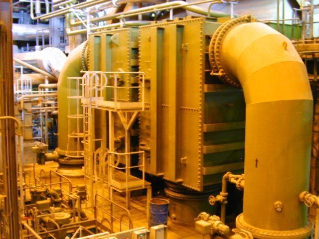
32 (CONDENSER) 32
33 ( CONDENSER TUBES) 33
34 ELECTROSTATIC PRECIPITATOR Electrostatic Precipitator ESP) is equipment, which utilizes an intense electric force to separate the suspended particle from the flue gases. In India coal is widely used to generate power. The exhaust gases from the furnace contains large amount of smoke and dust. If these gases are emitted directly into the atmosphere, it will cause great environmental problems. So it is necessary to extract this dust and smoke before emitting the exhaust gases into atmosphere. There are various methods of extracting dust but electrostatic precipitator is the most widely used. It involves electric changing of suspended particles, collection of charge particles and removal of charged particles from collecting electrodes. Its various other advantages are as follows: 1. It has high efficiency i.e. about 99% 2. Ability to treat large volume of gases at high temperature. 3. Ability to cope with the corrosive atmosphere. 4. It offers low resistance to the flow of gases. 5. It requires less maintenance. Working Principle: The electrostatic precipitator utilizes electrostatic forces to separate dust particles from the gases to be cleaned. The gas is passed through a chamber, which contains steel plates (vertical) curtains. These steel curtains divide the chamber into number of parallel paths. The framework is held in place by four insulators, which insulate it electrically from all parts, which are grounded. A high 34
35 voltage direct current is connected between the framework and the ground, thereby creating strong electric field between the wires in the framework curtains. Strong electric field develops near the surface of wire creates Corona Discharge along the wire. Thus ionized gas produces +ve and ve ions. In the chamber plates are positively charged whereas the wire is negatively charged. Positive ions are attracted towards the wire whereas the negative ions are attracted towards the plates. On their way towards the curtains negative ions strike the dust particles and make them negatively charged. Thus ash is collected on the steel curtain. The whole process is divided into the following parts: 1. Corona Generation. 2. Particle Charging. 3. Particle Collection. 4. Particle Removal. Corona Generation: Corona is a gas discharge phenomenon associated with the ionization of gas molecules by electron collision in regions of high electric filed strength. This process requires nonuniform electric filed, which is obtained by the use of a small diameter wire as one electrode and a plate or cylinder as the other electrode. The corona process is initiated by the presence of electron in strong electric field near the wire. In this region of corona discharge, 35
36 there are free electrons and positive ions. Both positive and negative coronas are used in industrial gas cleaning. In case of negative corona, positive ions generated are attracted towards the negative electrode or wire and the electrons towards collecting plates. On impact of negative ion thus generated, moves towards the collecting electrodes and serve as principle means of charging dust. Particle Charging: There are two physical mechanisms by which gas ions impact charge to dust particles in the ESP. Particles in an electric fields causes localized distortion in an electric filed so that electric field lines intersect with the particles. The ions present in the filed tend to travel in the direction of maximum voltage gradient, which is along electric field lines. Thus ions will be intercepted by the dust particles resulting in a net charge flow to the dust particles. The ions will be held to the dust particles by an induced image charge force between the ion and dust particle and become charged to a value sufficient to divert the electric field lines from particles such that they do not intercept. Particle Collection: The forces acting on the charged particles are Gravitational, Inertial, Electrostatic and Aerodynamically. The flow of gas stream is turbulent flow because it causes the particles to flow in random path through ESP. Particles will be collected at boundary layers of collector pates. But if flow is laminar, charge will act on particles in the direction of 36
37 collecting electrode. This force is opposite to viscous drag force and thus in the short time, particle would achieve Terminal (Migration) velocity at which electrical and viscous forces are equal. Thus the flow of the charged particles is decided by the vector sum of these forces i.e. Turbulent. Particle Removal: In dry removal of dust collected on plates, Rapping Mechanism is used. It consists of a geared motor, which moves a long shaft placed near the support collector electrode and is provided with cylindrical hammer. On rotating of shaft these hammers strikes the supports causes plates to vibrates and dust is removed from plates. Removed dust is collected in the Hoppers below the precipitator. At the time of starting of precipitation of dust from flue gases, the hoppers are at normal temperature bur the ash collected is very hot. So there is a chance of ash deposit at the exit of the hopper thus causing problem of removing the ash. To avoid this, heaters are provided which increase the temperature at the exit point of the hopper thus avoiding any undue accumulation of ash at starting. In order method, the water is allowed to flow down the collector electrode and hence dust is collected in hoppers below. 37
38 General Description: The whole Electrostatic Precipitator is divided into following two parts: Mechanical System. Electrical System. Mechanical system: Mechanical system comprises of Precipitator Casing, Hopper, Collecting and emitting system, and Rapping mechanism, Gas Distribution System. Precipitator Casing: Precipitator Casing is made of 6mm mild steel plate with required stiffness. The precipitator casing is all welded construction comprising of pre-fabricated walls and proof-panels. The roof carries the precipitator internals, insulator housing, transformer etc. Both emitting and collecting systems are hung from the top of the casing. Emitting and Collecting System: Emitting System is the most essential part of ESP. Emitting system consists of rigid emitting frame suspended from four points on the top and emitting electrodes in the form of open spiral. The four suspension points are supported on support insulators to give electrical insulation to the emitting frame. The frame is designed to take up the retention forces of the emitting electrode. The emitting electrodes consist of hard drawn spiral wires and are fastened with hooks to the discharge frame. 38
39 Collecting system mainly consists of collecting suspension frame, collecting electrodes and shock bars. Collecting electrodes are made of 1.6mm thick Mild Steel sheets formed in G Profile of 400mm width. Hook and guide are welded on one end and shock iron on the other end on a fixture. The electrodes are bundled together and dipped in rust preventive oil tank. Collecting electrodes bundles are properly bundled in order to avoid any damage to electrodes. Hoppers: Hoppers are seized to hold the ash for 8- hour collection and is provided under the casing of ESP. It is of Pyramidal Shape and is 56 in number. It is preferred to evacuate the hoppers at the earliest as long storage of dust in hopper leads to clogging of hopper. Also at the bottom of hopper electrical heating is provided to avoid any condensation, which could also lead to clogging of hopper. Baffle plates are provided in each hopper to avoid gas leakage. 39
40 DUST COLLECTING HOPPER WITH PNEUMATIC SYSTEM & SLURRY PUMP Rapping Mechanism: During electrostatic precipitation a fraction of the dust will be collected on the discharge electrodes and the corona will be suppressed as the dust layer grows. So, rapping is done in order to remove this dust by hammering the electrodes. As the shaft rotates the hammer tumbles on to the shock bar that transmits the blow to the electrode. The whole rapping mechanism is mounted on a single shaft, which is coupled with the gear drive motor. The rapping system avoids the collection of ash on the collecting electrode. Specification: Voltage and Current 415V and 5Amp. Power and Speed 3.7KW and 710 rpm. Gas Distribution System: The good performance of the ESP depends on even distribution of gas over entire cross section of field. Gas Distribution System distributes the gas evenly in ESP and maintains its efficiency. Electrical System: In precipitator we require high voltage dc supply to generate sufficient electric field. Electrical system comprises of High Voltage transformer Rectifier (HVR) unit with Electronic Controller (EC), Auxiliary control panel, Safety Interlocks and Field equipments. 40
41 Technical Specifications of ESP: Input to the thyristor controller 415 V (AC) Output of T/F or input to ESP 70 KV(DC) No. of ESP per unit 2 No. of fie;ds in series of gas path 7 Time of the flue gas pass through ESP 32.31sec No. of electrode per boiler 3780 No. of hoppers per unit 56 No. of rapping motors for collecting electrodes 14 per unit Normal height of collecting electrodes 12.5 m ESP Protections Short Circuit Protection: By under voltage relay 10-50% of primary volts with time delay from 10 sec to 80 sec can be adjusted. Over-Load Protection: By thermal overload relay on primary side. 41
42 COAL MILL Coal mills are mainly used to cursed the coal. It cursed the coal in powder form. The powder form o coal is known as scream. In the Unit-5, 6 coal mills are present in the unit. In which 5 are working & I is standby. CONSTRUCTION: 1. It have three roller, which are inclined at 120 degree angle to each other. 2. A whirl shaft is mounted on a motor. It makes 1400 r.p.m. 3. A-550 H.P. Motor used for rotation. It attached with shaft & it also attached with a gear, which further transfer power to three roller and gives motion. 4. Masinly three type bearing are used: a. Radial b. Thrust c. Radial support A pump is used for the lubrication oil, to transfer in the bearing & gear. 5. A gland is provided to prevent the leakage of oil & a indicator which gives indication of oil motion. 6. A inlet pipe, coming from coal bunker is feed the coal in the mill 42

43 7. R.C. feeder provide B/W the inlet pipe & coal bunker. 8. PA fan provide hot air from air preheater, for crushing purpose maintenance of temp. 9. Also cold air is provided to maintain the temp pipe line are used, which are used to transfer the scream coal to the furnace. 11. Conveyer belt is used to transferred out the unnecessary particle like concrete & small rock part from the coal mill. 43
44 COAL HANDLING PLANT - COAL MILL WORKING: Coal coming from CHM to coal bunker, which in small feed able parts. RC feeder control the feeds of the coal in the mill, three roller crushed the coal like as scream (as a powder form). Hot air supplied by PA fan help to crush the coal & cold air maintain temp. Gear present at the bottom is prevent the jamming by giving motion to the powder coal.pa fan maintain sufficient transfer pressure & the coal from 4 outlet pipe is given to the furnace. ASH HANDLING PALNT It is very import to control the ash coming from the furnace. 1. WET ASH HANDLING SYSTEM 2. DRYASH HANDLING SYSTEM A pipe line from ESP which contain the ash in divided in two parts. Use of Dry ash Evacuation instead of WET deashing System: Dry deashing system consumers less power & also minimizes waste reduction. The dry ash is directly transferred by vacuum system at desired place in plant it transfer to nearest cement factory. It is act as a good source of income for the plant. 44
45 The wet ash is transferred to the wet ash handling, in this vacuum created by water flow. Ash mix with the water and transferred to the ash pump from there it is drain out from the plant in to the lake. From here it is given to the raw water storage. Ash handling system The fly ash handling system evacuates the fly ash from the hopers, and transports the fly ash to reprocessing or to disposal. The ash handling system should be designed and operated to remove the collected fly ash from the hoppers without causing re-entertainment into the gas flow through the precipitator. The design of the ash handling system should allow for flexibility of scheduling the hopper discharges according to the fly ash being collected in these hoppers. Fly ash collection Fly ash is captured and removed from the flue gas by electrostatic precipitators or fabric bag filters (or sometimes both) located at the outlet of the furnace and before the induced draft fan. The fly ash is periodically removed from the collection hoppers below the precipitators or bag filters. Generally, the fly ash is pneumatically transported to storage silos for subsequent transport by trucks or railroad cars. 45
46 Bottom ash collection and disposal At the bottom of every boiler, a hopper has been provided for collection of the bottom ash from the bottom of the furnace. This hopper is always filled with water to quench the ash and clinkers falling down from the furnace. Some arrangement is included to crush the clinkers and for conveying the crushed clinkers and bottom ash to a storage site. WATER CLARIFIER It received impure water from raw water storage. In raw water storage big suspended particle settle down. CANAL RAW WATER STORAGE LAKE WATER CLARIFIER In water clarifier the purification of raw water held in two process. 1. Coagulation 2. Chlorination In coagulation Potash alum is added in the water. In this process the file suspended & colloidal particles are removed from water. In chlorination chlorine gas is added to the water, which have disinfectant action & it kills the harmful bacteria, germs & destroyed the pathogenic micro organism. 46
47 Excess of chlorine in water will effect to the taste of water. D.M. PLANT In the DM Plant the water is D-mineralized. The water is used for steam generation is must be free from colloidal & dissolved impurities. All the colloidal impurities are removed in the WATER CLARIFIER. Then the supplied to the DM Plant. Water clarifier DM PLANT Here the water contain dissolved impurities, which are mainly the salt of Ca, Na & Mg. It mainly sulphates & chloride etc CaSo4, NaCl, CaCl2 etc. In the DM Water Ist sent to the Sand filter & rest of the colloidal impurities are removed. Sand filter AC filter Cation tank- Gas tower Anion tank Now the water goes to the Activated Carbon filter. Here the excess of the chlorine is decomposed. 47
48 Then water supplied in the cation tank & in this cation (Ca++, Na+, Mg++) are removed & water with anion allow to pass ahead. R-H+ + NaCl R Na + H Cl HCl is added time to time to improve the conc. Of the cation tank. The process is known as the Regeneration. Then it allow to pass from the gas tower which removed the Co2 which producred during the purification process. Then it pass from the anion tank & all the anion Cl -, So4- - are removed out. Also regeration are done by adding any base solution, like NaOH etc. At last it passed in the mixed bed all the minerals present in the water removed & the water is completely free from minerals. STEAM CONDITION : Tri sodium phosphate & ammonia is added to maintain the ph of the water at specified value. Also another chemical N2H4 to remove the dissolved oxygen present in the water. Air Pre-heater Regenerative air pre-heaters cause temperature and SO3 stratification in the downstream gas flow. This problem is more severe in closely coupled systems, where the precipitator is located closed to the air preheater. 48
49 Depending upon site-specific conditions, flow mixing devices may be installed in the ductwork to the precipitator, or flue gas conditioning systems may be used to equalize the gas flow characteristics. Coal Burner The operation of coal burners, together with the setting of the coal mills and their classifiers, affects the percentage of unburned carbon (LOI or UBC) in the fly ash. The use of Lo-NOx burners increases this percentage, and caused reentertainment and increased sparking in the precipitator. Further, the UBC tends to absorb SO3, which in turn increases the fly ash resistivity. Over-fire air optimization or coal-reburn systems may reduce UBC in the fly ash. CHIMNEY : The gases produced due to burning of coal are comes out from chimney. The height of chimney is designed with respect to the boiler layout. The temp. is also maintained in the chimney. It is not more than 120 c. If it more than 120 c, then boiler will be corrupt.. Fly Ash and Flue Gas Conditioning Flur gas and fly ash characteristics at the inlet define precipitator operation. The combination of flue gas analysis, flue gas temperature and fly ash chemistry 49
50 provides the base for fly ash resisttivity involves both surface and volume resistivity. As gas temperature increases, surface conductivity decreases and volume resistivity increases. In lower gas temperature ranges, surface conductivity predominates. The current passing through the precipated fly ash layer is conducted in a film of weak sulfuric acid on the surface of the particles. Formation of the acid film (from SO3 & H2O) is influenced by the surface chemistry of the fly ash particles. In higher gas temperature ranges, volume conductivity predominates. Current conduction through the bodies (volume) of the precipitated fly ash particles is governed by the total chemistry of the particles. Fly ash resistivity can be modified (generally with the intent to reduce it ) by injecting one or more of the following upstream of the precipitator. Sulfur trioxide (SO3) Ammonia (NH3) Water 50
51 P.A. FANS: Functions of various parts of the cycle These fans are used to supply the hot air in order to dry powdered coal. To transport pulverized coal to the furnace the speed of PA fans 1400 rpm and they supply m 3 per hour. These are installed either side of boiler Air Heater: It is an essential part of a thermal power plant as hot air is necessary for rapid and efficient combustion in the furnace and also for drying coal in the milling plant. At PTPS tabular type air heater are being used it consists of large number of steel type welded to the tube plates at the end. Gas is allowed to flow through the tubes and cold air passes around these tubes and gets heated up. These air heaters provide primary as well as secondary air. 51

52 Secondary Air cycle In this cycle FD FANS suck air from the atmosphere and supply it to the wind box of the furnace through air heater and regulating dampers. Then it moves to the furnace as per requirements. Function of various parts F.D FANS These are used to take air from the atmosphere at ambient temp. to supply it to the furnace for combustion purpose. 52
53 Speed is about 990 r.p.m and it handles m 3 of air per hour These are installed either side of boiler WIND BOX This acts as distributing media for supplying secondary and excess air to combustion chamber. These are generally located at right and left side of the furnace while facing the chimney. 53

54 INDUCED DRAFT FANS (ID FANS) These are used to suck the flues gases from the furnace and through it into the stack so as to dispose them off into the atmosphere. It handles flash laden gases at a temp. Of 125 to 200degrees Its speed is around 970 rpm and it handles m 3 of air per hour These are installed at the outlet of electrostatic precipitator. 54
2x58 MW Coal Fired Power Plant at Mauritius
 2x58 MW Coal Fired Power Plant at Mauritius The coal-fired power plant produces electricity by the burning of coal and air in a Circulating Fluidized Bed Combustion Boiler (CFBC), where it heats water
ELECTRO STATIC PRECIPITATOR [ESP]
![ELECTRO STATIC PRECIPITATOR [ESP]](/thumbs/74/70995864.jpg "ELECTRO STATIC PRECIPITATOR [ESP]") ELECTRO STATIC PRECIPITATOR [ESP] Fußzeilentext 1 Controlling Air Pollution Clean Air is an essential resource to the people surrounding the industrial belts. Air pollution is one of the major contributor
ELECTRO STATIC PRECIPITATOR [ESP] Fußzeilentext 1 Controlling Air Pollution Clean Air is an essential resource to the people surrounding the industrial belts. Air pollution is one of the major contributor
APPLICATION PROFILE EXPLOSIONS IN CEMENT PLANTS EXPLOSIONS IN CEMENT PLANTS CEMENT PLANT EQUIPMENT WITH HIGHEST EXPLOSION POTENTIAL. Form No.
 APPLICATION PROFILE EXPLOSIONS IN CEMENT PLANTS Cement manufacturing is one of the largest mineral commodity industries in the United States, with an estimated production capacity of greater than 73 million
Boiler Basics. Design and operation
 Boiler Basics Design and operation A boiler is an enclosed vessel that provides a means for combustion heat to be transferred into water until it becomes heated water or steam. The hot water or steam under
ROTARY DRYER CONSTRUCTION
 ROTARY DRYER The Rotary Dryer is a type of industrial dryer employed to reduce or to minimize the liquid moisture content of the material it is handling by bringing it into direct contact with a heated
CHP-turbine room. CHP can capture almost EXTRACTED STEAM 20 PSI HIGH-PRESSURE STEAM 1250 PSI HEAT EXCHANGER HOT WATER SUPPLY F
 5 6 HIGH-PRESSURE STEAM is routed from the wood-chp boiler to the turbine. TURBINE BLADES spin at nearly 00 revolutions per second. Steam acting on the turbine blades creates mechanical energy in the TURBINE.
Analysis the effect of condenser pressure (vacuum) on efficiency and heat rate of steam turbine
 on efficiency and heat rate of steam turbine") Analysis the effect of condenser pressure (vacuum) on efficiency and heat rate of steam turbine 1 Muvva Murali Krishna 2 K.Mohan Krishna 3 A.V.Sridhar 4 J Hari Narayana Rao 1 M. Tech. Student, 3 Assistant.Professor
Analysis the effect of condenser pressure (vacuum) on efficiency and heat rate of steam turbine 1 Muvva Murali Krishna 2 K.Mohan Krishna 3 A.V.Sridhar 4 J Hari Narayana Rao 1 M. Tech. Student, 3 Assistant.Professor
ANNEX A-1 GEOTHERMAL UNITS INDEX TO SYSTEM/COMPONENT CAUSE CODES BOILER BALANCE OF PLANT STEAM TURBINE GENERATOR MISCELLANEOUS - GEOTHERMAL EXTERNAL
 ANNEX A-1 GEOTHERMAL UNITS INDEX TO SYSTEM/COMPONENT CAUSE CODES Boiler Piping System 0500-0620 Condensing System 3110-3199 Circulating Water Systems 3210-3285 Waste Water (zero discharge) 3290-3299 Condensate
Boiler Draft Equipment
 Boiler Draft Equipment Learning Outcome When you complete this module you will be able to: Discuss, sketch and describe the basic equipment used to supply combustion air to a boiler furnace. Learning Objectives
WHAT IS A BOILER? BOILER IS AN EQUIPMENT WHICH PRODUCES STEAM AT THE REQUIRED PRESSURE AND TEMPERATURE. BOILER DESIGN, MANUFACTURE & INSTALLATION ARE
 Your Logo Here TRAINING ON BOILERS PRESENTED AT M/S. MAGADI SODA COMPANY, MAGADI, KENYA LIMITED 1 WHAT IS A BOILER? BOILER IS AN EQUIPMENT WHICH PRODUCES STEAM AT THE REQUIRED PRESSURE AND TEMPERATURE.
1. Raw Material Handling: 2. Roaster Furnace: 4. Waste Heat Boiler: 5. Boiler Chain Conveyors:
 1. Raw Material Handling: The concentrate storage capacity is 40,000 MT and day bins are having 3 x 400 MT capacity. 2. Roaster Furnace: The Roaster is having 77 Sqr.Mtr hearth area of M./s Lurgi make
AUTOMATION OF BOILERS USING LABVIEW
 I J L S C M 4(1), 2012, pp. 49-53 AUTOMATION OF BOILERS USING LABVIEW A. MICHAEL SIDDHARTHA AND S. NAVEEN KUMAR Under Graduate Student, Department of Electronics and Communication Engineering Thiagarajar
PESIT-Bangalore South Campus
 USN PESIT Bangalore South Campus Hosur road, 1km before Electronic City, Bengaluru -560-100 Department of Mechanical Engineering INTERNAL ASSESSMENT TEST 2 Date : 03/04/2018 Max Marks : 50 Subject & Code
Pulse Jet Baghouse ASTEC PULSE JET BAGHOUSE. for Asphalt Facilities
 Pulse Jet ASTEC PULSE JET BAGHOUSE for Asphalt Facilities ASTEC PULSE JET BAGHOUSE FOR ASPHALT MIXING PLANTS Astec baghouses deliver superior performance and efficiency, while helping your plant meet
PERFORMANCE EVALUATION AND RECURRING JAMMING PROBLEM ANALYSIS OF AIR PREHEATER IN COAL-FIRED POWER PLANTS
 PERFORMANCE EVALUATION AND RECURRING JAMMING PROBLEM ANALYSIS OF AIR PREHEATER IN COAL-FIRED POWER PLANTS M.Srinivasa Rao M.Tech Student, Department of Mechanical Engineering, GMRIT, Srikakulam, AP, India.
M O D U L E IV C O N T R O L T E C H N I Q U E S
 M O D U L E IV C O N T R O L T E C H N I Q U E S GRAVITY SETTLING CHAMBER Gravity settling chamber is used to remove large and abrasive particles greater than 50 μ from a gas stream. This is a simple particulate
Annex A-8 CONCENTRATED SOLAR POWER UNITS INDEX TO SYSTEM/COMPONENT CAUSE CODES
 Annex A-8 CONCENTRATED SOLAR POWER UNITS INDEX TO SYSTEM/COMPONENT CAUSE CODES SOLAR ENERGY GATHERING EQUIPMENT Solar Field 6500-6559 Thermal Storage 6570-6589 Operational Problems 6590-6599 STEAM TURBINE
PIPING SYSTEM EQUIPMENTS
 PIPING SYSTEM EQUIPMENTS Introduction Equipments are devices that provide power, process and store materials. Equipments in piping systems depend on the specific industries using them. Specialized equipment
OFFICINE MINUTE VILLORBA - TREVISO
 OFFICINE MINUTE VILLORBA - TREVISO A15 A23 A25 A22 A23 A12 A14 A10 A21 A4 A3 A21 A2 A5 A21 A7 A21 A16 A17 A18 A21 A8 A1 A13 A14 A9 A19 A11 A20 A24 A1 - Linear gas burner A2 - Air mixing area A3 - Hot air
CENTRIFUGAL PUMPS. STATE the purposes of the following centrifugal pump components:
 Pumps DOE-HDBK-1018/1-93 CENTRIFUGAL PUMPS CENTRIFUGAL PUMPS Centrifugal pumps are the most common type of pumps found in DOE facilities. Centrifugal pumps enjoy widespread application partly due to their
CHAPTER 6. HEATING PRODUCTION EQUIPMENT AND SYSTEMS
 CHAPTER 6. HEATING PRODUCTION EQUIPMENT AND SYSTEMS 6.1 Types of Heating Systems 6.2 Heating Energy Sources 6.3 Furnaces and Air Heaters 6.4 Boilers 6.5 District Heating 6.6 Selection of Medium- Steam
Solution of I Mid Term Steam Engineering 6ME5A
 1(a) Discuss the working principle of LaMont high pressure boiler This boiler works on basic principle of forced convection. If the water is circulate by a pump inside the tube, the heat transfer rate
Lecture 5 Particulate emission control by electrostatic precipitation
 Lecture 5 Particulate emission control by electrostatic precipitation ELECTROSTATIC PRECIPITATORS The electrostatic precipitator is one of the most widely used collection devices for particulates. An electrostatic
GENERAL OVERVIEW OF NSPCL(ROURKELA) THERMAL POWER PLANT AND STUDY OF THE ELECTROSTATIC PRECIPITATOR
 THERMAL POWER PLANT AND STUDY OF THE ELECTROSTATIC PRECIPITATOR") A Project Report on GENERAL OVERVIEW OF NSPCL(ROURKELA) THERMAL POWER PLANT AND STUDY OF THE ELECTROSTATIC PRECIPITATOR By SAYANTAN JANA Under the guidance of J.ARATI(ENGR.,EMD) 1 NTPC-SAIL Power Company
A Project Report on GENERAL OVERVIEW OF NSPCL(ROURKELA) THERMAL POWER PLANT AND STUDY OF THE ELECTROSTATIC PRECIPITATOR By SAYANTAN JANA Under the guidance of J.ARATI(ENGR.,EMD) 1 NTPC-SAIL Power Company
Boiler Technical Specifications (2013)
") ACT Bioenergy Boiler Dimensions 0.5-0.85 Million Btu/h (150-250kW) Model CP500 CP600 CP750 CP850 Heat Output in MBtu/h (kw) 510 (150) 610 (180) 750 (220) 850 (250) Height ft (mm) 6 1 (1855) 6 1 (1855)
ACT Bioenergy Boiler Dimensions 0.5-0.85 Million Btu/h (150-250kW) Model CP500 CP600 CP750 CP850 Heat Output in MBtu/h (kw) 510 (150) 610 (180) 750 (220) 850 (250) Height ft (mm) 6 1 (1855) 6 1 (1855)
High Performance Diesel Fueled Cabin Heater. Abstract
 High Performance Diesel Fueled Cabin Heater Tom Butcher and James Wegrzyn Energy Science and Technology Division Building 526 Upton, N.Y. 11973 Brookhaven National Laboratory Abstract Recent DOE-OHVT studies
B.Tech. First Semester Examination Basics of Mechanical Engineering (ME-101F)
") B.Tech. First Semester Examination Basics of Mechanical Engineering (ME-101F) Q. 1. (a) Differentiate between water tube boiler and fire tube boiler. Ans. Comparison Between 'Fire-tube and Water tube'
B.Tech. First Semester Examination Basics of Mechanical Engineering (ME-101F) Q. 1. (a) Differentiate between water tube boiler and fire tube boiler. Ans. Comparison Between 'Fire-tube and Water tube'
Variable speed hydraulic coupling and drive unit of hydraulic coupling
 Variable speed hydraulic coupling and drive unit of hydraulic coupling I. Model designation YO / / / Modificait on code Output speed of drive unit (r/min) Input speed of coupling or drive unit (r/min)
[1] Lecture 2 Particulate emission control by mechanical separation & wet gas scrubbing
![[1] Lecture 2 Particulate emission control by mechanical separation & wet gas scrubbing](/thumbs/89/99244801.jpg "[1] Lecture 2 Particulate emission control by mechanical separation & wet gas scrubbing") [1] Lecture 2 Particulate emission control by mechanical separation & wet gas scrubbing PARTICULATE EMISSION CONTROL BY MECHANICAL SEPARATION The basic mechanism of removing particulate matter from gas
[1] Lecture 2 Particulate emission control by mechanical separation & wet gas scrubbing PARTICULATE EMISSION CONTROL BY MECHANICAL SEPARATION The basic mechanism of removing particulate matter from gas
Appendix B9 Geothermal Unit Cause Codes
 Appendix B9 Geothermal Unit Cause Codes GEOTHERMAL UNITS INDEX TO SYSTEM/COMPONENT CAUSE CODES (Unit Codes 800 899) Cause Code BOILER Ranges Page No. Boiler Piping System 0500-0620 B-GE-2 BALANCE OF PLANT
MODEL ANSWER FOR ELEMENTS OF MECH.ENGG.(17413) 1) steam boiler- It is a closed vessel in which steam is produced from water by combustion of fuel.
 1) steam boiler- It is a closed vessel in which steam is produced from water by combustion of fuel.") MODEL ANSWER FOR ELEMENTS OF MECH.ENGG.(17413) Q 1. a) 1) steam boiler- It is a closed vessel in which steam is produced from water by combustion of fuel. 2) steam turbine- It is a device that extract
MODEL ANSWER FOR ELEMENTS OF MECH.ENGG.(17413) Q 1. a) 1) steam boiler- It is a closed vessel in which steam is produced from water by combustion of fuel. 2) steam turbine- It is a device that extract
ASSSIGNMENT 3. Textbook Assignment: Boilers, chapter 4, pages 4-1 through 4-15, and Steam Turbines, chapter 5, pages 5-1 through 5-1.
 ASSSIGNMENT 3 Textbook Assignment: Boilers, chapter 4, pages 4-1 through 4-15, and Steam Turbines, chapter 5, pages 5-1 through 5-1. 3-1. What is the function of a boiler in the steam cycle? 1. To convert
Boiler. Fire tube Boiler:
 Boiler What is Boiler? A closed metallic vessel in which the water is heated beyond the boiling temperature by the application of heat by the combustion of fuels to convert it into steam. The function
Annex A-7 FOSSIL STEAM UNITS INDEX TO SYSTEM/COMPONENT CAUSE CODES
 BOILER Boiler Fuel Supply to Bunker 0010-0129 Boiler Fuel Supply from Bunkers to Boiler 0200-0480 Boiler Piping System 0500-0799 Boiler Internals and Structures 0800-0859 Slag and Ash Removal 0860-0920
CHAPTER 2: PROPERTIES OF STEAM AND STEAM POWER
 CHAPTER 2: PROPERTIES OF STEAM AND STEAM POWER Steam produced from water forms one of the most important working fluids in engineering energy conversion systems. The advantages of using steam (water) as
Appendix B Index to System/Component Cause Codes
 Appendix B Index to System/Component Cause Codes Using This Appendix This appendix contains system/component cause codes to use when completing GADS Event Report (07). For ease of use, it is divided into
HEAT EXCHANGE IN GENERAL
 XXXX F28 HEAT EXCHANGE IN GENERAL Note(s) (1) In this class, the following expressions are used with the meanings indicated: heat exchange means the heating or cooling of a fluid or fluent solid by direct
Solid and Liquid Pollutants
 Solid and Liquid Pollutants Learning Outcome When you complete this module you will be able to: Discuss the nature, environmental impacts and control methods for solid and liquid pollutants in a power
CHAPTER 3 BASIC STEAM CYCLE
 CHAPTER 3 BASIC STEAM CYCLE To understand steam generation, you must know what happens to the steam after it leaves the boiler. A good way to learn the steam plant on your ship is to trace the path of
Small size, big energy savings
 ATOX coal mill 2 Small size, big energy savings Key benefits - Handles all types and capacities of coal - Reliable, long-lasting operation - Simple, flexible operation - Superior separation efficiency
When you complete this module you will be able to: Describe various watertube boiler designs, including large generating units.
 Watertube Boilers Learning Outcome When you complete this module you will be able to: Describe various watertube boiler designs, including large generating units. Learning Objectives Here is what you will
Household devices, <-<>al breaker rolls, stone crusher, four early types of power devices.
 SECTION VI Nos. 81 06 Household devices,
TMCI Padovan Evaporators
 TMCI Padovan Evaporators Evaporators Our range includes 4 types of evaporators: Forced Circulation Falling Film Evaporators Plates Thin Film Concentration systems Evaporator choosing criteria: product
LIQUID RING PUMPS FOR THE POWER INDUSTRY
 LIQUID RING PUMPS FOR THE POWER INDUSTRY VACUUM SOLUTIONS FOR THE POWER PLANT for The Power Industry 334 Shop online at shop.edwardsvacuum.com Contact our customer service team for the Power Industry 333.
MIX Type Blenders. I Application. I Principle of operation
 MIX Type Blenders MSMIX I Application INOXPA's MIX type blenders have been designed specifically for mixing low or high viscosity liquid products for the food, cosmetics, pharmaceutical and chemical industries.
Steam Fundamentals. (in heating & processing applications)
") Steam Fundamentals (in heating & processing applications) Introduction Common Heat Energy conveyers: Thermal Oil Hot water Steam Electrical Electric Heaters Electrodes (High Current) Steam Fundamentals
Steam Fundamentals (in heating & processing applications) Introduction Common Heat Energy conveyers: Thermal Oil Hot water Steam Electrical Electric Heaters Electrodes (High Current) Steam Fundamentals
Rotodynamic Pumps INTRODUCTION:
 Rotodynamic Pumps INTRODUCTION: Liquids have to be moved from one location to another and one level to another in domestic, agricultural and industrial spheres. The liquid is more often water in the domestic
COOPERATIVE PATENT CLASSIFICATION
 CPC F COOPERATIVE PATENT CLASSIFICATION MECHANICAL ENGINEERING; LIGHTING; HEATING; WEAPONS; BLASTING (NOTE omitted) LIGHTING; HEATING F28 HEAT EXCHANGE IN GENERAL (NOTES omitted) F28D HEAT-EXCHANGE APPARATUS,
Problem Cause Remedial action. Gauge glass There was excess chemical dosage The normal ph recommended was 9.5 to See photo 3 & 4.
 CASE STUDIES OF STEAM SYSTEM AUDIT IN SOME PLANTS By K.K.Parthiban, Venus Energy Audit System Introduction This article outlines the outcome of auditing of steam system conducted in process Industries.
Evaporation System: Types and Design Aspects
 Evaporation System: Types and Design Aspects Dr. Pankaj Kumar, Er. Dhritiman Saha and Er. Chandan Solanki Food Grains and Oil Seeds Processing Division, ICAR-CIPHET, Ludhiana Evaporation is an important
TECCON. 2,5 to 10,0 t / H Water evaporation RATE
 TECCON BELT DRYER 2,5 to 10,0 t / H Water evaporation RATE Installation of belt dryer 2 TECCON belt dryer Belt dryer 2,5 to 10,0 t / H Water evaporation RATE 1 Zentrales Element im Pelletswerk Norica ist
Ball Float Controlled. Thermo Dynamic(TD) Trap Safety Valve Condensate Pump Flash Vessel Moisture Separators Deaerator Head Steam Injector Sight Glass
 Trap Safety Valve Condensate Pump Flash Vessel Moisture Separators Deaerator Head Steam Injector Sight Glass") Product of Quality Best Performance Ball Float Controlled Steam Traps Auto Drain Traps Float Valve Air Vent Valves Feed Control Valve Drain Control Valve Thermo Dynamic(TD) Trap Safety Valve Condensate
Product of Quality Best Performance Ball Float Controlled Steam Traps Auto Drain Traps Float Valve Air Vent Valves Feed Control Valve Drain Control Valve Thermo Dynamic(TD) Trap Safety Valve Condensate
CENTRIFUGAL BLOWERS & FANS TM MITTAL ENGINEERING
 CENTRIFUGAL BLOWERS & FANS TM MITTAL ENGINEERING TM MITTAL ENGINEERING M i t t a l E n g i n e e r i n g i s o n e o f t h e l e a d i n g m a n u f a c t u r e r s q u a l i t y e n g i n e e r i n g
Steam Generator (Boiler) & Steam Turbine. Steam Generator (Boiler) ME 268. Model Lab
 & Steam Turbine. Steam Generator (Boiler) ME 268. Model Lab") Steam Generator (Boiler) ME 268 Model Lab Aashique Alam Rezwan Lecturer Department of Mechanical Engineering, BUET, Dhaka-1000 http://teacher.buet.ac.bd/aashiquear ME 268 Aashique Alam Rezwan 1 Modern
Steam Generator (Boiler) ME 268 Model Lab Aashique Alam Rezwan Lecturer Department of Mechanical Engineering, BUET, Dhaka-1000 http://teacher.buet.ac.bd/aashiquear ME 268 Aashique Alam Rezwan 1 Modern
Attention is drawn to the following places, which may be of interest for search:
 CPC - F22B - 2017.02 F22B METHODS OF STEAM GENERATION; STEAM BOILERS (steam engine plants where engine aspects predominate F01K; domestic central-heating systems using steam F24D; heat exchange or heat
Annex A-6 FLUIDIZED BED COMBUSTION UNITS INDEX TO SYSTEM/COMPONENT CAUSE CODES
 Annex A-6 FLUIDIZED BED COMBUSTION UNITS INDEX TO SYSTEM/COMPONENT CAUSE CODES BOILER Boiler Fuel Supply to Bunker 0010-0129 Sorbent Supply (FBC) 0130-0156 Bed Material Preparation System (FBC) 0160-0174
CASE STUDY ON EFFICIENCY & AVAILABILITY DETERIORATION IN AN AFBC BOILER
 CASE STUDY ON EFFICIENCY & AVAILABILITY DETERIORATION IN AN AFBC BOILER By K.K.Parthiban / Venus Energy Audit System & Sri Devi Boiler Equipment and Spares. Introduction This case study is about various
MECHANICAL ENGINEERING ME.2017 FUNDAMENTAL OF REFRIGERATION AND AIR CONDITIONING. Sample Questions and Answers
 MECHANICAL ENGINEERING ME.2017 FUNDAMENTAL OF REFRIGERATION AND AIR CONDITIONING Sample Questions and Answers CHAPTER 5 EVAPORATORS 1. What is Evaporator? Classify the various types of evaporator. Evaporator
CPF PRODUCT DESCRIPTION
 CPF 175 340 PRODUCT DESCRIPTION The CHICAGO PNEUMATIC CPF 175-340 compressor is a quiet, complete and ready-for-use unit for the production of compressed air in industrial applications. OVERVIEW The CHICAGO
POWER VENTER SYSTEM. Model: PVO-300, PVO-600
 POWER VENTER SYSTEM Model: PVO-300, PVO-600 Included is one ETL and cetl listed Power Venter to be used primarily with a single 120VAC controlled oil fired furnace, boiler, or water heater. The PVO may
DS series STERLING PUMPS. Industrial End Suction Pumps ISO/DP
 DS series Industrial End Suction Pumps ISO/DP 5199 www.sterlingpumps.com.au DS series Capacities from: Heads from: 340 to 5,680 m3/h (1,500 to 25,000 USPGM) 21 to 106 metres (70 to 350 feet) Power range
9707 Key West Avenue, Suite 100 Rockville, MD Phone: Fax:
 9707 Key West Avenue, Suite 100 Rockville, MD 20850 Phone: 301-740-1421 Fax: 301-990-9771 E-Mail: awt@awt.org Part of the recertification process is to obtain Continuing Education Units (CEUs). One way
4VH and 4VHX. 4" Non-Clog Wastewater Pumps Standard (4VH) and Explosion-Proof (4VHX) Construction
 and Explosion-Proof (4VHX) Construction") 4VH and 4VHX 4" Non-Clog Wastewater Pumps Standard (4VH) and Explosion-Proof (4VHX) Construction DURABLE MOTOR WILL DELIVER MANY YEARS OF RELIABLE SERVICE Oil-filled motor for maximum heat dissipation
4VH and 4VHX 4" Non-Clog Wastewater Pumps Standard (4VH) and Explosion-Proof (4VHX) Construction DURABLE MOTOR WILL DELIVER MANY YEARS OF RELIABLE SERVICE Oil-filled motor for maximum heat dissipation
Title: YALE OFFICE OF FACILITIES PROCEDURE MANUAL Chapter: 01 - Yale Design Standard Division: HVAC Standards
 Date Description of Change Pages / Sections Modified ID 6/15/16 Entire document - mgl44 PART 1 - INTRODUCTION 1.1 PURPOSE A. This section is intended to define the general installation and minimum product
AIM OF THE EXPERIMENT:- Study of boilers (fire tube, water tube) APPARATUS REQUIRED: - SL.NO NAME OF THE APPARATUS SPECIFICATION QUANTITY 01 Fire tube
 APPARATUS REQUIRED: - SL.NO NAME OF THE APPARATUS SPECIFICATION QUANTITY 01 Fire tube") LABORATORY MANUAL ON STUDY OF FIRE TUBE AND WATER TUBE BOILERS Prepared By Prof. (Dr.) M. K. Roul Professor and Principal, Gandhi Institute for Technological Advancement (GITA), Bhubaneswar 752054 June
LABORATORY MANUAL ON STUDY OF FIRE TUBE AND WATER TUBE BOILERS Prepared By Prof. (Dr.) M. K. Roul Professor and Principal, Gandhi Institute for Technological Advancement (GITA), Bhubaneswar 752054 June
Tel Group
 www.wamechsi.com Tel +27 12 808 0682 sales@wamechsi.com VERTICAL SHAFT, LOW SPEED, AERATORS Technical Specifications Vertical shaft, low speed aerators are ideal for the bacterial oxidization of effluent
PVE SERIES POWER VENTER SYSTEM MANUAL
 PVE SERIES POWER VENTER SYSTEM MANUAL Contents Page I. Typical Venting System Components 2 II. System Operation 3 III. Power Venter Sizing 3,4 IV. Installation Safety Instructions 5,6 V. Installation of
INTRODUCTION TO DUSTS AND THEIR EXPLOSIVE PROPERTIES
 INTRODUCTION TO DUSTS AND THEIR EXPLOSIVE PROPERTIES Olof Bekker Pr. Eng. BSc. Eng. BML S.MSAIEE, M.NACE Engineering Manager, Electrical and Facilities DUST EXPLOSION! 1 DEFINITION Dust consists of small
Document Code: 1 (15) Issuing date: Status:
 Issuing date: Status:") Document Code: 1 (15) Project : MULTI FUEL CFB BOILER SIMULATOR Author: Approved: Language: HSK Document title: SYSTEM DESCRIPTION BOILER WATER SYSTEM Submitted for: Customer reference: Other information:
Document Code: 1 (15) Project : MULTI FUEL CFB BOILER SIMULATOR Author: Approved: Language: HSK Document title: SYSTEM DESCRIPTION BOILER WATER SYSTEM Submitted for: Customer reference: Other information:
Brown Hills College of Engineering & Technology
 UNIT 6 Steam Condensers Elements of a condensing plant, Types of condensers, Comparison of jet and surface condensers, Condenser vacuum, Sources of air leakage & its disadvantages, Vacuum efficiency, Condenser
HIGH PRESSURE DOUBLE CASE PUMPS
 HIGH PRESSURE DOUBLE CASE PUMPS Horizontally Split Inner Casing, Multi Stage For Boiler Feed, Process and Other High Pressure Services CS1860EE Models HSB/HDB API 610 HIGH PRESSURE DOUBLE CASE PUMPS Horizontally
qüé=`üáãåéó An effective chimney is an important part of any successful wood-burning system.
 8. qüé=`üáãåéó An effective chimney is an important part of any successful wood-burning system. How Chimneys Work An effective chimney is an important part of any successful wood-burning system. Many of
Specialized in the design and the tailor-made production of dryers, coolers and thermal processing equipment for industrial use.
 Specialized in the design and the tailor-made production of dryers, coolers and thermal processing equipment for industrial use. Thermal processing solutions Ingetecsa supplies thermal processing solutions
SECOND HAND ASPHALT PALANT FOR SALE
 . BITUMEN STORAGE DREDGING EQUIPMENT QUARRY INSTALLATIONS. Unit 1, Burnhouse Industrial Estate, Burnhouse Industrial Estate, Whitburn, West Lothian, EH47 0LQ SECOND HAND ASPHALT PALANT FOR SALE Manufacturer:
LIMESTONE HANDLING AND LIME MILLING SYSTEM
 LIMESTONE HANDLING AND LIME MILLING SYSTEM PURPOSE TO REDUCE THE SOx LEVEL AS PER STATUTARY REQUIREMENT TO REDUCE CORROSION EFFECT ON APH TUBES AND FLUE GAS PATH TO FEED THE LIME POWDER TO BUNKER AFTER
OPTIMISATION OF SOOT BLOWER OPERATION IN BOILER TO IMPROVE EFFICIENCNY
 OPTIMISATION OF SOOT BLOWER OPERATION IN BOILER TO IMPROVE EFFICIENCNY K.Vijay 1, Dr. B. Karthikeyan 2 1PG Student, Department of Mechanical Engineering, Annamalai University, chidambaram. 2Associate professor,
Centrifugal Fans, Non-Overloading, Backward Inclined
 BACKWARD INCLINED CENTRIFUGAL FANS Centrifugal Fans, Non-Overloading, Backward Inclined MVA, MVZ, MVX & MVW Series with laminar blades MAVA, MAVZ & MAVX Series with aerofoil blades Features The combination
Compound Fertilizer Production Line Project Proposal
 Compound Fertilizer Production Line Project Proposal Shandong Tianli R&D Institute July, 2008 1. General 1.1 Introduction According to the fertilizer standard of GB15063-2001, a compound fertilizer is
LONGONI ENGINEERING SRL
 INDEX 1.1 Classification of heat exchanger and components 1.1.2 Type of heat exchanger and components 1.2 Purpose and scope of the manual 1.3 General instruction 1.4 Warning installation 1.5 Notes for
Document Code: 1 (13) Issuing date: Status:
 Issuing date: Status:") Document Code: 1 (13) Project : MULTI FUEL CFB BOILER SIMULATOR Author: Approved: Language: JJA Document title: SYSTEM DESCRIPTION REHEAT STEAM SYSTEM Submitted for: Customer reference: Other information:
Document Code: 1 (13) Project : MULTI FUEL CFB BOILER SIMULATOR Author: Approved: Language: JJA Document title: SYSTEM DESCRIPTION REHEAT STEAM SYSTEM Submitted for: Customer reference: Other information:
FLUIDIZED BED BOILERS
 FLUIDIZED BED BOILERS Proven technology for burning fuels on solid grate with a fountain fluidized layer; The possibility of burning a wide variety of solid fuels - with large heated value range coal,
Division III Process Gas Treatment Equipment
 ASME AG-1 Committee on Nuclear Air and Gas Treatment Division III Process Gas Treatment Equipment Chairman, SC Gas Process Treatment August 2008 - p 1 ASME AG-1 Division I General Requirements Division
POWER VENTER. Model: PVE Series
 POWER VENTER Model: PVE Series CONTENTS Typical Venting System Components... System Operation... Power Venter Sizing... Installation Safety Instructions... Installation of Power Venter... Connecting Power
Heat Exchanger. The purpose may be either to remove heat from a fluid or to add heat to a fluid.
 HEAT EXCHANGERS Heat Exchanger Heat exchanger is an apparatus or an equipment in which the process of heating or cooling occurs. The heat is transferred from one fluid being heated to another fluid being
Rotary Metal Parts Treatment System; Rotary Metal Parts Treater RMPT Effluent Heater MPT Quench Tower Rotary Metal Parts Treater
 1 1 1 1 1 1 1 1 0 1 Rotary Metal Parts Treatment System; Rotary Metal Parts Treater (00-MPT-1), RMPT Effluent Heater (00-HEAT-1), and MPT Quench Tower (00-TOWR-1). There will be one Rotary Metal Parts
LN series STERLING PUMPS. Horizontal Split Case Pumps. Double Volute. Single Stage.
 LN series Horizontal Split Case Pumps Double Volute. Single Stage www.sterlingpumps.com.au LN series Sizes: 6 to 42 Capacity to 12,500 m³/h Heads to 190 metres A rugged, single stage, double volute horizontal
Module 3: Liquid Fossil Fuel (Petroleum) Lecture 25: Refinery Equipments
 Lecture 25: Refinery Equipments") 1 P age Module 3: Liquid Fossil Fuel (Petroleum) Lecture 25: Refinery Equipments 2 P age Keywords: Pipe still heater, heat exchangers, distillation tower, pumps Refinery equipments Introduction In refinery,
1 P age Module 3: Liquid Fossil Fuel (Petroleum) Lecture 25: Refinery Equipments 2 P age Keywords: Pipe still heater, heat exchangers, distillation tower, pumps Refinery equipments Introduction In refinery,
2How does a vibratory fluid-bed dryer work?
 As appeared in April 2011 PBE Copyright CSC Publishing www.powderbulk.com Answers to five common questions about vibratory fluid-bed dryers Doug Schieber Carrier Vibrating Equipment A vibratory fluid-bed
CPVS PRODUCT DESCRIPTION
 CPVS 20 30 PRODUCT DESCRIPTION The CHICAGO PNEUMATIC CPVS 20-30 compressor is a quiet, complete and ready-for-use unit for the production of compressed air for light and medium industrial applications.
9. Cooling Water System
 9.1 Water quality The fresh water in the cooling water system of the engine must fulfil the following requirements: ph... Hardness... Chlorides... Sulphates... min. 6.5...8.5 max. 10 dh max. 80 mg/l max.
Introduction Airflow and filtration area General design practices Cleaning system
 FACING THE CHALLENGE JOHN RENNOCKL, CLARCOR INDUSTRIAL AIR, USA, PROVIDES HELPFUL HINTS FOR THE DESIGN EVALUATION AND OPERATION OF COAL MILL DUST COLLECTORS. Introduction Today s regulatory climate has
Unit Design Data. Fossil Steam
 Fossil Steam Units Appendix E Unit Design Data Forms Unit Design Data Fossil Steam Instructions Use these forms to report design and installed equipment information for FOSSIL (steam) units. FOSSIL units
Coarse Coal Centrifuges. VM1650 is the world s largest capacity Coarse Coal Centrifuge
 Process Equipment 2 3 Coarse Coal Centrifuges VM1650 is the world s largest capacity Coarse Coal Centrifuge FLSmidth Ludowici manufactures a range of centrifuges that have established an unequalled track
BASIL 6000 TUNNEL CAGE WASHER
 BASIL 6000 TUNNEL CAGE WASHER APPLICATION For thorough, efficient cleaning of cages, debris pans, bottles, feeder bowls, and miscellaneous items used in the care of laboratory animals. DESCRIPTION The
UNIT 6 STEAM CONDENSERS
 UNIT 6 STEAM CONDENSERS Steam Condensers Structure 6.1 Introduction Objectives 6.2 Condenser Types 6.3 Steam Surface Condenser Operation 6.3.1 Steam Surface Condenser Configurations 6.3.2 Water-cooled
ADVANCED Series 15P1 17P2 19P2
 A WIRTGEN GROUP COMPANY Continuous Mobile Asphalt Plants ADVANCED Series 15P1 17P2 19P2 02 03 The Advanced plants line combines the maximum portability of a continuous production plant with the quality
Brown University Revised August 3, 2012 Facilities Design & Construction Standards SECTION AIR HANDLING UNITS
 SECTION 23 70 00 AIR HANDLING UNITS PART 1. GENERAL 1.1 Section includes air-handling units to 15,000 cfm and accessories. 1.2 Related Sections 1 : A. Division 01 - Brown University Standard for Narragansett
Energy Conservation with PARAG Energy Efficient Axial Flow FRP Fans
 PARAG FANS & COOLING SYSTEMS LTD. Energy Conservation with PARAG Energy Efficient Axial Flow FRP Fans Registered Office & Works Plot No.1/2B & 1B/3A, Industrial Area No.1 A.B.Road, Dewas 455001 (M.P.)
Ontario Fire Code SECTION 5.10 COMBUSTIBLE DUST PRODUCING PROCESSES. Illustrated Commentary. Office of the Ontario Fire Marshal
 Ontario Fire Code SECTION 5.10 COMBUSTIBLE DUST PRODUCING PROCESSES Illustrated Commentary Office of the Ontario Fire Marshal Combustible Dust Illustrated Commentary 1 Mechanical Exhaust Systems 5.10.1.1.
PAPER INDUSTRY PROCESS DESCRIPTION
 PAPER INDUSTRY PROCESS DESCRIPTION Paper Industry PROCESS DESCRIPTION SUMMARY- PART 1. PAPER PASTE GENERATION 1. Raw material 2. First paper separation 3. Second paper separation 2 Paper Industry PROCESS