BOILER 3CL LUNARIO 3CL MACARUBBO 3CL SAGAYO 3CL LUMIGUEN 3CL MIRADOR
|
|
|
- Clifford Chase
- 5 years ago
- Views:
Transcription
1 BOILER 3CL LUNARIO 3CL MACARUBBO 3CL SAGAYO 3CL LUMIGUEN 3CL MIRADOR
2 What is a boiler? Boilers use fuel to heat water or steam and circulate the hot water through pipes. The hot water produced is then used to heat a building and/or produce hot water for personal or industrial use. For example a boiler used as a heating system in a home would have radiators in a house or part of a building. The boiler heats the water for use and also circulates that hot water through the pipes and the radiator, heating the rooms. A boiler uses circulated hot water whereas a furnace, found in many homes today, uses forced air and circulates it through vents. Types of boilers include steam turbine, package boilers, steam generators, clean steam packages, hot water heaters, hot oil heaters, boilers and vaporizers. A package boiler is a boiler that is ordered with all necessary parts included, assembled and ready to use. Very little installation is required. Steam boilers are used to produce steam for industrial usage such as cleaning. Boilers vary in size and shape. A boiler used for a residence is going to be small enough to fit in the corner of a room, where are industrial boilers can be large enough to fill up an entire room. Depending on the amount of heat it needs to generate and what exactly it will be used for. Refurbishing a boiler If you now have a boiler and are considering replacing it you have a few options. Boilers have a general life of years. If there are parts on your boiler that are not working you may consider getting it refurbished, buying a used boiler that has been refurbished already, or getting new parts. When a boiler is replaced it's often sent out to be remanufactured. The boiler is disassembled, cleaned, refurbished and then sent back out to operation or put on the market. The parts of the boiler are inspected and cleaned. If a part is no longer working and it is irreparable, it will be discarded, only parts that are safe and in working order are refurbished. It is common for brand new parts to be used with refurbished parts or systems. A boiler that has been refurbished can come out of the shop looking like new and work just as well as a new one, and for a much lower cost. Other benefits If the decision has been made to purchase a brand new boiler, consider sending your used boiler to get refurbished so that someone else can use it. Boilers can almost always be refurbished and recycled, if not for the whole boiler can usually be disassembled for parts. There may be a non-profit organization or church in your area that is in need of a boiler but cannot afford to purchase a new one. Having a used boiler available to purchase or given as a donation, would be a huge help to any organization. The benefits of used boilers extend beyond that. Buying used boilers benefits the environment by helping to keep used appliances and materials out of landfills and it creates jobs at recycling and remanufacturing plants.
3 INTRODUCTION The D-type boiler has been installed in U.S. Navy ships since Whether 600 psi or 1200 psi, D-type boiler construction is basically the same with a few exceptions, such as number of fuel oil burners and overall size and volume. REFERENCES (a) Boilers NSTM Chapter 221 (b) Fireman NAVEDTRA Series (c) Boiler Technician 3&2 NAVEDTRA 10535B (d) Principles of Naval Engineering H (e) Boiler Operation and Maintenance Manual NAVSEA 0951-LP INFORMATION A. Main propulsion boilers provide steam to the main propulsion turbines and auxiliary services in order to supply all shipboard steam systems in accordance with demand. (refer to Figure 1). It is designated as a D-type boiler because of the relative positions of the drums and side header which form the letter D. All D-type boilers are designated as uncontrolled superheat boilers because all the steam generated by the boiler must pass through the superheater. Superheater outlet temperature is a result of the combustion gas flow in proportion to the total amount of steam flow through all ranges (0-120%). The design characteristics ensure that the temperature will stabilize at set point. The degree of superheat is calculated by subtracting steam drum temperature from the actual reading on the superheater outlet temperature gage. In this lesson we will examine the components of the boiler and then we will bring everything together by describing how water and steam is generated and circulated through the boiler. The flow path of combustion gases through the boiler will also be discussed. D TYPE BOILER
 The incoming feedwater absorbs about 100-200 F sensible heat from the exhaust gases.")
4 B. The economizer is a multi-pass heat exchanger located above the main generating bank at the base of the exhaust stack, so that combustion gas will give up a lot of its remaining heat to the incoming feedwater before passing out the stack (Refer to Figure 2) The incoming feedwater absorbs about F sensible heat from the exhaust gases. Fins are installed on the economizer tubes to increase the heating surface area further, helping to increase efficiency. ECONOMIZER
5 C. The steam drum is located at the top of the boiler to provide an upper reservoir for the water covering the generating tube bank. Water is distributed from the steam drum to the lower drums and headers by pipes called downcomers. Generated steam is also collected and is separated from the water in the steam drum. Boilers are also equipped with safety valves to relieve excessive pressure. The valves are located on the steam drum and superheater outlet. They are designed to relieve sufficient pressure to safely steam the boiler at 120% with boiler steam stop valves closed (refer to Figure 3). These valves are discussed in detail in lesson 62B-206. D. Air vents or air cocks are installed on top of the steam drum to expel air from inside the steam drum during cold boiler light-off or when filling the boiler. The air vents or air cocks are shut when the boiler starts generating steam. SAFETY VALVE CONFIGURATION
6 E. The internal fittings in the steam drum help distribute the water evenly throughout the drum, separate the generated steam from the water and remove moisture from the steam before it leaves the boiler (refer to Figure 4). 1. Lower baffle plates or apron plates Separate the incoming feedwater and generated steam and direct the steam to the separators. 2. Primary separators (cyclone separators) Separate most of the water from the steam by giving it a cyclone or rotary motion so that the water particles are expelled from the steam by the centrifugal forces. These separators are vertically mounted in the steam drum so that the steam rises out the top and the water falls back into the steam drum. 3. Secondary separators (chevron dryers) Remove additional moisture from the steam by changing the direction of steam flow several times. The steam passes on but the moisture cannot make the direction change with the steam. These separators are mounted above the primary separators and direct steam to the dry box which collects the steam at the top of the steam drum, directing it to the steam outlet piping to the superheater. 4. Feedwater leaves the economizer and enters the boiler through the internal feed pipe and becomes "boiler water." Perforations along the side of the feed pipe allow water to be distributed evenly throughout the steam drum (refer to Figure 4) STEAM DRUM INTERNALS
7 5. Since suspended solids may accumulate on the surface of the water in the steam drum, there must be means of removing them. The surface blow pipe is used to remove these light suspended solids from the surface of the water and to reduce the total dissolved solid content of the boiler water. Suspended solids usually consist of oil, salt contaminants, or excessive treatment chemicals which can cause foaming on the water surface. Dissolved solids usually consist of salt contaminants and treatment chemicals that are in solution. F. The D-type boiler uses the principle of accelerated natural circulation to circulate water through the boiler. To enable this principle to work, relatively cool water will naturally circulate through large diameter pipes to distribution points low in the boiler. The downcomers are these large diameter pipes connecting the steam drum with the water drum and lower headers to ensure proper circulation by delivering water from the steam drum to the water drum and lower headers. The downcomers are located between the inner and outer air casing to protect them from the direct radiant heat of the furnace. G. The water drum is located at the bottom of the boiler below the main generating bank and acts as a lower reservoir of water for distribution to the main generating bank. Also, this large drum serves as a collection point for solids (sludge) that precipitate to the bottom that are removed by bottom blowdown. H. The sidewall header is located along the furnace sidewall connecting sidewall tubes from the furnace floor to the steam drum. It distributes water to the sidewall tubes and provides another blowdown point for sludge removal. The sidewall tubes are two inch tubes which protect the boiler sidewall refractory from the direct heat of combustion and generate a small amount of steam. I. The lower rearwall header is located along the furnace rearwall from the furnace floor to the steam drum or upper header to provide a lower junction for rearwall tubes. It
8 distributes water to the rearwall tubes and provides yet another blowdown point for removal of sludge. The rearwall tubes are two inch tubes which protect the boiler rearwall refractory from the heat of combustion and generate some steam. NOTE: By using wall tubes, more of the heat in the furnace is absorbed by water and less refractory material is required, thereby increasing boiler efficiency and reducing the boiler weight. J. The upper rearwall header is often called the "floating header" because of its freestanding design. It is located along the rearwall of the furnace roof to provide an upper junction for the rearwall tubes. It collects the steam generated in the rearwall tubes and direct it to the steam drum through riser tubes. K. Riser tubes are large tubes located above the furnace roof to provide a connection between the upper rearwall header and the steam drum. L. Superheater screenwall tubes help protect the superheater from direct radiant heat of the furnace. The screen tubes consist of two to three staggered rows of two inch tubes which are usually connected from the steam drum to the water drum. Some boilers have a screenwall header installed parallel to the superheater along the furnace floor as a lower connection and a blowdown point for sludge. M. The steam passes through the superheater picking up sensible heat (about F) which increases the energy of the steam, allowing it to perform more work. The superheater is composed of superheater headers which distribute steam to the superheater tubes or elements and direct it from the inlet to outlet piping. These headers and elements can be either vertically or horizontally mounted. (Refer to Figure 5).

9 N. The bulk of the steam generated by the boiler is formed in the main generating bank because it has the largest heating surface. This is a large group of one inch tubes which run from the water drum to the steam drum and are located behind the superheater. O. Since these boilers are uncontrolled superheat and the plant is designed to use lower temperature steam in many applications to help reduce construction and maintenance costs, the steam needed for these services must pass through a desuperheater. The desuperheater is a multi-pass tube bundle which is located in the water drum in most boilers. There are several boilers which have the desuperheater in the steam drum. As the superheated steam passes through the tube bundle, it gives up heat to the boiler water in the water drum. P. The boiler is protected from the high temperatures of combustion by the refractory. Refractory lines the inside surface of the inner casing enclosing all of the furnace area and extending to the outer row of generating tubes. There are several different types of refractory which work together to protect the boiler. 1. Firebrick is a heavy casted refractory used as the outer layer of refractory and is exposed to the direct flames of combustion. It has poor insulating qualities, but it will withstand direct flame contact. 2. Insulating brick is a lightweight casted refractory used between the insulating block and firebrick. It has good insulating properties, but it will not withstand direct contact with flame.
10 3. Insulating block is a pressed fiber material used next to the inner casing. It has the highest insulating properties of the various refractory, but it will not withstand direct contact with flame. 4. Burner tiles are preformed refractory used to form burner cones around where the burner assembly protrudes into the furnace. Burner tiles are a specially shaped, heavy casted refractory used next to the insulating brick around the burner openings. They have poor insulating qualities, but they will withstand direct flame contact. 5. High temperature castable refractory is used to fill in gaps in refractory or where shaping is needed to cover irregular shaped items. It is used to patch refractory or to smooth uneven areas between brickwork. It is packaged dry and must be mixed with water prior to use, very much like cement or plaster. 6. Baffle tiles are a specially shaped refractory made of silicon carbide for use in some boilers to form baffles on superheater screen tubes. These baffles direct the flow of combustion gases across the superheater to help maintain the temperature within design parameters. 7. When the refractory is installed and stacked, it must be held in place. Anchor bolts are used for preformed refractory. The anchor bolts are connected to the inner casing to support and retain the refractories in position. 8. Since the boiler expands and contracts with heating and cooling, expansion joints are built into the refractory to allow for the thermal expansion and contraction. Q. Since the boiler expands and contracts as it heats up and cools down, sliding feet are installed to allow the boiler to move easily. The feet are located below the boiler, usually under the front end of the sidewall header and water drum. There is a greased phosphor bronze friction plate on which these feet will move. The planned maintenance system (PMS) requires lubricating the sliding feet every month. Some newer ships have permalube sliding feet which never require lubrication. Failure of the sliding feet to move can cause cracks in the air casing and can cause header handhole plug leaks. Movement indicators are installed on the sliding feet which have to be checked prior to light off, during warm up, and after the boiler are on line to ensure positive movement of the sliding feet. Each time sliding feet are checked the results should be logged in the fire room operating log. (Refer to figure 6) SLIDING FEET CONFIGURATION
11 Figure 6 R. The boiler is enclosed by casings which provide an airtight boundary from the boiler furnace up through to the stack area. The inner casing encloses the boiler fireside area to the base of stack to provide an airtight lining between the combustion air space and furnace to contain the products of combustion within the boiler and support the refractory materials. The outer casing encloses the entire boiler from the bilge to the stack to provide double encasement so the boiler air pressure is not affected by the fireroom atmosphere. The combustion air flows through this space between the inner and outer casing and is directed to the air registers. The stack is located above the boiler economizer and extends to above the superstructure to carry boiler combustion products safely away from the ship. The inner stack or smoke pipe provides a path for combustion gases to the atmosphere, the outer stack supports the inner stack and provides a space to receive incoming combustion air to the boiler and protects personnel from the hot inner stack surfaces. S. The fireroom watch team must be able to monitor the exhaust gases to help maintain a clear smoke free stack. Smoke indicators and periscopes are installed to allow monitoring of the stack gases leaving the boiler. The smoke indicator is an electro-mechanical device and the periscope is an optical device. All ships have periscopes and many have electromechanical smoke indicators or stack gas analyzers. These devices are located above the economizer at the base of the stack so that combustion gases leaving the boiler must pass through its line of sight or the sensing element. From monitoring the stack gases, the combustion process can be adjusted for maximum efficiency or a casualty situation can be detected (Refer to Figure 7) TYPICAL PERISCOPE CONFIGURATION
12 T. Maintaining proper boiler water level is one of the most critical aspects of boiler operation. To be able to monitor this critical parameter water level indicators are installed. There are two types, a direct reading gage glass mounted on the steam drum and a remote water level indicator. The gage glass gives a direct measurement of the steam drum water level. The remote water level indicator gives an inferential indication of the steam drum water level. 1. The direct reading gage glass may be isolated or removed for maintenance if necessary but, at least two remote water level indicators must be installed and working. (Refer to Figure 8). REMOTE WATER LEVEL INDICATOR
13 Figure 8 2. There are usually two remote water level indicators in the fireroom for each boiler. They are located on the lower level and the BTOW/console station. There is also a remote indicator located at the throttle station for the engine served by that boiler. 3. There are high and low water alarms installed in the remote water level indicators. They are set to alarm when the steam drum water level reaches 7 inches above normal or 6 below normal inches on most steam ships. U. Because air casing fires sometimes occur in the boiler, a steam smothering system is installed between the inner and outer casings. This piping comes from the 150 psi desuperheated steam system and is perforated to allow the steam to fill the casing and smother the fire. The piping is located at the lower portion of the casing under the furnace floor and/or brickpan. Steam can be admitted to the furnance by filling the air casing and then opening the air registers. (Refer to figure 9). STEAM SMOTHERING CONFIGURATION
14 Figure 9 V. Once the steam flowing through the superheater is what keeps it from overheating, there must be a means of providing a flow prior to any steam pressure forcing a flow. This means is called the superheater protection steam system. The inlet is connected to the steam drum steam outlet piping and outlet is connected to the desuperheater outlet piping. This arrangement provides steam flow through the superheater during light-off and securing. It is also the entry point for the steam used to provide a steam blanket layup. The steam bled off the boiler to provide the flow is routed to the auxiliary exhaust system. When the boiler is being secured, this system needs to be aligned to prevent overpressurization of the boiler because it is still generating steam. This system is commonly called the superheater bleeder. (Refer to figure 10) SUPERHEATER PROTECTION SYSTEM
15 Figure 10 W. Fuel oil burners are located on the boiler front and extend into the furnace to provide a means of firing the boiler. Depending on boiler design two to six burners are installed in the boiler. (Refer to Figure 11). BURNER ASSEMBLY
16 Figure The burners deliver fuel and air to the boiler furnace in the proper mixture to obtain optimum combustion. The two main components of an oil burner are the atomizer assembly and the air register assembly. The atomizer divides the fuel oil into very fine particles, the air register admits combustion air to the furnace and promotes mixing of the air and the fuel oil spray. 2. The types of atomizers used on ships are straight mechanical, steam, and vented plunger, as described below. 3. In straight mechanical atomization, all the oil pumped to the atomizer is sprayed into the furnace. The firing rate of this type of burner is controlled by varying the supply fuel oil pressure and changing sprayer plate sizes. 4. In steam atomization, steam is used to help atomize the oil into minute particles and to project a cone shaped spray of atomized oil into the furnace. 5. The vented plunger type atomizer is designed to permit a wide range of operation using the straight mechanical pressure atomization principle without the need to change sprayer plate sizes or use steam atomization. It is found in 1200 psi boilers. X. Because the combustion gases leave ash or soot deposits on the tube surfaces which inhibit efficient heat transfer, the soot must be removed. Soot blowers use steam to blow soot off of the tube surfaces. In addition to acting as an insulator, this soot forms sulfuric acid when it becomes wet and eventually corrodes the tube metal. 1. Boilers have varying numbers of soot blowers but, there are two basic types, rotary and stationary. They use unreduced desuperheated steam as the motive force which is reduced in the element by an orifice to 300 psi for rotating units and approximately 150 psi for stationary units. Using relatively hot steam at a reduced pressure minimizes moisture in the steam which can lead to erosion or acid corrosion.

17 2. The rotary type of soot blower has multi-nozzle elements. The soot blower head steam valve is actuated by a cam when the element is rotated. The element can be turned by a crank, chain, or an air or electric motor. Steam is admitted from the head into an element which incorporates uniformly spaced nozzles/holes to evenly distribute steam along the area covered. (Refer to figure 12) ROTARY SOOT BLOWER Figure The stationary type of soot blower usually has one or two rows of nozzles directed to the area immediately near the drums of the boiler. Steam is admitted for a short duration by a manually or power actuated stop valve. 4. The soot blower element must be kept cool and clean during operation. To
18 accomplish this, a small amount of air is piped into the element through a small air line. This air is called scavenging air and comes from the combustion air that pressurizes the boiler air casing. This allows a small amount of air to enter the soot blower element to keep it cool and clean. There is a check valve installed in this line to prevent steam from entering the air casing during soot blower operation. 5. The operation of soot blowers is called "blowing tubes." Tubes are blown on the following minimum occasions: a. After leaving port b. Before entering port c. After making heavy smoke d. Once each week when steaming NOTE: EOSS requires tubes to be blown prior to securing a boiler, if possible. Y. Since the boiler water chemistry control systems, Chelant or Coordinated Phosphate, both settle sludge to help maintain water purity, there must exist a means to remove this sludge. The bottom blowdown system is used to remove sludge from the water drum and the lower headers. The surface blowdown system is used to remove suspended particles in the water and provide a means of changing out the water in the boiler to lower the conductivity and dissolved substances. Both systems share a common piping arrangement with an overboard guarding valve and overboard discharge valve. (Refer to figure 13) SURFACE/BOTTOM BLOWDOWN PIPING Figure Surface blowdowns are conducted on a steaming boiler as needed to maintain boiler water within the proper chemical control limits. The Chelant system also uses an occasional scum blow to maintain limits. 2. A boiler is bottom blown only when it is secured. Never bottom blow a steaming
19 boiler since this could cause a loss of natural circulation and boiler damage. Boilers shall be secured and bottom blown every 360 steaming hours if the Chelant treatment system is installed or every 168 if the Coordinated Phosphate (COPHOS) system is in use. There are many conditions that require a boiler to be bottom blown. For a complete listing refer to NSTM 221 or 220 volume II. B. Knowing the water/steam flow through the boiler is critical to understanding the interrelationships of the boiler components. A summary follows: 1. The flow begins when feedwater enters the economizer inlet header and flows through the economizer tubes to the outlet header picking up approximately F of sensible heat to about 350 F. 2. Feedwater leaving the economizer enters the steam drum via the internal feed pipe. The feed pipe distributes the water evenly along the length of the steam drum. 3. Boiler water then flows over the baffle plates to the ends of the drum where the cooler more dense water flows down through the downcomers to the water drum and lower headers. 4. Water in the water drum and lower headers is distributed to the various generating tubes to replace the water being generated into steam. 5. As water rises through the tubes, it is exposed to the combustion gases through the tube walls increasing the water temp which decrease it's density, allowing it to continue the flow upward. 6. Continuing upward, a portion of the water changes to steam and enters the steam drum under the baffle plates. The water-steam mixture is guided to the primary separators which separate the excess water from the steam by centrifugal motion. Separated water falls back to the steam drum above the baffle plates. 7. Steam exits the primary separator and enters the secondary separators where the rapid changes in direction of flow causes it to give up more moisture. Moisture removed drains back to the steam drum above the baffle plates. 8. All accumulated steam is directed to the dry box. The quality of saturated steam leaving the steam drum is designed to be 99.75% moisture free. 9. Steam flows through the saturated steam line to the superheater inlet header. It makes four passes through the superheater increasing steam temperature F to approximately 850 F and then exits through the outlet header. 10. Superheated steam leaves the outlet header and a portion is routed to the desuperheater inlet based upon system demand. All remaining steam goes through the main steam stop to the main steam system to provide superheated steam to the main engine turbines, ship's service turbine generators (SSTG), and on some ships, the main feed pumps (MFP). 11. The steam that passes through the desuperheater which is submerged in the water drum, gives up superheat to the surrounding water. Steam leaving the desuperheater passes through the auxiliary steam stop to provide steam to all auxiliary system demands.
20 12. A summary of the combustion gas flow follows: a. Combustion gases flow from the furnace through the screenwall tubes, superheater tubes, main generating bank, and economizer. The hot combustion gases then pass through the inner stack and finally exit the stack to the atmosphere. (Refer to figure 1) Boiler Operations: INTRODUCTION Proper boiler operation is essential to allow the ship to operate effectively and efficiently. This can be accomplished by operating the boilers within parameters. The parameters and sensing points vary by boiler design. REFERENCES
21 (a) Boilers NSTM Chapter 221 (b) Fireman NAVEDTRA series (c) Boiler Technician 3&2 NAVEDTRA series (d) Principles of Naval Engineering series (e) Boiler Operation and Maintenance Manual NAVSEA 0951-LP (f) Boilerwater/Feedwater Test and Treatment NSTM Chapter 220 V2 INFORMATION With the boiler design in mind, certain objectives should include protection of the boiler's pressure parts against corrosion, overheating, and thermal stress. Proper operation reduces the chance of damage and ensures the production of steam at the desired temperature, pressure, and purity. Normal steady-state operating parameters of a D-type boiler and their sensing points: Steam drum pressure Setpoint psig ± 5 psig Steam drum water level Normal ± 1" Superheater outlet temperature (600 psig) Economizer inlet F F Economizer outlet F At a steady rate of steaming the boiler steam drum pressure should remain steady at set point ±5 psig. If steam pressure becomes excessive, safety valves will lift to reduce the pressure to a safe limit. If steam pressure is allowed to drop lower than 85% of operating pressure, natural circulation will be disrupted and possibly cause overheating of the boiler tubes. When pressure has dropped this low, the forced-draft blowers (FDB) cannot supply enough combustion air to return the boiler to its set point. High or low pressures are usually caused by faulty automatic boiler controls (ABC) or improper acceleration or deceleration of the main engine throttle valve. Steam drum water level is critical during boiler operation. Watchstanders monitor the boiler gage glass and remote water level indicators. The remote water level indicator also activates an audible alarm when boiler water level is at +7" or -6" to warn watchstanders of the condition. The boiler shall be secured when these alarms sound. The water level should remain at normal level in the gage glass at a steady steaming state, with a tolerance of ±1". High water in the boiler is when the water level is out of sight (high) in the boiler gage glass. This is the most damaging condition to both personnel and equipment, as the water may carry over with the steam into the superheater and main steam piping. This can damage the superheater and turbines. Water can cause corrosion or chemical build-up on turbine blades and could cause destruction of the turbine and injury to personnel. Low boiler water level is when the water level is out of sight (low) in the boiler gage glass. Without water in the boiler tubes, the tubes will quickly and ultimately rupture. Water level problems can be caused by faulty ABCs, a malfunctioning feedwater control valve, main feed booster pump, or main feed pump. Due to the nature of a ship's operations, the steam demand on a boiler changes frequently. These frequent demand changes affect the boiler water level. When steam demand is
22 increased, the water level temporarily increases. This increase is normally allowed to increase up to a +4" to +6", depending on the boiler design. The increase in demand will also decrease steam pressure. Steam pressure is allowed to deviate a maximum of 8% from the set-point pressure. The increase in steam flow through the superheater momentarily lowers the outlet temperature F. As the boiler supplies more steam to the system, the main feed pump increases in speed to maintain feed pressure to the boiler at 150 psig above steam drum pressure. To accommodate the increase in demand, the fuel oil pressure and combustion air flow also increase proportionally. All these actions happen simultaneously through the use of the ABC system. When steam demand is decreased, the water level in the boiler shrinks, the water level temporarily drops. The water level is normally allowed to decrease to a -3" to -4", depending on the boiler design. The decrease in demand also increase steam pressure. Steam pressure is allowed to deviate a maximum of 3% from set point pressure. The decrease in steam flow through the superheater momentarily increases the outlet temperature F. As the boiler is supplying less steam to the system, the main feed pump slows to accommodate the decreased feed water requirements of the boiler. To accommodate the decrease in demand, the fuel oil pressure and combustion air flow will also decrease proportionally. All these actions happen simultaneously through the use of the ABC system. During normal operation, the economizer inlet temperature should be maintained between F. A low deaerating feed tank (DFT) outlet temperature will cause the economizer inlet temperature to be low. This causes the boiler to increase the firing rate to make up for the lower temperature. The steam flow from the boiler through the superheater remains the same. An increased firing rate and an unchanged steam flow cause the superheater temperature to increase proportionally. The opposite happens when the DFT outlet temperature is high. This causes the boiler to decrease the firing rate without a change in steam flow. This causes the superheater temperature to decrease proportionally. Superheater outlet temperature normally should not exceed maximum except during transients. If the temperature were to remain excessive, the superheater will overheat and could suffer a ruptured boiler tube. Causes of a high superheater outlet temperature are: Faulty temperature indicators High levels of excess air Improperly installed furnace gas baffles Incorrect fuel oil burner settings and alignment Improper automatic combustion control adjustments Damaged fuel oil burner sprayer plates Leaking fuel oil atomizers Incorrect burner sequence and mixed sprayer plates Leaky desuperheater Low feedwater temperature Dirty economizer firesides Low boiler steam pressure Gas side or fireside restrictions Low steam flow
23 A low superheater temperature will cause the boiler to operate at an increased rate to compensate for the lower temperatures, thereby increasing fuel consumption and reducing efficiency. Causes of a low superheater outlet temperature are as follows: Drum pressure too high Feedwater temperature too high Wrong burner combination Levels of excess air too low or much too high Excess moisture carry-over Superheater tubes fouled either on the steam side or firesides Improper gas baffles and improper bypass areas The boiler is the "holding tank" for all impurities in the boiler water. These impurities enter the boiler from the feed system or result from the chemical treatment of the boiler water. Since the boiler may be thought of as an efficient evaporator, almost every impurity that enters, will remain in the boiler unless means are provided to rid the boiler of it. These impurities either form scum, which floats on the surface of the water in the steam drum, or sludge, which settles in the lower headers and water drum. To remove these impurities we use the blowdown system. The system is aligned in accordance with Engineering Operational Sequencing System (EOSS) from the hull or skin of the ship to the boiler. The securing is in the reverse order, from the boiler to the skin of the ship. Surface blowdown provides the normal control of boiler water conductivity, chemical overtreatment, and nondetergent lubricating oil. Surface blowdown shall be conducted on a steaming boiler as necessary in accordance with NSTM 220 V2 as discussed in lesson 62B-203. The following procedures produce a 10% surface blow. The EOOW must obtain permission to blowdown the boiler from the OOD (u/w) or CDO (inport). Align the blowdown system by first opening the overboard discharge valve and then the overboard guarding valve. By manual or remote manual control raise the boiler water level to three inches above the surface blow take-off pipe in the steam drum. This amount is standard; however, boiler design varies somewhat in the location of the surface blow take-off pipe. Maintain the water level for 4-5 minutes, then open the surface blow valve and monitor boiler water level. Close the surface blow valve quickly when water level has dropped three inches, then repeat these steps a second time, for a total of two blowdowns. After completing the surface blow, return water level to the normal operating level. Close the overboard guarding and overboard valves. Open the drain to the bilge carefully and allow the system to drain off residual water. Flow should stop to indicate the tight seating of the surface blow valve. Some systems have overboard guarding and overboard valves that require a second tightening of these valves after 15 minutes to ensure a tight seal. A bottom blowdown removes sludge from the lower circuits of the boiler. The boiler must be secured and allowed to stand for a minimum of one hour prior to conducting a bottom blow. A successful bottom blow results in a reduction of the water level in the steam drum. Steam drum water level must be maintained in sight in the boiler gage glass. If deaerated feedwater is not available, discontinue the blowdown and record which valves were not blown in the boiler water chemistry log. Procedures for bottom blowdown are as follows: The EOOW will obtain permission to conduct blowdown from the OOD or CDO. Raise the steam drum water level to +6 inches using the main feed system from an on-line
24 boiler, or using residual steam from the boiler being blown to operate the main feed pump. Align the blowdown system in the same manner as for a surface blow, opening the overboard and overboard guarding valves. Starting with the water drum valve quickly and fully open the valve until steam drum water level has dropped two inches, then quickly close the valve. Repeat this procedure at each header valve, but allow the water level to drop only 1 to 1½ inches of water, then quickly close the header valve. After the blowdown is complete, secure the system in the same way as for a surface blowdown and check the drain for proper sealing of the bottom blow valves. Bottom blowing a steaming boiler can disrupt natural circulation and cause overheating and ruptured tubes and shall not be done. The 100 psig requirement on the secured boiler ensures there is sufficient pressure to overcome seawater pressure on the hull to perform a proper blowdown. Soot blowing boiler tubes is necessary to remove the accumulation of fireside deposits from the tubes. Soot is an insulator and must be removed to ensure efficient operation and proper heat transfer. Procedures for soot blowing are as follows: Permission must be obtained from the Officer Of the Deck (OOD) before starting to blow soot from the boiler. The OOD puts the ship on the best possible course so that soot from the stacks will clear the topside decks and equipment. While conducting soot blowing on a boiler that is supplying steam to the main engine, consideration must be taken that speed and maneuverability will be limited during this operation. Soot blowing shall begin when the boiler is at a firing rate of 50 percent or greater. This is so that the action of blowing steam into the firesides will not affect the stability of the flame on the burners. The burnerman should monitor flame stability carefully during soot blower operation. Align the soot blowing system in accordance to EOSS and ensure that the system is free of any condensate before commencing. As a precaution station a watchstander at the soot blow steam root valve for the entire evolution in case of system failure. Raise boiler air casing pressure two to three inches so that dislodged soot will be carried clear of the boiler and out the stack. To ensure maximum efficiency of the soot blowing operation, blow the economizer first. This will clear the economizer area of any soot that has collected since the last blowing operation. After this follow the sequence of blowing all the soot blowers, from the generating bank and upward in accordance with EOSS. The economizer soot blowers shall be blown again at the end of the operation. All soot blowers should be labeled in accordance with the manufacturer's technical manual for proper identification. The capacity of any boiler is limited by three factors that have to do both with the design of the boiler and with its operation. These limitations are called "end points" and there descriptions are as follows: End point for combustion: The process of burning fuel oil in a boiler furnace involves forcing the oil into the furnace through atomizers which breaks up the oil into fog-like spray, and forcing air into the furnace in such a way that it mixes thoroughly with the oil spray. The amount of fuel oil that can be burned is limited primarily by the actual capacity of the equipment that supplies the fuel (including the capacity of the sprayer plates) by the amount of air that can be forced into the furnace, and by the ability of the burner apparatus to mix this air with the fuel. The volume and shape of the furnace are also limiting factors. The end point for combustion for a boiler is reached when the capacity of the sprayer plates is reached, at the designed oil pressure for the system, or when the maximum amount of air that can be forced into the furnace is insufficient for complete combustion of the fuel. If the end point for combustion is actually reached because of insufficient air, the smoke in the uptakes will be black because it will contain particles of unburned fuel. This condition, however, is rare since the end point of combustion is artificially limited by sprayer plate capacity when fuel oil is supplied to the
25 burner manifold at designed operating pressure. This artificial limitation upon combustion in the boiler furnace is the factor that would cause the end point of combustion to occur before either of the other two end points. End point for moisture carry over: The rate of steam generation should never be increased to the point at which an excessive amount of moisture is carried over in the steam. In general, naval specifications limit the allowable moisture content of steam leaving the saturated steam outlet to ¼ to 1 percent. Excessive carryover can be extremely damaging to piping, valves, and turbines, as well as to the superheater of the boiler. It is not only the moisture itself that is damaging but also the insoluble matter that may be carried in the moisture. This insoluble matter can form scale on superheater tubes, turbine blades, piping and fittings; in some cases, it may be sufficient to cause damage to rotating parts. Because modern naval boilers are designed for high evaporation rates, steam separators and various baffle arrangements are used in the steam drum to separate moisture from the steam. End point for water circulation: In natural circulation boilers, circulation is dependent upon the difference between the density of the ascending mixture of hot water and steam and the density of the descending body of relatively cool water. As the firing rate is increased, the amount of heat transferred to the tubes increases with a corresponding increase in the upward flow of the steam/water mix. The number of tubes devoted to the downward flow of water remains constant; therefore, a point would eventually be reached when the downward flow would be insufficient to supply the upward flow of steam/water mix, and the tubes could overheat and rupture. This condition would determine the end point for water circulation. The use of downcomers ensures that the end point for water circulation will not be reached merely because the firing rate is increased. BASIC STEAM CYCLE/BOILERS Information Sheet Number 60B-102 INTRODUCTION REFERENCES Steam is the working substance used for the propulsion of many surface ships, including nuclear and conventionally powered steam ships. Central to understanding the operation of steam propulsion is the basic steam cycle, a process in which we generate steam in a boiler, expand the steam through a turbine to extract work, condense the steam into water, and finally feed the water back to the boiler. This is accomplished by a series of heat transfers and work exchanges throughout system.. We will introduce the basics of naval propulsion and auxiliary boilers, review the basic steam cycle, and examine the major components of this cycle in detail, focusing on required temperatures and pressures and where heat and work are added and removed.
26 (a) Elements of Applied Thermodynamics, Robert M. Johnson, et al. (b) Principles of Naval Engineering NAVPERS series INFORMATION A. Boilers- boilers are used on almost all naval vessels, either to provide steam for propulsion turbines or to provide steam used in hotel services such as space heaters, hot water heaters, sculleries, laundry, etc. There are many different boilers used in the Navy. They can be classified in several ways. 1. Boilers can be classified according to the location of combustion and water sections. a. Water-tube boilers are boilers in which the water is contained in generating tubes and hot combustion gases flow around the tubes to heat them. Propulsion boilers are of this type. b. Fire-tube boilers channel combustion gases through tubes which are surrounded by water. Some auxiliary boilers are of this type. Boilers can also be classified by the way they circulate water through the boiler. Natural circulation boilers use convection to circulate water in the boiler (figure 1). Relatively cool water enters the steam drum from the economizer and, because of its higher density, circulates down through large diameter downcomers to the water drum and lower headers. From there, the water rises in generating tubes and begins to boil into steam. No pump is required for this process. The difference in fluid densities moves the working fluid. c. Natural circulation may either be free or accelerated depending upon the steepness of the angle of inclination of the generating tubes and the location of the tubes carrying the cooler water downward. Accelerated natural circulation boilers have very steeply inclined generating tubes. d. Forced circulation is a boiler configuration in which a pump is used to circulate water through the boiler. Forced circulation is primarily used for auxiliary boilers and land-based power plants where there are few variations in demand.
27 Figure 1: Principle of Natural Circulation 2. Boilers are most commonly classified according to intended service. Propulsion boilers are boilers which provide steam for propulsion turbines, and propel the ship through the water by way of reduction gears, shafting, and propeller. There are two basic configurations for propulsion boilers used today on naval vessels, the 1200 psig D-type and the 600 psig D-type. The 1200 psig and 600 psig refer to the approximate pressures at which the boilers operate. D-type simply means that the parts of the boiler pressure vessel together form a shape similar to the letter "D." a. On most ships the propulsion boilers also provide steam at reduced pressure for hotel services mentioned above. On ships which are not propelled by steam, gas turbine and diesel ships, for example, some type of boiler is still used to provide hotel service steam. There are two such boiler types: 1. Auxiliary boilers are usually smaller, lower pressure versions of propulsion boilers, in which fossil fuels are burned to heat the boiler tubes. The LSD-41 and AOE-6 class ships are examples of ships which use auxiliary boilers. These boilers consist essentially of a steam drum and a water drum which are connected by a bank of generating tubes. These boilers are not equipped with superheaters, desuperheaters or economizers. Most of these boilers are not equipped with downcomers. Natural circulation takes place between the water drum and the steam drum via the generating tubes and the screen tubes. The rear most generating tubes act as downcomers to supply water to the remaining generating tubes and water

28 drum. Operation of these boilers varies widely, specific operating manuals from the manufacturer must be used. (Figure 2) Figure 2: Auxiliary Boiler 2. Waste heat boilers use heat that would otherwise be wasted by exhausting into the atmosphere to heat water and make steam. For example, DD 963, DDG 993, and CG 47 class ships use exhausted combustion gases from gas turbine generators to provide a heat source for waste heat boilers. Steam for ship's services is generated by forced recirculation water tube type boilers. Recirculation of the boiler water is provided by a high head recirculating pump which delivers a minimum of 500 percent excess water under maximum evaporation demand. The boiler tubes are finned and arranged in a coiled bundle configuration. Exhaust gas enters the bottom of the boiler and is discharged out the side of the casing. (Figure 3)
29 Figure 3: Waste Heat Boiler 3. There are limits to how much steam a boiler can produce. If excessive demand for steam is placed on a boiler, the amount of fuel or air which can be supplied to the boiler may be physically limited. This is the end point of combustion and it will result in improper combustion in the boiler furnace. Beyond this point, increased steam demand can actually cause liquid water to leave the boiler along with steam. This is the end point of moisture carryover and it is destructive to steam pipes, turbines, and other equipment. Eventually, excessive steam demand can even cause a disruption of the natural circulation process discussed previously. This is the end point of natural circulation. B. The basic steam cycle is a four phased closed, heated cycle. This means that the fluid in the system is reused and heat must be added to the cycle. The heat is added in the boiler firebox or furnace where the chemical energy of fuel is converted to the thermal energy of combustion gases and water is boiled to generate steam. This steam is expanded in the turbines, converting the thermal energy of the steam into mechanical energy of the engines and other turbine driven machinery such as turbine generators and main feed pumps. This steam is exhausted to a condenser which cools the steam and turns it to a fluid which can be pumped through the system again. This condensed steam, or condensate, is deaerated and pre-heated to remove oxygen and stored till needed. When needed, the water, now called feedwater, is raised to the proper pressure so that it can be fed into the cycle again. The basic steam cycle is shown in Figure 4. Understand
30 that the pressures and temperatures in the following text and in Figure 4 are representative of normal parameters in a generic 600 psig steam cycle. Actual parameters vary from specific ship designs and steam plant operating conditions or configurations. Use the given parameters in a comparative manner to gain an understanding of system design and operation. 1. Generation Phase. To generate steam, it is necessary to heat water to its boiling point by adding a sufficient amount of heat to change the boiling water into steam. The heat required to change boiling water into steam, at any given temperature of the boiling water, is called the latent heat of vaporization. When steam condenses back to water and an equal amount of heat is given off, it is called the latent heat of condensation. The amount of heat required to convert boiling water to steam or the amount of heat given off when steam is condensed back to water at its boiling temperature varies with the pressure under which the process takes place. a. Feedwater enters the boiler steam drum through a perforated internal feed pipe. The feed pipe ensures the incoming feed water (now called boiler water once inside the boiler) is evenly distributed throughout the length of the steam drum. The boiler water then travels down the downcomers between the air casings to the water drum. As the water travels up the generating tubes, the water is heated to its boiling point by the radiant heat from the boiler's furnace. The steam/water mixture reenters the steam drum at 490 F. The water that did not turn to steam repeats the process. The steam is directed to moisture separators in the steam drum to remove any entrained water. The saturated steam is then piped out of the steam drum to the superheater. b. In order to drive a turbine more efficiently and economically, we need to raise the steam's energy level. We accomplish this by superheating the saturated steam in the superheater. The superheater is usually a four pass heat exchanger closer to the flames of combustion than the generating tubes. As the steam travels through the superheater, its temperature is raised to F. Steam exiting the superheater is at 600 psig and referred to as "superheated", or more commonly, "main" steam. c. Some of the superheated steam will not be used for main steam applications and is directed to a heat exchanger called the desuperheater. Depending upon boiler design, the desuperheater is located either in the water drum or steam drum. A portion of the F superheated steam travels through the desuperheater and gives up some (not all) of its superheat to the water in the steam or water drum. Steam exits the desuperheater at approximately 650 F. Although this steam is referred to as "auxiliary" or "600 pound desuperheated" steam, it is still superheated. This steam will be used in smaller, auxiliary turbines (hence the name auxiliary steam), or reduced in pressure for other uses such as 150 psig steam for air ejectors and steam atomization. 2. Expansion Phase. The expansion phase of the basic steam cycle is where steam is expanded in turbines to convert the thermal energy of steam to the mechanical energy of rotation in the turbines. In the main engine turbines, the mechanical energy is used to drive the ship's propulsion shaft and propeller. In the ship's service turbine generators (SSTGs), this mechanical energy of rotation is further converted to electrical energy in
31 the generator. The main steam system is the piping system which leads the steam from the boiler to the turbines which use main steam. These are always the main engines and SSTGs and sometimes the main feed pumps (MFPs). a. After leaving the superheater, the majority of the main steam is piped to the main engine's high and low pressure turbines (HP and LP turbines). The remaining main steam is used in Ship's Service Turbine Generators (SSTG) and in some designs by the Main Feed Pumps (MFP). In the turbines, the thermal energy (increased by superheating) is converted to mechanical energy which rotates the turbines. As the steam "expands" through the turbines (i.e. its thermal energy is converted to mechanical energy), the steam's pressure and temperature are greatly reduced. b. After the steam passes through the low pressure turbine (LP turbine) it enters the main condenser. Steam passing through an SSTG enters the auxiliary condenser. Depending upon the amount of steam passing through the HP and LP turbines (a function of engine speed), the steam exits the LP turbine at about 100 F. In the condenser (a heat exchanger), sea water passes through tubes and the steam is directed across the tubes. As the steam comes in contact with the cool tubes, the steam gives up heat (latent heat of condensation) to the sea water and condenses into water called condensate. 3. Condensation Phase. a. When steam changes phase from vapor to water in the main and auxiliary condensers, that water is called condensate. The main and auxiliary condensers operate under a vacuum in order to lower the steam's condensation temperature. The greater the temperature difference between the heat source (boiler) and heat sink (condenser), the greater the system's efficiency. Simply put, the greater the vacuum in the condenser, the more efficient the system. As the steam condenses and leaves or exhausts from the low pressure turbine, it becomes part of the condensate system. The condensate system is that part of the steam cycle in which the steam condenses to water and is pumped from the main condenser toward the boiler. Before it can be used in the boiler, it must be converted to feedwater which occurs in the feed phase. The three basic components of the condensate system, in sequence, are the main condenser (including the hotwell), the main condensate pumps (usually two) and the main air ejector condenser. b. The main condenser is a cross flow shell and tube type heat exchanger which receives the steam from the low pressure turbine and condenses it into water. The main condensate pump is a centrifugal pump which takes suction from the main condenser hotwell and delivers the condensate into the deaerating feed tank (DFT). The flow rate of this pump is controlled by the design feature submergence control. This means that the water level in the hotwell controls the pump flow rate and discharge pressure by virtue of the location of the pump in relation to the hotwell and the piping size. c. Condenser vacuum is measured in inches of mercury where 0"HgVac is atmospheric pressure (no vacuum) and 30"HgVac is a
32 perfect vacuum (Hg is the chemical abbreviation for mercury and Vac = vacuum). A condenser's vacuum is derived from steam condensing. When a large volume of steam is rapidly condensed into a small volume of water, the space formally occupied by the steam is now empty or a vacuum. Unfortunately, mixed with the steam is some air and other non-condensable gases which remain after the steam condenses into water. These gases must be removed from the condenser to preserve the vacuum. For this task, air ejectors take a suction on the condenser to remove the air and non-condensable gases. The main air ejector takes a suction on the main condenser and there is an auxiliary air ejector for each SSTG. In either condenser, a vacuum of 28-29"HgVac ( psia) is the norm. The outlet temperature of the main and auxiliary air ejector condensers is maintained at F by a thermostatic recirculation valve (TRV) located at the air ejector condensate discharge. During low bells (ship speeds), little condensate is produced and the flow rate of condensate passing through the air ejector condensers is low. The condensate temperature at the outlet increases because it stays inside the condenser longer absorbing more heat. When above 140 F, the TRV opens, sending some condensate back to the condenser thereby effectively increasing the condensate's flow rate through the air ejector condenser which reduces the condensate discharge temperature. At higher bells, the condensate flow rate increases (more steam condensed = more condensate), and the TRV recirculates little or no condensate. Although steam condenses in the main condenser around 100 F, condensate temperature in the hot well may vary between F due to mixing with the hot condensate recirculated by the air ejector TRV. d. The condensate collects in a low point in the condenser called the hotwell. From here, the condensate flows to one or both main condensate pumps (MCP) from the main condenser and each auxiliary condenser's auxiliary condensate pump. These pumps discharge the condensate at psig to provide enough pressure head to flow through the condensate system and overcome the 15 psig shell pressure in the deaerating feed tank (DFT). e. After leaving the main and auxiliary condensate pumps, the condensate enters the DFT.The DFT divides the condensate and feed phases. Its three basic functions are to deaerate the condensate by freeing it of entrained oxygen and air, preheat condensate and store feedwater to accommodate changes in system demand. As the condensate enters the DFT, it is sprayed into the upper dome of the tank by spring-loaded spray nozzles. The condensate is heated to preheat the water before it enters the boiler, and to deaerate the water. The DFT is maintained at 15 psig which raises water's saturation point to approximately 250 F. Heat makes it easier for the oxygen and gases in the condensate to come out of solution. This concept is called "inverse solubility" which means that the hotter a fluid becomes, the easier it is for dissolved gases to come out of solution. Here, the condensate mist is heated by auxiliary exhaust (exhaust steam from turbines which do not have condensers) and high pressure drains (steam). The air
33 rises where it is evacuated from the upper portion of the DFT and oxygen-free condensate falls to the bottom of the DFT. 4. Feed Phase. The condensate that is collected in the storage section of the DFT is now called feedwater and becomes a supply for the steam cycle. It also provides a positive suction head for the main feed booster pumps (MFBPs) or the main feed pumps (MFPs), as applicable. a. The feedwater in the bottom portion of the DFT is piped to the main feed booster pumps (MFBP). These pumps take a suction on the DFT and raise the feedwater's static (or gravity) head pressure from psig to psig to ensure a positive suction head for the main feed pump (MFP). Since the MFP is a centrifugal pump, it needs a positive suction head to ensure adequate flow to cool the pump. The MFBPs provide this positive suction head for the MFP preventing cavitation and flashing in the MFP suction. Some ships do not have MFBPs because the DFT is physically located a significant distance above the MFPs. Due to this height difference, there is sufficient static head pressure to ensure a positive suction head for the MFPs. b. The MFPs operate at variable speeds to maintain a constant feed system pressure to the boiler. The MFP discharges feedwater into the main feed piping system at psi greater than the boiler operating pressure. For example, the discharge pressure of the MFP, discharging to a boiler operating at psig, will normally be psig. This discharge pressure is maintained throughout the main feed piping system, however, the volume of water discharged to the boiler is controlled by the feedwater control valve which opens or closes as needed to maintain proper water level in the boiler. The MFPs are protected from overheating at very low steaming rates by recirculating some discharge back to the DFT or the pump suction. c. After the feedwater leaves the MFP, it passes through a heat exchanger located in the boiler exhaust stack called the economizer. The economizer is located in the flow of hot exhaust gases exiting the boiler and uses the hot gases to transfer additional heat to the feedwater before it enters the steam drum. By using the otherwise wasted heat in the exhaust gases, less fuel is required (economy) to raise the water's temperature to the boiling point. Feedwater enters the economizer from the feed system at approximately F and at psig. Depending upon the boiler's firing rate, the economizer transfers approximately F from the exhaust gases to the feedwater so that the feedwater enters the boiler around F. Because the water was preheated throughout the condensation phase, the boiler need only provide enough energy to raise the water's temperature about F to form steam. d. Although the basic steam cycle is a closed cycle, it is an imperfect system and there are various feedwater losses which must be replaced. Every attempt is made to recover the working fluid through such means as collecting the condensed steam in piping systems (called "drains") into a central location and pumping it back to the system. This central location is known as the freshwater drain collecting tank (FWDCT). Even despite all
34 efforts to recover the working fluid, losses exist through leaks, etc. There also are unrecoverable losses designed into ships such as steam atomization of fuel oil burners and surface and bottom blows from boilers. These losses are made up for by adding more feedwater to the cycle through the condensers. This make-up feed (MUF) is simply feed quality water which is stored in tanks and introduced into the cycle as needed. The DFT water level determines the amount of MUF needed by the system. 5. Steam plant configurations vary greatly in complexity, from destroyer tenders with two boilers and one main engine to aircraft carriers with four main machinery rooms, eight boilers, and four main engines. a. In ships with multiple propulsion plants, like aircraft carriers and amphibious ships, steam can be produced by one boiler and aligned to one main engine and SSTG(s) in one space, and another boiler in another space can feed a different main engine and SSTG(s) in that space. This is called split plant operation. For ships with more than one propulsion plant, this is the normal alignment. It means that a boiler casualty only affects half of the ship's mobility and auxiliary equipment. b. In these ships with multiple plants, the boilers in one space can be aligned to provide steam to all operating equipment in both plants. This is called cross connected operation. It allows the use of one boiler to steam two plants, but likewise means that a casualty to one boiler can affect all operating equipment.
35 Figure 4: Basic Steam Cycle


36 Cochran donkey boiler The boiler has a dome-shaped furnace top that forms the bottom of the boiler itself. It has a neck on the front through which the boiler is fired and there is another on the rear part of the top that leads to a higher located combustion chamber. The combustion chambers backside is covered with brickwork and from its front-side a horizontal bank of flue-tubes leads to the smoke box on the front side of the boiler. The Cochran donkey boiler, or auxiliary boiler, was used in harbor when the main boilers were not needed for the propulsion of the ship and consequently the steam demand was low. Cochran Marine Thermax boiler A modern version


37


38 Steam Boiler Firing boiler burner Steam drum containing tube ends Steam boilers are used either as main machinery for propulsion, as in Steam Ships, or as auxiliary machinery in Motor Ships. Because of this difference, the size and pressures of the steam boilers in Steam Ships will be very much larger than that in Motor Ships. The dryness of the steam produced will also be different. Basically, the boiler is a huge pressurized kettle, using fire to heat water to a boil and extracting the steam. The steam is used to channel heat energy from the fire to power machines, or to heat remotely located areas. All the steamships use water tube boilers because of the higher pressures, but many motorships use fire tube boilers for lower pressures. Interior of water tube boiler drum An exception is the boilers installed in oil tankers. These are often water tube boilers because of the higher demand for steam on these ships. Care must be taken to condition the water in the boiler to prevent scaling, and corrosion, which can weaken the pressure vessel. With the use of heavy oil for fuel, it is also very important to ensure that the surfaces exposed to the fire are free of soot deposits and sulfur corrosion. The burners usually require the most maintenance, as this is the place where the heat from the fire can carbonize the oil to form deposits. D-type water tube boilers fit in very well in the engine room space The steam boiler is part of a closed loop steam system, whereby, after the energy of the steam is used up and it becomes water again, the latter is collected and returned back to the boiler for heating up again to steam. Any leakages in the system will have to be replenished with fresh water. Water tube boiler with two drums

39
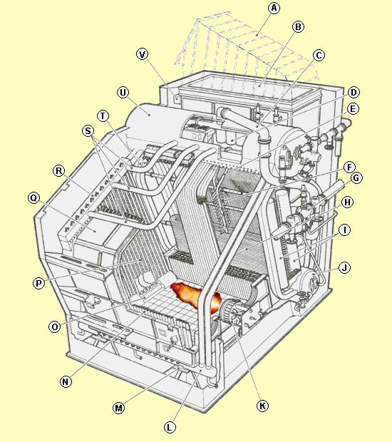
40 A. Smoke uptake B. Economizer A heat exchanger that transfers heat from Boiler Flue Gases to Boiler Feedwater. C. SteamOutlet Saturated steam from the SteamDrum to the Superheater D. Cyclone A device inside the drum that is used to prevent water and solids from passing over with the steamoutlet. E. Stay tube for superheater F. Stays for superheater tubes G. Superheated steam outlet H. Superheater A bank of tubes, in the exhaust gas duct after the boiler, used to heat the steam above the saturation temperature. I. Superheater Headers Distribution and collecting boxes for the superheater tubes. J. WaterDrum K. Burner L. Waterwall Header Distribution box for waterwall and downcomers. M. Foting N. Waterwall Tubes welded together to form a wall. O. Waterwall Header Distribution box for waterwall and downcomers. P. Back side waterwall Q. Boiler hood R. Waterwall Header Collecting box for waterwall and risers. S. Riser The water-steam emulsion rises in these tubes toward the steamdrum. T. Downcomer A tube through which water flows downward. These tubes are normally not heated, and the boiler water flows through them to supply the generating tubes. U. SteamDrum Separates the steam from the water. V. Economizer Header Distribution box for the economizer tubes.


41 Belleville water tube steam boiler The feedwater was fed into the to the feed water collector, at the lower end of the tubes, by means of an automatic feedwater controller. The heating surface in the boiler consists of a set of continuous tubes running to-and-fro over the furnace. The steam generated in the tubes passes upwards into the steam collector, carrying much water with it, but the water is separated by baffle plates in the steam collector drum. The carried over water returns to the water collector through vertical pipes, down-comers, at the ends of the steam collector. The water level height during full steam operation was about the middle of the water tube bank. The boiler's steam outlet was always provided with a pressure reducing valve that dried the steam since all remaining water evaporated at the lower pressure. Belleville boilers worked quite well at pressures between 12 and 16 bar, but false water level readings was a huge problem. Later boilers always had an economizer on the top. Eckrohr Steam Boilers

42 Eckrohr-Boiler (Corner Tube Boiler) is a boiler for all kinds of fuel. Originally it got its name because it has downcomers in the four corners. It is a natural water circulation single drum boiler and it needs no circulation pump. Downcomers, headers and waterwalls are welded together to a gas-tight tube cage. The Eck-rohr-Boiler is self-supporting and needs no supporting structure. It stands on its own downcomers. Due to the cage structure with downcomers, headers and overhead pipes the Eckrohr-Boiler is earthquake safe (more than 550 boilers installed in Japan, many of them for municipal waste).


43 The new Eckrohr marine steam boiler design This ERK boiler is designed to install on a tanker, which is used as utilities providing station for an offshore platform. boilers have been built. Eckrohr-Boilers are available as auxiliary boilers operating on oil or waste heat from the diesel engine. The weight of Eckrohr marine boilers is significantly low. The support structure on the ship is simple. The Eckrohr-Boiler configuration is particularly suited to marine duty as the water circulation is tolerant of high roll angles and will maintain safe water circulation at high inclination angles. More than 600 Eckrohr marine steam
.")
 to the steam space of the drum (6). The remaining mixture runs through mixture tube (3) into the drum.")
44 Eckrohr Boilers water and steam flow diagram 1. unheated return tubes 2. header 3. mixture tubes 4. riser tubes (evaporator) 5. overflow tubes 6. unheated steam drum 7. unheated downcomers The water-steam mixture flows upwards through the riser tubes (4). In the upper mixture tube (3) steam is already separated from water and a part of the water flows through unheated return tubes (1) to the header (2). The separated steam flows through the overflow tube (5) to the steam space of the drum (6). The remaining mixture runs through mixture tube (3) into the drum. The final separation of water and steam takes place in the drum, the water flows through the downcomers (7) to the headers (2). Exhaust gas boiler with extended heating surface


45 Waste heat recovery in motor ships A diesel engine loses approximately 30% of the energy to the exhaust gases. A turbocharger recover some of it, but there is still heat losses that can be recovered by means of an Exhaust Gas Boiler, EGB. Utilization of the energy in the exhaust gas is restricted due to risk of low temperature corrosion on the gas side of the tubes. The sulphuric acid dew point temperature is assumed to be at C. A temperature difference of 40 C must be considered in order to obtain a certain margin when the gas temperature decreases due to low load on the main engine. This means that an EGB shall not be designed to reduce the gas temperature at the EGB outlet below C at Continuous Service Rating. Besides, at gas temperatures below C, the vaporized unburned oil particles in the gas condense to an adhesive mixture of soot and oil resulting in troublesome deposits on the tubes and on the heating surface of the EGB. The reasonable optimal steam production of an EGB where no economizer is incorporated is consequently reached at a steam pressure of 3-4bar (saturated temperature C). In practice it is found that the pinch temperature shall be kept at minimum 25 C as a lower temperature difference will substantially increase the heating surface and the price of the EGB. An EGB is normally built to regenerate the heat from comparatively large flue gas quantities at a not very high temperature and with a limited pressure loss. To fulfill these demands, the boiler ought to be provided with tubes with extended surface on the gas-side. This can be achieved by means of pinned tubes, as in this example, or finned tubes. Scotch hybrid boilers Prud'Hon Capus and Howden-Johnson tried to improve the poor water circulation in the common Scotch fire-tube boilers by adding water tubes in a dry-back combustion chamber. It was claimed that this modification made them 10 per cent more efficient than conventional Scotch fire-tube marine boilers. Both types of boilers failed to make an impact despite of these advantages, the disadvantages of the hybrid arrangement being greater than the advantages. Prud'Hon Capus marine steam boiler


46 Thirty-two "Prud'Hon Capus" boilers were fitted onboard the cruise liner "Ile de France" in The operation pressure was 16 bar The red coil, to the right of the convection water-tubes, is the superheater. A Prud'Hon Capus marine steam boiler with the common dry-back combustion chamber open for service. Two fire-tubes and some of the convection water-tubes are visible on this picture.


47 Howden-Johnson marine steam boiler Three Howden-Johnson marine boilers were installed onboar T.S. Crispin in The operation pressure was 15 bar and the steam was superheated to 307 C The red coil, between the convection watertubes and the smoke tubes, is the superheater. The Howden-Johnson marine steam boiler without the common dry-back combustion chamber mounted. Part of the superheater is visible above the convection water-tubes
BOILERS CHAPTER 4. Fireroom The fireroom is a compartment containing boilers and the operating station for firing the boilers.
 CHAPTER 4 BOILERS The function of a boiler in the steam cycle is to convert water into steam. Reliability in operating naval boilers and associated equipment is important for the power plant to operate
CHAPTER 3 BASIC STEAM CYCLE
 CHAPTER 3 BASIC STEAM CYCLE To understand steam generation, you must know what happens to the steam after it leaves the boiler. A good way to learn the steam plant on your ship is to trace the path of
ASSSIGNMENT 3. Textbook Assignment: Boilers, chapter 4, pages 4-1 through 4-15, and Steam Turbines, chapter 5, pages 5-1 through 5-1.
 ASSSIGNMENT 3 Textbook Assignment: Boilers, chapter 4, pages 4-1 through 4-15, and Steam Turbines, chapter 5, pages 5-1 through 5-1. 3-1. What is the function of a boiler in the steam cycle? 1. To convert
Reactor-Boiler and Auxiliaries - Course 433 BOILER STEAM AND WATER SYSTEMS
 Lesson 433.60-1 Reactor-Boiler and Auxiliaries - Course 433 BOILER STEAM AND WATER SYSTEMS It was noted in an earlier lesson, that the reactor is a source of heat, and serves the purpose of a "furnace"
!!! Sample Written Program For Your Company. For BOILER SAFETY. Provided By:!!!
 Sample Written Program For Your Company For BOILER SAFETY Provided By: P.O. Box 2136 Slidell, LA 70458 Phone: 985-781-1444 Fax: 985-781-1446 Email: info@se-safety.com Purpose Boiler Safety Program The
Boiler Basics. Design and operation
 Boiler Basics Design and operation A boiler is an enclosed vessel that provides a means for combustion heat to be transferred into water until it becomes heated water or steam. The hot water or steam under
Boiler. Fire tube Boiler:
 Boiler What is Boiler? A closed metallic vessel in which the water is heated beyond the boiling temperature by the application of heat by the combustion of fuels to convert it into steam. The function
Boiler Mountings. Engr. Omar Sadath, Maritme Lecturer & Trainer, Bangladesh
 Boiler Mountings Engr. Omar Sadath, Maritme Lecturer & Trainer, Bangladesh overview Mountings are crucial without which the operation of boilers is unsafe. Proper maintenance and care of the mountings
9707 Key West Avenue, Suite 100 Rockville, MD Phone: Fax:
 9707 Key West Avenue, Suite 100 Rockville, MD 20850 Phone: 301-740-1421 Fax: 301-990-9771 E-Mail: awt@awt.org Part of the recertification process is to obtain Continuing Education Units (CEUs). One way
2. Sketch and describe a steam drum internal feedwater pipe. 3. Identify and describe a steam drum continuous blowdown line.
 Drum Internals Learning Outcome When you complete this module you will be able to: Describe drum internals. Learning Objectives Here is what you will be able to do when you complete each objective: 1.
MODEL ANSWER FOR ELEMENTS OF MECH.ENGG.(17413) 1) steam boiler- It is a closed vessel in which steam is produced from water by combustion of fuel.
 1) steam boiler- It is a closed vessel in which steam is produced from water by combustion of fuel.") MODEL ANSWER FOR ELEMENTS OF MECH.ENGG.(17413) Q 1. a) 1) steam boiler- It is a closed vessel in which steam is produced from water by combustion of fuel. 2) steam turbine- It is a device that extract
MODEL ANSWER FOR ELEMENTS OF MECH.ENGG.(17413) Q 1. a) 1) steam boiler- It is a closed vessel in which steam is produced from water by combustion of fuel. 2) steam turbine- It is a device that extract
Protective Chemistry for Steam Boiler Wet Layup posted to DPS client area on:
 Protective Chemistry for Steam Boiler Wet Layup posted to DPS client area on: May 29, 2014 Richard Kunz, DPS Consulting Chemist s treatment recommendation: sulfite = 100 ppm P alkalinity = 400 ppm 0.2
Document Code: 1 (15) Issuing date: Status:
 Issuing date: Status:") Document Code: 1 (15) Project : MULTI FUEL CFB BOILER SIMULATOR Author: Approved: Language: HSK Document title: SYSTEM DESCRIPTION BOILER WATER SYSTEM Submitted for: Customer reference: Other information:
Document Code: 1 (15) Project : MULTI FUEL CFB BOILER SIMULATOR Author: Approved: Language: HSK Document title: SYSTEM DESCRIPTION BOILER WATER SYSTEM Submitted for: Customer reference: Other information:
BASIC BOILERS NAME :- DATE :-
 BASIC BOILERS NAME :- DATE :- This examination was conducted under conditions that allowed a fair and honest test of the candidate s knowledge and ability. Exam supervisor C:\Tassie Steam\N01basicboiler
left filled with saltwater with the sea valves closed The steam pressure and volume will remain constant. critical end point
 13 1 D A bridge gage is normally used to determine turbine bearing oil clearance diaphragm tip blade axial clearance bearing wear clearance Coast Guard Regulations (46 CFR) requires machinery within the
There are two devices used together for heating crude oil in petroleum refinery as in figure (1), and these devices are:
, and these devices are:") Heating of Crude Oil 1.Introduction: There are two devices used together for heating crude oil in petroleum refinery as in figure (1), and these devices are: Heat Exchangers. Tube Still Heaters (Furnaces).
Heating of Crude Oil 1.Introduction: There are two devices used together for heating crude oil in petroleum refinery as in figure (1), and these devices are: Heat Exchangers. Tube Still Heaters (Furnaces).
Solution of I Mid Term Steam Engineering 6ME5A
 1(a) Discuss the working principle of LaMont high pressure boiler This boiler works on basic principle of forced convection. If the water is circulate by a pump inside the tube, the heat transfer rate
MECHANICAL SCIENCE Module 2 Heat Exchangers
 Department of Energy Fundamentals Handbook MECHANICAL SCIENCE Module 2 Heat Exchangers Heat Exchangers DOE-HDBK-1018/1-93 TABLE OF CONTENTS TABLE OF CONTENTS LIST OF FIGURES... ii LIST OF TABLES... iii
Efficient Steam System Design
 Efficient Steam System Design The word Efficient is often used to describe the general performance of a system. However it is important to distinguish between efficiency and effectiveness. Efficiency is
Fig.: macroscopic kinetic energy is an organized form of energy and is much more useful
 Harnessing Energy Fig.: macroscopic kinetic energy is an organized form of energy and is much more useful Vapor Power Cycle The vast majority of electrical generating plants are variations of vapor power
CHAPTER 6. HEATING PRODUCTION EQUIPMENT AND SYSTEMS
 CHAPTER 6. HEATING PRODUCTION EQUIPMENT AND SYSTEMS 6.1 Types of Heating Systems 6.2 Heating Energy Sources 6.3 Furnaces and Air Heaters 6.4 Boilers 6.5 District Heating 6.6 Selection of Medium- Steam
When you complete this module you will be able to: Describe various watertube boiler designs, including large generating units.
 Watertube Boilers Learning Outcome When you complete this module you will be able to: Describe various watertube boiler designs, including large generating units. Learning Objectives Here is what you will
CHAPTER 2: PROPERTIES OF STEAM AND STEAM POWER
 CHAPTER 2: PROPERTIES OF STEAM AND STEAM POWER Steam produced from water forms one of the most important working fluids in engineering energy conversion systems. The advantages of using steam (water) as
United States Coast Guard Marine Engineer Exam Questions Steam Knowledge
 BOOK Question Number Answer 13 1 D A bridge gage is normally used to determine turbine 13 2 B Coast Guard Regulations (46 CFR) requires machinery driving the fuel oil transfer and fuel oil service pumps
A hydronic system controls comfort by delivering heated or cooled fluid to the conditioned space through pipes.
 Introduction to Hydronics A hydronic system controls comfort by delivering heated or cooled fluid to the conditioned space through pipes. Hydronic heating systems use hot water or steam to deliver the
PIPE LINE IDENTIFICATION MARKINGS
 107 PIPING SYSTEMS The various pipe lines are the blood vessels of the power plant, for through them flow the vapors and liquids that are the life blood of the ship. MATERIALS Main Steam Line-The main
Math & Physics. Complete combustion requires an Air-FuelRatio of 14.7 to 1 for combustion.
 Plant OPS Math & Physics Complete combustion requires an Air-FuelRatio of 14.7 to 1 for combustion. Math & Physics Increasing oxygen levels by 9 to 15% improves boiler efficiency. Math & Physics Draft
AIM OF THE EXPERIMENT:- Study of boilers (fire tube, water tube) APPARATUS REQUIRED: - SL.NO NAME OF THE APPARATUS SPECIFICATION QUANTITY 01 Fire tube
 APPARATUS REQUIRED: - SL.NO NAME OF THE APPARATUS SPECIFICATION QUANTITY 01 Fire tube") LABORATORY MANUAL ON STUDY OF FIRE TUBE AND WATER TUBE BOILERS Prepared By Prof. (Dr.) M. K. Roul Professor and Principal, Gandhi Institute for Technological Advancement (GITA), Bhubaneswar 752054 June
LABORATORY MANUAL ON STUDY OF FIRE TUBE AND WATER TUBE BOILERS Prepared By Prof. (Dr.) M. K. Roul Professor and Principal, Gandhi Institute for Technological Advancement (GITA), Bhubaneswar 752054 June
Evaporation The process in which a liquid dissipates or emits vapor, fumes, or invisible minute particles.
 35 Evaporation of waste wash water occurs during normal operation of the pressure, steam or automatic vehicle wash system. It is generally assumed that 10-30% of wash water is lost to evaporation. Accelerated
CENTRIFUGAL PUMPS. STATE the purposes of the following centrifugal pump components:
 Pumps DOE-HDBK-1018/1-93 CENTRIFUGAL PUMPS CENTRIFUGAL PUMPS Centrifugal pumps are the most common type of pumps found in DOE facilities. Centrifugal pumps enjoy widespread application partly due to their
Heat Exchanger. The purpose may be either to remove heat from a fluid or to add heat to a fluid.
 HEAT EXCHANGERS Heat Exchanger Heat exchanger is an apparatus or an equipment in which the process of heating or cooling occurs. The heat is transferred from one fluid being heated to another fluid being
The equipment and materials shall be designed and constructed in accordance with the ASME code section I 2001 ED A02 and Chinese Standards.
 Steam Boiler Type S50-3.82/450 Traveling grate stoker 50t/h x 3.82 pa x 450 Degree C 1. Basic use of the boiler The boiler can be used for industrial power generation, or thermal power station for enterprises
Boiler Draft Equipment
 Boiler Draft Equipment Learning Outcome When you complete this module you will be able to: Discuss, sketch and describe the basic equipment used to supply combustion air to a boiler furnace. Learning Objectives
SECTION Boiler Controls & Waste Heat Recovery
 6 Boiler Controls & Waste Heat Recovery ARMSTRONG PRODUCT CATALOGUE 255 IGEMA BOILER LEVEL & TDS CONTROLS IGEMA offers boiler level and TDS control products of the highest quality standard, being certified
WHAT IS A BOILER? BOILER IS AN EQUIPMENT WHICH PRODUCES STEAM AT THE REQUIRED PRESSURE AND TEMPERATURE. BOILER DESIGN, MANUFACTURE & INSTALLATION ARE
 Your Logo Here TRAINING ON BOILERS PRESENTED AT M/S. MAGADI SODA COMPANY, MAGADI, KENYA LIMITED 1 WHAT IS A BOILER? BOILER IS AN EQUIPMENT WHICH PRODUCES STEAM AT THE REQUIRED PRESSURE AND TEMPERATURE.
ENERGY RECOVERY SOLUTIONS. Recover wasted energy to increase efficiency and save money immediately.
 ENERGY RECOVERY SOLUTIONS Recover wasted energy to increase efficiency and save money immediately. Cleaver-Brooks Engineered Boiler Systems Manufacturers of HRSGs, Waste Heat Recovery Units, and Waste
By Authority Of THE UNITED STATES OF AMERICA Legally Binding Document
 By Authority Of THE UNITED STATES OF AMERICA Legally Binding Document By the Authority Vested By Part 5 of the United States Code 552(a) and Part 1 of the Code of Regulations 51 the attached document has
SECTION 5 COMMERCIAL REFRIGERATION UNIT 21 EVAPORATORS AND THE REFRIGERATION SYSTEM UNIT OBJECTIVES 3/22/2012 REFRIGERATION
 SECTION 5 COMMERCIAL REFRIGERATION UNIT 21 EVAPORATORS AND THE REFRIGERATION SYSTEM UNIT OBJECTIVES After studying this unit, the reader should be able to Define high-, medium-, and low-temperature refrigeration.
Diocese of Cleveland Facilities Services Corporation
 Diocese of Cleveland Facilities Services Corporation BOILER MAINTENANCE and SERVICING SEASONAL MAINTENANCE - to be performed by trained boiler technician or boiler contractor only: 1. Disassemble the low
Volume 10 Summer Understanding Terminology Key to Treatment Program Success
 Volume 10 Summer 2003 Understanding Terminology Key to Treatment Program Success One of the keys to success of a boiler water treatment program is good communication between the water treatment professional
Optimizing Strategy for Boiler Drum Level Control
 Optimizing Strategy for Boiler Drum Level Control Avoid trips and maximize steam output by reviewing your control equipment, strategy, and tuning. Andrew W.R. Waite 06/18/2012 Inadequate control of drum
AIR CONDITIONING. Carrier Corporation 2002 Cat. No
 AIR CONDITIONING Carrier Corporation 2002 Cat. No. 020-016 1. This refresher course covers topics contained in the AIR CONDITIONING specialty section of the North American Technician Excellence (NATE)
AUTOMATION OF BOILERS USING LABVIEW
 I J L S C M 4(1), 2012, pp. 49-53 AUTOMATION OF BOILERS USING LABVIEW A. MICHAEL SIDDHARTHA AND S. NAVEEN KUMAR Under Graduate Student, Department of Electronics and Communication Engineering Thiagarajar
Attention is drawn to the following places, which may be of interest for search:
 CPC - F22B - 2017.02 F22B METHODS OF STEAM GENERATION; STEAM BOILERS (steam engine plants where engine aspects predominate F01K; domestic central-heating systems using steam F24D; heat exchange or heat
Thermal Fluid Heaters
 Thermal Fluid Heaters Vertical Coil, Vertical Tubeless, Electric and Horizontal Sizes from 75,000 to 40,000,000 BTU/HR The heat transfer innovators. THERMAL FLUID FEATURES AND BENEFITS KEY FEATURES No
Chapter 2.3: Steam System
 Part I: Objective type Questions and Answers Chapter 2.3: Steam System 1. For industrial process heating, the best quality of steam is: a) dry saturated steam b) superheated steam c) wet steam d) high
Speransa 2008: Round table: Nuclear and sustainable development Universitad Politecnica de Valencia \UPV - Passive safety systems -
 Universitad Politecnica de Valencia \UPV - Passive safety systems - complete+annex.doc 1 1.1 Definition of Passive Safety Systems...3 2. Passive safety systems for core decay heat removal....4 2.1 Pre-Pressurized
Document Code: 1 (13) Issuing date: Status:
 Issuing date: Status:") Document Code: 1 (13) Project : MULTI FUEL CFB BOILER SIMULATOR Author: Approved: Language: JJA Document title: SYSTEM DESCRIPTION REHEAT STEAM SYSTEM Submitted for: Customer reference: Other information:
Document Code: 1 (13) Project : MULTI FUEL CFB BOILER SIMULATOR Author: Approved: Language: JJA Document title: SYSTEM DESCRIPTION REHEAT STEAM SYSTEM Submitted for: Customer reference: Other information:
PIPING SYSTEM EQUIPMENTS
 PIPING SYSTEM EQUIPMENTS Introduction Equipments are devices that provide power, process and store materials. Equipments in piping systems depend on the specific industries using them. Specialized equipment
THE ALLIANCE FOR BANGLADESH WORKER SAFETY BOILER SAFETY
 THE ALLIANCE FOR BANGLADESH WORKER SAFETY BOILER SAFETY 1 Boiler Room Hazards A Risk Of Explosion Exists High Pressure steam Combustion Gases Chemicals Moving Machinery Hot Surfaces www.bangladeshworkersafety.org
ClearFire. Startup Guide. Model CFH. Horizontal Steam Boiler
 ClearFire Model CFH Horizontal Steam Boiler Startup Guide 750-293 www.cleaverbrooks.com Improper installation, adjustment, service, or maintenance can cause equipment damage, personal injury, or death.
Jet Compressors. Circulate Steam Boost Low-Pressure Steam Compress and Mix Gases in Desired Proportion
 s Circulate Steam Boost Low- Steam Compress and Mix Gases in Desired Proportion S&K s are used in the process, paper, petroleum, power, gas, and other industries to circulate steam, boost low-pressure
Steam The Primary Force
 HOW POWER PLANTS WORK Lesson One Steam The Primary Force 11101 4 Lesson 1 Steam The Primary Force TOPICS Energy for Power Plants Converting Energy to Electricity The Importance of Air in Combustion Removing
CHP-turbine room. CHP can capture almost EXTRACTED STEAM 20 PSI HIGH-PRESSURE STEAM 1250 PSI HEAT EXCHANGER HOT WATER SUPPLY F
 5 6 HIGH-PRESSURE STEAM is routed from the wood-chp boiler to the turbine. TURBINE BLADES spin at nearly 00 revolutions per second. Steam acting on the turbine blades creates mechanical energy in the TURBINE.
ROTARY DRYER CONSTRUCTION
 ROTARY DRYER The Rotary Dryer is a type of industrial dryer employed to reduce or to minimize the liquid moisture content of the material it is handling by bringing it into direct contact with a heated
Series 300 VTB. Installation Instructions
 Series 300 VTB Installation Instructions Sizes 7 12 16 20 30 HP #2 Fuel Oil Gas (500 to 2500 BTU) Gas Light Oil Combination High Pressure Steam Sizes 7 thru 16 HP (125 PSI) Sizes 20 and 30 HP (150 PSI)
PESIT-Bangalore South Campus
 USN PESIT Bangalore South Campus Hosur road, 1km before Electronic City, Bengaluru -560-100 Department of Mechanical Engineering INTERNAL ASSESSMENT TEST 2 Date : 03/04/2018 Max Marks : 50 Subject & Code
USER S INFORMATION MANUAL
 USER S INFORMATION MANUAL HOT WATER HEATING BOILERS DOMESTIC WATER HEATERS 150,000-300,000 Btu/hr MODELS EB-EWU-02 IMPORTANT INSTALLER - AFFIX INSTALLATION MANUAL ADJACENT TO THE BOILER CONSUMER - RETAIN
MAIN PROPULSION PLANT. DD445 and 692 CLASSES AND CONVERTED TYPES
 Main Propulsion Plant DD445 and 692 Classes and Converted Types, Operation Manual Folks, Main Propulsion Plant DD445 and 692 Classes and Converted Types, Operation Manual, Revision 1, Jan 1946 was created
Annex A-8 CONCENTRATED SOLAR POWER UNITS INDEX TO SYSTEM/COMPONENT CAUSE CODES
 Annex A-8 CONCENTRATED SOLAR POWER UNITS INDEX TO SYSTEM/COMPONENT CAUSE CODES SOLAR ENERGY GATHERING EQUIPMENT Solar Field 6500-6559 Thermal Storage 6570-6589 Operational Problems 6590-6599 STEAM TURBINE
The Condensate Water Systems
 The Condensate Water Systems Condenser: A closed vessel in which steam is condensed by abstracting the heat and where the pressure is maintained below atmospheric pressure is known as a condenser. The
Service Step by Step Trouble-Shooting Check-List
 WARNING: Only Data Aire trained technician or experience technicians should be working on Data Aire Equipment. Protect yourself at all times and work safe. Date: Dates at the job site: From: to Job#: Serial#:
Boiler Condensate Return Basics. Presented by Steve Connor February 24, 2016
 Boiler Condensate Return Basics Presented by Steve Connor February 24, 2016 What We Are Covering Today? Brief review of the total steam system Why a proper condensate return system is so important Condensate
Heat Reclaim. Benefits,Methods, & Troubleshooting By Dave Demma, Manager Supermarket Sales, Sporlan Division - Parker Hannifin Corporation
 Form 30-217 / January 2007 Heat Reclaim Benefits,Methods, & Troubleshooting By Dave Demma, Manager Supermarket Sales, Sporlan Division - Parker Hannifin Corporation While the vapor-compression cycle has
INSTALLATION, OPERATION AND MAINTENANCE. Ariterm Vedo
 INSTALLATION, OPERATION AND MAINTENANCE Ariterm Vedo CONTENTS General...3 Installation...4-5 Laddomat 21 Connection diagram...6 Temperature control valve...7 About burning wood...8 Operation...9-11 Service
ANNEX 6. Refinery No. 1 New Area. Problems Existing in the Current Condensate Return System of the New Area of Refinery No.1
 ANNEX 6 In FP the project was divided in two phases, but due to financial difficulties, Phase II is still not implemented. Below is what happened in Phase I of the Project, which will be replicated in
FUEL-FIRED VERTICAL TUBELESS BOILERS
 FUEL-FIRED VERTICAL TUBELESS BOILERS 4 60 P orizontal and Vertical Feedwater / Condensate Return Systems and Blow-down Tanks FULTON FUEL-FIRED VERTICAL TUBELESS BOILERS FULTON: AN INDUSTRY LEADER SINCE
Sootblowers. Learning Outcome. Learning Objectives. When you complete this module you will be able to: Discuss sootblowers.
 Sootblowers Learning Outcome When you complete this module you will be able to: Discuss sootblowers. Learning Objectives Here is what you will be able to do when you complete each objective: 1. Describe
Study and Design Considerations of HRSG Evaporators in Fast Start Combined Cycle Plants. Govind Rengarajan, P.E.CEM, Dan Taylor
 Study and Design Considerations of HRSG Evaporators in Fast Start Combined Cycle Plants Govind Rengarajan, P.E.CEM, Dan Taylor CMI Energy, Erie PA 1651 Bernd Pankow P.E, Pankow Engineering Abstract Combined
Importance of a Draught Regulator
 Importance of a Draught Regulator The purpose of a chimney (stack) is to generate a draught (draft) that will transport smoke and fumes away from the point of combustion. The chimney design and arrangement
MECHANICAL ENGINEERING ME.2017 FUNDAMENTAL OF REFRIGERATION AND AIR CONDITIONING. Sample Questions and Answers
 MECHANICAL ENGINEERING ME.2017 FUNDAMENTAL OF REFRIGERATION AND AIR CONDITIONING Sample Questions and Answers CHAPTER 5 EVAPORATORS 1. What is Evaporator? Classify the various types of evaporator. Evaporator
Presentation On Industrial Boiler Operation And Maintenance
 Presentation On Industrial Boiler Operation And Maintenance Supervised By: Engr. Poresh Kanti Das GM-MAL RIP, Mulgoan, Kaligonj, Gajipur Boiler fundamental. Assessment On Heat recovery Boiler. Boiler Operation.
B. A. T. Basic Appliance Training
 B. A. T. Basic Appliance Training BASIC REFRIGERATION presented by Phil Whitehead Program Objective The objective of this program is to give you some of the basic elements that are essential to understanding
Chapter 11. Design of Other BOP
 Nuclear Systems Design Chapter 11. Design of Other BOP Prof. Hee Cheon NO 11.1 Condenser Design 11.1.1 Consider Performance Requirements Accepting heat rejected by steam cycle as final heat sink Maintaining
1998 Expedition/Navigator Workshop Manual
 Page 1 of 8 SECTION 412-00: Climate Control System - General Information 1998 Expedition/Navigator Workshop Manual DESCRIPTION AND OPERATION Procedure revision date: 02/11/2000 Climate Control System WARNING:
Module 5: Combustion Technology. Lecture 38: Combustion Burners
 1 P age Module 5: Combustion Technology Lecture 38: Combustion Burners 2 P age Keywords : Atmospheric burner, atomizer, rotating cup burner, swirl type burner, nozzle design 5.7 Combustion Burners Types
WELCOME TO THE AWT REGIONAL TRAINING PROGRAM
 WELCOME TO THE AWT REGIONAL TRAINING PROGRAM 2014 Las Vegas and Indianapolis 2 Course Schedule Day 2 8:00 a.m. Time & Relationship Management 9:00 a.m. Filtration & Pretreatment 10:00 a.m. BREAK 10:15
Fuel-Fired Vertical Tubeless Boilers
 Fuel-Fired Vertical Tubeless Boilers Fulton Classic (4-60P), The EDGE (6-30P) orizontal and Vertical Feedwater / Condensate Return Systems and Blow-down Separators FULTON FUEL-FIRED VERTICAL TUBELESS BOILERS
Efficiency and Design Improvements in Multiple Hearth & Fluid Bed Incinerators
 Efficiency and Design Improvements in Multiple Hearth & Fluid Bed Incinerators CBE Chavond-Barry Engineering 400 Rt. 518, Blawenburg, NJ 08504 Outline Fluid Bed Incinerators (FBI s) - Reversible Bed Resizing
CONSIDERATIONS IN CONVERTING A DUAL SHELL OR A DUAL PRESSURE COAL FIRED PLANT CONDENSER INTO A COMBINED CYCLE PLANT CONDENSER
 Proceedings of the ASME 2013 Power Conference POWER2013 July 29-August 1, 2013, Boston, Massachusetts, USA POWER2013-98062 CONSIDERATIONS IN CONVERTING A DUAL SHELL OR A DUAL PRESSURE COAL FIRED PLANT
Steam Contamination - Causes & Cures
 ImproChem Technobrief Steam Contamination - Causes & Cures A business of Water & Process A basic objective in boiler operation is to keep the steam clean and dry. Contamination with boiler water impurities
Thomas J Kelly. Fundamentals of Refrigeration. Sr. Engineering Instructor Carrier Corporation. August 20, Page number: 1.
 Thomas J Kelly Sr. Engineering Instructor Carrier Corporation August 20, 2003 1 SESSION OBJECTIVES At the conclusion of this session you should be able to: 1. Describe the basics principles of refrigeration
Climate Control System
 Page 1 of 13 SECTION 412-00: Climate Control System General Information DESCRIPTION AND OPERATION 1998 Mark VIII Workshop Manual Climate Control System Cautions and Warnings WARNING: To avoid accidental
Evaporation System: Types and Design Aspects
 Evaporation System: Types and Design Aspects Dr. Pankaj Kumar, Er. Dhritiman Saha and Er. Chandan Solanki Food Grains and Oil Seeds Processing Division, ICAR-CIPHET, Ludhiana Evaporation is an important
HEAT GENERATION 1.01 RELATED CORNELL DESIGN AND CONSTRUCTION STANDARDS. B. Section HVAC Basic Materials and Methods
 230520 HEAT GENERATION Cornell s Design and Construction Standards provide mandatory design constraints and acceptable or required products for all construction at Cornell University. These standards are
ecodry Figure 1 - Process Diagram ecodry B General Process Description
 ecodry The process principal of the ecodry system is centered around the concept of drying in a closed steam loop, with a process-integrated thermal oxidation. The separation of flue gas from the drying
Installation, Operation and Maintenance LOK-FLANGE Multitube Heat Exchangers
 Bulletin 1200/4 (Revised 5/12) Installation, Operation and Maintenance LOK-FLANGE Multitube Heat Exchangers INNOVATORS IN HEAT TRANSFER I. INSTALLATION OF HEAT EXCHANGERS A. HEAT EXCHANGER SETTINGS 1)
Glossary. Carbon Dioxide (CO 2
 Glossary AFUE (Annualized Fuel Utilization Efficiency): A measure of the efficiency of the heating unit (burner and boiler/ furnace) including standby losses during the off-cycles, given on an annual basis.
How about Savings in Time, Money, Energy and Longer Life?
 Chapter 17: The Value of Maintaining Evaporative Cooling Equipment 97 The Value 17 of Maintaining Evaporative Cooling Equipment 1. Cooling Tower Maintenance and Upgrades... What s in it for You? How about
4 route 147, C.P.33 Coaticook, Qc J1A 2S8
 4 route 147, C.P.33 Coaticook, Qc J1A 2S8 TABLE OF CONTENTS INSTALLATION Nozzles p.3 Clearance for dismantling p.4 Foundations p.4 Foundation bolts p.5 Leveling p.5 Bolted joints p.5 Recommended bolt tightening
Improved Dryer Control
 Improved Dryer Control Kenneth C. Hill President Kadant Johnson Systems Division David Vijh Senior Process Control Engineer Technical White Paper Series EXECUTIVE SUMMARY Significant improvements in dryer
SULPHUR RECOVERY UNIT
 19 October 2015 SULPHUR RECOVERY UNIT START-UP CONSIDERATIONS SHRIKANT KOLI BLACK & VEATCH, MUMBAI Agenda - Burner Management System - Control Loops - Refractory Dry-Out - Start-up Experiences 2 Burner
FGR. Installation, Operation and Startup Instruction Manual FOR FLUE GAS RECIRCULATION SYSTEM. FGR-8 through FGR-22 (25 HP to 1000 HP)
") FGR Installation, Operation and Startup Instruction Manual FOR FLUE GAS RECIRCULATION SYSTEM FGR-8 through FGR-22 (25 HP to 1000 HP) Gas, Light Oil or Combination MANUFACTURED BY JOHN ZINK COMPANY, LLC
FGR Installation, Operation and Startup Instruction Manual FOR FLUE GAS RECIRCULATION SYSTEM FGR-8 through FGR-22 (25 HP to 1000 HP) Gas, Light Oil or Combination MANUFACTURED BY JOHN ZINK COMPANY, LLC
PACKAGED COMMERCIAL WATERTUBE BOILERS
 PACKAGED COMMERCIAL WATERTUBE BOILERS PACKAGED COMMERCIAL WATERTUBE BOILER American Boiler Manufacturers Association 4001 N. 9 th Street, Suite 226 Arlington, VA 22203-1900 703/522-7350 2003, American
US A United States Patent (19) 11 Patent Number: 6,092,490 Bairley et al. (45) Date of Patent: Jul. 25, 2000
 11 Patent Number: 6,092,490 Bairley et al. (45) Date of Patent: Jul. 25, 2000") US0060924.90A United States Patent (19) 11 Patent Number: 6,092,490 Bairley et al. (45) Date of Patent: Jul. 25, 2000 54) HEAT RECVERY STEAM GENERATR 4,858,562 8/1989 Arakawa et al.... 122/7 R 5,159,897
US0060924.90A United States Patent (19) 11 Patent Number: 6,092,490 Bairley et al. (45) Date of Patent: Jul. 25, 2000 54) HEAT RECVERY STEAM GENERATR 4,858,562 8/1989 Arakawa et al.... 122/7 R 5,159,897
Packaged Marine Design Thermal Fluid (Hot Oil) Heaters
 Heaters") PACKAGED MARINE THERMAL FLUID (HOT OIL) HEATERS Packaged Marine Design Thermal Fluid (Hot Oil) Heaters For Heating Asphalt Barges, Tankers, And Any Other Application Requiring Dependable Heating 13 Models
PACKAGED MARINE THERMAL FLUID (HOT OIL) HEATERS Packaged Marine Design Thermal Fluid (Hot Oil) Heaters For Heating Asphalt Barges, Tankers, And Any Other Application Requiring Dependable Heating 13 Models
Heating, Air Conditioning, Ventilation. Отопление-Кондиционеры-Вентиляция. MTM 8-30 kw UNIVERSAL OIL HEATER OPERATING MANUAL
 Heating, Air Conditioning, Ventilation Отопление-Кондиционеры-Вентиляция MTM 8-30 kw UNIVERSAL OIL HEATER OPERATING MANUAL 1. Usage MTM 8-30 universal oil heater is designed for heating commercial rooms
2x58 MW Coal Fired Power Plant at Mauritius
 2x58 MW Coal Fired Power Plant at Mauritius The coal-fired power plant produces electricity by the burning of coal and air in a Circulating Fluidized Bed Combustion Boiler (CFBC), where it heats water
Air Conditioning Clinic. Absorption Water Chillers One of the Equipment Series TRG-TRC011-EN
 Air Conditioning Clinic Absorption Water Chillers One of the Equipment Series TRG-TRC011-EN Absorption Water Chillers One of the Equipment Series A publication of The Trane Company Worldwide Applied Systems
LATTNER BOILER COMPANY 9.5 HP Low-NOx Installation and Start-Up Checklist for Dry Cleaners
 1 1. General Installation Information (to be completed by technician) Date installed: Location (city & state): Cleaner s name: National Board number (boiler): Installed by (company): Installed by (technician):