INSTALLATION, OPERATION & MAINTENANCE MANUAL ELECTRIC DUCT HEATER
|
|
|
- Moses Tate
- 5 years ago
- Views:
Transcription


1 , OPERATION & MAINTENANCE MANUAL ELECTRIC FOR COMMERCIAL INDOOR APPLICATIONS EH SERIES EK SERIES RENEWAIRE.COM
2 ELECTRIC ABOUT RENEWAIRE For over 30 years, RenewAire has been a pioneer in enhancing indoor air quality (IAQ) in commercial and residential buildings of every size. This is achieved while maximizing sustainability through our fifthgeneration, static-plate, enthalpic-core Energy Recovery Ventilators (ERVs) that optimize energy efficiency, lower capital costs via load reduction and decrease operational expenses by minimizing equipment needs, resulting in significant energy savings. Our ERVs are competitively priced, simple to install, easy to use and maintain and have a quick payback. They also enjoy the industry s best warranty with the lowest claims due to long-term reliability derived from innovative design practices, expert workmanship and Quick Response Manufacturing (QRM). TABLE OF CONTENTS Electric Duct Heater info Installation Start-up Maintenance As the pioneer of static-plate core technology in North America, RenewAire is the largest ERV producer in the USA. We re committed to sustainable manufacturing and lessening our environmental footprint, and to that end our Madison, WI plant is 100% powered by wind turbines. The facility is also one of the few buildings worldwide to be LEED and Green Globes certified, as well as having achieved ENERGY STAR Building status. In 2010, RenewAire joined the Soler & Palau (S&P) Ventilation Group in order to provide direct access to the latest in energy-efficient air-moving technologies. For more information, visit: renewaire.com. ELECTRIC INFO ELECTRIC CONFIGURATION CHART MODEL NUMBER RESTRICTIONS: 1 WIDTH INCHES ENTERED AS A WHOLE NUMBER. 2: HEIGHT INCHES ENTERED AS A WHOLE NUMBER. TYPE 1-2 "EH" = ELECTRIC ABOVE 20" HIGH X 40" WIDE (STANDARD) "EK "= ELECTRIC UP TO 20" HIGH X 40" WIDE WIDTH IN INCHES (SEE RESTRICTIONS 1&3) HEIGHT IN INCHES (SEE RESTRICTIONS 2&3) PILOT LIGHT "N" = NONE (STANDARD) "L"= LIGHT 24 TIME DELAY RELAY(SEE RESTRICTION 12) "-" = NONE (STANDARD) "R"= TIME DELAY RELAY 3: DENSITY SHOULD BE LESS THAN 22kW/ft² FOR TYPE "EH" AND LESS THAN 18kW/ft² FOR TYPE "EK". DENSITY= CAPACITY (kw) < 22 (W" x H")/144 4: CAPACITY kw ENTERED AS A WHOLE NUMBER. 5: FORMULAS FOR CALCULATING kw AND TEMPERATURE RISE: kw= CFM x ΔT 3150 MULTIPLE-CHOICE OR OPTIONAL FEATURES CAPACITY IN kw (SEE RESTRICTIONS 4&5) MOUNT "S"= SLIP IN (STANDARD) "F = FLANGED ELEMENT STYLE 12 "C" = OPEN COIL (STANDARD) CONTROL TYPE (SEE RESTRICTION 11) "D" = THERMOSTAT WITH SENSOR (STANDARD) "E" = ELECTRONIC STEP CONTROL "S" = SCR (FOR BAS SYSTEM) "V" = SCR WITH ANALOG SENSOR (0-10Vdc) 22 CONTROL VOLTAGE "S" = 24VAC (STANDARD) "1"= 120VAC ΔT = kw x 3150 CFM 6: NOT APPLICABLE. 7: VOLTAGE CODES "1" & "9" AVAILABLE WITH PHASE CODE "1" (SINGLE-PHASE) ONLY. 8: VOLTAGE CODES "4" & "8" AVAILABLE WITH PHASE CODE "3" (THREE-PHASE) ONLY. 9: POWER FUSING "F" REQUIRED WHEN AMPERAGE IS >48A. (BASED ON kw AND VOLTAGE) 21 STAGE (SEE RESTRICTION 10) 10: 4-STAGE FOR ELECTRONIC STEP CONTROL ONLY. ELEMENT MATERIAL 13 "C" = NI-CR-FE WITH NICKEL PLATE TERMINAL PINS (STANDARD) "A" = NI-CR WITH STAINLESS STEEL TERMINAL PINS "1" = SINGLE (STANDARD) "2" = 2-STAGE "4"= 4-STAGE 20 POWER FUSING (SEE RESTRICTION 9) "-" = NONE, "F"= FUSING 11: CONTROL TYPE "D" AVAILABLE WITH STAGE "1 AND "2" ONLY. CONTROL TYPE "E" AVAILABE WTIH STAGE "4" ONLY. CONTROL TYPE "S" & "V" AVAILABLE WITH STAGE "1" ONLY. UNLESS AMPERAGE IS GREATER THAN OR EQUAL TO 96A THEN STAGE "4" IS AUTOMATICALLY SELECTED. AIRFLOW ORIENTATION 14 "H" = HORIZONTAL (STANDARD) "V" = VERTICAL CONTROL BOX OFFSET 15 "L" = LEFT HAND (STANDARD) "R" = RIGHT HAND 19 PHASE "1" = SINGLE-PHASE, "3" = THREE-PHASE 18 VOLTAGE: (SEE RESTRICTIONS 7 & 8) "1" = 120V, "4" = 480V, "2" = 208V, "3"=240V, "8" = 600V, "9" = 277V 12: TIME DELAY RELAY "R" ONLY AVAILABLE WITH STAGE "2". NOTE: ALL S COME WITH STANDARD FEATURES: -DISCONNECT SWITCH -AIR FLOW SWITCH (NON ADJUSTABLE) -CONTROL TRANSFORMER CONTROL BOX RECESSED 16 "-" = NONE (STANDARD) "R" = RECESSED 1" 17 CONTROL BOX DUST TIGHT "-" = NONE (STANDARD) "D" = DUST TIGHT NOTE: DESCRIPTIONS OF FEATURE AND OPTIONS ARE FOUND IN THE AND OPERATION MANUAL 2 RENEWAIRE.COM, OPERATION AND MAINTENANCE MANUAL
3 ELECTRIC ELECTRIC INFO DEFINITIONS FOR CONFIGURATION CHART Heater Type: EK - heater up to 20" height and up to 40" width EH - heater above 20" height or above 40" width Width: W - Width of duct ID in inches. For slip-in type the W dimension is undersized by ¼" to allow heater to slip into ductwork. Range 8" - 99" Height: H - Height of duct ID in inches. For slip-in type the H dimension is undersized by 1/16" to allow heater to slip into ductwork. Range 8" - 99" Capacity: KW - Kilowatt rating of heater. Determined by airflow (CFM) and temperature rise (rt). Range KW Mount: Slip-in (Standard) - heater is installed through opening cut into side of duct and the control box is attached to duct. Flanged (Option) - heater is installed between two sections of flanged duct and bolted in place. Element Style: Open Coil (Standard) - open coil resistance wire. Used in most applications. Element Material: NI-CR-FE with nickel plate terminal pins (Standard) - standard C grade element wire. 60% nickel, 20% chromium, 20% iron NI-CR with stainless steel terminal pins (Option) - premium A grade element wire. 80% nickel, 20% chromium. Airflow Orientation: Horizontal (Standard) - heater installed where airflow in ductwork is horizontal through the heater. Vertical (Option) - heater installed where airflow in ductwork is vertical through the heater. Vertical up and down airflow available in EK series EH series - only approved for vertical up airflow. Control Box Offset: Left Hand (Standard) - the control panel is offset to the left side of the heating elements as determined when looking into the control box. Right Hand (Option) - the control panel is offset to the right side of the heating elements as determined when looking into the control box. Control Box Recessed (Option): Recessed 1" - Control box is designed to extend 1" beyond internally insulated duct. Heater element width construction is automatically reduced by 1". Heater element height construction is automatically reduced by 2". Recess depth dimension is 1". Only allowed for internally insulated ducts of 1" insulation thickness. Control Box Dust Tight (Option): Dust Tight - Compression type gasket installed on control box flanges to seal door opening. Control box seams are filled to prevent dust intrusion. Typically specified when local code requires it. Voltage and Phase: Single Phase - 120V, 208V, 240V, 277V 3-Phase - 208V, 240V, 480V, 600V Power Fusing: Required by UL and NEC if amperage is over 48A. Otherwise is an option. Stage: Single Stage (Standard) - All heating elements are energized simultaneously. SCR control is always single stage. 2-Stage (Option) - Heating capacity is divided into two sections. Half of the heating capacity can be energized when less heating is required. Both stages are energized when full heating is required. Can be for on/off control. 4-Stage - Heating capacity is divided into four sections. 4-stage for Electronic Step Control only. Control Voltage: 24 VAC (Standard) - secondary voltage 120 VAC (Option) - secondary voltage Control Type: Duct Thermostat with sensor - standard Definitions contiinued on page , OPERATION AND MAINTENANCE MANUAL RENEWAIRE.COM 3
4 ELECTRIC ELECTRIC INFO DEFINITIONS FOR CONFIGURATION CHART thermostat with on/off control. Sensor is duct mounted. Thermostat must be programmed by installer for the number of stages. (Standard) Electronic Step Control - provides sequencing control in steps of 4 for duct heater. Converts analog input signal into discrete steps or stages. As an example, if you have a 4-stage heater the step controller would be 4-stage. For an analog signal greater than 4Vdc the first stage would energize, for an analog signal greater than 6Vdc the first and second stages would energize, for an analog signal greater than 8Vdc the first, second, and third stages would energize, and for an analog signal at 10Vdc all stages would energize. Silicon Controlled Rectifier (SCR) - 100% step-less modulating control. Accepts 0-10Vdc or 4-20mA as control signal. Utilizes solid state relays (SSR) to switch current to the heating elements, on a time-proportioned basis. Silicon Controlled Rectifier (SCR) Vernier - When SCR control is selected and the heater is greater than 96A then an SCR vernier control is implemented. This combines an SCR with 4-stage electronic step control as a cost effective method for providing modulating control on heaters greater than 96A. An SSR is an electronic switching device similar to an electromechanical relay (contactor) but has no moving parts which allows very fast switching of high current loads without arcing or wearing out. A heater with an SCR controller must be installed in such a way as to provide good ventilation to the heat sink so that the life of the SSR is prolonged. Over-heating of an SSR causes it to fail so the heater must be installed such that the heat sink is positioned either vertically on the side of the control cabinet or on top of the control cabinet never on the bottom. Time Delay Relay (Option): Provides time delay of 30 to 60 seconds before energizing or deenergizing the circuit controlled. 24 VAC control voltage. Time delay relay available with 2-stage only. Pilot Light (Option): Light to indicate heater energized. Control voltage same as transformer secondary voltage (24 VAC or 120 VAC). Air Flow Switch: (Standard) Non-adjustable pressure switch that prevents the heater from being energized when no or very low air flow is present through the heater. Minimum air flow pressure is 0.05 in.w.c Auto Reset: (Standard) - Automatic reset limit switch for primary over-temperature protection. Required by UL. Manual Reset: (Standard) Manual reset limit switch for secondary over-temperature protection. Required by UL. Disconnect Switch: (Standard) Non-fused interlocking switch mounted in the door of the heater control box. Must be turned off to open door on control box. Interrupts power to the heater when turned off. Terminal Block: (Standard) Low voltage control terminal block included. Ground Lug: (Standard) Connection point for grounding field connected line voltage. All heaters are designed for zero clearance. Control box is constructed of galvanized steel. Control box has removable hinged access door with interlocking disconnect switch. All heaters are UL and cul listed and tested in accordance with Standard UL RENEWAIRE.COM, OPERATION AND MAINTENANCE MANUAL


 SCR (up to 96 Amps) SCR Vernier (over 96 Amps) Time delay relay")
5 ELECTRIC EK SERIES ELECTRIC SPECIFICATIONS Heater Type: Electric Duct Heater Typical KW Range: 1 60 kw Standard Features: A disconnecting magnetic control contactor per stage or each 48 Amp circuit within a stage Open-coil element Staged on/off Control terminal board Grounding lugs Automatic limit switch for primary overtemperature protection Manual reset limit switch for secondary overtemperature protection Non-adjustable airflow switch Standard control transformer - 24 VAC Disconnect switch Duct thermostat with sensor for on/off control (Ni/Cr/Fe) C Grade element wire with nickel-plated terminals Slip-in mount No left/right hand Vertical up/down flow Voltages & Phase: Single phase - 120, 208, 240, 277 Three phase - 208, 240, 480, 600 Control Voltage: 24 VAC Dimensions: Minimum - 8" x 8" (W x H) Maximum - 40" x 20" (W x H) Options: Flange mount (Ni/Cr) A Grade element wire with stainless steel terminals Recessed control box 1" Gasketed cover - dust tight Power fusing, standard for heaters drawing more than 48 Amps 2-stage 120 VAC transformer Electronic step controller (4-stage) SCR (up to 96 Amps) SCR Vernier (over 96 Amps) Time delay relay Pilot light Accessory: Room thermostat CAPACITY - kw EK SERIES CAPACITY SAFE OPERATING RANGE AIRFLOW - CFM Static Pressure Drop - Inches of Water PRESSURE DROP THROUGH Air Velocity - FPM (1, 2, 3 and 4 - the number of rows of heater coils) When the number of rows of heater coils is unknown, assume FLIPPABLE CAPABILITIES Unique to the EK series, this unit has the ability to flip 180. Additionally, EK heaters features both vertical up and vertical down airflow , OPERATION AND MAINTENANCE MANUAL RENEWAIRE.COM 5
6 EH SERIES ELECTRIC ELECTRIC SPECIFICATIONS Heater Type: Electric Duct Heater Typical KW Range: kw Standard Features: A disconnecting magnetic control contactor per stage or each 48 Amp circuit within a stage Open-coil element Staged on/off Control terminal board Grounding lugs Automatic limit switch for primary overtemperature protection Manual reset limit switch for secondary overtemperature protection Left hand offset control box Non-adjustable airflow switch Standard control transformer - 24 VAC Disconnect switch Duct thermostat with sensor for on/off control (Ni/Cr/Fe) C Grade element wire with nickel-plated terminals Slip-in mount Voltages & Phase: Single phase - 120, 208, 240, 277 Three phase - 208, 240, 480, 600 Control Voltage: 24 VAC Dimensions: Minimum - 40" x 20" (W x H) Maximum - 99" x 99" (W x H) Options: Flange mount (Ni/Cr) A Grade element wire with stainless steel terminals Recessed control box 1" Gasketed cover - dust tight Power fusing, standard for heaters drawing more than 48 Amps 2-stage 120 VAC transformer Electronic step controller (4-stage) SCR (up to 96 Amps) SCR Vernier (over 96 Amps) Pilot light Time delay relay Right hand offset control box Accessory: Room thermostat WATTS PER SQUARE FOOT, AREA 22,000 20,000 18,000 16,000 14,000 12,000 10,000 8,000 6,000 4,000 2,000 MINIMUM AIR VELOCITIES BELOW 78 F INLET AIR 78 TO 90 F INLET AIR 91 TO 110 F INLET AIR SAFE OPERATING RANGE Static Pressure Drop - Inches of Water PRESSURE DROP THROUGH Air Velocity - FPM (1, 2, 3 and 4 - the number of rows of heater coils) When the number of rows of heater coils is unknown, assume ,000 1,200 1,400 AIR VELOCITY - FPM BELOW 78ºF INLET AIR 78ºF TO 90ºF INLET AIR 91ºF TO 110ºF INLET AIR 6 RENEWAIRE.COM, OPERATION AND MAINTENANCE MANUAL
7 ELECTRIC ELECTRIC INFO PRO DIMENSIONS ELECTRIC OFFSET RIGHT OPTIONAL H F R W U T* M* Q* N BD* Z* F TYPE S SLIP-IN R U T* M* Q* N ABBREVIATIONS W Width H Height BD* Z* TYPE F FLANGE MOUNT H W * = Dimensions do not include allowance for control box cover. Control box cover will be larger than the control box. OFFSET LEFT STANDARD NOTES: 1. W and H determined by duct size A. For slip-in W = Duct width minus 1/4 inch H = Duct height minus 1/16 inch B. flange mount W and H=Duct size 2. U = (W+H Up to 60"=4 7/8), (61" and over U=6") (W greater than 36" U=6") 3. BD = 4 1/4, 6, 8 1/2, or 10 1/4 depth of control box depends on the components required and size of power entry holes 4. Z = (H+2" standard for slip in) (H+4" for flange mount) 5. T = 1" standard 6. M = 1" standard 7. Q = (12" minimum) Size depends on required components. Consult factory for dimensions 8. F = 9/16" for slip-in type 1" for flange mount 9. R = 1 1/2" when using 4 7/8" U dimension 15/16" when using 6" U dimension 10. N = Q minus R and U NOTE: R and N dimensional values exchange position for right hand offset , OPERATION AND MAINTENANCE MANUAL RENEWAIRE.COM 7
8 ELECTRIC PLANNING YOUR SIZING AN ELECTRIC An electric duct heater can be sized from the following information: Duct Width (W") and Duct Height (H") Heater voltage and phase Heater Capacity rating (kw) Or Design Air Flow (CFM) and Desired Temperature Rise (r F) AMPERAGE DRAW Any electric duct heater with line current over 48 amps automatically receives fusing per UL and NEC requirements. Electric duct heaters over 48 amps are subdivided into loads less than 48 amps. Formula for calculating line current are: Single Phase: Amps = Watts/Line Voltage Three Phase: Amps = Watts/(Line Voltage x 1.73) To convert kw to Watts multiply kw by 1000 KW AND TEMPERATURE RISE The following formula may be used to determine the approximate total kw required when the CFM (air volume) and desired temperature are known: kw = CFM x rt 3150 TEMPERATURE RISE The following formula may be used to determine the approximate temperature rise of a duct heater when the kw and CFM are known: rt = KW x 3150 CFM DETERMINING MAXIMUM KW Maximum Watts per Sq. In. of Duct Area Duct width (inches) x duct height (inches) = duct watts total sq. in. Max W = X w x duct area in 2 in 2 For EK, X = 125 w For EH, X = 156 w in 2 in 2 Maximum kw for Sq. Ft. of Duct Area Duct width (feet) x duct height (feet) = duct area total ft 2 Max W = X kw x duct area ft 2 ft 2 For EK, X = 18 kw ft 2 For EH, X = kw ft 2 8 RENEWAIRE.COM, OPERATION AND MAINTENANCE MANUAL
9 ELECTRIC MINIMUM AIR VELOCITIES - EH SERIES 22,000 MINIMUM AIR VELOCITIES The minimum uniform airflow in a duct heater is directly related to the inlet air temperature. Consideration must be given to both airflow across the heater and inlet air temperature, (shown at left). WATTS PER SQUARE FOOT, AREA 20,000 18,000 16,000 14,000 12,000 10,000 8,000 6,000 4,000 2,000 BELOW 78 F INLET AIR 78 TO 90 F INLET AIR 91 TO 110 F INLET AIR SAFE OPERATING RANGE 1. To calculate the watts per sq. ft. of duct area, divide the total watts required by the duct area. EXAMPLE: Duct Size = 2ft. x 3ft. Total watts = 20,000 W/Sq. Ft. = 20,000 = If the air handler equipment is expressed in FPM then a direct cross reference can be made by comparing the temperature of the air (as it enters the Duct Heater) to the KW rating on the chart of rated velocity. a. Draw a line horizontally from the Watts/Sq. Ft. required to the inlet air temperature being used. b. From this point of intersection on the Inlet Air Curve, draw a line down vertically to establish the air velocity. c. The velocity should never be lower than the velocity as determined from the chart. In cases where this is not true, the velocity must be increased or the KW required must be reduced. 3. In cases where the air handling equipment is expressed in CFM then convert to FPM by dividing the CFM by the duct area ,000 1,200 1,400 AIR VELOCITY - FPM EXAMPLE: FPM = CFM Duct Area BELOW 78ºF INLET AIR 78ºF TO 90ºF INLET AIR 91ºF TO 110ºF INLET AIR Note: Minimum airflow must be maintained at any point over the face of the heater Note: Observe at least one complete heating cycle to ensure that cycling of the safety limit controls does not occur before leaving the installation. PRESSURE DROP THROUGH EK SERIES CAPACITY Static Pressure Drop - Inches of Water Air Velocity - FPM (1, 2, 3 and 4 - the number of rows of heater coils) When the number of rows of heater coils is unknown, assume CAPACITY - kw SAFE OPERATING RANGE AIRFLOW - CFM , OPERATION AND MAINTENANCE MANUAL RENEWAIRE.COM 9
10 ELECTRIC PLANNING YOUR PLACEMENT OF THE ELECTRIC The information and instructions in this sheet apply to Duct Heater models for zero clearance installation in ducts. The Duct Heaters are approved for use Post ERVs with heat pumps, air conditioners, or other forced air systems. They may be controlled by contactors, relays, sequencers or solid state devices. The Duct Heaters are prewired, have voltage ratings to 600 volts, both single phase and three phase. The Duct Heaters are furnished with integral controls. CAUTION The air duct should be installed in accordance with the Standards of the National fire Protection Agency for the Installation of Air-Conditioning and Ventilating Systems (Pamphlet No. 90A) and Warm-Air Heating and Air- Conditioning Systems (Pamphlet No. 90B). CAUTION Do not Bank heaters (side by side).if greater capacity is required, proportion smaller heaters in separate runouts. CAUTION Heater control boxes must be completely accessible and located to provide ventilation at all times. GENERAL Inspect heater for any possible shipping damage. Check all insulators for breakage and inspect heater element wire for any deformation that could cause a short circuit or ground. Make sure all fasteners are tight. Electrical connections such as pressure terminals should be checked for tightness. For safe operation and best performance, the following installation procedures must be adhered to. Heaters may be installed in the sides of either horizontal or vertical ducts but never in the top or bottom of a horizontal duct. EH series heaters installed in vertical ducts are tested and approved for up airflow only! Vertical up and down airflow available in EK series. 1. Install a heater a minimum of (4) feet from heat pumps or central air conditioners at least 4 feet downstream from an air handler. 2. At least 2 feet either side of an elbow or turn. 3. At least 4 feet from any canvas duct connector or transition section for change in duct size. 4. At least 4 feet downstream from an air filter. 5. At least 4 feet upstream from a humidifier. Disclaimer Model EH and EK duct heaters offered by RenewAire are not to be installed in, on, or directly attached to any equipment and further must be installed according to the installation instructions shipped with each and every duct heater. Refer to Page 9 for: duct and air velocity requirements. 10 RENEWAIRE.COM, OPERATION AND MAINTENANCE MANUAL
11 AIRFLOW AIRFLOW UT DUC HE AT E S T UT C O DUC T HE AT E R S ELECTRIC & The DHD Duct series, Heaters which are are furnished with with integral a separate controls, control except panel fo for r the DD To remote & install DHD series, mounting. a which slip-in are furnished heater with Figure a separate F1, control cut panel an for opening, as required FRAME in the side of the duct. Slide heater in remote mounting. the Also duct s ee 06 using control Installation box Manual as Supplement template for to duct mark heaters the mounting screw holes. Remove unit and drill mounting that Also are s ee designed for -00 outdoor Installation installations. Manual Supplement for duct heaters holes. that are Mount designed unit for outdoor to duct installations. with sheet metal screws. Connect high and low voltage supplies along with fan interlock G E NE R AL: circuit (if no airflow switch is furnished). Larger heaters may require hangers. To could for install breakage cause a and short flange inspect circuit type heater or ground. element heater Make wire Figure sure for all any fasteners deformation F2, are insert tight. that heater between two sections of flanged HEATING ELEMENTS duct and bolt in Electrical could cause connections a short circuit such or as ground. pressure Make terminals sure all should fasteners be checked are tight. for ELEMENTS LED COPY place. tightness. Electrical IF For connections additional PRINTED" such as strength, pressure terminals the should duct be flange checked for should be doubled as shown in the figure. Large heaters tightness. TERMINAL OR T ALLAT ION may MANUAL INSrequire ALLAT ION: hanger straps. Connect high and low voltage supplies along with TERMINAL CONTROL fan interlock OR BOX circuit (if no For INSsafe T ALLAT operation ION: CONTROL BOX and best performance, the following installation airflow For safe operation switch and is best furnished). performance, the following installation O DUC T HE AT E R S eater rolled by lts, both fo r the DD el for ct heaters insulators ation that are tight. hecked for lation rtical ters ow only! ntral air section for The information and instructions in this sheet apply to Duct Heater models The information zero clearance and instructions installation this in sheet ducts. apply to Duct Heater models for zero clearance installation in ducts. The Duct Heaters are approved for use with heat pumps, air conditioners, The Duct Heaters or other are approved forced air for s use ystems. with They heat pumps, may be air controlled by contactors, conditioners, relays, or other sequencers forced air or ssolid ystems. state They devices. may be controlled by contactors, relays, sequencers or solid state devices. The Duct Heaters are prewired, have voltage ratings to 600 volts, both single The Duct phase Heaters and three are prewired, phase. have voltage ratings to 600 volts, both single phase and three phase. The Duct Heaters are furnished with integral controls, except fo r the DD Inspect G E NEheater R AL: for any possible shippi ng damage. Check all insulators for Inspect breakage heater and for inspect any possible heater shippi element ng wire damage. for any Check deformation all insulators that procedures must be adhered to. procedures must be adhered to. Heaters may be installed in the sides of either horizontal or vertical ducts Heaters but may never be installed the top in or the bottom sides of of either a horizontal horizontal duct. or Heaters vertical installed ducts but in never vertical in the ducts top are or bottom tested and of a approved horizontal for duct. up airflow Heaters only! installed in vertical ducts are tested and approved for up airflow only! 1.Install a heater a minimum of (4) feet from heat pumps or central air conditioners. 1.Install a heater a minimum of (4) feet from heat pumps or central air conditioners. 2. At least 4 feet downstream from an air handler. 2. At least 4 feet downstream from an air handler. 3. At least feet either side of an elbow or turn. 3. At least 2 feet either side of an elbow or turn. 4. At least feet from any canvas duct connector or transition section for change 4. At least in 4 duct feet size. from any canvas duct connector or transition section for change in duct size. WRAPPER 5. At FRAME least feet downstream from an air filter. 5. At least 4 feet downstream from an air filter. 6. At least feet upstream from humidifier. 6. At least 4 feet upstream from a humidifier. Refer to the back of this sheet for: duct, elec trical and air velocity requirements. Refer to the back of this sheet for: duct, elec trical and air velocity requirements. To install slip -in heater FIG.1, cut an opening, as required in the side To install a slip -in heater FIG.1, cut an opening, as required in the side of the duct. Slide heater in the duct using control box as template to of the duct. Slide heater in the duct using mark the mounting screw holes. Remove HEATING control box as template to unit and drill mounting holes. mark the mounting screw holes. Remove ELEMENTS unit and drill mounting holes. Mount unit to duct with sheet metal screws. Connect high and low Mount unit to duct with sheet metal screws. Connect high and low voltage supplies along with fan interlock circuit (if no airflow switch is voltage supplies along with fan interlock circuit (if no airflow switch is furnished). Larger heaters TERMINAL may require hangers. furnished). Larger heaters may require hangers. OR CONTROL BOX To To install install a flange flange type type heater heater FIG.2, FIG.2, Insert Insert heater heater between between two two sections sections of of flanged flanged duct duct and and bolt bolt in in place. place. For For additional additional strength, strength, the the duct duct flange flange should should be be doubled doubled as as shown shown in in the the figure. figure. Large Large heaters heaters may may require require hanger hanger straps. straps. Connect Connect high high and and low low voltage voltage supplies supplies along along with with fan fan interlock interlock circuit circuit (if (if no no airflow airflow sw sw itch itch is is furnished). furnished). F1 Slip-In Heater F2 Flange Heater See Figure F3 for examples of some common installation approaches (flippable EK series only). F3 INC. INC. Common Installation Approaches 500 GOULD DRIVE COOKEVILLE, TN TN FAX (931) PHONE (931) DOUBLE LIP "UNCONTROLLED COPY IF PRINTED" "UNCONTROLLED COPY IF PRINTED" INS T ALLAT ION MANUAL INS T ALLAT ION MANUAL HORIZONTAL & AIRFLOW & AIRFLOW WITH with HORIZONTAL BASE BASE FLIPPED 180 FLIPPED 180 FRAME DOUBLE DOUBLE LIP LIP FRAME FRAME HEATING HEATING HEATING ELEMENTS ELEMENTS TERMINAL OR TERMINAL OR CONTROL BOX CONTROL BOX VERTICAL & AIRFLOW VERTICAL & AIRFLOW REV. REV. D D E.C.O. E.C.O INSTRUCTIONS elocity FRAME SLIP-IN CONSTRUCTION SLIP-ON CONSTRUCTION SHOWN SHOWN AIR AIRFLOW n the side late to ting holes. d low switch is o sections duct flange require ith fan BASE INC. DRIVE COOKEVILLE, TN PHONE (931) AIRFLOW AIRFLOW TERMINAL OR CONTROL BOX BASE ROTATED HEATING ELEMENTS AIRFLOW AIRFLOW * ONE - 4 * ONE POSITIONS - 4 POSITIONS BASE * SAME SAME - FOR - FOR VERTICAL S VERTICAL S ELECTRICAL REQUIREMENTS REV. D E.C.O Refer to general wiring diagram on pages Each heater also has its specific wiring schematic label on the inside cover of the heater control box. 'W' 'H' AIRFLOW , OPERATION AND MAINTENANCE MANUAL RENEWAIRE.COM 11
12 ELECTRIC HEATING ELEMENT WIRING TYPICAL CONTACTOR POWER CIRCUITRY (Only power circuit shown, safety devices etc., omitted) DISCONNECTING TYPE: DISCONNECTING TYPE: SINGLE PHASE CONTACTOR SINGLE PHASE CONTACTOR SINGLE PHASE SUPPLY HEATING ELEMENTS SINGLE PHASE SUPPLY HEATING ELEMENT SINGLE LINE BREAK This type would be disconnecting for 120V and 277V, providing the contactor opens the ungrounded line. Heating elements, namely those used in three phase, balanced, configurations are factory wired, as manufacturers standard in two basic configurations delta or WYE. TWO LINE BREAK Heating power is completely disconnected by breaking both sides of the power source. All ungrounded power conductors are disconnected. THREE PHASE SINGLE PHASE SUPPLY CONTACTOR WYE All ungrounded conductors disconnected. Both WYE and Delta configurations shown. DELTA HEATING ELEMENT WIRING CONFIGURATIONS AND PROPERTIES SINGLE PHASE THREE PHASE LINE VOLTAGE HEATING ELEMENT(S) ll1 L1 480V 480V ll2 L2 L1 L2 480V 480V 480V ll2 ll1 L3 480V ll3 480V for illustration only L3 ll3 Element Voltage = Line Voltage THREE WIRE DELTA CONNECTION 1. Element Voltage = Line Voltage 2. Phase Currents In = ll1 = ll2 = ll3 3. Voltage measured between any two power legs (L1 to L2 etc.) should be equal to the three phase line voltage. THREE WIRE WYE CONNECTION 1. Element Voltage = Line Voltage Phase Currents In = ll1 = ll2 = ll3 3. Voltage measured between any two power legs (L1 to L2 etc.) should be equal to the three phase line voltage. 12 RENEWAIRE.COM, OPERATION AND MAINTENANCE MANUAL
13 ELECTRIC EK AND EH - SINGLE PHASE ON-OFF CONTROL WIRING WIRING SCHEMATICS EK AND EH - SINGLE PHASE SCR CONTROL WIRING , OPERATION AND MAINTENANCE MANUAL RENEWAIRE.COM 13
14 ELECTRIC WIRING SCHEMATICS EK AND EH - THREE PHASE ON-OFF CONTROL WIRING EK AND EH - THREE PHASE SCR CONTROL WIRING 14 RENEWAIRE.COM, OPERATION AND MAINTENANCE MANUAL
15 ELECTRIC LOW VOLTAGE CONTROL SYSTEM This heater is provided with a Class II 24 VAC power supply system that operates the unit s contactor(s). The 24 VAC Power Supply can also be used to power the externally-installed controls system. In the event of a short-circuit or overload, the transformer itself is designed to fail safely. SPECIFICATIONS Nominal Output Voltage under load: 24 VAC Typical Output Voltage at no load: 29-31V Minimum contact rating for connected control device: (50mA (1.2VA) INSTRUCTIONS CAUTION 1. Connect only to components intended for use with 24 VAC power. 2. Do not undersize the low-voltage wires connected to this device. Observe the wire length and gauge limits indicated in this manual. 3. Do not overload this unit s 24 VAC power supply system. Confirm that the power requirements of devices you connect to this power supply system do not exceed transformer available power. LIMITS OF POWER OUTPUT If limits on wire gauge and length are observed, you may connect control devices that draw up to 8VA to the provided terminals. More than one device can be connected as long as total steady-state load does not exceed transformer available power. OBSERVE THESE LIMITS TO WIRE LENGTH AND GAUGE in order to ensure reliable operation of the control system. Wire Gauge #22 #20 #18 #16 #14 #12 Circuit Length 100' 150' 250' 400' 700' 1000' Circuit Length is distance from Heater to Control Device. 1. Before servicing or cleaning the heater, switch power off at disconnect switch or service panel and lock-out/tag-out to prevent power from being switched on accidentally. More than one disconnect switch may be required to deenergize the equipment for servicing. 2. This installation manual shows the suggested installation method. Additional measures may be required by local codes and standards. WARNING RISK OF FIRE, ELECTRIC SHOCK, OR INJURY. OBSERVE ALL CODES AND THE FOLLOWING: 3. Installation work and electrical wiring must be done by qualified professional(s) in accordance with all applicable codes, standards and licensing requirements. 4. Any structural alterations necessary for installation must comply with all applicable building, health, and safety code requirements. 5. This heater must be grounded. 6. Use the heater only in the manner intended by the manufacturer. If you have questions, contact the manufacturer , OPERATION AND MAINTENANCE MANUAL RENEWAIRE.COM 15
16 ELECTRIC INSTRUCTIONS APPLICATION GUIDE A duct heater must be installed according to the installation instructions, wiring diagram and labeling supplied with the heater. Listed below are some important items when installing a electric duct heater: Never operate a duct F4 INC. heater without airflow. INC. The heater must always be interlocked with the ELECTRIC fan. This may be accomplished TROUBLESHOOTING by ELECTRIC GUIDE TROUBLESHOOTING GUIDE either an airflow switch or fan interlock relay. A A MUST BE MUST INSTALLED BE INSTALLED ACCORDING ACCORDING TO THE TO THE 2. INSTRUCTIONS, Never operate INSTRUCTIONS, heater WIRING WIRING DIAGRAM DIAGRAM AND LABELING AND LABELING SUPPLIED SUPPLIED WITH WITH THE THE.. without achieving at least the minimum airflow Listed below Listed are below some are important some important required. items items Always when when refer installing installing to a electric a duct electric heater: duct heater: the installation instructions 1. NEVER OPERATE and A the nameplate label WITHOUT 1. NEVER OPERATE to AIRFLOW. A WITHOUT AIRFLOW. The heater must determine always be your interlocked minimum with the The heater fan. must This always may air be be velocities accomplished interlocked based by with on either the an airflow fan. This switch may be or accomplished fan interlock relay. by either an airflow your inlet air temperature. switch or fan interlock relay. 2. NEVER OPERATE If the minimum WITHOUT airflow ACHIEVING AT LEAST THE MINIMUM AIRFLOW REQUIRED. 2. NEVER OPERATE requirements WITHOUT are ACHIEVING not present Always refer to the installation instructions and AT LEAST the THE nameplate MINIMUM the label heater AIRFLOW to determine will not REQUIRED. your function minimum Always refer air velocities to the installation based your instructions inlet air temperature. and F5 the nameplate properly and safely. (see F4) If the minimum label to determine airflow requirements your minimum are not air velocities present based the heater on your will inlet not function air temperature. properly and If the minimum safely. airflow (see 3. fig. Never requirements 1) operate the are heater not present the heater will with not function uneven airflow. properly The and safely. 3. (see NEVER fig. 1) OPERATE THE WITH UNEVEN AIRFLOW. minimum airflow requirements The minimum must airflow be requirements present at all must points be 3. NEVER OPERATE present at THE all points over the WITH heater UNEVEN face. AIRFLOW. over the heater face. (see F4) (see fig. 1) The minimum airflow requirements must be present 4. at THE all points AIR MUST 4. over The BE the air FILTERED. heater must be face. filtered. (see fig. 1) The incoming The air must incoming be free air from must all be debris, free combustible particles, and hazardous vapors. from all debris, combustible F6 4. THE AIR MUST BE FILTERED. 5. ALWAYS LOCATE particles, THE and hazardous AT LEAST 24" The incoming FROM air AN must ELBOW be OR free TURN. from all debris, combustible particles, vapors. and hazardous vapors. (see fig. 2) 5. ALWAYS LOCATE 5. THE Always locate AT LEAST the heater 24" FROM AN FROM ELBOW AN HEAT OR at TURN. PUMP least 24" OR CENTRAL from an AIR elbow (see fig. 2) CONDITIONER. or turn. (See F5) 6. ALWAYS LOCATE THE AT LEAST 48" (see fig. 3) EXAMPLE: IF 780 fpm IS REQUIRED 500 GOULD DRIVE COOKEVILLE, TN FAX (931) GOULD DRIVE PHONE COOKEVILLE, (931) TN fpm FAX (931) PHONE (931) fpm 780 fpm MIN. AIRFLOW AND EVEN AIR DISTRIBUTION ARE PRESENT EXAMPLE: IF 780 fpm IS REQUIRED EXAMPLE: EXAMPLE: IF 780 IF fpm 780 fpm IS IS REQUIRED 780 fpm 780 fpm 780 fpm 780 fpm MIN. MIN. AIRFLOW AIRFLOW AND AND EVEN EVEN AIR AIR 780 fpm MIN. DISTRIBUTION AIRFLOW ARE ARE PRESENT AND PRESENT 780 EVEN AIR fpm DISTRIBUTION ARE NOT PRESENT 500 fpm EXAMPLE: IF 780 fpm IS REQUIRED EXAMPLE: IF 780 fpm IS REQUIRED 780 fpm 780 fpm EXAMPLE: IF 780 fpm IS REQUIRED 780 fpm MIN. AIRFLOW AND EVEN AIR 780 fpm fpm DISTRIBUTION MIN. AIRFLOW ARE AND NOT EVEN PRESENT AIR fpm DISTRIBUTION ARE NOT PRESENT 500 fpm 470 fpm MIN. AIRFLOW IS NOT PRESENT EXAMPLE: IF 780 fpm IS REQUIRED 470 fpm EXAMPLE: IF 780 fpm 470 fpm IS REQUIRED 470 fpm FIG. 1 MIN. AIRFLOW IS NOT PRESENT 470 fpm MIN. AIRFLOW IS NOT PRESENT 470 fpm FIG. 1 HEAT PUMP OR AIR CONDITIONER HEAT PUMP OR AIR CONDITIONER 6. ALWAYS LOCATE 6. THE Always locate AT LEAST the heater 48" FIG ALWAYS LOCATE THE AT LEAST 48" FROM AN FROM HEAT ANY PUMP CANVAS OR CENTRAL at least 48" CONNECTOR AIR from an ERV, OR 48" MIN. 48" MIN. CONDITIONER. TRANSITION SECTION FOR CHANGE IN (see fig. 3) SIZE. heat pump or central air Note: An airflow switch only proves that airflow exists (a differential (see fig. 4) conditioner. (See F6) 7. ALWAYS LOCATE THE AT LEAST 48" in static pressure), not that the minimum air velocities and proper air FROM 8. ANY ALWAYS CANVAS LOCATE THE CONNECTOR AT LEAST OR 48" distribution for the duct heater exist. DOWNSTREAM FROM AN AIR HANDLER. TRANSITION SECTION FOR CHANGE IN (see fig. 5) SIZE. Note: All figures are showing a top view of a horizontal duct. (see fig. 9. 4) ALWAYS LOCATE THE AT LEAST 48" UPSTREAM FROM AN HUMIDIFIER. 8. ALWAYS (see LOCATE fig. 6) THE AT LEAST 48" FIG. 4 DOWNSTREAM FROM AN AIR HANDLER. NOTE: ALL FIGURES ARE SHOWING A TOP (see fig. 5) VIEW OF A HORZONTIAL. PAGE 1 OF 2 RENEWAIRE.COM, OPERATION AND MAINTENANCE MANUAL ALWAYS LOCATE THE AT LEAST 48" UPSTREAM FROM AN HUMIDIFIER. (see fig. 6) 24" MIN. FIG. 1 24" MIN. FIG. 2 48" MIN. FIG. 2 48" MIN. FIG. 3 48" MIN. 48" MIN. FIG. 4
17 ELECTRIC INSTRUCTIONS 7. Always locate the heater at least 48" from any canvas duct connector or transition section for change in duct size. If connecting to round duct, install heater in a rectangular duct section. Use roundto-rectangular pyramidal transitions to connect round duct to rectangular duct. Always locate the heater at least 48" from any transition section for change in duct size. Follow installation guidelines given in manual and in accordance with SMACNA guidelines (see F7) 0. ALWAYS LOCATE THE AT LEAST 48" DOWNSTREAM FROM AN AIR FILTER.. ALWAYS (see fig. 7) LOCATE THE AT LEAST 48" DOWNSTREAM FROM AN AIR FILTER.. ALWAYS 1. NEVER (see fig. INSTALL 7) LOCATE THE AT LEAST 48" 8. Always A STANDARD locate the heater INTO at A DOWNSTREAM FROM AN AIR FILTER. WITH AN INTERNAL OBSTRUCTION.. (see NEVER fig. 7) Due to the INSTALL fact that least A STANDARD an obstruction 48" downstream can block INTO from A airflow WITH at the AN temperature INTERNAL an air handler. limit OBSTRUCTION. controls (See F8) and. NEVER element Due to INSTALL the terminations. fact that A STANDARD an obstruction If this situation can exist, block INTO A it airflow WITH can be corrected at the AN temperature INTERNAL 9. Always by using limit OBSTRUCTION. locate a heater controls the with and heater a Due element to the recessed terminations. fact that an obstruction control box and If this reduced situation can block wrapper exist, size. it airflow can This be at situation corrected the temperature is common by least using limit 48" with a heater upstream controls internally with and a insulated from element recessed terminations. ducts. (see control fig. 8) an box humidifier. and If this reduced situation (See wrapper exist, it F9) size. can This be situation corrected is by common using a with heater internally with a insulated recessed 2. NEVER ducts. (see control INSULATE fig. 8) box and reduced wrapper size. 10. Always THE EXTERIOR locate the OF heater THE This situation is common with internally insulated CONTROL BOX.. ducts. NEVER (see The control INSULATE fig. 8) box must at THE least be EXTERIOR completely 48" downstream OF accessible THE and CONTROL located BOX. where from ventilation an air filter. can be (See provided F10) at. NEVER all The times. control INSULATE (see box fig. must THE 9) be EXTERIOR completely OF accessible THE CONTROL and located BOX. where ventilation can be provided at The 3. NEVER all times. control INSTALL (see box fig. must A 9) be completely accessible NEAR A DOUBLE and located where ventilation can be provided at BLOWER OUTLET.. all NEVER times. A heater INSTALL (see fig. must be A 9) installed far NEAR enough A DOUBLE away from a BLOWER double blower OUTLET. outlet that even and proper. NEVER airflow A heater INSTALL is must present be A installed or separate far NEAR duct enough A DOUBLE heaters away from BLOWER a placed double OUTLET. in blower the duct outlet runouts that of even each and blower. proper (all A airflow heater installation is must present be installed must conform or separate far enough with duct the heaters away from a placed double installation blower the instructions.) duct outlet runouts that even (see of each and fig. 10) blower. proper (all airflow installation is present must or conform separate with duct the heaters heater placed 4. installation in the NEVER INSTALL instructions.) duct runouts A (see of each LESS fig. blower. 10) (all THAN 48" installation must conform with the heater FROM ANY FAN.. installation NEVER Mounting INSTALL instructions.) a heater A any (see closer LESS fig. 10) than THAN 48" to 48" a fan will FROM result ANY in FAN. uneven airflow.. NEVER Mounting INSTALL a heater A any closer LESS than THAN 48" to 48" a fan FROM 5. ORDER will result ANY THE in FAN. uneven airflow. WITH THE FACTORY Mounting a heater any closer than 48" to a fan INSTALLED LINEAR TEMPERATURE LIMIT. will ORDER result CONTROL THE in uneven IF airflow. THE WITH WIDTH THE FACTORY > 72". INSTALLED LINEAR TEMPERATURE LIMIT. ORDER 6. NEVER CONTROL THE USE IF ALUMINUM THE WITH THE CONORS. WIDTH FACTORY > 72". INSTALLED LINEAR TEMPERATURE LIMIT Use copper conductors only for all incoming. CONTROL NEVER wiring. USE IF THE ALUMINUM CONORS. WIDTH > 72". Use copper conductors only for all incoming. NEVER 7. NEVER wiring. USE ALUMINUM CONORS. INSTALL A STANDARD Use copper conductors only for all incoming OUTDOORS WITHOUT MAKING SPECIAL. wiring. NEVER PROVISIONS INSTALL TO A PROTECT STANDARD THE OUTDOORS AND CONTROL WITHOUT BOX FROM MAKING THE SPECIAL ELEMENTS.. NEVER PROVISIONS INSTALL TO A PROTECT STANDARD THE OUTDOORS WITHOUT MAKING SPECIAL F7 F8 F9 F10 48" MIN. 48" MIN. 48" MIN. 48" MIN. 48" MIN. FIG. 5 FIG. 5 48" MIN. FIG. 5 48" MIN. 48" MIN. FIG. 6 FIG. 6 48" MIN. FIG. 6 48" MIN. 48" MIN. FIG. 7 W/ INTERNAL INSULATION FIG. 7 W/ INTERNAL FIG. 7 INSULATION W/ INTERNAL INSULATION AIR HANDLER AIR HANDLER AIR HANDLER HUMIDIFIER HUMIDIFIER HUMIDIFIER AIR FILTER AIR FILTER AIR FILTER FIG , OPERATION AND MAINTENANCE MANUAL RENEWAIRE.COM W/ EXTERNAL FIG. 8 INSULATION W/ EXTERNAL FIG. 8 INSULATION Continued on page
18 and and located located where where ventilation ventilation can can be be provided provided at at all times. (see fig. 9) all times. (see fig. 9) 13. NEVER INSTALL A NEAR DOUBLE 13. NEVER INSTALL A NEAR A DOUBLE BLOWER OUTLET. BLOWER A heater OUTLET. must be installed far enough away from A heater a double must blower be installed outlet that far even enough and proper away from a double airflow blower is present outlet or separate that even duct and heaters proper airflow placed is in present the duct or runouts separate of duct each heaters blower. (all placed installation the duct must runouts conform of with each the blower. heater (all installation must instructions.) conform with (see the fig. heater 10) installation instructions.) (see fig. 10) 14. NEVER INSTALL A LESS THAN 48" 14. NEVER FROM INSTALL ANY FAN. A LESS THAN 48" FROM Mounting ANY FAN. a heater 11. any Never closer install than a standard 48" to a fan Mounting will result a heater in uneven any airflow. heater closer into than a duct 48" with to a fan an will result in uneven airflow. 15. ORDER THE internal WITH obstruction. THE FACTORY Due to 15. ORDER INSTALLED THE LINEAR the WITH TEMPERATURE fact that THE an FACTORY obstruction LIMIT INSTALLED CONTROL LINEAR IF THE WIDTH > 72". can TEMPERATURE block airflow at LIMIT the CONTROL IF THE 16. NEVER USE ALUMINUM temperature WIDTH CONORS. limit > 72". controls Use copper conductors and element only for terminations. all incoming If 16. NEVER USE ALUMINUM CONORS. wiring. Use copper conductors this only situation for all exists, incoming it can be 17. wiring. NEVER INSTALL A corrected STANDARD by using a heater OUTDOORS WITHOUT with MAKING a recessed SPECIAL control box 17. NEVER PROVISIONS INSTALL TO A PROTECT STANDARD and reduced THE wrapper size. OUTDOORS AND CONTROL WITHOUT BOX MAKING FROM THE SPECIAL ELEMENTS. PROVISIONS TO PROTECT This situation THE is common 18. AND NEVER CONTROL BUNDLE, BOX TIE with FROM OR internally WRAP THE POWER ELEMENTS. insulated WIRING. The wire could overheat ducts. or (see the F11) insulation could 18. NEVER breakdown. BUNDLE, TIE OR WRAP POWER WIRING. The wire could overheat 12. Never or insulate the insulation the exterior could 19. breakdown. NEVER USE A DIFFERENT VOLTAGE AND/OR of the control box. The PHASE THAN WHAT IS LISTED ON THE 19. NEVER NAMEPLATE USE A DIFFERENT LABEL. control VOLTAGE box must be AND/OR PHASE The duct THAN heater WHAT is to completely IS be LISTED used only accessible ON at THE the and voltage NAMEPLATE and phase that LABEL. is listed on the nameplate label. located where ventilation The duct heater is to be used only at the voltage Note: An airflow switch can only be proves provided that at airflow all times. and phase that is listed on the nameplate label. exist (a differential in static (see F12) pressure), not that the minimum air velocities and proper air Note: An airflow switch only proves that airflow exist distribution for 13. the Never duct install heater a exist. (a differential in static pressure), not heater that near the minimum air velocities a double and proper blower air outlet. A distribution for the heater duct heater must be exist. installed far enough away from a double blower outlet that even and proper airflow is present or separate duct heaters placed in the duct runouts of each blower. (all installation must conform with the heater installation instructions.) (see F13) ELECTRIC 14. Never install a heater less than 48" from any fan. Mounting a heater any closer than 48" to a fan will result in uneven airflow. F11 F12 F13 FIG. 6 FIG. 6 48" MIN. 48" MIN. W/ INTERNAL INSULATION FIG. 7 W/ INTERNAL FIG. INSULATION 7 W/ INTERNAL INSULATION FIG. 8 FIG. 8 W/ EXTERNAL FIG. 8INSULATION FIG. 9 FIG. 10 NOTE: ALL FIGURES ARE SHOWING A TOP VIEW OF A HORZONTIAL. FIG. 10 AIR FILTER AIR FILTER W/ EXTERNAL INSULATION FIG. 9 NOTE: ALL FIGURES ARE SHOWING A TOP VIEW OF A HORZONTIAL. 15. Never use aluminum conductors. Use copper conductors only for all incoming wiring. 16. Never install a standard heater outdoors without making special provisions to protect the heater and control box from the elements. PAGE 2 OF 2 PAGE 2 OF Never bundle, tie or wrap power wiring. The wire could overheat or the insulation could breakdown. 18. Never use a different voltage and/or phase than what is listed on the heater nameplate label. The duct heater is to be used only at the voltage and phase that is listed on the nameplate label. 18 RENEWAIRE.COM, OPERATION AND MAINTENANCE MANUAL
19 ELECTRIC ACCESSORIES These heaters may be ordered with factory-supplied thermostats. NOTE: Installation details for Electric Duct Heaters equipped with SCR's or Electronic Step Controllers (Including SCR Vernier Control) This heater is designed to accept an analog control signal. The heater will need to be supplied with either a 0(2) to 10 VDC or a 4 to 20 ma signal INTERFACE MODULE CONTROL SIGNAL WIRING CONNECTION DIAGRAM A. Stand Alone Thermostat for Modulating Control: Use this schematic if thermostat requires 24 VAC power and is to be powered by the heater transformer. A CONTROL WIRING SCHEMATICS CAUTION This heater will NOT operate with a standard 24 VAC control signal. B. DDC BAS for Modulating Control (2-10Vdc): Use this schematic if the Building Automation System provides a 2-10 Vdc signal to control the heater. B CAUTION Do NOT adjust any dip switches on the controls within the heater! They are factory set-control. Signal is determined by interface module connection. C. DDC BAS for Modulating Control (4-20 ma): Use this schematic if the Building Automation System provides a 4-20 ma signal to control the heater. C , OPERATION AND MAINTENANCE MANUAL RENEWAIRE.COM 19
20 ELECTRIC CONTROL WIRING SCHEMATICS ELECTRONIC STEP CONTROLLER OR SCR CONTROL D. Viconics Room Thermostat without Remote Sensor for Modulating Control: Use this schematic if a Viconics thermostat without remote sensor is used to control the heater. D COMMON 3 24 VAC 4 0 TO 10 VDC 5 REMOTE SENSOR 6 Vdc PULSED 7 VICONICS C ROOM THERMOSTAT SIGNAL INTERFACE MODULE NOTE: DO NOT ADJUST DIP SWITCHES ON THERMOSTAT WITHOUT REMOTE SENSOR E. Viconics Room Thermostat with Remote Sensor for Modulating Control: Use this schematic if a Viconics thermostat with remote sensor is used to control the heater. E COMMON 24 VAC 0 TO 10 VDC REMOTE SENSOR Vdc PULSED SIGNAL INTERFACE MODULE VICONICS C ROOM THERMOSTAT 4 ROOM THERMOSTAT DIP SWITCH SETTINGS SWITCH S1 S2 SETTING 1 0 VICONICS S61 REMOTE SENSOR WITH REMOTE SENSOR 20 RENEWAIRE.COM, OPERATION AND MAINTENANCE MANUAL
21 ELECTRIC START-UP ELECTRICAL REQUIREMENTS Refer to attached wiring diagram and wiring diagram on inside of cover. Make sure line and control voltage of system matches that noted on wiring diagram. Wire in accordance with N.E.C. and any existing local codes. Check tightness of all factory and field electrical connections. Make sure fan interlock is wired in if the Heater does not have an air flow switch. Use 90 deg. C (194 deg. F) copper wire. Control must be wired for N.E.C. Class 1 unless otherwise specified. When Heater has integral transformer for control voltage to thermostat, use thermostat with isolating contacts to prevent interconnection of Class 2 outputs. Disconnect all electrical power before servicing. When servicing heater, make sure all components are repositioned in the proper location and reconnect per wiring diagram. Replacement parts must be identical to the original components. Contact factory for replacement parts. COMMISSIONING GENERAL OPERATING REQUIREMENTS Minimum Air Velocity: 70 CFM per KW (75-80 Recommended) Maximum Inlet Air Temp: 100 Deg. F Maximum Heater KW: 18 KW per square foot of duct cross section (EK-series) 22 KW per square foot of duct cross section (EH-series) Most models may be flipped and rotated. Note: Minimum air flow or greater must be maintained uniformly over the entire face of the heater. The velocity of air should NEVER be lower than the specified minimum. In cases where this is not true the KW must be reduced or the velocity of air increased. Note: Observe at least one Heating cycle to ensure that cycling of safety limit controls does not occur under normal operating conditions before leaving the installation. WARNING This electric duct heater is intended for heating general ventilation air only. Do not use in airstreams containing hazardous or explosive materials or vapors. Note: The air temperature entering the duct heater should not exceed those marked on the heater nameplate label , OPERATION AND MAINTENANCE MANUAL RENEWAIRE.COM 21
22 ELECTRIC MAINTENANCE SERVICE PARTS Electric Duct Heater 22 RENEWAIRE.COM, OPERATION AND MAINTENANCE MANUAL
23 ELECTRIC MAINTENANCE All RenewAire heaters are designed to be maintenance free and operate for a long time without problems. The following are a few steps that are recommended: 1. Periodic inspection of the heater to check for any accumulation of dust on heating elements, any signs of rusting in the control panel and to check for any heater frame damage due to over heating. 2. Periodic inspection of the following heater components (during and before heating season): a. All fuses b. Resistance from phase to phase for each circuit c. Electrical connections to all contactors and heating elements d. All contactors e. Step controllers and modulating valves (SCR) REQUIREMENTS WARNING DO NOT ATTEMPT TO CLEAN OR SERVICE WITHOUT DISCONNECTING ALL SOURCES OF POWER 3. Always replace defective components with original parts. Contact factory for replacement parts , OPERATION AND MAINTENANCE MANUAL RENEWAIRE.COM 23

24 UNMATCHED VENTILATION SUPPORT As much as our unsurpassed quality and performance, our customers can also depend on our professional support staff for swift, professional assistance with all their technical, application, and service needs. Every time. Anywhere. At RenewAire unlike other ventilation suppliers advanced ventilation solutions are all we do. Our sole passion. Which is why for all commercial projects, we are the V in HVAC... and the only name you need to know. USA (800) FAX: (608) HELGESEN DRIVE MADISON, WISCONSIN USA CANADA (905) FAX: (905) MEXICO, CENTRAL &SOUTH AMERICA 52 (222) FAX: 52 (222) _001 (02/17)
HEATER E L E CT R I C DUCT RENEWAIRE EVERYWHERE EVERY GEOGRAPHY, EVERY CLIMATE, EVERY HOME, EVERY BUILDING AND EVERY APPLICATION
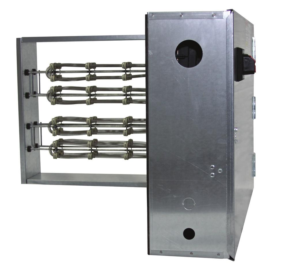
 E L E CT R I C DUCT HEATER FLIPPABLE SHOWN RENEWAIRE ERV + ELECTRIC DUCT HEATER: A SINGLE-SOURCE SOLUTION RENEWAIRE EVERYWHERE EVERY GEOGRAPHY, EVERY CLIMATE, EVERY HOME, EVERY BUILDING AND EVERY APPLICATION
INSTALLATION, OPERATION & MAINTENANCE MANUAL ELECTRIC DUCT HEATER
 , OPERATION & MAINTENANCE MANUAL FOR COMMERCIAL INDOOR APPLICATIONS EK SERIES RENEWAIRE.COM ABOUT RENEWAIRE For over 30 years, RenewAire has been a pioneer in enhancing indoor air quality (IAQ) in commercial
Electric Duct Heaters. IDHB & IDHC Series
 Electric Duct Heaters IDHB & IDHC Series May 2014 1 Duct Heaters Greenheck has a complete line of configurable electric duct heaters that are perfectly suited to your HVAC application. Our CAPS configuration
Electric Duct Heaters
 Electric Duct Heaters 12541_Tutco_Catalog.indd 1 3/4/11 8:46:01 AM TYPICAL HEATER CONSTRUCTION TUTCO, the world s largest supplier of open coil heating elements, produces the highest quality products in
TUTCO Inc. E Series Electric Single Duct VAV / Duct Heater Installation Instructions Heater Models EVH, ERH, EDH & RHE
 General for All Models TUTCO Inc. E Series Electric Single Duct VAV / Duct Heater Installation Instructions Heater Models EVH, ERH, EDH & RHE Inspect heater for any possible damage. Check all insulators
Electric Coils. Blower Coils. Product Information
 Product Information General Information Electric heat coils are an available accessory for use with Price blower coil units. The electric heating coils have been specific ally designed to suit Price blower
Standard Duct Heaters Open Coil
 HUA Slip-In and HUP Flanged Heaters The 80% Rule HEATREX recommends the heater should occupy at least 80% of the actual inside area of the duct, as shown in Figure 45. Only small amounts of air will bypass
Duct Heaters volts/1 phase volts/3 phase volts/3 phases volts/3 phases. Flange Type Duct Heater.
 Duct Heaters Synheat duct heaters come in various sizes and dimensions to fit any compartment. There are three types of duct heaters available: open coil, tubular element or finned tubular heating elements
Bulletin A Brasch Manufacturing Co., Inc.
 Bulletin A102-1 Brasch Manufacturing Co., Inc. Index Bottom Insert.................... 11 Raintight Construction.............. 11 Bottom Outlet.................... 12 Recessed Terminal Box..............
READ AND SAVE THESE INSTALLATION INSTRUCTIONS
 Nomenclature: D F I 0 0 H : Open coil element T: Tubular element F: Finned tubular element I: Slip in type F: Flange type 0: No screen left of the heater 1: Screen left of the heater 0: No screen right
M1 SERIES DUCT HEATERS
 HEATRIX HEATRIX Electric Duct Heaters may be used with heat pumps, cooling units or any forced air system. Suitable for zero clearance installation with horizontal or vertical air flow. Auto reset primary
Series HF custom designed flange and insert heaters.
 Page 1 - GENERAL INFORMATION A - INTRODUCTION 1 - GENERAL DESCRIPTION A Duct Heater is a self contained heater designed to be installed in the field in an air stream of a duct system, external to the air
TABLE OF CONTENTS page 2
 TABLE OF CONTENTS page 2 Metal Sheath Design... page 2 Mechanical Design...... page 3-7 Safety Protection...... page 7 Technical Design Data.....page 7 & 8 Temperature Control Guide...... page 8 Electrical
Custom Duct Heaters. Special Applications
 Special Applications Air Conditioning & Air Handling Units For more than 55 years, INDEECO has been supplying special heaters for use in air handling and air conditioning equipment (Figure 49). A wide
Custom Duct Heaters. Special Applications
 Special Applications Air Conditioning & Air Handling Units For more than 50 years, INDEECO has been supplying special heaters for use in air handling and air conditioning equipment (Figure 50). A wide
ULTRA-SAFE Explosion-proof Duct Heaters
 Standard Construction Heat Exchanger has copper tubes with integral aluminum fins. Each unit undergoes hydrostatic testing at 350 psig, five times the pressure relief valve setting of 70 psig. Heat Transfer
ULTRA-SAFE Explosion-proof Duct Heaters
 Standard Construction Heat Exchanger has copper tubes with integral aluminum fins. Each unit undergoes hydrostatic testing at 350 psig, five times the pressure relief valve setting of 70 psig. Heat Transfer
Chromalox Electric Airduct Heaters with Fintube Heating Elements. Conduit Entrance Plate. DHRF Remote Controls Flanged Type Figure 4
 Chromalox DIVISION SALES REFERENCE DATE 4 (Supersedes PF455-2) FEBRUARY, 2001 SECTION Chromalox Electric Airduct eaters with Fintube eating Elements D PF455-3 161-562766-001 Conduit Entrance Plate DII
CUSTOM BUILT TO ORDER LISTED STOCK MODELS STANDARD RIBBED OR HIGH PERFORMANCE ARROWHEAD CERAMIC INSULATORS MODEL SERIES: DH
 CUSTOM BUILT TO ORDER LISTED STOCK MODELS STANDARD RIBBED OR HIGH PERFORMANCE ARROWHEAD CERAMIC INSULATORS MODEL SERIES: DH CONTENTS Page No. Warranty 2 Introduction 3 Rush Program 3 Available Models 3
Construction Electrical
 INDEECO offers a broad range of electrical components for temperature, safety, and power control. For most applications, the Control Option system, described in the previous section, makes it easy to specify
Electrical. Bi-Metallic Thermal Cutouts. Linear Thermal Cutouts
 Standard Construction Control Options HEATREX offers a broad range of electrical components for temperature, safety, and power control. For most applications, the Control Option system, described in the
Installation instructions for Plenum-mounted add-on electric heaters
 Installation instructions for Plenum-mounted add-on electric heaters Aug. 2008 Version 4 THESE INSTALLATION INSTRUCTIONS COVER: MODEL T-4 to T-30 (4 Kw to 30 Kw) GENERAL NOTES - Please refer to CSA Standard
FAN TERMINAL UNITS Constant Volume (Series Flow), Standard Design
, Standard Design") FAN TERMINAL UNITS Constant Volume (Series Flow), Standard Design Fan motor (PSC or ECM). UL Listed 1 insulation conforms to UL Test 181 and NFPA 90A. Plenum air filter rack. (Filter Optional) Casing has
FAN TERMINAL UNITS Constant Volume (Series Flow), Standard Design Fan motor (PSC or ECM). UL Listed 1 insulation conforms to UL Test 181 and NFPA 90A. Plenum air filter rack. (Filter Optional) Casing has
Duct Heater Product Catalog
 Duct Heater Product Catalog Quick Turn & Expedited Options Standard lead time - 10 business days Expedited shipments in 1-6 business days WHO WE ARE... Our parent company, Smiths Group plc, employs over
Installation Instructions
 50ZPB, C, 50ZHB, C, PA3Z ---A, PH3Z ---A, PA4Z, PH4Z, PAJ4,PHJ4,WJA4,WJH4 SMALL PACKAGED PRODUCTS (SPP) Accessory Electric Heaters 5---20 kw For 14 SEER, R---410A Manufactured Home Installation Instructions
Guide Spec Summary. Option List. Date: 05/21/2001. EarthWise VAV Terminal Units Full Spec. Prepared by: Phone Number: Prepared for:
 Date: 05/21/2001 Time: 02:57:44 PM Job Name: EarthWise VAV Terminal Units Full Spec Location: AnyTown, Earth Prepared by: Phone Number: Prepared for: Guide Spec Summary Option List SINGLE & DUAL DUCT UNIT
Heatrix Electric Duct Heater HXOB Installation Instructions
 Heatrix Electric Duct Heater HXOB Installation Instructions General: Heatrix HXOB Style Electric Duct Heater has been tested and listed for close-coupled application with a forced air system (straight
SINGLE DUCT TERMINAL UNITS
 Performance Data AHRI Certification and Performance Notes Model Series 3000 asic Unit AHRI Certification Rating Points VAV: Fiberglass Inlet Size Airflow cfm l/s Min. Inlet Ps w.g. Pa Discharge Sound Power
Commercial Duct Heaters. Our products do more in a wide range of applications. Expect More.
 Commercial Duct Heaters Our products do more in a wide range of applications. Expect More. Introduction Indeeco designs and manufactures commercial and industrial electric heating and control systems that
Industrial Space Heating Direct Gas-Fired Heating. Greenheat 50/50 Recirculation
 Industrial Space Heating Direct Gas-Fired Heating Greenheat 00% Outdoor Air Greenheat 50/50 Recirculation 80/0 Recirculation March 008 Product Overview Industrial Space Heating Greenheck s space heating
FAN POWERED VAV TERMINALS
 FAN POWERED VAV TERMINALS Models VFR, CFR and CFRQ INSTALLATION, OPERATION AND MAINTENANCE MANUAL All data herein is subject to change without notice. Refer to www.enviro-tec.com for current catalog data
Installation Instructions
 50ES--A, 50EZ--A, 50VG--A, B, 50VL--A, B, 50VR--A, 50VT--A, B 604D-- --A, 607C-- --A, B, 607E-- --A, 704D-- --A, 707C-- --A, B, 707E-- --A PA3G -- -- A, PH3G -- -- A, PA4G, PH4G PAD3, PHD3, PAD4, PHD4,
FCI500/600/FVI500/FCL/FVL600/FCQ-700 Installation and Maintenance Manual
 FCI500/600/FVI500/FCL/FVL600/FCQ-700 Installation and Maintenance Manual FAN POWERED TERMINALS Receiving Inspection Prior to removing the shipping material, visually inspect the packing materials. There
WATLOW IND. WATROD Modular Duct Heater Installation & Maintenance Manual I&M NUMBER: Page: 1 Date:6/11/2008 Rev: 2
 I&M NUMBER: 316-42-15-1 Page: 1 _ Pre Installation Check to make sure that heater received is the same as that ordered. Elements may come in contact with each other during shipment. Minor adjustments to
Chilled Water DOAS Fan Powered Terminal Units
 Chilled Water DOAS Fan Powered Terminal Units CHILLED WATER DOAS FAN POWERED TERMINAL UNITS DOAS TERMINAL UNITS FEATURES AND BENEFITS MINIMUM VENTILATION CONTROL The DOAS unit provides the Designer, Owner
WATLOW ELECTRIC MFG CO. WATROD Duct Heater (module only) I& M Manual I&M NUMBER: Page: 1 Date: 11/25/2013 Rev: 4.00
 I& M Manual I&M NUMBER: Page: 1 Date: 11/25/2013 Rev: 4.00") I&M NUMBER: 316-42-16-1 Page: 1 Pre Installation Check to make sure that heater received is the same as that ordered. Elements may come in contact with each other during shipment. Minor adjustments to
I&M NUMBER: 316-42-16-1 Page: 1 Pre Installation Check to make sure that heater received is the same as that ordered. Elements may come in contact with each other during shipment. Minor adjustments to
maintenance should only be performed by a trained, qualified person. Consumer service is recommended only for filter replacement.
 AHF / AHK SERIES AIR HANDLING UNITS INSTALLATION GUIDE GENERAL The AHF / AHK series is designed for horizontal recessed installations in a furred down area, above a suspended ceiling or recessed in the
AllStyle Coil Company, LP 7037 Brittmore Houston, TX Phone Fax
 AllStyle Coil Company, LP 7037 Brittmore Houston, TX 77041 Phone 713-466-6333 Fax 713-466-6363 April 2005 VL / VLX Series Air Handler VL / VLX Series Air Handlers Installation Operation Maintenance The
Technical Guide SUNLINE 2000 DESCRIPTION ACCESSORIES FIELD INSTALLED SPLIT-SYSTEM EVAPORATOR BLOWER K4EU NOMINAL TONS (WORLD 50 HZ)
") Technical Guide SUNLINE 2000 SPLIT-SYSTEM EVAPORATOR BLOWER K4EU180 15 NOMINAL TONS (WORLD 50 HZ) DESCRIPTION These completely assembled units include a well-insulated cabinet, a DX cooling coil with copper
Technical Guide SUNLINE 2000 SPLIT-SYSTEM EVAPORATOR BLOWER K4EU180 15 NOMINAL TONS (WORLD 50 HZ) DESCRIPTION These completely assembled units include a well-insulated cabinet, a DX cooling coil with copper
Modular Supply Make-Up Air Unit
 Modular Supply Make-Up Air Unit Model MSX Flexible Design Factory Assembled Heating Options Hot Water Steam Electric Cooling Options Evaporative Direct Expansion Chilled Water November 2009 Product Features
APPLICATION, INSTALLATION, AND MAINTENANCE MANUAL CA2XRT, CA3XRT, CA4XRT
 4510 Helgesen Drive, Madison, WI 53718 (608) 221-4499, (800) 627-4499, Fax: (608) 221-2824 support@renewaire.com www.renewaire.com APPLICATION, INSTALLATION, AND MAINTENANCE MANUAL CA2XRT, CA3XRT, CA4XRT
INSTALLATION INSTRUCTIONS
 INSTALLATION INSTRUCTIONS T CLASS TSA Series 6 to 20 Ton AIR CONDITIONERS 6 20 TONS 506147 01 06/11 Supersedes 3/11 Litho U.S.A. RETAIN THESE INSTRUCTIONS FOR FUTURE REFERENCE IMPORTANT The Clean Air Act
Quest Power Electric Heat EHS 31 Pro
 Quest DRY Power 150 Electric Heat EHS 31 Pro Read and Save These Instructions The Power Electric Heat EHS 31 Pro portable, heavy duty electric heater features a built-in 50-amp twist lock receptacle designed
SPLIT-SYSTEM EVAPORATOR BLOWERS K2EU060, K4EU090, K3EU120 & K1EU180 5 Thru 15 Nominal Tons DESCRIPTION ACCESSORIES FIELD INSTALLED
 (491) SPLIT-SYSTEM EVAPORATOR BLOWERS K2EU060, K4EU, K3EU & K1EU180 5 Thru 15 Nominal Tons DESCRIPTION These completely assembled units include a well-insulated cabinet, a DX cooling coil with copper tubes
Installation Instructions
 Electric Heaters 5 --- 20 kw SMALL PACKAGED PRODUCTS (SPP) Accessory Electric Heaters For 13 SEER, R---410A Manufactured Home Installation Instructions NOTE: The Dual Point Kit can only be installed on
( )
") (1-800-492-8826) www.wattco.com OVERVIEW WATTCO duct heaters are composed of open coil, tubular or finned tubular heating elements that are either flanged or inserted in the duct. WATTCO supplies two types
(1-800-492-8826) www.wattco.com OVERVIEW WATTCO duct heaters are composed of open coil, tubular or finned tubular heating elements that are either flanged or inserted in the duct. WATTCO supplies two types
(770) wwww.southgateprocess.com
 wwww.southgateprocess.com") (770) 345-0010 wwww.southgateprocess.com OVERVIEW WATTCO duct heaters are composed of open coil, tubular or finned tubular heating elements that are either flanged or inserted in the duct. WATTCO supplies
(770) 345-0010 wwww.southgateprocess.com OVERVIEW WATTCO duct heaters are composed of open coil, tubular or finned tubular heating elements that are either flanged or inserted in the duct. WATTCO supplies
AG Series Electric Heaters
 AG Series Electric Heaters Installation, Operation and Maintenance Instructions Internal Auxililary Electric Heat 97B0005N03 Table of Contents Overview 3 Vertical Upflow Installation 4 Horizontal Installation
MODELS B1PA024, 030 AND 036
 STELLAR 2000 SINGLE PACKAGE HEAT PUMPS INSTALLATION INSTRUCTION Supersedes: 511.26-N1Y (892) 511.26-N1Y (893) MODELS B1PA024, 030 AND 036 035-11622 GENERAL YORK Model B1PA units are factory assembled heat
CWA2 Chilled Water Fan Coil With or Without Electric Heat 2-Pipe Heat / Cool Fan Coil 18,000-60,000 BTUH
 CWA2 Chilled Water Fan Coil With or Without Electric Heat 2-Pipe Heat / Cool Fan Coil 18,000-60,000 BTUH 233 CWA2 NOMENCLATURE BREAKDOWN 2-Pipe Heat/Cool with Electric Heat Multiposition Fan Coil Nominal
Outside Air Requirements... SOLVED!
 Outside Air Requirements... SOLVED! Advancing VentilationTM refresh-0918 September 2018 The Whole Building Ventilation Standard With houses and buildings being built as tightly as possible, we are plagued
Lynergy Comfort Control SCR Electric Heater Application Guide
 AG-Lynergy-2 September 18, 217 Lynergy Comfort Control SCR Electric Heater Application Guide Titus Redefine your comfort zone. www.titus-hvac.com 65 Shiloh Road Plano, Texas 7574 972.212.4 Titus, the Titus
Hood Depot Internatioonal, Inc., Phone S. Powerline Road, Deerfield Beach, FL
 The Kitchen Cool by Hood Depot is a conditioned make up air unit design with flexibility, form and function kept in mind. Our unit offers a variety of configurations that allow the customer to customize
INSTALLATION, OPERATING & MAINTENANCE INSTRUCTIONS FOR 350 SERIES CIRCULATION HEATERS
 INDEECO Circulation Heaters are designed to provide years of trouble free operation if properly installed and maintained. Please read and follow these instructions for installing and maintaining the heater.
Installation Instructions
 Electric Heaters 5 --- 20 kw SMALL PACKAGED PRODUCTS (SPP) Accessory Electric Heaters For 13 SEER, R---410A, Z Chassis Installation Instructions NOTE: Read the entire instruction manual before starting
4Up to 40kW per sq. ft. (24 kw per sq. ft.) 4Modulating, ON/OFF or staging 4Standard from 0.5 to 1000 kw, larger loads available
 4Modulating, ON/OFF or staging 4Standard from 0.5 to 1000 kw, larger loads available") The Neptronic electric heater is manufactured using the most advanced technologies available. Total automation from design to production using integrated CAD/CAM systems not only assures maximum efficiency,
The Neptronic electric heater is manufactured using the most advanced technologies available. Total automation from design to production using integrated CAD/CAM systems not only assures maximum efficiency,
UFGS (February 2011) UNIFIED FACILITIES GUIDE SPECIFICATIONS
 UNIFIED FACILITIES GUIDE SPECIFICATIONS") USACE / NAVFAC / AFCESA / NASA UFGS-23 82 43.00 40 (August 2011) ----------------------------------- Preparing Activity: NASA Superseding UFGS-23 82 43.00 40 (February 2011) UNIFIED FACILITIES GUIDE SPECIFICATIONS
USACE / NAVFAC / AFCESA / NASA UFGS-23 82 43.00 40 (August 2011) ----------------------------------- Preparing Activity: NASA Superseding UFGS-23 82 43.00 40 (February 2011) UNIFIED FACILITIES GUIDE SPECIFICATIONS
INSTALLATION, OPERATION & MAINTENANCE MANUAL INDIRECT GAS-FIRED DUCT FURNACE
 INSTALLATION, OPERATION & MAINTENANCE MANUAL FOR COMMERCIAL APPLICATIONS IN-KI INDOOR SERIES RT-NO ROOFTOP SERIES WWW.RENEWAIRE.COM IMPORTANT SAFETY INFORMATION WARNING WARNING Risk of fire or explosion!
FES - Series Portable Electric Heaters. YES - Series Suspended Electric Heaters CONTENTS
 FOSTORIA INDUSTRIES, INC. A DIVISION OF FES - Series Portable Electric Heaters YES - Series Suspended Electric Heaters (FES-1524-3E shown) IMPORTANT SAFETY INFORMATION INSIDE Serious injury or death possible.
Installation and Maintenance Manual IM Single Duct VAV Terminals. Group: Controls Part Number: IM 1093 Date: February 2015
 Installation and Maintenance Manual IM 1093-1 Single Duct VAV Terminals Group: Controls Part Number: IM 1093 Date: February 2015 Table of Contents Introduction.... 3 Revision History...3 Reference Documents...3
Zehnder ComfoInline Heater
 Zehnder ComfoInline Heater Specifications and Installation Guidelines This unit complies With CSA and UL SDHR5-1.5K120V1P-CIRO17-OTDD-OEMZ standards SDHR6-2.5K220V1P-CIRO17-OTDD-OEMZ SDHR7-3.5K220V1P-CIRO17-OTDD-OEMZ
INSTALLATION INSTRUCTIONS FOR 8330*63**, 8530*63** CHILLGRILLE FLUSH MOUNT CEILING ASSEMBLY
 RV Products Division INSTALLATION INSTRUCTIONS FOR 8330*63**, 8530*63** CHILLGRILLE FLUSH MOUNT CEILING ASSEMBLY DESIGNED AND MANUFACTURED BY THE MAKERS OF COLEMAN -MACH AIR CONDITIONERS TABLE OF CONTENTS
MANUAL INSTALLATION + SERVICE. Electric Coils. For VAV Terminals. v100 Issue Date: 01/09/ Price Industries Limited. All rights reserved.
 MANUAL INSTALLATION + SERVICE Electric Coils For VAV Terminals v100 Issue Date: 01/09/18 2018 Price Industries Limited. All rights reserved. TABLE OF CONTENTS Product Overview General...1 Caution To Contractors...1
Installation Instructions
 Installation Instructions PAM3 SERIES PACKAGE AIR CONDITIONERS TABLE OF CONTENTS SAFETY LABELING AND SIGNAL WORDS... 2 UNIT DIMENSIONS... 3 SAFE INSTALLATION REQUIREMENTS... 3 LOCATING THE UNIT... 3 CLEARANCES...
"ER" Series Electric Humidifier
 ER-1 Standard Water "ER" Series Electric Humidifier The Electric Humidifier from PURE Humidifier Co. is loaded with features and options. All you need is tap water, electricity, and a sanitary drain the
INSTALLATION, OPERATING & MAINTENANCE INSTRUCTIONS FOR 870 SERIES INDUSTRIAL CONTROL PANELS
 INSTALLATION, OPERATING & MAINTENANCE INSTRUCTIONS FOR 870 SERIES INDUSTRIAL CONTROL PANELS GENERAL INDEECO Industrial Control Panels are designed to provide years of trouble free operation if properly
Quest Power Electric Heat EHS 62 Pro
 Quest DRY Power 150 Electric Heat EHS 62 Pro Read and Save These Instructions The Quest Power Electric Heat EHS 62 Pro portable, heavy duty electric heater features multiple power receptacles for connection
UNIFIED FACILITIES GUIDE SPECIFICATIONS
 USACE / NAVFAC / AFCEC / NASA UFGS-23 82 43.00 40 (May 2017) --------------------------------- Preparing Activity: NASA Superseding UFGS-23 82 43.00 40 (August 2014) UNIFIED FACILITIES GUIDE SPECIFICATIONS
Installation and Maintenance Manual IM 1102
 Installation and Maintenance Manual IM 1102 Parallel Fan Powered Variable Air Volume (VAV) Terminal Box Group: Applied Air Systems Part Number: IM 1102 Date: October 2010 Model MQFVI5 Table of Contents
Installation & Maintenance Instructions
 PRH Series Plenum Heaters Installation & Maintenance Instructions Dear Owner, Congratulations! Thank you for purchasing this new heater manufactured by Marley Engineered Products. You have made a wise
BOOK 1 OVERVIEW RD2XRT INSTALLATION AND OPERATION MANUAL. Table of Contents ABOUT BOOK 1:
 4510 Helgesen Drive, Madison, WI, 53718 608.221.4499, 800.627.4499, Fax: 608.221.2824 support@renewaire.com www.renewaire.com RD2XRT INSTALLATION AND OPERATION MANUAL BOOK 1 OVERVIEW ABOUT BOOK 1: This
Installation Instructions
 50ES---A, 50EZ---A, 50VL---A, 50VG---A, 50VR---A, 50VT---A, 604D--- ---A, 607C--- ---A, 607E,--- ---A, 704D--- ---A, 707C--- ---A, 707E--- ---A PA3G --- --- A, PH3G --- --- A SMALL PACKAGED PRODUCTS Electric
SECTION (15767) - UNIT HEATERS
 - UNIT HEATERS") SECTION 23 82 39 (15767) - UNIT HEATERS PART 1 GENERAL 1.01 SUMMARY A. Section includes: 1. Unit Heaters. 2. Cabinet Unit Heaters. 3. Duct Heaters. 4. Baseboard Heaters. B. Related Sections: 1. Section
SECTION 23 82 39 (15767) - UNIT HEATERS PART 1 GENERAL 1.01 SUMMARY A. Section includes: 1. Unit Heaters. 2. Cabinet Unit Heaters. 3. Duct Heaters. 4. Baseboard Heaters. B. Related Sections: 1. Section
Installation Instructions
 EHNA Electric Heaters 5-20kW For 60 Hz Small Packaged Products MODELS: PAD3, PHD3, PAD4, PHD4, PAD5, PHD5, WPA3, WPH3 Installation Instructions NOTE: Read the entire instruction manual before starting
INSTALLATION INSTRUCTION
 INSTALLATION INSTRUCTION ELECTRIC HEAT S THRU 05 5 THRU Supersedes: (9) (00) 0-5 FOR SINGLE PACKAGE CONDITIONERS THRU TON SINGLE PACKAGE HEAT PUMPS THRU 5 TON GENERAL This instruction contains all the
A. American National Standards Institute (ANSI) : Establishes requirements applicable to certifying direct gas-fired heaters.
 : Establishes requirements applicable to certifying direct gas-fired heaters.") Section 15 _ Energy Recovery Air Handling System Part 1: GENERAL 1.1 Section Includes: A. Energy Recovery Air Handler B. Controls (most by Others) C. Equipment Schedule 1.2 Related Sections: A. Section
Section 15 _ Energy Recovery Air Handling System Part 1: GENERAL 1.1 Section Includes: A. Energy Recovery Air Handler B. Controls (most by Others) C. Equipment Schedule 1.2 Related Sections: A. Section
ELECTRIC AIR HEATER INSTALLATION AND SERVICE MANUAL
 ELECTRIC AIR HEATER INSTALLATION AND SERVICE MANUAL BC(E) SERIES INDOOR / OUTDOOR MANUFACTURED BY GENERAL INFORMATION PROJECT: ADDRESS: MODEL: SERIAL NUMBER: INSTALLER: ADDRESS: TELEPHONE: INSTALLATION
INSTALLATION INSTRUCTIONS
 INSTALLATION INSTRUCTIONS Electric Heat Sections Used with Blower Coil Units ELECTRIC HEAT SECTIONS 505,084M (0655012-30) 05/15 Supersedes 09/11 Litho U.S.A. NOTICE TO INSTALLER IT IS HIGHLY RECOMMENDED
INSTALLATION INSTRUCTIONS FOR 8330*633* COOL ONLY A/C 8330*635* HEAT READY A/C 8530*63** HEAT PUMP CHILLGRILLE FLUSH MOUNT CEILING ASSEMBLY
 RV Products Division INSTALLATION INSTRUCTIONS FOR 8330*633* COOL ONLY A/C 8330*635* HEAT READY A/C 8530*63** HEAT PUMP CHILLGRILLE FLUSH MOUNT CEILING ASSEMBLY DESIGNED AND MANUFACTURED BY THE MAKERS
INSTALLATION INSTRUCTIONS
 INSTALLATION INSTRUCTIONS FCP2400D FCP3000D FCP3600D FCP4200D FCP4800D FCP6000D FCP2400C FCX2400C FCP3000C FCP3600C FCX3600C FCP4200C FCP4800C FCX4800C FCP6000C FCX6000C Require AMF001NHA Accessory No
engineering guide FH Fan-Coil Units Low-Profile, Horizontal
 engineering guide FH Fan-Coil Units Low-Profile, Horizontal FORM 115.26-EG7 (908) Table of contents FH Fan-Coil Units Low-Profile, Horizontal Features and Benefits... Construction Features... Standard
AUXILIARY ELECTRIC HEATER KITS FOR 7.5 AND 10 TON COMMERCIAL AIR HANDLERS
 AUXILIARY ELECTRIC HEATER KITS FOR 7.5 AND 10 TON COMMERCIAL AIR HANDLERS WARNING: THIS ACCESSORY IS TO BE INSTALLED BY A QUALIFIED, LICENSED SERVICE PERSON. TO AVOID UN- SATISFACTORY OPERATION OR DAMAGE
KIC Air Curtains. Technical Guide
 TGKIC-3 KIC Air Curtains Technical Guide AIR PERFORMANCE AIR MOVEMENT AND CONTROL ASSOCIATION INTERNATIONAL, INC. King certifies that the air curtains shown herein are licensed to bear the AMCA seal. The
Installation Instructions
 Electric Heater Packages Installation Instructions NOTE: Read the entire instruction manual before starting the installation. SAFETY CONSIDERATIONS Installing and servicing of heating and air conditioning
Quartzone. Infrared Quartz Tube & Metal Sheathed Electric Heaters. Owner s Manual. File E COMFORT HEATERS for INDOOR* and OUTDOOR** USE
 Quartzone Infrared Quartz Tube & Metal Sheathed Electric Heaters Owner s Manual File E97759 COMFORT S for INDOOR* and OUTDOOR** USE *Excluding Residences ** With Quartz Elements and when mounted Underneath
INSTALLATION INSTRUCTIONS FOR FANLESS MAKE-UP AIR MODEL NER
 INSTALLATION INSTRUCTIONS FOR FANLESS MAKE-UP AIR MODEL NER August 2014 VERSION 1.2 Please read instructions carefully before installation. This NER unit is a fanless fresh air make-up package with an
RE-PR3-E-27 3-Phase Panel Mount 27kW
 Page 1 of 6 RE-PR3-E-27 3-Phase Panel Mount 27kW Features: Benefits: 0-10Vdc, 0-5Vdc, 4-20mA or manual via potentiometer control input Over temperature protection with auto reset Enclosed panel mounting
MHNCCX DX with Hot Water Heat Ceiling Concealed 4-Pipe Heat / Cool Fan Coil 12,000-36,000 BTUH
 MHNCCX DX with Hot Water Heat Ceiling Concealed 4-Pipe Heat / Cool Fan Coil 12,000-36,000 BTUH 318 MHNCCX NOMENCLATURE BREAKDOWN 4-Pipe Heat/Cool Ceiling Concealed Fan Coil MHNCCW- XX - XX Ceiling Concealed
INSTALLATION INSTRUCTIONS FOR FANLESS MAKE-UP AIR MODEL NER (USA)
") INSTALLATION INSTRUCTIONS FOR FANLESS MAKE-UP AIR MODEL NER (USA) July 2017 VERSION 1.3 Please read instructions carefully before installation. This NER unit is a packaged fan-less fresh air make-up unit
INSTALLATION INSTRUCTIONS FOR FANLESS MAKE-UP AIR MODEL NER (USA) July 2017 VERSION 1.3 Please read instructions carefully before installation. This NER unit is a packaged fan-less fresh air make-up unit
ELECTRIC COOKTOP INSTALLATION INSTRUCTIONS
 INSTALLATION AND SERVICE MUST BE PERFORMED BY A QUALIFIED INSTALLER. IMPORTANT: SAVE FOR LOCAL ELECTRICAL INSPECTOR'S USE. READ AND SAVE THESE INSTRUCTIONS FOR FUTURE REFERENCE. U.S.A. WARNING FOR YOUR
Brown University Revised August 3, 2012 Facilities Design & Construction Standards SECTION AIR HANDLING UNITS
 SECTION 23 70 00 AIR HANDLING UNITS PART 1. GENERAL 1.1 Section includes air-handling units to 15,000 cfm and accessories. 1.2 Related Sections 1 : A. Division 01 - Brown University Standard for Narragansett
Installation Instructions
 Electric Heater Packages Installation Instructions TE: Read the entire instruction manual before starting the installation. SAFETY CONSIDERATIONS Installing and servicing of heating and air conditioning
Owner s Manual Phoenix FireBird
 4201 Lien Rd Madison, WI 53704 Owner s Manual Phoenix FireBird Installation, Operation and Service Instructions Important Instructions Read and Save These Instructions The FireBird portable, heavy duty
Packaged Instantaneous Circulation Heater Full KW Selection In All Voltages, Single or Three Phase
 Features Heavy Duty Construction Constructed with high grade materials to ensure long operating life Turn-Key package is simple to specify and operate Factory wired electrical controls provide trouble-free
INSTALLATION INSTRUCTIONS FOR 8330*5511 MOUNTING KIT
 RV Products Division INSTALLATION INSTRUCTIONS FOR 8330*5511 MOUNTING KIT 8330-752 CONTROL BOX KIT (12 VDC COOL ONLY) 9330A755 CONTROL BOX KIT (12 VDC HEAT/COOL) 8530-750 CONTROL BOX KIT (24 VAC COOL ONLY)
Vertical Concealed Fan Coil. FCVC Series MANUAL INSTALLATION, OPERATION, & MAINTENANCE
 MANUAL INSTALLATION, OPERATION, & MAINTENANCE Vertical Concealed Fan Coil FCVC Series v100 Issue Date: 12/21/15 2015 Price Industries Limited. All rights reserved. TABLE OF CONTENTS Product Overview Safety
Your safety and the safety of others are very important.
 VARIABLE SPEED ELECTRIC FURNACE INSTALLATION INSTRUCTIONS VARIABLE SPEED ELECTRIC FURNACE SAFETY...1 INSTALLATION REQUIREMENTS...2 Tools and Parts...2 Location Requirements...2 Installation Configurations...3
SECTION P01 LIGHTING AND APPLIANCE PANELBOARDS - A-SERIES
 PART 1 GENERAL A. The requirements of the Contract, Division 1, and Division 16 apply to work in this Section. 1.01 SECTION INCLUDES A. Lighting and appliance panelboards 1.02 RELATED SECTIONS A. 16475,
CAREL heatersteam Electric Element Steam Humidifiers
 Suggested Engineering Specifications Section 23 84 13 CAREL heatersteam Electric Element Steam Humidifiers 1. GENERAL SCOPE 1. Furnish and install as indicated on the drawings and plans, in-duct [space]
Shipboard Electric Water Heater
 Marine Products Division Model ME Shipboard Electric Water Heater 6-119 Gallon Capacity, Up To 12 KW, Single Phase Marine Approvals United States Coast Guard (USCG) conformance and American Bureau of Shipping