Ultra-Thin Hydronic Fan Coil Glass Face
|
|
|
- Tyrone Carr
- 5 years ago
- Views:
Transcription

1 Ultra-Thin Hydronic Fan Coil Glass Face User s Information Manual Installation Start-Up Maintenance Parts Warranty For Residential and Commercial Use VFC-*G** Models * Denotes Model Size ** WV Denotes White Models with Valve; B Denotes Black Models without Valve This manual must only be used by a qualified installer / service technician. Read all instructions in this manual before installing. Perform steps in the given order. Failure to do so could result in substantial property damage, severe personal injury, or death. The manufacturer reserves the right to make product changes or updates without notice and will not be held liable for typographical errors in literature. NOTE TO CONSUMER: PLEASE KEEP ALL INSTRUCTIONS FOR FUTURE REFERENCE. 120 Braley Road P.O. Box 429 East Freetown, MA
2 2 The following defined terms are used throughout this manual to bring attention to the presence of hazards of various risk levels or to important product information. DANGER indicates an imminently hazardous situation which, if not avoided, will result in serious personal injury or death. WARNING indicates a potentially hazardous situation which, if not avoided, could result in personal injury or death. CAUTION indicates a potentially hazardous situation which, if not avoided, may result in moderate or minor personal injury. CAUTION used without the safety alert symbol indicates a potentially hazardous situation which, if not avoided, may result in property damage. NOTICE is used to address practices not related to personal injury. Foreword This manual is intended to be used in conjunction with other literature provided with the fan coil. This includes all related control information. It is important that this manual, all other documents included in this system, and additional publications including the Code for the Installation of Heat Producing Appliances (latest version), be reviewed in their entirety before beginning any work. Installation should be made in accordance with the regulations of the Authority Having Jurisdiction, local code authorities, and utility companies which pertain to this type of water heating equipment. Authority Having Jurisdiction (AHJ) The AHJ may be a federal, state, local government, or individual such as a fire chief, fire marshal, chief of a fire prevention bureau, labor department or health department, building official or electrical inspector, or others having statutory authority. In some circumstances, the property owner or his/her agent assumes the role, and at government installations, the commanding officer or departmental official may be the AHJ. NOTE: The manufacturer reserves the right to modify product technical specifications and components without prior notice. For the Installer This fan coil must be installed by qualified and licensed personnel. The installer should be guided by the instructions furnished with the fan coil, and by local codes and utility company requirements. Installations Must Comply With: Local, state, provincial, and national codes, laws, regulations, and ordinances. Code for the Installation of Heat Producing Appliances (latest version) from American Insurance Association, 85 John Street, New York, NY The latest version of the National Electrical Code, NFPA No. 70. Table of Contents Part 1 - General Safety Information 2 A. When Servicing the Water Heating System 3 B. System Water 3 C. Freeze Protection 3 D. Notes 3 E. Fundamental Safety Rules 3 Part 2 - Prepare the Fan Coil 4 A. Included with the Fan Coil 4 B. Locating the Fan Coil 4 C. Water Chemistry Requirements 5 D. Information and Recommendations 5 Part 3 - Technical Specifications 6 A. Specifications 6 B. Dimensions 7 C. Description of Operation 7 Part 4 - Installation 8 A. Precautions 8 B. Positioning the Fan Coil 8 C. Mounting 8 D. Water Piping 9 E. Condensate Piping 10 F. Purging 11 Part 5 - Operation 11 A. Control Description 11 B. Using the Display 12 C. Remote Control (Optional) Description 16 D. Using the Remote Control 16 E. Default Settings 17 F. Parameter List 17 Part 6 - Maintenance and Troubleshooting 17 A. Cleaning 17 B. Common Faults and Solutions 18 Part 7 - Wiring 18 Limited Five (5) Year Warranty 22 Customer Installation Record Form 24 Part 1 - General Safety Information This fan coil is approved for indoor installations only. Clearances: 6 top, 3.54 bottom, 1 sides, 16 front, and 0 back. This fan coil has been approved for installation on combustible flooring. Install the fan coil in a location where a leak will not result in damage to the surrounding area. If such a location is not available, install an auxiliary catch pan. Installer - Read all instructions in this manual before installing. Perform steps in the given order. User - This manual is for use only by a qualified heating installer / service technician. Have this fan coil serviced / inspected annually by a qualified service technician. NOTE: Obey all local codes. Obtain all applicable permits before installing the fan coil. NOTE: Install all system components and piping in such a manner that does not reduce the performance of any fire rated assembly. Ensure the fan coil is properly grounded. NOTE: If the fan coil is exposed to the following, do not operate. Immediately call a qualified service technician. 1. Fire 2. Damage 3. Water Failure to adhere to these guidelines can result in substantial property damage, electric shock, severe personal injury, or death.
3 3 Do not put your fingers or other appendages into the fans or heat exchanger of the fan coil. If there is a strange smell emanating from the fan coil or it appears to be operating improperly, turn off power to the unit and call a qualified service technician to inspect it. It is prohibited for the user to move, maintain, or repair the fan coil. Only a qualified service technician should do so. Ensure the fan coil has a devoted circuit breaker. Ensure suitable fuses are used in the fan coil. Failure to adhere to these guidelines can result in substantial property damage, electric shock, severe personal injury, or death. Do not use this fan coil for anything other than its intended purpose (as described in this manual). Doing so could result in property damage and WILL VOID product warranty. A. When Servicing the Water Heating System To avoid electric shock, disconnect electrical supply before performing maintenance or cleaning. To avoid severe burns, allow fan coil and associated equipment to cool before servicing. B. System Water If you have an old system with cast iron radiators, thoroughly flush the system (without fan coil connected) to remove sediment. The fan coil can be damaged by build-up or corrosion due to sediment. The manufacturer recommends a suction strainer in this type of system. Do not use petroleum-based cleaning or sealing compounds in the system. Gaskets and seals in the system may be damaged, possibly resulting in substantial property damage. Do not use homemade cures or patent medicines. Substantial property damage, damage to the fan coil, and/ or serious personal injury may result. Addition of oxygen from make-up water can cause internal corrosion in system components. Leaks in the fan coil or piping must be repaired at once. Do not leave the room closed for prolonged periods. Periodically open doors or windows to allow fresh air to circulate within the space. If water leaks from the fan coil, turn the fan coil OFF and, if possible, valve the unit off from the system. DO NOT attempt to service. Call for service as soon as possible. When replacing components, use only genuine replacement parts from the manufacturer. E. Fundamental Safety Rules Some fundamental safety rules that should be followed when using a product that uses electricity and water are: DO NOT allow people to operate the fan coil unless they have been educated in its operation. DO NOT allow children to operate the fan coil. DO NOT touch the fan coil with wet hands or body when barefoot. DO NOT carry out any cleaning on the fan coil before turning off the electricity at the circuit breaker. DO NOT modify the safety or adjustment devices without explicit authorization from the manufacturer. DO NOT cut or knot the electrical cables coming out of the fan coil. DO NOT poke fingers, appendages, or objects through the inlet or outlet grills of the fan coil. DO NOT leave packing materials within the reach of children. Immediately and properly dispose of packing materials. DO NOT climb onto the fan coil or rest any object on it. DO NOT touch the fan coil while it is operating, as the external parts can reach temperatures greater than 158 o F. Failure to adhere to these guidelines can result in substantial property damage, electric shock, severe personal injury, or death. C. Freeze Protection NOTE: Consider piping and installation when determining fan coil location. Place the fan coil as close to the hot water source as possible in a location not prone to freezing. Failure of the fan coil due to freeze related damage IS NOT covered by product warranty. NEVER use any toxic chemical, including automotive, standard glycol antifreeze, or ethylene glycol made for hydronic (nonpotable) systems. These chemicals can attack gaskets and seals in water systems, are poisonous if consumed, and can cause personal injury or death. D. Notes Power off the unit if it is not to be used for a prolonged period of time. Drain the unit of water if there is no freeze protection and a chance of freezing exists. Avoid setting cooling temperatures too low. Doing so is inefficient. Avoid prolonged contact with direct air flow.
4 4 Part 2 - Prepare the Fan Coil Remove all sides of the shipping crate to allow the fan coil to be moved into its installation location. UNCRATING THE FAN COIL - Any claims for damage or shortage in shipment must be filed immediately against the transportation company by the consignee. A. Included with the Fan Coil The following items are included with the fan coil. Ensure all parts ordered with the fan coil are received in good condition before proceeding with installation. B. Locating the Fan Coil This fan coil is certified for indoor use only. DO NOT INSTALL OUTDOORS. Outdoor installations ARE NOT covered by warranty. Choose a location for the fan coil as centralized to the piping system as possible. Also, locate the fan coil and piping where it will not be exposed to freezing temperatures. All piping should be insulated. Additionally, place the fan coil so that the drain, controls, and inlets/ outlets are easily accessible. This fan coil must be installed upright in the vertical position as described in this manual. DO NOT attempt to install this fan coil in any other orientation. Doing so will result in improper fan coil operation and property damage, and could result in serious personal injury or death. Ensure the installation location can support the entire filled weight of the fan coil. Failure to properly support the fan coil could result in property damage, severe personal injury, or death. Regularly check that the installation location has not been damaged by the weight of the fan coil and that the fan coil has not begun to tip or lean and become unlevel. Failure to do so could result in property damage, severe personal injury, or death. Thermostat Wire Harness COLD WEATHER HANDLING - If the fan coil has been stored in a very cold location (BELOW 0 o F) before installation, handle with care until the components come to room temperature. Failure to do so could result in damage to the fan coil. Locate the fan coil where any leakage will not result in damage to surrounding areas or lower floors of the building. The fan coil should be located near a floor drain or installed in a drain pan. Leakage damages ARE NOT covered by warranty. NOTE: To save on heating costs and improve energy efficiency keep the distance between the fan coil and heating or cooling source to a minimum to reduce temperature loss from excess piping and keep friction loss at a minimum. Ensure all piping between the heating or cooling source and fan coil is properly insulated to minimize heat loss. The fan coil may be located some distance from the heating or cooling source provided the circulator meets flow requirements. The greater the distance from the source to the fan coil the longer the response will be to a call for heat or cooling. This fan coil must be installed vertical on a level surface. NOTE: In the State of California, the fan coil must be braced, anchored, or strapped to avoid moving during an earthquake. Contact local utilities for code requirements in your area. Visit dgs.ca.gov or call and request instructions. However, applicable local codes shall govern installation. Consult the local building jurisdiction for acceptable bracing procedures. NOTE: If you do not provide the minimum clearances shown in Figure 1, it might not be possible to service the fan coil without removing it from the space. Figure 1 - Included Parts - NOTE: Not all components are required for the installation. For example, if the fan coil is wall mounted, the feet are decorative and optional. *3-Way Valve included with V suffix fan coil models ONLY, but may be purchased as an optional part. See Replacement Parts, these instructions, for part number. This fan coil must not be located near flammable liquids such as gasoline, butane, liquefied propane, adhesives, solvents, paint thinners, etc., as the controls of this fan coil could ignite these vapors and cause an explosion resulting in property damage, severe personal injury, or death.
5 5 D. Information and Recommendations The fan coil is equipped with: An integrated thermostat control. A TT or remote on/off which can be used to call for heating or cooling. A water control bypass valve for use in a continuously circulating (or forced) water system. The fan coil can be used with or without the bypass valve depending on the installation. If the fan coil is used in a single unit installation, it is recommended to remove the bypass valve. In addition: The manufacturer primarily recommends the fan coil for use in heating applications paired with an HTP heating appliance. This fan coil is capable of heating or cooling when installed with other equipment not included with the fan coil (e.g. boiler for heating, a chiller for cooling, or a reversible heat pump for heating and cooling). This fan coil is capable of switching a heat pump between heating and cooling. This fan coil can communicate with building management systems through an RS 485 connection. Consult with an experienced, certified HVAC professional to discuss the many options available for integrating this product into your HVAC system. Figure 2 - Recommended Service Clearances C. Water Chemistry Requirements Chemical imbalance of the water supply may affect efficiency and cause severe damage to the fan coil and associated equipment. The manufacturer recommends having water quality professionally analyzed to determine whether it is necessary to install a water softener. It is important that the water chemistry be checked before installing the fan coil, as water quality will affect the reliability of the system. Failure of a fan coil due to lime scale build-up, low ph, or other chemical imbalance IS NOT covered by the warranty. Sodium less than 20 mgl Water ph between 6.0 and 8.0 Maintain water ph between 6.0 and 8.0. Check with litmus paper or have it chemically analyzed by water treatment company. If the ph differs from above, consult local water treatment for treatment needed. Hardness less than 7 grains Consult local water treatment companies for unusually hard water areas (above 7 grains hardness). Chlorine concentration less than 100 ppm Using chlorinated fresh water should be acceptable as levels are typically less than 5 ppm. Do not fill fan coil or operate with water containing chlorine in excess of 100 ppm. *NOTE: It is recommended to clean the heat exchanger at least once a year to prevent lime scale buildup. To clean the heat exchanger, follow the maintenance procedure in this manual. Hardness: Less than 7 grains Chloride levels: Less than 100 ppm ph levels: 6-8 TDS: Less than 2000 ppm Sodium: Less than 20 mgl
6 6 Part 3 - Technical Specifications A. Specifications Model VFC-9G** VFC-14G** VFC-20G** VFC-25G** VFC-32G** Heating Capacity (1) W BTU/hr Water Flow Rate (1) Gallons / Min Pressure Drop (1) psig Heating Capacity (2) W BTU/hr Water Flow Rate (2) Gallons / Min Pressure Drop (2) psig Cooling Capacity (3) W BTU/hr Water Flow Rate (3) Gallons / Min Pressure Drop (3) psig Air Volume CFM Noise (4) db (A) Power Supply / V ~ /60 Hz Power Input W Water In / Out NPT 3/4 Drain inch 0.63 Shipping Weight (est.) lb Table 1 - Fan Coil Technical Specifications (5) - ** WV Denotes White Models with Valve; B Denotes Black Models without Valve Test Conditions (1) Heating test conditions based on input water temperature of 158 o F, difference in temperature of 50 o F, and entering air temperature of 68 o F DB. (2) Heating test conditions based on input water temperature of 122 o F, difference in temperature of 41 o F, and entering air temperature of 68 o F DB. (3) Cooling test conditions based on input water temperature of 44.6 o F, difference in temperature of 41 o F, and entering air temperature of 66.2 / 80.6 o F DB. (4) Noise level is measured in the standard anechoic chamber <17dB(A). (5) Above data is subject to change without notification. Working Conditions Heating: Ambient temperature of o F, Inlet Water temperature of o F Cooling: Ambient temperature of o F, Inlet Water temperature of o F
7 7 B. Dimensions Figure 3 - Overall Product Dimensions Model VFC-9G** VFC-14G** VFC-20G** VFC-25G** VFC-32G** Dimension A (Inches) Table 2 - Fan Coil Dimensions - ** WV Denotes White Models with Valve; B Denotes Black Models without Valve C. Description of Operation The Ultra Thin Hydronic Fan Coil uses water to provide heated air in the winter and cooled, dehumidified air in the summer. Incoming air is drawn up through the fan coil and either heated or cooled (depending on installation) over the water pipes before being directed out of the top. Compared with traditional fan coils, the Ultra Thin hydronic Fan Coil is thinner, quieter, and more aesthetically pleasing, and can be installed in various ways, such as floor installation, wall installation, ceiling installation and concealed installation, thus reducing installation costs. Figure 4 - Description of Operation
8 8 Part 4 - Installation A. Precautions Carefully follow these instructions to ensure correct fan coil installation and proper operation. Failure to follow these instructions can result in appliance malfunction and WILL VOID the warranty. It is important that the electrical installation be made according to the National Electrical Code and local rules and regulations while following the data indicated in the technical specifications in this manual. Ensure the fan coil is properly grounded. The fan coil must be installed in a position that allows for routine maintenance, such as filter cleaning. B. Positioning the Fan Coil Avoid installing the unit in proximity to: Positions subject to exposure to direct sunlight; Heat sources; Damp areas or places with probable contact with water; Places with oil fumes; Places subject to high frequencies. Ensure that: The wall on which the fan coil is installed is strong enough to support the weight; The wall does not have pipes or electrical wires passing through it; The wall is flat and level; There are no obstacles which could interfere with inlet and outlet air flow; The wall is preferably on the outer perimeter to allow discharge of condensate outdoors. C. Mounting 1. Lift the screw cap (Figure 5, ref A) that protects the screws. 2. Remove the fixing screws with a screwdriver (Figure 5, B). 3. Move the side panel slightly and lift it out (Figure 5, C). Figure 6 - Mounting Template Figure 7 - Leveling the Brackets Figure 5 - Removing the Side Panel 4. Use the included paper template to trace the mounting position on the wall. See Figure Place the mounting brackets on the wall over the traced holes and check them with a level. See Figure If level, use a suitable drill to make the mounting holes and insert the toggle bolts (two [2] bolts each bracket). See Figure 8, A. 7. Check the brackets again with a level. See Figure 7. If level, tighten the two brackets. See Figure 8, B. Figure 8 - Mounting the Bracket 7. Mount the optional feet before installing the unit on the floor. a. First, lay the unit down. b. Next, remove the screws and two (2) feet from the accessories bag. c. Position the feet so that the screw holes A / B / C / D match up with the holes on the unit. See Figures 9 and 10. d. Use four (4) screws on each foot to properly install the feet to the fan coil. See Figure 10. Figure 9 - Mounting the Optional Feet
9 9 Figure 10 - Mounting Feet Locations 8. Mount the fan coil onto the mounting brackets. Ensure that the fan coil is stable and level. See Figure 11. Figure 11 - Mounting the Fan Coil to the Bracket D. Water Piping Refer to Figures 12 through 17 for water piping applications. Figure 12 - Water Inlet and Outlet without Valves The water lines should be kept as short as possible. The piping system should be clean, with no sediment, corrosion, or jams in the pipeline. Sediment, corrosion, or jams could lead to water leakage. The water lines should be connected to the water tank and the height of the water should be higher. Y type filter should be installed in the water inlet of the unit. Air release valve should be installed above the water lines to prevent air retention. Piping system should be pressure tested seperately and not with the fan coil. Failure to follow these instructions could result in property damage and WILL VOID product warranty. Figure 13 - Water Inlet and Outlet with Valves

 to a pipe (Figure 18, B), and pipe discharge to a drain. The discharge pipe must be adequately sized (minimum inside diameter of 0.")


10 10 Figure 14 - Flex Pipe Installation Downward to Inlet and Outlet without Valves - Type 1 Figure 16 - Flex Pipe Installation Downward to Inlet and Outlet with Valves - Type 1 - Optional Figure 15 - Flex Pipe Installation Backward to Inlet and Outlet without Valves - Type 2 E. Condensate Piping When installing the condensate discharge device in vertically mounted fan coils, connect the condensate collection tray discharge union (Figure 18, C) to a pipe (Figure 18, B), and pipe discharge to a drain. The discharge pipe must be adequately sized (minimum inside diameter of 0.63 inches). Figure 17 - Flex Pipe Installation Backward to Inlet and Outlet with Valves - Type 2 - Optional When discharging directly into open drains it is advisable to make a siphon to prevent odors from the pipe entering the room. The curve of the siphon must be lower than the condensate collection orifice. If the condensate is to be discharged into a container, the pipe must be open to the atmosphere and the terminal must not be submerged in water to avoid vacuum locks that would interfere with normal outflow. Failure to follow these instructions could result in property damage and WILL VOID product warranty. Figure 18 - Condensate Detail

11 11 F. Purging Begin filling the system by opening the inlet and outlet valves. Use a screwdriver to open the purge screw. See Figure 19, A. When water starts coming out, close the purge screw. Continue filling the system until it reaches the nominal pressure value. Check the seals of the gaskets and ensure there are no leaks. It is advisable to repeat this procedure after the appliance has been running for a few hours and periodically check the pressure of the system. NOTE: If the system is powered and a thermo-valve is installed, use a special cap to press the valve stopper and open the valve. Figure 19 - Air Purge Detail Part 5 - Operation A. Control Description Figure 20 - Display and Control Detail Power Button Pressing this button turns the fan coil on and off, cancels a selection, or returns to the main display screen. Air Vent / Time Button Allows the user to display the time, set the timer, or turn On / Off the air vent. Fan Speed Button Sets the fan speed. Up Arrow Pages up. Increases a value. Down Arrow Pages down. Decreases a value. Mode Button Changes operating modes. Table 3 - Display and Control Descriptions NOTE: The display will dim after one (1) minute of no operation, unless the fan coil is in a fault condition.

12 12 B. Using the Display 1. On / Off Figure 21 - Turning the Fan Coil On / Off 2. Switching Between Modes Press the Mode button to switch between operating modes. There are five operating modes: Auto, Cooling, Dehumidifying, Ventilation, and Heating. Figure 22 - Turning the Fan Coil On / Off


 seconds to switch the fan speed")
13 13 3. Setting the Temperature At the main display, press either or to begin changing the target temperature. Then press to increase or to decrease the temperature setting. Figure 23 - Setting the Temperature 4. Fan Speed Setting a. Changing the Fan Speed At the main display, press to switch fan speed from low, to medium, to high. Figure 24 - Changing the Fan Speed b. Switching the Fan Speed to Extra High At the main display, press and hold for five (5) seconds to switch the fan speed to extra high. Press again to return to normal fan speed. Figure 25 - Changing the Fan Speed to Extra High NOTE: In Auto and Dehumidifying Modes the fan speed will adjust automatically according to the ambient temperature.
14 14 5. Using the Timer and Sleep Mode Figure 26 - Setting the Timer and Sleep Mode


15 15 6. Check the Unit Status At the main display, press or at the same time to check the fan coil temperature. Figure 27 - Checking the Fan Coil Temperature NOTE: Users can only view this parameter. It cannot be changed. 7. Keyboard Lock 8. Air Vent Figure 28 - Operating the Keyboard Lock Figure 29 - Operating the Air Vent 9. Fault Display Figure 30 - Viewing Fault Codes
16 16 C. Remote Control (Optional) Description Figure 31 - Remote Control Detail Power Button Pressing this button turns the fan coil on and off. Mode Button Press this button to choose from the Automatic, Cooling, Dehumidifying, Ventilating, and Heating Modes. Fan Speed Button Press this key to choose from High, Medium, and Low Fan Speeds. Up Arrow Increase the setting by pressing this button. Down Arrow Decrease the setting by pressing this button. Table 4 - Display and Control Descriptions NOTE: Take out the batteries from the remote if it is not to be used for a long time. If the remote is not working properly, take out the batteries for thirty-five (35) minutes to allow it to reset. Replace the batteries. The remote should work normally. D. Using the Remote Control 1. F. Cool and F. Heat Function Press the F. Cool or F. Heat buttons to automatically set the fan coil to either Cooling or Heating Mode at high fan speed. 2. Time Setting Press and hold the button until the time value flashes. Adjust the current time value by pressing to increase or to decrease. To save the time setting, press the button again. NOTE: A 12 hour clock displays the current time value. A 24 hour clock is not available. 3. Timing Start-Up or Timing Shut-Down NOTE: Timing Start-Up is only available when the fan coil IS NOT operating. DO NOT shut power supply off to the fan coil when setting Timing Start-Up. Timing Shut-Down is only available when the fan coil IS operating. Press the Timing Start-Up button while the fan coil is not operating to set Timing Start-Up. Use the or buttons to set the number of hours the fan coil will operate. The unit will automatically begin to operate one hour after setting Timing Start- Up. NOTE: The range of Timing Start-Up is from 1 to 11 hours. If the setting is over 11 hours the Timing Start-Up setting will be cancelled. Press the Timing Shut-Down button while the fan coil is

17 17 operating to set Timing Shut-Down. Use the or buttons to set the number of hours the fan coil will operate. The unit will automatically stop operating one hour after setting Timing Shut- Down. NOTE: The range of Timing Shut-Down is from 1 to 11 hours. If the setting is over 11 hours the Timing Shut-Down setting will be cancelled. 4. Sleep Function NOTE: The Sleep Function can only be set while the fan coil is in Heating or Cooling Mode. a. To begin or cancel the Sleep Function, press the button. b. When the Sleep Function is activated, the icon will be shown on the top right corner of the remote control s LCD screen. TIME OFF and 7 will be shown on the lower right corner of the LCD screen. This means that the fan coil will automatically shut down seven (7) hours after setting the Sleep Function. To change the amount of hours or cancel the time setting altogether, press the key. c. One (1) hour after setting the Sleep Function, the fan speed will automatically reduce to low. However, while Sleep Function is set, fan speed can be changed by pressing. d. Two (2) hours after setting the Sleep Function in Cooling Mode the temperature setting will increase 1 o C or about 2 o F per hour. e. Three (3) hours after setting the Sleep Function in Heating Mode the temperature setting will decrease 1 o C or about 2 o F per hour. 5. Change Temperature Measurement Press to switch Temperature Measurement from Celsius to Fahrenheit. 6. Illuminate the LED Screen Press the E. Default Settings key to light or turn off the LED Screen on the fan coil. Mode Cooling Temperature Heating Temperature Default Setting 78 o F 68 o F Automatic Setting Temperature 72 o F Table 5 - Default Settings - NOTE: Temperatures are Adjustable F. Parameter List Number Detail Range Default 01 Target Temp. High Limit o F 86 o F 02 Target Temp. Low Limit o F 46 o F 03 Target Cooling Temp. 78 o F 04 Target Heating Temp. Para o F 05 Auto Mode Target Cooling Temp. Para o F 06 Auto Mode Target Heating Temp. 68 o F 07 In Heating Mode, if the coil temp. is lower than this set temperature the fan will shut off o F 77 o F 08 In Cooling Mode, if the coil temp. is higher than 68 o F the fan will shut 1 off. 0 (Off or 09 Turn on Ultra Low Fan Speed No) - 1 (On 0 10 Is a Water Valve Installed? or Yes) 1 11 Is the system used for radiant floor heating? 12 Fahrenheit or Celsius 0 (C) - 1 (F) Table 6 - Parameter Settings - NOTE: Temperatures are Adjustable Part 6 - Maintenance and Troubleshooting A. Cleaning Is the fan coil used as the main temperature controller? DO NOT carry out any maintenance or cleaning on the fan coil before turning off the power supply. Failure to adhere to these guidelines can result in substantial property damage, electric shock, severe personal injury, or death. To promote fan coil reliability and safety it is recommended to maintain and clean it a minimum of every six months. Some installation conditions may require more frequent cleaning. To clean the filters: 1. Unsnap the filters at the bottom of the fan coil, beginning with the first filter on the left. See Figure Remove the filters left to right. See Figure 33. NOTE: Pay attention to installation order. The filters must be installed in the same locations and sequence, and are not interchangeable. See Figure 35. Figure 32 - Opening the Filters 0 (No) - 1 (Yes) 14 Address Lock the Control? Use the Remote Control while the Main Control is Locked? Require a password to unlock the control? 18 Password 1 19 Password 2 20 In standby mode, the fan turns on and off intermittently. 0 (No) - 1 (Yes) Figure 33 - Removing the Filters (No) - 1 (Yes) 3. Wash the filters with water. See Figure Dry and reinstall the filters in their original installation locations and order. See Figure 35. First reinstall the bigger filter on the left, then the others in order. Press and snap the filters in. See Figure 36. Figure 34 - Washing the Filters Figure 35 - Reinstalling the Filters 1


18 18 5. Use a soft and damp rag to clean the outer body of the fan coil. See Figure 37. NOTE: To protect the paint coat DO NOT use rough sponges or corrosive detergents to clean the fan coil. 3. Use a Phillips head screwdriver to remove the four (4) screws connecting the internal wiring cover. See Figure 31. Remove the internal wiring box cover. Figure 36 - Lifting Out the Grill Figure 37 - Removing the Grill B. Common Faults and Solutions The following table describes common fault codes and their usual solutions. Fault Code P4 P5 E0 E8 Malfunction Cause Solutions Indoor ambient temperature sensor Coil temperature sensor Motor feedback signal Communication Error Table 7 - Fault Code Table Part 7 - Wiring Ambient temperature sensor is open or shorted Coil temperature sensor is open or shorted Feedback wire is not properly wired or fan motor has failed There is a fault between the control and the display Check or replace the ambient temperature sensor Check or replace the coil temperature sensor Check the feedback wire or replace the fan motor Check fan coil wiring DO NOT wire the fan coil before turning off the power supply. Failure to ensure the power is off before wiring the fan coil can result in substantial property damage, electric shock, severe personal injury, or death. Connecting the Thermostat Wire Harness 1. After the fan coil is powered off, use a small flat head screwdriver or needlenose pliers to remove the plug covering the screw securing the side panel to the fan coil assembly. Then use a Phillips head screwdriver to remove the screw. See Figure 30. Figure 39 - Removing / Reinstalling the Internal Wiring Cover 4. Connect the Thermostat Wire Harness to the control board. See Figure 32. Figure 40 - Connected Thermostat Wire Harness 5. Connect the Boiler Thermostat or Heat Pump On/Off to the Wire Harness using the provided push-on connectors. 6. Run the connected wire through the knockout provided on the side of the internal wiring box. Reinstall the internal wiring box cover with the screws removed in Step Run the wire through the knockout provided on the bottom of the side panel. Reinstall the side panel by hand as described in step 2. Then reinstall the screw and plug removed in step Restore power to the fan coil. Ensure the unit operates properly. Figure 38 - Removing / Reinstalling the Side Panel Screw 2. Lift and remove the side panel. Place it gently in front of the fan coil. This process can be done by hand.
19 19 Figure 41 - Internal Wiring No. Signal Definition 1 CN2 DC Fan Motor 1.1 CN3 Heat / Cool for Reversible Heat Pump 1.2 CN5 TT for Boiler (On/Off for Heat Pump) 2 CN7 Step Motor 3 NET 1 To Control (Touch Screen) 3.5 NET 2 RS 485 Connection Port 4 PROG 1 Program Download 5 TEMP 1 To Ambient and Coil Temperature 6 OUT 1 To Electromagnetic Valve 7 L Live Wire 8 N Neutral Wire Table 8 - Wiring Descriptions
20 20 Figure 42 - Optional Example Controls Integration

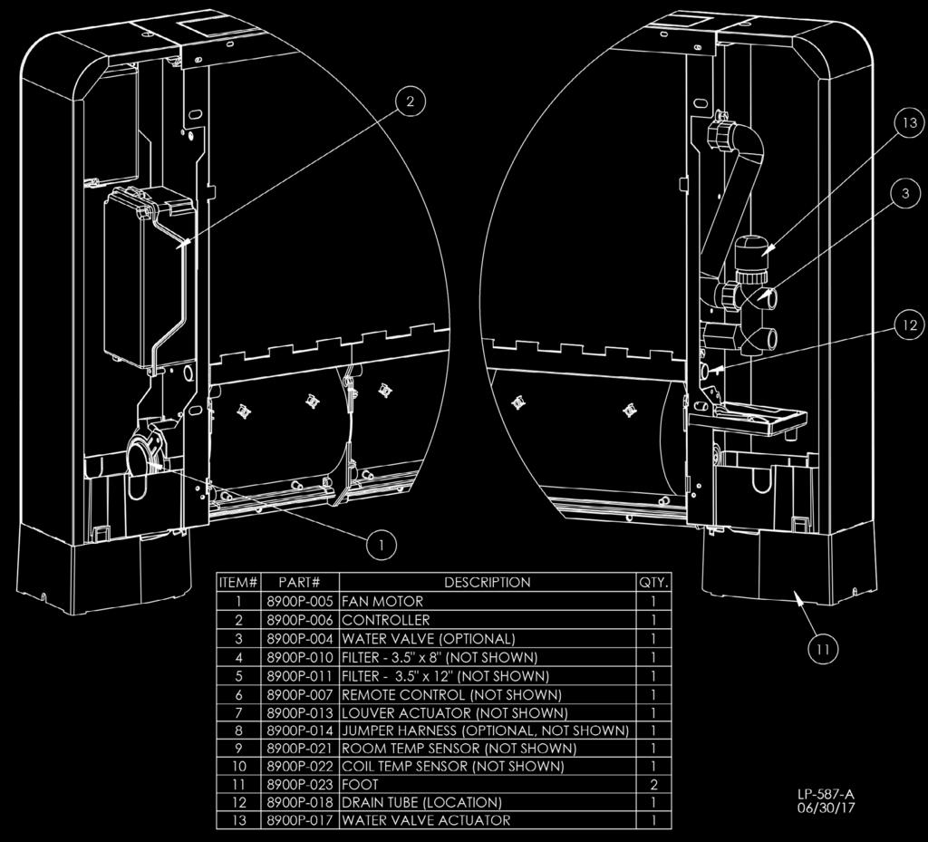
21 21 Figure 43 - Replacement Parts
22 22 Ultra Thin Hydronic Fan Coil Limited Five (5) Year Warranty For Residential and Commercial Use HTP warrants each ultra thin hydronic fan coil and its components to be free from defects in materials and workmanship according to the following terms, conditions, and time periods. UNLESS OTHERWISE NOTED THESE WARRANTIES COMMENCE ON THE DATE OF INSTALLATION. This limited warranty is only available to the original consumer purchaser (hereinafter Owner ) of the fan coil, and is non-transferable. COVERAGE A. During the first year after the original date of installation in the dwelling, HTP warrants that it will repair or replace, at its option, any defective or malfunctioning component of the hydronic fan coil that is found to have failed due to manufacturer s defect. Replacement components will be warranted for ninety (90) days. B. Should a defect or malfunction result in a leakage of water from the fan coil within the above-stated warranty periods due to defective material or workmanship, malfunction or failure to comply with the above warranty, with such defect or malfunctioning having been verified by an authorized HTP representative, HTP will replace the defective or malfunctioning fan coil with a replacement of the nearest comparable model available at the time of replacement. The replacement fan coil will be warranted for the unexpired portion of the applicable warranty period of the original fan coil. C. In the event of a leakage of water of a replacement fan coil due to defective material or workmanship, malfunction, or failure to comply with the above warranty, HTP reserves the right to refund to the Owner the published wholesale price available at the date of manufacture of the original fan coil. D. If, at the time of a request for service the Owner cannot provide a copy of the original sales receipt or the warranty card registration, the warranty period for the fan coil shall then be deemed to have commenced thirty (30) days after the date of manufacture of the fan coil and NOT the date of installation of the fan coil. E. If government regulations, industry certification, or similar standards require the replacement fan coil or component(s) to have features not found in the defective fan coil or component(s), the Owner will be charged the difference in price represented by those required features. If the Owner pays the price difference for those required features and/or to upgrade the size and/or other features available on a new replacement fan coil or component(s), the Owner will also receive a complete new limited warranty for that replacement fan coil or component(s). F. This warranty extends only to fan coils utilized in applications that have been properly installed by qualified professionals based upon the manufacturer s installation instructions. G. It is expressly agreed between HTP and the Owner that repair, replacement, or refund are the exclusive remedies of the Owner. H. HTP will not accept claims from the Owner for labor costs incurred by any person as a result of the repair, replacement, removal, or reinstallation of a fan coil or any component thereof. OWNER RESPONSIBILITIES The Owner or Installer must: 1. Maintain the fan coil in accordance with the maintenance procedure listed in the manufacturer s provided instructions. Preventive maintenance can help avoid any unnecessary breakdown of the fan coil. 2. Maintain all related system components in good operating condition. 3. Keep the fan coil free of damaging scale deposits. 4. Make provisions so if the fan coil or any component or connection thereto should leak, the resulting flow of water will not cause damage to the area in which it is installed. WARRANTY EXCLUSIONS This limited warranty will not cover: 1. Any fan coil purchased from an unauthorized dealer. 2. Any fan coil not installed by a qualified heating installer/service technician, or installations that do not conform to any applicable national or local building codes. 3. Service trips to teach the Owner how to install, use, maintain, or to bring the fan coil installation into compliance with local building codes and regulations. 4. Failure to locate the fan coil in an area where leakage of the fan coil or water line connections will not result in damage to the area adjacent to the fan coil or lower floors of the structure. 5. Any failed components of the system not manufactured by HTP as part of the fan coil. 6. Fan coils repaired or altered without the prior written approval of HTP. 7. Damages, malfunctions, or failures resulting from improper installation, or failure to install the fan coil in accordance with applicable building codes/ordinances or good plumbing and electrical trade practices; or failure to operate and maintain the fan coil in accordance with the manufacturer s provided instructions. 8. Damages, malfunctions, or failures resulting from failure to operate the fan coil at pressures not exceeding the working pressure shown on the rating label. 9. Failure or performance problems caused by improper sizing of the fan coil or piping, electric service voltage, wiring or fusing. 10. Damages, malfunctions, or failures caused by operating the fan coil with modified, altered, or unapproved components, or any component / attachment not supplied by HTP. 11. Damages, malfunctions, or failures caused by abuse, accident, fire, flood, freeze, lightning, acts of God and the like. 12. Failure of the fan coil due to the accumulation of solid materials or lime deposits. 13. Any damage or failure resulting from improper water chemistry. WATER CHEMISTRY REQUIREMENTS Sodium less than 20mGL. Water ph between 6.0 and 8.0. Hardness less than 7 grains. Chlorine concentration less than 100 ppm. 14. Fan coils replaced for cosmetic reasons due to damages to the exterior (scratches, dents, etc.) 15. Components of the fan coil that are not defective, but must be replaced during the warranty period as a result of reasonable wear and tear. 16. Components of the fan coil that are subject to warranties, if any, given by their manufacturers. HTP does not adopt these warranties. 17. Fan coils installed outside the fifty states (and the District of Columbia) of the United States of America and Canada. 18. Fan coils moved from the original installation location. 19. Fan coils that have had their rating labels removed. 20. Any labor charges incurred by any person in connection with the examination or replacement of a fan coil or parts claimed by the Owner to be defective. PROCEDURES FOR WARRANTY SERVICE REQUESTS Any claim for warranty assistance must be made immediately upon finding the issue. First, please consult the HTP Warranty Wizard ( to check warranty eligibility. You may also contact HTP Technical Support at for questions or assistance. Warranty coverage requires review and approval of the issue with HTP Technical Support or through the Warranty Wizard prior to a full unit replacement. Any claim for warranty reimbursement will be rejected if prior approval from HTP is not obtained in advance of a full unit replacement. Final determination will be made as part of the warranty claim process. When submitting a warranty claim the following items are required:
23 23 1. Proof of purchase or installation of the product Typically a copy of the invoice from the installing contractor, the receipt of the purchase of the product, or an original certificate of occupancy for a new home. 2. Clear pictures (or video) of the following: a. Serial number tag (sticker) b. The product c. The product issue / failure whenever possible d. A picture of the piping near the product e. For gas fired products, a picture of the venting, including how it exits the building All claims will be reviewed by HTP within three (3) business days. If additional information is required and requested by the HTP Claims Department you will have thirty (30) days to provide it. When all requested information is provided HTP will respond within three (3) business days. The claim will be automatically closed if requested information is not provided within thirty (30) days. Claims will not be reopened without HTP Warranty Supervisor approval. During the claims process a product that must be replaced will be given a designation of either a) field scrap, or b) return to HTP. If the product must be returned to HTP, the returned product must arrive at HTP within thirty (30) days of the date of our request to return the product. After receipt of the returned product HTP may require as many as thirty (30) additional days for product testing. NOTE: Any components or heaters returned to HTP for warranty analysis will become the property of HTP and will not be returned, even if credit is denied. If you have questions about the coverage of this warranty, please contact HTP at the following address or phone number: HTP, 272 Duchaine Blvd., New Bedford, MA, 02745, Attention: Warranty Service Department, 1(800) NO OTHER EXPRESS WARRANTIES This warranty gives the Owner specific legal rights. The Owner may also have other rights that vary from state to state. Some states do not allow the exclusion or limitation of incidental or consequential damages so this limitation or exclusion may not apply to the Owner. These are the only written warranties applicable to the fan coil manufactured and sold by HTP. HTP neither assumes nor authorizes anyone to assume for it any other obligation or liability in connection with said fan coils. HTP reserves the right to change specifications or discontinue models without notice. SERVICE, LABOR AND SHIPPING COSTS This limited warranty does not extend to any shipping charges, delivery expenses, or administrative fees incurred by the Owner in repairing or replacing the fan coil or component(s). This warranty does not extend to any labor costs incurred by any person as a result of the repair, replacement, removal, or reinstallation of a fan coil or any component thereof. All such expenses are the Owner s responsibility. LIMITATIONS OF THIS HTP WARRANTY AND REMEDIES THE FOREGOING WARRANTIES ARE EXCLUSIVE AND ARE GIVEN AND ACCEPTED TO THE FURTHEST EXTENT UNDER APPLICABLE LAW IN LIEU OF ANY AND ALL OTHER WARRANTIES, EXPRESS OR IMPLIED, INCLUDING WITHOUT LIMITATION THE IMPLIED WARRANTIES OF MERCHANTABILITY AND FITNESS FOR A PARTICULAR PURPOSE AND ANY OBLIGATION, LIABILITY, RIGHT, CLAIM OR REMEDY IN CONTRACT OR TORT, WHETHER OR NOT ARISING FROM HTP S NEGLIGENCE, ACTUAL OR IMPUTED. THE REMEDIES OF THE OWNER SHALL BE LIMITED TO THOSE PROVIDED HEREIN TO THE EXCLUSION OF ANY OTHER REMEDIES INCLUDING WITHOUT LIMITATION, INCIDENTAL OR CONSEQUENTIAL DAMAGES, SAID INCIDENTAL AND CONSEQUENTIAL DAMAGES INCLUDING, BUT NOT LIMITED TO, PROPERTY DAMAGE, LOST PROFIT OR DAMAGES ALLEGED TO HAVE BEEN CAUSED BY ANY FAILURE OF HTP TO MEET ANY OBLIGATION UNDER THIS AGREEMENT INCLUDING THE OBLIGATION TO REPAIR AND REPLACE SET FORTH ABOVE. NO AGREEMENT VARYING OR EXTENDING THE FOREGOING WARRANTIES, REMEDIES OR THIS LIMITATION WILL BE BINDING UPON HTP. UNLESS IN WRITING AND SIGNED BY A DULY AUTHORIZED OFFICER OF HTP. THE WARRANTIES STATED HEREIN ARE NOT TRANSFERABLE AND SHALL BE FOR THE BENEFIT OF THE OWNER ONLY.

24 24 Customer Installation Record Form The following form should be completed by the installer for you to keep as a record of the installation in case of a warranty claim. After reading the important notes at the bottom of the page, please also sign this document. Customer s Name Date of Installation Installation Address Product Name / Serial Number(s) Comments Installer s Code / Name Installers Phone Number Signed by Installer Signed by Customer IMPORTANT Customer: Please only sign after the installer has fully reviewed the installation, safety, proper operation, and maintenance of the system. If the system has any problems please call the installer. If you are unable to make contact, please call your sales representative. Distributor / Dealer: Please insert contact details. Correct Disposal of this Product This marking indicates that this product should not be disposed with other household wastes. Recycle it responsibly to promote the sustainable reuse of material resources and prevent possible harm to the environment or human health from uncontrolled waste disposal.
Superstor Pro Pool Heaters
 Superstor Pro Pool Heaters Installation Start-Up Maintenance Parts Warranty SSP-20PH Model CAUTION The use of a salt chlorine generator is prohibited in a system serviced by this pool heater. Salinated
NOTE TO CONSUMER: PLEASE KEEP ALL INSTRUCTIONS FOR FUTURE REFERENCE.
 Superstor Glass Lined Storage Tanks Installation Start-Up Maintenance Parts Warranty For Residential and Commercial Use GL Models* *Available in Metal Jacketed ASME and Non-ASME Models The surfaces of
Quick Zone Manifold. Installation. Start-Up. Maintenance. Parts. Warranty. For Residential and Commercial Use
 Quick Zone Manifold Installation Start-Up Maintenance Parts Warranty For Residential and Commercial Use QZM*140-1 / QZM*220-1 QZM*140-2 / QZM*220-2 QZM*140-3 / QZM*220-3 QZM*140-4 / QZM*220-4 Models *
Chiltrix 5.1 Thin DC - Inverter Water Fan Coil Unit Floor, Wall or Ceiling Universal Mount Manual
 Chiltrix 5.1 Thin DC - Inverter Water Fan Coil Unit Floor, Wall or Ceiling Universal Mount Manual Version 1.5 1 CONTENTS CHAPTER 1 GENERAL INTRODUCTION...3 1. Preface... 3 2. Product Introduction... 3
SuperStor Ultra Stainless Steel Storage Tank
 SuperStor Ultra Stainless Steel Storage Tank INSTALLATION START-UP MAINTENANCE PARTS Storage Tank Models SSU-30CB / SSU-45CB SSU-60CB / SSU-80CB / SSU-119CB For Residential and Commercial Use This manual
SuperStor Contender Indirect Fired Water Heater
 SuperStor Contender Indirect Fired Water Heater INSTALLATION START-UP MAINTENANCE PARTS SuperStor Contender Water Heater Models SSC-35 / SSC-50 / SSC-80 / SSC-119* *NOTE: A suffix of S denotes Solar Model
Indirect Water Heaters
 Indirect Water Heaters Installation Start-Up Maintenance Parts Warranty For Residential and Commercial Use WI Models This manual must only be used by a qualified installer / service technician. Read all
SuperStor Glass Lined Storage Tank
 SuperStor Glass Lined Storage Tank INSTALLATION MAINTENANCE TROUBLESHOOTING PARTS Storage Tank Models GL-50 / GL-80* GL-119* / GL-175* For Residential and Commercial Use *Available in Metal Jacketed ASME
Superstor Ultra NOTE TO CONSUMER: PLEASE KEEP ALL INSTRUCTIONS FOR FUTURE REFERENCE.
 Superstor Ultra Indirect Fired Installation Water Heaters Start-Up Maintenance Parts Warranty For Residential and Commercial Use SSU Models The surfaces of these products contacted by potable (consumable)
Thermostat Series. Installation Manual TSTBM-RRS--TW-A Revised 02-13
 Installation Manual Thermostat Series TSTBM-RRS--TW-A Remote Temperature Sensor (Requires TSTBM3H2CPH6W-A) TSTBM-RRS--TW-A 2 TSTBM-RRS--TW-A Table Of Contents Table of Contents Thermostat Quick Reference...
5) Do not start or stop the unit by inserting or pulling out the power plug.
 Do not start or stop the unit by inserting or pulling out the power plug.") 3058080 V170306 PURCHASE INFORMATION Thank you for choosing a Soleus Air Portable Air Conditioner. This Owner s Manual will provide you with valuable information necessary for the proper care and maintenance
3058080 V170306 PURCHASE INFORMATION Thank you for choosing a Soleus Air Portable Air Conditioner. This Owner s Manual will provide you with valuable information necessary for the proper care and maintenance
Residential Electric Water Heaters
 Residential Electric Water Heaters Use and Care Manual Installation Start-Up Maintenance Parts Warranty This manual must only be used by a qualified installer / service technician. Read all instructions
CWR265SZ 26 Bottle Built-in Wine Cooler Owner s Manual
 CWR265SZ 26 Bottle Built-in Wine Cooler Owner s Manual This owner s manual provides instructions on safe installation use, and troubleshooting assistance. Please read it carefully and save it for reference
MaxLite LED Vapor Tight Linear Fixture
 General Safety Information To reduce the risk of death, personal injury or property damage from fire, electric shock, falling parts, cuts/abrasions, and other hazards read all warnings and instructions
Portable Air Conditioner 6,000 BTU 8,000 BTU 10,000 BTU
 Portable Air Conditioner 6,000 BTU 8,000 BTU 10,000 BTU OPERATING INSTRUCTIONS PCR-06-01 PCR-08-01 PCR-10-01 3058080 V170223 PURCHASE INFORMATION Thank you for choosing a Chigo Portable Air Conditioner.
Light Duty Commercial Electric Water Heaters
 Light Duty Commercial Electric Water Heaters Use and Care Manual Installation Start-Up Maintenance Parts Warranty This manual must only be used by a qualified installer / service technician. Read all instructions
NOTE TO CONSUMER: PLEASE KEEP ALL INSTRUCTIONS FOR FUTURE REFERENCE.
 Drain Back Tank Installation Start-Up Maintenance Parts Warranty For Residential and Commercial Use DB Series and DBX Models* *A suffix of X denotes models with internal heat exchanger This manual must
NOTE TO CONSUMER: PLEASE KEEP ALL INSTRUCTIONS FOR FUTURE REFERENCE.
 Everlast Residential Electric Water Heaters Use and Care Manual Installation Start-Up Maintenance Parts Warranty This manual must only be used by a qualified installer / service technician. Read all instructions
Model No.: PS08-01 PS10-01 Ref: KY80 KY100
 8,000/10,000/12,000 BTU Portable Air Conditioner Operating Instructions Model No.: PS08-01 PS10-01 Ref: KY80 KY100 Model No.: PS12-03 Ref: KY120 3119233 V160310 Thank you for choosing a Soleus Air Portable
WMWLB / WMWFM / WTWLB / WTWFM Series Hydronic Heating Unit
 January 2008 WMWLB / WMWFM / WTWLB / WTWFM Series Hydronic Heating Unit Installation Operation Maintenance The units are designed for permanent up flow, counter flow, or horizontal left or right airflow
Installation Instructions
 P700U -21NHP Base Non -Programmable Thermostats Installation Instructions Designed and Assembled in the USA. US patents: US20060165149 A1, USD578026 SI, US6205041 B1 A14005 Base Non---Programmable Thermostat
Model RGAC/SGAC Self Contained Cooling/Gas Heat MODELS RGAC & SGAC - R22 USER'S INFORMATION, MAINTENANCE AND SERVICE MANUAL
 Model RGAC/SGAC Self Contained Cooling/Gas Heat Supersedes: 145.24-O1 (708) Units Form 145.24-O1 (908) MODELS RGAC & SGAC - R22 USER'S INFORMATION, MAINTENANCE AND SERVICE MANUAL CATEGORY III GAS HEATING/ELECTRIC
Everlast Electric. Water Heaters. Use and Care Manual. Installation. Start-Up. Maintenance. Parts. Warranty. Residential EVR Models
 Use and Care Manual Installation Start-Up Maintenance Parts Warranty Everlast Electric Water Heaters Residential EVR Models This manual must only be used by a qualified installer / service technician.
DUST FREE CARBON Whole House Air Purifier
 DUST FREE CARBON Whole House Air Purifier Installation & Operation Manual This manual covers the following model: DF CARBON 14" - #13052 GENERAL This device is designed to be installed into an existing
Hybrid Electric Residential Heat Pump Water Heaters
 Use and Care Manual Installation Hybrid Electric Residential Heat Pump Water Heaters Start-Up Maintenance Parts Warranty This manual must only be used by a qualified installer / service technician. Read
OPERATING INSTRUCTIONS
 OPERATING INSTRUCTIONS SPECIALTY REFRIGERATED TRANSPORT CABINETS FOR SATELLITE LOCATIONS RBQ-96 Caution: Read the instructions before using the machine. CONGRATULATIONS......and thank you for purchasing
INSTALLATION INSTRUCTIONS
 INSTALLATION INSTRUCTIONS Keep these instructions with the boiler at all times. BOYERTOWN FURNACE CO. PO Box 100 BOYERTOWN, PA 19512 1-610-369-1450 www.boyertownfurnace.com 5-25-12 2 Danger Warning Caution
FLCH4R Garage and Utility Electric Heater
 FLCH4R Garage and Utility Electric Heater Installation, Operation & Maintenance Instructions Model No. Volts Amps Watts BTU/HR Phase High Low High Low High Low Min Fuse Size* FLCH4R 208 17.3 8.66 3600
IAQ Series. Bosch IAQ Photo Catalytic Oxidizer (PCO) Residential Application. Installation Manual and Owner s Guide
 Residential Application. Installation Manual and Owner s Guide") Installation Manual and Owner s Guide IAQ Series Bosch IAQ Photo Catalytic Oxidizer (PCO) Residential Application PCOB-09012-0--A - 9" PCO BULB PCOB-14024-0--A - 14" PCO BULB 67202220344 Revised 07-12
Installation Manual and Owner s Guide IAQ Series Bosch IAQ Photo Catalytic Oxidizer (PCO) Residential Application PCOB-09012-0--A - 9" PCO BULB PCOB-14024-0--A - 14" PCO BULB 67202220344 Revised 07-12
Portable Air Conditioner with Heat Pump Technology PH4-10R-01, PH4-12R-01, & PH4-14R-01 Operating Instructions
 Portable Air Conditioner with Heat Pump Technology PH4-10R-01, PH4-12R-01, & PH4-14R-01 Operating Instructions 3092402 2006 Soleus Air International Thank you for choosing a Soleus Air Portable Air Conditioner
Blue Air. Commercial Refrigeration Inc. Installation & Operation Manual Ice Cream Freezers
 Blue Air Commercial Refrigeration Inc. Installation & Operation Manual Ice Cream Freezers Please read this manual completely before installing or operating this unit! BACF11 BACF15 BACRF14 Blue Air reserves
Installation & Operation Manual Ice Cream Freezers
 Installation & Operation Manual Ice Cream Freezers Please read this manual completely before installing or operating this unit! BACF11 BACF15 Blue Air reserves the right to make product modification at
INSTALLATION INSTRUCTIONS
 INSTALLATION INSTRUCTIONS FOR AQUECOIL HYDRONIC HEATING UNITS GENERAL INFORMATION The AQUECOIL Hydronic Heating Unit is offered in many different capacities and physical configurations in order to match
Use and Care Manual. Flammable Material Storage Refrigerator LRBFS06W1HC
 Use and Care Manual Flammable Material Storage Refrigerator LRBFS06W1HC 7085 471-00 Table of Contents Table of Contents Page Please Read and Follow these Instructions... 2 California Proposition 65...
Portable Air Conditioner, Dehumidifier,Heater and Fan utilizing Heat Pump Technology
 Portable Air Conditioner, Dehumidifier,Heater and Fan utilizing Heat Pump Technology OWNER'S MANUAL Model # KY-34 3046364 Please read owner s manual carefully before operating unit. TABLE OF CONTENTS INTRODUCTION...3
DEHUMIDIFIER. User Manual 50BT, 70BT
 User Manual DEHUMIDIFIER Model 50BT, 70BT Use & Care Guide Please read and follow all safety rules and instructions in this manual before operating. The product warranty is printed on the back of this
WMHP Series R410a Heat Pump INSTALLATION INSTRUCTIONS
 WMHP Series R410a Heat Pump INSTALLATION INSTRUCTIONS **WARNING TO INSTALLER, SERVICE PERSONNEL AND OWNER** Altering the product or replacing parts with non authorized factory parts voids all warranty
Installation Manual NPE-180A/240A WARNING. Add-on Controller Installation Kit
 Installation Manual Add-on Controller Installation Kit NPE-180A/240A This device is designed to work with NPE-180A/240A models ONLY. WARNING All Installations should be done only by a qualified expert
User s Manual and Warranty Information for Counterweighted Chain Drive ThyssenKrupp Access
 II User s Manual and Warranty Information for Counterweighted Chain Drive ThyssenKrupp Access Part #2139703 Rev. G II Table of Contents Introduction...3 Elevator Overview...4 Description of Features...5-7
Portable Air Conditioner and Heater With Heat Pump Technology Operating Instructions. Model No.: PH3-12R-03 Reference No.: KY2-34
 Portable Air Conditioner and Heater With Heat Pump Technology Operating Instructions 3046364 Model No.: PH3-12R-03 Reference No.: KY2-34 Thank you for choosing a Soleus Air Portable Air Conditioner. This
1500 Watt OIL FILLER RADIATOR INSTRUCTION MANUAL. pure indoor living MODEL BOF2001-CN
 pure indoor living 1500 Watt OIL FILLER RADIATOR MODEL BOF2001-CN INSTRUCTION MANUAL If after having read this leaflet, you have any questions or comments on your heater, call 1-800-253-2764 in North America.
Operating Instructions
 PH5-13R-35D Portable Air Conditioner with Heat Pump Operating Instructions 3092402 Item Number: LX-130 Model Number: PH5-13R-35D 201 Soleus Air International Thank you for choosing a Soleus Air PH5 Series
Portable Air Conditioner with Heat Pump Technology Operating Instructions. Model No.: HCB-P13HP-D. Reference No.: BPD13HP V140217
 Portable Air Conditioner with Heat Pump Technology Operating Instructions 3092402 Model No.: HCB-P13HP-D Reference No.: BPD13HP V140217 Thank you for choosing a Soleus Air Portable Air Conditioner with
Because you re not like everyone else. EVAPORATIVE COOLER EC220W OWNER S MANUAL
 Because you re not like everyone else. EVAPORATIVE COOLER EC220W OWNER S MANUAL 2 BECAUSE YOU RE NOT LIKE EVERYONE ELSE. And neither are we. Always at the forefront of our industry, our goal is to offer
Instruction Leaflet. Heater with Adjustable Thermostat PLEASE READ AND SAVE THESE IMPORTANT INSTRUCTIONS
 TRUSTED FOR OVER 100 YEARS Heater with Adjustable Thermostat * Fan-Forced Heaters may appear with a different grill design NOTE: A Phillips screwdriver is required for assembly. Instruction Leaflet PLEASE
20 High velocity Air
 20 High velocity Air Circulator 66878 Set up and Operating Instructions Distributed exclusively by Harbor Freight Tools. 3491 Mission Oaks Blvd., Camarillo, CA 93011 Visit our website at: http://www.harborfreight.com
Installation, Operation & Service Manual
 Installation, Operation & Service Manual WARNING Improper installation, adjustment, alteration, service or maintenance can result in death, injury or property damage. Read the Installation, Operation and
YOUR PORTABLE AIR PURIFIER
 YOUR PORTABLE AIR PURIFIER This booklet contains important information. CAUTION: Read manual carefully for proper procedures and operation. Thank you for purchasing your new Portable Air Purifier from
12,000 BTU Evaporative Portable Air Conditioner
 12,000 BTU Evaporative Portable Air Conditioner Owner s Manual Model # KY-32E Please read owner s manual carefully before operating the unit. TABLE OF CONTENTS PAGE Table of Contents. 2 Introduction....3
MIGHTY PRO 1/4 HP CHILLER
 1 MIGHTY PRO 1/4 HP CHILLER FOR TANKS UP TO 170 GALLONS TOP QUALITY & HIGHLY EFFICIENT INTEGRATED DUAL STAGE THERMOSTAT 2 ASSEMBLY PARTS FRONT TOP VIEW BACK 3 SET UP INSTRUCTIONS 1. Remove chiller and
Air Cleaning Equipment, Inc. 303 N. Main St. Broadway, NC iers.com
 Read and Save These Instructions Horizon Galaxy - Installation and Operations Manual Air Cleaning Equipment, Inc. 303 N. Main St. Broadway, NC 27505 www.horizondehumidif iers.com 1 Safety Notes: The Horizon
Sunleaves Air Conditioner
 Sunleaves Air Conditioner Thank you for purchasing this quality Sunleaves Air Conditioner! Please read through this manual completely, and keep it in case you need to reference the information in the future.
WatchDog NXT60. Installation and Operations Manual. Seaira Global, LLC NC Highway 50 Surf City, NC (910)
") WatchDog NXT60 Installation and Operations Manual Seaira Global, LLC 14021 NC Highway 50 Surf City, NC 28445 (910) 660-0962 Table of Contents Important Notes 2 Warranty Registration 2 Specifications 3
WatchDog NXT60 Installation and Operations Manual Seaira Global, LLC 14021 NC Highway 50 Surf City, NC 28445 (910) 660-0962 Table of Contents Important Notes 2 Warranty Registration 2 Specifications 3
Micro-Computer Induction Cooktop SR-1885SS
 Micro-Computer Induction Cooktop SR-1885SS INSTRUCTION MANUAL Thank you for your purchase. Please read thoroughly before initial use and keep in a safe place for future reference. INDEX Important safeguards....
WHAT TO DO IF YOU SMELL GAS
 AHE AHE SERIES 4 Direct Vent Wall-Mounted Boilers User s Information Manual If the information in this manual is not followed exactly, a fire or explosion may result, causing property damage, personal
Model No. PE2-07R / PE2-09R / 9000 BTU Portable Air Conditioner with dehumidifier & Fan PE2-07R-62 / PE2-09R-32 Operating Instructions
 7000 / 9000 BTU Portable Air Conditioner with dehumidifier & Fan PE2-07R-62 / PE2-09R-32 Operating Instructions 3046364 Model No. PE2-07R / PE2-09R 2006 Soleus Air International Thank you for choosing
Instruction Leaflet 99.97% TRUE HEPA AIR PURIFIER. pure indoor living MODEL: BAP925-CN. Replacement filters: A1230H and A1260C
 pure indoor living 99.97% TRUE HEPA AIR PURIFIER MODEL: BAP925-CN Instruction Leaflet Read instructions before operating. Retain for future reference. Questions? Comments? Call 1-800-253-2764 in North
SPA BLOWER OWNER'S MANUAL XXXX, XXXX, XXXX, XXXX, XXXX, XXXX fax
 SPA BLOWER OWNER'S MANUAL 80015-XXXX, 80016-XXXX, 80017-XXXX, 80018-XXXX, 80019-XXXX, 80020-XXXX fax 888.610.3839 2015 323300-015 6/15 THIS PAGE INTENTIONALLY LEFT BLANK. 2 Operating Instructions and Parts
Horizontal Bottle Cooler Installation and Operation Manual
 Speeds Up the Pace of Innovation Horizontal Bottle Cooler Installation and Operation Manual Please read this manual completely before attempting to install or operate this equipment! TBC-50SD, 50SB/ TBC-95SD,
Upright Freezer Congélateur vertical Congelador vertical
 Installation and User Manual Manuel d installation et d utilisation Manual de instalación y del usuario HFU0100ACW Upright Freezer Congélateur vertical Congelador vertical Part # 0570000002 TABLE OF CONTENTS
CABINET INFRARED HEATER
 **WARNING: READ THIS INSTRUCTION MANUAL CAREFULLY BEFORE USE. www.dellaproductsusa.com 909. 344. 2588 CABINET INFRARED HEATER INSTRUCTION MANUAL Item No: 050-HA-50082 Thank you for choosing a DELLA Infrared
ELECTRIC FIREPLACE OWNER S MANUAL
 ELECTRIC FIREPLACE OWNER S MANUAL MODELS EL1346C 4001358 WARNING: If the information in this manual is not followed exactly, a fire or electrical shock may result causing property damage, personal injury
12,000 BTU Portable Air Conditioner PE3-12R-03. Model No. PE3-12R Soleus Air International
 12,000 BTU Portable Air Conditioner Operating PE3-12R-03 Instructions 3092402 Model No. PE3-12R-03 2010 Soleus Air International Thank you for choosing a Soleus Air PE3-12R-03 Portable Air Conditioner.
Model No. GB-PAC-08E4. 8,000 BTU Portable Air Conditioner Operating Instructions
 Model No. GB-PAC-08E4 8,000 BTU Portable Air Conditioner Operating Instructions Thank you for choosing a Soleus Air Powered by Gree Portable Air Conditioner. This owner s manual will provide you with valuable
Aqua Balance. User s Information Manual. WMB-155C Wall Mount Gas-Fired Combination Boiler Heating and Domestic Hot Water
 Aqua Balance WMB-155C Wall Mount Gas-Fired Combination Boiler Heating and Domestic Hot Water User s Information Manual * Low Lead Content If the information in this manual is not followed exactly, a fire
SuperStor Ultra Indirect Fired Water Heaters
 SuperStor Ultra Indirect Fired Water Heaters INSTALLATION START-UP MAINTENANCE PARTS For Residential and Commercial Use This manual must only be used by a qualified installer/service technician. Read all
WKS 4000 SERIES (USA only) --INSTALLATION INSTRUCTIONS--
 --INSTALLATION INSTRUCTIONS--") 8610 Production Avenue San Diego, California 92121 (858) 566-7465 Fax (858) 566-1943 WKS 4000 SERIES (USA only) --INSTALLATION INSTRUCTIONS-- Thank you for choosing a BREEZAIRE cooling unit. We believe
8610 Production Avenue San Diego, California 92121 (858) 566-7465 Fax (858) 566-1943 WKS 4000 SERIES (USA only) --INSTALLATION INSTRUCTIONS-- Thank you for choosing a BREEZAIRE cooling unit. We believe
13500 BTU RV Air Conditioner Installation and Operating Instructions
 13500 BTU RV Air Conditioner Installation and Operating Instructions Model No.:HCB-R135-A-ID HCB-R135-A-OD 3092402 V140804 Thank you for choosing a Soleus Air RV Air Conditioner. This owner s manual will
Because you re not like everyone else. PORTABLE CLEAR ICE MAKER IM200SS OWNER S MANUAL. Manual v1.0
 Because you re not like everyone else. PORTABLE CLEAR ICE MAKER IM200SS OWNER S MANUAL Manual v1.0 2 BECAUSE YOU RE NOT LIKE EVERYONE ELSE And neither are we. Always at the forefront of our industry, our
CR13000-PAC OWNER S MANUAL. Portable Air Conditioner. PORTABLE AIR CONDITIONER with HEAT PUMP. Operating and Servicing Instructions
 OWNER S MANUAL Operating and Servicing Instructions CR13000-PAC PORTABLE AIR CONDITIONER with HEAT PUMP Portable Air Conditioner Questions or concerns? For assistance, please call Customer Service ClimateRight
1500W STOVE HEATER INSTRUCTION MANUAL. Item No: 050-HA-50090
 **WARNING: READ THIS INSTRUCTION MANUAL CAREFULLY BEFORE USE. www.dellaproductsusa.com 909. 344. 2588 1500W STOVE HEATER INSTRUCTION MANUAL Item No: 050-HA-50090 Thank you for choosing a DELLA Infrared
IMPORTANT SAFETY INFORMATION:
 Owner s Manual Model CUH05B31T IMPORTANT SAFETY INFORMATION: Always read this manual first before attempting to install or use this heater. For your safety, always comply with all warnings and safety instructions
Surna 25-Ton Chiller Operating & Maintenance Manual
 www.surna.com 303.993.5271 Surna 25-Ton Chiller Operating & Maintenance Manual Models: 300F3-3. 300F4-3, 300FW-3 Revised: July 2015 Table of Contents Warranty Information 4 Limited Warranty 4 Limitation
Installation Manual WARNING. Add-on Controller Installation Kit NPE-180A/210A/240A
 Installation Manual Add-on Controller Installation Kit NPE-180A/210A/240A This device is designed to work with NPE-180A/210A/240A water heaters ONLY. WARNING All Installations should be done only by a
Owner s Guide. 24-inch Gas Wall Oven with Time-Of-Day Clock and Timer Canada w A/01/08
 Owner s Guide 24-inch Gas Wall Oven with Time-Of-Day Clock and Timer TABLE OF CONTENTS IMPORTANT SAFETY INSTRUCTIONS... 2-4 MAINTENANCE... 11... Oven or broiler door... 11 CLOCK AND TIMER... 5 Oven bottom...
AIC Brazed Plate Heat Exchanger Operating and Instruction Manual
 AIC Brazed Plate Heat Exchanger Operating and Instruction Manual Advanced Industrial Components Page 1 of 8 Customer Service Call: 1-888-738-1350 1.0 Installation 1.1 Mounting/support unit: a) On a shelf
14,000 BTU Portable Air Conditioner 14,200 BTU Heat Pump Model Number: LX-140 Operating Instructions. Model No. LX Soleus Air International
 14,000 BTU Portable Air Conditioner 14,200 BTU Heat Pump Model Number: LX-140 Operating Instructions 3092402 Model No. LX-140 2012 Soleus Air International Thank you for choosing a Soleus Air LX-140 Portable
Outdoor Refrigerator USER S MANUAL
 Outdoor Refrigerator USER S MANUAL MODEL Number:BLZ-SSRF-40DH IMPORTANT:READ THIS USER S MANUAL PRIOR TO CONNECTING POWER AND USE Before the refrigerator is used, it must be PROPERLY POSITIONED, LEVELED
SEISCO SUPERCHARGER EXTENDER/BOOSTER INSTALLATION GUIDE & OWNERS MANUAL
 SEISCO SUPERCHARGER EXTENDER/BOOSTER INSTALLATION GUIDE & OWNERS MANUAL This manual is provided as a guide to installation. All installations must comply with any and all local and national electrical
America s Walk-In Tub. Installation & Instructions. Manufactured by. A Division of Spa World Corp NW 35th Avenue ANSI-Z124.1
 America s Walk-In Tub Installation & Operational Instructions REEF SOAKER ASME A112.19.7-2006 ANSI-Z124.1 Manufactured by ACCESS TUBS A Division of Spa World Corp. 5701 NW 35th Avenue Miami, Florida 33142
Wax Base Heater & Dispenser
 Wax Base Heater & Dispenser Service Manual Models: IDWB2/0900, IDWB2/0775, IDWB3/0900, IDWB3/0775, IDWB4/0900, IDWB4/0775 Introduction............................................................................
ECCOTEMP. Point of Use Tankless Water Heaters EP-2.4 / EP-7.0. Installation and Operating Instruction Manual. Shop Online.
 ECCOTEMP Point of Use Tankless Water Heaters EP-2.4 / EP-7.0 Installation and Operating Instruction Manual Product Support Eccotemp.com/help-desk Shop Online Eccotemp.com/products Store Locator Eccotemp.com/locator
Elite. User s Information Manual. Elite and Elite VWH* All Models
 Elite User s Information Manual Elite and Elite VWH* All Models Heat Exchanger Bears the ASME H Stamp IF THE INFORMATION IN THIS MANUAL IS NOT FOLLOWED EXACTLY, A FIRE OR EXPLOSION MAY RESULT, CAUSING
Honeywell Garrett Drop-in Intercooler for 2.3L Mustang EcoBoost IMPORTANT INFORMATION - PLEASE READ CAREFULLY
 Honeywell Garrett Drop-in Intercooler for 2.3L Mustang EcoBoost Bill of Materials and Precautions Application: 2015+ Ford Mustang 2.3L EcoBoost Part Number: 857564-6001 Part List: Item Description QTY
OPERATION, SERVICE & PARTS MANUAL
 OPERATION, SERVICE & PARTS MANUAL BROASTER 620NXP & 621 EASY BREADER Be sure ALL installers read, understand, and have access to this manual at all times. MODEL 620NXP MODEL 621 Genuine Broaster Chicken,
IMPORTANT SAFETY INSTRUCTIONS EC-AG1-25 EC-AG1, EC-AG2 SAVE THESE INSTRUCTIONS.
 IMPORTANT SAFETY INSTRUCTIONS 2 1. Read and Follow All Instructions 2. Read this manual completely before attempting installation. 3. All permanent electrical connections should be made by a qualified
Installation and Maintenance "L" and "LS" Series
 Installation and Maintenance "L" and "LS" Series IB-43-E This bulletin should be used by experienced personnel as a guide to the installation and maintenance of "L" and "LS" Series ultra capacity float
Professional Warming Drawer and Warming Drawer Cabinet
 Professional Warming Drawer and Warming Drawer Cabinet Care & Use/Installation Instructions Models: (C)VQEWD5300SS (C)VQEWD5420SS IMPORTANT SAFETY INSTRUCTIONS WARNING: Read this manual carefully and completely
ELECTRIC FIREPLACE INSTRUCTION MANUAL. Item No: 050-HA Model No. FP405R-QA
 **WARNING: READ THIS INSTRUCTION MANUAL CAREFULLY BEFORE USE. www.dellaproductsusa.com 909. 344. 2588 ELECTRIC FIREPLACE Model No. FP405R-QA INSTRUCTION MANUAL Item No: 050-HA-50099 2 Thank you for choosing
BEFORE USE, PLEASE READ AND FOLLOW ALL SAFETY RULES AND OPERATING INSTRUCTIONS
 WINE CELLAR Model SWC1840 Owner s Manual BEFORE USE, PLEASE READ AND FOLLOW ALL SAFETY RULES AND OPERATING INSTRUCTIONS Write the Serial Number here Felix Storch, Inc. Summit Appliance Division An ISO
Portable Air Conditioner with Evaporative Technology PE6-10R-03 Operating Instructions. Model No. PE6-10R Soleus Air International
 Portable Air Conditioner with Evaporative Technology PE6-10R-03 Operating Instructions 3046364 Model No. PE6-10R-03 2011Soleus Air International Thank you for choosing a Soleus Air Portable Air Conditioner.
Thermometer model 02059
 Instruction Manual Thermometer model 02059 pm CONTENTS Unpacking Instructions... 2 Package Contents... 2 Product Registration... 2 Features & Benefits: Sensor... 2 Features & Benefits: Display... 3 Setup...
OPERATING AND INSTALLATION MANUAL
 OPERATING AND INSTALLATION MANUAL TANKLESS ELECTRIC WATER HEATER WITH ELECTRO-MECHANICAL FLOW SWITCH» MINI 2» MINI 2.5» MINI 3» MINI 3.5» MINI 4» MINI 6 The Mini series is tested and certified by WQA against
11,000 BTU Portable Air Conditioner with dehumidifier & Fan PE4-11R-03 Operating Instructions. Model No. PE4-11R Soleus Air International
 11,000 BTU Portable Air Conditioner with dehumidifier & Fan PE4-11R-03 Operating Instructions Model No. PE4-11R-03 2006 Soleus Air International Thank you for choosing a Soleus Air Portable Air Conditioner.
Because you re not like everyone else. PORTABLE CLEAR ICE MAKER IM200SS OWNER S MANUAL
 Because you re not like everyone else. PORTABLE CLEAR ICE MAKER IM200SS OWNER S MANUAL 2 BECAUSE YOU RE NOT LIKE EVERYONE ELSE. And neither are we. Always at the forefront of our industry, our goal is
Turbo Air Speed up the Pace of Innovation TBB-4SB CAUTION! PLEASE KEEP POWER SWITCH ON BEFORE OPERATING THIS EQUIPMENT
 Turbo Air Speed up the Pace of Innovation CAUTION! PLEASE KEEP POWER SWITCH ON BEFORE OPERATING THIS EQUIPMENT Underbar Equipment Back Bars Installation and Operation Manual Please read this manual completely
PORTABLE AIR CONDITIONER OWNER S MANUAL
 PORTABLE AIR CONDITIONER OWNER S MANUAL ASSEMBLY AND OPERATING INSTRUCTIONS MODELS: JHS-A018-10KR SKU#: 130004 JHS-A018-12KRH SKU#: 130005 JHS-A018-14KRH SKU#: 130009 WARNING: Read and follow all warnings
INSTALLATION AND OPERATION MANUAL STEAM COIL BASE CONVECTION STEAMER MODEL SCX-16
 INSTALLATION AND OPERATION MANUAL STEAM COIL BASE CONVECTION STEAMER MODEL SCX-16 CROWN FOOD SERVICE EQUIPMENT LTD. 70 OAKDALE ROAD, DOWNSVIEW, (TORONTO), ONTARIO, CANADA, M3N 1V9 TELEPHONE: (416) 746-2358,
Thermometer with Wired Sensor
 Instruction Manual Thermometer with Wired Sensor model 02042 CONTENTS Unpacking Instructions... 2 Package Contents... 2 Product Registration... 2 Features & Benefits... 3 Setup... 4 Temperature Units...
26 LB CAPACITY ICE MAKER
 26 LB CAPACITY ICE MAKER INSTRUCTION MANUAL CATALOG NUMBER BIMY126S Thank you for choosing BLACK+DECKER! PLEASE READ BEFORE RETURNING THIS PRODUCT FOR ANY REASON. If you have a question or experience a