TECHNICAL MANUAL FORCED CIRCULATION SYSTEMS
|
|
|
- Lucas Wilkerson
- 5 years ago
- Views:
Transcription

1 TECHNICAL MANUAL FORCED CIRCULATION SYSTEMS BOILERS SOLAR COLLECTORS HYDRAULIC KIT
2 INTRODUCTION A company that proposes sunny solutions, working with passion and devotion, for three decades now, to always offer the best. A philosophy that leads our steps, and makes us, as professionals, feel the weight of responsibility and obligation to offer products and services that are in harmony with the environment and man. So that we hand over a better world to our children. We live in times with great ecological problems. Planet Earth is sounding the alarm of ecological danger. The thoughtless use of mineral energy sources is resulting in increased pollution of the atmosphere, above tolerance levels. Ecosystems are either being transformed or destroyed. While mineral energy reserves are continuously decreasing and prices continuously rising, we look at the sun and consider that it radiates over times the energy needs of our planet. So why not direct ourselves to the inexhaustible, free, and above all clean solar energy?
3 CONTENTS Why should we use a solar system page 4 Packaging....page 5 Hot water consumption / use Calculation of needs / Examples... page 6 What a solar system consists of: (technical characteristics, specifications) Solar collectors....page 8 Boiler...page 15 Boiler NOVASUN type V-BL1, with one tube heat exchanger.... page 17 Boiler NOVASUN type V-BL2, with two tube heat exchangers... page 20 Differential Thermostat...page 23 Hydraulic kit...page 25 Peripheral accessories - Basic Accessories... page 27 Peripheral accessories - Optional Accessories... page 28 Models...page 29 Typical installation diagram...page 30 Function...page 31 Installation Instructions Support base of collectors...page 32 Connection of collectors and accessories... page 40 Hydraulic kit and pipes...page 42 Electric connections...page 45 Troubleshooting check-list Instructions to the customer and Installer... page 46 Troubleshooting check-list...page 46 Installation sheet...page 47 Instructions for the Installer...page 49
4 SOLAR SYSTEM Why should we use a Solar System A solar system Is Ecologically friendly. Economical, Simple, Aesthetic, Effective and Autonomous: Ecologically friendly: with a NOVASUN VS 500E system, the emissions of C0 2 avoided annually are equivalent to the fuel emissions of a car having run for km. Economical: will decrease your cost for energy by % because the burnerand electric resistance will not need to operate for at least 7-12 months of the year, depends on the sun radiation of each area and the size of the system. Simple: The well-studied selection of materials of NOVASUN make Its Installation safe and easy, reducing the time needed for Its Installation toa minimum. Aesthetic: The excellent exterior design of the NOVASUN collectors in combination with their well-studied support base, offer the possibility of a tangent Installation on tiled roofs matching aesthetically with every architectural building design. Effective and Autonomous: You have hot water at will 7-12 months per year. During winter time you secure the pre-heating of the water, and the extra hot water needed is secured from conventional energy. 4
 or with two tube heat exchangers (type VS-BL2) on a wooden palette and wrapped with stretch film. 2.")
 which are required for the installation of the system like hydraulic kit, expansion pot, differential thermostat with plastic case,")

5 PACKAGING The forced circulation system NOVASUN consists of Thank you for choosing to buy a solar system NOVASUN VS - BL1 or VS - BL2. Every system which you acquire consists of: 1. Boiler with one tube heat exchanger (type VS-BL1) or with two tube heat exchangers (type VS-BL2) on a wooden palette and wrapped with stretch film. 2. One (1), Two (2), or Three (3) collectors which are protected during their transport with 4 plastic elbows of hard plastic. 3. Cardboard box with all of the accessories (except pipes and wires) which are required for the installation of the system like hydraulic kit, expansion pot, differential thermostat with plastic case, antifreeze liquid and various connection accessories in individual plastic packaging. Externally the box refers to the model of the system for which the accessories are for. 4. Cardboard box with the metal plates of the support base, the screws, moly plugs, the bolts etc Kits can be delivered packaged on one palette upon a special request. The merchandise travels under buyers responsibility and risk. The specifications of the products and their accessories can change any time without prior notice. Settlement of any dispute are under the jurisdiction of the courts of Athens in Greece. HELIOAKMI S.A. reserves the right to change all specifications of the products and their accessories without prior notice. 5
6 HOT WATER CONSUMPTION General Information When choosing a solar system for hot water we must first determine our needs for hot water, in quantity as well as in preferred temperature of consumption. The typical calculation for the temperature for consumption is 45ºC, but for the calculation of required quantity you must take into account the daily needs. Calculation of needs for hot water usage 1) RESIDENCES In family residences, the needs for hot water remain stable during the whole year. An indication for the needs is given by the number of individuals living in the building (or apartment). Usually, the per capita daily consumption of hot water at 45ºC is calculated taking into consideration the following: Low consumption: 35 liters per capita / day Medium consumption: 60 liters per capita / day High consumption: 80 liters per capita / day In the case where we want to connect to the solar installation the washing machine and the dishwasher, we would have to increase the calculated daily needs of consumption as follows: Washing Machine: 20 liters / day (1 wash per day) Dishwasher: 20 liters / day (1 wash per day) Example: A family of 4 persons needs around 240 liters of hot water daily in order to have a medium daily consumption. (60 liters per capita x 4 persons). If we include a washine machine and dishwasher, then we must calculate a consumption of 280 liters per day. 2) HOTELS - HOSTELS General Information on needs of hot water In buildings such as hotels, hostels, etc, the needs for hot water are related to the amount of customers. In this case the daily consumption is calculated by the average occupancy of the rooms, from the period of May up until August. Using this basis, the size of the proposed installation is determined. Here below we indicate the per capita daily need for hot water at 45ºC Hostels with rooms with shared bath: 35 liters / person / day Hostels: 40 liters / person / day 2 Star Hotels: 50 liters / person / day 3 Star Hotels: 80 liters / person / day 4 Star Hotels: 100 liters / person / day Camping: 60 liters / person / day 6
7 HOT WATER CONSUMPTION Example: General Information on needs of hot water An installation of agrotourism is maintained by a family of 4 persons, that live in the residence. During the period between May and August the average occupancy is 15 clients per day. For the occupants 2 meals are prepared per day and the dishwasher washes 5 times per day. Needs of family: 4 x 60 lt = 240 litres / day Needs of the clients : 15 x 50 lt = 750 litres / day Kitchen: 30 x 10 lt = 300 litres / day Dishwasher: 5 x 20 lt = 100 litres / day Total: litres / day 3) OTHER APPLICATIONS In the next table we present the daily consumption for other applications: Hospitals and clinics : 80 litres / bed University residences: 80 litres / bed Dressing rooms, public showers: 20 litres / person Schools: 5 litres / student Restaurants : 8 to 15 litres / meal Bars: 2 litres / client Prisons: 30 litres / person Factories : 20 litres / persona Offices : 5 litres / employee Gymnasiums : 30 litres / user The information of the above table can also be used in combinations so that in every case the average daily consumption can be properly calculated. FACTORS OF INCREASED NEEDS In the case that a recirculation system exists for the hot water usage, you will also have to take this into account for the needs. The calculation will have to be made every time individually from the above tables and depends on the dimensions of the circuit and it s thermal insulation. Additionally, in the determination of the total needs, the thermal losses of the total distribution circuit from the point of storage to the points of final consumption must be taken into consideration. REAL NEEDS In every case, the real needs for hot water are related to the personal attitude, the possible special characteristics and habits of every place and application and also the way each application functions. For this reason, a specific calculation can be made by using the information on the gas/ petrol or eletric bill. A flow meter installed on the hot water pipes could also be used. 7

8 SOLAR COLLECTORS SOLAR COLLECTORS MODELS ST-2000 AND ST-2500 Collector with black paint coating Description Flat solar collector, firmly built, of new technology suitable for all forced circulation solar systems. The production process and the raw materials that are used produce a high thermal energy efficiency even during periods with insufficient radiation. Models The solar collectors NOVASUN are produced in two types, ST-2000 (2,10 m 2 ) and ST-2500 (2,61 m 2 ), with black paint coating or a blue titanium selective treatment, which either in solo or in combinations cover all of the requirements of solar systems. Basic Technical Characteristics Frame made from stainless aluminum, which is extremely durable to adverse climatic conditions (high humidity - coastal areas). Strong side and back insulation (20mm glass wool and 40mm rock wool), minimize thermal losses in areas with low seasonal temperatures. Special prismatic glass, resistant to hale (solar tempered glass). Absorber made from copper treated with a blue colour titanium selective coating or with black paint. The absorber with titanium coating is ideal for regions with high diffused radiation and low temperatures, absorbing up to 16% more solar radiation in winter months compared to simple black chrome absorbers. This method of coating is non toxic and does not pollute the environment, while keeping stable its mechanical and optical properties during high and low temperatures. DIMENSIONS OF THE SOLAR COLLECTORS TYPE Dimensions Gross Net Weight Capacity Test Max. working Absorber SELECTIVE (m 2 ) Surface Surface (kg) (L) Pressure Pressure a e (m 2 ) (m 2 ) (bar) (bar) ST x1010x90 2,10 1,8 43 1, ST x1275x90 2,61 2, , %±2% 5%±3% HELIOAKMI S.A. reserves the right to change all specifications of the products and their accessories without prior notice. 8
9 SOLAR COLLECTORS SOLAR COLLECTORS MODELS ST-2000 AND ST-2500 SELECTIVES Technical Characteristics: Absorber: a unique sheet of copper shett Thermal Absorption: 95% Thermal loss: 5% Thickness: 0,2mm Coating: selective titanium Characteristics of the tubes: Diameter of the horizontal tubes: ( 22mm) Diameter of the vertical tubes: ( 10mm ou 8mm) Material: copper Test Pressure: 10 bars Maximum functional pressure: 7 bars Frame: Material: heavy aluminum profile Back insulation: mm insulation Side insulation: 20 mm glasswool Cover: Material: solar tempered glass Thickness: 3,5mm or 4mm Watertightness: joint EPDM and transparent silicone General Characteristics: Total thermal efficiency: 95% ± 2% Total thermal losses: 5% ± 3% Antifreeze: glicol appropriate for solar systems Collector with titanium selective treatment Support base: The characteristics of the support base for the collector(s) with the ways of installation on the various types of roofs, are described analytically on page 32, Chapter 5, Installation Instructions. HELIOAKMI S.A. reserves the right to change all specifications of the products and their accessories without prior notice. 9
10 SOLAR COLLECTORS Efficiency curves of NOVASUN solar collectors ST 2000 Selective (2,10m 2, 24ºC) ST 2500 Selective SUN-POWER Selective a. Test Nr: 1021 b. Test Nr: c. Test Nr Curve a: Test by DEMOKRITOS (Grece) n= 0,85-5,44 T* Curve b: Test by CENER (Spain) n= 0,767-0,37 (tm - ta)/g Curve c: Test by TÜV Bayern (Germany) n=0, T*- 0,0157 (θm-θl)t* Curbe d: Calculs CSTBat (France) y = -4,8648x + 0,7063 d. Avis Technique 14/ Procedure for the calculation of estimated energy output of collector The collector instantaneous efficiency curve is expressed by the following relation in linear or second-order form: where n is the collector instantaneous efficiency, Tm is the mean temperature of water inside the collector, in ºC, Ta is the ambient air temperature, in ºC and G is the total solar radiation that falls in the collector, in W/m2. The parameters of the above equations of the instantaneous efficiency curve n0 and U0 are determined by testing according to the standards EN and ISO The estimated energy output of the collector is calculated using the values of parameters n0 and U0, as these have been determined by testing from several accredited laboratories of Europe, for a number of cities and under the following conditions: - solar radiation, ambient air temperature and temperature of cold water (average monthly values as given in the tables of the following page) - temperature of hot water delivered by the collector to the user equal to 45ºC and 40ºC. For every day of the month the efficiency of the collector is calculated, where the maximum efficiency and the heat losses of the collector are taken into account depending on the existing climatic conditions of the day and the desired temperature of hot water delivered by the collector to the user. Also, the latitude of the area of installation and the slope of the collector are taken into account. Following this, the mean monthly output of the collector is calculated using the climatic data of the month. Finally, the sum of the mean monthly outputs of the collector gives the total annual output. It is noted that the values of the estimated energy output of the collector that are calculated and given in the next tables are the maximum estimated and therefore they are achieved only by the optimum design and installation of the solar collector and the solar system. This means that that there must not be any shading of the collector during the hours of sunshine and operation of the system, any water penetration inside the collector from the rain, any accumulation of water in the inside part of the collector cover, any accumulation of dust or other substances on the outside part of the collector cover, any deformation of any part or area or material of the collector and system, any leakage in the hydraulic connections in any part of the collector or system, bad or no insulation of the piping of the solar system, bad operation of the valves of the solar system, non proper maintenance of the collector and the system and problems caused by deposition of salts within the tubes of the collector by the usage water. 10
11 SOLAR COLLECTORS CLIMATIC DATA OF SELECTED WORLD CITIES 11
12 SOLAR COLLECTORS Energy output of the collector in several cities of the world (in kwh/m 2 ) 12
13 SOLAR COLLECTORS GRAPHICAL REPRESENTATION OF ENERGY OUTPUT OF COLLECTORS IN SELECTED CITIES OF THE WORLD (in KWh/m2), in temperature 40ºC Collector: ST 2000 selective- Base of results: Test of DEMOKRITOS, GREECE Collector: ST 2000 selective- Base of results: Test of DEMOKRITOS, GREECE Collector: ST 2000 selective (SUN-POWER) - Base of results: Test of TÜV BAYERN, GERMANY 13
14 SOLAR COLLECTORS Pressure drop in collectors Calculations of Demokritos Institute Collector: ST 2000 selective (2,10 m 2,26ºC) Collector: ST 2500 selective (2,61 m 2, 24ºC) Pressore Drop (PA) Pressore Drop (PA) Mass flowrate (Kg/s) Mass flowrate (Kg/s) For the systems VS , BL1 or BL2, the parallel connection of the solar collectors is recommended hot water outlet or hot water outlet cold water inlet cold water inlet In this case the pressure drop in one collector is about equal to the pressure drop in the whole row of collectors for the supply that is equivalent to the total of installed square meters. The required flow of the pump for the forced circulation is approximately liters / h for each installed square meter and depends on the design of each installation. Example: For one system VS-300 E/BL1 with 3 collectors ST-2000 in a paralell connection, total surface area 6,30m 2, we can choose a medium flowrate of 60lt/h per square meter of installed collectors. This means that the necessary flowrate of the pump must be 60lt/hm 2 x6,30m 2 =378lt/h approximately. When dividing by 3 (number of collectors), we obtain 126lt/h. When transforming to liters/second (by dividing by 3.600) we will have 0,035 liters/second. From the above graph of pressure drop of the collector St 2000, we estimate that the flowrate of 0,035 liters/second corresponds to a pressure drop of approximately 100 Pa. 14
15 BOILER Boiler NOVASUN type V BL1 and V- BL2 with one or two tube heat exchangers (coil) Description The NOVASUN boilers are manufactured according to European and German standards in the new state of the art solar boilers manufacturing facility and offer absolute safety in operation, great savings and a long lifespan. These tanks are for indoor use. Basic Technical Characteristics: Manufactured from extra thick and high quality USD 37.2 steel plate. Double tested for watertightness. The internal cleaning of the cylinder is not done chemically but in the most modern sand blasting facility, resulting in the perfect addiction of the enamelling on the steel surface. The enamelling is made with double direct enamel process and it is heated at a temperature of 850ºC (except for the models V800 and V1000 which are hot dipped galvanized). Supplied with a big magnesium rod DN 32mm for additional anti-corrosive protection. Side flange DN 115 mm. (DN 200 upon request) for easy cleaning (except for models 150 and 200). Top flange DN 110mm for easy replacement of the magnesium rod. Optional electric resistance 2-9 KW. Available with one or two tube heat exchangers, suitable for every application Upon a special order, buffers can be delivered (150lt -1000lt models BL0) without a tube heat exchanger. Models Models V - BL1 (with 1 tube heat exchanger) Model Insulation Capacity exterior (litres) V-150BL1 Yes 150 V-200BL1 Yes 200 V-300BL1 Yes 300 V-420BL1 Yes 420 V-500BL1 Yes 500 V-800BL1 Option 800 V-1000BL1 Option 1000 Models V - BL2 (with 2 tube heat exchangers) Model Insulation Capacity exterior (litres) V-200BL2 Yes 200 V-300BL2 Yes 300 V-420BL2 Yes 420 V-500BL2 Yes 500 V-800BL2 Option 800 V-1000BL2 Option 1000 V : vertical HELIOAKMI S.A. reserves the right to change all specifications of the products and their accessories without prior notice. 15
16 BOILER Boiler NOVASUN type V BL1 and V- BL2 with one or two tube heat exchangers Tank: Material: steel plate USD 37.2 Welding: with robot in an inert gas environment Cleaning: sand blasting Internal coating: double direct enamelling baked at 850ºC Watertightness: double checked, before and after enamelling or galvanization Pmax. of functioning: 10 bar Pmax. of test: 10 bar Tmax. of functioning: + 95ºC Insulation: Material: polyurethane without CFC & FCKW Density: 40kg/m 3 Thickness: 65mm Outer covering: Material: PVC Tube heat exchanger: Type: coil exchanger Material: heavy steel tube (tubo) Electric resistance: 2 or 4 kw (230 V) with thermostat 6 or 9 kw (400 V) without thermostat HELIOAKMI S.A. reserves the right to change all specifications of the products and their accessories without prior notice. 16
17 BOILER Dimensions - hydraulic connections Boilers NOVASUN V - BL1, with one tube heat exchanger *For the boilers 420lt and 500lt is 1 1/4 (instead of 1 ), ** Option DN 200 The boilers 150 and 200 are delivered without a side flange. Technical Characteristics HELIOAKMI S.A. reserves the right to change all specifications of the products and their accessories without prior notice. 17


18 BOILER Boilers NOVASUN V - BL1, with one tube heat exchanger All boilers are installed in a floor standing - upright position. HELIOAKMI S.A. reserves the right to change all specifications of the products and their accessories without prior notice. 18
19 BOILER Dimensions - hydraulic connections Boilers NOVASUN V - BL1, with one tube heat exchanger ** Option DN 200 Technical Characteristics HELIOAKMI S.A. reserves the right to change all specifications of the products and their accessories without prior notice. 19
20 BOILER Dimensions - hydraulic connections Boilers NOVASUN V - BL2, with two tube heat exchangers *For the boilers 420lt and 500lt is 1 1/4 (instead of 1 ), ** Option DN 200 The boiler 200 is delivered without a side flange. Technical Characteristics HELIOAKMI S.A. reserves the right to change all specifications of the products and their accessories without prior notice. 20


21 BOILER Boilers NOVASUN V - BL2, with two tube heat exchangers HELIOAKMI S.A. reserves the right to change all specifications of the products and their accessories without prior notice. 21
22 BOILER Dimensions - hydraulic connections Boilers NOVASUN V - BL2, with two tube heat exchangers ** Option DN 200 Technical Characteristics HELIOAKMI S.A. reserves the right to change all specifications of the products and their accessories without prior notice. 22

23 DIFFERENTIAL THERMOSTAT REGULATION Description Differential Thermostat, TCD1 PLUS The programmable electronic thermostat secures the smooth transfer of thermal energy from solar collectors to the boilers via an electronic command to the circulator of the solar system. Function The differential thermostat continuously checks the difference in temperature between the boiler and the solar collectors. In the case where the temperature of the collectors is up to 10ºC higher (recommended adjustment 4-6ºC) than the temperature of the boiler, the differential thermostat starts up the pump of the solar system. This temperature along with the corresponding adjustment to the thermostat is named «starting differential temperature». The circulator will stop when the difference of temperature between the collectors and the boiler is below 2ºC (according to the suggested adjustment rate). In case solar energy is not sufficient, the transferable contact SPDT of the differential thermostat for the start up of a back up source of energy (heat pumps, central heating system) can be used. HELIOAKMI S.A. reserves the right to change all specifications of the products and their accessories without prior notice. 23


24 HYDRAULIC KIT Hydraulic kit Application As a pump, regulator and air venting valve in solar heating systems. With the hydraulic kit, hydraulic balancing, flow measurement and venting can be performed directly in the station. The built-in SETTER Inline UN allows the required quantity of fluid in the primary circuit to be exactly and simply set and checked. The continuous venting system meets the most demanding requirements and keeps the system free of air. Systems which are correctly balanced hydraulically and air-free guarantee optimal energy extraction, and are thus more cost-effective in the sense of the energy-saving directives laid down by law. Using the scale, which is pre-calibrated for glycol, the technician can set and check the exact flow-rate values on-site. Neither training courses nor expensive measuring devices are required. Installation and venting can be carried out by one person working unaided. Installation position The solar station must be mounted vertically to ensure problem-free functioning of the venting unit. Advantages Cost-effective installation and filling Multi-functional ball valve, which greatly simplifies the filling and draining of the system Collector and reservoir sections can be separated for installation work Straightforward pump replacement (suction and pressure side can be shut off) Precise and rapid regulation adjustments, requiring no diagrams, tables or expensive measuring devices Function checking using the direct flow rate indicator in the SETTER Inline UN Visual scale in l/min pre-calibrated for glycol mixes u=2.3 mm 2 /s Constant air release while system is running Straightforward venting directly in the station Can be connected to any readily-available controller Reliable operation, and maintenance-free Rugged design Operation The flow-rate measurement is based on the proven principle of a baffle float. The basis for the air venting are special flow technology measures which accumulate the air in the top of the venting space, from where it can be released from time to time. At the same time, acts as a check on whether air is building up in the system. There are no mechanical parts, so the design ensures a long service life. 24
 Stop ball valve with fill and drain cock and integrated check valve 9) Safety valve 10) Connector ADG for the expansion vessel 11) Wall fixing 12) Packaging box Flow circuit components")
25 HYDRAULIC KIT Hydraulic kit 1) Circulation pump 2) SETTER Inline UN balancing valve 3) Venting tank with bleeder valve 4) Bleeder valve 5) Pressure gage 6) Thermometer 7) Stop ball valve with safety valve 8) Stop ball valve with fill and drain cock and integrated check valve 9) Safety valve 10) Connector ADG for the expansion vessel 11) Wall fixing 12) Packaging box Flow circuit components (venting side) Stop ball valve with safety valve (response pressure 6 bar) The ball valve allows the flow circuit line to be divided between the collector and the heat accumulator. As required by safety regulations, the connection between the collector and safety valve is not interrupted in any of the ball valve positions. The safety valve thus protects the system components against excessive over-pressure in all operating phases. Holes are provided in the handle of the ball valve so that it can be sealed to protect against unintentional closing. This prevents unintentional disconnection of the connecting line between the collector and the expansion vessel at this point. Venting tank with bleeder valve The purpose of the venting tank is to remove air from the medium flowing through the tank. The venting tank can hold up to approx. 2.5 dl of air and has a bleeder valve for releasing the air. The bleeder valve is routed to the outside through the insulation which means that it can be accessed even when the insulating casing is on. The outlet has a suitable fitting for easy attachment of a hose. The frequency and quantity of the collected air can be used to check the leak tightness of the system Pressure gage The pressure gage with a range from 0 to 10 bar indicates the system pressure. Thermometer The thermometer with a range from 0 to 160ºC constantly indicates the medium temperature in the flow circuit. The temperature is recorded directly in the medium to minimize the reaction time. The sensor is inserted in a protective pipe so that it can be exchanged without having to empty the system. Return circuit components (pump side) Stop ball valve with fill and drain cock and integrated check valve The ball valve allows the return line to be split between the collector and the heat accumulator. The special ball cock design provides various functions. If the handle is pointing in the direction of flow the system medium can circulate. An integrated check valve stops the medium flowing in the opposite direction and also acts as a gravity brake. Turning the handle 90º to the right closes the ball cock in the direction of the medium flow and allows the upper system part (collector) to be filled and emptied using the fill and drain cock. Turning the handle 90º to the left closes the ball cock in the direction of the medium flow and allows the lower system part (reservoir) to be filled using the fill and drain cock. A male thread G 3/4 is provided on the fill and drain cock for connecting a hose. Holes are provided in the handle of the ball valve so that it can be sealed to pro-tect against unintentional closing. WILO ST 25/6-3 circulation pump, solar version This circulation pump, included as standard in the scope of delivery and integrated in the hydraulic kit, covers a large delivery range. The required operating point can be preselected using one of the three levels. A defective pump can be replaced without having to empty the system using the stop cocks on the suction side (Setter Inline UN) and the pressure side (ball valve). SETTER Inline UN balancing valve Precision adjustment at the balancing valve allows the required delivery quantity to be adapted to system requirements. The proven combination of balancing valve and flow indicator in one housing in the hydraulic kit balancing valves means that no additional measuring components are required for the SETTER Inline UN. Flow rate indication is constant, i.e. the adjustment can be immediately verified by means via the flow rate indicator. The indicator is pre-calibrated for a medium viscosity of 2.3 mm 2 /s. This does away with the need for correction curves. The connection flange on the outlet side is directly screwed onto the 1 1/2 pump connector fittings which means there are no seal locations for further adapter components. Connector ADG The connector fitting with G 3/4 connecting thread for the expansion vessel is connected in series with the circulation pump. This arrangement prevents negative working pressure conditions in even critical systems and avoids reductions in the working pressure, one of the main causes of early evaporation of the medium. Thermometer The thermometer with a range from 0 to 160ºC constantly indicates the medium temperature of the flow circuit. The temperature is recorded directly in the medium to minimize the reaction time. The sensor is inserted in a protective pipe so that it can be exchanged without having to empty the system. HELIOAKMI S.A. reserves the right to change all specifications of the products and their accessories without prior notice. 25

26 PERIPHERAL ACCESSORIES Basic Accessories (included in package) Connection Accessories All of the necessary connection accessories of each unit are located in an incorporated packaging which consists of the following: Screws, bolts, nuts, moly plugs, etc. Bronze cross Connection raccords of collectors and plugs Flexible tube for the expansion pot Sensor-socket (boiler-collectors) Degasser of the collectors Hydraulic kit Differential thermostats TCD1 PLUS Description on page 24, 25, 42, 43 and 44 Description on page 23 Expansion pot The expansion pot of 18 liters is suitable for all of the systems (VS-150 up to VS-500) and the maximum length of 50m of pipes 22mm for the closed circuit. It is connected to the hydraulic kit with the flexible tube which is included in the package. Dilution % v. in water Freezing Point 20% - 7 C 30% - 13 C 40% - 23 C 50% - 34 C Antifreeze Liquid HELIOAKMI S.A. reserves the right to change all specifications of the products and their accessories without prior notice. Glicol is used to avoid the freezing of the thermal liquid of the solar collectors of the closed circuit. It is delivered in a plastic bottle of 10 liters. It must be mixed with water depending on the weather conditions (minimal environmental temperature) in the area where the solar system is installed. The table on the left shows the analogy of Water / Glicol to the environmental temperature. 26
27 PERIPHERAL ACCESSORIES Optional Accessories (not included in kit) Electric Resistance On all NOVASUN V - BL1 & V - BL2 boilers, an electric resistance can be installed which is delivered upon a special order. The electric resistance 2 or 4 kw / 1~230V is delivered with the thermostat and a plastic cover. The electric resistance 6 or 9 kw / 3~400 V is delivered without the thermostat (obligation of the installer). The existance of a back up energy source secures the availability of hot water in the cases of low sunshine and /or inavailability of other back up energy source (central heating system or heat pump). Technical Characteristics of the electric resistance: Material: copper Connection inlet: DN 40 (1½ ) M. Power: 2 or 4 kw (1~230 V) with thermostat 6 or 9 kw (3~400 V) without thermostat Thermostat All of the single-phase electric resistances (up to 4 kw) are delivered with a thermostat with a uni-polar interruption function as well as a bi-polar interruption thermal safety button with manual reset. Technical Characteristics of the thermostat: Control: incorporated Model of thermostat: B2-10 Protection at IP: 00 Tmax - maximum environmental temperature: 105 ºC Cycles start / pause : times (cycles) Fire resistance category: B Environmental function: Clean Environment Always follow the installation instructions as described in chapter 5, page 45. Notes: - When the electric resistance is installed, you must also fix a protective cover so that to ensure a complete water tightness and security. - All the installations and connections must be done according to the rules and regulations (electrical, plumbing, urbanism and others) applicable in your area. HELIOAKMI S.A. reserves the right to change all specifications of the products and their accessories without prior notice. 27
28 SOLAR SYSTEMS Models Forced Circulation Systems The systems are delivered with 1 tube heat exchanger on the boiler (VS-BL1) for connection to solar collectors or with 2 tube heat exchangers on the boiler (VS-BL2) for connection to solar collectors and central heating system. Every system can be delivered with an extra electric resistance 2kW or 4kW. General The forced circulation systems are used for the production of hot water. Their basic characteristics are: High efficiency Easy installation Economic Function Models VS-BL1 (with 1 tube heat exchanger) Model Capacity Number of Total surface area of (litres) collectors the collectors (m 2 ) VS 150 / BL ,61 VS 150 / BL1-M ,10 VS 200 / BL X2,10 VS 200 / BL1-M ,61 VS 300 / BL x2,61 VS 300E / BL x2,10 VS 300 / BL1-M ,20 VS 420 / BL x2,10 VS 420E / BL x2,61 VS 500 / BL x2,10 VS 500E / BL x2,61 VS 800 / BL x 2,10 VS 800E / BL x 2,61 VS 1000 / BL x 2,10 VS 1000E/BL x 2,61 Models VS-BL2 (with 2 tube heat exchangers) Model Capacity Number of Total surface area of (litres) collectors the collectors (m 2 ) VS 200 / BL X2,10 VS200 / BL2-M ,61 VS 300 / BL x2,61 VS 300E / BL x2,10 VS 300 / BL2-M ,20 VS 420 / BL x2,10 VS 420E / BL x2,61 VS 500 / BL x2,10 VS 500E / BL x2,61 VS 800 / BL x 2,10 VS 800 / EBL x 2,61 VS 1000 / BL x 2,10 VS 1000E/BL x 2,61 HELIOAKMI S.A. reserves the right to change all specifications of the products and their accessories without prior notice. 28
29 SOLAR SYSTEMS Forced circulation solar systems Model VS - BL 1 (without a helping source of energy - central heating boiler) 1. Solar collectors 2. Storage tank (boiler) 3. Hydraulic kit 4. Expansion pot 5. Differential Thermostat 6. Circulator for recirculation of hot water (optional) 7. Cold water inlet 8. Non return / safety valve 9. Mixing valve Forced circulation solar systems Model VS - BL 2 (with a helping source of energy - central heating boiler ) 1. Solar collectors 2. Storage tank (boiler) 3. Hydraulic kit 4. Expansion pot 5. Differential Thermostat 6. Circulator for recirculation of hot water (optional) 7. Cold water inlet 8. Non return / safety valve 9. Mixing valve 10. Central heating system Attention: A safety pressure releaf valve is mandatory in the cold inlet of a tank. 29
30 SOLAR SYSTEMS Function Forced circulation kit When the difference in temperature between the sensor located in the solar collectors and the sensor located in the storage tank is greater than the Differential Temperature, adjusted on the differential thermostat, the circulator of the closed circuit starts up. This is located in the hydraulic kit. The circulator functions only for the period of time that the above situation exists and only then the water in the boiler is being heated from the solar system (BL1 or BL2). Especially for the system BL2 (with a helping / secondary source of energy - central heating boiler) in the case where the above mentioned circumstances do not exist, the storage tank can heat up from secondary source of energy (for example: central heating boiler). This occurs through the second tube heat exchanger of the boiler. In this case we must use an additional electric connection / start up order of the burner and the circulator of the central heating boiler. For both systems - models (BL1 and BL2) an electric resistance as a secondary source of energy can be used. (upon a special order). The circulator for recirculation (optional) is used for the re-circulation of the hot water between the storage tank (boiler) and the usually far off distributors of the hot water. Dimensions of installed collectors 1 Collector 2 Collectors 3 Collectors HELIOAKMI S.A. reserves the right to change all specifications of the products and their accessories without prior notice. 30
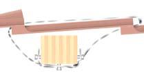
31 SOLAR SYSTEMS INSTALLATION INSTRUCTIONS 1. Before you start installing the solar water heater, please read carefully all the installation instructions stated and illustrated in this manual. 2. Before the installation of the solar water heater, it is very important that the customer and the installer agree on all the details concerning the correct and safe installation of the appliance, (such as location, placement point, static resistance and control of the surface on which the appliance will be placed, piping and wiring run etc). 3. The installation should be done according to the local electric and plumbing regulations. 4. The location you will choose for the installation of the solar collector(s) should not be shaded by any obstacles (trees, buildings...etc.) all around the year. (see obstacle table here below). 5. For optimum performance of the solar system, the collector(s) must face South, for countries located in the Northern hemisphere and North for countries located in the Southern hemisphere. In case that it is not totally possible for the solar collector(s) to face the equator, you must turn it (them) towards East up to 30º if major hot water draw is before 14:00 p.m., or towards West up to 30º if major hot water draw is after 14:00 p.m. The ideal inclination of the solar collector(s) should be equal to the latitude in which the installation is done. 6. The support base of the collector(s) is the same for both flat and inclined roofs. It is diversified only in the way of it s assembly (see installation instructions on the following pages.) 7. If the surface on which the solar collector(s) will be installed (inclined or flat) is not compatible with the standard equipment supplied with each appliance, then alternate equipment must be used. The installer has to choose, propose and install this alternate equipment, always under the concurrent opinion of the customer. 8. For installation on an inclined roof, the «D» plates must be screwed with the appropriate screws and nuts on the roof timber, in order to secure the right and safe installation of the collector(s). 9. In regions subject to heavy snowfalls, rainfall, storms, strong winds, cyclones, tornadoes it is very important to ensure that the supports of the standard equipment are sufficient to withstand the weight of the expected snow or the intensity of the weather conditions. In these cases the collector(s) must be placed in a stable way on the roof and must be tightened with additional metal straps. Latitude Distance between collector and obstacle 0º- 25º X = 1,0 x Y 25º- 35º X = 1,5 x Y 35º- 45º X = 2,0 x Y 45º- 50º X = 2,5 x Y 50º + X = 3,0 x Y HELIOAKMI S.A. reserves the right to change all specifications of the products and their accessories without prior notice. 31
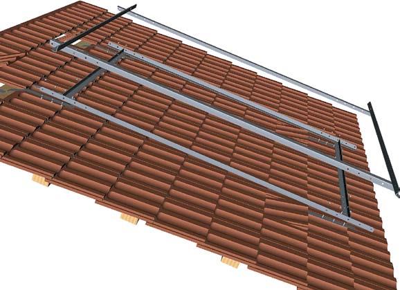
32 INSTALLATION INSTRUCTIONS ASSEMBLY INSTRUCTIONS The same support base is used for both flat and inclined surfaces for the collector models ST-2000 and ST Installation Instructions Attention: the top plate E or C is adjusted after the placement of the collector(s). Place the collector(s) on the support base and secure them with the plates (E) or (C) and tightly screw them onto the plates (B). INSTALLATION ON FLAT SURFACES Connect the plates A, B, C, and D by screwing them tight to each other as shown on the illustrations on the following pages. Loosely screw the bottom plate E onto the plates B. Attention: The top plate E is adjusted after the placement of the collector(s). Level the support base on the flat surface. Place the collector(s) on the support base and then screw it with the moly plugs and the bolts onto the concrete, according to your country s regulations. INSTALLATION ON AN INCLINED SURFACE Connect the plates (A) and (E) so that to form a rectangular frame, on the support bases with one and three collectors while the plates (A) and (C) on the support base with two collectors (as shown on the following pages). Bend the 4 plates (D) as shown in the illustrations. Remove the tiles, and place the bent plates (D) on the wooden timbers or on the concrete of the roof. Screw tightly the rectangular frame (A)+(C) or (E) onto the plates (D). Level the support base and screw the plates (D) onto the wooden timbers of the roof as shown in the illustrations. For the safe installation of the support base you must always use the additional metal straps. Lift the tiles and pass the metal straps under the horizontal wooden timbers of the roof. Tighten them onto the plates (C) for the support base with two collectors or to plates (E) for the support bases with one or three collectors, so that the support base can not move in any direction. Screw the plates (B) onto the rectangular frame (A) + (C) or (E). Ensure that the plates (B) are tightly screwed on the holes of the plate (A). Loosely screw the bottom plate (E) or (C) onto the plates (B). TECHNICAL CHARACTERISTICS OF THE SUPPORT BASE Material: heat dipped galvanized metal plates Thickness: 2,5mm - 3,0mm Form: Angle of 90º, 35mm x 35mm DIMENSIONS OF THE PLATES OF THE SUPPORT BASE A = 2150 mm B = 2150 mm C = 1430 mm D = 1180 mm D = 1220 mm E = 1150 mm E = 1430 mm E = 2355 mm same for all of the support bases For support bases with 1 & 2 collectors For support bases with 3 collectors For support base with 1 collector For support base with 2 collectors For support base with 3 collectors Note: The specifications of the products, their accessories (e.g. electric resistances, thermostats, valves, liquid.etc) and their materials are in accordance with the Greek standards. You must be informed and check if the specifications of the products and their accessories are in accordance with the local and national standards and regulations that apply in your country. The importer/distributor is responsible for the importation, commercialization and installation of the products. HELIOAKMI S.A. in no case is liable for any damages caused to third parties for any reason, such as wrong installation of the appliances and their accessories, from the non-observation of the regulations and lows (electrical, urban planning, plumbing, sanitary etc) applying in your country/area. In case of a defective product apply the terms and conditions of the warranty. HELIOAKMI S.A. reserves the right to change all specifications of the products and their accessories without prior notice. 32


33 INSTALLATION INSTRUCTIONS Support base for 1 collector ST 2000 or ST 2500 (p ) Installation Instructions Support base for 2 collectors ST 2000 or ST 2500 (p ) Support base for 3 collectors ST 2000 or ST 2500 (p ) 33
34 Installation Instructions Assemply diagram of the support base for one collector ST 2500 on a flat or inclined surface HELIOAKMI S.A. reserves the right to change all specifications of the products and their accessories without prior notice. 34


35 Installation Instructions Attention: the plate (A) is connected to the plate (B) exactly as shown in the detailed. 35
36 INSTALLATION INSTRUCTIONS Assemply diagram of the support base for two collectors ST 2500 on a flat or inclined surface HELIOAKMI S.A. reserves the right to change all specifications of the products and their accessories without prior notice. 36

37 INSTALLATION INSTRUCTIONS Attention: for the installation of two collectors on a tiled roof, the plates C are installed in the middle hole of the plates A. Attention: the plate A is connected to the plate B exactly as shown in the detailed diagram 37
38 INSTALLATION INSTRUCTIONS Assemply diagram of the support base for three collectors ST 2500 on a flat or inclined surface HELIOAKMI S.A. reserves the right to change all specifications of the products and their accessories without prior notice. 38


39 INSTALLATION INSTRUCTIONS Attention: in the installation of the support base with three collectors on a tiled roof the three plates C are not used. 39


40 INSTALLATION INSTRUCTIONS For the connection of two and three collectors to each other you must use the bronze connecting raccords as shown in the diagrams. The bronze plugs 1 / 2 are connected diagonally on the collector(s). The bronze cross, the degasser and the sensor socket are connected to the outlet on the highest point of the collector(s) as shown in the photo. In order to achieve the best contact between the the sensor and the sensor socket, use thermal conductive material before connecting. The above accessories are found in a plastic bag which is included in the accessories box. Connection of collectors and accessories Arrangement of connection sensor socket No2 2 The sensor socket (1) of length 135mm is connected to the boiler, while the small sensor socket (2) of length 65mm is connected to the collectors. 1 40

41 INSTALLATION INSTRUCTIONS Connection of collectors and accessories 41
42 Installation Instructions Hydraulic KIT For the connection of the hydraulic kit with the closed circuit (collectors, tube heat exchanger which is located at the bottom part of the boiler) refer to the hydraulic diagram of the solar system on page 30. The connection of the expansion pot with the safety valve of the hydraulic kit must have greatest length of 2 meters, without any corners and without any high air gathering area. The diameter is 3/4. After the plumbing installation, the closed circuit must be cleaned. The cleaning of the system is achieved with water for 15 minutes by isolating the circulator from it s two valves which are located before and after it and by opening the two inlets / outlets of the system. The inlets / outlets have raccords (male) for connection to a plastic pipe. Before the filling of the closed circuit, we must check the watertightness of all of the connections. We can, for instance, during the cleaning, turn-off one of the emptying-filling valves and use a pressure pump or the pressure of the water supply so that we can raise the pressure to 5 bar for 15 minutes. Attention: the expansion pot must be isolated so as to minimize the overload of the maximum functioning pressure. The mixing of the antifreeze liquid must be done before the filling and in accordance to the lowest environmental temperature (see table on page 27). The filling of the system can be done either from the top part of the collector, by the gravity or with a pump from the hydraulic kit. The functioning pressure, between 1,5 and 3 bar, can be achieved with the pressure pump or the pressure of the water supply. We constantly check all of the points of degassing, while filling simultaneously with liquid. All of the installations and connections of the system must be done according to the electric, plumbing, and construction etc regulations applicable in your country. It is recommended that a pail is placed under the hydraulic kit in which water or liquid will be accumulated from the dripping of the safety valve. This is really useful during the filling and degassing or the hydraulic testing since the valve opens at 6 bar. Piping of the closed circuit All of the piping that leave and return from and to the collectors have to be properly insulated so that they can withstand temperatures from -30ºC up to +120ºC. It is also necessary to use an anti-uv (solar radiation) for the insulation. The insulation must have suitable thickness in accordance to the local climatic conditions. The distance between the collectors and the tube heat exchanger of the boiler must be the least possible so as to minimize the thermal losses. Air trapping areas must be avoided. If this is not possible, an automatic degasser must be installed at that point. The diameter of the pipes must be from 18mm - 22mm for distance up to 20m and 15mm for distance down to 12m. All of the connection raccords which will be used must withstand pressure of 6 bar and temperatures between 30ºC and + 200ºC. After the guarantee has expired, it is recommended that a yearly check is made on the installation and the connections. 42
43 Installation Instructions Specification text Is a ready-to-connect solar station for circulation and venting of solar circuit medium with mounting attachments. With integrated SETTER Inline UN regulating and check valve with direct indication of the set flow rate in l/min. Optimized for use in solar applications. Measured values with medium viscosity u = 2.3 mm 2 /s can be read directly atthe sight glass during adjustment without the need for tables, diagrams or measuring devices. Technical data Max. operating temperature: - Flow circuit (venting side): TB 160ºC - Return circuit (pump side): TB 110ºC Max. operating pressure: 8 bar. - Safety valve response pressure: 6 bar K vs value and measurement range as per table «Type Program». Vent pipe: Painted steel Valve housing components: Brass Internal components: Stainless steel, brass and plastic Sight glass: Boric silicate O-ring seals: EPDM Flat seals with high temperature resistance suitable for use in solar applications Insulating material: EPP Thread according to DIN 2999 / ISO 7 and ISO 228 Measuring accuracy ±10% (of the highest nominal value) Fluids Water and proprietary additives used against corrosion and freezing (display scale for medium viscosity u=2.3mm 2 /s) Heating water and cooling water Hydraulic kit Includes: flow phase (venting side) and return phase (pump side) Measurement range 3) kvs 1) kvs 2) Circulation pump 4,0-16,0 l/min 3,3 6,0 WILO ST 20/6-3 1) k vs [m 3 /h] with U=1 mm 2 /s in the return phase (pump side) 2) k vs [m 3 /h] with U=1 mm 2 /s in the fl ow phase (venting side) 3) Visual scale for water/glycol mix with U= 2,3 mm 2 /s Dimensional drawing 1 Male thread ISO 228, G 1 (line from the collector) 2 Male thread ISO 228, G 1 (line to the collector) 3 Male thread ISO 228, G 1 (line to the reservoir) 4 Male thread ISO 228, G 1 (line from the reservoir) 5 Male thread ISO 228, G 3/4 (expansion vessel line) 6 Female thread DIN 2999 / ISO 7, Rp 3/4 (safety valve blow-off line) 43


44 INSTALLATION INSTRUCTIONS HYDRAULIC KIT 44
45 INSTALLATION INSTRUCTIONS ELECTRIC CONNECTIONS ELECTRIC CONNECTIONS For the installation of the differential thermostat, refer the producer s manual which is included in the package. All of the units function with 230V / 50Hz. In the case where an electric resistance is installed, the voltage must be checked. The electric resistances up to 4kW are 1~230 V with thermostat, while for the electric resistances 6kW - 9kW the voltage is 3~400V and the installation of a thermostat is the installer s obligation. The thermostat once installed and adjusted functions automatically on the boiler. According to the needs of the client, the temperature of the water can be adjusted by the installer to lower or higher levels from the original adjustment and between 30ºC - 80ºC. In the case that for some reason the temperature exceeds the tolerated safety level, the safety unit is activated. This is adjusted to be activated when the temperature of the thermostat reaches 100ºC (±10). In the case that this happens, you must determine it s cause. After the water cools down, we can reactivate it manually by pressing the red button. During the transport of the thermostats and during the process of installation avoid the hitting / banging, dropping of the thermostats, because they can cause serious damage to the thermostat with very dangerous consequences to it s operation. The electric installation should be made by a licensed electrician. A faulty electric connection can cause an explosion of the boiler. In the case where the hot water consumption needs are during periods of the day with little or no sunlight, for instance after 17:00 or before 10:00 a.m., the use of a timer is recommended. This will automatically activate the electric resistance and as long as there is a need for hot water. All the connections must conform with the regulations (electrical, plumbing, urbanism and others) that apply in your area. After completing the installation of the system, clean the area where you have worked, fill out the guarantee and send it by registered post to Helioakmi S.A. ELECTRIC CONNECTIONS OF THE ELECTRIC RESISTANCE AND THERMOSTAT* HELIOAKMI S.A. is not responsible for damages to the products or third parties, which arise from the faulty installation of the unit. Resistance ELECTRIC RESISTANCE The technical characteristics can change without prior notification. * For all countries except South Africa 45
46 TROUBLESHOOTING CHECK LIST Instructions to the customer and installer 46 In the case of the malfunction of the system and before contacting the installer, distributor or agent, please have at hand the information on the next page. INSTRUCTIONS OF USE - RECOMMENDATIONS The NOVASUN solar systems do not require the intervention of the user. It is recommended though, that after the first 15 days of functioning, to check the pressure of the closed circuit (collector - boiler) and that the temperatures are at normal levels in relation with the time of the inspection, the sunlight and the «Installation Sheet». After two years of functioning, it is recommended that a program of annual service is begun. If there is a breakage of collector s glass, it must be replaced immediately so that the absorber will not be damaged. If there is a lot of dust in the area, then the glass of the collectors will have to be washed at least twice a year with water, except if it often rains. After the installation is complete, the installer will have to inform the client about the functioning of the system. In the case of any malfunction of the system, we recommend the client to contact the installer since he only knows all of the various parameters and the possible particular characteristics of the installation. IN THE CASE OF MALFUNCTION (Instructions to the installer) Ensure that: The climate conditions permit the functioning of the solar system. There is no shading of the collectors by any obstacles and that they are clean from dust. That there is no leakage in the closed circuit and that all of the connections, raccords, and pipes are tightly screwed and water-tight. That the function of the circulator is correctly programmed. In the case of CAMPINI, the starting differential temperature is programmed by the producer at 10ºC above the temperature of the boiler (6ºC is recommended). Refer to the «Installation Sheet» since the installer might have changed this parameter. The circulator is functioning if the weather conditions allow for it s function. By touching the circulator we can feel the vibrations of the system. Check the electric current on the electric board and if needed contact the electrician of the installation. The mixing valve for hot / cold water in the outlet of the boiler is correctly adjusted and is functioning. The pressure of the closed circuit (indication of the manometer on the hydraulic kit) is the same, with the one described on the «Installation Sheet» (around bar). If you can, for the immediate function of the system, fill it with antifreeze liquid and water from the water supply or properly adjust the automatic filling, up to the pressure indicated on the «Installation Sheet». That there is enough liquid in the closed circuit of collectors-boiler. In days with intense sunlight and normal function of the circulator, the highest points of the pipes must be warm, (for example - top outlet of the collector). Be careful to the false warmth which might be caused from the direct sunlight There is gas in the expansion pot (if needed check for pre-pressure air only with empty installation as stated on the «Installation Sheet», and that the safety valve has not opened. Note: All the connections and the installations must be done according to the regulations (electrical, plumbing, urbanism and others) that apply in your area.
47 TROUBLESHOOTING CHECK LIST INSTRUCTIONS FOR THE INSTALLER (Filled out by installer, sent to manufacturer) After the installation is complete, the installer with the help of the check list below has to check all of the points which are noted and mark in the relevant column if it has been correctly done with YES or NO. LIST COLLECTORS AND EXTERNAL PIPING Is the installation and the fixing of the support base according to the instructions and local regulations? Is there an ideal location and facing of the collectors? Is there humidity inside the collectors? Is water allowed to flow under the collectors? Are the hydraulic connections of the collectors correct? Has the function and installment of the sensor on the collectors been done correctly? Has there been good UV protection on the thermal insulation? Has there been good insulation of all the piping? Has the installment on the roof been done according to the local regulations? PRIMARY CIRCUIT (SOLAR) Does the inclination of the pipes allow the degassing from the highest point? Does the closed circuit have the right pressure? Are there any leaks in the closed circuit, the connections, or in the tube heat exchanger? Is there a manometer in the closed circuit of the collectors? Is the loading valve installed properly? Was a non-return valve installed? Was a discharge valve installed in the lowest points? Does a reseptacle exist for the leaking of liquid or thermal fluid / water? Is there a safety valve connected? Is there an indication of the make and type of thermal liquid on a label installed in a viewable area? DIFFERENTIAL THERMOSTAT ELECTRIC CONNECTIONS Is the differential thermostat programmed for the right temperatures? Does the differential thermostat function properly? Is the maximum temperature of the boiler adjusted properly? (if a mixing valve has not been installed for hot / cold water at the outlet of the boiler) Have the sensors of the boiler and collectors been properly connected? Do the sensors of the boiler and collectors function properly? Are the electric cables properly fixed? Has the electric connection been done according to the local regulations? (insulation, grounding, etc ) BOILER AND HOT WATER CIRCUIT Is the electric resistance connected properly? (if it exists) Does a mixing valve of hot / cold water exist? Is the insulation of the boiler in good condition? Is the safety valve connected to the sewer? GENERAL Was the guarantee properly filled and given to the client? Were the instructions of use given to the client? Was the proper selection of the model made according to the needs of the client? Was the client informed with the other choices that exist for the production of hot water? This check list must be sent along with the guarantee to the manufacturer HELIOAKMI S.A., Nea Zoi, Aspropyrgos Attiki, Greece Personal data of the installer: Full name... Address... Telephone.... YES NO Personal data of the distributor or agent: Full name... Address... Telephone.... Signature of installer:... 47
48 TROUBLESHOOTING CHECK LIST INSTALLATION SHEET (Filled out by installer, kept by client) Full name of client... Address / Telephone... Model.... Date of Installation Installation of the collectors (tiled roof, flat roof, other)... Collectors facing : South East West Inclination of the collectores...(in ºC) Characteristics of plumbing Test pressure of the closed circuit....(bar) Test pressure of the expansion pot (nitrogen)....(bar) Relation of glicol (%) water...(%) glicol Existence of automatic filling... YES / NO Initial filling with pump...yes / NO Electric characteristics / adjustment of differential thermostat Model of Differential Thermostat Adjustment of maximum temperature for the protection of the boiler...(ºc) Adjustment of starting differential temperature...(ºc) Adjustment of the hysteresis temperature...(ºc) Adjustment of antifreeze protection...(ºc) Description of the electric connection of the circulator (for example: direct in the differential thermostat or use of electric board with safety switch especially for the circulator). General comments: Personal data of the installer: Full name... Address... Telephone... Personal data of the distributor or agent: Full name... Address... Telephone... 48
49 NOTES 49
50 NOTES 50
51 NOTES 51

52 Helioakmi S.A., Nea Zoi, 19300, Aspropyrgos, AttiKI, GrÈce Tel.: (+30) , Fax: (+30) web-site: note: HELIOAKMI S.A. reserves the right to change all specifications of the products and their accessories without prior notice.
TECHNICAL MANUAL INSTALLATION, MAINTENANCE AND USE INSTRUCTIONS
 TECHNICAL MANUAL INSTALLATION, MAINTENANCE AN USE INSTRUCTIONS ENGLISH ear Friends, This is our first attempt to communicate with you in this manner, where writing becomes a friendly chat. Through the
Solar heating systems
 03 energy efficiency Compact, "ALL-IN-ONE" solar system Solar panel for swimming pools Hydraulic components Drain-Unit: dual hydraulic unit with drain back system Drain-Unit: hydraulic unit with drain-back
Installation and operation instructions Solar stations SolarBloC midi Premium DN 20 SolarBloC maxi Premium DN 25
 PAW GmbH & Co. KG Böcklerstr. 11, D-31789 Hameln, Germany Phone: +49-5151-9856-0, Fax: +49-5151-9856-98 E-mail: info@paw.eu, Web: www.paw.eu Installation and operation instructions Solar stations SolarBloC
Components for solar heating systems
 solarorkli Components for solar heating systems Components for heating and plumbing Components for solar heating systems Manifolds and distribution equipment Thermostatic valves Manual valves Motorised
INDIRECT SYSTEM FOR FROST LOCATIONS
 SOLAR WATER HEATING INDIRECT SYSTEM FOR FROST LOCATIONS EFFICIENT USE OF NATURAL SOLAR ENERGY FROM THE DOMESTIC SOLAR WATER HEATERS WITH SOLAR COLLECTOR PANELS & SOLAR VACUUM TUBES Solar Water Heaters
USER MANUAL INSTALLATION INSTRUCTIONS WARRANTY REGISTER
 USER MANUAL INSTALLATION INSTRUCTIONS WARRANTY REGISTER GREENGLO MAINS PRESSURE INTEGRATED WATER HEATER SINGLE COIL SERIES & DOUBLE COIL SERIES GREENGLO SAVER Customer Congratulations for choosing a GreenGlo
RENEWABLE ENERGY THERMAL SOLAR ENERGY. RENEWABLE ENERGY...pag. 05
 THERMAL SOLAR ENERGY CATALOGUE OCTOBER 2008 INDEX RENEWABLE ENERGY THERMAL SOLAR ENERGY RENEWABLE ENERGY...pag. 05 SISTEMA CS 25 RN TAU... pag. 6 SISTEMA CS 25 RN - CS 25 RN PLUS... pag. 8 SISTEMA CSL
Solar water heating system
 Solar water heating system Perhaps the most popular application of solar systems is for domestic water heating. The popularity of these systems is based on the fact that relatively simple systems are involved
SOLAR WATER HEATING DIRECT SYSTEM FOR FROST-FREE LOCATIONS DOMESTIC SOLAR WATER HEATERS, SOLAR COLLECTOR PANELS & SOLAR VACUUM TUBES
 SOLAR WATER HEATING DIRECT SYSTEM FOR FROST-FREE LOCATIONS DIRECT DOMESTIC SOLAR WATER HEATERS, SOLAR COLLECTOR PANELS & SOLAR VACUUM TUBES Solar Heaters - Close Coupled & Split - Direct System direct
SECTION (15486) - FUEL-FIRED, DOMESTIC WATER HEATERS
 - FUEL-FIRED, DOMESTIC WATER HEATERS") SECTION 22 34 00 (15486) - FUEL-FIRED, DOMESTIC WATER HEATERS System shall provide a complete hot water return throughout the entire system with balancing (flow control) valves not less than 10 feet from
SECTION 22 34 00 (15486) - FUEL-FIRED, DOMESTIC WATER HEATERS System shall provide a complete hot water return throughout the entire system with balancing (flow control) valves not less than 10 feet from
Frequently Asked Questions Solar Collector G24
 Frequently Asked Questions Solar Collector G24 The installation and use of the collector is very simple. Here we have tried to answer the questions we get very comprehensively, for those who would like
1 Exam Prep Solar Water and Pool Heating Manual (UCF) Questions and Answers (Plumbing Contractor)
 Questions and Answers (Plumbing Contractor)") 1 Exam Prep Solar Water and Pool Heating Manual (UCF) Questions and Answers (Plumbing Contractor) 1. For year-round use, a collector tilt of degrees works best for a project located in Tampa, Florida.
1 Exam Prep Solar Water and Pool Heating Manual (UCF) Questions and Answers (Plumbing Contractor) 1. For year-round use, a collector tilt of degrees works best for a project located in Tampa, Florida.
October Solar Thermal
 October 2018 Solar Thermal Clima&Comfort RESIDENTIAL Settembre 2018 1 SOLAR THERMAL ERP Product in compliance with EU Regulations on Ecodesign* and Energy Labelling * Minimum efficiency limits on global
D O M E S T I C Solar Thermal
 DOMESTIC H E A T I N G Solar Thermal October 2017 SOLAR THERMAL ERP PRODUCT IN COMPLIANCE WITH EU REGULATIONS ON ESIGN* AND ENERGY LABELLING * Minimum efficiency limits on global primary energy consumption
SOLAREKS. Natural Circulated Closed Loop System SOLAREKS
 SOLAREKS Natural Circulated Closed Loop System SOLAREKS Tel: 0090 216 3148580 Fax: 0090 216 3641029 E-mail: info@solareks.com Index A. General Information 1. Product Description 2. Product Use 3. About
TECHNICAL MANUAL INSTALLATION, MAINTENANCE AND USE INSTRUCTIONS
 TECHNICAL MANUAL INSTALLATION, MAINTENANCE AN USE INSTRUCTIONS ENGLISH ear Friends, This is our first attempt to communicate with you in this manner, where writing becomes a friendly chat. Through the
GFT-060/40/H2. Designed and built According AD-2000 regulation Homologation and branded CE According to the European Directive CE
 Item 1) TWO THERMAL OIL HEATERS OF 1200 kw EACH 1.1) THERMAL OIL HEATER BODY Brand PIROBLOC Model GFT-060/40/H2 Power 1200 kw Delta Temperature 40 ºC Execution Horizontal Designed and built According AD-2000
General System Layout Sketch
 General System Layout Sketch EZ-37 Solar Panels PV panel Glycol Fill Valve Expansion Tank ` 1 Introduction This document describes how to install a Heliatos GH type solar water heating system. These systems
CodeNotes. Solar Water Heating Systems Based on the 2018 International Solar Energy Provisions (ISEP ) Introduction OFFICIAL
 Introduction OFFICIAL") CodeNotes is provided courtesy of the ICC PMG Official Membership Council OFFICIAL CodeNotes Solar Water Heating Systems Based on the 2018 International Solar Energy Provisions (ISEP ) Introduction Solar
CodeNotes is provided courtesy of the ICC PMG Official Membership Council OFFICIAL CodeNotes Solar Water Heating Systems Based on the 2018 International Solar Energy Provisions (ISEP ) Introduction Solar
CHGV AIR COOLED WATER CHILLER WITH HYDRAULIC EQUIPMENT AIR / WATER 47 to 78 kw
 TECHNICAL INSTRUCTIONS CHGV AIR COOLED WATER CHILLER WITH HYDRAULIC EQUIPMENT AIR / WATER 47 to 78 kw CHGV CHGV 64 CHGV 72 CHGV 80 PHRV heat pump model also available May 2006 10 12 167 - GB - 00 MARKING
AGUAdens TM 100% residential condensing D.H.W. wall-mounted water heaters ( litres) AISI 316 D.H.W. WORKING PRESSURE TITANIUM CONDENSING
 AISI 316 D.H.W. WORKING PRESSURE TITANIUM CONDENSING") MADE IN ITALY residential condensing D.H.W. up to 10 bar WORKING PRESSURE AISI 316 Ti TITANIUM D.H.W. 100% CONDENSING AGUAdens TM wall-mounted water heaters (16-22 -37 litres) AGUAdensTM INSTANTANEOUS
MADE IN ITALY residential condensing D.H.W. up to 10 bar WORKING PRESSURE AISI 316 Ti TITANIUM D.H.W. 100% CONDENSING AGUAdens TM wall-mounted water heaters (16-22 -37 litres) AGUAdensTM INSTANTANEOUS
Thermostatic valve bodies
 Thermostatic valve bodies for single pipe heating systems Thermostatic valves with radiator connection systems IMI HEIMEIER / Thermostatic heads and Radiator valves / Thermostatic valve bodies for single
Solar Thermal Energy
 Solar Thermal Energy INDEX Residential Applications Flat Plate Solar Collectors... 5 SOL 200 and SOL 200 H... 7 Mediterráneo 200... 8 Mediterráneo SLIM 200... 9 Hydraulic fittings and mounting systems...
union swing check valve spring loaded check valve purging valve pressure relief valve relief valve metered balancing valve
 VENT APPENDIX A: PIPING SYMBOL LEGEND GENERIC COMPONENTS CALEFFI COMPONENTS circulator circulator w/ ThermoBloc union circulator w/ swing check spring loaded balancing balancing w/ gate check globe s purging
INSTALLATION MANUAL. Domestic hot water tank for air to water heat pump system EKHWE150A3V3 EKHWET150A3V3 EKHWE200A3V3 EKHWE300A3V3
 INSTALLATION MANUAL Domestic hot water tank for air to water heat pump system EKHWE50AV EKHWET50AV EKHWE00AV EKHWE00AV EKHWE00AZ EKHWE00AZ 4 5 6 7 x x x 4x x x x EKHWE50~00 EKHWET50 50 50 0 0 00 50 700
Soak in the Sunshine. Solar Hot Water
 Soak in the Sunshine Solar Hot Water Soak in the sunshine, and SAVE with solar hot water from Chromagen USES UP TO 80% LESS ENERGY With a solar hot water system from Chromagen, you can literally soak in
Valves, controls + systems. Innovation + Quality. Stations for solar energy and solid fuel boilers Product range
 Valves, controls + systems Innovation + Quality Stations for solar energy and solid fuel boilers Product range Stations for solar energy and solid fuel boilers Content Page Summary Stations for solar energy
CodeNotes. Solar Water Heating Systems Based on the 2015 International Solar Energy Provisions. Introduction. Solar Water Heating System Designs
 CodeNotes is provided courtesy of the ICC PMG Official Membership Council CodeNotes Solar Water Heating Systems Based on the 2015 International Solar Energy Provisions Introduction Solar water heating
Brown University Revised August 3, 2012 Facilities Design & Construction Standards SECTION AIR HANDLING UNITS
 SECTION 23 70 00 AIR HANDLING UNITS PART 1. GENERAL 1.1 Section includes air-handling units to 15,000 cfm and accessories. 1.2 Related Sections 1 : A. Division 01 - Brown University Standard for Narragansett
SOLAREKS. Natural Circulated Open Loop System SOLAREKS
 SOLAREKS Natural Circulated Open Loop System SOLAREKS Tel: 0090 216 3148580 Fax: 0090 216 3641029 E-mail: info@solareks.com.tr Index A. General Information 1. Product Description 2. Product Use 3. About
The heart of electric appliances ELECTRIC WATER HEATING MADE IN ITALY
 The heart of electric appliances ELECTRIC WATER HEATING MADE IN ITALY The heart of electric appliances MADE IN ITALY thermowatt.com 2 THERMOSTATS RTM 07 RTS 08 RTS PLUS 09 RTS ERP / RTS PLUS ERP 10 TES
TECHNICAL MANUAL HYPERION. Solar water heaters. Installation, maintenance & use instructions
 TECHNICAL MANUAL Solar water heaters HYPERION Installation, maintenance & use instructions HYPERION CONTENTS DOMESTIC HOT WATER CONSUMPTION... 4 SOLAR WATER HEATER OPERATION - WATER HEATING... 4 SOLAR
Installation, Operation and Maintenance Instructions for Thermax Semi-Storage Calorifier
 OM001 Installation, Operation and Maintenance Instructions for Thermax Semi-Storage Calorifier These operating and maintenance instructions are for standard semi-storage calorifiers (vessels fitted with
NEW. Thermotank Quadroline. living full of energy. The new generation of plastic storage tanks. Energy systems
 NEW Energy systems Thermotank Quadroline The new generation of plastic storage tanks living full of energy Water provides a vital basis for life. It transfers heat in an environmentally friendly way and
S SOLAR RANGE
 GB S 002-02 SOLAR RANGE Solar collectors for on-roof installation Solar collectors for in-roof installation Roof mounting systems for on-roof installation Roof mounting systems for in-roof installation
Safety vacuum drying oven for flammable solvents
 VDL series 53 Vacuum drying ovens Safety vacuum drying oven for flammable solvents A BINDER safety vacuum drying oven of the VDL series ensures maximum safety when drying organic solvents standard with
CHGV AIR COOLED WATER CHILLER WITH HYDRAULIC EQUIPMENT AIR / WATER 21 to 39 kw
 TECHNICAL INSTRUCTIONS CHGV AIR COOLED WATER CHILLER WITH HYDRAULIC EQUIPMENT AIR / WATER 21 to 39 kw CHGV 22 CHGV 2 CHGV 32 CHGV 40 PHRV heat pump model also available September 2007 10 12 11 - GB - 02
Installation, Operating and Servicing Instructions
 EN 0 / 0 / 00 / 800 Installation, Operating and Servicing Instructions excellence in hot water EN Y000.D EN INDEX Warnings Who should read these instructions Symbols Recommendations Applicable standards
CHGV AIR COOLED WATER CHILLER WITH HYDRAULIC EQUIPMENT AIR / WATER 47 to 78 kw
 TECHNICAL INSTRUCTIONS CHGV AIR COOLED WATER CHILLER WITH HYDRAULIC EQUIPMENT AIR / WATER 47 to 78 kw CHGV 50 CHGV 64 CHGV 72 CHGV 80 PHRV heat pump model also available November 2007 10 12 167 - GB -
Operating Guide. Termix Solar A+/B+ 1.0 Table of Contents. 1.0 Table of Contents
 1.0 Table of Contents 1.0 Table of Contents... 1........................................................................ 2 2.0 Functional description... 3 3.0 Safety notes... 4 3.1 Safety Notes general............................................
Commissioning a Solar Thermal Installation
 OPERATING INSTRUCTIONS Wagner& Co Commissioning a Solar Thermal Installation Contents. Solar Circuit... 2. Commissioning... 3 3. Service Information... 4. Maintenance.... Solar Circuit Components Pipework
Installation, Operating and Servicing Instructions
 ENGLISH 0 / 0 / 0 / 0 / 00 Installation, Operating and Servicing Instructions FRANCAIS NEDERLANDS ESPAÑOL Y000.A EN ESPAÑOL NEDERLANDS FRANCAIS ENGLISH INDEX WARNING Who should read these instructions
TESTING FITOTERM FITOCLIMA TEMPERATURE / HUMIDITY CONTROL REACH-IN ENVIRONMENTAL CHAMBERS FOR CLIMATE AND TEMPERATURE TESTING
 FITOTERM FITOCLIMA TEMPERATURE / HUMIDITY CONTROL REACH-IN ENVIRONMENTAL CHAMBERS FOR CLIMATE AND TEMPERATURE FitoTerm & FitoClima temperature and humidity testing chambers offer highly precise and reproducible
TECHNICAL MANUAL Solar water heaters
 TECHNICAL MANUAL Solar water heaters Installation, maintenance & use instructions SOLAR WATER HEATERS CONTENTS GENERAL INFORMATION... DOMESTIC HOT WATER CONSUMPTION... SOLAR WATER HEATER OPERATION - WATER
Products catalogue THERMODYNAMIC SOLUTIONS FOR EFFICIENCY CHALLENGES
 Products catalogue THERMODYNAMIC SOLUTIONS FOR EFFICIENCY CHALLENGES 1 1 2 3 Once again, the Energy Panel team has put all their excitement and enthusiasm to create this new publication. We want to make
Thermostatic valves with radiator connection systems
 Multilux Eclipse Thermostatic valves with radiator connection systems with two-point connection for two-pipe heating systems, with automatic flow limitation IMI HEIMEIER / Thermostatic heads and Radiator
INSTALLATION, COMMISSIONING AND OPERATING MANUAL
 INSTALLATION, COMMISSIONING AND OPERATING MANUAL 1 YTBV-D-CE42_0109 CONTENT Available models and capacities Supplier information Warranty Safety Emergency stops/ shutdowns About this manual Models Physical
Empty unit Cover Water Total weight 15 kg 8 kg 10 kg 33 kg
 DE LUXE Substation Introduction The HERZ DE LUXE Substation is a firmly mounted unit for providing hot water. In contrast to a hot water boiler which heats and then stores the water before it is being
INSTALLATION INSTRUCTIONS GEO PRIME TANK. (Patent Pending) GPC
 GPC") INSTALLATION INSTRUCTIONS GEO PRIME TANK (Patent Pending) GPC Table of Contents General Description 2 Installation 3 Flushing and Purging 5 Initial Start up 7 Adding or Checking Fluid 8 Replacing a Pump
INSTALLATION INSTRUCTIONS GEO PRIME TANK (Patent Pending) GPC Table of Contents General Description 2 Installation 3 Flushing and Purging 5 Initial Start up 7 Adding or Checking Fluid 8 Replacing a Pump
AGS 2 SOLAR PUMP STATION FOR SOLAR DOMESTIC HOT WATER SYSTEMS UK/IE
 INSTRUCTION MANUAL INSTALLATION AND SERVICING AGS 2 SOLAR PUMP STATION FOR SOLAR DOMESTIC HOT WATER SYSTEMS UK/IE About this manual These installation and maintenance instructions contain important information
Immersion heaters for ATEX/IECEx hazardous areas or in non-atex version
 for ATEX/IECEx hazardous areas or in non-atex version * Non contractual picture Warning It is imperative to read these instructions carefully before installing or maintaining the equipment. MI100EN 09/2017
ACCUMULATION OF EUROPEAN CLASS
 ACCUMULATION OF EUROPEAN CLASS Total comfort MODEL nominal output kw minimum output kw DUA PLUS B TN DUA PLUS B TFS natural draught room sealed forced draught 28 12.4 28 12.4 DUA PLUS B was born from the
DENVER PUBLIC SCHOOLS DESIGN AND CONSTRUCTION STANDARDS This Standard is for guidance only. SECTION PUMPS
 PART 0 A/E INSTRUCTIONS 0.01 Design Requirements A. Pumping system design 1. A primary-secondary pumping system is preferred. Redundant pipes are required for chillers and boilers. 2. Select pumps to operate
ALKON CARGO. A precise and fast delivery rate. A very high specific flow rate (20 litres per minute with Dt 25)
") ALKON CARGO ALKON CARGO model Max/min nominal output Heat input condensing Non-condensing η condensation at 30 part load 35 7,4 35,1 6,7 33,5 34,8 106,3 Efficiency class (directive 92/42) ALKON CARGO is
ALKON CARGO ALKON CARGO model Max/min nominal output Heat input condensing Non-condensing η condensation at 30 part load 35 7,4 35,1 6,7 33,5 34,8 106,3 Efficiency class (directive 92/42) ALKON CARGO is
regulux Radiator lockshield with drain-off facility Pressurisation & Water Quality Balancing & control thermostatic control engineering ADVANTAge
 regulux Radiator lockshield with drain-off facility Pressurisation & Water Quality Balancing & control thermostatic control engineering ADVANTAge Regulux Description Separate presetting cone for consistent
TECHNICAL MANUAL HYPERION. Solar water heaters. Installation, maintenance & use instructions
 TECHNICAL MANUAL Solar water heaters HYPERION Installation, maintenance & use instructions SOLAR WATER HEATERS CONTENTS GENERAL INFORMATION... 4 DOMESTIC HOT WATER CONSUMPTION... 4 SOLAR WATER HEATER
Remeha. Fuel oil/gas boilers P 520. Installation and Service Manual A
 Remeha Fuel oil/gas boilers EN Installation and Service Manual 300016859-001-A 63115 Declaration of conformity The appliance complies with the standard model described in declaration of compliance. It
Advance Split
 Engineering Data Manual Aqu@Scop Advance Split Air-to-Water DC Inverter Split Heat Pumps Models 005, 008, 012 & 014 2 to 16 kw Strength Points Most efficient heating technology with variable speed compressor.
SOLAR HEATING SYSTEMS
 introducing SOLAR HEATING SYSTEMS TM the low carbon water heating system June 2008 Irl 1 In this environmentally challenging world, it s time to rethink our heating.....while we still have time. There
FITOCLIMA ECV45 / ECV75 TEMPERATURE & HUMIDITY TEST CHAMBER INTEGRATION WITH ELECTRO-DYNAMIC SHAKER
 FITOCLIMA 1.000 ECV45 / ECV75 TEMPERATURE & HUMIDITY TEST CHAMBER INTEGRATION WITH ELECTRO-DYNAMIC SHAKER INTEGRATED CLIMATIC AND VIBRATION FitoTerm & FitoClima temperature and humidity testing chambers
COMMERCIAL SOLAR SOLUTIONS
 Worldwide experience Biggest range of options Total package solutions 52 Commercial Solar NPT200 collectors provide hot water to Urbanest Student Accommodation Cleveland Street, Redfern NSW COMMERCIAL
Cylinders for Domestic Purposes Heat Pumps
 Testing of Cylinders for use with heat pumps HWA 002:2015 Page 1 of 10 HOT WATER ASSOCIATION SPECIFICATION HWA 002:2015 Cylinders for Domestic Purposes Heat Pumps Specification of requirements and test
Standard. thermostatic valve body without presetting
 Standard thermostatic valve body without presetting Pressurisation & Water Quality Balancing & Control Thermostatic Control EnGInEErInG advantage The standard thermostatic valve bodies are used in two-pipe
with respect to the environment PRICE LIST 2014/15
 with respect to the environment ALFA series SIGMA series FORCED CIRCULATION SYSTEMS ELECTRIC WATER HEATERS 3 3 3 ALFA series CONTENTS ALFA - CLOSED LOOP Solar water heaters, Solar water heater boilers,
VITOSOL. Solar hot water heating systems Flat plate and vacuum tube solar collectors
 VITOSOL Solar hot water heating systems Flat plate and vacuum tube solar collectors Solar energy can account for up to 70% or more of the energy required to heat the domestic hot water of an average family
Installation Instructions
 Installation Instructions Solar Collector Kit Solar Collector Add On Kit WARNING: Plumber Be Aware Use copper pipe ONLY. Plastic pipe MUST NOT be used. It is a requirement of a solar water heater installation
Vacuum drying oven for non-flammable solvents
 VD series 53 Vacuum drying ovens Vacuum drying oven for non-flammable solvents A BINDER vacuum drying oven of the VD series is impressive while gently drying with its homogeneous temperature distribution.
Wood gasification process...3. Wood as a fuel...3. Boiler construction - its elements...4
 Wood gasification process... Wood as a fuel... Boiler construction - its elements...4 Boiler construction - materials...4 EKO advantages...4 Boiler construction - schematics... Boiler dimensions... Boiler
Installation and operating instructions. DK energy storage and DK energy buffer
 Installation and operating instructions DK energy storage and DK energy buffer Edition: 08-2015 1 Preliminary note With this DK energy storage / DK energy buffer you purchased a DK quality product. The
D. NEMA Compliance: Provide electric motors and components which comply with NEMA standards.
 PART 1: GENERAL 1.01 Purpose: A. This standard is intended to provide useful information to the Professional Service Provider (PSP) to establish a basis of design. The responsibility of the engineer is
Isotemp. Improve the productivity of your laboratory with accurate, efficient temperature control products from Fisher Scientific.
 Isotemp Bath Circulators and Chillers Improve the productivity of your laboratory with accurate, efficient temperature control products from Fisher Scientific. Choose the temperature control option that
NEWS 2017 SANIFLO. Pumps and pumping stations
 NEWS 2017 SANIFLO Pumps and pumping stations SFA, WORLD LEADER IN SANITARY FACILITIES MADE IN FRANCE For 60 years, the Société Française d Assainissement [French Sanitation Company] has worked on improving
TECHNICAL MANUAL Solar water heaters
 TECHNICAL MANUAL Solar water heaters Installation, maintenance & use instructions SOLAR WATER HEATERS CONTENTS GENERAL INFORMATION... 4 DOMESTIC HOT WATER CONSUMPTION... 4 SOLAR WATER HEATER OPERATION
Reinventing Energy Efficiency
 Commercial WATER2AIR EC LARGE SERIES Reinventing Energy Efficiency www.fhp-mfg.com Environmental stewardship is a core philosophy for FHP Manufacturing from design to production to the reduction in our
Fincoil FMP and FMPG. Air coolers and liquid circulated air coolers
 Fincoil FMP and FMPG coolers and liquid circulated air coolers FMP air coolers and FMPG liquid circulated air coolers are designed for cold rooms where low profi le dual discharge air cooler is needed.
Installation Instructions
 Installation Instructions Collector Kit Collectors with Screwed Fittings NPT200 SOLAR COLLECTOR WARNING: Plumber Be Aware Use copper pipe ONLY. Plastic pipe MUST NOT be used. It is a requirement of a solar
flue pipes flue pipes
 Dinamo Hit is private owned company which exists on the market since 1987. Its main business is production of household electrical gadgets. It is located in the city of Veles, Macedonia. General production
Adelaide Homes Design Guide 4 - Winter warming
 Adelaide Homes Design Guide 4 - Winter warming Adelaide's temperate climate means home warming is required during winter. There are many efficient heating systems. The most economical method, however,
SOLAR HOT WATER HEATERS
 ALTERNATIVE ENERGY SOLAR HOT WATER HEATERS Solar Hot Water The shallow water of a lake is usually warmer than the deep water. That's because the sunlight can heat the lake bottom in the shallow areas,
Retrofit an evacuated tube collector to an existing cylinder Updated
 Run On Sun Australia Retrofit an evacuated tube collector to an existing cylinder Updated 2-8-2018 To contact Run On Sun Australia Pty Ltd Phone Andrew on (02) 6734 6322 Email: andrew@runonsun.com.au Website:
General System Layout Sketch
 General System Layout Sketch EZ-37 Solar Panels PV panel Can use Standard Copper, CPVC or PEX Pipes Pump Existing Water Heater Bottom Feed Connector 1 Introduction This document describes how to install
SG-WS type EXCHANGERS FOR TAP WATER HEATING ELECTRIC STORAGE TAP WATER HEATERS GUARANTEE CERTIFICATE. volume: 80, 100, 120, 140, 200, 300 and 380 dm 3
 GUARANTEE CERTIFICATE Date of assembly Stamp and signature of the fitter GUARANTEE VOUCHER 1 GUARANTEE VOUCHER 2 GUARANTEE VOUCHER 3 GUARANTEE VOUCHER 4 GUARANTEE VOUCHER 5 Cat. no. Factory no. Date of
Operating Guide. Termix Compact 28 VX-FI / HWP / HWS. 1.0 Table of Contents. 1.0 Table of Contents
 1.0 Table of Contents 1.0 Table of Contents... 1........................................................................ 2 2.0 Functional description... 3 3.0 Safety notes... 4 3.1 Safety Notes general............................................
Germany 44% Spain 9% Italy 9% France 8% Austria 7% Greece 6% Poland 2% Belgium 2% Portugal 2% Switzerland 2% Great Britain 2% Cyprus 2%
 SOLAR THE RANGE SAVING Solar energy... SOLAR MARKET IN EUROPE GR AT PL OTHER CY COUNTRIES GB CH PT BE FR IT D ES Germany 44% Spain 9% Italy 9% France 8% Austria 7% Greece % Poland 2% Belgium 2% Portugal
PLEASE LEAVE THIS MANUAL WITH THE OSO UNIT AFTER INSTALLATION INSTALLATION MANUAL
 PLEASE LEAVE THIS MANUAL WITH THE OSO UNIT AFTER INSTALLATION SOLARCYL IM/SC INSTALLATION MANUAL This manual gives detailed advice for installation and should be read carefully prior to fitting any unvented
Cooling and heating systems. Static cooling ceiling system SKS-5/3 for visible installation
 Cooling and heating systems Static cooling ceiling system SKS-/3 DS 10 E 01.010 Static cooling ceiling system SKS-/3 Main features Preliminary remarks / Applications 3 Main dimensions and materials 3 Construction
Thermostatic mixing valves with interchangeable cartridges
 www.caleffi.com R37. Thermostatic mixing valves with interchangeable cartridges Installation, commissioning and servicing instructions 3 Series Function The thermostatic mixing valve is used in systems
The ultimate in air handling units: directly and indirectly fired
 AHU The ultimate in air handling units: directly and indirectly fired Mark has developed a range of air handling units with several options for a wide variety of applications. From a simple air intake
Divacondens D Plus Atmospheric condensation wall-mounted boilers, with instant domestic hot water production
 Divacondens D Plus Atmospheric condensation wall-mounted boilers, with instant domestic hot water production THE SIMPLEST SOLUTION FOR A CONDENSING BOILER DIVACONDENS D PLUS is the generator of condensation
SHERPA DHW 75. Th e multifunctional air-water split heat pump. COP > 4 DHW 75 C
 SHERPA Th e multifunctional air-water split heat pump. PATENTED TECHNOLOGY The combination of an inverter air-water heat pump together with a water-water heat pump allows heating/ and high temperature
INSTALLATION, OPERATION AND MAINTENANCE. Ariterm Vedo
 INSTALLATION, OPERATION AND MAINTENANCE Ariterm Vedo CONTENTS General...3 Installation...4-5 Laddomat 21 Connection diagram...6 Temperature control valve...7 About burning wood...8 Operation...9-11 Service
Installation Manual. Instrucciones de instalación y manual de usuario 1
 Installation Manual Instrucciones de instalación y manual de usuario 1 Installation instructions and user manual V8 2 INDEX 1 GENERAL SAFETY WARNINGS... 4 2 OPERATING PRINCIPLE... 5 3 TECHNICAL FEATURES...
Design-Edition. Design-Edition Thermostatic valves and lockshields, sets
 Design-Edition Design-Edition Thermostatic valves and lockshields, sets IMI HEIMEIER / Design-Edition / Design-Edition Design-Edition The sets are an elegant solution for e. g. design radiators. A sublime
Products catalogue THERMODYNAMIC SOLUTIONS FOR EFFICIENCY CHALLENGES
 Products catalogue THERMODYNAMIC SOLUTIONS FOR EFFICIENCY CHALLENGES 1 2 3 Heat Merchants have partnered with Energy Panel to offer the most advance technology in Thermodynamic Solar Systems for both residential
PANDORA HEAT BANKS OXFORD BROOKES, HARCOURT HILL. Operation and Maintenance. THERMAL INTEGRATION LTD. Tel: Internet:
 PANDORA HEAT BANKS OXFORD BROOKES, HARCOURT HILL Operation and Maintenance THERMAL INTEGRATION LTD. Tel: 0845 2411441 Internet: www.heatweb.com Introduction The District Pandora Heat Bank provides hot
Inta City Shower Mixing Valve CT20010CP
 Inta City Shower Mixing Valve CT20010CP Installation and Maintenance Instructions In this procedure document we have endeavoured to make the information as accurate as possible. We cannot accept any responsibility
Duct heaters for ATEX/IECEx hazardous areas or in non-atex version
 for ATEX/IECEx hazardous areas or in non-atex version * Non contractual picture Warning It is imperative to read these instructions carefully before installing or maintaining the equipment. MI200EN 09/2017
Industrial and collective. With coil exchanger. Technical data. Initial heat-up. surface area. Exchanger. Exchanger capacity.
 Industrial and collective Calorifiers and Combi With coil A compact, safe solution for producing hot water from multiple energy sources, including solar energy. Operation Semi-instantaneous hot water production
GRUNDFOS DATA BOOKLET. Grundfos COMFORT. Circulator pumps. 50/60 Hz
 GRUNDFOS DATA BOOKLET Circulator pumps 50/60 Hz 2 Product range 2. Product range UP(S) COMFORT, 50/60 Hz Pump type 24-hour timer Supplied with Dimensions Accessories Data sheet Thermostat Isolating valve
521 Series. MixCal adjustable three-way thermostatic mixing valve. Installation, commissioning and service instructions
 MixCal adjustable three-way thermostatic mixing valve 37. www.caleffi.com Copyright 15 Caleffi 51 Series Installation, commissioning and service instructions Function The Caleffi MixCal three-way thermostatic