INSTALLATION, OPERATION, AND MAINTENANCE MANUAL FOR ELECTRIC TANKLESS WATER HEATERS SPECADVANTAGE SAFE ADVANTAGE
|
|
|
- Edwin Lee
- 5 years ago
- Views:
Transcription

1 INSTALLATION, OPERATION, AND MAINTENANCE MANUAL FOR ELECTRIC TANKLESS WATER HEATERS SPECADVANTAGE SAFE ADVANTAGE
2

3 IMPORTANT SAFETY INFORMATION READ ALL INSTRUCTIONS BEFORE USING DANGER Indicates an imminently hazardous situation which, if not avoided, will result in death or serious injury. WARNING Indicates a potentially hazardous situation which, if not avoided, could result in death or serious injury. CAUTION Indicates a potentially hazardous situation which, if not avoided, may result in minor or moderate injury. Hot water can be dangerous. There is a high scald potential if the thermostat is set too high. Water temperatures over 125 F (51 C) can cause severe burns or scalding resulting in death. Hot water can cause first degree burns with exposure for as little as: 3 seconds at 140 F (60 C) 20 seconds at 130 F (54 C) 8 minutes at 120 F (48 C) i
4 IMPORTANT SAFETY INFORMATION READ ALL INSTRUCTIONS BEFORE USING 1. You must read and follow all instructions. Serious bodily injury or death could occur if you ignore this warning. 2. All circuit breakers and/or disconnect switches servicing the heater must be turned off when installing, uninstalling, or repairing this water heater. 3. The unit must be installed by a licensed electrician and plumber. 4. The unit must be wired in accordance with the current version of the National Electrical Code (US) or Canadian Electric Code (Canada). 5. This installation must comply with all national, state, and local plumbing and electrical codes. 6. When the heater is not within sight of the electrical circuit breakers, an additional local means of disconnection of all ungrounded conductors must be provided that is within sight of the appliance or a circuit breaker lockout must be used. (Ref. NEC ) 7. Per UL 499, this water heater is not required to be installed with a Temperature and Pressure relief valve (T&P). However, local codes may vary. In case a T&P relief valve is required, it must be installed on the outlet hot water line heater between the heater and the isolation valve. 8. If the Eemax Tank less Water Heater is installed in a location where water damage could occur in the event of a leak, it is recommended that a drip pan be installed and connected to a suitable drain. Alternatively, an active water leak detector and shut off valve can be installed to turn off your water supply in the event a leak is detected. 9. If water supply has a high mineral content, a water softening system is recommended. Damage to the water heater resulting from scale or hard minerals will not be covered under warranty. ii
5 IMPORTANT SAFETY INFORMATION READ ALL INSTRUCTIONS BEFORE USING 10. When the heater is installed in a well water system or if the plumbing system is prone to introducing air into the heater, it is highly recommended that an air separator be installed in the cold water feed to the heater to avoid possible failure of the heating element and/or heating chamber. 11. In accordance with NEC guideline, this water heater is designed for a continuous duty cycle of 3 hours at 100% power output. Exceeding this rating could damage the heater and void the warranty 12. Provide your heater with potable, uninterrupted supply of water at a constant minimum pressure of 35PSI (based on model) and maximum pressure of 150 PSI. 13. Use of Water Hammer Arrestors in applications with excess pipe lengths or fast acting valves strongly recommended, neglecting to do so will damage the heater and void the warranty 14. This heater must be in a location where it is not subject to freezing temperatures unless supplied with factory installed freeze protection 15. Properly purge air out of system before power is applied. Recommended to purge water through system for minimum 2 minutes at a minimum 15 gpm, closing and opening drain valve 3 times to move any lodged air before power is applied. 16. Sanitation models used in a circulator system, a 30 second factory set delay program will be installed to establish flow before power is applied. Contact Eemax for information Applications with the use of a recirculation circulator must be installed according schematics. 18. The use of Ethylene glycol antifreeze is strictly prohibited. Propylene Glycol is the only recommended antifreeze iii
6 iv
7 TABLE OF CONTENTS PERFORMANCE FEATURES... 1 OPERATION PRINCIPLE... 3 MOUNTING THE HEATER TO THE WALL... 4 ELECTRICAL HOOKUP... 5 PLUMBING HOOKUP... 7 COMMISSIONING THE WATER HEATER MONITORING & PREVENTIVE MAINTENANCE CONTROL FEATURES TROUBLESHOOTING PROCEDURES TECHNICAL SUPPORT APPLICATIONS SCHEMATICS WIRING SCHEMATICS v
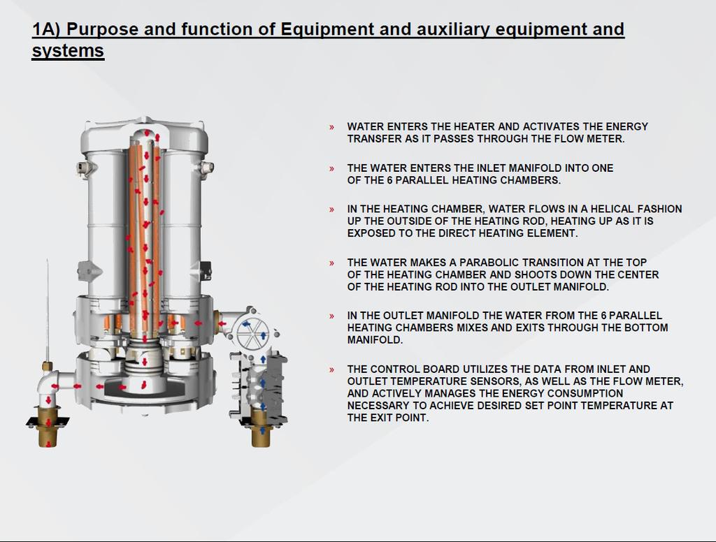
8 PERFORMANCE FEATURES Heating Technology Field Replaceable, non-ferrous, lead-free cartridge-style direct heating element Safety and Reliability Thermo-Optical sensor for protection against entrained air or improper commissioning Materials and Construction NSF-61 listed materials of construction Control and Consumption Active energy management to ensure optimal application of energy based on real-time system demands Multistage element turn-on Visual user interface for field programming Turn-on Flow Rate Integrated high-capacity flow meter Field adjustable maximum activation flow rate (minimum activation flow rate factory set and is not field adjustable.) Pressure Rating Operating pressure range not to exceed PSI. Maximum pressure rating 150 psi Available Enclosures N4 NEMA 4 (Standard) N4X NEMA 4X 304SS N4X6 NEMA 4X 316SS Class l Div II enclosures Optional Features Indoor disconnect switch (fused or non-fused) Stand Kits (for freestanding applications) Beacon Siren Alarm contacts GFCI FREEZE PROTECTION Additional Options available per customer request 1
9 2
10 OPERATION PRINCIPLE How the Eemax Tankless Water Heater Works Operating the new Eemax tankless water heater is similar to using any traditional water heater system. However, it is very important that all of the set-up procedures and operating instructions are carefully read to ensure maximum performance and energy savings from the water heater. The Eemax tankless water heater does not store hot water like a conventional tank-type water heater. It contains high powered bare wire technology heating elements that are capable of heating water instantly on-demand. Whenever there is a hot water demand, the patented flow meter within the heater recognizes the demand and initiates the heating process. This meter measures the water flow rate while two thermistor sensors measure the incoming and outgoing water temperature. This information is transmitted continually to the microprocessor controller which determines the precise amount of power to send to the heating elements to heat the water to the desired temperature. The Eemax tankless water heater only uses as much power as is needed to meet the demand by fully modulating the heating elements from 0 to 100%. It is important to keep in mind that all tankless water heaters are subject to a maximum flow rate. If this flow rate is exceeded, the heater will not be capable of fully heating water. The amount of water that can be heated by the tankless water heater at any given time will depend on the model selected and the incoming water temperature. See diagram on below to determine the maximum flow rates. Since a tankless water heater eliminates the ongoing thermal losses caused by storing hot water in a tank, there will be a significant energy savings compared to a conventional tank type water heater. MODEL TURN-ON GPM 3.0 GPM Temperature Rise at Specified Flow Rate ( F) 4.0 GPM 6.0 GPM 8.0 GPM 12.0 GPM 20.0 GPM 25.0 GPM AP AP AP AP AP AP AP AP AP AP AP AP AP AP AP AP AP GPM 3
11 MOUNTING THE HEATER TO THE WALL Please follow the mounting instructions as appropriate to your installation. Eemax recommends the heater be installed close to the point of use. CAUTION This heater must be installed in a location where it is not subject to freezing temperatures, unless supplied with factory installed freeze protection Make sure the brass fittings are at the bottom of the heater. No other heater orientation is permitted. 10 Top Clearance 8 Clearance 8 Clearance 18 Clearance The AP series is approved for zero clearance to combustibles. Above clearances recommended for service and installation. 4


12 ELECTRICAL HOOKUP Eemax recommends your heater be installed or serviced by a licensed plumber and electrician. WARNING Before beginning any work on this installation, BE SURE THAT THE ELECTRICAL BREAKER IS OFF AND THAT ALL MOUNTING AND PLUMBING WORK HAS BEEN COMPLETED PER THESE INSTRUCTIONS. This heater must have its own independent circuit using insulated, UL listed wire conductors of the appropriate size suitable for up to 90 C and protected by the correctly rated circuit breaker. See chart on next page. Before starting any electrical work VERIFY there is no power at the heater before proceeding The power conductors are to be secured to the L1, L2 and L3 connectors on the terminal block (Fig. 1) or contactor (Fig. 2). The ground is to be secured to the GND connector to the right of the terminal block. Fig. 1 Fig. 2 L1 L2 L3 GND L1 L2 L3 GND WARNING FAILURE TO GROUND THE SYSTEM MAY RESULT IN SERIOUS INJURY, DEATH AND/OR PROPERTY DAMAGE. 5
13 MODEL VOLTS 3-PHASE DELTA Electrical Specifications KW AMPS PER PHASE RECOMMENDED WIRE SIZE (CU) 90 C AP AWG AP AWG AP AWG AP /0 AP /0 AP AWG AP AWG AP AWG AP AWG AP AWG AP AWG AP AWG AP /0 AP /0 AP /0 AP AWG AP AWG AP AWG AP AWG AP AWG AP AWG AP /0 A green terminal (or a wire connector marked G, GR, Ground, or GROUNDING ) is provided within the control box. To reduce the risk of electric shock, connect this terminal or connector to the grounding terminal of the electric service or supply panel with a continuous copper wire in accordance with your local electrical code. 6


14 PLUMBING HOOKUP MUST FLUSH LINE A MINIMUM 5 MINUTES, AT A MINIMUM 15 GPM ON INITIAL START UP The heater is equipped with NPT brass fittings. Make sure ONLY NPT fittings are used for connection to this heater. Connect the cold water line with the inlet connection (RIGHT fitting) Connect the outlet pipe with the outlet fitting (LEFT fitting) Do not reverse connections. HOT WATER OUT COLD WATER IN CAUTION Never use pipe dope when making plumbing connections to this heater. Follow standard industry practice with careful application of Teflon tape. Do not allow Teflon tape to get into the heater. CAUTION Never solder any pipe connections while attached to this heater damage to the heater will result. Doing this will void the warranty. PRV VENT LOCATION. The PRV Vent is not a code compliant pressure relief valve. Check local codes to see if a code compliant T&P Relief Valve is required in your installation. 7
15 WARNING MUST FLUSH OUT WATER HEATER FOR MINIMUM 5 MINUTES AT A MINIMUM 15 GPM ON INITIAL START UP OR AFTER ANY SERVICE WORK HAS BEEN PERFORMED. CLOSE AND OPEN DRAIN VALVE 3 TIMES TO REMOVE ANY LODGED AIR BUBBLES. FAILURE TO DO SO MAY DAMAGE THE HEATER. MINIMUM INLET WATER PRESSURE 35 PSI DYNAMIC. MAXIMUM WATER PRESSURE NOT TO EXCEED 150 PSI. RECOMMENDED OPERATING PRESSURE PSI. USE OF A PRESSURE REGULATOR RECOMMENDED. Water supply inlet piping must be a minimum 1 ¼ pipe diameter and it must be a dedicated supply line. 2 ½ minimum pipe diameter on trunk main when part of a branch system. THE USE OF DI-ELECTRIC UNIONS MUST BE USED ON THE INLET AND OUTLET PORTS OF THE WATER HEATER. RECOMMENDED 40 MESH Y STRAINER BE INSTALLED IN COLD WATER INLET TO PREVENT DEBRIS FROM ENTERING THE WATER CHAMBERS. BLOCKAGE CAUSED BY DEBRIS MAY CAUSE ELEMENT FAILURE. ISOLATION VALVES RECOMMENDED FOR SERVICING In applications where a long duty cycle is needed (more than 3 hours continuous run time), or a short duty cycle (less than 30 sec. on time with less than minute off time) please contact applications department HAMMER ARRESTOR: SYSTEMS WITH A LARGE WATER VOLUME, OR LONG LENGTHS OF PIPING CAN BE SUSCEPTIBLE TO WATER HAMMER. THE USE OF SLOW ACTING VALVES ALONG WITH THE INSTALLATION OF A WATER HAMMER ARRESTOR IS HIGHLY RECOMMENDED ON ALL UNITS. FAILURE TO INSTALL A WATER HAMMER ARRESTOR CAN CAUSE DAMAGE TO WATER HEATER AND VOID WARRANTY- Refer to manufacturer s installation manual for proper size and installation location. 8

16 Proper water conditions must be maintained to prevent damage to the water heater. CONSTITUENT (MG/L) MINIMUM REQUIREMENT BETTER BEST Alkalinity Calcium Carbon Dioxide Chlorine Free Chlorine Iron Magnesium as Mg Magnesium as Mn Nitrate Oxygen Silica Sodium Sulfate TDS* ** Total Hardness ph Turbidity (NTU) * NOTE: Total dissolved solids ** NOTE: Do not reduce the TDS beyond this amount or the water will be too aggressive 9
17 COMMISSIONING THE WATER HEATER CAUTION BEFORE SWITCHING THE ELECTRICAL BREAKER ON, MAKE SURE THE INLET AND OUTLET BALL VALVES ARE FULLY OPEN AND WATER IS FLOWING THROUGH ALL POINTS OF USE FOR A MINIMUM OF 5 MINUTES AT A MINIMUM 15 GPM. Open and close drain valve 3 times while purging to remove any lodged air bubbles. DO NOT SWITCH THE BREAKER ON IF THERE IS ANY POSSIBILITY THE WATER IN THE HEATER IS FROZEN. After verifying the heater has been purged of air (see above) turn the circuit breaker/disconnect ON and observe the start-up sequence on the display. The LCD screen will display the SETPOINT TEMPERATURE in degrees F. SETPOINT TEMP 120F Below the display are 4 push buttons that are used to control the function of the heater. Press the UP or DOWN buttons to establish your desired temperature. Refer to the CONTROL FEATURES section of this manual for additional information. 10
18 Startup Process Plumbing Installation Checklist MUST BE FILLED OUT AND LEFT WITH WATER HEATER. MUST FLUSH WATER HEATER FOR MINIMUM 5 MINUTES AT A MINIMUM. Eemax Installation Checklist and Startup Procedure for SafeAdvantage and SpecAdvantage Water Heaters Important - Read and fully understand all steps outlined below before proceeding. Failure to do so may damage the water heater and void any warranty. Technical support is available at 1 (800) Plumbing Installation Checklist Step Category Action Confirmed By Notes 1 Water Heater is supplied with clean potable water 2 Water 3 Water Plumbing orientation is correct water connections on the bottom - inlet on the right, outlet on the left Ensure piping connections are not causing stress or torque on the inlet and outlet fittings 4 Water No leaks at water connection or in plumbing network 5 Water Water pressure is between PSI (min 35psi) 6 Water 7 Water Long pipe runs, high flow rates and valves closing can cause pressure spikes (water hammer) above 1000 PSI. Consult piping schematic to ensure arrestors and regulators are properly sized and located. (with power off) Open supply valves to water heater - run water through fixtures to purge all air and debris in system. With water flowing, visually inspect the clear element tubes between the inlet and outlet manifold to ensure no air bubbles are present. (this may take several minutes) 8 Water Using a flashlight, visually inspect heating chamber for any signs of leakage 9 Water Ensure Water Heater will not freeze 10 Water Ensure all local plumbing codes are met 11 Water Plumbing installation correct and complete Important - Read and fully understand all steps outlined below before proceeding. Failure to do so may damage the water heater and void any warranty. Technical support is available at 1 (800) Electrical Installation Checklist Step Category Action Confirmed By Notes 12 Power 13 Power 14 Power (with power off) - Breaker and disconnect are of proper size and correctly installed (with power off) - Wiring and conduit are of proper size and correctly installed. (with power off) - Wiring connections at terminals are correct orientation, tight, with no stray wire strands or pinched sheathing 15 Power (with power off) - Proper ground,(not neutral) is clean, and tight 16 Power 17 Power (no water flowing, do not turn it on, close outlet water shut off valve if uncontrolled environment-left hand side) Apply power - ensure voltage and phasing is according to model rating Disengage power after voltage and phasing is confirmed (open outlet shutoff valve if closed during step 14) 18 Power Ensure all local electrical codes are met 19 Power Electrical Installation correct and complete 11
19 Important - Read and fully understand all steps outlined below before proceeding. Failure to do so may damage the water heater and void any warranty. Technical support is available at 1 (800) Startup Procedure and Checklist Step Category Action Confirmed By Notes 20 Startup Water requirements (Steps 1-11) are confirmed 21 Startup Electrical requirements (Steps 12-19) are confirmed 22 Startup Plumbing Codes and Electrical Codes are met and confirmed 23 Startup (with power off) Open supply valves to water heater - run water through fixtures to purge all air and debris in system. With water flowing, visually inspect the clear element tubes between the inlet and outlet manifold to ensure no air bubbles are present. (this may take several minutes) Chugging or burping of water is also an indication of air 24 Startup Turn off water flow at all fixtures, keeping water heater supply valves open 25 Startup Apply power to water heater 26 Startup Turn water flow on at fixtures 27 Startup LCD display board is illuminated 28 Startup Contactors engaged (audible click) 29 Startup No error codes 30 Startup 31 Startup Scroll through display (If display is locked, consult manual for unlock procedure) Adjust settings if needed. Note - Keep temperature setting as low as possible for scald potential and minimizing abuse on the heater. 32 Startup Confirm TURN-ON setting meets fixture flow rate 33 Startup Confirm SETPOINT setting on display 34 Startup Confirm ACTUAL TEMP output on display 35 Startup If SETPOINT does not match ACTUAL TEMP then use the TEMPERATURE RISE CHART in manual along with LOAD%, INLET TEMP and FLOW RATE on display to determine the maximum theoretical output. 36 Startup Shut water flow off at fixture 37 Startup Power disengaged (audible) 38 Startup Repeat startup steps to ensure proper activation and performance 39 Startup Water heater installed correctly and operating as designed After all steps are completed, the heater is fully installed and ready for use. 12
20 Shutdown Process (Normal, Emergency, and Long Term) Shut Down Procedure Important - Read and fully understand all steps outlined below before proceeding. Failure to do so may damage the water heater and void any warranty. Technical support is available at 1 (800) Step Category Action Confirmed By Notes Normal Shut Down Procedure 1 Normal 2 Normal Shut power off to unit in order of sequence - In-door (on-door) disconnect (if applicable) local disconnect, main breaker - perform lock out procedure per facilities requirements Close applicable water valves - Inlet and outlet (water heater will not be drained) Emergency Shut Down Procedure 1 Emergency 2 Emergency Shut power off to unit In-door (on door) disconnect (if applicable) or local disconnect Shut water valves off - inlet and outlet (water heater will not be drained) 3 Emergency Complete lock out procedures per facilities requirements 4 Emergency Notify all parties involved that water heaters are shut down Long Term Shut Down Procedure 1 Long Term 2 Long Term 3 Long Term Shut power off to unit in order of sequence - Indoor disconnect (if applicable) local disconnect, main breaker - perform lock out procedure per facilities requirements Close applicable water valves - Inlet and outlet (water heater will not be drained) Drain water heater through plumbing network, run compressed air through the water heater to ensure the heater is completely drained 4 Long Term Lock out all applicable water valves per facilities procedures 13
21 MONITORING & PREVENTIVE MAINTENANCE Recommended routine instrument readings and operation checking: Please note the instrument readings are performed during water heater operation. No readings are required when the unit is not being used. Check the following readings on the Remote display and ensure proper performance: Inlet temperature Temperature set point Actual outlet temperature Actual GPM Error codes Early warning signs of developing operational or equipment problems: Based on the readings of 3A above water heater unit appears to be performing properly however there are error codes. Actual GPM appears to be lower than desired Procedures for handling non-routine problems such as alarms, power failure, and component failure: No alarms are built into the unit Power failure will result in a non-operable system restore power and startup unit per Start up process (2C) Component failure will result in repeat error codes. Refer to manual page 16 for error codes and corrective action Preventative maintenance requirements: (PMR) Preventive maintenance requirements may impact other items of the installation such as electrical supply and wiring, water piping and associated valves and controls. Eemax water heaters are very low maintenance. Ensure that the water heater is supplied with a clean potable, consistent water supply as outlined in the O+M. Check filter screen or associated y-strainer or other pre-filters to ensure clear water supply within listed water pressure. Ensure proper electrical supply as outlined within the O+M. Perform PMR per site requirements not to exceed 90 days. Maintenance inspection program: (MIP) Eemax water heaters are very low maintenance. Ensure PMR is completed every 90 days. Disable power to the unit via external disconnect or local disconnects. Per site lockout procedures open cabinet door and visually inspect components for sings of damage associated with possible water leaks, excessive heat or external factors that could impact the water heater and associated components. Perform MIP per site requirements not to exceed 90 days. 14
22 CONTROL FEATURES CAUTION BEFORE USING THIS CONTROL, make sure all prior installation steps have been properly completed, electrical power is on and water is present in the heater. Push Button Flow Chart 1) The SETPOINT TEMP or ACTUAL TEMP screen can be selected for display as the home screen. Either of these screens will remain on the display when the backlight timer expires. SETPOINT TEMP120F OR ACTUAL TEMP 75F 2) There is a 5-minute time delay built into the control. Regardless of which screen is being displayed, after 5 minutes of inactivity, the display will revert to the SETPOINT TEMP screen. SETPOINT TEMP120F 3) The 4 push buttons are used to control the operation of the heater. The LEFT and RIGHT buttons shift the display from one screen to another. The DOWN and UP buttons may change the values within selected screens. 4) As an example, when the screen displays SETPOINT TEMP, the desired hot water temperature will increase 1 degree for each press of the UP button and decrease 1 degree for each press of the DOWN button. Note that minimum and maximum set point temperatures are established at the factory. SETPOINT TEMP120F 5) The LEFT and RIGHT buttons shift the display from one screen to another. From the INLET TEMP screen, one press of the RIGHT button will shift the display to the SETPOINT TEMP screen. INLET TEMP shows the actual temperature of the water entering the heater. INLET TEMP 75F SETPOINT TEMP120F 6) From the SETPOINT TEMP screen, one press of the RIGHT button will shift the display to the ACTUAL TEMP screen. This shows the actual temperature of the water leaving the heater. SETPOINT TEMP120F ACTUAL TEMP 75F 7) Form the ACTUAL TEMP screen, one press of the RIGHT button will shift the display to the LOAD PCT screen. This shows the electrical power consumption as a percentage of full power. ACTUAL TEMP 75F LOAD PCT 0% PWR 15
23 8) From the LOAD PCT screen, one press of the RIGHT button will shift the display to the FLOWRATE screen. This shows the rate of flow of water through the heater. 9) From the FLOWRATE screen, one press of the RIGHT button will shift the display to the UNITS screen. This shows the units of measure in either the ENGLISH or METRIC systems. ENGLISH units are degrees Fahrenheit and gallons per minute. METRIC units are degrees Celsius and liters per second. Use the UP and DOWN buttons to select the desired units of measure. 10) From the UNITS screen, one press of the RIGHT button will shift the display to the SOFTWARE REVISION screen. This shows the revision level of the software in the control. 11) From the SOFTWARE REVISION SCREEN, one press of the right button will shift the display to the ERRORS screen. This shows the error history of the heater. 0 ERRORS means that no errors have occurred. If the heater has an error history of 4 errors: this history will be displayed on the screen as shown. CODE 1:E0 refers to the first error and indicates it to be an E0 error. One press of the UP button will show the second error as CODE 2:E0 error. Continued pressing of the UP or DOWN buttons will scroll through each of the errors in the history (in this case a total of 4). ERRORS indicate an undesirable condition but will not shut down the operation of the heater LOAD PCT 0% PWR FLOWRATE??? GPM UNITS ENGLISH SOFTWARE FLOWRATE??? GPM UNITS ENGLISH SOFTWARE ERROR CODE1:F0 Error Codes E0: Excessive water flow detected Corrective action: Using the OUTLET BALL VALVE, slowly reduce water flow until the desired temperature is achieved. The temperature is proportional to the flow through the heater; the lower the flow, the higher the temperature and vice versa. CAUTION Keep the INLET BALL VALVE fully OPEN. NEVER RESTRICT THE WATER FLOW USING THE INLET VALVE. E1: Inlet temperature too hot to generate heat 16
24 12) FAULTS are communicated through the LCD display. The display will switch from the SETPOINT screen to the FAULT screen and back again every 3 seconds. FAULTS indicate an undesirable condition and will immediately shut down the operation of the heater. If faults are appearing on your heater call Eemax Technical Support for assistance. SOFTWARE ERROR CODE1:F0 F0: Outlet thermistor out of range F1: No change in water temperature detected F2: Dry fire detected - Optical Sensor Tripped F3: Excessive dry fire occurrences detected F4: Inlet thermistor out of range Fault Codes 13) The security of the heater settings is provided by pressing and holding the LEFT and UP buttons for 3 seconds to lock the buttons. Once locked, the buttons have no function. Press and hold the same LEFT and UP buttons for 3 seconds to unlock the buttons. The security status can be checked at any time by pressing any one button. If the system is locked, the screen will display BUTTONS LOCKED. [ + ] = BUTTONS LOCKED 14) The display can be turned off or on. Press and hold the DOWN and RIGHT buttons for 3 seconds. If the display is off, it can be turned on by pressing and holding the same DOWN and RIGHT buttons for 3 seconds. + 17
25 TROUBLESHOOTING PROCEDURES If you need any assistance from our Technical Service Department, make sure you can identify this water heater by having the model number and serial number. Model No. Serial No. Call TOLL FREE: PROBLEM POSSIBLE CAUSES Action Unit does not power on Display ERROR E1 Display FAULT F0 Display FAULT F1 Main Power issue A1 Check main power supply voltage is within +/- 5% of nominal. Check breaker and wire size. IF TRUE Proceed to Action Blown Fuse A2 Check all fuses for continuity A3 Transformer overload Printed circuit board (PCB) Water temperature entering heater is above SETPOINT Loose PCB connection or pinched wire Inlet thermistor failure Outlet thermistor out of range Outlet thermistor is damaged or wire is cut Heater is frozen No change in water temperature detected A3 Check circuit breaker on 24V control transformer A4 Verify main PCB is plugged in at P16 A5 A6 A7 A8 A9 A10 A11 Verify supply water supply temperature is below set point. Note - Heater will automatically engage when incoming water drops below set point. Check PCB connection at P7 and check wire routing Check thermistor for proper placement in well Check PCB connection at P7 and check wire routing Check thermistor, wire, or connector for damage Verify supply and feed lines are not frozen Verify change in temperature by checking ACTUAL TEMP vs INLET TEMP A2 A4 Replace PCB A6 A7 Replace thermistor A9 Replace thermistor Un-freeze heater and check functionality Lower flow rate to allow heater to operate in range of capability IF FALSE Proceed to Action Provide the correct supply voltage to the heater Check voltages and elements, replace fuse Check voltages and for failed PCB, Contactorsreset transformer Check connection, and reset connector Adjust supply temperature below set point Check connection, and reset connector Re-seat thermistor in well Check connection, and reset connector Thermistor failure A12 Follow actions A5-A7 A13 Thermal trip at ECO/ Damaged wire A13 Power off, Using a multimeter check continuity at PCB P17 pins 1 and 3. Check all wires for loose connection A14 A10 A12 No continuity verifies a thermal trip. Shut down power and allow to cool. Verify connector is seated 18
26 Display FAULT Display FAULT F3 Display FAULT F4 No heat Flow rate is too high Element failure Heating Elements not modulating Ambient light is causing the optical (overheat) sensors to trip. Air is present in the heating chamber Loose /cut wire to optical sensors Multiple dry fire conditions detected (FAULT F2) more than 3 times Inlet thermistor out of range Turn-on flow rate not satisfied Display states FLOW??? A14 A15 A16 A17 A18 A19 A20 A21 A22 A23 Check LOAD PCT for 100% load Power off, Using a multimeter check continuity at between red and black wires at each element chamber Verify SSR/Triac functionality by checking current draw off each SSR/Triac by means of an amp clamp. Also verify signal wires are connected from PCB P2, P3, and P4. Unit is to be operated with the cover on or (if NEMA equipped) door closed when power is applied to the unit. Verify air is not present in the system by checking for a red led light on the heating chamber. Look between the black manifolds into the clear tube sections for air bubbles. Verify 5VDC is present on the last optical sensor in the chain by using a multimeter set for dc voltage at the connector P12 with one meter lead on the red wire and the other on the black wire. Recheck actions A17-A19. Shut down power and restart. Verify inlet thermistor is properly seated in thermal well Toggle through display to verify FLOWRATE and TURN-ON Power off unit, and verify no faults are found. Verify flow meter harness is seated in terminal P12 on the main PCB and at flow meter PCB Reduce flow rate, heater is operating outside of capability A16 A18 Remove air by installing an air scrubber prior to heater, or flushing system thoroughly before use. Check all wire connections Check A17 and A18 again Verify inlet temperature is not below freezing, above set point temperature, or heater is piped backwards Increase water flow rate above TURN-ON setting Call Eemax for support, firmware reload may be required A15 No continuity- replace heater element. Check water quality No current drawreplace SSR/ Triac Close door, or reinstall cover Replace light sensor board Call Eemax for support Replace main PCB and light sensor boards Replace thermistor inlet or outlet or both Check wiring to flowmeter. If faults found reference above Note: Error code history is not self-clearing. Unit keeps track of past errors. Error codes do not necessarily mean there is a current error. 19


; place #2 lead (FIG 2)")

27 TECHNICAL SUPPORT TECHNICAL SUPPORT FORM PERFORM STEPS BELOW BEFORE CALLING TECHNICAL SUPPORT 1 (800) WATER HEATER MODEL # SERIAL # Inlet Water Pressure Inlet Water Temperature Incoming Voltage L1 L2 L3 Testing Elements Amp draw on each heating element, place clamp on each red wire on inlet side of contactor. E1 E2 E3 E4 E5 E6 Testing Elements Ohm out heating elements: place #1 lead on 1 terminal on right side of SSR (FIG 1); place #2 lead (FIG 2) on the matching numbered red wire on outlet side of contactor Wire #1 TAG FIG 1 FIG 2 GPM FLOW RATE LOAD PERCENTAGE 20


: To check ECO S, on jack plug P17 put leads between top")
28 Testing Points Testing optical sensors: Ohm out optical sensors: find jack plug p5 on circuit board and place #1 lead on the blue wire, then place #2 lead on the on the blue wire on the back right optical board. Move #2 lead to each blue wire on optical boards to verify continuity. Repeat with black wire. Lead placement: TEST BLUE AND BLACK SEPERATELY. PUT 1 LEAD ON BLUE WIRE ON P5 PLUG THEN OTHER LEAD GOES TO EACH BLUE WIRE ALONG OPTICAL SENSORS. REPEAT WITH BLACK WIRE. Test ECO s (electric cut offs): To check ECO S, on jack plug P17 put leads between top and bottom contact. If no continuity, then check across each ECO Test points for individual ECO Test points to check all ECOs 21


29 Configuration Parameters Loading Guide Record and document any error codes on display, inserting USB will erase all code history. Then Disconnect power from the heater by turning off the circuit breaker. ERROR CODES: Your heater may or may not be installed in a NEMA 4/4X cabinet. For units with the NEMA cabinet, remove the 5 mounting screws to remove the cover. Plug in the USB Turn on the power 22
30 Home screen will appear first. ACTUAL TEMP 73F The heater has recognized the USB drive USB CONN 90 73F CNF file has been successfully loaded-if CNF ERR is displayed, try removing reseating the USB into the slot. USB CONN CNF READ It is now OK to turn off the power, remove the USB and replace the cover USB CONN 90 73F 23
31 APPLICATIONS SCHEMATICS TYPICAL SAFETY SHOWER or POINT OF USE INSTALLATION 24

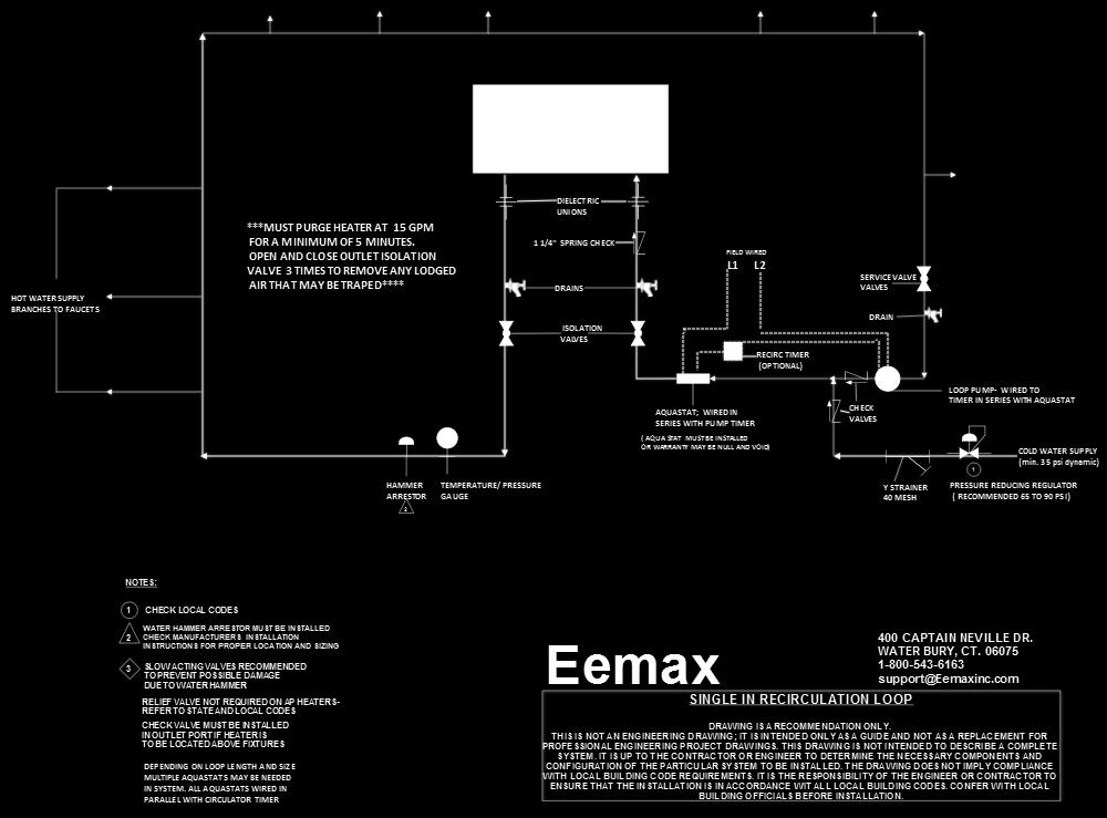
32 25 SINGLE IN RECIRCULATION LOOP

33 26 RECIRCULATION LOOP THROUGH HEATER OPTION 1

34 27 SINGLE WATER HEATER

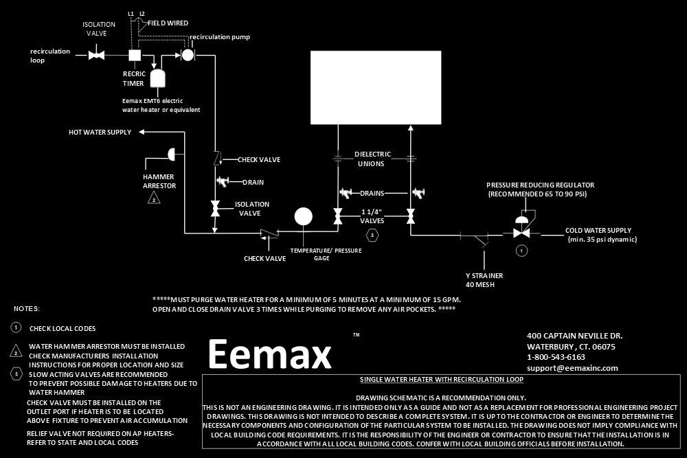
35 28 SINGLE HEATER WITH TANK

36 29 SINGLE HEATER WITH TANK WITH RECIRCULATION LOOP
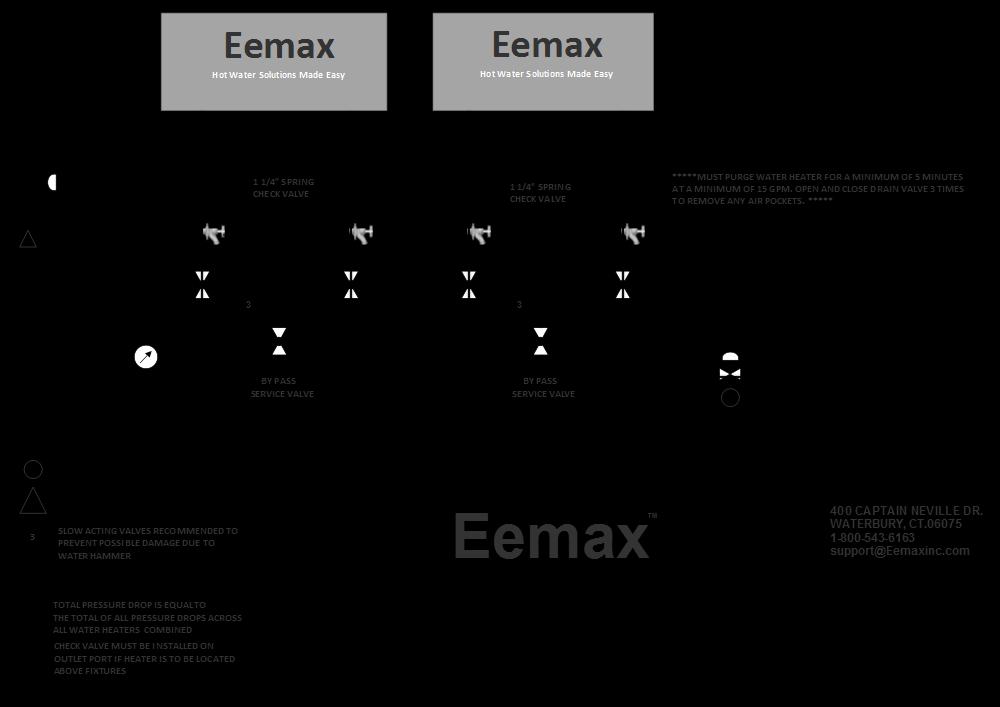
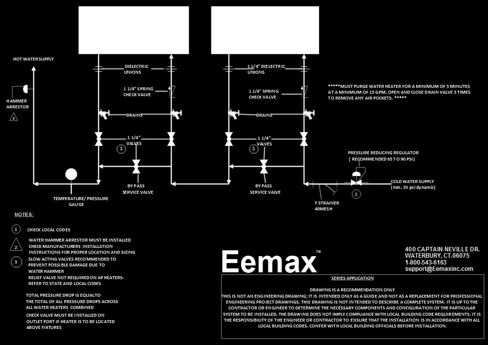
37 30 SERIES APPLICATION

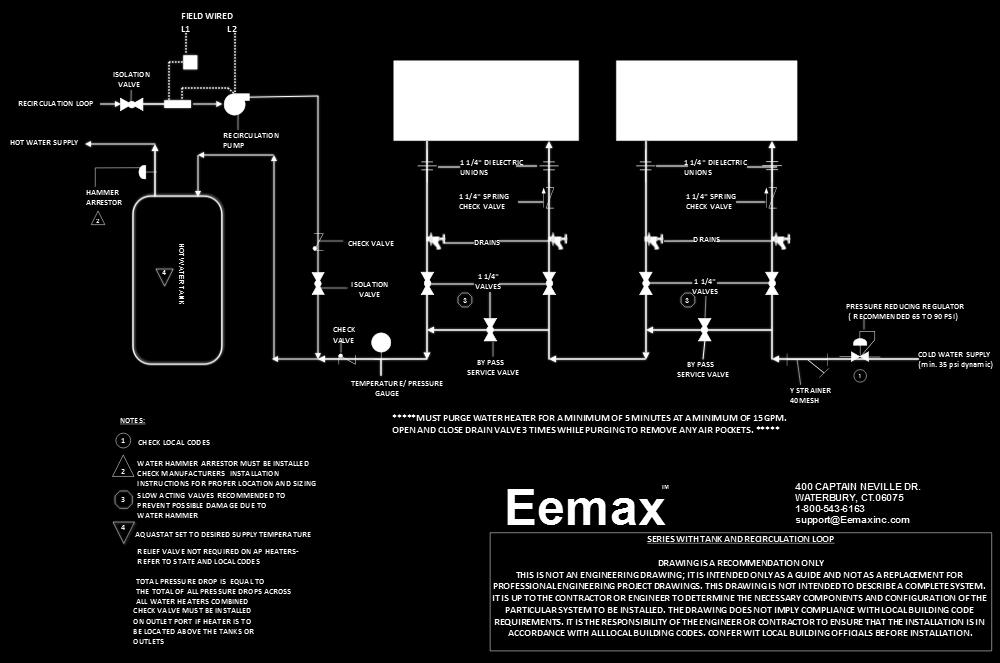
38 31 SERIES WITH TANK AND RECIRCULATION LOOP

39 32 SERIES APPLICATION WITH RECIRCULATION LOOP

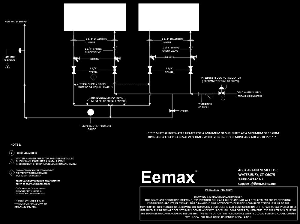
40 33 PARALLEL APPLICATION

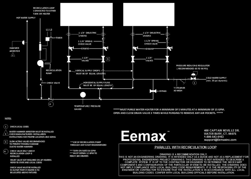
41 34 PARALLEL WITH RECIRCULATION LOOP

42 35 PARALLEL WITH TANK HEATER

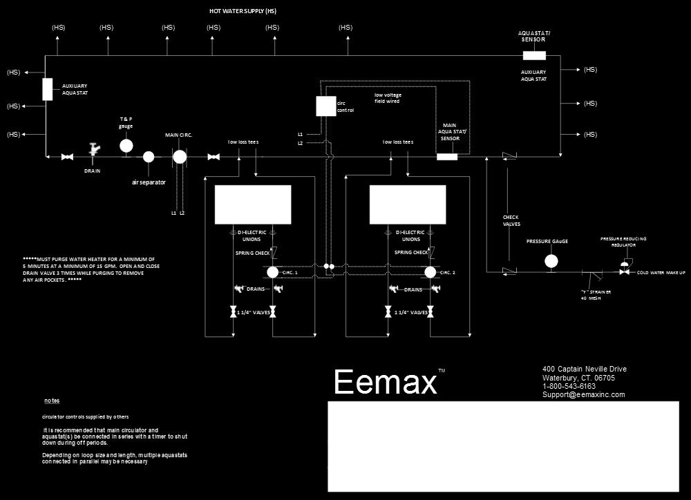
43 36 PARALLEL HEATERS WITH CIRCULATORS WITH STORAGE TANKS

44 37 PARALLEL HEATER WITH CIRCULATORS WITH DIP TUBE STORAGE TANK

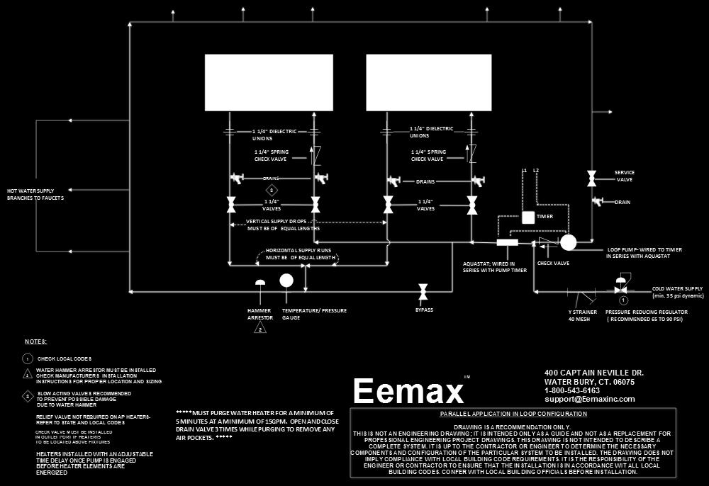
45 38 PARALLEL APPLICATION IN LOOP CONFIGURATION

46 39 PRIMARY/SECONDARY PIPING INSTALLATION

47 40 MULTIPLE HEATERS IN PRIMARY/SECONDARY PIPING INSTALLATION

48 41 RECIRCULATION LOOP WITH LOW LOSS HEADER TEES


49 42 STORAGE TANKS WITH HIGH FLOW DEMAND CIRCULATORS/LOW FLOW DEMAND HEATER


50 43 HOT WATER WITH SPACE HEATING


51 44 HOT WATER / SPACE HEATING

52 REPAIRS AND OPTIONS Repair Parts WARNING Service and repairs are to be performed by licensed electricians or qualified servicemen. WARNING Before attempting any repairs to the heater, make sure that the electrical breaker is off and confirm that there is no voltage at the heater. ECO s Electrical Connections Transformer LED Display Board Optical Sensor Boards Control Board Fuses Heating Element Assembly* Flow Meter ** SSR s * HEATING ELEMENT ASSEMBLY CONSISTS OF ONE HEATER CORE AND WIRE ELEMENT(S) ** FLOW METER KIT CONSISTS OF PADDLE WHEEL, DOWEL PIN, O RING AND 4 MOUNTING SCREWS. 45
53 Repair Parts (continued) V 480 Model Number Model Number Suffix Element Number Assembly Flow Meter Assembly (inc board) Triacs Assembly replaced by SSR Master Display Board Transformer Fuses SSR Assemble (incl. 3) ECO Assembly Optical Board Assembly AP EX B02 EX EX EX EX198 EX EX278A-Kit EX AP EE EX A04 EX EX EX EX198 EX EX278E-Kit EX AP S EX B00 EX EX EX EX198 EX EX278D-Kit EX AP EX B02 EX EX EX EX EX EX278A-Kit EX AP EE EX A04 EX EX EX EX EX EX278E-Kit EX AP S EX B00 EX EX EX EX EX EX278D-Kit EX AP EX B02 EX EX EX EX EX EX278A-Kit EX AP EFD EX A04 EX EX EX EX EX EX278E-Kit EX AP S EX B00 EX EX EX EX EX EX278D-Kit EX AP EX B02 EX EX EX EX198 EX EX278A-Kit EX AP EFD EX A04 EX EX EX EX198 EX EX278E-Kit EX AP S EX B00 EX EX EX EX198 EX EX278D-Kit EX AP EX B04 EX EX EX EX EX EX278A-Kit EX AP EFD EX A04 EX EX EX EX EX EX278E-Kit EX AP S EX B00 EX EX EX EX EX EX278D-Kit EX AP EX B02 EX EX EX N/A EX EX278A-Kit EX AP EE EX A04 EX EX EX N/A EX EX278E-Kit EX AP S EX B00 EX EX EX N/A EX EX278D-Kit EX AP EX B02 EX EX EX N/A EX EX278A-Kit EX AP EE EX A04 EX EX EX N/A EX EX278E-Kit EX AP S EX B00 EX EX EX N/A EX EX278D-Kit EX AP EX B02 EX EX EX N/A EX EX278A-Kit EX AP EFD EX A04 EX EX EX N/A EX EX278E-Kit EX AP S EX B00 EX EX EX N/A EX EX278D-Kit EX AP EX B04 EX EX EX EX EX EX278A-Kit EX
54 AP EFD EX A04 EX EX EX EX EX EX278E-Kit EX AP S EX B00 EX EX EX EX EX EX278D-Kit EX AP EX B04 EX EX EX EX198 EX EX278A-Kit EX AP EFD EX A04 EX EX EX EX198 EX EX278E-Kit EX AP S EX B00 EX EX EX EX198 EX EX278D-Kit EX AP EX B04 EX EX EX EX198 EX EX278A-Kit EX AP EFD EX A04 EX EX EX EX198 EX EX278E-Kit EX AP S EX B00 EX EX EX EX198 EX EX278D-Kit EX AP EX B04 EX EX EX EX198 EX EX278A-Kit EX AP EFD EX A04 EX EX EX EX198 EX EX278E-Kit EX AP S EX B00 EX EX EX EX198 EX EX278D-Kit EX AP EX B04 EX EX EX EX198 EX EX278A-Kit EX AP EFD EX A04 EX EX EX EX198 EX EX278E-Kit EX AP S EX B00 EX EX EX EX198 EX EX278D-Kit EX AP EX B04 EX EX EX EX EX EX278A-Kit EX AP EFD EX A04 EX EX EX EX EX EX278E-Kit EX AP S EX B00 EX EX EX EX EX EX278D-Kit EX AP EX B04 EX EX EX EX EX EX278A-Kit EX AP EFD EX A04 EX EX EX EX EX EX278E-Kit EX AP S EX B00 EX EX EX EX EX EX278D-Kit EX AP EX B04 EX EX EX EX EX EX278A-Kit EX AP EFD EX A04 EX EX EX EX EX EX278E-Kit EX AP S EX B00 EX EX EX EX EX EX278D-Kit EX AP EX B04 EX EX EX EX EX EX278A-Kit EX AP EFD EX A04 EX EX EX EX EX EX278E-Kit EX AP S EX B00 EX EX EX EX EX EX278D-Kit EX
, all piping and tubing must be fully reamed. Precautions must be taken to prevent crimping and other damage to protective gas piping and tubing.")
55 Options Optional Class 1 Division 2 Establishing Connections Sizes, Lengths & Bends Typical Single Protected Enclosure Connections Helpful Hints To ensure adequate protective gas flow to the protected enclosure(s), all piping and tubing must be fully reamed. Precautions must be taken to prevent crimping and other damage to protective gas piping and tubing. When protecting multiple enclosures with a single enclosure protection system, the enclosures must be connected in series from the smallest to the largest to ensure adequate protective gas flow. Determining Enclosure Inlet & Outlet Connection Locations Helpful Hints If flammable gases are lighter than air, the inlet connection to each enclosure must enter near a bottom corner. The outlet connection, for the required enclosure protection vent or piping to an adjacent protected enclosure, must exit near an extreme opposite top corner. If flammable gases are heavier than air, inlet and outlet connections must be reversed. In all cases, the most prevalent gas must determine the location of inlet and outlet connections. 48
 49")
56 NEMA Cabinet 4, 4X, 4X (316) 49

57 General Wiring Requirements WARNING THIS DEVICE CONTAINS ELECTRICAL PARTS WHICH CAN CAUSE SHOCK OR INJURY. All electrical connections, conduit and fittings on the protected enclosure must be suitable for the hazardous location in which they are installed. In addition, all conduit and wire must be installed in accordance with NEC as required and all relevant plant and local codes. Note: Do not use seals on conduit used as a protected "wireway" to supply protective gas to adjacent protected enclosures. The same conduit can be utilized for both electrical and pneumatic service to an adjacent protected enclosure(s), provided the conduit is oversized to allow a minimum free clearance equal to or larger than the pipe size required between multiple enclosures. Enclosure Power Requirements The protected enclosure(s) electrical power source must originate from a circuit breaker or fused disconnect suitable for the hazardous location in which it is installed. The switch must be located within fifty (50) (15.2 m) feet of the protected enclosure(s) and the protection system and be properly marked. Alarm Signal Requirements The WPSA style pressure switch requires a 120 VAC power supply in addition to the alarm signal. The WPS and WPSA Style system alarm signal may originate from the protected enclosure if the alarm signal is disconnected by the protected enclosure's circuit breaker or fused disconnect as stated in Enclosure Power Requirements above. The protected enclosure(s) alarm signal power may also originate from outside of the protected enclosure. In this application, the protected enclosure may be used as a "wireway" to pass alarm signal wiring from the power source to the alarm device, if the wiring is isolated and properly labeled. In addition, appropriate conduit seals must be provided outside of the protected enclosure separately. Important Note NFPA 496 requires the use of an alarm or an indicator to detect the loss of safe enclosure pressure. In addition, the NFPA 496 requires that if an indicator alone is utilized, a protective gas supply alarm must also be installed between the last valve in the protective gas supply and the protected enclosure. Therefore, the protective gas supply to all LPS Style systems must be equipped with the above mentioned protective gas supply alarm. Exception: Systems utilizing an EPSK or GPSK enclosure pressure loss alarm switch accessory will satisfy the above mentioned NFPA requirement. Electrical Supply Requirements Typical Enclosure Wiring Methods In a general sense, protected enclosures should be wired similar to explosion proof enclosures, in accordance with Article 500 of the National Electric Code - NFPA 70. Single conductor wiring should be placed in rigid metal conduit, seal-flex conduit or other mediums approved for use in the hazardous location surrounding the protected enclosure. Additionally, NFPA 496 requires the use of approved seals on all pressurized enclosure conduit wiring entries, in accordance with NFPA 70. Furthermore, the use of an approved seal is simply the most practical way to prevent excessive leakage through conduit connections. However, while explosion proof enclosures require conduit seals on all cable entries, in accordance with NFPA 70, other methods of sealed cable entries that are suitable for hazardous locations can be used, such as compression glands. In conclusion, there are two primary goals. First, the installer should ensure that all associated wiring and cable is protected by pressurization or other means, such as explosion proof conduit or intrinsic safety barriers. Secondly, the installer should ensure that all associated conduit and wireways are sealed to conserve protective gas, unless they are used to supply protective gas to other enclosures or devices. Typical Enclosure Wiring Connections 50

58 Electrical Conduit 1. Choose the location for the enclosure's electrical conduit connection(s) based on the requirements on page 49, "Electrical Supply Requirements". 2. Drill and deburr enclosure conduit fitting holes in the protected enclosure. Mount the fittings. 3. Determine appropriate route for the enclosure electrical and power alarm signal conduit 4. Measure, cut and thread conduit, check conduit fit to ensure proper seating. Fully ream all conduit. 5. Install conduit and tighten all fittings to fitting manufacturer s specifications. Secure conduit to appropriate structural supports as required. 6. Seal all conduit with an approved compound prior to operation of the protection system. Helpful Hint It may be impractical to pour all electrical conduit seals prior to installation in the field. However, all conduit connections must be sealed for proper testing and operation of the Enclosure Protection System. Therefore, the use of temporary seals such as duct seal or masking tape for bench or shop testing, prior to final field installation may be used. Conduit Installation WPS Style Conduit Connection Parts WPS & WPSA style systems provide electrical contacts for audible or visual alarm devices that signal a loss of protected enclosure pressure. They are calibrated to alarm at 0.15 (3.8 mm) for Class I applications. The switches are suitable for hazardous (classified) outdoor locations. Wiring must be installed with a seal and conduit: fittings suitable for the area. Alarm circuit power may be derived from the protected enclosure power source or an intrinsically safe alarm signal source. All associated alarm devices must be protected by suitable means (explosion proof, purged or intrinsically safe). WPS Style Conduit Connection Parts Fitting Kits Can Be Bebco Furnished 1. For EXP pressure loss alarm switch connected to an enclosure mounted alarm, one (1) LCK (L fitting Conduit Kit) or equivalent conduit elbow, coupling and seal fittings. 2. For EXP pressure loss alarm switch connected to a remote mounted alarm, one (1) TCK (T fitting Conduit Kit) or equivalent conduit tee, coupling and seal fittings. 3. One (1) lot 150# rating 1/2" galvanized or aluminum pipe. 51
59 Safe" pressure, for purposes of this manual, is defined as a minimum.25 inch (6.4 mm) of water column. Regulator may be in the locked position upon arrival. To adjust regulator, pull handle to outward position. Carefully insert T-bar valve key to align valve stem tip of both valves. Practice locking and unlocking key in the RECV valve stem. Practice and familiarization of this process should ease operation of the system. Set-up Procedure Helpful Hints To test the vent's operation, gently prod the vent flapper open with a soft pointed object, (example: eraser end of a pencil) ensuring that the vent valve works freely. On vertically configured vents, this can be accomplished from within the protected enclosure. Side mounted -90 configured vents can be tested by removing the conduit plug at the bottom of the mounting tee. Multiple operations require only one test per day if enclosure is not opened or left unattended. Important Notes The Rapid Exchange Control Valve and the Enclosure Pressure Control Valve are both operated by utilizing the removable T-bar Valve Key supplied with the system. The purge system is shipped with the T-bar Valve Key locked in the Rapid Exchange Control Valve stem. To remove the T- bar Valve Key, wrap your index and middle finger around the T-Bar and place your thumb firmly against the system face plate. Pull the T-bar Valve Key straight out firmly. This will unlock and free the T-bar Valve Key for use in the Enclosure Pressure Control Valve stem. When Set-Up or Operating procedures are complete. Replace the T-bar Valve Key in the Rapid Exchange Control Valve stem and push in firmly to lock in position. THE T-BAR VALVE KEY LOCKS IN THE RAPID EXCHANGE CONTROL VALVE STEM ONLY. Operators must secure wrist or stop watch to manually time Exchange Cycle for all applications. Pepperl+Fuchs Rapid Exchange Purging Systems are designed to provide a pre-calibrated and certified volume exchange rate. With the Rapid Exchange pressure gauge set at 60 psi (4.14 bar) minimum, the model 3003 will accomplish the required volume exchanges at a rate of ONE MINUTE PER 3 CUBIC FOOT (85 /min) of enclosure volume. The volume exchange rate is based on a four (4) enclosure volume exchange. Multiply the required exchange time by 2.5 for applications requiring a ten (10) volume exchange for motors. Regardless of enclosure volume or system flow rate. Pepperl+Fuchs requires that operators withhold power to the enclosure while inducing the Class I enclosure volume exchange, for at least five (5) minutes. Normal exchange times should be doubled if large obstructions block protective gas flow. Class I Purging Set-Up READ IMPORTANT NOTES BEFORE PROCEEDING WITH SET-UP 1. Utilizing the T-bar Valve Key supplied with system (see important notes), close Rapid Exchange Control and Enclosure Pressure Valves fully by turning clockwise (CW). 2. Engage the protective gas supply to the System Supply Inlet and set the Rapid Exchanger Pressure Gauge to 60 psi. 3. Temporarily connect a 0-10 inch (0-254 mm) water column pressure gauge or manometer to the protected enclosure. 4. Check operation of Enclosure Protection Vent as detailed above. (see Helpful Hints ) 5. Seal enclosure(s) and adjust Enclosure Pressure Control Valve, utilizing the T-bar Valve Key, by opening slowly counterclockwise (CCW) to set a "Safe" pressure on the Enclosure Pressure Gauge. NOTE: If pressure setting is difficult to stabilize or set. (see page 18, "Trouble-Shooting Procedures"). 6. Carefully remove T-bar Valve Key from Enclosure Pressure Control Valve stem. Ensure Enclosure Pressure Gauge "Safe" pressure setting is stable. 7. Utilizing the T-bar Valve Key supplied with system (see important notes above), lock T-bar Valve Key into Rapid Exchange Control Valve stem. Open valve fully by turning 90 CCW and quickly ensure the Enclosure Protection Vent opens. Note: The Enclosure Pressure Gauge should move quickly off scale to the right, this is normal for all Rapid Exchange purging systems. 8. Readjust the regulator to 60 psi (4.14 bar) minimum, while inducing Rapid Exchange until the test gauge reads approximately 3 to 5 inches ( mm) of pressure and does not fluctuate. (insufficient enclosure pressure will cause the Enclosure Protection Vent to "shuttle') DO NOT exceed 10 inches (254 mm) of pressure within the protected enclosure. 9. Close Rapid Exchanger Control Valve fully and ensure T-bar Valve Key is firmly locked in Rapid Exchange Control Valve stem. 10. Cease testing and remove test equipment. 52

60 Operating Sequence WARNING Do not exceed Safe pressure with the Enclosure Pressure Control Valve. Operators must follow step-by-step sequence of the Start-Up Instructions Nameplate on the Protection System. Class I Purging Operation With the protective gas supply connected, enclosure power deenergized and alarm system energized (if utilized). 1. Carefully read Start-Up Instructions on system. 2. Check operation of the Enclosure Protection Vent (EPV-3) opening it manually several times. (see page 50, 'Helpful Hint"). 3. Seal protected enclosure(s). 4. Unlock T-bar Valve Key from the RECV stern and place in the EPCV stern. (see important notes, page 50), open Enclosure Pressure Control Valve, by turning CCW. to set Enclosure Pressure Gauge at Safe pressure, the Pressure Loss Alarm Switch (if utilized) should then activate to silence the alarm system. 5. Ensure the Protection System Enclosure Pressure Gauge maintains a "Safe" pressure for one (1) minute. 6. Carefully remove T-bar Valve Key from Enclosure Pressure Control Valve stem. Ensure Enclosure Pressure Gauge Safe pressure setting is stable. 7. Utilizing the T-Par Valve Key supplied with system, open Rapid Exchange Control Valve fully by turning 90 CCW and quickly ensure the Enclosure Protection Vent opens. Note: The Enclosure Pressure Gauge should move quickly off scale to the right, this is normal for all Rapid Exchange purging systems. 8. Standby for the exchange time as specified on the Start-Up Instructions (five minutes minimum) then close the Rapid Exchange Control Valve fully and ensure T-bar Valve Key is firmly locked in Rapid Exchange Control Valve stem. 9. Wait for the Enclosure Pressure Gauge to return to a Safe pressure and energize the protected enclosure(s) power via the local disconnect switch. 10. Ensure the Enclosure Pressure Indicator maintains a "Safe" pressure before leaving system unattended. 53

61 54 STD WITH EP OPTION (INERT GAS SUPPLIED BY CUSTOMER)
62 55 AVAILABLE WITH EP-6000 UNIT
63 System Maintenance Regular Maintenance Drain the Protection System Filter (if utilized) frequently and clean system with non-solvent cleaning agents only. Long Term Maintenance Calibrate the enclosure pressure indicator to 0 inches by venting the purge pressure reference port and the protected enclosure to atmosphere and adjusting the calibration screw in the lower center portion of the indicator s face. Fully open the enclosure pressure control valve, to blow out any deposits around the tip of the valve and to ensure that the enclosure protection vent is operating properly, then carefully readjust system according to the set-up procedure and operating sequence on pages 50. Replace or tighten stem packing nut as required to prohibit stem packing leakage. Carefully disassemble the enclosure protection vent by loosening the two bottom hex nuts that hold the unit together. (DO NOT REMOVE CAP NUTS ON TOP OF VENT BODY) Carefully clean the flapper valve and vent body seats with warm soap and water, being careful not to extend the vent valve beyond its normal opening point, and being careful not to exert any stress on the valve hinge. Examine the entire Protection System and the protected enclosure(s), and replace any defective parts curing routine shutdown of the protected enclosure(s). Parts are available from Pepperl+Fuchs on immediate notice as required. Maintenance Schedule Date Work Performed Performed By 56

 Set the thermostat on the enclosure heater, located at the upper left corner in the enclosure, to 40 70 degrees F. Note: Heater fan continuously operates to recirculate air in the enclosure.")
64 Optional Enclosure Heater 1) Attach heat tape and foam insulation to all lengths of inlet and outlet water piping that are exposed to freezing temperature. We recommend a rating of -30 degrees F at 10 miles per hour wind. Connect the heat tape to an independent source of electrical power. CAUTION Failure to attached heat tape and insulation to exposed inlet and outlet pipes will void the warranty. 2) Set the thermostat on the enclosure heater, located at the upper left corner in the enclosure, to degrees F. Note: Heater fan continuously operates to recirculate air in the enclosure. The heater coil will activate based on thermostat set point. Note: Power must be applied to the water heater for the freeze protection system to operate. If power is not applied ensure the system is completely drained. Neglecting to do so will damage the heater and void the warranty. 57


65 Optional GFCI The optional GFCI consist of (A) Control Module and (B) Current Transformer. This control module has a LCD display indicating real-time measurements. The GFCI module is preset from factory to trip at 3.0 A. Test and reset functions are carried out automatically every 24 hours. To manual test the GFCI, press the test button for a minimum of 1.5 seconds. To reset a tripped GFCI, cycle the power of the unit. If equipped with a disconnect handle, turn the handle to the OFF position then back to ON. 58
66 Optional NON-FUSIBLE Disconnect Switch DISCONNECT SWITCH MODEL 60 A 100 A 200 A Operating Voltage 600 V 600 V 600 V Max Horsepower Rating: 120 VAC 1-Phase /240 VAC 1-Phase /240 VAC 3-Phase /480 VAC 3-Phase VAC 3=Phase Short circuit rating with fuses Branch circuit fuse type J J J Max fuse rating (A) Disconnect Handle NEMA Type: 4, 4X Color: Red/Yellow 59
67 Optional FUSIBLE Disconnect Switch DISCONNECT SWITCH MODEL 200 AMP 100 AMP RATING (A) 200 A 100 A Max horsepower rating/ Max motor FLA current phase Three 600 V 600 V 208 v 50/150 25/ v 60/154 30/ v 125/156 60/ v 130/144 75/77 DC 125 V (2 pole in series) 15/ /58 DC 250 V (3 pole in series) 40/140 20/38 Short circuit rating with fuses Branch circuit fuse type J J Max fuse rating (A) DISCONNECT HANDLE NEMA TYPE: 4,4x COLOR: RED/YELLOW 60


68 WIRING SCHEMATICS 120V COM 480V L1 120V 480V L2 RELAY COIL A1 COIL A2 AP SIREN BEACON ONLY WIRING DIAGRAM 61

69 120V COM 120V RELAY COIL A1 TOP CONTACTOR COIL A2 AP SIREN BEACON ONLY WIRING DIAGRAM 62

70 CONTACTOR COILS A2 A1 L1 CT RING GFCI SIREN BEACON DIAG L2 L3 X1 X2 XFR 2 SIREN/ BEACON X1 X2 PHD XFR H1 120V H2 120V COM H1 24VAC H2 24VAC RTN GFCI FUSE SB FUSE AUX CONTACT 1 NC COM PHD MCB C1 NO C2 C3 P17 P16 ECO ECO ECO ECO ECO ECO


71 (H2) 120V COM (H1) 120V X1 208/480/600 L1 X2 208/480/600 L2 TO COM TO NO ATTACHES TO SIDE OF CONTACTOR COIL A1 TOP CONTACTOR COIL A2 AP SIREN BEACON ONLY WIRING DIAGRAM 64
INSTALLATION INSTRUCTIONS AND OWNER S MANUAL FOR
 INSTALLATION INSTRUCTIONS AND OWNER S MANUAL FOR ELECTRIC ON-DEMAND TANKLESS WATER HEATERS: SpecAdvantage with PhD Technology SafeAdvantage with PhD Technology 208 and 480 VAC three phase 32 144 kw 600
INSTALLATION INSTRUCTIONS AND OWNER S MANUAL
 INSTALLATION INSTRUCTIONS AND OWNER S MANUAL ELECTRIC INSTANTANEOUS WATER HEATERS WITH PhD 208 and 480 VAC three phase 32 144 kw 600 VAC three phase 130 / 150 kw BEFORE ATTEMPTING ANY INSTALLATION OR SERVICE
INSTALLATION, OPERATION, AND MAINTENANCE MANUAL FOR ELECTRIC TANKLESS WATER HEATERS
 INSTALLATION, OPERATION, AND MAINTENANCE MANUAL FOR ELECTRIC TANKLESS WATER HEATERS MODELS 9326 & 9327 0002080089, Rev 2 IMPORTANT SAFETY INFORMATION READ ALL INSTRUCTIONS BEFORE USING DANGER Indicates
PRO SERIES IMPORTANT SAFETY INFORMATION
 INSTALLATION INSTRUCTIONS & HOME OWNERS MANUAL PRO SERIES IMPORTANT SAFETY INFORMATION When installing or using any high voltage electrical appliance, basic safety precautions should always be followed.
HOMEADVANTAGE II IMPORTANT SAFETY INFORMATION
 INSTALLATION INSTRUCTIONS & HOME OWNERS MANUAL HOMEADVANTAGE II HA008240 HA011240 HA013240 HA018240 HA024240 HA027240 HA036240 IMPORTANT SAFETY INFORMATION When installing or using any high voltage electrical
INSTALLATION INSTRUCTIONS & HOME OWNERS MANUAL ECO 18 ECO 24 ECO 27 IMPORTANT SAFETY INFORMATION
 INSTALLATION INSTRUCTIONS & HOME OWNERS MANUAL ECO 18 ECO 24 ECO 27 IMPORTANT SAFETY INFORMATION As when installing or using any high voltage electrical appliance, basic safety precautions should always
INSTALLATION GUIDE AND OWNER S MANUAL. AccuMix II ELECTRIC INSTANTANEOUS WATER HEATER WITH ASSE 1070 APPROVED MIXING VALVE
 INSTALLATION GUIDE AND OWNER S MANUAL AccuMix II ELECTRIC INSTANTANEOUS WATER HEATER WITH ASSE 1070 APPROVED MIXING VALVE 2 BEFORE ATTEMPTING ANY INSTALLATION, MODIFICATION OR SERVICE OF THIS HEATER, MAKE
INSTALLATION GUIDE AND OWNER S MANUAL
 INSTALLATION GUIDE AND OWNER S MANUAL SINGLE POINT, FLOW CONTROLLED and THERMOSTATIC ELECTRIC INSTANTANEOUS WATER HEATERS BEFORE ATTEMPTING ANY INSTALLATION, MODIFICATION OR SERVICE OF THIS HEATER, MAKE
EEMAX ProAdvantage Series 1
 EEMAX ProAdvantage Series 1 ELECTRIC INSTANTANEOUS WATER HEATER INSTALLATION GUIDE AND OWNER S MANUAL MODELS COVERED: PA004120T 1Φ 120V PA008208T 1Φ 208V PA005240T 1Φ 240V PA007240T 1Φ 240V PA010240T 1Φ
INSTALLATION, OPERATION, AND MAINTENANCE MANUAL FOR THE HUBBELL MODEL TX / HX TANKLESS WATER HEATER
 INSTALLATION, OPERATION, AND MAINTENANCE MANUAL FOR THE HUBBELL MODEL TX / HX TANKLESS WATER HEATER ELECTRIC HEATER COMPANY Edition 2012A HUBBELL ELECTRIC HEATER COMPANY P.O. BOX 288 STRATFORD, CT 06615-0288
Use & Care Manual. Electric Tankless Water Heaters. With Installation Instructions for the Installer AP15447 (10/10)
") Use & Care Manual With Installation Instructions for the Installer Electric Tankless Water Heaters The purpose of this manual is twofold: one, to provide the installer with the basic directions and recommendations
Use & Care Manual With Installation Instructions for the Installer Electric Tankless Water Heaters The purpose of this manual is twofold: one, to provide the installer with the basic directions and recommendations
EEMAX SERIES-TWO WATER HEATERS
 EEMAX SERIES-TWO WATER HEATERS ELECTRIC INSTANTANEOUS WATER HEATER INSTALLATION GUIDE AND OWNERS MANUAL MODELS COVERED:- EX190 TC, T2-240/208 V EX144 TC, T2-240/208 V EX1608 TC, T2 208V EX160 TC, T2-277
EEMAX HOME ADVANTAGE
 EEMAX HOME ADVANTAGE ELECTRIC INSTANTANEOUS WATER HEATER INSTALLATION GUIDE AND OWNERS MANUAL MODELS COVERED:- SS015240TC 208-240V SS019240TC 208-240V READ THE GENERAL SAFETY SECTION BEGINNING ON THE INSIDE
SuperStor Ultra Stainless Steel Storage Tank
 SuperStor Ultra Stainless Steel Storage Tank INSTALLATION START-UP MAINTENANCE PARTS Storage Tank Models SSU-30CB / SSU-45CB SSU-60CB / SSU-80CB / SSU-119CB For Residential and Commercial Use This manual
INSTALLATION, OPERATION, AND MAINTENANCE MANUAL FOR THE HUBBELL TANKLESS WATER HEATER
 INSTALLATION, OPERATION, AND MAINTENANCE MANUAL FOR THE HUBBELL TANKLESS WATER HEATER ELECTRIC HEATER COMPANY Edition 2016A HUBBELL ELECTRIC HEATER COMPANY P.O. BOX 288 STRATFORD, CT 06615-0288 PHONE:
INSTALLATION INSTRUCTIONS & HOME OWNERS MANUAL AUTOBOOSTER IMPORTANT SAFETY INFORMATION
 INSTALLATION INSTRUCTIONS & HOME OWNERS MANUAL AUTOBOOSTER IMPORTANT SAFETY INFORMATION When installing or using any high voltage electrical appliance, basic safety precautions should always be followed.
SEISCO SUPERCHARGER EXTENDER/BOOSTER INSTALLATION GUIDE & OWNERS MANUAL
 SEISCO SUPERCHARGER EXTENDER/BOOSTER INSTALLATION GUIDE & OWNERS MANUAL This manual is provided as a guide to installation. All installations must comply with any and all local and national electrical
OPERATION & INSTALLATION MANUAL IR-30, IR-234, IR-245, IR-260, IR-288, IR-14K220, IR-18K220. Electric Tankless Hot Water Heater
 OPERATION & INSTALLATION MANUAL IR-30, IR-234, IR-245, IR-260, IR-288, IR-14K220, IR-18K220 Electric Tankless Hot Water Heater Table of Contents SAFETY INFORMATION... 1 INTRODUCTION... 2 Unit Operation...
SNA-SKID Series - Preassembled Safety Shower Heater Skid Tankless Water Heating Solutions
 Pre-assembled skid system Back-to-Back heater models, SNA & SNAR High Flow Demand Safety Shower Applications 216-288 kw (737,000-983,000 BTUs) Temperature overshoot purge system NEMA 4 enclosure standard
INSTALLATION, OPERATION, AND MAINTENANCE MANUAL FOR THE HUBBELL MODEL JTX TANKLESS BOOSTER HEATER ELECTRIC HEATER COMPANY
 INSTALLATION, OPERATION, AND MAINTENANCE MANUAL FOR THE HUBBELL MODEL JTX TANKLESS BOOSTER HEATER ELECTRIC HEATER COMPANY Edition 2011 HUBBELL ELECTRIC HEATER COMPANY P.O. BOX 288 STRATFORD, CT 06615-0288
INSTALLATION, OPERATING & MAINTENANCE INSTRUCTIONS FOR 350 SERIES CIRCULATION HEATERS
 INDEECO Circulation Heaters are designed to provide years of trouble free operation if properly installed and maintained. Please read and follow these instructions for installing and maintaining the heater.
Keltech SNA-Series - Safety Shower Heaters Tankless Water Heating Solutions
 36-144 kw (122,800-491,300 BTUs) Temperature overshoot purge system Certified Lead-Free Design NEMA 4 enclosure standard ASME and NB Certified options available New & Improved Pressure Drop Advantage Dual
WAIWELA SERIES-TWO WATER HEATERS
 WAIWELA SERIES-TWO WATER HEATERS ELECTRIC INSTANTANEOUS WATER HEATER INSTALLATION GUIDE AND OWNERS MANUAL MODELS COVERED WET-12 T, TC, T2-240/208 V SPECIAL, V READ THE GENERAL SAFETY SECTION BEGINNING
TRONIC 6000C. Tankless electric whole house water heaters. Models: WH17 / WH27. [en] Installation Manual and Operating Instructions
![TRONIC 6000C. Tankless electric whole house water heaters. Models: WH17 / WH27. [en] Installation Manual and Operating Instructions](/thumbs/84/89125790.jpg "TRONIC 6000C. Tankless electric whole house water heaters. Models: WH17 / WH27. [en] Installation Manual and Operating Instructions") Tankless electric whole house water heaters TRONIC 6000C Models: WH17 / WH27 [en] Installation Manual and Operating Instructions 6 720 646 951 (2017/05) US 2 Table of contents Table of contents 1 Explanation
Tankless electric whole house water heaters TRONIC 6000C Models: WH17 / WH27 [en] Installation Manual and Operating Instructions 6 720 646 951 (2017/05) US 2 Table of contents Table of contents 1 Explanation
EEMAX PROADVANTAGE ELECTRIC INSTANTANEOUS WATER HEATER INSTALLATION GUIDE AND OWNERS MANUAL
 EEMAX PROADVANTAGE ELECTRIC INSTANTANEOUS WATER HEATER INSTALLATI GUIDE AND OWNERS MANUAL MODELS COVERED Triple Module Models PA018208T2T, PA024208T2T, PA018277T2T, PA024277T2T, PA032277T2T Single Phase
Discontinued. SN Series - Safety Shower Heaters Tankless Water Heating Solutions. Standard Equipment. Construction. Code Compliance and Certifications
 36-144 kw (122,800-491,300 BTUs) Temperature overshoot purge system Certified Lead-Free Design NEMA 4 enclosure standard ASME and NB Certified options available Pressure Drop Advantage Dual Flow Activation
INSTALLATION, OPERATION, AND MAINTENANCE MANUAL FOR THE HUBBELL MODEL JTX / JHX TANKLESS BOOSTER HEATER
 INSTALLATION, OPERATION, AND MAINTENANCE MANUAL FOR THE HUBBELL MODEL JTX / JHX TANKLESS BOOSTER HEATER ELECTRIC HEATER COMPANY * The Hubbell Model JTX is designed for use with conveyor and flight type
INSTALLATION INSTRUCTIONS & HOME OWNERS MANUAL TANKBUDDY IMPORTANT SAFETY INFORMATION
 INSTALLATION INSTRUCTIONS & HOME OWNERS MANUAL TANKBUDDY IMPORTANT SAFETY INFORMATION When installing or using any high voltage electrical appliance, basic safety precautions should always be followed.
SERIES THREE 480 VOLT 3 PHASE DELTA ELECTRIC INSTANTANEOUS WATER HEATER
 SERIES THREE 480 VOLT 3 PHASE DELTA ELECTRIC INSTANTANEOUS WATER HEATER INSTALLATION AND OWNERS MANUAL BEFORE ATTEMPTING INSTALLATION OF THIS UNIT OR MAKING ANY ADJUSTMENTS TO THE UNIT ALWAYS BE SURE MAIN
SAVE THESE INSTRUCTIONS
 Important Safety Instructions When using this electrical equipment, basic safety precautions should always be followed, including the following: 1. READ AND FOLLOW ALL INSTRUCTIONS. 2. This appliance must
ECCOTEMP. Point of Use Tankless Water Heaters EP-2.4 / EP-7.0. Installation and Operating Instruction Manual. Shop Online.
 ECCOTEMP Point of Use Tankless Water Heaters EP-2.4 / EP-7.0 Installation and Operating Instruction Manual Product Support Eccotemp.com/help-desk Shop Online Eccotemp.com/products Store Locator Eccotemp.com/locator
SMARTBOOST IMPORTANT SAFETY INFORMATION
 INSTALLATION INSTRUCTIONS & HOME OWNERS MANUAL SMARTBOOST IMPORTANT SAFETY INFORMATION When installing or using any high voltage electrical appliance, basic safety precautions should always be followed.
Installation and Operation Guide
 Hot Water on Demand Installation and Operation Guide Thermostatic Series 18kW, 21kW, 24kW 118 º F www.atmorusa.com Table of Contents Description Page Safety Guidelines...2 Technical Information...3 Plumbing...
EEMAX THREE MODULE, SINGLE PHASE WATER HEATERS
 EEMAX THREE MODULE, SINGLE PHASE WATER HEATERS ELECTRIC INSTANTANEOUS WATER HEATER INSTALLATI GUIDE AND OWNERS MANUAL MODELS COVERED:- EX230T2T 208/240V EX280T2T 208/240 V SPECIAL, V READ THE GENERAL SAFETY
CNA-Series - Large Industrial Heaters Tankless Water Heating Solutions
 36-144 kw (122,800-491,300 BTUs) Certified Lead-Free Design New & Improved Pressure Drop Advantage Variable Temp Heat Exchanger NEMA 4 enclosure standard Independent Safeties ETL and cetl certified to
User s Information Manual
 User s Information Manual Gas-Fired Storage Water Heater, Tankless Water Heater, Heating Appliance, and Combination Appliance Models IF THE INFORMATION IN THIS MANUAL IS NOT FOLLOWED EXACTLY, A FIRE OR
SuperStor Glass Lined Storage Tank
 SuperStor Glass Lined Storage Tank INSTALLATION MAINTENANCE TROUBLESHOOTING PARTS Storage Tank Models GL-50 / GL-80* GL-119* / GL-175* For Residential and Commercial Use *Available in Metal Jacketed ASME
C1N Series - Light Industrial Heaters Tankless Water Heating Solutions
 18-25 kw (61,4000-85,300 BTUs) Low flow activation options at 0.25 and 0.50 GPM (1.0 and 1.9 LPM) Certified Lead-Free Design Variable Temp Heat Exchanger Pressure Drop Advantage NEMA 4 enclosure standard
OPERATING AND INSTALLATION MANUAL
 OPERATING AND INSTALLATION MANUAL TANKLESS ELECTRIC WATER HEATER WITH ELECTRO-MECHANICAL FLOW SWITCH» MINI 2» MINI 2.5» MINI 3» MINI 3.5» MINI 4» MINI 6 The Mini series is tested and certified by WQA against
OPERATION & INSTALLATION MANUAL
 OPERATION & INSTALLATION MANUAL Model: SIO 14 & SIO 18 Electric Tankless Hot Water Generators Table of Contents SAFETY INFORMATION... 1 INTRODUCTION... 2 Unit Operation:... 2 Unit Freezing:... 3 Maintenance:...
OWNER S MANUAL. Vintage Classic HEAT COOL models. Proudly Made in the USA
 OWNER S MANUAL Vintage Classic HEAT COOL models Proudly Made in the USA support@aquacomfort.com www.aquacomfort.com/service-and-support 888-475-7443 Manufacturing High Quality, High Efficiency Heat Pump
OPERATIONS MANUAL 5 LITER LPG GAS TANKLESS WATER HEATER C AMPER SERIES
 OPERATIONS MANUAL 5 LITER LPG GAS TANKLESS WATER HEATER C AMPER SERIES MODEL # AGL-5 DRAKKEN INDUSTRIES LLC 790 W. 20 th St. Suite-103, Hialeah, FL. 33010 Toll:1-888-818-4328 Table of Contents Use and
OPERATING AND INSTALLATION MANUAL
 OPERATING AND INSTALLATION MANUAL TANKLESS ELECTRIC WATER HEATER WITH ELECTRO-MECHANICAL FLOW SWITCH» MINI 2» MINI 2.5» MINI 3» MINI 3.5» MINI 4» MINI 6 The Mini series is tested and certified by WQA against
Chromalox. Installation, Operation. Screw Plug Heating Solution Control Panel Assembly for Screw Plug Heaters RENEWAL PARTS IDENTIFICATION
 Chromalox Installation, Operation and RENEWAL PARTS IDENTIFICATION DIVISION SALES REFERENCE DATE 4 (Supersedes PG422-) DECEMBER, 2000 SECTION RAD PE440 6-058074-002 Screw Plug Heating Solution Control
COMPASS HIGH-EFFICIENCY WET-ROTOR CIRCULATORS
 COMPASS HIGH-EFFICIENCY WET-ROTOR CIRCULATORS INSTALLATION AND OPERATING INSTRUCTIONS File No: 10.895 Date: march 8, 014 Supersedes: 10.895 Date: december 10, 013 1.0 Symbols used in this document 1.0
OPERATING AND MAINTENANCE MANUAL FOR ELECTRIC STAINLESS STEEL HEATER FOR DEIONIZED (DI) WATER ELECTRIC HEATER COMPANY BASE MODEL D
 WATER ELECTRIC HEATER COMPANY BASE MODEL D") OPERATING AND MAINTENANCE MANUAL FOR ELECTRIC STAINLESS STEEL HEATER FOR DEIONIZED (DI) WATER ELECTRIC HEATER COMPANY BASE MODEL D HUBBELL ELECTRIC HEATER COMPANY P.O. BOX 288 STRATFORD, CT 06615 PHONE:
OPERATING AND MAINTENANCE MANUAL FOR ELECTRIC STAINLESS STEEL HEATER FOR DEIONIZED (DI) WATER ELECTRIC HEATER COMPANY BASE MODEL D HUBBELL ELECTRIC HEATER COMPANY P.O. BOX 288 STRATFORD, CT 06615 PHONE:
THERMAPHASE INSTALLATION AND OPERATING INSTRUCTIONS
 Page 1 of 10 THERMAPHASE INSTALLATION AND OPERATING INSTRUCTIONS Purpose of Manual The purpose of this manual is to provide operating, servicing and repair instructions for the Summit standard models ThermaPhase
Installation and Operation Guide
 Hot Water on Demand Installation and Operation Guide Thermo Boost Instant Water Heater Digital electric tankless instant water heater provides endless supply of hot water while significantly conserving
DISHWASHER. Models DW2432 and DW2432SS. Installation Manual. Write Serial Number (on inner door of unit) here:
 here:") DISHWASHER Models DW2432 and DW2432SS Installation Manual Write Serial Number (on inner door of unit) here: Felix Storch, Inc. Summit Appliance Division 770 Garrison Avenue Bronx, New York 10474 www.summitappliance.com
DISHWASHER Models DW2432 and DW2432SS Installation Manual Write Serial Number (on inner door of unit) here: Felix Storch, Inc. Summit Appliance Division 770 Garrison Avenue Bronx, New York 10474 www.summitappliance.com
Heat Transfer Products, Inc. 120 Braley Road East Freetown, MA The first totally integrated multiple boiler management control.
 Heat Transfer Products, Inc. 120 Braley Road East Freetown, MA 02717 The first totally integrated multiple boiler management control. USING THIS MANUAL USING THIS MANUAL A. INSTALLATION SEQUENCE Follow
S19361F - Pre-Assembled Freeze-Protected Safety Shower Heater Skid Tankless Water Heating Safety Solutions
 Pre-assembled, freeze-protected safety fixture and SNA heater skid system Bradley Heat Trace S19-300 with SpinTec 54-144 kw (491,300 BTUs) Molded Duragrate and integrated shower pan Temperature overshoot
INSTALLATION & MAINTENANCE MANUAL FOR QuickDraw
 INSTALLATION & MAINTENANCE MANUAL FOR QuickDraw SEMI-INSTANTANEOUS ENERGY: STEAM TO WATER U-TUBE SINGLE-WALL & DOUBLE-WALL HEAT EXCHANGERS FLOOR DRAIN Typical Construction Figure 34-1 FLOOR DRAIN 1. U-tube
Installation & Operation Manual Models: TSU
 TSU-I-O Rev A Installation & Operation Manual Models: TSU 150-940 CAUTION: This appliance is not intended for potable water. This manual must only be used by a qualified heating installer / service technician.
Eemax, Inc. Electric Tankless Water Heaters
 Eemax, Inc. Electric Tankless Water Heaters INSTALLATION INSTRUCTIONS & OWNER S MANUAL HotMax HM013240 IMPORTANT SAFETY INFORMATION When installing or using any high voltage electrical appliance, basic
POWERSTAR PS19T / PS28T, SINGLE PHASE WATER HEATERS
 POWERSTAR PS19T / PS28T, SINGLE PHASE WATER HEATERS ELECTRIC INSTANTANEOUS WATER HEATER INSTALLATI GUIDE AND OWNERS MANUAL WARNING READ THE GENERAL SAFETY SECTI BEGINNING THE INSIDE COVER AND THEN THIS
Portable C2N Series - Light Industrial Heaters Tankless Water Heating Solutions
 Portable C2N Series - Light Industrial Heaters Heavy duty industrial cart options simplify moving heater to various locations 36-50 kw (122,800-170,600 BTUs) Variable Temp Heat Exchanger Pressure Drop
Tankless Water Heater
 Tankless Water Heater USER S INFORMATION MANUAL Models WGRT**150 / WGRT**199 / WGRTC**199 **A suffix of LP denotes propane gas **A suffix of NG denotes natural gas NOTICE: Westinghouse reserves the right
INSTALLATION, OPERATING & MAINTENANCE INSTRUCTIONS FOR 870 SERIES INDUSTRIAL CONTROL PANELS
 INSTALLATION, OPERATING & MAINTENANCE INSTRUCTIONS FOR 870 SERIES INDUSTRIAL CONTROL PANELS GENERAL INDEECO Industrial Control Panels are designed to provide years of trouble free operation if properly
MASTER JOCKEY PUMP CONTROLLER. Model JPCE INSTRUCTION MANUAL. C 2018 Master Control Systems, Inc
 MASTER JOCKEY PUMP CONTROLLER Model JPCE INSTRUCTION MANUAL C 2018 Master Control Systems, Inc TABLE OF CONTENTS Important Safety Information. Page 3 General Description and Installation.. Page 4 Model
Clean Water Made Easy. CWS Time Clock Softener Installation & Start Up Guide. Questions?
 Clean Water Made Easy www.cleanwaterstore.com CWS Time Clock Softener Installation & Start Up Guide Thank you for purchasing a Clean Water System! With proper installation and a little routine maintenance
Niles Steel Tank Hot Water Generator Installation and Operation Manual
 Niles Steel Tank Hot Water Generator Installation and Operation Manual Contents: Contents 1 Hazard definitions 1 1. General Information.... 2 Availability... 3 Optional Control Packages... 5 2. Installation....
Installation and Operation Guide
 Hot Water on Demand Installation and Operation Guide Thermo-Pro Thermostatic Series 18kW, 21kW, 24kW, 27kW 118 º F www.atmorusa.com Table of Contents Description Page Safety Guidelines...2 Technical Information...3
INSTRUCTION MANUAL INSTALLATION OPERATION MAINTENANCE
 I.O.M. #083 /08 INSTRUCTION MANUAL INSTALLATION OPERATION MAINTENANCE Covers Models with VE Series Instrument. 525 East Stop 8 Road Greenwood, IN 4642 37-887-0729 fax: 37-88-277 Service Department fax:
INSTALLATION AND SERVICE MANUAL
 INSTALLATION AND SERVICE MANUAL Electric Power Water Heater 12kW 162kW NOTE: retain this manual for future reference Installation and service must be performed by Qualified Service Personnel Only. WARRANTY:
Low Water Cutoff (LWCO) IQ Option Card p/n , for Hot Water Boilers
 IQ Option Card p/n , for Hot Water Boilers") Low Water Cutoff (LWCO) IQ Option Card p/n 102711-01, 102714-01 for Hot Water Boilers Instruction Sheet 102-360 APPLICATION The Low Water Cutoff (LWCO) IQ Option Cards are advanced, microprocessor based
Low Water Cutoff (LWCO) IQ Option Card p/n 102711-01, 102714-01 for Hot Water Boilers Instruction Sheet 102-360 APPLICATION The Low Water Cutoff (LWCO) IQ Option Cards are advanced, microprocessor based
Standard and CELDEK Evaporative Cooler Modules Installation, Operation, and Maintenance Manual
 Standard and CELDEK Evaporative Cooler Modules Installation, Operation, and Maintenance Manual Standard Evaporative Cooler CELDEK Evaporative Cooler RECEIVING AND INSPECTION Upon receiving unit, check
OPERATING AND MAINTENANCE MANUAL FOR PLATE HEAT EXCHANGER INDIRECT FIRED WATER HEATER. Electric Heater Company Base Model "BWXP"
 OPERATING AND MAINTENANCE MANUAL FOR PLATE HEAT EXCHANGER INDIRECT FIRED WATER HEATER Electric Heater Company Base Model "BWXP" HUBBELL ELECTRIC HEATER COMPANY P.O. BOX 288 STRATFORD, CT 06615 PHONE: (203)
Single Point Freeze Protection Heat Trace Control TRACON MODEL FPT 130 Installation and Operation Manual
 We manage heat MANUAL Single Point Freeze Protection Heat Trace Control TRACON MODEL FPT 130 Installation and Operation Manual 1850 N Sheridan Street South Bend, Indiana 46628 (574) 233-1202 or (800) 234-4239
MODEL FPT-130 SINGLE POINT FREEZE PROTECTION HEAT TRACE CONTROL
 TRACON MODEL FPT-130 SINGLE POINT FREEZE PROTECTION HEAT TRACE CONTROL TABLE OF CONTENTS FPT 130 Overview... 2 Installation... 3 Power Source and Load Connections... 4 Temperature Sensor... 5 External
Portable C1N Series - Light Industrial Heaters Tankless Water Heating Solutions
 Heavy duty industrial cart options simplify moving heater to various locations 18-25 kw (61,4000-85,300 BTUs) Low flow activation options at 0.25 and 0.50 GPM (1.0 and 1.9 LPM) Certified Lead-Free Design
MASTER PRESSRE MAINTANENCE CONTROLLER. Models PMCE INSTRUCTION MANUAL. C 2018 Master Control Systems, Inc
 MASTER PRESSRE MAINTANENCE CONTROLLER Models PMCE INSTRUCTION MANUAL C 2018 Master Control Systems, Inc TABLE OF CONTENTS Important Safety Information. Page 3 General Description and Installation.. Page
Flow Factor ~
 Flow Factor ~ 216-765-4231 The DHC-E series is tested and certified by WQA against NSF/ANSI 372 for lead free compliance. STIEBEL ELTRON Inc. 17 West Street West Hatfield MA 01088 Tel. 413-247-3380 Fax
STORAGE TANK INSTALLATION and OPERATION MANUAL
 LST-I-O 100161529_2000014416 Rev F STORAGE TANK INSTALLATION and OPERATION MANUAL LOW LEAD CONTENT The information contained in this manual is intended for use by qualified professional installers, or
OPERATING INSTRUCTIONS MANUAL (Please retain for future reference) FVO-200 INDIRECT FIRED SPACE HEATERS
 FVO-200 INDIRECT FIRED SPACE HEATERS") OPERATING INSTRUCTIONS MANUAL (Please retain for future reference) For FVO-200 INDIRECT FIRED SPACE HEATERS CERTIFIED FOR USE IN CANADA AND U.S.A. As per CSA B140.8 Portable Oil Fired Heaters / CSA B140.02003
OPERATING INSTRUCTIONS MANUAL (Please retain for future reference) For FVO-200 INDIRECT FIRED SPACE HEATERS CERTIFIED FOR USE IN CANADA AND U.S.A. As per CSA B140.8 Portable Oil Fired Heaters / CSA B140.02003
INSTALLATION, OPERATION AND MAINTENANCE INSTRUCTIONS FOR PIPE THREAD IMMERSION HEATERS USED IN HAZARDOUS LOCATIONS
 INSTALLATION, OPERATION AND MAINTENANCE INSTRUCTIONS FOR PIPE THREAD IMMERSION HEATERS USED IN HAZARDOUS LOCATIONS I. GENERAL Heatrex Explosion-proof Pipe Thread Mounted Immersion Heaters are CSA approved
Standard and CELDEK Evaporative Cooler Modules Installation, Operation, and Maintenance Manual
 Standard and CELDEK Evaporative Cooler Modules Installation, Operation, and Maintenance Manual Standard Evaporative Cooler CELDEK Evaporative Cooler RECEIVING AND INSPECTION Upon receiving unit, check
Congratulations! You've just purchased a new Marey ECO tankless water heater and will soon begin to enjoy the benefits of going tankless.
 Congratulations! You've just purchased a new Marey ECO tankless water heater and will soon begin to enjoy the benefits of going tankless. Please take the time to thoroughly read and understand this safety
Universal Fire Tube Boiler Wall Mount Models
 Universal Fire Tube Boiler Wall Mount Models USER S INFORMATION MANUAL Models WBRU**80W / 100W / 120W / 140W / 175W / 199W **NG denotes Natural Gas Model, LP Denotes Propane Model Heat Exchanger Bears
CAUTION. Installation Manual
 System Controller SC-301-6M CAUTION Installation Manual In order to use this product safely, read this installation manual carefully and follow the installation instructions. Potential dangers from accidents
Installation S19-324D1. Class I, Division 1, Groups C & D Explosion Proof. Emergency Signaling System
 Installation S19-324D1 Class I, Division 1, Groups C & D Explosion Proof Emergency Signaling System Table of Contents Pre-Installation Information... 2-3 ssembly of Components...4 Install the Flow Switch
Residential Gas Hybrid Water Heater
 Residential Gas Hybrid Water Heater USER S INFORMATION MANUAL WGRGH20NG75F / WGRGH20NG76F / WGRGH20NG100F WGRGHNG75F / WGRGHNG76F / WGRGHNG100F Models* *A suffix of LP denotes propane gas NOTICE: Westinghouse
B-40/B-41 Modulating Temperature Controller
 INSTALLATION & OPERATING INSTRUCTIONS B-40/B-41 Modulating Temperature Controller For Raytherm Boilers & Water Heaters H2 514-4001 WH2 2100-4001 Catalog No. 5000.70 Effective: 12-21-11 Replaces: NEW P/N
SN Series - Safety Shower Heaters Tankless Water Heating Solutions
 36-144 kw (122,800-491,300 BTUs) Temperature overshoot purge system Lead-Free Design NEMA 4 enclosure standard ETL and cetl certified to UL and CSA Standards Liquid-Cooled Solid State Relays Internal fusing
LC Series - Light Commercial Pump Station Installation and Operation Manual
 LC Series - Light Commercial Pump Station Installation and Operation Manual Please keep this manual with the pump station Content Rain Bird LC Series Overview... Safety Instruction... Operation... 3 Pump
INSTALLATION INSTRUCTIONS FOR 6532 SERIES PACKAGE HEAT PUMP
 INSTALLATION INSTRUCTIONS FOR 6532 SERIES PACKAGE HEAT PUMP RV Products A Division of Airxcel, Inc. P.O. Box 4020 Wichita, KS 67204 1976-360 (1-02) PP TABLE OF CONTENTS 1. Warnings......................................................
CELDEK Evaporative Cooler Module Installation, Operation, and Maintenance Manual. CELDEK Evaporative Cooler
 CELDEK Evaporative Cooler Module Installation, Operation, and Maintenance Manual CELDEK Evaporative Cooler RECEIVING AND INSPECTION Upon receiving unit, check for any interior and exterior damage, and
SuperStor Contender Indirect Fired Water Heater
 SuperStor Contender Indirect Fired Water Heater INSTALLATION START-UP MAINTENANCE PARTS SuperStor Contender Water Heater Models SSC-35 / SSC-50 / SSC-80 / SSC-119* *NOTE: A suffix of S denotes Solar Model
rev3 INSTALLATION & OPERATION MANUAL OIL CIRCULATING HEATING SYSTEM MODEL OSM
 216279-000 rev3 INSTALLATION & OPERATION MANUAL OIL CIRCULATING HEATING SYSTEM MODEL OSM IDENTIFYING YOUR SYSTEM IOM216279-000 The HOTSTART heating system is designed to heat fluids for use in marine
ELECTRIC SPA-PAK HEATER INSTALLATION & OPERATING INSTRUCTIONS
 ELECTRIC SPA-PAK HEATER INSTALLATION & OPERATING INSTRUCTIONS CATALOG NO.: 6100.53O Effective: 03-15-05 Replaces: 02-01-05 INTRODUCTION The SPA-PAK Spa Heaters have been designed to provide efficient,
Installation & Operation Manual Models:
 SJS-I-O Rev C Installation & Operation Manual Models: 60-119 : If the information in this manual is not followed exactly, a fire or explosion may result causing property damage, personal injury or loss
CLE SERIES Fluid heating for emergency eyewash stations
 Keltech Electric Tankless Water Heaters CLE SERIES Fluid heating for emergency eyewash stations Contents 2 Keltech Electric Tankless Water Heaters 3 CLE Series Overview 4 Standard Features 6 Optional Features
SAFETY INFORMATION AND WARNINGS
 This manual refers to the Model SST-3 control panel manufactured since October 31, 2013, which uses a universal (100 277 VAC; 50/60 Hz) power supply. Older units use a voltage-specific power supply and
Dual Column Dehydrating Breather Manual
 Dual Column Dehydrating Breather Manual DCB-MANUAL 1.6 Read and understand this manual prior to operating or servicing the products. SPX Transformer Solutions, Inc., Service & Components Division U.S.
Duct and Rough Service Carbon Monoxide Sensor
 Product Identification and Overview Duct and Rough Service Carbon Monoxide Sensor BAPI s Carbon Monoxide Sensor offers enhanced electrochemical sensing with outstanding accuracy at low concentrations.
EcoSmart Troubleshooting Guide
 EcoSmart Troubleshooting Guide Models POU 3.5 & 6 kw This guide is designed for installers or homeowners to help troubleshoot any issues experienced during the lifetime of the tankless water heater. For
50M Integrated Single or Two-Stage HSI Integrated Furnace Control Kit INSTALLATION INSTRUCTIONS
 50M56-743 Integrated Single or Two-Stage HSI Integrated Furnace Control Kit INSTALLATION INSTRUCTIONS FAILURE TO READ AND FOLLOW ALL INSTRUCTIONS CAREFULLY BEFORE INSTALLING OR OPERATING THIS CONTROL COULD
GOLD Plus 30/40/60/80
 PLUS Line Indirect-Fired Water Heaters Series 3 Manual Installation Startup Maintenance Parts PLUS 100/110/119 GOLD Plus 30/40/60/80 Plus 40/60/80 This manual must only be used by a qualified heating installer/service
INSTALLATION AND SERVICE MANUAL
 INSTALLATION AND SERVICE MANUAL SPACESAVER ELECTRIC BOOSTER HOT WATER HEATERS 4 kw to 54 kw, 208 Vac to 600 Vac, Single or Three Phase 180ºF instantaneous hot water for commercial dishwashers Suitable
EXTREME HC-2 Reverse Osmosis System
 EXTREME HC-2 Reverse Osmosis System Leader Evaporator Co., Inc. 49 Jonergin Drive Swanton, VT 05488 Tel: 802-868-5444 www.leaderevaporator.com Contents INTRODUCTION... 3 THEORY OF OPERATION... 4 Terms...
LXG-300 Series. Models with LXG-300 Series Instruments
 I.O.M. #147 updated : 08/16/2018 INSTRUCTION MANUAL INSTALLATION OPERATION MAINTENANCE LXG-300 Series Models with LXG-300 Series Instruments Model: Serial Number : 525 East Stop 18 Road Greenwood, IN 46142