RV KNOCK-DOWN WATER BOILER
|
|
|
- Rafe Hopkins
- 5 years ago
- Views:
Transcription
1 RV KNOCK-DOWN WATER BOILER FORM /25/2004 TABLE OF CONTENTS Description Page KNOCK-DOWN TYPES AND DEFINITIONS 2 BOILER FOUNDATION & BASE PLACEMENT 2 PRESSURE VESSEL ASSEMBLY 3 FLUE COLLECTOR ASSEMBLY 5 BOILER TUBE INSTALLATION 5 TUBE BAFFLE LOCATION 7 FLUE COLLECTOR INSULATION WRAP 8 JACKET FRAME & PANEL INSTALLATION 9 BURNER & TUBE PANEL INSTALLATION 12 FINAL ASSEMBLY 13 CONNECTIONS 14 CLEANING THE BOILER & SYSTEM 14 START-UP & OPERATION 14 REFRACTORY MIXING INSTRUCTIONS 15 RV TUBE REPLACEMENT (INSTRUCTION #34) 17 RV KNOCK-DOWN BOILER PACKING LIST 19 ILLUSTRATED PARTS LIST 22 B21237 RV STEAM FLUE EXPLODED 26 B21239 KNOCK-DOWN JACKET FRAMEWORK 27 B21238 RV STEAM JACKET EXPLODED 28

2 ASSEMBLY INSTRUCTIONS FOR BRYAN KNOCKDOWN BOILERS RV SERIES FORCED DRAFT FIRED W A T E R FORM 1927 REV. 8/4/05 REPL. 10/10/96 INTRODUCTION: Please be assured that your boiler has been completely assembled, inspected and disassembled for shipment at Bryan Steam. These instructions are to help you re-assemble your boiler. The following instructions illustrate the standard RV-Water construction. Tube panel access will be on the opposite side for RV-Water reverse construction. KD-4 Indicates the boiler is shipped partially assembled, but constructed to be knocked down as necessary. Downcomers are flanged, refractory floor is not poured, burner is not installed. Flue collector and jacket frame are tack welded together. Boiler tubes are installed. CAUTION: Assembly is required before boiler can be operated. A welder is required for reassembly, but no ASME Code welding is required. Care should be taken to observe disassembly procedure, since reassembly is exact reverse procedure. KD-5 Indicates the boiler is completely disassembled at the factory, with jacket and flue collector removed. The tubes and baffles are removed from vessel. The downcomers are removed from the vessel and the upper dome is bolted to the lower rail for shipment. Components are crated separately (see attached packing list). A welder is required for re-assembly, but no ASME code welding is required. 1.0 BOILER FOUNDATION & BASE PLACEMENT 1.1 Before uncrating, the boiler location should be prepared. The boiler should be set upon a good, level, concrete floor. If the floor is not level or in good condition, a concrete 2-1/2 Monoblock Insulation foundation should be poured. 1.2 IMPORTANT: If the boiler is to be installed directly on a concrete floor where it is important that the floor be kept particularly cool, such as an upper mezzanine, set the boiler upon insulation tile or steel framework so air can circulate underneath. When using insulation tile or steel framework, support the bottom of the boiler base at intervals not greater than 36. Lower Rail Base Assembly Floor Pan FIGURE 1 Page 2 of 28

3 1.3 Place the base assembly on the foundation. DO NOT INSTALL BOILER ON COMBUSTIBLE FLOORING OR CARPETING. Make sure that the base is well supported and is level. Simply lay one full layer of monoblock insulation in floor pan. No glue or pins are required. This insulation is 2 ½ thick. See figure Refractory is now ready to be mixed according to the instruction on the package. Also refer to page for mixing instructions. You will also find one gallon bucket(s) with the boiler, marked NEEDLES. These should be mixed with your refractory to help reinforce the refractory and prevent cracking. Once the refractory is mixed, simply pour it over the monoblock insulation. The refractory should be leveled off with the top of the floor pan. See Figure 2. Curing time for the refractory is approximately eight (8) hours. Refractory level with top of floor pan. Monoblock Floor Pan FIGURE PRESSURE VESSEL ASSEMBLY 2.1 The downcomers are now ready to be attached to the lower rail. You will notice that the downcomers are color-coded. This is to help you with alignment and assures you that the down comers are installed exactly the same way they were originally installed at the factory. Simply match the color code on the downcomer to the lower rail. Make sure to use the flange gaskets between the flanges. Installation Guide For Spiral Wound Gaskets: The RV series knockdown boiler assembles with four flanged joints located in the downcomers. Proper assembly of these joints will assure long life without leakage. Four spiral wound gaskets come with each unit. These units are shipped disassembled or with temporary gaskets from the factory. Caution: Temporary gaskets must be replaced with permanent gaskets before operation. The installer will be responsible for assembly. The following guidelines will provide the installer with adequate knowledge to assemble these flanged joints. Flange and Gasket Alignment: Check assembly drawings for correct orientation of flanges. Verify flange gasket surfaces are clean, parallel to within 1 o, and gaskets centered within +/- 1/32. Do not use adhesives on the gasket surfaces. It is important that dry material is in contact with the surface to ensure material flows into imperfections and creates a bond to prevent blowout. 2.2 Place upper dome on top of the downcomers. See figure 5. Using a level, align the downcomers in the vertical position. Also check the outlet nozzle to make sure it is level. Page 3 of 28


4 Downcomers Outlet Nozzle Upper Dome Gaskets Gaskets FIGURE 4 FIGURE 5 Bolt Tightening: Bolt and nut threads should be free of dirt and properly lubricated. Finger tighten all bolts on all flange locations marked 1 4. Tightening flange bolts will require several passes in a sequential order. Starting with number 1 flange tighten bolts to 75 ft. lbs. using the sequence chart continuing to flanges 2, 3, and 4. Tighten bolts to 150-ft. lbs. for the second pass using the same sequence. Tighten bolts to a final torque of 300-ft. lbs. for the third pass. After boiler is started and heated to operating conditions, bolts will need a final torque of 300-ft. lbs. Jacket and insulation around downcomers will remain off until process is complete. Page 4 of 28


 Flue Collector Rear Tube Panel Frame FIGURE 6 FIGURE 7 3.")
5 3.0 FLUE COLLECTOR ASSEMBLY 3.1 Install flue collector end filler panel assemblies. See figure 6. You will notice, once again, the color-code system on these pieces. This assures you that once they are installed; they are installed the exact same way they were at the factory. Simply align the colors and factory tack welds. Next, place the tube panel frame in position and tack weld. 3.2 Install the front and rear flue collector ends. See figure 7. Once again, notice the color-code system for easy alignment and the tack welds from the factory. It is very important that you square the front flue collector end with the base frame and tack weld into place. Flue Collector End Filler Panel Assembly Flue Collector Front (Burner End) Flue Collector Rear Tube Panel Frame FIGURE 6 FIGURE BOILER TUBE INSTALLATION See page 17 for attached instruction #34 Tube Replacement. NOTE: It is recommended that a mixture of pipe dope and machine oil be mixed together and applied with a small paintbrush to each hole. Use this to lubricate all of the tube holes in the upper dome and lower rail. 3.4 Start at the burner end of boiler and install the outside boiler tube in the first tube hole, then install the inside tube. See Figure 7A for tube identification. Repeat the process until all tubes are installed. We recommend installing the tube into the lower rail tube hole first, compress tubing down and insert into upper dome tube hole. Figure 7A 3.5 Square up the total tube bank. Tubes must be parallel with the Flue Collector Front and Rear. CAUTION: DO NOT OVER-DRIVE THE TAPERED TUBE END FITTINGS. THIS IS NOT UIRED TO ACHIEVE A GOOD SEAL. Outside Tube Inside Tube Burner End (Front) 3.6 Using a 4 lb hammer and tube driver, drive top of tubes into upper dome. Then drive bottom of tubes into lower rail. Install tube clamps. NOTE: The fittings should be driven until approximately half of the tapered portion of the tube fitting is showing. Do not use tube clamps to press-fit tubes into position. Breakage of clamps and/or tube studs may result. Page 5 of 28

, the vertical break faces the burner end.")

6 S T O P This is the best time to test the pressure vessel for any leaks. Close off all openings to boiler and perform a hydrostatic test at the boiler design pressure stamped on the ASME nameplate. Examine all tube fittings and downcomer flanged connections with a flashlight. If there are any leaky tubes, reduce the pressure in the boiler to zero, drive tube fitting slightly further and re-test. 3.7 Position horizontal baffle(s) in boiler. See figure 8. Baffle(s) insert from the flue collector side. It is placed between the first and second pass of the tubes, and at the burner end. On the first horizontal baffle, the vertical break at the burner end goes down. If a second horizontal baffle is required (two baffles for RV800), the vertical break faces the burner end. The baffle lies flat on top of the tubes. The channel break on the sides of the baffle goes up. Refer to SK-1577, page 7, for baffle location. 3.8 Install the vertical baffles next. See Figure 8 & 9B. These are installed from the tube access panel side. The T -shaped baffle is welded to the flue collector top. Two positioning tabs on the first vertical baffle secures the baffle on the tubes. The second vertical baffle is located just inside the up vertical break of the horizontal baffle. It has one set of positioning tabs. NOTE: Vertical baffle placement varies, depending on boiler size. Again refer to SK Anti-bypass baffle is factory installed. If not, it must be tack welded to bottom of flue collector top support angle. Figure 9A illustrates how the Anti-bypass and T - Baffle should appear without the tubes in the boiler. Burner End T - Baffle Anti-bypass Baffle Anti-bypass Baffle T - Baffle Tube Access Side FIGURE 9A Horizontal Baffle First Vertical Baffles Second Vertical Baffles FIGURE 8 Vertical Baffles Tube Access Side FIGURE 9B Page 6 of 28
7 Page 7 of 28


8 3.10 Install the flue collector side panels starting from the burner end. See figure 10. Once again, you will notice the color-code system. This assures you that once the colors are in alignment, the flue collector sides are installed exactly the same way they were installed at the factory. If these parts are installed incorrectly, the colors will not be in alignment. Also note the tack welds from the factory help on this alignment. NOTE: Make sure that the flue collector side panel insulation is up tight against the rear of the tubes. Burner End 2nd Peep Site End 3rd 3.11 The flue collector top sits on top of the flue collector box, panels overlapping. The stack goes toward the burner end of the flue box. See figure 11. The T - shaped baffle is welded to the bottom of the flue collector top and is located according to the placement of the first vertical baffle. See figures 8 & 9, page 6. Stack 1st Flue Collector Top FIGURE Check all flue collector panels for proper fit and squareness. Make necessary adjustments and then seal weld all joints. This includes the joints between the flue collector box and the base frame. NOTE: The combustion chamber is pressurized so all joints must be seal welded. Remove any temporary screws and weld holes shut. CAUTION: There can be no pinhole leaks in welds or flue gas will escape into the boiler room. Burner End Peep Site End FIGURE NOTE: Flue collector tube access panels are not installed at this time. This is completed after the burner has been installed, step FLUE COLLECTOR INSULATION WRAP 4.1 Install the yellow fiberglass insulation over the entire vessel. The insulation comes in 72 widths. Install a piece of insulation over the upper dome and flue collector top first. See figure 12. Length should be 12 longer than the flue collector top. Let the insulation hang over the sides by 6. See figure 13. On the tube panel side of the boiler, wrap the insulation over the top of the upper dome, notching around openings and press down on the Insulation weld tabs, illustrated in figure 12, to anchor the insulation. The insulation should only be one layer thick. Page 8 of 28


9 Wrap upper dome Insulation Weld Tabs 6 Over Hang Insulation Weld Tabs FIGURE 12 Flue Collector Side FIGURE To calculate the length of insulation required to wrap around the flue collector, measure length of flue collector side and add 100. The next step is to wrap the insulation around the burner end, around the flue collector side, and finishing around the peep site end. See figure 13. Tuck 6 overhang, noted in 4.1, behind this section. Use the insulation weld tabs to anchor the insulation to the flue collector parts. 5.0 JACKET FRAME & PANEL INSTALLATION 5.1 The front and rear jacket framework is installed next. You will notice that each joint in the framework has been given a letter/number. This is to help assist you in putting the proper piece of framework in the correct place. Position the front of the jacket frame on the boiler base first. Repeat this procedure for the rear. After front & rear framework is in place, tack weld top angles in place that are depicted in fig 14. NOTE: For ease of reassembly, match all letters/numbers and tack welds. Refer to drawing B21239 on page 27. Note: Figure 14 does not depict flue collector insulation wrap. Top Angles Boiler Rear Boiler Front Front & Rear Jacket Framework FIGURE 14 Page 9 of 28
 the rear of the boiler (peep site end) These letters will help you to sort out the pieces into stacks until you are ready to assemble that area of the framework.")
10 Following are the definitions of the letter on each piece: B D T F R the side of the boiler (opposite jacket doors) the door filler panel side of the boiler (tube panel side) the top of the boiler the front of the boiler (burner end) the rear of the boiler (peep site end) These letters will help you to sort out the pieces into stacks until you are ready to assemble that area of the framework. 5.2 You now have the basic box of the jacket frame on the boiler. See to figure 15. Install jacket filler panel framework on the jacket door side of boiler. Also refer to Drawing B Peep Site End (Rear) Boiler Side (Opposite Jacket Doors) Burner End (Front) FIGURE 15 Page 10 of 28


11 5.3 After all pieces of the framework have been tacked into place, check the framework to confirm it is square. The crisscross measurement from corner to corner should be the same. Square the boiler side first, the top of the boiler second, and finish on the tube access side. Remember to refer to drawing B for a better detail of how to identify the marking system on the jacket frame. This drawing should help explain any questions you might have with the framework and make your job easier. 5.4 Install jacket panels. See figure 16 and drawing B NOTE: Panel configuration varies, depending on boiler type. Panel location is noted on the backside of panels. Primed side goes to the inside. Drill pilot holes with a #26 drill. Attach the panels to the angle iron frame with #8 x ½ long self-tapping sheet metal screws. Screws should be spaced about 8 apart. Be sure to measure and mark location to avoid missing framework with screw holes. 5.5 Position jacket access panel doors on boiler. Start from the peep site end. See figure 17. Once all the Note: Portrays RV500-W Burner End Top Panels Boiler Side Panels Peep Site End FIGURE 16 panels are in position, center the panels and install filler strips. Use pop rivets to hold these in position until the corner molding is screwed in place. Note: After filler strips have been adjusted and installed, jacket doors will have to be removed to allow for installation of tube access panels. Check jacket door insulation to make sure it is glued securely to jacket door. Filler Strip Peep Site End (Rear) Burner End (Front) Start with this door Insert Doors this direction FIGURE 17 Page 11 of 28


12 5.6 Now install the corner moldings. See figure 18. Use the same size screws that were used to install the jacket panels. Corner Molding 5.7 Position and attach any overlays that have not been attached at the factory or that have been removed for shipment. Do not install the burner overlay until after the burner is installed. 6.0 BURNER & TUBE PANEL INSTALLATION NOTE: A gantry type crane may be required to install burner, gas train, and plug. 6.1 If burner is not already attached to burner plug, proceed as follows. Wrap one length of fiberglass insulation rope around the burner head. See figure 19. The rope should overlap by at least 3. Hold rope in position with strips of masking tape. Insert burner into burner plug. Secure the burner to plug with clips and nuts provided. FIGURE Position the burner plug level with the hole in flue collector. Wrap one length of fiberglass insulation rope around the burner plug. See figure 19. Again, rope should overlap by at least 3. Now gently guide the plug into the hole. Fiberglass Insulation Rope Fiberglass Insulation Rope Burner Plug Burner FIGURE 19 NOTE: Make sure that the white blanket insulation is not pushed back. Inspect the blanket from inside the boiler. Secure the plug with clips and nuts provided. There will be a gap around the burner plug when it is installed in the flue collector end. This gap must be packed tight with Inswool (white blanket). See figure 20. Extra blanket is provided for you to do this. The burner plug MUST be properly packed with white blanket insulation or the manufacturers warranty is null and void. After it is packed, put a thin layer of T-36 cement around the seam you just packed. See figure 21. The cement is provided from the factory in a bucket marked T-36. Page 12 of 28


 Insert Tube Panels this Direction FIGURE 22 7.0 FINAL ASSEMBLY 7.1 Install boiler control box/panel on front jacket panel, above the burner.")
13 Gap must be packed tight with Inswool Insulation. Put a thin layer of T-36 cement. FIGURE 20 FIGURE Install peep site plug and fiberglass insulation rope in rear flue collector. Secure plug with clips and nuts provided. Install peep site lens, if not already installed. NOTE: Use the same installation procedure that was used on the burner plug in Section Glue the rope gasket to the tube panel frame. This gasket goes on the inside edge of the tube panel framework. Burner End (Front) 6.5 Install the tube panels. See Figure 22. Start from the peep site end. Install rope gasket between each panel. Install tube panel clamp angles. Do not tighten the nuts and bolts until all panels are in place. NOTE: The hinged panel will be at the burner end. Once all panels are in place, tighten all bolts and nuts. 6.6 Finish jacket installation by installing jacket access panel doors. Start from the peep site end. Peep Site End (Rear) Insert Tube Panels this Direction FIGURE FINAL ASSEMBLY 7.1 Install boiler control box/panel on front jacket panel, above the burner. The control box/panel is already pre-wired from the factory. There will be pre-drilled holes in the front jacket panel for you to anchor the control box/panel. Page 13 of 28
14 7.2 Install your low water cutoff(s). Refer to the dimensional provided with these instructions to see where the low water cutoff(s) should be installed. This control must be wired back to the control box/panel. 7.3 Install controls and temperature control sensor bulbs into immersion wells. Replace retaining clips. 7.4 Install pressure/temperature gauge in the coupling openings through filler panel. Install the relief valves in the proper top couplings. Install the combustion chamber drainpipe in the proper coupling. Again refer to the dimensional provided with these instructions to see where the proper locations are for these accessories. 7.5 Re-wire any items to the force draft burner that may have been removed during installation of any other components as required. NOTE: Refer to the wiring diagram(s) provided with the boiler. 8.0 CONNECTIONS 8.1 Refer to Installation Operation Service Manual. 8.2 Connect all fuel piping and electrical connections as required. Refer to Section 1.5 in Installation Operation Service Manual for recommended practice. 8.3 Perform pressure test of boiler and fuel piping as directed in Installation Operation Service Manual and in accordance with applicable codes and insurance requirements. 8.4 Be certain that proper provision has been made for combustion air and flue gas venting as directed in Section 1 of Installation Operation Service Manual. 8.5 Make certain that the boiler room is always at a neutral or positive pressure, relative to outdoors, and that the stack is properly installed and designed to avoid downdrafts. The boiler cannot function in a negative pressure room or under conditions of sustained downdrafts without the use of carefully designed and selected mechanical equipment. 9.0 CLEANING THE BOILER & SYSTEM 9.1 Refer to Section 3 in Installation Operation Service Manual. 9.2 Care must be taken on old systems to clean all piping and system components to remove all sediment. Be certain that there are no leaks and that the air removal and expansion tank system are functional START-UP AND OPERATION 10.1 Refer to Section 2 in Installation Operation Service Manual. IMPORTANT: This equipment should only be started and adjusted by a qualified burner technician. Combustion data should be taken and recorded on the start-up report form supplied in the boiler manual. This is essential for safe and proper operation of this boiler. Page 14 of 28
15 Technical Information A. STORAGE: GENERAL GUIDELINES - CASTING RESCO INSULATING CASTABLES 1. Resco Insulating Castables are packaged in moisture resistant bags; however, they should be stored in a dry place free from excess dampness. Storage on dry concrete, asphalt, or other impervious surface will prevent moisture from the ground condensing under the plastic pallet cover and wetting the bags of material, which may result in loss of strength. B. PREPARATION: 1. Use clean tools and equipment. Contamination can affect setting and strength of castables. 2. Waterproof all forms and surfaces. Mold release agents may be used. 2. Use only clean water suitable for drinking. 3. A paddle-type mechanical mixer is preferred. 4. For best results, material and ambient temperatures should be o F (16-29 o C) during mixing, placing, and curing. C. MIXING: 1. Mix only as much castable as can be placed immediately. Under ideal conditions, 20 minutes is the maximum placement time. Material left in pails or mortar box may develop a "false" set making it difficult to properly place. 2. Pre-dampen mixer prior to mixing first batch. 3. Add the dry material to the mixer. Then, quickly add the minimum amount of specified water to the mixer while mixing. 4. Insulating castables should be mixed for no more than two minutes after the water is added to the mix. Additional water should only be added after the two minute mixing and a visual inspection of the mix. Stay within the recommended water levels for the particular product. 5. If metal fibers are to be added, they should be slowly and uniformly distributed into the mixer during the beginning of the two minute mixing interval 6. Recommended wet mix temperature is 60-85ºF. Page 15 of 28 Guide 1: Insulating Castables Updated 07/05 Page 1 of 2
16 Technical Information D. PLACING: 1. External vibrators are not recommended. Internal vibrators capable of a frequency of 10,000 vpm or greater are recommended to densify conventional castables, but vibration should be minimized for insulating castables to avoid excessive densification. 2. Be careful not to over vibrate. Stop when small bubbles no longer appear on the surface. 3. Don't overwork or excessively trowel the surface. A smooth surface inhibits moisture removal during curing and drying by bringing fines to the surface. Do not burn out wood forms. E. CURING: 1. The cast material should cure for a minimum of 24 hours before drying can commence. Use wet burlap, plastic sheet or resin based curing compound. Water spraying should be avoided. 2. The cast material should not be disturbed, allowed to freeze, or be heated above 120 o F during the curing stage. F. EXTREME WEATHER PRECAUTIONS 1. Extreme Cold Weather: Keep the material, and installation area above 60 o F (16 o C) during installation and 24 hour curing period. Do not allow lining to freeze during 24-hour curing period. After the curing period, the lining may be subjected to freezing conditions, however, the castable should be at least 60 o F (16 o C) before dry out is started. 2. Extreme Hot Weather: Keep the material, and installation area below 85 o F (29 o C) during installation and 24 hour curing period. Elevated temperatures may reduce working time, and cause cracking due to surface dryout. Store the dry castable in a cool area prior to mixing. Use cold water, less than 45 o F (7 o C) during mixing. Shade or water spray the exterior surface of the unit. Page 16 of 28 Guide 1: Insulating Castables Updated 07/05 Page 2 of 2


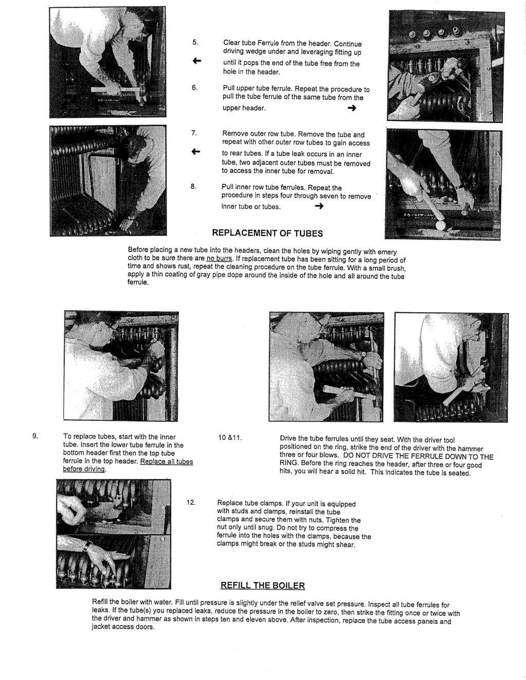
17 Page 17 of 28


18 Page 18 of 28
19 RV SERIES KNOCKDOWN PACKING LIST ORDER NO. MODEL NO. SERIAL NO. PACKING COMPLETE, INSPECTED AND APPROVED BY: LEADMAN FOREMAN Q.C. INSPECTOR (AT LEAST TWO SIGNATURES UIRED) DATE DATE DATE ATTENTION: 1) ONLY ONE BOILER TO BE KNOCKDOWN AND CRATED AT A TIME. 2) JACKET FRAME AND FLUE COLLECTOR TACK WELDS TO BE GROUND LOOSE TO DISASSEMBLY. NEVER USE HAMMER OR BEND METAL TO BREAK TACKS WELDS LOOSE. THIS CAUSES MIS- ALIGNMENT IN FIELD DURING REASSEMBLY. 3) THE FOLLOWING CHART INDICATES THE NUMBER OF BAGS OF REFRACTORY AND THE NUMBER OF MONOBLOCK PANELS UIRED FOR SHIPMENT PER MODEL. MODEL BAGS PANELS RV RV RV RV RV RV RV RV RV RV RV PROD. FORM. Q.C. 4) EVERY JOINT ON JACKET FRAME TO BE NUMBERED ACCORDING TO DRAWINGS B (WATER), AND B (STEAM). (B=BACK SIDE OF BOILER, D=DOOR PANEL SIDE, T=TOP OF BOILER, F= FRONT OF BOILER, R=REAR OF BOILER) 5) COLOR CODING COMPLETE, DOWN COMERS TO DOME AND RAIL, FLUE COLLECTOR END PANELS, SIDES AND TOP, SIDE TUBE PANEL FRAME ANGLES. (USE DIFFERENT COLORS FOR FRONT, REAR AND SIDE) 6) ALL JACKET PANELS ARE MARKED ON BACK SIDE INDICATING APPROXIMATE LOCATION. 7) ALL PAINTED PARTS TO BE SEPARATED BY PAPER OR CARD BOARD WHEN CRATING 8) ALL LOOSE PARTS MUST BE SECURED IN CRATES TO PREVENT DAMAGE DURING SHIPMENT. 9) CRATES ARE TO BE INITIALED BY FOREMAN OR Q.C. INSPECTOR WHEN CLOSED. CRATE NO. 1 INITIAL AT LEAST TWO ENTRIES PROD. FORM. Q.C. DESCRIPTION REMARKS BOILER BASE & FRAME (UPPER DOME HEADER BOLTED TO LOWER RAIL HEADER) TWO DOWNCOMERS (COLOR CODED) FOUR NEW GASKETS FOR DOWNCOMERS (METAL WOUND FOR HIGH PRESSURE) 72" ROLL OF YELLOW INSULATION CRATE NO. 2 BOILER TUBES, LIST NUMBER OF TUBES SHIPPED TUBE CLAMPS AND NUTS (PLACE IN SEALED BUCKET OR CAN INSIDE CRATE) PIPE LUBRICANT (FOR USE IN TAPERED TUBE HOLES) ONE TUBE DRIVER Page 19 of 28
20 CRATE NO. 3 CRATE NO. 4 CRATE NO. 5 CRATE NO. 6 ASSEMBLY INSTRUCTIONS & KNOCK DOWN VIDEO (MARK CRATE "VIDEO INSIDE") IM-11 INSTALLATION, OPERATION & SERVICE MANUAL, WIRING & DIMENSIONAL FLUE COLLECTOR ENDS HORIZONTAL TUBE BAFFLES 1st VERTICAL TUBE BAFFLE 2nd VERTICAL TUBE BAFFLE T BAFFLES FLANGE BOLTS AND NUTS FOR DOWNCOMERS MONO BLOCK INSULATION, LIST NUMBER OF PANELS SHIPPED BURNER CLAMPS AND NUTS BURNER PLUG BURNER PLUG CLAMPS AND NUTS PEEP SITE PLUG (REAR END) PEEP SITE PLUG CLAMPS AND NUTS PEEP SITE PLUG FIBERGLASS INSULATION ROPE DRAFT DIVERTER (IF UIRED) LIST DIAMETER SHIPPED DIA. BAROMETRIC (IF UIRED) LIST DIAMETER SHIPPED DIA. FLUE COLLECTOR TOP FLUE COLLECTOR SIDE PANELS (BACK) COMPLETE JACKET FRAME (NUMBERED) BAGS OF REFRACTORY (KAST-O-LITE #22), LIST NUMBER OF BAGS SHIPPED BUCKET(S) OF NEEDLES FOR REFRACTORY (MARK BUCKET "NEEDLES") ONE BUCKET OF T-36 CEMENT TUBE ACCESS PANELS, LIST NUMBER OF PANELS SHIPPED TUBE ACCESS PANEL ROPE GASKET SIDE TUBE PANEL FRAME ANGLES WITH STUDS TUBE PANEL CLAMP ANGLES FOR SECURING TUBE PANELS WHEN INSTALLED TUBE PANEL NUTS, WASHERS AND BOLTS TUBE PANEL SPACER FOR HINGE PANEL BURNER (FRONT) END JACKET BURNER (FRONT) END JACKET OVERLAYS PEEP SITE (REAR) END JACKET PEEP SITE JACKET OVERLAY (REAR END) PEEP SITE SWINGING COVER EXTRA INSULWOOL FOR BURNER PLUG AND PEEP SITE PLUG JACKET TOP PANELS JACKET TOP FILLER PANELS AND OVERLAYS UPPER FILLER PANELS JACKET SIDES (BACK) JACKET DOORS, LIST NUMBER SHIPPED. JACKET TRIM (CORNERS, CORNER MOLDINGS) JACKET SCREWS (BAGGED) TOUCH UP PAINT (GRAY) CONTROLS (HI LIMIT, OPERATOR) AND SENSOR BULBS CONTROL BOX / PANEL (PRE-WIRED) RELIEF VALVES (IF UIRED BUSHINGS) GAUGE GLASS SET (IF UIRED) FLOAT LOW WATER CUT OFF (IF UIRED PRE-PIPED) Page 20 of 28
21 PROBE TYPE LOW WATER CUT OFF SYPHON ASSEMBLY (IF UIRED PRE-PIPED) BLOW DOWN ASSEMBLY (IF UIRED PRE-PIPED) COMBUSTION CHAMBER DRAIN PIPE PRESSURE / TEMPERATURE GAUGE DRILL BITS GLUE (ONE QUART) FOR ROPE GASKET HEAT CONDUCTIVE COMPOUND FOR AQUASTATS ONE TUBE BRUSH ONE TUBE PULLER CRATE NO. 7 BURNER (PRE-WIRED) BURNER MANUAL BURNER GAUGE (INSTALLED) AIR SILENCER (IF UIRED) BURNER AND BURNER PLUG ROPE GASKET REMOTE OIL PUMP (IF UIRED PRE-PIPED) PILOT TUBE GAS TRAIN Page 21 of 28
22
23 EFF. DATE 8/26/05 ILLUSTRATED FORM: 2361 REPL. NEW PARTS LIST PAGE: RV W - 1 FOR RV-SERIES, WATER BOILERS RV350 THRU RV800 ORDERING INSTRUCTIONS WHEN ORDERING PARTS FOR YOUR BRYAN BOILER OR HEATER, BE SURE TO INCLUDE THE FOLLOWING INFORMATION: 1. QUANTITY OF ITEMS UIRED 4. BOILER MODEL NUMBER 2. PART NUMBER FROM THIS PARTS LIST (IF LISTED) 5. BOILER SERIAL NUMBER 3. DESCRIPTION OF PART 6. SHIPPING INSTRUCTIONS EXAMPLE PLEASE FORWARD TO US: FOR BOILER SHIP QTY. PART NO. DESCRIPTION MODEL SERIAL NO. VIA Boiler Tubes RV Freight Truck BRYAN BOILERS 783 N. CHILI AVE. * PERU * INDIANA * PHONE: * FAX: bryanboilers@iquest.net * INTERNET: Page 22 of 28
24 EFF.DATE: 8/26/05 RV - SERIES FORM: 2361 REPL.: NEW FORCED DRAFT - WATER PAGE: RV - W - 2 PARTS LIST RV350-S RV400-S RV450-S RV500-S RV550-S RV600-S RV700-S RV800-S DESCRIPTION PART NO. PART NO. PART NO. PART NO. PART NO. PART NO. PART NO. PART NO. ITEM 1 PRESSURE VESSEL - (With Tubes) CONSULT FACTORY BOILER BASE ASSEMBLY 2 Boiler Base Assembly Floor Insulation Block Refractory Cement (in pounds) BOILER TUBE ASSEMBLY 3 Boiler Tube Inside Assembly Boiler Tube Outside Assembly Boiler Tube Studs Tube Clamp Tube Clamp Nut TUBE BAFFLE ASSEMBLY 5 Tube Baffle Burner End Vertical Tube Baffle Peepsite End Vertical Tube Baffle Horizontal Tube Baffle Short Antibypass Tube Baffle Long Antibypass Tube "T" Baffle Assembly FLUE COLLECTOR PANELS 10 Flue Collector Side Starter Panel (Burner End) Flue Collector Side Filler Panel (Right Hand) Flue Collector Side End Panel (Right Hand) Flue Collector - Front Assembly Flue Collector - Rear Assembly Flue Collector Top/Stack Assembly Flue Collector Top Filler Panel(s) Flue Collector Wrap Insulation Flue Collector End Filler Panel Assembly (Front) Flue Collector End Filler Panel Assembly (Rear) Page 23 of 28
25 EFF.DATE: 8/26/05 RV - SERIES FORM: 2361 REPL.: NEW FORCED DRAFT - STEAM PAGE: RV - W - 3 PARTS LIST RV350-S RV400-S RV450-S RV500-S RV550-S RV600-S RV700-S RV800-S DESCRIPTION PART NO. PART NO. PART NO. PART NO. PART NO. PART NO. PART NO. PART NO. ITEM TUBE ACCESS DOOR 20 Tube Access Left (Starter) Panel Assembly Tube Access Center (Filler) Panel Assembly Tube Access Right (Hinged) Panel Assembly Tube Panel Clamp (Standard Horizonal) Tube Panel Clamp (Vertical) Tube Panel Clamp (Bottom Peepsite End) Tube Panel Clamp (Top Peepsite End) JACKET 27 Jacket Front Jacket Rear Jacket Side (Type A) Jacket Side (Type B) Jacket Top (Burner End) Jacket Top (Center) Jacket Top (Peepsite End) Jacket Door Top Filler Panel Assembly Jacket Corner Trim Jacket Side Horizontal Molding Jacket Front/Rear Molding Vertical Jacket Front/Rear Molding Horizontal Jacket Framework Assembly JACKET DOOR 40 Jacket Door Assembly Starter (Peepsite end) Jacket Door Assembly (Filler) Jacket Door Assembly (Second from Burner) Jacket Door Assembly (Burner End) BURNER ASSEMBLY BURNER - See Burner Parts Data Sheet REFER TO EQUIPMENT LIST Burner Plug Rope Gasket (Ft.) Page 24 of 28
26 EFF.DATE: 8/26/05 RV - SERIES FORM: 2361 REPL.: NEW FORCED DRAFT - STEAM PAGE: RV - W - 4 PARTS LIST RV350-S RV400-S RV450-S RV500-S RV550-S RV600-S RV700-S RV800-S DESCRIPTION PART NO. PART NO. PART NO. PART NO. PART NO. PART NO. PART NO. PART NO. ITEM PEEPSITE ASSEMBLY Fire Inspection Tube Nipple, 2" x 7" Pipe Cap 2" View Glass 1/4" x 2" Dia. Pyrex Rope Gasket 3/8" (ft.) STEAM TRIM Control Panel Terminal Strip * Gauge Glass Gauge Glass Valves Pressuretrol - Operator Pressuretrol - High Limit Low Water Cut Off & Pump Control REFER TO EQUIPMENT LIST Auxiliary Low Water Cut Off Try Cocks Pressure Gauge Pressure Relief Valve Pressure Shutoff Cock Blowdown Valves (Optional) SERVICE TOOLS Tube Puller ** Tube Driver ** Tube Brush *** * Depends on Number of Terminals Required ** Furnished as Standard on High Pressure Steam Only *** Not Standard. Available Upon Request. Page 25 of 28
27 Page 26 of 28
28 Page 27 of 28
29 Page 28 of 28
30

31
32


 previously used to drive 1 tubes will adequately drive 1 end-formed tubes only.")

33 Bryan Boilers Installation and Operating Service Manual Supplement Form # 2390 Date: 04/10/12 Replaces: 11/06/09 Bryan Boilers is currently supplying boilers with product enhancements to our flexible tubes. Most flexible tubes will no longer have a separate ferrule welded to each end. We have developed a way to form the ferrule from the tube material directly on the bent tube see figure 1. We will identify these tubes as End-Formed. Patent Pending A B C A B The new driver and current tube pullers will work for all tubes regardless if end-formed or welded ferrule. We have changed to end-formed tubes for the following boilers, DR, AB, RV, and RW. The Triple-Flex boiler has shipped with endformed tubes since introduction. The table below is provided as a crossreference until the parts list can be revised with the new numbers. A. 1 End-Formed Tube. B. Triple-Flex End-Formed Tube. C. 1-1/2 End-Formed Tube. These tubes will require a specific driver to install the tubes into the boiler vessel. The tube driver required is shown in Figure 2. This driver is required to drive all endformed tubes. The driver (see Figure 3) previously used to drive 1 tubes will adequately drive 1 end-formed tubes only. If you have a driver that looks like Figure 4 B, your driver will need to be modified by grinding to match Figure 4 A. NOTE: If you order tubes with old part number, you will receive end-formed tube replacements. End-Formed Tube Cross Reference Boiler Series Outside or Inside With Fittings (Old Part#) End-Formed (New Part#) DR Outside DR Inside CLM N/A CL N/A AB Outside AB Inside RV Outside RV Inside RW Outside RW Inside K Outside N/A K Inside N/A Tube Driver
34
CLM FORCED DRAFT STEAM BOILER
 FORM 1728 3/25/2004 CLM FORCED DRAFT STEAM BOILER TABLE OF CONTENTS 1. KNOCK-DOWN TYPES AND DEFINITIONS 1 2. BOILER FOUNDATION 1 3. BOILER FRAME & TUBE INSTALLATION 2 REFRACTORY TILE INSTALLATION 3 4.
CLM FORCED DRAFT WATER BOILER
 FORM 1728 3/25/2004 CLM FORCED DRAFT WATER BOILER TABLE OF CONTENTS 1. KNOCK-DOWN TYPES AND DEFINITIONS 1 2. BOILER FOUNDATION 1 3. BOILER FRAME & TUBE INSTALLATION 2 REFRACTORY TILE INSTALLATION 3 4.
Bryan Flexible Water Tube. Ultra-High Efficiency Condensing Hot Water Boilers. 3,000,000 BTUH Natural Gas Fired
 Form No. 8700 Bryan Flexible Water Tube TM Triple-Flex Series Ultra-High Efficiency Condensing Hot Water Boilers 3,000,000 BTUH Natural Gas Fired Minimum 90% Thermal Efficiency at 160 F Return with 20
USER S INFORMATION MANUAL
 USER S INFORMATION MANUAL HOT WATER HEATING BOILERS DOMESTIC WATER HEATERS 150,000-300,000 Btu/hr MODELS EB-EWU-02 IMPORTANT INSTALLER - AFFIX INSTALLATION MANUAL ADJACENT TO THE BOILER CONSUMER - RETAIN
TECHNICAL INSTRUCTIONS
 TECHNICAL INSTRUCTIONS 24-Month Maintenance Kit P/N 58025-06 For BMK2.0LN Boilers Description of Document: This TID provides the procedures to perform recommended 24-Month maintenance on the following
Bryan Water-Pak Indirect Systems 360,000 BTU to 4,500,000 BTU Inputs 199 to 3,533 Gallons Storage Capacity
 Form No. 2300-7 (Rev. 2/99) Gas, il or Dual Fuel Fired Bryan Water-Pak Indirect Systems 360,000 BTU to 4,500,000 BTU Inputs 199 to 3,533 Gallons Storage Capacity Originators of the Flexible Water Tube
Installation, Operation and Maintenance LOK-FLANGE Multitube Heat Exchangers
 Bulletin 1200/4 (Revised 5/12) Installation, Operation and Maintenance LOK-FLANGE Multitube Heat Exchangers INNOVATORS IN HEAT TRANSFER I. INSTALLATION OF HEAT EXCHANGERS A. HEAT EXCHANGER SETTINGS 1)
TECHNICAL INSTRUCTIONS
 TECHNICAL INSTRUCTIONS Benchmark 3.0LN 24-Month Maintenance Kit# 58015-04 This kit applies to units with an Ignitor and a separate gas injector. For units with an Ignitor-Injector (P/N 58023), see Kit
SAMPLE SPECIFICATIONS
 Page 1 of 6 3-03 SAMPLE SPECIFICATIONS The following sample specifications are provided by Superior Boiler Works to assist you in providing your customer with the specific needs for that application. The
Installation Instructions. For the 18 Built-In Dishwasher and Front Color Panels
 Installation Instructions For the 18 Built-In Dishwasher and Front Color Panels Printed in USA 154232102 Before You Begin DO NOT INSTALL DISHWASHER UNTIL YOU HAVE READ ALL INSTRUCTIONS. FOR YOUR SAFETY,
TECHNICAL INSTRUCTIONS
 TECHNICAL INSTRUCTIONS 24-Month Maintenance Kit P/N 58025-04 For BMK3.0LN Boilers Description of Document: This TID provides the procedures to perform recommended 24-Month maintenance on the following
Series 300 VTB. Installation Instructions
 Series 300 VTB Installation Instructions Sizes 7 12 16 20 30 HP #2 Fuel Oil Gas (500 to 2500 BTU) Gas Light Oil Combination High Pressure Steam Sizes 7 thru 16 HP (125 PSI) Sizes 20 and 30 HP (150 PSI)
TECHNICAL INSTRUCTIONS
 TECHNICAL INSTRUCTIONS 24-Month Maintenance Kit P/N 58015-02 For BMK2.0 (Nozzle Mix) Description of Document: This TID provides the procedures to perform recommended 24-Month maintenance on the following
MOHICAN. MOHICAN 4-Pass Water Boiler, HP, PSI Section
 SPECIFICATION SHEETS Steam Sample Specification Water Sample Specification MOHICAN SPECIFICATION SHEET The following sample specifications are provided by Superior Boiler Works to assist you in providing
Heat Exchanger Block Replacement Instructions
 Series 1-4 Gas-fired water boiler Heat Exchanger Block Replacement Instructions Ultra-80 S1-4 Heat Exchanger Block Replacement Kit, Part No. 383-500-773 Ultra-105 S1-4 Heat Exchanger Block Replacement
MODELS N150/300/675/900/1500/2500/2600 INSTALLATION, SERVICING AND MAINTENANCE INSTRUCTIONS
 MODELS N150/300/675/900/1500/2500/2600 INSTALLATION, SERVICING AND MAINTENANCE INSTRUCTIONS 1. FEATURES The Type N Trap range is particularly suitable for high pressure/high temperature trapping applications
PolyMax H2-24 Dutch Bucket System
 11234 PolyMax H2-24 Dutch Bucket System *Actual system may differ. PolyMax Dutch Buckets Versatile PolyMax Dutch Buckets are ideal for both small- and large-scale hydroponic growing. 2017 FarmTek All Rights
ALDRICH COMPANY THREE PASS FIRETUBE BOILER CLASSIC SERIES OPERATING & MAINTENANCE MANUAL
 ALDRICH COMPANY THREE PASS FIRETUBE BOILER CLASSIC SERIES OPERATING & MAINTENANCE MANUAL ALDRICH COMPANY 341 EAST WILLIAMS ST WYOMING, IL 61491 PH: 309-695-2311 FAX: 309-695-5779 1 General Information:
PVC Ductwork Model. Installation and Maintenance for
 Installation and Maintenance for PVC Ductwork Model WARNING! These installation instructions are for qualified and experienced technicians in the H.V.A.C. and Fire Protection field only. Failure to follow
Series 47 and 247 Mechanical Water Feeders. Series 47-2 and Combination Mechanical Water Feeder/Low Water Cut-Off ! WARNING
 Series 47 and 247 Mechanical Water Feeders McDonnell & Miller Installation & Maintenance Instructions MM-316(C) Series 47-2 and 247-2 Combination Mechanical Water Feeder/Low Water Cut-Off Series 47 Water
SERVICE TECHNICIAN ONLY read and follow completely.
 Parts list Table 7 Series 3 section and flue collector parts Item Description Part No. A Wide front section (7011) 316-700-245 B C D E Regular intermediate section (7015) Intermediate section w/draw rod
Revitalize Building Mechanical Systems (4619)
") SECTION 235216 FIRE-TUBE CONDENSING BOILERS PART 1 - GENERAL 1.1 RELATED DOCUMENTS A. Drawings and general provisions of the Contract, including General and Supplementary Conditions and Division 01 Specification
SECTION 235216 FIRE-TUBE CONDENSING BOILERS PART 1 - GENERAL 1.1 RELATED DOCUMENTS A. Drawings and general provisions of the Contract, including General and Supplementary Conditions and Division 01 Specification
Armstrong J Series Float, Thermostatic Steam Traps, Condensate Controllers & Liquid Drainers Installation and Maintenance Manual
 Armstrong J Series, Thermostatic Steam Traps, Condensate Controllers & Liquid Drainers Installation and Maintenance Manual This bulletin should be used by experienced personnel as a guide to the installation
TECHNICAL INSTRUCTIONS
 TID-0004_0A TECHNICAL INSTRUCTIONS Hardware Procedure: Coil and Riser Replacement Procedures for All Styles of A, B, C, and D Indirect-Fired Water Heaters Applies to: Indirect-Fire Water Heaters. Description
High Efficiency Oil Fired Hot Water Boiler REPAIR PARTS & OPTIONAL KITS. P/N# , Rev. C [01/09]
![High Efficiency Oil Fired Hot Water Boiler REPAIR PARTS & OPTIONAL KITS. P/N# , Rev. C [01/09]](/thumbs/93/114021062.jpg "High Efficiency Oil Fired Hot Water Boiler REPAIR PARTS & OPTIONAL KITS. P/N# , Rev. C [01/09]") High Efficiency Oil Fired Hot Water Boiler REPAIR PARTS & OPTIONAL KITS P/N# 240007518, Rev. C [01/09] JACKET 3 5 8 10 7 9 4 6 1 11 Key Description 4 section 5 section 6 section 7 section Complete Jacket
High Efficiency Oil Fired Hot Water Boiler REPAIR PARTS & OPTIONAL KITS P/N# 240007518, Rev. C [01/09] JACKET 3 5 8 10 7 9 4 6 1 11 Key Description 4 section 5 section 6 section 7 section Complete Jacket
STORAGE TANK INSTALLATION and OPERATION MANUAL
 LST-I-O 100161529_2000014416 Rev F STORAGE TANK INSTALLATION and OPERATION MANUAL LOW LEAD CONTENT The information contained in this manual is intended for use by qualified professional installers, or
Technical Data TYPE T14 & T14D TEMPERATURE PILOT SPENCE ENGINEERING COMPANY, INC. 150 COLDENHAM ROAD, WALDEN, NY SD 4511A T14 PILOT
 Technical Data SD 4511A SPENCE ENGINEERING COMPANY, INC. 150 COLDENHAM ROAD, WALDEN, NY 12586-2035 TYPE T14 & T14D TEMPERATURE PILOT PRINTED IN U.S.A. SD 4511A/9811 5 13 /16 D 4 7 /8 1 13 /16 T14 PILOT
www. ElectricalPartManuals. com \/' INSTRUCTIONS WESTINGHOUSE RADIATORS DESCRIPTION '- INSTALLATION MAINTENANCE
 FIG. 1. Westinghouse Single Radiators Mounted Perpendicular to the Wall of a Rectangular Tank on a 6,000 KVA Transformer THE WESTINGHOUSE RADIATOR is a highly efficient cooling unit which is designed for
650A/6500A MILLS BOILER
 650A/6500A BOILER 650A/6500A MILLS BOILER INSTALLATION INSTRUCTIONS 6500-IOM-3 Page 1 STEAM OR WATER HEATING FOR AUTOMATIC FIRING WITH OIL OR GAS DESIGNED AND TESTED ACCORDING TO A.S.M.E. BOILER AND PRESSURE
Installation and maintenance instructions
 6303 88 07/2005 For heating engineers Installation and maintenance instructions Oil and gas-fired boilers Logano G25 US Please read carefully prior to installation and maintenance Table of Content Safety
Installation Instructions
 Installation Instructions KFN 9855 ide en - CA Installation, repair and maintenance work should be performed by a Miele authorized service technician in accordance with national and local safety regulations
GE Monogram. Installation. Instructions. Stainless Steel Bottom Mount Built-In Refrigerators. Models ZICS36N RH ZICS36N LH
 GE Monogram Installation Instructions Stainless Steel Bottom Mount Built-In Refrigerators Models ZICS36N RH ZICS36N LH Before you begin - Read these instructions completely and carefully. IMPORTANT - Save
Series. Gas/Oil Boilers Water. Oil, Gas & Installation, Operation & Maintenance Manual
 Series Oil, Gas & LC Gas/Oil Boilers Water Installation, Operation & Maintenance Manual TABLE OF CONTENTS TABLE OF CONTENTS USING THIS MANUAL A. INSTRUCTION MANUALS............... B. SPECIAL ATTENTION
Installation Instructions Built-In Dishwasher
 GE Consumer & Industrial Appliances Installation Instructions Built-In Dishwasher If you have questions, call 800.GE.CARES (800.432.2737) or visit our website at: www.ge.com BEFORE YOU BEGIN Read these
TECHNICAL DATA. Wet 26a. February 22, 2009
 February 22, 2009 Wet 26a 1. DESCRIPTION The Viking Alarm Check Valve serves as a check valve by trapping pressurized water above the clapper and preventing reverse flow from sprinkler piping. The valve
Built-In Dishwasher. Installation Instructions. BEFORE YOU BEGIN Read these instructions completely and carefully. IMPORTANT The dishwasher MUST be
 Installation Instructions Built-In Dishwasher If you have questions, call 800.GE.CARES (800.432.2737) or visit our website at: www.ge.com BEFORE YOU BEGIN Read these instructions completely and carefully.
HORIZONTAL FIRE TUBE BOILERS Piping (HVAC) Pumping Equipment (HVAC).
 Pumping Equipment (HVAC).") SECTION 15555 HORIZONTAL FIRE TUBE BOILERS PART 1 GENERAL 1.01 SUMMARY A. Related Sections: 1. 15510 - Piping (HVAC). 2. 15540 - Pumping Equipment (HVAC). 1.02 SUBMITTALS A. Submit properly identified
SECTION 15555 HORIZONTAL FIRE TUBE BOILERS PART 1 GENERAL 1.01 SUMMARY A. Related Sections: 1. 15510 - Piping (HVAC). 2. 15540 - Pumping Equipment (HVAC). 1.02 SUBMITTALS A. Submit properly identified
IH091: Home Wastewater Disposal System Installation Instructions & Warranty Information
 IH091: Home Wastewater Disposal System Installation Instructions & Warranty Information The Environment One grinder pump is a well-engineered, reliable and proven product. Proper installation ensures years
UMA-1020 Light Weight Suspended Ceiling Kit
 INSTALLATION INSTRUCTIONS UMA-1020 Light Weight Suspended Ceiling Kit The provides a sturdy support for LCD/DLP hanging brackets (and certain other products weighing less than 50 pounds) when installing
WGO Series 3 Section Assembly
 WGO Series 3 Section Assembly 0 Current Service Parts WGO Series 3 Section Assembly Fig. Part Description Casting Notes A 3670070 FRONT SECTION, w/envelope, fits Series,, & 3 70 Boiler Size 3 5 6 7 B 36700065
Form 2143 Date: 4/3/03 Repl: 2/1/99 BRYAN STEAM LLC. Installation and Operating Service Manual BOILER FEED SYSTEM
 0 Form 2143 Date: 4/3/03 Repl: 2/1/99 BRYAN STEAM LLC Installation and Operating Service Manual BOILER FEED SYSTEM INSTALLATION AND OPERATION SERVICE MANUAL BOILER FEED SYSTEM Bryan Steam LLC 783 North
INSTALLATION, OPERATION AND MAINTENANCE MANUAL FOR COMMERCIAL INDIRECT POWERED WATER HEATER
 INSTALLATION, OPERATION AND MAINTENANCE MANUAL FOR COMMERCIAL INDIRECT POWERED WATER HEATER ELECTRIC HEATER COMPANY BASE MODEL T Edition 0 HUBBELL ELECTRIC HEATER COMPANY P.O. BOX 88 STRATFORD, CT 0665
Installation Manual PS-225 & PS-275
 Installation Manual PS-225 & PS-275 Table of Contents Pre-Uncrating Checklist... 1 Verifying System Requirements... 2 Verifying System Direction... 2 Verifying the Electrical Requirements... 2 Removal
User s Information Manual
 Gas-fired Water boiler Series 2 NOTICE: Series 1/Series 2 identification Read the boiler rating plate to determine the series number. The rating plate is located on the right side of the boiler. User s
Instruction Manual HWR MODEL RESISTO-FLO ELECTRIC BOILER
 Page 1 of 16 Instruction Manual HWR MODEL RESISTO-FLO ELECTRIC BOILER Page 2 of 16 FOREWORD The HWR Resisto-Flo Electric Hot Water Boiler is designed to provide a compact packaged unit requiring a minimum
Modular Drawer Cabinets Installation Instructions
 Modular Drawer Cabinets Installation Instructions IMPORTANT PRODUCT LIABILITY INFORMATION Read all instructions before proceeding with installation or drawer loading. Vital product information pertaining
215 Gallon Waste Oil Tank With Bypass Regulator Installation Instructions
 215 Gallon Waste Oil Tank With Bypass Regulator Installation Instructions Lanair Products LLC 4109 Capital Circle Janesville, Wisconsin 53546 1-888-370-6531 www.lanair.com BEFORE YOU BEGIN INSTALLATION...
Installation Instructions
 Installation Instructions Downdraft Vent Systems PVB94 PVB98 ZVB30 ZVB36 31-10728-8 11-14 GE 1 Safety Information If you have questions, call 800.GE.CARES or visit our website at: GEAppliances.com BEFORE
Media Service Instructions 1500 Series BAT Media Plants
 R Media Service Instructions 1500 Series BAT Media Plants J-500 MEDIA SERVICE Read these instructions and perform every step. After servicing 2 or 3 installations, you will only have to refer to these
SECTION STEAM CONDENSATE PUMPS
 PART 1 - GENERAL 1.1 DESCRIPTION SECTION 23 22 23 STEAM CONDENSATE PUMPS SPEC WRITER NOTES: 1. Delete between // ---- // if not applicable to project. Also delete any other item or paragraph not applicable
 www.whitakerbrothers.com The Challenge Machinery Company provides owner's manuals on its products solely as a courtesy to its customers. See the information below before using this manual. These manuals
General System Layout Sketch
 General System Layout Sketch EZ-37 Solar Panels PV panel Glycol Fill Valve Expansion Tank ` 1 Introduction This document describes how to install a Heliatos GH type solar water heating system. These systems
Columbia Boiler Company
 EMG Series Boilers Available in Natural Gas & Propane Rev 12012 Columbia Boiler Company PO Box 1070 Pottstown, PA 19464 Tel (610) 473-8457 Fax (610) 367-6800 Website www.columbiaboiler.com Email cbcsales@ptd.net
Gen II Entree Bath - All Models
 Gen II Entree Bath - All Models Installation Manual Important Safety Instructions Read & Follow All Instructions Thoroughly Important safety instructions. Read and follow all instructions thoroughly. CAUTION:
Installation Instructions
 GE Consumer & Industrial Appliances Installation Instructions Junction Box Cover Within this user bag, you will find a junction box cover and a #10 hex head screw used to attach the junction box cover
OP44-1 REV 2: Removed depiction of air intake hole in the CB-907A Right Aft Case Baffle.
 REVISION DESCRIPTION: OP44-1 REV 2: Removed depiction of air intake hole in the CB-907A Right Aft Case Baffle. OP44-4 REV 1: Steps rewritten to describe the air intake hole on the CB-907A Right Aft Case
Clean Water Made Easy. CWS Time Clock Softener Installation & Start Up Guide. Questions?
 Clean Water Made Easy www.cleanwaterstore.com CWS Time Clock Softener Installation & Start Up Guide Thank you for purchasing a Clean Water System! With proper installation and a little routine maintenance
INSTALLATION, OPERATING & MAINTENANCE INSTRUCTIONS FOR 350 SERIES CIRCULATION HEATERS
 INDEECO Circulation Heaters are designed to provide years of trouble free operation if properly installed and maintained. Please read and follow these instructions for installing and maintaining the heater.
Boiler Manual. Oil-Fired Steam Boilers. Maintenance Parts. Installation Startup
 Oil-Fired Steam Boilers Boiler Manual Installation Startup Maintenance Parts This manual must only be used by a qualified heating installer/service technician. BEFORE installing, read all instructions
BUILT-IN DISHWASHER INSTALLATION INSTRUCTIONS
 BUILT-IN DISHWASHER INSTALLATION INSTRUCTIONS PLEASE READ COMPLETE INSTRUCTIONS BEFORE YOU BEGIN LEAVE INSTALLATION INSTRUCTIONS AND USER'S GUIDE WITH OWNER ALL ELECTRIC WIRING AND PLUMBING MUST BE DONE
Installation and Operating Instructions ISH ELECTRIC STEAM SUPERHEATER
 Installation and Operating Instructions ISH ELECTRIC STEAM SUPERHEATER 1 Installation and Operating Instructions ISH ELECTRIC STEAM SUPERHEATER FOR YOUR SAFETY This manual supplies information on the application,
In-Wall Slide-out OEM INSTALLATION MANUAL. In-Wall Slide-out OEM Installation Manual
 In-Wall Slide-out OEM INSTALLATION MANUAL Rev: 01.22.2018 In-Wall Slide-out OEM Installation Manual TABLE OF CONTENTS Safety and System Information 2 In-Wall Slide-Out Chassis Specification 3 6.1.1 Slide-Out
Boiler Manual. Series 3 Water & steam boilers for use with Gas, Light Oil, & Gas/Light Oil Fired Burners. Maintenance Parts. Installation Startup
 94 Series 3 Water & steam boilers for use with Gas, Light Oil, & Gas/Light Oil Fired Burners Boiler Manual Installation Startup Maintenance Parts For additional information, refer to.. Burner specification
mith Mills 4500A Smith Mills 4500A 4500A-3R OIL, GAS OR COMBINATION GAS/OIL COMMERCIAL BOILER/BURNER CAST IRON
 Mills 00A mith Mills 00A Smith CAST IRON OIL, GAS OR COMBITION GAS/OIL COMMERCIAL BOILER/BURNER 00AR STEAM GAUGE OPERATING CONTROL MODULATING CONTROL HI LIMIT PRESSURE CONTROL 0" STEAM DRUM TEST COCK /"
Installation Instructions Part No , Part No Part No
 Torsion-Flex Motor mount for PSC motors and Rigid-Mount for ECM motors Replacement Kit Cancels: New Installation Instructions Part No. 327752-401, Part No. 327753-401 Part No. 327754-401 IIK-310A-45-11
72 ONYX XL FLAT PANEL ELECTRIC FIREPLACE
 72 ONYX XL FLAT PANEL ELECTRIC FIREPLACE Model Numbers: 80005 OWNER S MANUAL WARNING Read and understand this entire owner s manual, including all safety information, before plugging in or using this product.
ENRGY CURB APPLICATION GUIDE FOR TPO ROOFING SYSTEMS
 1. Introduction The ENRGY Curb mounting system is a lightweight, nonpenetrating, roof-integrated, photovoltaic (PV) mounting system designed to maintain roof integrity and maximize power density. This
Patterson/AMT Inline Circulator Pump Refer to pump manual for General Operating and Safety Instructions.
 Please read and save this Repair Parts Manual. Read this manual and the General Operating Instructions carefully before attempting to assemble, install, operate or maintain the product described. Protect
I-VICFLEX.AB4. Victaulic VicFlex Style AB4 Sprinkler Fitting for Hat Furring Channel Ceiling Systems WARNING INSTALLATION INSTRUCTIONS
 INSTALLATION INSTRUCTIONS I-VICFLEX.AB Victaulic VicFlex Style AB Sprinkler Fitting for Hat Furring Channel Ceiling Systems Read and understand all instructions before attempting to install any Victaulic
Installation Instructions
 Installation Instructions For the 18" Built-In Dishwasher Sears, Roebuck and Co. Sears Canada, Inc. Hoffman Estates, IL 60179 U.S.A. Toronto, Ontario, Canada M5B 2B8 154435201 Before You Begin DO NOT INSTALL
Description Model Weil-McLain part number. Vent Termination Kit for 3" Stainless Steel All
 Replacement parts Figure 96 Miscellaneous parts Description Model Weil-McLain part number Vent Termination Kit for 3" PVC All 383-500-397 Vent Termination Kit for 3" Stainless Steel All 382-200-430 Vent
HX Field Replacement Kit
 Quantity Kit Part Number Description PE 110 Natural Gas Stainless Steel Condensate Pan PT 110 Natural Gas Polypropylene Condensate Pan Model PE 110 LP Stainless Steel Condensate Pan PT 110 LP Polypropylene
SECTION HEATING BOILER FEEDWATER EQUIPMENT
 SECTION 23 53 00 HEATING BOILER FEEDWATER EQUIPMENT PART 1 - GENERAL 1.1 SUMMARY A. Section includes boiler feedwater pumps, de-aerators, accessories, controls and tanks. 1.2 REFERENCES A. ASME (American
13-1. Temperature Regulator
 -1 Step 0 Type/Structure/Features Please refer to this for type, structure and features of. Step 1 Selection Please look at the ID chart to choose the right products depending on the intended uses. Details
Dishwasher Installation Instructions DW 24XT/DW 24XV
 Dishwasher Installation Instructions DW 24XT/DW 24XV Installation Instructions Dishwasher BEFORE YOU BEGIN Read these instructions completely and carefully. IMPORTANT Observe all governing codes and ordinances.
Installation Instructions
 Installation Instructions Outdoor Installation Kit Models AD250 & AW250 Part No. 24097 Qualifications for installation of the kit: You must be able to read and understand all instructions provided with
Installation Instructions
 Installation Instructions Built-In Dishwasher If you have questions, call 800-GECARES or visit our website at: www.geappliances.com BEFORE YOU BEGIN Read these instructions completely and carefully. IMPORTANT
SECTION HEATING BOILERS
 SECTION 23 52 00 HEATING BOILERS PART 1 - GENERAL 1.1 SUMMARY A. Section includes boilers, controls and boiler trim, steam and condensate connections, hot water connections, fuel burning system and connections,
PolyMax H1-10 Dutch Bucket System
 112529 PolyMax H1-10 Dutch Bucket System *Actual system may differ. PolyMax Dutch Buckets Versatile PolyMax Dutch Buckets are ideal for both small- and large-scale hydroponic growing. STK# DIMENSIONS 112529
INSTALLATION AND OPERATING INSTRUCTIONS GN2. HIGH EFFICIENCY CAST IRON BOILER FOR LIQUID and/or GAS FUELS
 INSTALLATION AND OPERATING INSTRUCTIONS HIGH EFFICIENCY CAST IRON BOILER FOR LIQUID and/or GAS FUELS INDEX 1. Technical information... page 3 2. Dimensional and technical characteristics... page 3 3. Packing
Installation Instructions
 Wood Blinds Installation Instructions Heartland Woods Heartland Woods w/ Continuum *Click on any page to return to the Table of Contents* Heartland Woods Wood Blinds Mounting Inside or Outside Window Frame
TC II. Series. Oil, Gas & Gas/Oil Boilers. Installation, Operation & Maintenance Manual
 Series Oil, Gas & TC II Gas/Oil Boilers Installation, Operation & Maintenance Manual TABLE OF CONTENTS TABLE OF CONTENTS USING THIS MANUAL 1 A. MANUAL ORGANIZATION..............1 B. SPECIAL ATTENTION BOXES............1
Guidelines for Earthquake Bracing of Residential Water Heaters
 Guidelines for Earthquake Bracing of Residential Water Heaters Department of General Services Division of the State Architect 1102 Q Street, Suite 5100 Sacramento, CA 95814 Phone: (916) 324-7099 Fax: (916)
INSTALLATION AND MANINTENANCE INSTRUCTIONS
 INSTALLATION AND MANINTENANCE INSTRUCTIONS Appr. Nr. A 9503 T - 0085 AQ 0765 PEGASUS F2 T HIGH EFFICIENCY GAS-FIRED CAST-IRON BOILERS Models 51-68 - 85-102 2 Contents 1. General technical data 2. Dimensional
Replacement parts EG/PEG
 Replacement parts EG/PEG Table 13 EG/PEG replacement parts A B Left hand end section with heater opening (Pattern No. 1814) Left end section without heater opening(pattern No. 1813) Right hand end section
Installation and Maintenance "L" and "LS" Series
 Installation and Maintenance "L" and "LS" Series IB-43-E This bulletin should be used by experienced personnel as a guide to the installation and maintenance of "L" and "LS" Series ultra capacity float
LGB Gas fired boiler
 LGB Gas fired boiler Control Supplement LGB-5 Series 2 Propane gas CSD-1 Control System Part Number 550-110-682/0304 Please read this page first Hazard definitions To the installer... The following terms
Wall Mount Electric Fireplace
 Wall Mount Electric Fireplace User Guide Thank you for purchasing the Ivation Wall Mount Electric Fireplace. This User Guide is intended to provide you with guidelines to ensure that operation of this
Installation Manual PS-200 & PS-201
 Installation Manual PS-200 & PS-201 Table of Contents Pre-Uncrating Checklist... 1 Verifying System Requirements... 2 Verifying System Direction... 2 Verifying the Electrical Requirements... 2 Removal
BASE-RAY CAST IRON BASEBOARD RADIATION
 INSTALLATION MANUAL FOR BASE-RAY CAST IRON BASEBOARD RADIATION TABLE OF CONTENTS PAGE 2 RATINGS 4 ASSEMBLY CHART 5 SYSTEM TYPES 6 SERIES LOOP SYSTEMS 7 SERIES LOOP DESIGN 8 INSTALLATION DETAILS 9 INSTALLATION
Reverse Osmosis Install Guide
 Reverse Osmosis Install Guide Written by 602abcWATER Start Here Step 1 Con irm All Product Components Open your packages and con irm that you have received all the correct components. If you are missing
CMA-440 Light Weight Suspended Ceiling Kit
 INSTALLATION INSTRUCTIONS CMA-440 Light Weight Suspended Ceiling Kit The provides a sturdy support for LCD/DLP hanging brackets (and certain other products weighing less than 50 pounds) when installing
DENVER PUBLIC SCHOOLS DESIGN AND CONSTRUCTION STANDARDS This Standard is for guidance only. SECTION PUMPS
 PART 0 A/E INSTRUCTIONS 0.01 Design Requirements A. Pumping system design 1. A primary-secondary pumping system is preferred. Redundant pipes are required for chillers and boilers. 2. Select pumps to operate
ELECTRIC FLAT PANEL FIREPLACE HEATER
 ELECTRIC FLAT PANEL FIREPLACE HEATER Model Numbers: 80-2000A-42 OWNER S MANUAL AC 120V 60Hz 1500W WARNING Read and understand this entire owner s manual, including all safety information, before plugging
Shay Plumbing IX - Feed Water Pipes
 Shay Plumbing IX - Feed Water Pipes Nelson Riedel Nelson@NelsonsLocomotive.com Initial: 11/28/03 Last Revised: 06/06/2004 Feed Water Pipe Orientation: Photos of a couple of the Cass shays were reviewed
Boiler Manual. Water & steam boilers Series 2 for use with Gas, Light Oil, & Gas/Light Oil Fired Burners. Burner specification and data sheets
 88 Water & steam boilers Series 2 for use with Gas, Light Oil, & Gas/Light Oil Fired Burners Boiler Manual For additional information, refer to.. Burner specification and data sheets for burners pre-tested
Series 1140 and 1141 Temperature Regulators
 Hoffman Specialty Installation & Maintenance Instructions HS-504(E) Series 1140 and 1141 Temperature Regulators! CAUTION FOLLOW ALL INSTALLATION AND OPERATING INSTRUCTIONS. TURN OFF WATER OR STEAM BEFORE
OPERATING AND MAINTENANCE MANUAL FOR PLATE HEAT EXCHANGER INDIRECT FIRED WATER HEATER. Electric Heater Company Base Model "BWXP"
 OPERATING AND MAINTENANCE MANUAL FOR PLATE HEAT EXCHANGER INDIRECT FIRED WATER HEATER Electric Heater Company Base Model "BWXP" HUBBELL ELECTRIC HEATER COMPANY P.O. BOX 288 STRATFORD, CT 06615 PHONE: (203)
Ca 6s and BCa 6s kw INSTALLATION AND OPERATING INSTRUCTIONS. Page 1 31/07/00
 Ca 6s and BCa 6s 33-64 kw INSTALLATION AND OPERATING INSTRUCTIONS Page 1 CONTENTS: General specification Dimensions for Ca6s and BCa6s boilers. Boiler room clearance requirements Boiler block assembly
WAILEA OWNER S MANUAL
 WAILEA OWNER S MANUAL The blades in each pack are matched for equal weight to assure smooth fan operation. If more than one fan is being installed, be careful not to mix blades from different cartons.