Part 1: class 69 operating instructions
|
|
|
- Christal Tamsin Morris
- 5 years ago
- Views:
Transcription
1 Contents Page: Preface and general safety instructions Part 1: class 69 operating instructions 1. Product description Designated use Subclasses 3.1 Optional extras Technical data Operation 5.1 Folding down left-hand half of table plate (MG 56-2 frame only) Threading the needle thread Subclass Subclass 69-FA Adjusting the needle-thread tension Opening the needle-thread tensioner Winding on the looper thread Fitting the looper-thread bobbin Adjusting the looper-thread tension Fitting and changing the needle Lifting the sewing feet Locking the sewing feet in the raised position Adjusting the sewing-foot stroke Adjusting the sewing-foot pressure Adjusting the stitch length Welting Ribbon binder (class ) Control unit and operating panel 6.1 General Efka VD554KV/6F82AV sewing drive Control-box buttons Altering parameter values Quick QD554/A51K01 sewing drive Operating-panel buttons Altering parameter values
2 Contents Page: 7. Sewing Maintenance Cleaning and testing Lubrication Optional extras HP 11-1 pneumatic rapid stroke adjuster
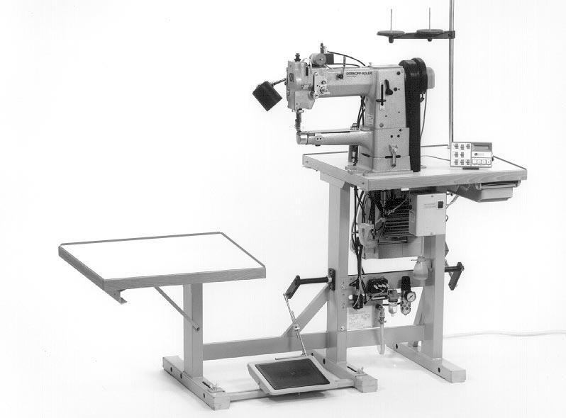
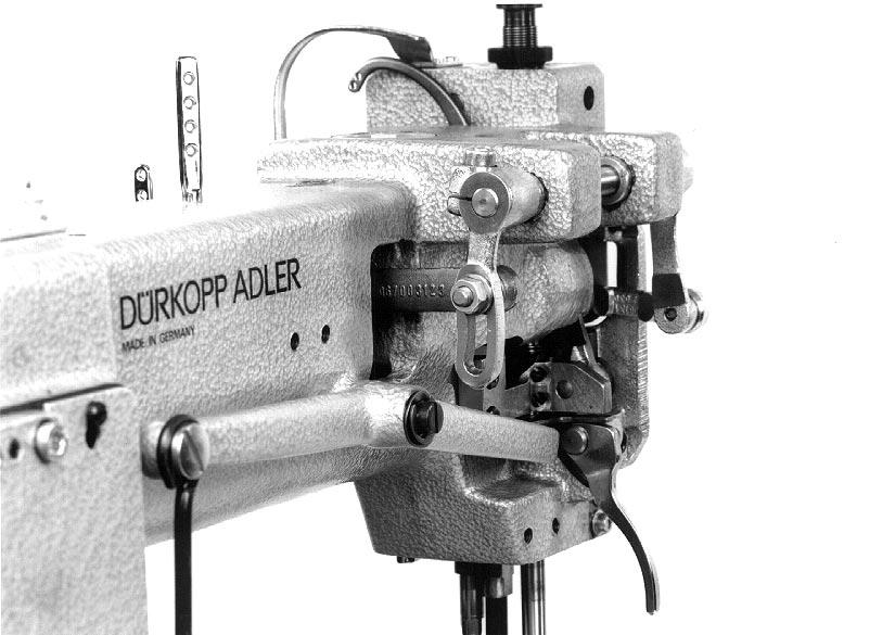
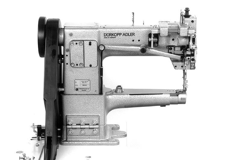
3 1. Product description The DÜRKOPP ADLER 69 is an all-purpose special sewing machine. Double-lockstitch free-arm machine with underfeed, needle feed and alternating foot overfeed. Depending on the subclass, a single-needle machine with or without thread clipper beneath the needle plate. Slim free arm with large passage space and large sewing-foot stroke. Maximum passage space beneath raised sewing feet: 12 mm (with sewing-foot-raising knee lever). Small horizontal shuttle. The sewing machine can be supplied with a closed, cut-out or fold-down left-hand table-plate half. The fold-down version permits the unobstructed manipulation of large items round the free arm. Smooth, draw-free edging and precision sewing of inner and outer arcs by an integral follow binder mechanism. Knee-operated pneumatic rapid stroke-adjustment mechanism to switch the foot overfeed to maximum sewing-foot stroke (optional extra). 2. Designated use The 69 is a special sewing machine designed to be used to sew light to medium-heavy materials. As a rule such material consists of textile or synthetic fibres, but it also includes leather. These materials are used in the clothing, footwear and leatherwear industries, as well as in domestic and automobile upholstery. This special sewing machine can also be used to execute so-called technical seams. However, the operator must carry out an assessment of the possible dangers (with which DÜRKOPP ADLER AG would be happy to assist), as such applications are comparatively unusual and they are potentially of enormous diversity. Depending on the outcome of this assessment it may be necessary to take special safety precautions. Generally speaking material processed with this special sewing machine must be dry, its thickness when compressed by the lowered sewing feet must not exceed 7 mm and it must contain no hard objects, since otherwise the operator of the machine would have to wear protective goggles (which cannot at present be supplied). The seam is generally executed with textile-fibre sewing threads up to 30/3 NeB (cotton yarns), 40/3 Nm (synthetic yarns) or 30/3 Nm (covering yarns) in size. The use of any other threads must also be subject to an assessment of the risks involved and the taking of any necessary safety precautions. The premises in which this special sewing machine is set up and operated must be dry and well-maintained. If it is to be used in premises which are not dry and well-maintained, special precautions may be necessary: these must be the subject of an agreement (see EN :1990). As manufacturers of industrial sewing machines we work on the assumption that personnel working on our machines will be at least semi-skilled, so that they can be presumed to be familiar with all normal operations and with the dangers inherent in them. 5
4 3. Subclasses class : class 69-FA-373: single-needle double-lockstitch free-arm sewing machine with underfeed, needle feed and alternating-foot overfeed as class , but with electromagnetic thread clipper beneath the needle plate 3.1 Optional extras order no. FLP 14-2 RAP 14-1 HP 11-1 WE-6 optional extra electro-pneumatic sewing-foot-raising mechanism pedal-operated. electro-pneumatic bar-tack and sewing-foot-raising mechanism pedal-operated. Pneumatic rapid stroke-adjustment mechanism for the overfeed knee-operated. Maintenance unit For pneumatic optional extras Pneumatic connection pack For the pneumatic connection of frames with the maintenance unit and pneumatic optional extras. Consisting of connecting hose (length 5 m, diameter 9 mm), connectors, bands, coupler plug and socket Halogen lamp WALDMANN, with 12V/20W bulb, attached to the upper part of the machine Lamp transformer For 230V, with mains connector, without switch, for and lamps Lamp-attachment set For lamp. 4. Technical data Lc noise-level indicator: workplace-related emission valuein accordance with DIN A-1-KL2 Lc = 81 db (A) class: , 69-FA-373 stitch length: 4 mm sewing-foot stroke: 3.2 mm stitch rate: 1700 [min -1 ] material: double Skai 1.6 mm 900 g/m 2 DIN
5 Needle system: 134 Needle thickness (depending on E no.) [Nm] Maximum sewing-thread thicknesses: - cotton [NeB] 30/3 - synthetic endless [Nm] 40/3 - covering yarn [Nm] 30/3 stitch rate: - maximum [min -1 ] ex works [min -1 ] 1700 maximum stitch length: - forwards [mm] 5 - backwards [mm] 5 maximum sewing-foot stroke: [mm] 7 maximum passage space beneath raised sewing feet: - sewing foot raised by lifting lever [mm] 7 - sewing foot raised by knee lever [mm] 12 operating pressure: [bar] 6 rated voltage: 3 x V, 50/60 Hz 3 x V, 50/60 Hz dimensions: - MG 53-3 frame (H x W x D) [mm] 1540 x 1060 x MG 56-2 frame (H x W x D) [mm] 1560 x 1200 x 600 working height:... - MG 53-3 frame [mm] MG 56-2 frame [mm] 780 weight (upper part only): ca. [kg] 33 7

6

7 5. Operation 5.1 Folding down left-hand half of table plate (MG 56-2 frame only) When the special sewing machine is fitted with the MG 56-2 frame the table plate consists of two parts. The left-hand half 3 can be folded down to permit the unobstructed manipulation of large items round the free arm Folding down the left-hand half of the table plate Turn fasteners 7 and 8 beneath the table plate anticlockwise to unlock the left-hand half 3 of the table plate. Fold the left-hand half 3 of the table plate down and to the left. Hook shackle 1 onto the pin 2 of the left-hand frame upright. Folding the left-hand half of the table plate back into place Unhook shackle 1 from pin 2. Lift the left-hand half 3 of the table plate, swivel it to the right and lower it onto support plates 5 and 6. The pins 4 in the right-hand half of the table plate must fit into the holes in the left-hand half 3. Turn fasteners 7 and 8 beneath the table plate clockwise to lock the left-hand half 3 of the table plate. 9
8 5.2 Threading the needle thread Subclass Caution: danger of injury Turn off the main switch The needle thread may only be threaded with the sewing machine turned off. 10
9 5.2.2 Subclass 69-FA-373 Caution: danger of injury Turn off the main switch The needle thread may only be threaded with the sewing machine turned off. 11

10 1 2 3 Fig. a: Fig. b: correct thread loop in the centre of the material needle-thread tension too weak or looper-thread tension too strong Fig. c: needle-thread tension too strong or looper-thread tension too weak 12
11 5.3 Adjusting the needle-thread tension Pre-tensioning mechanism (subclass 69-FA-373) On subclass 69-FA-373 the needle thread needs to be under residual tension for the thread cutter to function reliably when the main tensioner 2 is open. This residual tension is created by the pre-tensioning mechanism 1. The pre-tensioning mechanism 1 also determines the length of the needle-thread end after the thread has been clipped. The pre-tension 1 should be set lower than the main tension 2. Adjust pre-tensioning mechanism 1 by turning the knurled nut. After major changes to preliminary tension 1 the main tension 2 should also be adjusted accordingly. Main tension The main tension 2 should be set as low as possible. The looping of the threads must be in the centre of the material (see fig. a). With thin material excessive thread tension can cause unwanted gathering and thread breakage. Adjust the main tensioner 2 so that the stitches are uniform. 5.4 Opening the needle-thread tensioner Automatic The main tensioner 2 is opened automatically: when the thread is severed (subclass 69-FA-373). when the foot is raised (pedal 1 position backwards) Manual The main tensioner 2 is opened manually: when the release lever 3 is pressed towards the arm. The main tensioner 2 remains open for as long as pressure is maintained on the release lever 3. when the sewing feet are raised mechanically with the knee lever (see chapter 5.9). when the sewing feet are locked in the raised position (see chapter 5.10). 13

12
13 5.5 Winding on the looper thread Caution: danger of injury Turn off the main switch. The looper thread may be threaded for winding on only when the sewing machine is switched off. When winding on for sewing with no underlay material: arrest the sewing feet in the up position (see chapter 5.10). Thread looper thread as shown in the upper illustration. Wind about 5 coils of looper thread clockwise onto the bobbin core. Place bobbin 3 on bobbin-winder shaft 5. Swivel bobbin-winder lever 4 against the bobbin. The bobbin-winder wheel 2 is pressed against the V-belt. Adjust tension 1. The looper thread should be wound on with minimal tension. Sew. The bobbin-winder lever 4 terminates the process as soon as the bobbin is full. 5.6 Fitting the looper-thread bobbin Caution - danger of injury Turn off the main switch. The looper-thread bobbin may only be changed with the sewing machine switched off. Removing empty looper-thread bobbin Turn handwheel until the needle bar reaches its highest position. Pull off cap 6 in the direction of the arrow. Raise bobbin-housing flap 8. Remove top 7 of bobbin housing with bobbin. Remove empty bobbin from top 7 of bobbin housing. Threading looper thread Place full bobbin 11 in top 7 of bobbin housing: when the thread is wound off the bobbin 11 must rotate in the direction of the arrow. Draw looper thread down through slit 10 under tensioning spring 9. Pull about 8 cm of looper thread out of the top 7 of the bobbin housing. Replace top 7 of bobbin housing. Close bobbin-housing flap 8. 15

14
15 5.7 Adjusting looper-thread tension Caution: danger of injury Turn off the main switch. The looper-thread tension may only be adjusted with the sewing machine switched off. Adjusting brake spring 1 (class 69-FA-373) On subclass 69-FA-373 the brake spring 1 prevents the bobbin from "running on" when the machine halts or if the looper thread is wound off spasmodically. Unscrew regulating screw 4 until no tension remains in tension spring 3. Adjust brake spring 1 with regulating screw 5. The braking force is correctly adjusted if brake spring 1 is about 1 mm above surface 2. Adjusting tension spring 3 Adjust tension spring 3 with regulating screw 4. to increase looper-thread tension: turn screw clockwise to reduce looper-thread tension: turn screw anticlockwise For stitch formation see sketch a on page Fitting and changing the needle Caution: danger of injury Turn off the main switch. The needle may only be changed with the sewing machine switched off. Turn the handwheel until the needle bar 6 reaches its highest position. Undo screw 7. Pull needle downwards out of needle bar 6. Insert new needle as far as it will go into the hole in needle bar 6. Caution: When seen from the operating side of the machine the furrow 8 of the needle must point to the rights(see sketch). Tighten screw 7. CAUTION: When a thicker needle is fitted the distance from the shuttle to the needle must bed corrected (see servicing instructions). Failure to comply with this instruction can cause the following faults: when fitting a thinner needle: faulty stitches, damage to thread when fitting a thicker needle: damage to the shuttle tip and needle 17

16
17 5.9 Lifting the sewing feet The sewing feet are raised mechanically or electro-pneumatically, depending on which mechanism is fitted to the machine. Mechanical sewing-foot-raising mechanism (with the machine at a halt) Operate knee lever 1. The sewing feet remain raised as long as pressure is maintained on knee lever 1 []. Electro-pneumatic sewing-foot-raising mechanism (when FLP 14-2 or RAP 14-1 are fitted) Push pedal half-way back. The sewing feet are raised with the machine at a halt. Push pedal all the way back. The thread clipper is activated and the sewing feet raised Locking the sewing feet in the raised position The mechanically or pneumatically raised sewing feet 3 are locked in the raised position with lever 2 (e.g. for the looper thread to be wound on or the sewing foot changed). Lever 2 is located on the back of the machine arm. With the machine at a halt, swivel lever 2 up. The sewing feet 3 are locked in the raised position. Swivel lever 2 down. The sewing feet are no longer locked Adjusting the sewing-foot stroke The height of the sewing-foot stroke is determined by the position of tension bar 6. Caution: danger of injury Turn off the main switch. The sewing-foot stroke may only be adjusted with the sewing machine switched off. Adjusting the sewing-foot stroke Undo nut 4 on the back of the machine arm. Push tension bar 6 into rocker lever 5. tension bar fully up: maximum sewing-foot stroke (4.5 mm) tension bar fully down: minimum sewing-foot stroke (2.5 mm) Tighten nut 4. 19
18 5.12 Adjusting the sewing-foot pressure Sewing-foot pressure is adjusted with screw 1. to increase sewing-foot pressure: turn screw 1 clockwise to reduce sewing-foot pressure: turn screw 1 anticlockwise Adjusting the stitch length Caution: danger of injury Turn off the main switch. The stitch length may only be adjusted with the sewing machine switched off. Turn wing-nut 2 anticlockwise as far as it will go. Adjust the desired stitch length with screw 3. To increase stitch length: turn screw 3 anticlockwise. The stitch-length handle 4 moves down. To reduce stitch length: turn screw 3 clockwise. The stitch-length handle 4 moves up. Tighten wing-nut 2 clockwise. To sew bar tacks manually (backwards sewing): Swivel the stitch-length handle 4 up as far as it will go (to position "R"). The machine sews backwards as long as the stitch-length handle 4 is held up. 20
 with welt grooves from 3 to 6 mm.")
19 5.14 Welting The rapid-adjustment welt-guide mechanism with three positions is used to sew welts between two layers of material. It can be swivelled in or out at the beginning and end of the seam. Four welt guides 2 are available (sewing attachments E20 - E23) with welt grooves from 3 to 6 mm. Caution: danger of injury Turn off the main switch. The welt may only be inserted with the sewing machine switched off. Inserting the welt Undo screw 1. Feed welt in through welt guide 2. Adjust welt guide 2 to the width of the welt. The welt must be guided at the sides, but at the same time it must be easy to pull it through the welt guide 2. Tighten screw 1. Sewing in the welt Lay the welt between the two layers of material. Pull out ball handle 4 and turn lever 3 as far as it will go to the left (position P). Start sewing until the needle has reached approximately the middle of the welt. To continue sewing in the welt pull out ball handle 4 and turn lever 3 to the centre position (position S), where it engages. At the end of the seam pull out ball handle 4 and turn lever 3 to its basic position (position 0). 21

.")
20 5.15 Ribbon binder (class ) Two ribbon-binder sets are available for subclass : sewing attachment E4: for narrow bindings sewing attachment E5: for broad bindings Caution: danger of injury Turn off the main switch. The ribbon band may only be inserted with the sewing machine switched off. Inserting the ribbon band Place the ribbon band on the lower pulley of the reel holder 3. Place upper pulley and pressure spring 2 on reel holder 3. Screw knurled nut 1 onto reel holder 3. The ribbon band should be kept under slight pressure. Slightly raise the arm cover 6 and swivel it forwards (towards the operating side). Pass the ribbon band between the guide pins 5, through the ribbon guide 4, into the ribbon binder 8 and under the sewing feet. Swivel the arm cover 6 back into place. Adjusting the distance of the seam from the ribbon edge Undo screws 7. Adjust the distance of the seam from the ribbon edge as required by moving the ribbon binder 8. Tighten screws 7. 22
21 6. Control unit and operating panel CAUTION: These operating instructions describe only the functions of the buttons and the change of parameters by the operator. For a detailed description of the control unit please see the current operating instructions of the motor manufacturer (supplied). 6.1 General The control unit is programmed and the seam functions set with the control-unit buttons or the operating panel (for programming see motor manufacturer s manual). Depending on the seam required, sewing can be executed manually or by seam-programming (only with the operating panel). Three different seam cycles can be programmed for various sewing requirements, in which the various functions (starting bar tack, ending bar tack, stitch count, thread cutting etc.) and parameter values (stitch rate, seam length, rpm etc.) are individually assigned. Entry is carried out in programming mode. The parameters and the values assigned are displayed. The seam programs are not lost even when the sewing machine is switched off (battery buffer). In order to avoid the inadvertent alteration of pre-set functions, operation is divided into various levels (operator, technician). The operator (seamstress) can program directly. Access to the technician level is contingent on the entry of a code number (EFKA) or on switching on the main switch by simultaneously holding down two buttons (QUICK). RESET If the control unit is hopelessly misadjusted, this function allows the technician to reset all adjusted values to their default (ex-works) settings. This function is described in the Servicing instructions. 23
22 6.2 Efka VD554KV/6F82AV sewing drive Control-box buttons In programming mode button function P E programming mode (start / end) confirm parameter-value change switch to next parameter + increase displayed parameter value switch to next parameter increase code no. - reduce displayed parameter value switch to last parameter reduce code no. >> select next character in display 24
23 Button functions in sewing mode button function after the thread has been clipped LED display select programming mode starting bar tack - single * - double * - OFF ending bar tack - single * - double * - OFF Automatic sewing-foot-raising mechanism - when stopping in mid-seam - at the end of the seam - when stopping in mid-seam and at the end of the seam - OFF Basic needle position - up - down * Starting and ending bar tacks cannot be sewn with this machine. CAUTION: The + and - buttons increase or reduce the maximum rpm before the thread is clipped. 25
24 6.2.2 Altering parameter values Parameter values are altered at operator level with the five buttons "P", "E", "+", "-" and ">>" on the sewing-drive control box. The parameter list on the next page gives all parameters which can be altered at operator level. 1. Selecting programming mode - Press the "P" button. The first parameter number (0 0 0) appears in the display. 2. Displaying the first operator-level parameter - Press the "E" button. The appropriate parameter value ( ) appears in the display. 3. Changing the displayed parameter value - Increase or reduce the parameter value with the "+" and "-" buttons. If the "+" or "-" button is held down, the parameter value continues to change until it is released. 4. Selecting the next parameter value - Press the "E" button. The next operator-level parameter appears in the display. - Press the "E" button. The appropriate parameter value appears in the display. Repeatedly pressing the "E" button successively calls up all operator-level parameters and parameter values. When the parameter is displayed the + or - buttons can also be used to switch to the next or previous parameter. 5. Leaving programming mode - Press the "P" button. The control unit leaves programming mode. CAUTION: The changed parameter values are not saved until a seam is started by pressing the pedal down. If the sewing machine is switched off immediately after programming without sewing, the changed parameter values are not saved. 26
25 "Operator-level" parameter list: Parameter function setting max. min. ex works 000 * starting bar-tack stitches forwards * starting bar-tack stitches backwards * ending bar-tack stitches backwards * ending bar-tack stitches forwards * light-barrier compensation stitches * light-barrier filter stitch rate for knitted yard goods 006 * number of light-barrier seams seam stitch rate with stitch count assigning ato the "3" button technician-level parameters (only when operating the control unit with a Variocontrol operating panel) 1 = softstart ON / OFF 2 = ornamental-stitch bar tack ON/OFF 3 = sewing-on with light barrier light blocked ON / OFF 009 * light barrier ON / OFF OFF 013 * thread clipper ON / OFF ON 014 * thread retractor ON / OFF ON 015 stitch count OFF * this parameter is vacant on this machine class 27
26 6.3 Quick QD554/A51K01 sewing drive Operating-panel buttons button function in programming mode select programming mode (in conjunction with "-" button) leave programming mode (in conjunction with "-" button) suppress starting / ending bar tack switch to next parameter number single depression: sew 1 stitch held down: sew at nmin increase displayed value change program (MANUALLY - SEAM-A - SEAM-B) reduce displayed value 28
27 button function ornamental bar tack normal bar tack starting double bar tack starting single bar tack starting bar tack on starting bar tack off sewing-foot position up before thread clipping sewing-foot position down before thread clipping ending bar tack double ending bar tack single ending bar tack on ending bar tack off smooth seam start normal seam start vacant 29
28 6.3.2 Altering parameter values A operator level parameter values are changed with the four program buttons ("G", "F", "+", "-") on the right-hand side of the operating panel. The parameter list on the next page gives all parameters which can be altered at operator level. 1. Selecting programming mode - Turn on the main switch. "MANUAL" appears in the display. - Press and hold down the "G" button. - Press the "-" button. " >F" appears in the display. - Release both buttons. The control unit is in programming mode. NB: The sewing drive is inoperative in programming mode. 2. Selecting parameter number - Press the "G" button. The button must be pressed repeatedly until the group number (e.g. 6xx) appears. - Press the "F" button repeatedly until the required parameter number appears in the display (e.g. "102*0002"). If the "F" button is held down the parameter number continues to change until it is released. 3. Changing the displayed parameter value- - Use the "+" and "-" buttons to increase or reduce the parameter value. If the "+" or "-" button is held down the parameter number continues to change until it is released. - If you leave the parameter-number routine the last-displayed parameter value is automatically saved. 4. Leaving programming mode - Simultaneously press the "G" and "-" buttons. The control unit leaves programming mode. The last-displayed parameter value is saved. - "MANUAL" appears in the display. - The control unit is ready for use. The new settings can be checked by executing a test seam. 30
29 "Operator-level" parameter list: parameter function setting min. max. ex works 101 switch between seam programs MAB (the "P" button executes the switch) MAB: MANUAL - SEAM-A - SEAM-B M+A: MANUAL - SEAM-A M+B: MANUAL - SEAM-B A+B: SEAM-A - SEAM-B 102 starting bar tack - stitch rate forwards starting bar tack - stitch rate backwards ending bar tack - stitch rate backwards ending bar tack - stitch rate forwards * light-barrier compensation stitches stitch rate of seam section A stitch rate of seam section B stitch rate of seam section B number of seam sections B1 and B starting ornamental bar tack - stitch rate forwards 506 starting ornamental bar tack - stitch rate backwards 507 ending ornamental bar tack - stitch rate backwards 508 ending ornamental bar tack - stitch rate forwards 521 needle position before thread clipping I II II (I = up, II = down) * this parameter is vacant on this machine class 31
30 7. Sewing This description is based on the following assumptions: the machine in question is a special sewing machine with thread clipper (subclass 69-FA-373) and the following optional extras: - RAP 14-1 electro-pneumatic bar-tack and sewing-foot-raising mechanism, pedal-operated - HP 11-1 pneumatic rapid stroke-adjustment mechanism, operated by a knee lever The following functions are set at the operating panel: starting bar tack: ON ending bar tack: ON sewing-foot position before and after clipping: DOWN The main switch is on. The last sewing operation was concluded with an ending bar tack and thread clipping. Operating and function sequence for sewing: sewing operation operation / explanation Before starting sewing starting position position material at start of seam - pedal in neutral position the machine is at a standstill needle up - sewing feet down - move pedal back and hold it there the sewing feet rise - place material under the needle - release the pedal the sewing feet lower onto the material At start of seam sew starting bar tack and continue sewing sew only starting bar tack do not sew starting bar tack - move pedal forward and hold it there starting bar tack is sewn the machine then continues sewing at the motor speed set by the pedal - move pedal briefly forwards the machine stops after sewing the starting bar tack in the needle-down position - press "F" button (suppress starting bar tack) - move pedal forward and hold it there the machine then sews at the motor speed set by the pedal - the next seam is begun with a starting bar tack 32
31 sewing operation operation / explanation In mid-seam interrupt sewing operation resume sewing operation sew transverse seam (with rapid stroke-adjustment mechanism) - release pedal (neutral position) the machine stops in the needle-down position the sewing feet are lowered - press the "F" button (ending bar-tack suppression) - move pedal briefly backwards the machine assumes the needle-up position - move pedal forwards the machine sews at the motor speed set by the pedal no starting bar tack is sewn - operate knee switch the maximum sewing-foot stroke is activated the operating time depends on what mode the rapid stroke-adjustment mechanism is set to: a) switch mode: - activated until knee switch is operated again b) key mode: - activated for as long as knee switch is operated At the end of the seam remove material do not raise sewing feet do not sew ending bar tack - move pedal back and hold it there the ending bar tack is sewn the thread is severed the machine assumes the needle-up position the sewing feet rise - move pedal briefly backwards the ending bar tack is sewn the thread is severed the machine assumes the needle-up position the sewing feet remain lowered - press the "F" button (ending bar-tack suppression) - move pedal back the ending bar tack is not sewn the thread is severed the machine assumes the needle-up position the position of the sewing feet depends on the position of the pedal: a) pedal pressed backwards and held: - sewing feet raised b) pedal released (in neutral position): - sewing feet lowered. 33
32 8. Maintenance Caution: danger of injury Turn off the main switch! Maintenance work may only be carried out on the sewing machine when it is switched off. Maintenance work must be carried out no less frequently than at the intervals given in the tables (see "operating hours" column). Maintenance intervals may need to be shorter when processing heavy-shedding materials. 8.1 Cleaning and testing A clean sewing machine is a trouble-free sewing machine
33 maintenance work explanation operating to be carried out hours Upper part of machine - Remove lint, pieces of thread and other debris. Places in special need of cleaning: - area under the needle plate - feeder - area around the shuttle - bobbin housing - needle-thread tensioner - thread clipper (class 69-FA-373) 8 Sewing drive - Check the condition and tension of the V-belt. It must be possible to depress the V-belt by about 10 mm by pressing on it with a finger at its mid-point. 160 Compressed-air maintenance unit (optional extra) - Check the water level in the pressure regulator. - Clean the filter insert. The water level must not reach the filter insert 2. - After screwing in the drain plug 3 blast the water out of the water separator under pressure. NB: The water separator 2 is fitted with a semi-automatic condensation drain. Condensation is automatically drained when the pressure falls below a pre-set level. Dirt and condensation are separated by filter insert 1. - Disconnect the machine from the compressed-air supply. - Screw in drain plug 3. There must be no pressure in the machine s pneumatic system. - Unscrew water separator 2. - Unscrew filter insert 1 Wash the filter shell and insert with cleaning fluid (not solvent) and blast clean. - Re-assemble and connect the maintenance unit

34

35 8.2 Lubrication Caution: danger of injury Oil can cause skin eruptions. Avoid protracted contact with the skin. In the event of contact, thoroughly wash the affected area. CAUTION: The handling and disposal of mineral oils is subject to legal regulation. Deliver used oil to an authorised collection point. Protect your environment. Take care not to spill oil. To lubricate the special sewing machine use only ESSO SP-NK 10 lubricating oil or an equivalent oil of the following specification: viscosity at 40 C : 10 mm 2 /s flashpoint: 150 C ESSO SP-NK 10 is available from DÜRKOPP ADLER AG retail outlets under the following part numbers: 2-litre container: litre container: maintenance work explanation operating to be carried out hours oil lubrication points 1 to 17 - Remove the top. - Oil all the lubrication points shown in the illustration with a few drops of oil. NB: Subclass 69-FA-373 has no lubrication point
. 1 Operate knee switch 1.")
36 9. Optional extras 9.1 HP 11-1 pneumatic rapid stroke adjuster The HP 11-1 pneumatic rapid stroke adjuster is only available for special sewing machines with the Quick QD554/A51K01 sewing drive. This optional extra allows a larger sewing-foot stroke to be set in mid-seam (e.g. for thicker pieces of material or to oversew transverse seams). 1 Operate knee switch 1. This activates the maximum sewing-foot stroke, which has two operating modes. Operating modes The rapid stroke-adjustment mechanism can be used in either switch or touch mode. The desired operating mode is determined by the setting of parameter number 401 at technician level - see servicing instructions or motor manufacturer s manual (supplied). mode switch mode operation / explanation activated until the knee switch is operated again 401 = I - Operate knee switch. The maximum sewing-foot stroke is activated. - Operate knee switch again. The seam is continued with the set sewing-foot stroke. touch mode activated until the knee switch is released 401 = II - Operate knee switch and hold it in place. The maximum sewing-foot stroke is activated. - Release knee switch. The seam is continued with the set sewing-foot stroke. 38
Spezialnähmaschine. Bedienanleitung. Operating Instructions. Instructions de maniement
 367 Spezialnähmaschine Bedienanleitung Operating Instructions Instructions de maniement D GB F Postfach 17 03 51, D-33703 Bielefeld Potsdamer Straße 190, D-33719 Bielefeld Telefon +49 (0) 5 21/ 9 25-00
Part 2: Installation Instructions cl
 Contents Page: Part 2: Installation Instructions cl. 381-382 1. Delivery scope............................... 3 2. General and Transportation safety precautions........... 3 3. Stand installation 3.1 Installing
Part 3: Service manual, class
 Contents Page: Part : Service manual, class 7-75. General.................................................. Gauges................................................. 4. Description and adjustment of the
Spezialnähmaschine. Betriebsanleitung. Instruction manual
 869 Spezialnähmaschine Betriebsanleitung Instruction manual D GB Postfach 17 03 51, D-33703 Bielefeld Potsdamer Straße 190, D-33719 Bielefeld Telefon +49 (0) 521 / 9 25-00 Telefax +49 (0) 521 / 9 25 24
Spezialnähmaschine. Betriebsanleitung. Instruction manual
 669 Spezialnähmaschine Betriebsanleitung Instruction manual D GB Postfach 17 03 51, D-33703 Bielefeld Potsdamer Straße 190, D-33719 Bielefeld Telefon +49 (0) 521 / 9 25-00 Telefax +49 (0) 521 / 9 25 24
Instructions, complete. Operating Instructions. Installation Instructions. Service Instructions
 506-3 Instructions, complete Operating Instructions Installation Instructions Service Instructions 2 3 Postfach 7 03 5, D-33703 Bielefeld Potsdamer Straße 90, D-3379 Bielefeld Telefon +49 (0) 52 / 9 25-00
Spezialnähmaschine. Betriebsanleitung. Instruction manual
 171 173 Spezialnähmaschine Betriebsanleitung Instruction manual D GB Postfach 17 03 51, D-33703 Bielefeld Potsdamer Straße 190, D-33719 Bielefeld Telefon +49 (0) 521 / 9 25-00 Telefax +49 (0) 521 / 9 25
IMPORTANT SAFETY INSTRUCTIONS
 CONTENTS 1.SPECIFICATIONS... 1 2.INSTALLATION... 1 3.INSTALLATION OF THE SYNCHRONIZER... 2 4.ASSEMBLY OF HAND WHEEL... 2 5.INSTALLATION OF HAND WHEEL... 2 6.INSTALLING THE BELT COVER... 3 7.ADJUSTING THE
888 Operating Instructions
 888 Operating Instructions All rights reserved. Property of Dürkopp Adler AG and copyrighted. Reproduction or publication of the content in any manner, even in extracts, without prior written permission
Spezialnähmaschine. Betriebsanleitung. Instruction manual
 669 Spezialnähmaschine Betriebsanleitung Instruction manual D GB Postfach 17 03 51, D-33703 Bielefeld Potsdamer Straße 190, D-33719 Bielefeld Telefon +49 (0) 521 / 9 25-00 Telefax +49 (0) 521 / 9 25 24
INSTRUCTION MANUAL. This instruction manual applies to machines from the following serial numbers onwards: #
 245 246 INSTRUCTION MANUAL This instruction manual applies to machines from the following serial numbers onwards: # 6 500 24 296-2-9 99/002 Betriebsanleitung engl. 05.2 This Instruction Manual is valid
Please read this manual before using the machine. Please keep this manual within easy reach for quick reference.
 INSTRUCTION MANUAL Please read this manual before using the machine. Please keep this manual within easy reach for quick reference. HIGH SPEED SINGLE NEEDLE STRAIGHT LOCK STITCHER Thank you very much for
INSTRUCTION MANUAL. This instruction manual applies to machines from the following serial numbers onwards: and software version 0435/002.
 45 46 INSTRUCTION MANUAL This instruction manual applies to machines from the following serial numbers onwards: 7 6 454 and software version 0435/00. 96--9 30/00 Instruction Manual engl. 0.5 This instruction
CONTENTS 1. SPECIFICATIONS SET-UP FOR THE OPERATOR MAINTENANCE... 34
 ENGLISH ii CONTENTS. SPECIFICATIONS... 2. SET-UP.... Installing the motor unit... 2. Installing the control box... 3. Installing the belt... 2 4. Adjusting the pulley cover... 2 5. Installation and adjustment
DA-9270 TWIN NEEDLE (THREE NEEDLE) FEED OFF THE ARM DOUBLE CHAIN STITCHER. English
 FEED OFF THE ARM DOUBLE CHAIN STITCHER. English") TWIN NEEDLE (THREE NEEDLE) FEED OFF THE ARM DOUBLE CHAIN STITCHER English Thank you very much for buying a BROTHER sewing machine. Before using your new machine, please read the safety instructions below
TWIN NEEDLE (THREE NEEDLE) FEED OFF THE ARM DOUBLE CHAIN STITCHER English Thank you very much for buying a BROTHER sewing machine. Before using your new machine, please read the safety instructions below
/11, -14/31 INSTRUCTION MANUAL. This instruction manual applies to machines from the following serial numbers onwards: #
 3834-4/, -4/3 INSTRUCTION MANUAL This instruction manual applies to machines from the following serial numbers onwards: # 2 733 53 296-2-8 936/002 Betriebsanleitung engl. 06.09 This Instruction manual
Please read this manual before using the machine. Please keep this manual within easy reach for quick reference.
 DA-927A DA-928A INSTRUCTION MANUAL Please read this manual before using the machine. Please keep this manual within easy reach for quick reference. TWIN NEEDLE / THREE NEEDLE FEED OFF THE ARM DOUBLE CHAIN
Industrial Sewing Machine TECHNICAL MANUAL MECHANICAL VERSION. Electronic Pattern Sewing Machine. Model PLK-E2010R A180E530P01
 Industrial Sewing Machine TECHNICAL MANUAL MECHANICAL VERSION Electronic Pattern Sewing Machine Model PLK-E2010R A180E530P01 FOR YOUR SAFETY! If you are operating the sewing machine for first time, please
Spezialnähmaschine. Betriebsanleitung. Instruction manual
 838 Spezialnähmaschine Betriebsanleitung Instruction manual DE EN Postfach 7 03 5, D-33703 Bielefeld Potsdamer Straße 90, D-3379 Bielefeld Telefon +49 (0) 52 / 9 25-00 Telefax +49 (0) 52 / 9 25 24 35 www.duerkopp-adler.com
Spezialnähmaschine. Betriebsanleitung. Instruction manual
 887 Spezialnähmaschine Betriebsanleitung Instruction manual DE EN Postfach 17 03 51, D-33703 Bielefeld Potsdamer Straße 190, D-33719 Bielefeld Telefon +49 (0) 521 / 9 25-00 Telefax +49 (0) 521 / 9 25 24
PLC-1700 Series PLC-1710, , 1760, , 1760L
 Post-bed, Unison-feed, Lockstitch Machine PLC-1700 Series PLC-1710, 1710-7, 1760, 1760-7, 1760L ENGINEER S MANUAL 40040656 No.E372-00 Introduction This Engineer s Manual is for technical service engineers.
Speedpocket. Sewing unit for runstitching of rectangular piped pockets. Operating Instructions. Installation Instructions. Service Instructions
 745-34 Speedpocket Sewing unit for runstitching of rectangular piped pockets Operating Instructions Installation Instructions Service Instructions Instructions for programming DAC 1 3 4 Postfach 17 03
3590-1/ /5030 INSTRUCTION MANUAL
 3590-1/3030-2/5030 INSTRUCTION MANUAL This instruction manual applies to machines from serial number 2 770 769 and software version 0390/007 (-2/5030) and 0392/007 (-1/3030) onwards. 296-12-19 115/002
MITSUBISHI. Industrial Sewing Machine. Model PLK-E1010 TECHNICAL MANUAL MECHANICAL VERSION. Electronic Pattern Sewing Machine A180E494P01
 MITSUBISHI Industrial Sewing Machine TECHNICAL MANUAL MECHANICAL VERSION Electronic Pattern Sewing Machine Model PLK-E00 A80E9P0 FOR YOUR SAFETY! If you operate the sewing machine first time, please make
Please read this manual before using the machine. Please keep this manual within easy reach for quick reference.
 INSTRUCTION MANUAL Please read this manual before using the machine. Please keep this manual within easy reach for quick reference. SINGLE NEEDLE DIRECT DRIVE STRAIGHT LOCK STITCHER WITH THREAD TRIMMER
Spezialnähmaschine. Betriebsanleitung. Instruction manual
 887 Spezialnähmaschine Betriebsanleitung Instruction manual Postfach 17 03 51, D-33703 Bielefeld Potsdamer Straße 190, D-33719 Bielefeld Telefon +49 (0) 521 / 9 25-00 Telefax +49 (0) 521 / 9 25 24 35 www.duerkopp-adler.com
ENGINEER S MANUAL No.01
 1-NEEDLE, UNISON FEED, LOCKSTITCH MACHINE (AUTOMATIC LUBRICATION) LU-1510 1-NEEDLE, UNISON FEED, LOCKSTITCH MACHINE WITH AUTOMATIC THREAD TRIMMER (AUTOMATIC LUBRICATION) LU-1510-7 1-NEEDLE, UNISON FEED,
Special Sewing Machine
 884 Special Sewing Machine Instruction manual Postfach 17 03 51, D-33703 Bielefeld Potsdamer Straße 190, D-33719 Bielefeld Telefon +49 (0) 521 / 9 25-00 Telefax +49 (0) 521 / 9 25 24 35 www.duerkopp-adler.com
SC-500 ENGINEER S MANUAL
 R SC-500 ENGINEER S MANUAL 4009500 No.E359-00 PREFACE This Engineer s Manual is written for the technical personnel who are responsible for the service and maintenance of the machine. The Instruction Manual
Please read this manual before using the machine. Please keep this manual within easy reach for quick reference.
 INSTRUCTION MANUAL Please read this manual before using the machine. Please keep this manual within easy reach for quick reference. SINGLE NEEDLE DIRECT DRIVE LOCK STITCHER WITH ELECTRONIC FEEDING SYSTEM
BL Series INSTRUCTIONS
 BL Series Models: EX5204/BL514 EX5204/BL515 EX5214/BL524 EX5214/BL525 EXT5214/BL524 EXT5214/BL525 EX5404/BL614 EX5404/BL615 EX5414/BL624 EX5414/BL625 EXT5214H/BL528 EXT5214H/BL529 Automatic Backlatcher
Industrial Sewing Machine TECHNICAL MANUAL SEWING MACHINE HEAD. Electronic Pattern Sewing Machine. Model PLK-G1010 A180E593P03
 Industrial Sewing Machine TECHNICAL MANUAL SEWING MACHINE HEAD Electronic Pattern Sewing Machine Model PLK-G1010 A180E593P03 FOR SAFE USE Before the installation, operation, and inspection for this product,
INSTRUCTION MANUAL. This instruction manual applies to machines from the following serial numbers onwards: and software version 0435/002.
 337 INSTRUCTION MANUAL This instruction manual applies to machines from the following serial numbers onwards: 7 6 535 and software version 0435/00. 96--9 37/00 Instruction Manual engl..5 This instruction
Post-bed, Unison-feed, Lockstitch Machine with Vertical-axis Large Hook PLC
 PLC-1700 Series Post-bed, Unison-feed, Lockstitch Machine with Vertical-axis Large Hook Most-advanced machine lineup best suited to the stitching process for heavy weight materials such as car seats and
MSK-8900M Industrial Sewing Machine. Instruction Manual
 MSK-8900M Industrial Sewing Machine Instruction Manual CONTENTS Operation instruction. Brief introduction. Main specifications. Main parts name 4. The method of installation 5 5. Pareparation before sewing
USER S MANUAL. SS-7350 Series. Small cylinder bed interlock sewing machine
 R USERS MANUAL SS-7350 Series Small cylinder bed interlock sewing machine R Best Quality Best Price Best Service 1. Thank you for purchasing our product. Based on the rich expertise and experience accumulated
Speedpocket. Sewing unit for runstitching of rectangular piped pockets. Operating Instructions. Installation Instructions. Service Instructions
 745-34 Speedpocket Sewing unit for runstitching of rectangular piped pockets Operating Instructions Installation Instructions Service Instructions Instructions for programming DAC 2 3 4 Postfach 7 03 5,
ENGLISH IP-110 TYPE F. No.00. * "CompactFlash(TM)" is the registered trademark of SanDisk Corporation, U.S.A.
 is the registered trademark of SanDisk Corporation, U.S.A.") ENGLISH IP-0 TYPE F Instruction Manual * "CompactFlash(TM)" is the registered trademark of SanDisk Corporation, U.S.A. No.00 40 CONTENTS. INSTALLING THE OPERATION PANEL... 2. CONNECTING THE CORD... 3.
ENGLISH IP-0 TYPE F Instruction Manual * "CompactFlash(TM)" is the registered trademark of SanDisk Corporation, U.S.A. No.00 40 CONTENTS. INSTALLING THE OPERATION PANEL... 2. CONNECTING THE CORD... 3.
SC-922 InStruCtIon Manual
 SC-922 Instruction Manual CONTENTS I. SPECIFICATIONS... 1 II. SET-UP... 1 1. Installing to the table...1 2. Installing the motor unit...2 3. Installing the control box...2 4. Installing the belt...3 5.
LK3 B434E LK3-B434EX LK3 B434EX/SF Electronic Lockstitch Pattern Tacker Electronic Lockstitch Pattern Tacker with Stepping Foot
 LK3 B434E LK3-B434EX LK3 B434EX/SF Electronic Lockstitch Pattern Tacker Electronic Lockstitch Pattern Tacker with Stepping Foot Specifications Model LK3 B434E LK3 B434EX LK3 B434EX / SF Application Thin,
Model PLK-G5050 PLK-G10050
 Industrial Sewing Machine TECHNICAL MANUAL SEWING MACHINE HEAD Electronic Pattern Sewing Machine Model PLK-G5050 PLK-G10050 A180E686P01 FOR SAFE USE Before the installation, operation, and inspection for
/ /020 INSTRUCTION MANUAL
 3588-05/020-15/020 INSTRUCTION MANUAL This instruction manual applies to machines from serial number 2 760 129 and software version 0380/003, 0381/003 onwards 296-12-19 094/002 Betriebsanleitung engl.
Technical Data. Name: ERIKA Automat fully automatic machine to divide and to round dough pieces of the same size
 AUTOMAT MANUAL 1 Technical Data Name: ERIKA Automat fully automatic machine to divide and to round dough pieces of the same size Type Divisions Dough Portions (in ounces) Plate Nos. 3 30 1.0 3.5 #35 4/40A
Industrial Sewing Machine TECHNICAL MANUAL SEWING MACHINE HEAD. Electronic Pattern Sewing Machine. Model PLK-G2516 A180E621P01
 Industrial Sewing Machine TECHNICAL MANUAL SEWING MACHINE HEAD Electronic Pattern Sewing Machine Model PLK-G2516 A180E621P01 FOR SAFE USE Before the installation, operation, and inspection for this product,
Please read this manual before using the machine. Please keep this manual within easy reach for quick reference.
 INSTRUCTION MANUAL Please read this manual before using the machine. Please keep this manual within easy reach for quick reference. SINGLE NEEDLE DIRECT DRIVE LOCK STITCHER WITH ELECTRONIC FEEDING SYSTEM
KE-430HX KE-430HS BE-438HX
 KE-430HX KE-430HS BE-438HX INSTRUCTION MANUAL Please read this manual before using the machine. Please keep this manual within easy reach for quick reference. ELECTRONIC DIRECT DRIVE LOCKSTITCH BAR TACKER
AMS-224EN4530R / AW-3 AMS-224EN6030R / AW-3 INSTRUCTION MANUAL
 AMS-224EN4530R / AW-3 AMS-224EN6030R / AW-3 INSTRUCTION MANUAL 1 CONTENTS 1. GENERAL...1 1-1. Specifications of AW-3...1 1-2. Configuration...2 2. INSTALLATION...4 2-1. Installation procedure...4 2-2.
Please read this manual before using the machine. Please keep this manual within easy reach for quick reference.
 INSTRUCTION MANUAL Please read this manual before using the machine. Please keep this manual within easy reach for quick reference. ELECTRONIC DIRECT DRIVE LOCKSTITCH BUTTON HOLER Thank you very much for
CNC Knopfannähautomat CNC Automat for Button Sewing
 531 CNC Knopfannähautomat CNC Automat for Button Sewing Bedienanleitung / Operating Instructions Aufstellanleitung / Installation Instructions Serviceanleitung / Service Instructions 1 3 Postfach 17 03
PLC-2700 Series INSTRUCTION MANUAL
 PLC-2700 Series INSTRUCTION MNUL CONTENTS 1. SPECIFICTIONS... 1 2. INSTLLTION... 4 2-1. Installation of the sewing machine...4 2-2. djusting the belt tension (PLC-2710, 2760, 2760L, 2765)...6 2-3. Pneumatic
PREMIER SERIES BY P1255RBL-18 P2339RBL-18
 PREMIER SERIES BY P1255RBL-18 P2339RBL-18 P2339RBL-18 P1255RBL-18 P2339RBL- P1255RB- P2339RBL- 1. P2339RBL 18 Machine casting components Line Part Number Description Qt. Notes 1 300 1002 Machine
Industrial Sewing Machine TECHICAL MANUAL SEWING MACHINE HEAD. Electronic Pattern Sewing Machine. Model PLK-G1010 A180E593P02
 Industrial Sewing Machine TECHICAL MANUAL SEWING MACHINE HEAD Electronic Pattern Sewing Machine Model PLK-G1010 A180E593P02 FOR SAFE USE Before the installation, operation, and inspection for this product,
DDL-9000A Series. Direct-drive, High-speed, Lockstitch Machine with Automatic Thread Trimmer. High-end model of JUKI 1-needle lockstitch machines
 DDL-9000A Series Direct-drive, High-speed, Lockstitch Machine with Automatic Thread Trimmer DDL-9000A Series High-end model of JUKI 1-needle lockstitch machines A genuine sewing machine which makes the
Cable Drum Machine. Operation Manual 40 SERIES. Cleans 2" to 4" lines up to 75' N O T F O R R O O T S
 Cable Drum Machine Operation Manual 40 SERIES Cleans 2" to 4" lines up to 75' Used For: Sinks, Showers & Floor Drains N O T F O R R O O T S WARNING - Read All Instructions, When Using Electric Tools, Basic
Thank you for purchasing Pegasus automatic unit.
 HG Series odels: HG-110/W664-08 HG-130/WT664-08 HG-140/WT664-35 Thank you for purchasing Pegasus automatic unit. Study this manual very carefully before beginning any of the procedure and then use the
DDL-900B INSTRUCTION MANUAL
 DDL-900B INSTRUCTION MANUAL CONTENTS I. SPECIFICATIONS... 1 II. SET-UP... 3 1. Installation...3 2. Installing the pedal sensor...4 3. Installing the power switch (for CE)...4 4. Connecting the connector...5
TECHNICAL INFORMATION B 890 and B 990 Rotary Irons (US Models)
") TECHNICAL INFORMATION B 890 and B 990 Rotary Irons (US Models) 2011 Miele USA Table of Contents A B C D 010 Warning and Safety Instructions... 5 1 General... 5 2 Touch Current Measurement... 6 3 Risk of
TECHNICAL INFORMATION B 890 and B 990 Rotary Irons (US Models) 2011 Miele USA Table of Contents A B C D 010 Warning and Safety Instructions... 5 1 General... 5 2 Touch Current Measurement... 6 3 Risk of
M-TYPE CLASSIC M-TYPE PREMIUM. Additional Instructions. Electropneumatic needle cooling
 M-TYPE CLASSIC M-TYPE PREMIUM Additional Instructions Electropneumatic needle cooling IMPORTANT READ CAREFULLY BEFORE USE KEEP FOR FUTURE REFERENCE All rights reserved. Property of Dürkopp Adler AG and
KE-430D BE-438D ELECTRONIC DIRECT DRIVE LOCKSTITCH BAR TACKER ELECTRONIC DIRECT DRIVE LOCKSTITCH BUTTON SEWER
 KE-430D ELECTRONIC DIRECT DRIVE LOCKSTITCH BAR TACKER BE-438D ELECTRONIC DIRECT DRIVE LOCKSTITCH BUTTON SEWER Thank you very much for buying a BROTHER sewing machine. Before using your new machine, please
DDL-900A INSTRUCTION MANUAL
 DDL-900A INSTRUCTION MANUAL COVERI CONTENTS I. SPECIFICATIONS... 1 II. SET-UP... 3 1. Installation...3 2. Installing the pedal sensor...4 3. Installing the power switch (for CE)...4 4. Connecting the connector...5
DDL-8700B-7 INSTRUCTION MANUAL
 DDL-8700B-7 INSTRUCTION MANUAL I CONTENTS I. SPECIFICATIONS... 1 II. SET-UP... 3 1. Installation...3 2. Installing the pedal sensor...4 3. Connecting the connector...4 4. How to install the power plug...5
AK-154 INSTRUCTION MANUAL
 AK-154 INSTRUCTION MANUAL 1 CONTENTS 1. FEATURES... 1 2. INSTALLATION... 2 3. HOW TO SELECT THE FUNCTION OF AUTO-LIFTER... 5 4. OTHERS (Advanced edition)... 6 4-1. Function for reducing the presser foot
RH-981A ENGLISH ELECTRONIC EYELET BUTTON HOLER
 ENGLISH ELECTRONIC EYELET BUTTON HOLER Thank you very much for buying a BROTHER sewing machine. Before using your new machine, please read the safety instructions below and the explanations given in the
Get Cleaning... What s your Vax s model number? User Guide. Carpet Washer Vax Careline: AU: NZ:
 User Guide Vax Careline: AU: 1300 361 505 NZ: 0800 800 900 Carpet Washer Get Cleaning... What s your Vax s model number? W8 W8 W0 W0 W0 W W W W W What s your serial number? (Located on the base of the
MB-1800 Series INSTRUCTION MANUAL
 MB-800 Series INSTRUCTION MANUAL CONTENTS!. SPECIFICATIONS... @. NAME OF EACH COMPONENT.... Name of the main unit... #. INSTALLATION... $. PREPARATION OF THE SEWING MACHINE...7. Attaching the needle...
CONDITIONS OF SALE AND WARRANTY
 M.E.P. Mbl 100 Monoblock - Operator s handbook CONDITIONS OF SALE AND WARRANTY 1. Read carefully this operator's handbook before operating our Mbl 100 Monoblock. 2. M.E.P. guarantees his Mbl 100 Monoblock
BARRACUDA 200ZW PORTABLE WALKING FOOT SEWING MACHINE INSTRUCTION MANUAL
 BARRACUDA 00ZW PORTABLE WALKING FOOT SEWING MACHINE INSTRUCTION MANUAL THE BARRACUDA 00ZW PORTABLE WALKING FOOT SEWING MACHINE INSTRUCTION MANUAL MATERIAL IS OWNED BY RELIABLE AND MAY NOT BE REPRODUCED
BQ-260/260L. Important Information BOOK BINDER
 BOOK BINDER BQ-260/260L Important Information - This manual is designed to help you to install, operate and maintain Perfect Binder BQ- 260/260L. Read, understand and keep this manual in a safe and convenient
User s Manual: WERI Mini Applicator
 User s Manual: User s Manual Page 1 of 15 Table of Content 1 Document revision history... 2 2 Important warnings... 3 3 Symbols... 4 4 Identification... 5 5 Technical data... 5 6 Installation (trained
Adoption of the direct-drive mechanism promises energy-saving and increased workability.
 LH-3500A Series Semi-dry head, 2-needle Lockstitch Machine Adoption of the direct-drive mechanism promises energy-saving and increased workability. LH-3568A-SF-7-WB/CP-18A The LH-3500A Series which improves
Cleaning unit for coolant. :_decftez`_>r_fr] Book No.: V2
![Cleaning unit for coolant. :_decftez`_>r_fr] Book No.: V2](/thumbs/90/104143238.jpg "Cleaning unit for coolant. :_decftez`_>r_fr] Book No.: V2") Cleaning unit for coolant :_decftez`_>r_fr] Book No.: 1271526-02 V2 Alfa Laval Separation AB Separator Manuals, dept. SKEL S-147 80 Tumba, Sweden Telephone: +46 8 53 06 50 00 Telefax: +46 8 53 03 10 40
Cleaning unit for coolant :_decftez`_>r_fr] Book No.: 1271526-02 V2 Alfa Laval Separation AB Separator Manuals, dept. SKEL S-147 80 Tumba, Sweden Telephone: +46 8 53 06 50 00 Telefax: +46 8 53 03 10 40
TECHNICAL INFORMATION Touchtronic Clothes Dryers
 TECHNICAL INFORMATION Touchtronic Clothes Dryers Includes: T1302, T1303, T1322, T1329ci T1403 & T1405 2004 Miele This page intentionally left blank. Table of Contents GENERAL INFORMATION A. Warning and
Version 03 USER S MANUAL PARTS BOOK FORTUNA. AC Servo Motor series. From the library of: Superior Sewing Machine & Supply LLC
 R Version 03 USER S MANUAL PARTS BOOK FORTUNA AC Servo Motor series From the library of: Superior Sewing Machine & Supply LLC R From the library of: Superior Sewing Machine & Supply LLC Best Quality Best
DLU-5490N DLU-5490N-7 (with an automatic thread trimmer)
") 1-needle, Bottom & Variable Top-feed Lockstitch Machine -7 (with an automatic thread trimmer) -7-WB/CP-160 With its bottom and variable top-feed mechanism, the machine widely adapts to diversified applications
1-needle, Bottom & Variable Top-feed Lockstitch Machine -7 (with an automatic thread trimmer) -7-WB/CP-160 With its bottom and variable top-feed mechanism, the machine widely adapts to diversified applications
INSTRUCTIONS FOR SAFE USE INSTRUCTIONS FOR SAFE USE
 USER MANUAL INSTRUCTIONS FOR SAFE USE This appliance should only be used for domestic cleaning, as described in this user guide. Please ensure that this guide is fully understood before operating the appliance.
XPS-ProDry User s Guide Dryer Base
 XPS-ProDry User s Guide XPS-ProDry User s Guide Dryer Base For Use with Inkjet Imaging Systems Manual Part#: M-3120 Revision: August 2005 XPS-ProDry User s Guide Written by Frank Mauri & John Brand Published
FD 430 Envelope Sealer
 FD 430 Envelope Sealer 1/2018 OPERATOR, MAINTENANCE, & PARTS MANUAL REV. 1 2 CONTENTS 1 SAFETY INSTRUCTIONS... 5 1.1 Symbols and reference key... 5 1.2 Basic safety precautions... 6 1.3 Safety advice...
BAS-300G-484 BAS-300G-484 SF
 BAS-300G-484 BAS-300G-484 SF DIRECT DRIVE PROGRAMMABLE ELECTRONIC PATTERN SEWER Please read this manual before using the machine. Please keep this manual within easy reach for quick reference.
Adoption of the direct-drive mechanism promises energy-saving and increased workability.
 LH-3500A Series Semi-dry head, 2-needle Lockstitch Machine LH-3528A / LH-3528A-7 LH-3578A / LH-3578A-7 (with organized split needle bar) LH-3568A / LH-3568A-7 LH-3588A / LH-3588A-7 Adoption of the direct-drive
I K. V.lla ADVANCED SYSTEM - M0S Edizione 1H10
 Advanced System O M N E G H J J1 F C P W Q D A I K B L R X V.lla ADVANCED SYSTEM - M0S06060 - Edizione 1H10 ENGLISH Vaporella Advanced System Advanced System A) Tank cap B) Main switch C) Board main switch
LK-1903B/BR35 INSTRUCTION MANUAL
 LK-1903B/BR35 INSTRUCTION MANUAL CONTENTS I. SPECIFICATIONS...1 1. Specifications... 1 2. Model classification according to the button size... 2 3. Shape of buttons... 2 II. NAME OF EACH COMPONENT...3
PRESSURE WASHER MODEL NO: JETSTAR 1750 OPERATION & MAINTENANCE INSTRUCTIONS. WARNING Read the instructions before using the machine PART NO:
 WARNING Read the instructions before using the machine PRESSURE WASHER MODEL NO: JETSTAR 1750 PART NO: 7333230 OPERATION & MAINTENANCE INSTRUCTIONS LS0711 INTRODUCTION Thank you for purchasing this CLARKE
Hakki Pilke Raven spare parts manual
 1 ENGLISH Hakki Pilke Raven spare parts manual Valimotie 1, FI-85800 Haapajärvi, FINLAND Tel. +358 8 772 7300, Fax +358 8 772 732 info@maaselankone.fi, www.maaselankone.fi 2 Table of contents 1 Upper section
A4 Manual Book. No. 15 Airport South Road, Jiaojiang District, Taizhou, Zhejiang, TEL: FAX:
 A4 Manual Book No. 15 Airport South Road, Jiaojiang District, Taizhou, Zhejiang, PRC TEL: 0086-576-88177782 88177767 FAX: 0086-576-88177787 E-mail: sales@chinajack.com www.chinajack.com Catalogue 1...2
MODEL DECO 2000 DECORATIVE STITCHING MACHINE PARTS AND SERVICE MANUAL PART NUMBER MACHINE SERIAL No:
 MODEL DECORATIVE STITCHING MACHINE PARTS AND SERVICE MANUAL MACHINE SERIAL No: PART NUMBER 97.7000.0.003 This manual is valid from the machine Serial No.: P704697 03 / 2018 MODEL DECORATIVE STITCHING
DDL-5550N-7 DDL-5550N-7-WB/CP-160
 1-needle, Lockstitch Machine with an Automatic Thread Trimmer DDL-5550N-7 DDL-5550N-7-WB/CP-160 Newly developed lockstitch machine provides upgraded quality and a comfortable production environment that
LK-1910 LK-1920 (With intermediate presser) LK-1930 (With intermediate presser and input function)
 LK-1930 (With intermediate presser and input function)") Computer-controlled, High-speed Shape-tacking Machine [Sewing area: 60mm (L) 100mm (W)] LK-1910 LK-1920 (With intermediate presser) LK-1930 (With intermediate presser and input function) Every product
Computer-controlled, High-speed Shape-tacking Machine [Sewing area: 60mm (L) 100mm (W)] LK-1910 LK-1920 (With intermediate presser) LK-1930 (With intermediate presser and input function) Every product
Tornado Operations & Maintenance Manual
 TORNADO INDUSTRIES 7401 W. LAWRENCE AVENUE CHICAGO, IL 60706 (708) 867-5100 FAX (708) 867-6968 www.tornadovac.com Tornado Operations & Maintenance Manual MODEL NO. 99690 BD 22/14, 99720 BD 26/14 L9722
INSTRUCTIONS FOR USE PORTABLE VACUUM SYSTEM LEI Part # s / , , , IMPORTANT INFORMATION
 INSTRUCTIONS FOR USE PORTABLE VACUUM SYSTEM LEI Part # s / 27-009, 27-010, 27-015, 27-020 IMPORTANT INFORMATION UNATHORIZED CHANGES OR ALTERATIONS TO ANY LINCOLN PORTABLE VACUUM SYSTEM WILL AUTOMATICALLY
Vacuum Cleaner User's manual
 Vacuum Cleaner User's manual EN Before first use, please read all instructions contained in this user's manual carefully, even if you are already familiar with using similar products. Only use this appliance
DDL-900BB INSTRUCTION MANUAL
 DDL-900BB INSTRUCTION MANUAL CONTENTS I. SPECIFICATIONS... 1 II. SET-UP... 3 1. Installation...3 2. Installing the pedal sensor...4 3. Installing the power switch (for CE)...5 4. Connecting the connector...6
Installation and Operating Instructions DÜRR Regeneration Unit for X-ray developers XR 24, XR24 II, XR 24 Nova, XR 24 Pro
 Installation and Operating Instructions DÜRR Regeneration Unit for X-ray developers XR 24, XR24 II, XR 24 Nova, XR 24 Pro 2006/01 Content Important Information 1. Notes... 3 1.1 CE - Labeling... 3 1.2
INSTALLATION AND MAINTENANCE OF THE "THOMPSON-BRITISH" AUTOMATIC PLATEN
 INSTALLATION AND MAINTENANCE OF THE "THOMPSON-BRITISH" AUTOMATIC PLATEN Installation and Maintenance of The "Thompson-British" Auto Platen Lifting Bolt. Motor. Direction of rotation. Oiling. The machine
High-speed, overlock / safety stitch machine. MO-6700S Series MO-6714S
 High-speed, overlock / safety stitch machine MO-6700S Series MO-6714S A general-purpose advanced machine that responds to various kinds sewing materials and processes. The MO-6700S Series responds to various
MODEL: PE770 Published: Jul.,2009 Revised: Feb.,2013
 MODEL: PE770 Published: Jul.,2009 Revised: Feb.,2013 MODEL LIST Model Countries (Added Date) PE770 USA, ARG, PRY, BRA120V, BRA220V (Feb / 2011) PE770 AUS&NZL (Jul / 2012) Country Code & Abbreviation of
SHORT WAVE INFRARED PANEL DRYER
 INSTRUCTIONS FOR: SHORT WAVE INFRARED PANEL DRYER MODEL: IR3000 Thank you for purchasing a Sealey product. Manufactured to a high standard this product will, if used according to these instructions and
4-needle, Feed-off-the-arm, Flatseamers, Top and Bottom Coverstitch Machine
 MF-3620 Series 4-needle, Feed-off-the-arm, Flatseamers, Top and Bottom Coverstitch Machine JUKI's original design The sewing machine promises a maximum sense of safety and comes with enormous ingenuity-filled
Operating Manual. Combination Table Sealing Press. Series: Classic. CiMa-Pak Corporation Montreal Toronto New York. Telephone:
 Operating Manual Combination Table Sealing Press Series: Classic CiMa-Pak Corporation Montreal Toronto New York Telephone: 1-877-631-2462 Translation This operating manual has been translated from the
Designed in the UK. Rapide Ultimate. User Guide Vax Rapide Ultimate
 Designed in the UK Rapide Ultimate User Guide Vax Rapide Ultimate VCWRU Contents Contents 1 Machine Overview 2 General Safety Information 3 Getting Started 5 How To Use 6 Looking After Your Machine 9 FAQs
Please read this manual before using the machine. Please keep this manual within easy reach for quick reference.
 INSTRUCTION MANUAL Please read this manual before using the machine. Please keep this manual within easy reach for quick reference. ELECTRONIC LOCKSTITCH PATTERN TACKER WITH STEPPING FOOT AND PROGRAMMING