MODEL F40 Service Manual
|
|
|
- Geoffrey Cox
- 5 years ago
- Views:
Transcription


1 Service Manual IMPORTANT: Fill in pertinent information on page for future reference.
2
3 Job Specification Sheet * JOB NO. * MODEL NO. * WATER TEST * CAPACITY PER UNIT * MINERAL TANK SIZE DIA. HEIGHT * BRINE TANK SIZE & SALT SETTING PER REGENERATION: * 850 CONTROL VALVE SPECIFICATIONS Type of Timer (see pages 0,, and ) A) day B) * to 40 m meter or * to 00 m meter * Other C) Meter Wiring Package ) System #4 - tank; meter; immediate or delayed regeneration ) System #5 - tanks; meters; interlock ) System # - tanks; meter; series regeneration 4) System #7 - tanks; meter; alternator Timer Program Settings (see pages 0,, and ) A) Backwash min. B) Brine & Slow Rinse min. C) Rapid Rinse min. D) Brine Tank Refill min. Drain Line Flow Control gpm 4 Brine Line Flow Controller gpm 5 Injector Size # Service Valve Operation Units (SVO) Size of Service Valve Page
4 General Commercial Pre-Installation Check List WATER PRESSURE: A minimum of 5 pounds of water pressure is required for regeneration valve to operate effectively. ELECTRICAL FACILITlES: A continuous 5 volt, 0 Hertz current supply is required. Make certain the current supply is always hot and cannot be turned off with another switch. EXISTlNG PLUMBING: Condition of existing plumbing should be free from Iime and iron buildup. Piping that is built up heavily with Iime and/or iron should be replaced. If piping is clogged with iron, a separate iron filter unit should be installed ahead of the water softener. LOCATION OF SOFTENER AND DRAIN: The softener should be located close to a drain. BY-PASS VALVES: Always provide for the installation of a by-pass valve. CAUTION: Water pressure is not to exceed 0 p.s.i., water temperature is not to exceed 00 F, and the unit cannot be subjected to freezing conditions. Installation Instructions. Place the softener tank where you want to install the unit making sure the unit is Ievel and on a firm base. (Maximum 4 feet apart for twin units.). All plumbing should be done in accordance with Iocal plumbing codes. The pipe size for the drain Iine should be the same size as the drain Iine flow control connection. Water meters are to be installed on soft water outlets. Twin units with () one meter shall be installed on common soft water outlet of units.. Solder joints near the drain must be done prior to connecting the Drain Line Flow ControI fitting. Leave at Ieast " between the DLFC and solder joints when soldering when the pipes are connected on the DLFC. Failure to do this could cause interior damage to the DLFC. 4. Teflon tape is the oniy sealant to be used on the drain fitting. The drain from twin units may be run through a common Iine. 5. Make sure that the floor is clean beneath the sait storage tank and that it is Ievel.. Place approximately " of water above the grid plate (if used) in your sait tank. Salt may be placed in the unit at this time. 7. Place in by-pass position. Turn on the main water supply. Open a cold soft water tap nearby and let run a few minutes or until the system is free from foreign material (usually solder) that may have resulted from the installation. 8. Place the by-pass in service position. 9. Manually index the softener control into service position and Iet water flow into the mineral tank. When water flow stops, close inlet valve, piace control in backwash position to relieve head of air, then gradually open inlet valve to purge remain ing air in tank. Return control to service position. 0. Electrical: All electrical connections must be connected according to codes. Use electrical conduit if applicable. Plug into power supply. Page
5 Assembly Drawings and Part Numbers F40 Control Valve Assembly FILTER PARTS RWB PISTON ASSEMBLY 7 BLOCK-A BLOCK-B 5 NRWB PISTON ASSEMBLY BLOCK-C BLOCK-B 4 Page 4 9 0
6 Assembly Drawings and Part Numbers F40 Control Valve Assembly Parts List Item No Quantity 5 Part No Description Riser O-Ring - AS Valve-Tank O-Ring- AS40 Adapter-Top Mount F40(US) Adapter-Top Mount F40(Metric) Valve-Tank Adapter Seal Valve Body(NPT) Valve Body(BSP) Screw,ch,Mx0mm,A-70 Piston(RWB) Piston Rod(RWB) Connecting Link Pin End Plug Assembly Screw,ch,Mxmm,A-70 Brine Tube(RWB) Seal-Valve Assembly Spacer-Valve Assembly Piston(NRWB) Piston Assembly(NRWB) Piston Rod(NRWB) Spacer(NRWB) Screw,ch,Mx5mm,A-70 Brine Tube(NRWB) Retainer Injector Body Gasket Injector Cover Screw,ch,M5x0mm,A0-70 Bold faced items are recommended spare parts. Page 5
7 Control Drive Assembly (For F0 & F40 Mechanical Clock) FOR SM Page 4
8 Control Drive Assembly (For F0 & F40 Mechanical) Item No. Quantity Part No. Description Motor Assembly 0V Brine Valve Cam Roll Pin- Drive Assembly Drive Cam Assembly Insulator -Drive Assembly Switch Screw,tcp,NO.4-40x.5,b,Zn, Back Plate with Thumb Screws Line Group Line Group-SM Power Cord(Obligue-Flat(Inverted V)) Strain Relief Line Group-Motor Timer Assembly(0V/50HZ) Timer Assembly(0V/50HZ)-SM Cover Assembly Bold faced items are recommended spare parts. Page 7
9 Timer Assembly (For Mechanical Clock) Page 8 0
10 Timer Assembly (For Mechanical Clock) Item No. Quantity Part No. Description Timer Housing Decal- Instructions Cycle Actuator Arm Hour Gear Assembly Knob Screw,tchw,NO.-0x/,b,black,Zn, Button Decal Skipper Wheel Assembly Ball Spring Detent- Skipper Wheel Decal- Time of Day Spring Clip Spring- Denent- Main Gear Plastic Ball-0.5inch Dia Main Drive Gear Program Wheel(ST) Assembly Idler Pinion Spring- Idler Idler Gear Driver Gear Motor Mounting Plate Motor Assembly(0V/50HZ) Screw,ccch,NO.-x/8,Zn, Screw,ccch,NO.-UNCx/4,Zn, Hinge Bracket Screw,tchw,NO.8-8x/8,Zn, Insulator- Drive Assembly Switch Switch Screw, tcp, NO. M-4x.5,b,Zn, Skipper Wheel Ring Regeneration Pointer Bold faced items are recommended spare parts. Page 9
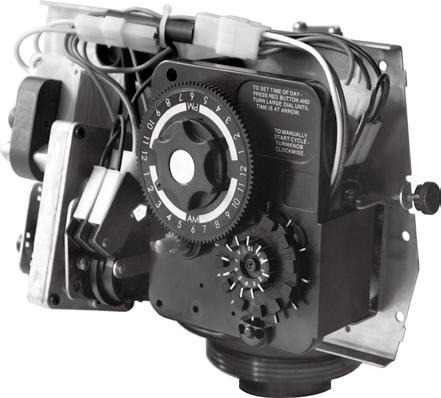
11 MODEL 00 & 0 TIMER SERIES Regeneration Cycle program Setting Procedure Even though it takes three hours for this center knob to complete one revolution, the regeneration cycle of your unit might be set for only one half of this time. Typical Programming Procedure Calculate the gallon capacity of the system, subtract the necessary reserve requirement and set the gallons required by Iifting the gallon dial and rotating it so that the number of gallons required is aligned with the white dot on program wheel gear. Release and check for firm engagement with gear. In any event, conditioned water may be drawn after rinse water stops flowing from the water conditioner drain Iine. Immediate Regeneration Timers: Note: To set meter capacity at initial start-up, either:. Rotate manual regeneration knob one full revolution. or. Rotate program wheel manually clockwise and align white dot with capacity arrow. These timers do not have a 4 hour gear. Setting the gallons on the program wheei and manual regeneration procedure are the same as previous instructions. This procedure must be followed any time the program wheel setting is changed. How To Set The Time Of Day: Press and hold the red button in to disengage the 4 hour gear. Manual Regeneration Knob 4 HR. Gear Turn the 4 hour gear until the actual time of day is at the time of day pointer. Release the red button to again engage the 4 hour gear. How To Manually Regenerate Your Water Condition At Any Time: Turn the manual regeneration knob clockwise one click. This slight movement of the manual regeneration knob engages the program wheel and starts the regeneration program. TO SET TIME OF DAYPRESS RED BUTTON AND TURN LARGE AIAL UNTIL TIME IS AT ARROW. TO MANUALLY START CYCLETURN KNOB CLOCKWISE. Service Position Indicator CAPACITE CAPACITY KAPAZITAT CAPACITA CAPACIDAD M Capacity (M Remaining) White Dot (M Capacity) Red Time Set Button The black center knob will make one revolution in the following approximately three hours and stop in the position shown in the drawing. CAUTION ALWAYS REMOVE CABLE FROM METER BEFORE SWINGING TIMER OPEN. Program Wheel Page 0 M Label
12 MODEL 00 & 0 TIMER SERIES Timer Setting Procedure Service Position Indicator How To Set Days On Which Water Conditioner Is To Regenerate: Rotate the skipper wheel until the number is at the red pointer. Set the days that regeneration is to occur by sliding tabs on the skipper wheel outward to expose trip fingers. Each tab is one day. Finger at red pointer is tonight. Moving clockwise from the red pointer, extend or retract fingers to obtain the desired regeneration schedule. Manual Regeneration Knob TO SET TIME OF DAYPRESS RED BUTTON AND TURN LARGE DIAL UNTIL TIME IS AT ARROW. TO MANUALLY START CYCLE TURN KNOB CLOCKWISE. Red Pointer How To Set The Time Of Day: Press and hold the red button in to disengage the drive gear. Turn the Iarge gear until the actual time of day is at the time of day pointer. Release the red button to again engage the drive gear. How To Manually Regenerate Your Water Conditioner At Any Time: Turn the manual regeneration knob clockwise. This slight movement of the manual regeneration knob engages the program wheel and starts the regeneration program. The black center knob will make one revolution in the following approximately three hours and stop in the position shown in the drawing. Even thought it takes three hours for this center knob to complete one revolution, the regeneration cycle of your unit might be set only one half of this time. In any event, conditioned water may be drawn after rinse water stops flowing from the water conditioner drain Iine. How to Adjust Regeneration Time:. Disconnect the power source.. Locate the three screws behind the manual regeneration knob by pushing the red button in and rotating the 4 hour dial until each screw appears in the cut out portion of the manual regeneration knob.. Loosen each screw slightly to release the pressure on the time plate from the 4 hour gear. 4. Locate the regeneration time pointer on the inside of the 4 hour dial in the cut out. 5. Turn the time plate so the desired regeneration time aligns next to the raised arrow.. Push the red button in and rotate the 4 hour dial. Tighten each of the three screws. 7. Push the red button and Iocate the pointer one more 4 HR. Gear E Y A TIMF D O Red Time Set Button Skipper Wheel, Day (Shows Every Other Day Regeneration) time to ensure the desired regeneration time is correct. 8. Reset the time of day and restore power to the unit. IMPORTANT SALT LEVEL MUST ALWAYS BE ABOVE WATER LEVEL ln BRINE TANK. Page
13 MODEL 00 & 0 TIMER SERIES Regeneration Cycle program Setting Procedure How To Set The Regeneration Cycle Program: The regeneration cycle program on your water conditioner has been factory preset, however, portions of the cycle or program may be lengthened or shortened in time to suit local conditions. 00 & 0 Series Timers (Figure to Right) To expose cycle program wheel, first pull cable out of meter dome of 0 timers, grasp timer in upper Ieft-hand corner and pull, releasing snap retainer and swinging timer to the right. To change the regeneration cycle program, the program wheel must be removed. Grasp program wheel and squeeze protruding Iugs toward center, Iift program wheel off timer. (Switch arms may require movement to facilitate removal.) Return timer to closed position engaging snap retainer in back plate. Make certain all electrical wires Iocate above snap retainer post. Reconnect meter cable. Timer Setting Procedure for 00 and 0 Timer How To Change The Length Of The Backwash Time: The programwheel as shown in the drawing is in the service position. As you Iook at the numbered side of the program wheel, the group of pins starting at zero determines the Iength of time your unit will backwash. FOR EXAMPLE: If there are six pins in this section, the time of backwash will be min. ( min. per pin). To change the Iength of backwash time, add or remove pins as required. The number of pins times two equals the backwash time in minutes. How To Change The Length Of Rapid Rinse: The second group of pins on the program wheel determines the Iength of time that your water conditioner will rapid rinse. ( min. per pin.) To change the Iength of rapid rinse time, add or remove pins at the higher numbered end of this section as required. The number of pins times two equals the rapid rinse time in minutes. How To Change The Length Of Brine Tank Refill Time: The second group of holes in the program wheel determines the length of time that your water conditioner will refill the brine tank. ( min. per hole.) To change the Iength of refill time, move the two pins at the end of the second group of holes as required. The regeneration cycle is complete when the outer microswitch is tripped by the two pin set at end of the brine tank refill section. The program wheel, however, will continue to rotate until the inner micro-switch drops into the notch on the programwheel. BACKWASH SECTION (MIN. PER PIN) PIN STORAGE PROGRAM WHEEL FOR REGENERATION CYCLE BRINE & RINSE (MIN.PER HOLE) RAPID RINSE SETION (MIN. PER PIN) How To Change The Length Of Brine And Rinse Time: The group of holes between the Iast pin in the backwash section and the second group of pins determines the Iength of time that your unit will brine and rinse ( min. per hole.) BRINE TANK To change the Iength of brine and rinse time,move the rapid rinse group of pins to give more or fewer holes in the brine and rinse section. Number of holes times two equals brine and rinse time in minutes. Page
14 Assembly Drawings and Part Numbers Medium Brining System Assembly 7 a.brine Tube(NRWB) b.brine Tube(RWB) 8 9 BLOCK-A BLOCK-C Fittings for medium (" to /") brining system BLOCK-B 0 Fittings for /" BV 7 Page 4 5
15 MODEL 00 & 0 TIMER SERIES Assembly Drawings and Part Numbers Medium Brining System Assembly Parts List Item No. Quantity Part No End Plug-Brine System Assembly O-Ring- AS RFC Washer-5.0 gpm Flow Control Retainer Piston- Brine System Assembly Piston Rod- Brine System Assembly O-Ring- AS Spacer- Brine System Assembly Brine Valve Body Insert sleeve Retainer Nut Quad Ring- ASQ Spring- Brine Valve Retaining Ring d Stem Guide Screw,ch,M5x70mm,A Injector Cover Injector Cover Gasket # Injector Nozzle # Injector Nozzle Injector Screen Injector Body # Injector Throat # Injector Throat Water Disperser Injector Body Gasket Elbow Fitting Air Check 0 Description Bold faced items are recommended spare parts. Page 4
16 Assembly Drawings and Part Numbers.5" Flow Meter Assembly Mechanical Meter Cover Assembly Electronic Meter Cover Assembly Page 5
17 Assembly Drawings and Part Numbers.5" Flow Meter Assembly Parts List Item No. Quantity Part No Meter Cable Assembly(.5 ) Screw,ch,M5x5mm,A Meter Cover Assembly Screw,tchw,NO.8-8x/8,Zn, Meter Cable Assembly(5 ) Meter Cable Assembly(99.5 ) Meter Cover Assembly O-Ring- AS Impeller Post, Impeller Meter Body(NPT) Meter Body(BSP) Flow Straightener O-Ring- AS Nipple -Quick Connect(NPT) Nipple-Quick Connect(BSP) Nut- Quick Connect Bold faced items are recommended spare parts. Page Description
18 Dimensional Drawing )F40 Valve RWB 45mm (9.7") " " 0mm (4") /" " 0mm (9.") 0mm (.") 8mm (7.") 4" UN NRWB 58mm (0.") " " 0mm (4") /" " 0mm (9.") 0mm (.") 94mm (7.") 4" UN Page 7
19 Assembly Kits )For F40 Valve Piston Kits Piston Kits-NRWB Piston Kits-RWB Adapters Fittings for medium ( to ½ brining system Fittings for / BV Seals & Spacers F40 Spacers & Seals Injector #5 Injector Assembly # Injector Assembly Meter(.5" Electronic Flow Meter) " Cable " Cable Meter(.5" Extended Mechanical Flow Meter) Medium ½ Brine Valve Brine Valve Assembly RFC Washers G RFC Housing Assembly H OO )ORZ &RQWURO ZLWK JSP washer % 5H OO )ORZ &RQWURO ZLWK JSP washer Drive Cam Assembly Drive Cam Assembly BWFC Washers G G G G G G G BWFC Housing Assembly NPT 0G BSP 0G NPT 5G Page 8 BSP 5G NPT 5G BSP 5G NPT 50G BSP 50G NPT 00G BSP 00G
20 Service Instructions PROBLEM. Softener fails to regenerate. CAUSE A. Electrical service to unit has been interrupted. B. Timer is defective. Hard water. A. Assure permanent electrical service (check fuse, plug, pull chain or switch). B. Replace timer. C. Power failure.. CORRECTION C. Reset time of day. A. By-pass valve is open. A. Close by-pass valve. B. No salt in brine tank. C. Injector screen plugged. D. Insufficient water flowing into brine tank. B. Add salt to brine tank and maintain salt Ievel above water Ievel. C. Clean injector screen. E. Hot water tank hardness. D. Check brine tank fill time and clean brine line flow control if plugged. F. Leak at distributor tube. E. Repeated flushings of the hot water tank is required. G. Internal valve Ieak. F. Make sure distributor tube is not cracked. Check O-ring and tube pilot. G. Replace seals and spacers and/or piston.. 4. Unit used too much salt. Loss of water pressure. A. Improper salt setting. A. Check salt usage and salt setting. B. Excessive water in brine tank. B. See problem no. 7 A. Iron buildup in Iine to water conditioner. A. Clean Iine to water conditioner. B. lron buildup in water conditioner. B. Clean control and add mineral cieaner to mineral bed. lncrease frequency of regeneration. C. Inlet of control plugged due to foreign material broken Ioose from pipes by recent work done on plumbing system. 5. Loss of mineral through drain Iine. A. Air in water system. B. Improperly sized drain line flow control.. Iron in conditioned water. A. Fouled mineral bed. C. Remove piston and clean control. A. Assure that well system has proper air eliminator control. Check for dry well condition. B. Check for proper drain rate. A. Check backwash, brine draw and brine tank fill. Increase frequency of regeneration. lncrease backwash time. A. Clean flow control. 7. Excessive water in brine tank. A. Plugged drain Iine flow control. B. Plugged injector system. B. Clean injector and screen. C. Replace timer. D. Replace brine vaive seat and ciean valve. C. Timer not cycling. D. Foreign material in brine valve. E. Foreign material in brine iine flow control. Page 9 E. Clean brine Iine flow control.
21 Service Instructions CAUSE PROBL EM 8. Softener fails to draw brine. A. Drain Iine fiow controi is piugged. A. Clean drain Iine flow control. B. Injector is plugged. B. Clean injector. C. Injector screen plugged. C. Clean screen. D. Line pressure is too low. F. Service adapter did not cycle. Control cycles continuously. 0. Drain flows continuously. D. lncrease Iine pressure to 0 P.S.I. E. Change seals, spacers and piston assembly. E. InternaI control Ieak. 9. CORRECTION F. Check drive motor and switches. A. Missadjusted, broken or shorted switch. A. Determine if switch or timer is faulty and replace it, or replace complete power head. A. Valve is not programing correctly. A. Check timer program and positioning of control. Replace power head assembly if not positioning properly. B. Foreign material in control. B. Remove power head assembly and inspect bore. Remove foreign material and check control in various regeneration positions. C. Replace seals and piston assembly. C. InternaI control Ieak. General Service Hints For Meter Control Problem: Softener Delivers Hard Water. Cause couid be that... Reserve Capacity Has Been Exceeded. Correction: Check salt dosage requirements and reset program wheel to provide additional reserve. Cause could be that... Program Wheel Is Not Rotating With Meter Output. Correction: Pull cable out of meter cover and rotate manually. Program wheel must move without binding and clutch must give positive clicks when program wheel strikes regeneration stop. lf it does not, repiace timer. Cause could be that... Meter Is Not Measuring Flow. Correction: Check meter with meter checker. Page 0
22 Note Page
23 Note Page
24
This unit is superb for commercial applications where soft water is required 100% of the time.
 Model 9000 water softener Rayne Infinity Water Softener This image portrays the locations the 9000 water softner unit is best suited; a car wash; laundry; motel and restaurants. This model 9000 water softener
GRANT-DILLING-HARRIS INC. WATER SOFTENER THEORY OF OPERATION
 GRANT-DILLING-HARRIS INC. WATER SOFTENER THEORY OF OPERATION WATER SOFTENER: The Water Softener requires a 120VAC 2 AMP electrical service and the Water lines in and out need to be sized to the Softener.
Plumbline 1000 Series Timered Softeners Owners Manual Water Softener Models
 Plumbline 1000 Series Timered Softeners Owners Manual Water Softener Models PS1000T PS1500T Table of Contents How to Use Soft Water 3 Product Line Overview 5 System Operation 6 System Maintenance and Install
Plumbline 2000 Series Metered Softeners Owners Manual Water Softener Models
 Plumbline 2000 Series Metered Softeners Owners Manual Water Softener Models PS2000M PS2500M PS2700M PS2900M Table of Contents How to Use Soft Water 3 Product Line Overview 5 System Operation 6 System Maintenance
541D19 SERIES. Technical Manual. A Division of Aquion Partners L.P.
 541D19 SERIES Technical Manual A Division of Aquion Partners L.P. Table of Contents Introduction... Page 1 Technical Specifications... Page 2 Flow Diagrams... Page 3 Injector & Flow Control Selection Injector...
6700 Valve Downflow. Automatic Water Softeners Operation Manual. Read all instructions carefully before operation. #51431 Rev.
 6700 Valve Downflow Automatic Water Softeners Operation Manual Read all instructions carefully before operation. #51431 Rev. 11/08 US Performance and Specifications Downflow Capacity at Various Salt Dosages
6700 Valve Upflow. Automatic Water Softeners Operation Manual. Read all instructions carefully before operation. #57341 Rev.
 6700 Valve Upflow Automatic Water Softeners Operation Manual Read all instructions carefully before operation. #57341 Rev. 11/08 US Performance and Specifications Upflow Capacity at Various Salt Dosages
Sanitizer Series. Water Conditioners
 Sanitizer Series Water Conditioners TABLE OF CONTENTS Installation Instructions..........................................3-4 Start-up Procedures.............................................5-6 Programming
Metermatic Water Softener. Operation Manual
 Metermatic Water Softener Operation Manual Page 5 of this manual contains important maintenance procedures for the continued proper operation of your unit. These MUST be performed regularly for your guarantee
Record of System Specifications 2 Product Dimensions 3 Pre-Installation Checklist 4 System Installation 5-9 Installation Notice, Unit location,
 Record of System Specifications 2 Product Dimensions 3 Pre-Installation Checklist 4 System Installation 5-9 Installation Notice, Unit location, Plumbing Setup, Control Valve Installation Instructions 5
Owner s Manual / 5600 Econominder
 5600 / 5600 Econominder Owner s Manual For questions or in case of emergency, please call your local service technician (preferably the one who installed the system). Product Features, Benefits, & Job
6700XTR Valve Downflow
 6700XTR Valve Downflow Automatic Water Softeners Operation Manual Read all instructions carefully before operation. #51545 Rev. 11/08 US Performance and Specifications Downflow Capacity at Various Salt
Water Softener Installation Guide Effective for all Softeners from our Range
 Water Softener Installation Guide Effective for all Softeners from our Range Planning Your Installation Always observe the water byelaws. Ensure there is only one rising main, that you have allowed space
HD / HDL Valves & Systems Service Manual
 Innovative Solutions for Your Water HD / HDL Valves & Systems Service Manual Hankscraft Runxin, LLC 300 Wengel Drive Reedsburg, WI 53959 608.524.9465 sales@hrh2o.com hrh2o.com 2 Table of Contents 1. Introduction...
Model NFF Iron, Manganese, Hydrogen Sulfide Reduction
 Super Filter Model NFF Iron, Manganese, Hydrogen Sulfide Reduction Operating and Maintenance Manual Page 1 of this manual contains operating conditions. 57055 9/07 Enjoy clean, stain-free laundry and dishes...
Installation and Operation Manual
 Installation and Operation Manual NOTE: RISER / DISTRIBUTOR PIPE SHOULD BE CUT 1/2 BELOW THE TOP SURFACE OF THE TANK INSERT. MTS 95 System REVISION # 3 REVISION DATE SEPTEMBER 12, 2013 2 Table of Contents
Installation Instructions and Owner s Manual. FSN Series. Nitrate Removal Water Softening System
 Installation Instructions and Owner s Manual FSN Series Nitrate Removal Water Softening System First Sales, LLC 12630 US Highway 33 N Churubusco, IN 46723 Phone (260) 693-1972 Fax (260) 693-0602 FSN Series
NovoSoft 465 Series SIM Water Softener Operation Manual
 NovoSoft 465 Series SIM Water Softener Operation Manual Note: 1. Read all instructions carefully before operation. 2. Avoid pinched o-rings during installation by applying (provided with install kit) NSF
Autotrol Performa FA Valve
 Autotrol Performa FA Valve With 400 Series Control Water Conditioning Control System Dealer Installation, Operation, and Maintenance Manual Table of Contents Installation................................
Installation Instructions and Owner s Manual. KLX2 & KLX2E Series. Catalytic Filter System
 Installation Instructions and Owner s Manual KLX2 & KLX2E Series Catalytic Filter System First Sales, LLC 12630 US Highway 33 N Churubusco, IN 46723 Phone (260) 693-1972 Fax (260) 693-0602 KLX2-KLX2E Instruction
Installation Instructions and Owner s Manual. FS, FSM, & FES Series. Water Softening System
 Installation Instructions and Owner s Manual FS, FSM, & FES Series Water Softening System MODEL NUMBERS: Time Clock Mechanical Metered FSL Series FSLM Series FS Series FSM Series High Efficiency High Efficiency
Fleck 2510 Softener Installation & Start Up Guide
 Clean Water Made Easy www.cleanwaterstore.com Fleck 2510 Softener Installation & Start Up Guide Thank you for purchasing a Clean Water System! With proper installation and a little routine maintenance
Fleck 2510 Sediment Filter Installation & Start-Up Guide
 Clean Water Made Easy www.cleanwaterstore.com Fleck 2510 Sediment Filter Installation & Start-Up Guide Thank you for purchasing a Clean Water System! With proper installation and a little routine maintenance
7000 Meter Initiated Valve
 7000 Meter Initiated Valve Water Softener Operation Manual Read all instructions carefully before operation. #51400 Rev. 2/09 Performance and Specifications Item Model Capacity at regeneration salt levels
Installation Instructions and Owner s Manual. N, NMS, NES, & INT2 Series. Water Softening Systems
 Installation Instructions and Owner s Manual N, NMS, NES, & INT2 Series Water Softening Systems MODEL NUMBERS: Time Clock Mechanical Metered NC Series NMCS Series N Series NMS Series High Efficiency High
Fully Automatic Water Filters
 INSTALLATION INSTRUCTIONS Fully Automatic Water Filters INSTALLATION INFORMATION Model No. Unit Date Code Date Installed WATER ANALYSIS RECORD Hardness GPG Sulfur PPM Iron PPM ph Manganese PPM Tannins
6700XTR Upflow Valve. Water Softener Operation Manual. Read all instructions carefully before operation. #51548 Rev. 2/09
 6700XTR Upflow Valve Water Softener Operation Manual Read all instructions carefully before operation. #51548 Rev. 2/09 Performance and Specifications Item Model Capacity at regeneration salt levels Service
Owner's Manual. WS Series. Water Softener
 Owner's Manual WS-165-150 Series Water Softener Table of Contents WHAT'S INCLUDED 3 OPERATING CONDITIONS 4 ASSEMBLY INSTRUCTIONS 6 FLUSHING THE WATER LINES 13 MASTERPROGRAMMING 14 PROGRAMMING KEYAND GENERAL
Autotrol Brand Performa Valve / 400 Series Controls
 Autotrol Brand Performa Valve / 400 Series Controls Water Conditioning Control System Home Owner Installation, Operation, and Maintenance Manual For sales or service questions please contact your local
Autotrol Performa Valve
 Autotrol Performa Valve With 400 Series Control Water Conditioning Control System Dealer Installation, Operation and Maintenance Manual Table of Contents Installation................................ Location
Clean Water Made Easy. CWS Time Clock Softener Installation & Start Up Guide. Questions?
 Clean Water Made Easy www.cleanwaterstore.com CWS Time Clock Softener Installation & Start Up Guide Thank you for purchasing a Clean Water System! With proper installation and a little routine maintenance
Econoflo SXT Automatic Meter Initiated Water Softener
 Econoflo SXT Automatic Meter Initiated Water Softener Operating and Maintenance Manual Page 5 of this manual contains important maintenance procedures for the continued proper operation of your unit. These
Autotrol Brand 255 Valve / 400 Series Controls
 Autotrol Brand 255 Valve / 400 Series Controls Water Conditioning Control System Home Owner Installation, Operation, and Maintenance Manual For sales or service questions please contact your local dealer:
ProFlo SXT Valve Downflow / Upflow
 ProFlo SXT Valve Downflow / Upflow Automatic Water Softeners Operation Manual Read all instructions carefully before operation. #54719 Rev. 1/09 US Performance and Specifications Downflow Upflow Capacity
Autotrol Performa Valve
 Autotrol Performa Valve With 400 Series Control Water Conditioning Control System Dealer Installation, Operation and Maintenance Manual Table of Contents Installation................................ Location
Model 7000SXT. Service Manual. IMPORTANT: Fill in Pertinent Information on Page 3 for Future Reference
 Model 7000SXT Service Manual IMPORTANT: Fill in Pertinent Information on Page 3 for Future Reference Table of Contents Job Specification Sheet... 3 Installation Instructions... 4 Start-Up Instructions...
1850 Series TRIPLE TREAT Operation Manual
 1850 Series TRIPLE TREAT Operation Manual BRINE TANK RESIN TANK CARBON TANK System shown with optional tank jackets. Note: 1. Read all instructions carefully before operation. 2. Avoid pinched o-rings
Installation Instructions and Owner s Manual. OXY3 & OXY3E Series. Iron Reduction System
 Installation Instructions and Owner s Manual OXY3 & OXY3E Series Iron Reduction System First Sales, LLC 12630 US Highway 33 N Churubusco, IN 46723 Phone (260) 693-1972 Fax (260) 693-0602 OXY3-OXY3E Instruction
FLECK 3200 SERIES ELECTROMECHANICAL TIMER OWNER S MANUAL
 FLECK 3200 SERIES ELECTROMECHANICAL TIMER OWNER S MANUAL waterpurification.pentair.com FEATURES OF YOUR WATER CONDITIONING SYSTEM Congratulations on the purchase of your new water treatment system featuring
Model 7000SXT. Service Manual. IMPORTANT: Fill in Pertinent Information on Page 3 for Future Reference
 Model 7000SXT Service Manual IMPORTANT: Fill in Pertinent Information on Page 3 for Future Reference Table of Contents Job Specification Sheet... 3 Installation Instructions... 4 Start-Up Instructions...
High Flow 7000 SXT Water Softener
 High Flow 7000 SXT Water Softener Operating and Maintenance Manual WQA Tested and Certified against CSA B483.1 Read all instructions carefully before operation. #54736WQA 3/11 ii Performance Data Sheet
Autotrol 255 Valve / 400 Series Controls
 Autotrol 255 Valve / 400 Series Controls Water Conditioning Control System Home Owner Installation, Operation and Maintenance Manual For sales or service questions please contact your local dealer: Your
Installation Instructions and Owner s Manual. O3 & O3E Series. Iron Reduction System
 Installation Instructions and Owner s Manual O3 & O3E Series Iron Reduction System First Sales, LLC 12630 US Highway 33 N Churubusco, IN 46723 Phone (260) 693-1972 Fax (260) 693-0602 O3-O3E Instruction
High Flow 7000 SXT Series Water Softeners
 High Flow 7000 SXT Series Water Softeners Operating and Maintenance Manual Read all instructions carefully before operation. #54736 12/08 Performance and Specifications Model Capacity - Grains Flow Rates
TITAN VI High Efficiency Water Conditioner Installation and Operation Manual
 TITAN VI High Efficiency Water Conditioner Installation and Operation Manual Manufacturer s Warranty Holts Water Conditioning 369 South Mountainway Drive Orem, UT 84058 801-426-9243 To the original purchaser,
TITAN Pro-Max High Efficiency Upflow Water Conditioner Installation and Operation Manual
 TITAN Pro-Max High Efficiency Upflow Water Conditioner Installation and Operation Manual TITAN VI Pro-Max Manufacturer s Warranty Holts Water Conditioning 369 South Mountainway Drive Orem, UT 84058 801-426-9243
Spectrum TM. Installation, Service & Operation Manual O FLO. SoftH 2. Water Softener. Table of Contents
 Installation, Service & Operation Manual SoftH 2 O FLO Water Softener Table of Contents 1. Description & Equipment Adjustments p.2 2. Components, Features & Functions p.3 3. Valve User Interface p.4 4.
FULLY AUTOMATIC WATER SOFTENER
 OWNERS GUIDE TO INSTALLATION AND OPERATION Section: 6.10.130 FM2035 0302 Supersedes 0102 FULLY AUTOMATIC WATER SOFTENER MODEL 340 SAFETY INFORMATION Read the instructions carefully and learn the specific
Autotrol Performa Valve with 400 Series Control Water Conditioning Control System
 Autotrol Performa Valve with 400 Series Control Water Conditioning Control System Service Manual 460TC BRINE/ SLOW RINSE DAYS CLOCK BACKWASH FAST RINSE/ REFILL CONDITIONED WATER MANUAL REGENERATION: PRESS
Series 255 Valve / 460i. Water Conditioning Control System Installation, Operation and Maintenance Manual
 Series 255 Valve / 460i Water Conditioning Control System Installation, Operation and Maintenance Manual Table of Contents Introduction............................... 2 Series 255/460i Demand Control System
Green Water Systems OWNERS MANUAL. Includes: Installation Procedures, Warranties, Service & Operation Guidelines.
 Green Water Systems OWNERS MANUAL Includes: Installation Procedures, Warranties, Service & Operation Guidelines. GS Elite GS PRO GS1 1 Cu. Ft. S. C. S. GS1.5 1 Cu. Ft. S. C. S. GS2 2 Cu. Ft. S. C. S. 7000
AUTOMATIC CARBON FILTER INSTALLATION & OPERATING INSTRUCTIONS
 AUTOMATIC CARBON FILTER INSTALLATION & OPERATING INSTRUCTIONS Model: AFC09-263 Serial No: Manufacturer and Supplier of FILTRATION & WATER TREATMENT PRODUCTS for commercial, industrial and residential application
Installation, Operation and Maintenance Manual. Infusion Residential Water Softener 169-ISF-1C 169-ISF-2C 169-ISF-3C 169-ISF-4C
 Installation, Operation and Maintenance Manual Infusion Residential Water Softener Calcium, magnesium removal system 169-ISF-1C 169-ISF-2C 169-ISF-3C 169-ISF-4C US Water Systems, Inc. 1209 Country Club
This material is intended only for Glass Water Systems customers. Reproduction or distribution of this material is strictly prohibited and protected.
 This material is intended only for Glass Water Systems customers. Reproduction or distribution of this material is strictly prohibited and protected. For further questions contact Glass Water Systems or
CMP & C METERED SERIES
 INSTALLATION, OPERATION, AND MAINTENANCE MANUAL CMP & C METERED SERIES RESIDENTIAL WATER CONDITIONER COMPLETE FOR FUTURE REFERENCE: MODEL NO: SERIAL NO: DATE INSTALLED: DEALER: Marlo Incorporated 2227
Installation, Operation, and Maintenance Manual. Waterlogix Metered Residential Water Softener
 Installation, Operation, and Maintenance Manual Waterlogix Metered Residential Water Softener Waterlogix WLS-075 Waterlogix WLS-075C Waterlogix WLS-100 Waterlogix WLS-100C Waterlogix WLS-150 Waterlogix
MP-MBA-45T-1/60T-1 / 75T-1
 MASTER Water Conditioning Corp. www.masterwater.com Installation and Operation Manual MP-MBA-45T-1/60T-1 / 75T-1 with the 268/762 Logix Control Valve July 2006 Table of Contents Page No. Topic Description
MASTER. Water Conditioning Corp. MP-TS-10T/20T with the 255/762 Logix Control Valve With Vortech. Installation and Operation Manual
 MASTER Water Conditioning Corp. www.masterwater.com Installation and Operation Manual MP-TS-10T/20T with the 255/762 Logix Control Valve With Vortech February 2010 Table of Contents Page No. Topic Description
5900S Softener Installation & Start-Up Guide
 Clean Water Made Easy www.cleanwaterstore.com 5900S Softener Installation & Start-Up Guide Thank you for purchasing a Clean Water System! With proper installation and a little routine maintenance your
Installation and Operation Manual
 Installation and Operation Manual 95 BIF / BAF Filter Manual NOTE: 1.5 RISER / DISTRIBUTOR PIPE SHOULD BE CUT 1/2 BELOW THE TOP SURFACE OF THE TANK INSERT. 1. Read all instructions carefully before operation.
Installation Instructions and Owner s Manual. FBW, FEBW, FBW-ARSENIC & FEBW-ARSENIC Series. Backwashing Filter Systems
 Installation Instructions and Owner s Manual FBW, FEBW, FBW-ARSENIC & FEBW-ARSENIC Series Backwashing Filter Systems First Sales, LLC 12630 US Highway 33 N Churubusco, IN 46723 Phone (260) 693-1972 Fax
Water Softener & Single Tank Triple Treat System Installation Overview. Using 1850 Metered Valves
 Water Softener & Single Tank Triple Treat System Installation Overview Using 1850 Metered Valves System Installation CAUTION: Do not use systems on untreated well water that is microbiologically unsafe.
Fully Automatic Water Softeners
 OWNERS GUIDE TO INSTALLATION AND OPERATION Fully Automatic Water Softeners SINGLE TANK CABINET MODELS TWO TANK MODELS Read the instructions carefully and learn the specific details regarding installation
765 Valve Filters (Taste & Odor, Nextsand, Multimedia, Neutralizer)
") 765 Valve Filters (Taste & Odor, Nextsand, Multimedia, Neutralizer) Owners Manual FOLLOWTHE INSTALLATION INSTRUCTIONS CAREFULLY. FAILURE TO INSTALL THE UNIT PROPERLY VOIDS THE WARRANTY. BEFORE YOU BEGIN
765 Valve Filters (Taste & Odor, Nextsand, Multimedia, Neutralizer) Owners Manual FOLLOWTHE INSTALLATION INSTRUCTIONS CAREFULLY. FAILURE TO INSTALL THE UNIT PROPERLY VOIDS THE WARRANTY. BEFORE YOU BEGIN
FUSION PROFESSIONAL-GRADE METERED NITRATE REMOVAL SYSTEM
 Visit us online at www.uswatersystems.com FUSION PROFESSIONAL-GRADE METERED NITRATE REMOVAL SYSTEM Owners Manual Models: 086-FNLT-XXX-NT REVISION # 1.0 REVISION DATE : September 18, 2018 US Water Systems
Econoflo Water Conditioner. Installation and Maintenance Instruction Manual
 Econoflo Water Conditioner Installation and Maintenance Instruction Manual Tested and Certified by the Water Quality Association to CSA B483.1. Owners Manual FOLLOWTHE INSTALLATION INSTRUCTIONS CAREFULLY.
What to expect from your water softener
 What to expect from your water softener All water softeners work on the same basic principal. Hard water flows through a bed of resin and the calcium and magnesium, the minerals that are responsible for
EVOLIO-560 Water Softener System
 EVOLIO-560 Water Softener System Operations manual IT FR DE ES MODELS: EVOLIO-560 8 - EVOLIO-560 15 - EVOLIO-560 20 - EVOLIO-560 30 EVOLIO-560 Demand Water Softener Installation and Operating Instructions
Commercial Water Softener
 Commercial Water Softener Owners Manual 1. Read all instructions carefully before operation. 2. Avoid pinched o-rings during installation by applying (provided with install kit) NSF certified lubricant
765 IS Greensand Filter. Proud member of Canadian Institute of Plumbing & Heating. Proud member of Canadian Water Quality Association.
 765 IS Greensand Filter Proud member of Canadian Institute of Plumbing & Heating. Owners Manual Proud member of Canadian Water Quality Association. 1. Read all instructions carefully before operation.
Installation & Service Manual
 Installation & Service Manual Table of Contents Unpacking & Inspection... 2 Basic Guidelines... 2 Specifications... 3 Before Starting Installation Where to install the filter... 4 Tools, pipe, fittings
Service Manual TABLE OF CONTENTS JOB SPECIFICATION SHEET EQUIPMENT CONFIGURATION WATER(9283) waterinc.com
 waterinc.com") Service Manual TABLE OF CONTENTS JOB SPECIFICATION SHEET...1 EQUIPMENT CONFIGURATION...1 SAFETY INFORMATION...2 HOW TO USE THIS MANUAL...2 GENERAL AND COMMERCIAL INSTALLATION INSTRUCTIONS...2 CONTROLLER
Service Manual TABLE OF CONTENTS JOB SPECIFICATION SHEET...1 EQUIPMENT CONFIGURATION...1 SAFETY INFORMATION...2 HOW TO USE THIS MANUAL...2 GENERAL AND COMMERCIAL INSTALLATION INSTRUCTIONS...2 CONTROLLER
SERVICE MANUAL. Bradford White ElectriFLEX HD (Heavy Duty) Commercial Electric Water Heater CEHD SERIES Immersion Thermostat Models
 Commercial Electric Water Heater CEHD SERIES Immersion Thermostat Models") Bradford White ElectriFLEX HD (Heavy Duty) Commercial Electric Water Heater CEHD SERIES Immersion Thermostat Models SERVICE MANUAL Troubleshooting Guide and Instructions for Service (To be performed ONLY
Bradford White ElectriFLEX HD (Heavy Duty) Commercial Electric Water Heater CEHD SERIES Immersion Thermostat Models SERVICE MANUAL Troubleshooting Guide and Instructions for Service (To be performed ONLY
IMPORTANT SAFETY INFORMATION READ ALL...
 INSTALLATION and SERVICE MANUAL HOUSEPURE MODELS HP03 and HP04 736-0137 Table of Contents IMPORTANT SAFETY INFORMATION READ ALL... 3 P/N 41482 Rev A 06/04 INSTRUCTIONS BEFORE USING... 3 FEEDWATER... 4
model NO. LSS GALLON SKID MOUNTED HIGH PRESSURE SPRAYER ASSEMBLY / OPERATION INSTRUCTIONS / PARTS
 000 model NO. LSS- 00 GALLON SKID MOUNTED HIGH PRESSURE SPRAYER ASSEMBLY / OPERATION INSTRUCTIONS / PARTS Part number and descriptions can be obtained from the illustrated parts list section of this manual.
565IS Greensand Filter. Proud member of Canadian Institute of Plumbing & Heating. Proud member of Canadian Water Quality Association.
 565IS Greensand Filter Proud member of Canadian Institute of Plumbing & Heating. Owners Manual Proud member of Canadian Water Quality Association. 1. Read all instructions carefully before operation. 2.
Installation Instructions & Operating Manual. EM Series. Water Softener System
 Installation Instructions & Operating Manual EM Series Water Softener System First Sales, LLC 1630 US Highway 33 N Churubusco, IN 4673 Phone (60) 693-197 Fax (60) 693-060 EM Installation Manual 170818.docx
Care and Use Manual Tank Series Appliances
 Care and Use Manual Tank Series Appliances 4.4-1 Information Provided for the Proper Set-Up, Installation and Start-Up of the following Appliances: EWS Series of Whole Home Filtration and Physical Conditioning:
Installation and Operations Guide
 Installation and Operations Guide Elite Series Model: 1620 S & E LifeSource Water Systems, Inc. 523 S. Fair Oaks Ave. Pasadena, CA 91105 LifeSourceWater.com Customer Service: (626) 792-9996 CA Lic. #787179
Autotrol Performa Ultra. Electronic Control System Operation and Maintenance Manual
 Autotrol Performa Ultra Electronic Control System Operation and Maintenance Manual Table of Contents Performa Ultra........................... 3 Electronic Demand System................. 3 Special Features
RevV4 Valves & Systems Service Manual. Innovative Solutions for Your Water
 Innovative Solutions for Your Water RevV4 Valves & Systems Service Manual Hankscraft Runxin, LLC 300 Wengel Drive Reedsburg, WI 53959 608.524.9465 sales@hrh2o.com hrh2o.com 2 Table of Contents 1. Introduction...
565 TLC Softener & Tannins Reduction System
 565 TLC Softener & Tannins Reduction System Owners Manual 1. Read all instructions carefully before operation. 2. Avoid pinched o-rings during installation by applying (provided with install kit) NSF certified
Owner s Manual. 12 Volt Electronics. AMERICAN AQUA Saline, MI (734) Howell, MI (517) Adrian, MI (517)
 Howell, MI (517) Adrian, MI (517)") 12 Volt Electronics Owner s Manual 2001-2009 AMERICAN AQUA Saline, MI (734)429-5070 Howell, MI (517)546-1750 Adrian, MI (517)265-8000 www.americanaqua.com This owner s manual is designed to assist owners
12 Volt Electronics Owner s Manual 2001-2009 AMERICAN AQUA Saline, MI (734)429-5070 Howell, MI (517)546-1750 Adrian, MI (517)265-8000 www.americanaqua.com This owner s manual is designed to assist owners
O P E R A T I N G M A N U A L
 GB/UK O P E R A T I N G M A N U A L Water softening device GAHOtech soft MC-N 16 109850 As of: January 2010 Location of installation Please read the operating manual before startup! The manufacturer is
RIVERSOFT Water Softener System
 RIVERSOFT Water Softener System Operations manual MODELS: RIVERSOFT 4 - RIVERSOFT 8 - RIVERSOFT 16 - RIVERSOFT 30 RiverSoft Demand Water Softener Installation and Operating Instructions TABLE OF CONTTS
E 3. Owner s Manual. Manufactured by: HELLENBRAND, INC. Phone: Fax Web:
 E 3 Owner s Manual Manufactured by: HELLENBRAND, INC. Phone: 608-849-3050 Fax 608-849-7398 Web: www.hellenbrand.com Email: info@hellenbrand.com 2011 This owner s manual is designed to assist owners and
Tier1 Water Home Filtration System
 Tier1 Water Home Filtration System Carbon+KDF Series OWNERS MANUAL BEFORE YOU BEGIN INSTALLATION, READ THIS ENTIRE MANUAL. FOLLOW THE INSTALLATION INSTRUCTIONS CAREFULLY. 1. Avoid pinched o-rings during
785 Upflow Water Softener
 Owners Manual 785 Upflow Water Softener WQA Tested and Certified according to NSF/ANSI 44 for effective reduction of hardness (calcium and magnesium) as verified and substantiated by test data. Tested
565 HIM Softener, Iron & Manganese Reduction System
 565 HIM Softener, Iron & Manganese Reduction System Owners Manual 1. Read all instructions carefully before operation. 2. Avoid pinched o-rings during installation by applying (provided with install kit)
FLECK 5600 WATER SOFTENER INSTALLATION
 FLECK 5600 WATER SOFTENER INSTALLATION Discount Water Softeners recommends using a licensed plumber to install your water softener. The following installation instructions are for use with the water softener
785 HIM Softener, Iron & Manganese Reduction System
 785 HIM Softener, Iron & Manganese Reduction System Owners Manual 1. Read all instructions carefully before operation. 2. Avoid pinched o-rings during installation by applying (provided with install kit)
485SIM Softener, Iron & Manganese Reduction System. Proud member of Canadian Institute of Plumbing & Heating.
 Owners Manual 485SIM Softener, Iron & Manganese Reduction System Proud member of Canadian Institute of Plumbing & Heating. Proud member of Canadian Water Quality Association. 1. Read all instructions carefully
FIREPLACE INSTALLATION
 CHECK GAS TYPE Use proper gas type for the fireplace unit you are installing. If you have conflicting gas types, do not install fireplace. See retailer where you purchased the fireplace for proper fireplace
Installation Instructions and Owner s Manual. CITY Series Water Softening and Filter System
 Installation Instructions and Owner s Manual CITY Series Water Softening and Filter System First Sales, LLC 12630 US Highway 33 N Churubusco, IN 46723 Phone (260) 693-1972 Fax (260) 693-0602 CITY Series
Page 1 of 18. Part# /5/2013
 Part# 1002655-06 8/5/2013 This manual contains important information concerning the installation and operation of the gun washers listed above. Read manual thoroughly and keep for future reference INSTRUCTIONS
85 TA 1 High Efficiency Twin Alternating Water Softener
 Owners Manual 85 TA 1 High Efficiency Twin Alternating Water Softener 1. Read all instructions carefully before operation. 2. Avoid pinched o-rings during installation by applying (provided with install
Technical Data. Name: ERIKA Automat fully automatic machine to divide and to round dough pieces of the same size
 AUTOMAT MANUAL 1 Technical Data Name: ERIKA Automat fully automatic machine to divide and to round dough pieces of the same size Type Divisions Dough Portions (in ounces) Plate Nos. 3 30 1.0 3.5 #35 4/40A
WASHER/DRYER CONTROL PANEL PARTS
 WASHER/DRYER CONTROL PANEL PARTS WASHER/DRYER LAUNDRY SYSTEM 1 Literature Parts W10356098 Installation Instructions W10343071 Guide, Use & Care W10364010 Wiring Diagram W10343084 Energy Guide 2 3390688
US Water Ultimate Dual Tank Superfilter
 US Water Ultimate Dual Tank Superfilter Owners Manual 1. Read all instructions carefully before operation. 2. Avoid pinched o-rings during installation by applying (provided with install kit) NSF certified
Model UVGMD-AL MULTIVERSA CAN PACKAGING MACHINE Operators Manual
 Model UVGMD-AL MULTIVERSA CAN PACKAGING MACHINE Operators Manual MODEL UVGMD-AL INTRODUCTION Model UVGMD-AL offers your choice of atmospheric, vacuum only, vacuum then gas, or multiflush double seaming.