SYSTEM MANUAL Description
|
|
|
- Magdalen Moore
- 5 years ago
- Views:
Transcription


1 SYSTEM MANUAL Description PUCK is a revolutionary fire suppression system offering discrete protection coupled with industry leading pricing, efficient system design and easy install. PUCK s lightweight nozzles sit just 3mm below the ceiling making them non-intrusive whilst offering complete protection. These nozzles connect to a compact pump unit using flexible pipework and easyfit fittings. This keeps design and install time to an absolute minimum and allows for potentially large install savings. The PUCK pump unit includes a self-test facility which is adjustable in the companion app. The app monitors the unit in real time whilst receiving alerts on faults and activations. PUCK is compatible with all fire panels offering fire and fault n/o and n/c contacts. Rev by Puck Fire Ltd
2 Advantages Industry leading pricing Low profile nozzles (colour matching available) Compact pump unit Low flow system, mains supplied, does not require large water storage tank Push fit fittings, allows for easy system install Flexible pipework, pipework can be easily measured and cut on site minimising design time Customisable self-test facility Compatible with fire panels using voltage free contacts Wireless monitoring Stainless steel pipework available where system is not installed behind fire rated barrier Certifications PUCK is 3 rd party fire tested to BS:8458 for use up to 80m 2 PUCK is 3 rd party fire tested BS:9252 Requirements PUCK s flexible pipework must be installed behind fire rated barrier Only PUCK supplied products to be used to ensure system performs as marketed Connected water source must supply no less than 12 litres per minute Pump unit must not be installed in sealed area, ventilation required.


3 TECHNICAL DATA Technical Data Pump Unit Part No: Dimensions: Voltage rating: Current rating: Fire relay contact rating: Fault relay contact rating: Inlet connection: Outlet connection: Water requirement: LED status colours: PU_ mm x 280mm x 268mm 240V 13A 30VDC, 1A max 30VDC, 1A max ½ BSP ¼ BSP 12 lpm - 1 bar Minimum Blue - Primed Orange - Wi-Fi connection fault Red - Activation


")
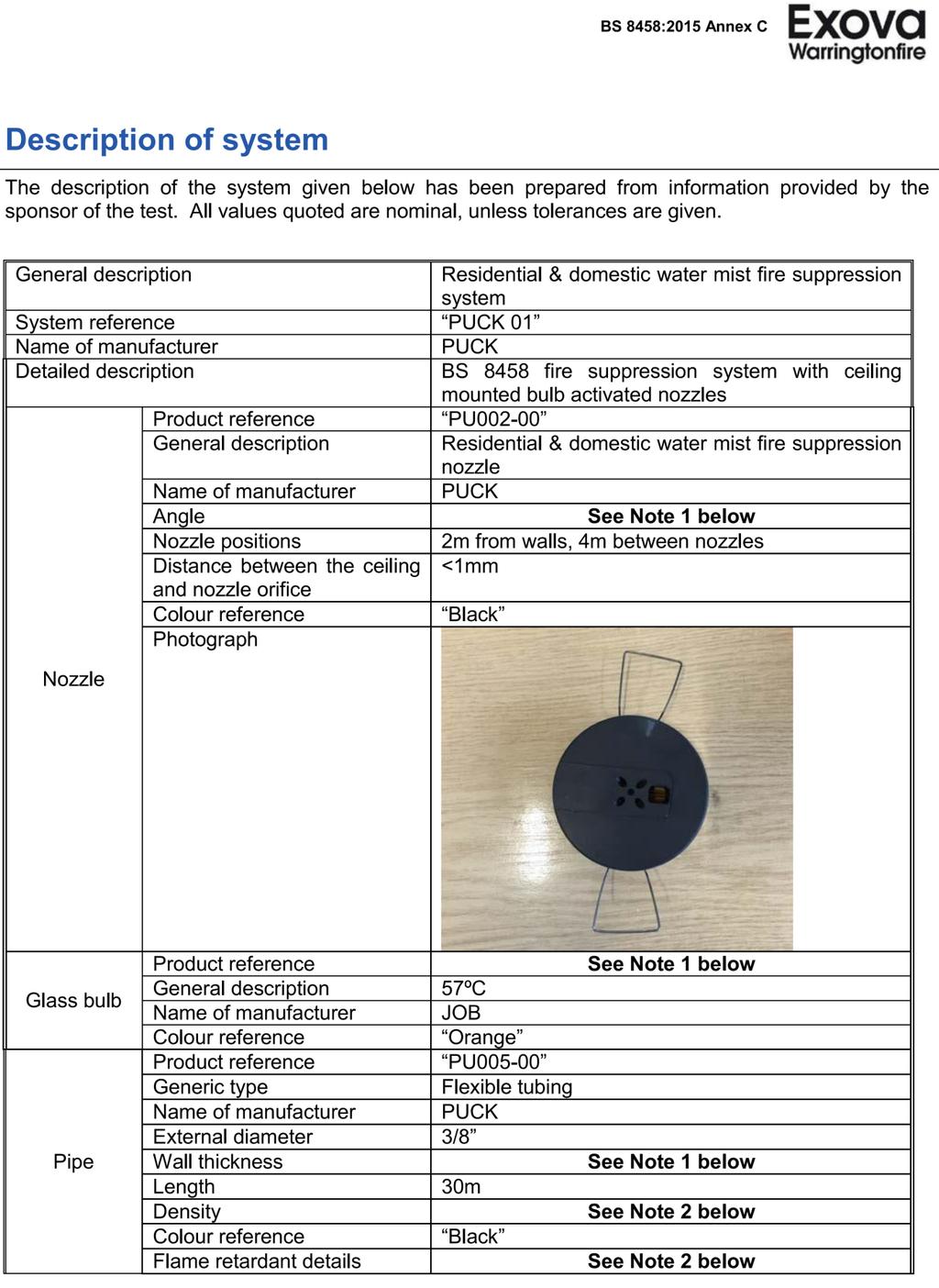
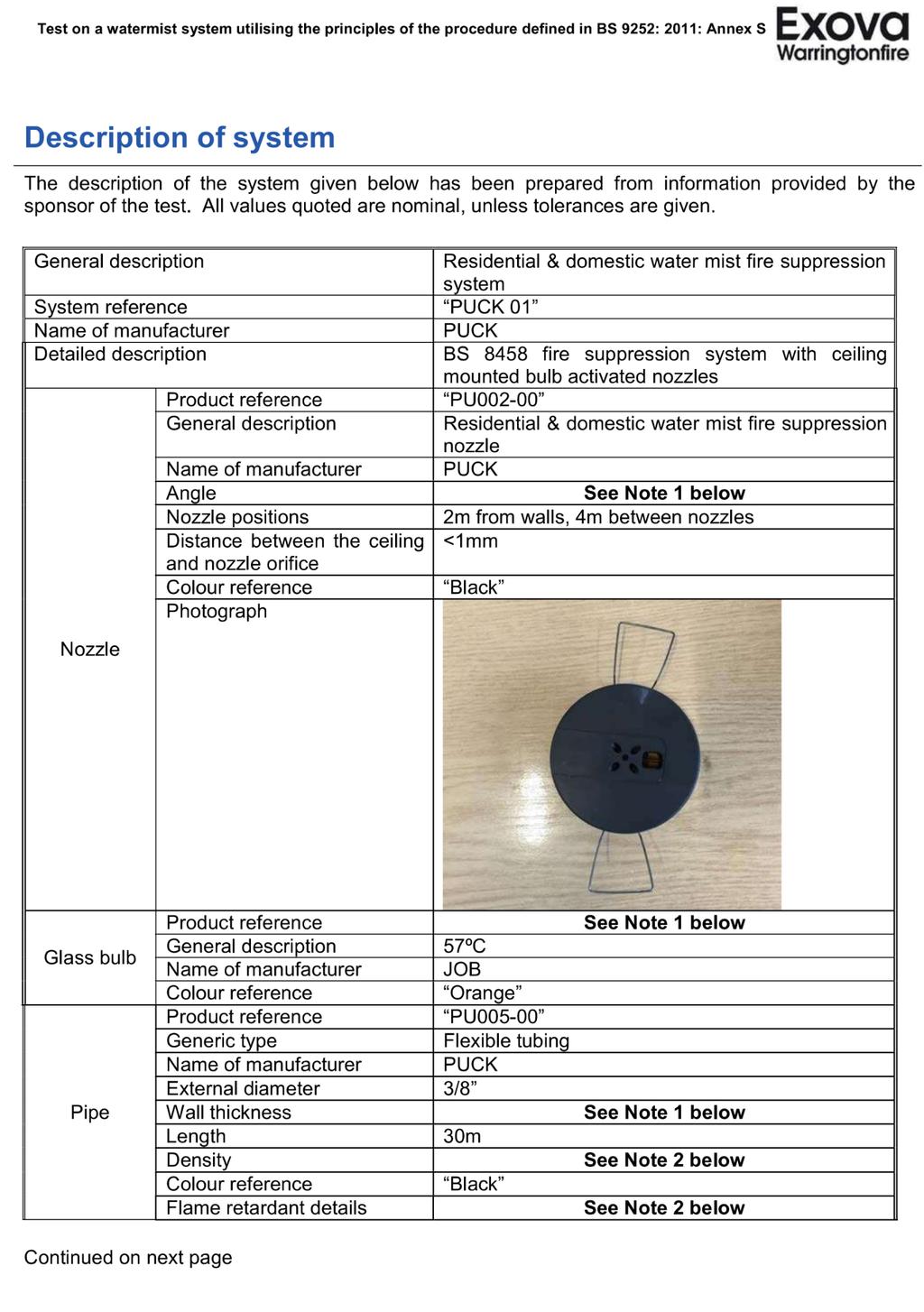
4 Nozzle Part No: Dimensions: Weight: Standard Colour: Bulb specification: Fixing method: Hole diameter for install: PU_ mm x 19mm 48g White 57 C, quick response Torsion springs 56-60mm Flexible Pipework - 30m coil Part No: Dimensions: Colour: Bend Radius: Max pipework length: Fixing method: PU_ mm, 30m reels (longer on request) Red 40mm Straight run reach - 20m Loop reach - 30m (60m total pipework) P-clips

5 Stainless Steel Rigid Pipework Part No: Dimensions: Material: Finish: Max pipework length: Fixing method: PU /8, 3m lengths Stainless steel Metallic TBC 8mm munsen ring


6 Compression Fittings Part No: Fixing type: Material: Finish: Works with: PU Tee PU Elbow PU Threaded adapter PU Straight Compression Brass Nickel Plated PUCK Flexible pipework PUCK stainless steel rigid pipework Inlet Manifold Part No: Inlet connection: Outlet connection: Approvals: PU mm compression fitting ½ BSP (to pump) WRAS approved ¼ Isolation Valve Part No: Inlet connection: Outlet connection: Material: PU-0043 ¼ BSP ¼ BSP Stainless steel


7 Self-Centring Bonded Seal Part No: Material: Seal type: Diameter: PU-0037 Zinc plated steel Nitrile ¼ BSP P-Clip Part No: Material: Diameter: PU-0040 Galvanised steel, Rubber 12mm Pressure Relief Valve Part No: Material: Diameter: Function: PU-0054 Brass 1/4-1/8 BSP Prevents system over pressurisation ¼ BSP CAP Part No: Material: Diameter: Function: PU-045 Brass Nickel Plated 1/4 - BSP End cap

8 1/2 Strainer Part No: Material: Diameter: Function: PU-042 Brass 1/2 - BSP Water Filtration WARNING: ONLY PUCK APPROVED COMPONENTS MAY BE USED WITH THIS SYSTEM. NO COMPONENT OF THE PUCK SYSTEM MAY BE MODIFIED. DOING SO WILL VOID THE COMPONENTS/SYSTEMS WARRANTY
9 SYSTEM DESIGN This manual contains manufacturers recommendations for the design, installation and commissioning of the PUCK fire and suppression system. This manual should be read in conjunction with the following standards as applicable: BS 8458 BS 9251 BS 9252 BS 7671 (Other standards may apply) Category of System The designer should at an early stage determine which category of system is applicable, as this affects various design considerations, such as the water requirements for the system. The category of system should be determined by the type of building as shown below. Domestic occupancy Single family dwellings such as: Individual dwelling house Individual flat Individual maisonette Transportable home Houses of multiple occupation (HMOs) A) Bed and breakfast accommodation A) Boarding houses A) Blocks of flats 18 m or less in height and with a maximum total floor area of m2 B), C) Residential occupancy Blocks of flats greater than 18 m in height C) Sheltered and extra care housing Residential care premises Residential rehabilitation accommodation Dormitories (e.g. attached to educational establishments) Hostels A) Buildings with more than two floors and five or more lettable bedrooms should be treated as a residential occupancy. B) Where the fire strategy requires the communal rooms and corridors to be protected by a watermist system, then the building should be treated as a residential occupancy.
10 C) This height is the height of the floor of the top storey above ground. Water Supplies Our recommendation is to install 1 pump for domestic occupancies and a dual pump system for residential occupancies. Where the mains water supply connection serves only the watermist system, the flow rates at each pump must be 12lpm. Where the mains water supply connection serves both the watermist system and the domestic or residential occupancy supply, the watermist system should be capable of providing the water demand at the pump/s by: a) the operation of an automatic priority demand valve; or b) for domestic occupancies, the flow rate at the pump plus at least 25 L/min; or NOTE 1 Attention is drawn to the water regulations, which might require a greater minimum flow rate. c) for residential occupancies, the flow rate at the pump plus at least 50 L/min. NOTE 2 Attention is drawn to the water regulations which might require a greater minimum flow rate depending on the design demand for the occupancy Flows should be tested and verified at the main water supply pipe to the property

11 Nozzle Spacing, Flat Ceilings 4x4m Grid (16M2) Max 2m from wall Minimum distance between nozzles =2m Nozzle Spacing, Sloped Ceilings- Where nozzles are fitted within a sloping ceilings, nozzle positions should be determined by the pitch of the ceiling. Where the pitch is below 30, nozzles should be mounted at standard spacing s when measured in line with the pitch of the ceiling. Where the pitch is 30 and above, the first row of nozzles should be mounted within 300 mm radially from the apex of the ceiling. All nozzles should be mounted perpendicular to the ceiling as shown below
12 Distance from Obstructions Nozzles should be positioned away from obstructions to allow a 140 degree spray pattern. Nozzle orientation

13 The preferred nozzle outlet orientation is perpendicular to the walls Maximum Pipe Lengths Pipe work should be configured as a loop not exceeding 60m in total length. Maximum 40 nozzles per loop. Loop length must be reduced by 1m for every tee or elbow added on the loop. Pipe length from the tee to the nozzle can be up to 1m long with one elbow without reducing the loop length.
14 Multi Loop Configuration example Pipework Flexible tubing should only be used behind a fire rated barrier Stainless steel tubing should be used for any areas where pipework is exposed. Nozzles for exposed pipework should not be positioned more than 300mm below the slab
15 The image below shows example piping networks for domestic and residential. Domestic Residential Pump 1 Pump 2


16 INSTALLATION & COMMISSIONING WARNING Mains voltage electricity and high pressure water are present within this product. Care should be taken when installing the product. Installation should only be carried out by trained engineers. Appropriate PPE should be worn at all times when installing the product. Eye protection, gloves, safety boots and hard hat. 1. Remove all packaging from the components provided. 2. Install a 240v, 13A un-switched spur next to the proposed pump position.
. 4.")


17 3. Connect strainer, inlet manifold and flexible hose to the mains water (ensure mains water is switched off before breaking into the water supply). 4. Verify the water supply flow by running it into a bucket to confirm the correct flow 5. Ensure the isolation valve in the inlet manifold is set to the closed position. 6. If provided with a monitoring system make connections to fire and fault relays as required. Access can be gained to the electronics by removing the screws on the lid on the underside of the pump.


18 WARNING The pump unit must be completely powered down before opening the electronics enclosure Fire & fault connections 7. Refit lid to the electronics and position the pump it it s final location. The pump must be situated in a well ventilated area with no less that 100mm of free space around all sides of the unit. The top of the pump unit must stay clear of any objects to allow for proper airflow and performance. The pump must be located in a position above 4 C. 8. Connect power cable to un-switched spur ensuring that the power remains switched off at all times. Do not run the pump without water running through it. This will damage the pumps. 9. Use the threaded end of the inlet Manifold to connect directly to the threaded fitting on the bottom section of the pump. Warning! This fitting should only need to be hand tight if this does not create a seal tighten very slightly with a spanner until a seal is created. Overtightening will damage the components.


19 10. Install pressure relief arrangement to the top of the pump ensuring it is correctly orientated and connect the drain from the pressure relief manifold to the waste pipe. Do not adjust the pre-set pressure relief valve TO SYSTEM PIPEWORK AND NOZZLES CONNECT TO DRAIN 11. Install pipework to the system using flexible pipework push fit fittings and supporting P-clips. All flexible pipework should be installed behind a fire rated barrier such as plaster board, any


20 exposed pipe should be installed in steel pipework. Pipework must never be exposed to temperatures below 4 C. 12. Cut the pipework to length using pipe cutters ensuring a square edge is achieved with the cut. CORRECT INCORRECT X 13. Easyfit fittings Insert pipe into fitting until it will not go any further. Tighten nut by using two spanners. One spanner to tighten the nut and one spanner to hold the body of the fitting Example of ferrules correctly seated on pipe work


21 14. Pushfit - Apply silicone lubricant to the end of the pipework. Insert the pipe into the fitting pushing hard to ensure that the pipe is inserted by 25mmmm. Ensure pipe is straight and is not being pulled to one side as this may create leaks CORRECT INCORRECT X WARINING Pipework and fittings must not be installed in temperatures lower than 5 C as this can affect the ability of the pushfit to grip onto the pipework and create the required seal. 15. Use a 57-64mm hole saw to create the holes in the ceiling for fitting the nozzles. 16. Install nozzles ensuring that the 1/4 adaptor with a bonded seal is tightened with a spanner. Ensure bonded seal is used. Thread lock may be used if required. DO NOT USE PTFE OR ANY OTHER TYPE OF THREAD TAPE 17. Ensuring that the pipe network is complete open isolation valve on the inlet manifold to allow mains pressure water into the system.


22 18. Slowly loosen the nozzle furthest away from the pump set to bleed the pipework of any trapped air. Allow any excess water to drain into a bucket. When all of the air has escaped remake the seal. Most remote nozzle Max pipe length before tee 800mm 19. After ensuring that there are no initial leaks power up the pump to charge the system. 20. Leave to stand at system pressure for 1 hour. The pipe work will stretch over time causing some initial loss in pressure however it will settle to around 45bar. The pumps may operate for up to 1 second to a day to make up for any small losses in pressure in the system. The pipe network should not be subject to significant leaks. The pumps should not operate more than once a day to make up loss of pressure or it may risk affect the life span of the components. Any leaks should be repaired immediately to avoid risk of damage to equipment. 21. When satisfied that there are no leaks power the pump down, shut off the water supply and put the nozzles into position using the retention springs. 22. Switch water supply and power back on to re-enable the system
23 SYSTEM MONITORING (COMING SOON)
24 Model Certificates The system should be commissioned and inspected in accordance with the schedules below.
25 SYSTEM INSTALLATION CERTIFICATE Pump Serial Number Address Extent of system coverage Ensure nozzles are not painted and are free from obstruction Check nozzles are spaced in accordance with Puck design guide Where possible ensure pipework in not damaged and in good condition Check age of the system and condition. Check that all relevant areas of the property are protected Verify water supply is adequate for the property Self-test the pump by pressing test button or opening a manual test valve Confirm operation of fire and fault relays Confirm operation of priority demand valve if provided Check pump casing is in good condition Ensure pump is positioned in a well ventilated cupboard with at least 100mm of space around top and sides Check filter is clear Optional - Test flow and pressure at the pump set through and open nozzle. Flow should be >10.8lpm Exercise stop valves if provided to confirm correct operation As the competent person responsible for the design, installation and commissioning of the PUCK fire suppression system identified above, I CERTIFY that the said work for which I have been responsible complies to the best of my knowledge and belief with the following standards where applicable BS8458, BS9251, BS7671 and manufacturer s recommendations *except for the variations, as listed in the design specification and/or the attached schedule (delete if not applicable). Name Position Signature Date
26 SYSTEM MAINTENANCE Pump Serial Number Address Ensure nozzles are not painted and are free from obstruction Check nozzles are spaced in accordance with Puck design guide Where possible ensure pipework in not damaged and in good condition Check age of the system and condition. Check that all relevant areas of the property are protected Verify water supply is adequate for the property Self-test the pump by pressing test button or opening a manual test valve Confirm operation of fire and fault relays Confirm operation of priority demand valve if provided Check pump casing is in good condition Ensure pump is positioned in a well ventilated cupboard with at least 100mm of space around top and sides Check filter is clear Optional - Test flow and pressure at the pump set through and open nozzle. Flow should be >10.8lpm Exercise stop valves if provided to confirm correct operation Comments & Recommendations: Name Position Signature Date
27
28
29
30
31
32
33
34
35
36
37
38
39
40
Flexible Gas Tubing. Semi-Rigid Corrugated Stainless Steel Tube System PRODUCT GUIDE.
 Flexible Gas Tubing Semi-Rigid Corrugated Stainless Steel Tube System PRODUCT GUIDE www.teslauk.com NOVEMBER 2016 A Flexible Solution Tesla ex is a lightweight semi-rigid corrugated stainless steel tube
M07. Wunda Premium Manifold. Before you start: Check the contents THE BRAND YOU CAN TRUST
 Before you start: Check the manifold box contents against the list below. Check the contents 1. 2 x Manifold end blanks 2. 2 x Manual air vent & drain cocks 3. 2x Adjustable mounting brackets 4. Manifold
Installation Instructions Air Sourced 310 Heat Pump Module
 Installation Instructions Air Sourced 310 Heat Pump Module This water heater must be installed and serviced by a qualified person. Please leave this guide with the householder. PATENTS This water heater
SEALED THERMAL STORE
 ISSUE 3 0717 INSTALLATION AND USER GUIDE ENERGYMANAGER SEALED THERMAL STORE ADVANCE APPLIANCES LTD PLEASE RETAIN AND ENSURE SERVICE RECORDS ARE KEPT UP TO DATE. SCHEMATIC DIAGRAM OF ENERYMANAGER THERMAL
Alpha CombiMax 350 and 600
 Installation and Servicing Instructions Alpha CombiMax 350 and 600 Unvented Hot Water Store for use with the Alpha 240/280 Range of Gas Fired Combination Boilers For Technical help or for Service call...
Installation, Operating and Maintenance Guide
 Installation, Operating and Maintenance Guide Part no. 780327-C Contents Exposed Exposed Shower Mixing Valve Wall Cover Plate (x2) Strainer (x2) Fixing Screw (x2) Hexagon Key wall Plug (x2) Green Limiter
ZIP Varipoint III. Installation, Maintenance and User Instructions. Models VP303, VP503 VP803, VP953 direct unvented water heaters. Issued August 2008
 Varipoint cover qxd:varipoint cover qxd 22/8/08 11:14 Page 1 Installation, Maintenance and User Instructions ZIP Varipoint III Models VP303, VP503 VP803, VP953 direct unvented water heaters Issued August
WALLACE MAXIPUMP 3000, 5000, 6000 and HYDROJET 30P, 30C, 140 AND HJ400 INSTALLATION AND MAINTENANCE INSTRUCTIONS
 6 th June 2006 Page 1 WALLACE MAXIPUMP 3000, 5000, 6000 and HYDROJET 30P, 30C, 140 AND HJ400 INSTALLATION AND MAINTENANCE INSTRUCTIONS Please read and follow all these instructions carefully before proceeding
Varsity Concealed Shower System
 VARSITY CONCEALED SHOWER SYSTEM Installation & aftercare instructions Please retain for future reference Varsity Dual Function Concealed Shower System Product code SVA1615 Varsity Single Function Concealed
HEAVY DUTY BRASS SHOWER PUMPS
 HEAVY DUTY BRASS SHOWER PUMPS YOUR GUARANTEE IS AT RISK IF PUMP NOT INSTALLED CORRECTLY. SEE SECTION 2 IMPORTANT INSTRUCTIONS Performance Shower Products SERVICE HELPLINE TEL: 01883 730339 1. GENERAL Your
Instructions. Certifications CH Chrome SS Stainless Steel. Single Handle, Industrial Style, Pull-Down Kitchen Faucet.
 Instructions *Image may vary slightly from actual product Tools Required Adjustable Wrench Groove Joint Pliers Pipe Wrench Phillips Screwdriver Pipe Tape or pipe thread compound Safety Tips If you solder
Unvented Calorifier Range. Operating and Maintenance Manual. For Models & 500
 Unvented Calorifier Range. Operating and Maintenance Manual. For Models 125 300 & 500 Telephone 08456 448802 Fax 08456 448803 Emial info@mhgheating.co.uk Web www.mhgheating.co.uk TABLE OF CONTENTS. Section
Instructions CH Chrome SS Stainless Steel Certifications. Single Handle, Pull-Down, Kitchen Faucet. Tools Required.
 Instructions *Image may vary slightly from actual product Tools Required Adjustable Wrench Groove Joint Pliers Pipe Wrench Phillips Screwdriver Pipe Tape or pipe thread compound Safety Tips If you solder
CalMag Heating Pack Installation Instructions
 Calming troubled waters CalMag Heating Pack Installation Instructions Heating Filter Corrosion Inhibitor Scale Inhibitor (if applicable) Cleanser Acidic Neutraliser CalMag HF2 Filter Installation Instructions
UPONOR Ltd. Specification for UPONOR Q&E PEX Shrinkfit Plumbing Systems
 UPONOR Ltd Specification for UPONOR Q&E PEX Shrinkfit Plumbing Systems Reference Page(s) UPONOR Q&E PEX 2 Operating Conditions 2 Pipe Properties 2 Fittings Range 3 Radiator Heating Systems 3 H&C Water
Male elbow, copper x BSP taper male thread
 Male elbow, copper x BSP taper male thread YP13 Elbow Size Pattern No. Pack 1 Qty Pack 2 Qty Code Barcode Price ( ) ex VAT test 15mm x 1/2" YP13 10 240 08333 5022050083333 16.22 22mm x 3/4" YP13 5 100
Installation guide Sahara & Sahara Plus
 Installation guide Sahara & Sahara Plus Installation requirements. Components for Billi Sahara 310, 320, 360 & 3120 Models Before commencing installation, ensure you have identified the following. 1. Underbench
POWERFLOW Series. Unvented Electric Storage Water Heaters. Installation & Operating Instructions Manual
 POWERFLOW Series Unvented Electric Storage Water Heaters Installation & Operating Instructions Manual These Instructions must be left with the user after installation. Version 3.0 June 2009 Hyco POWERFLOW
Installation and Maintenance
 1.0 INTRODUCTION MRXBOXAB-ECO-LP1 (Standard Unit) MRXBOXAB-ECO-LP1-OH (Opposite Hand Unit) Mechanical Ventilation Unit with Heat Recovery for Ceiling Void Mounting Installation and Maintenance The LP1
INSTRUCTIONS FOR USE PORTABLE VACUUM SYSTEM LEI Part # s / , , , IMPORTANT INFORMATION
 INSTRUCTIONS FOR USE PORTABLE VACUUM SYSTEM LEI Part # s / 27-009, 27-010, 27-015, 27-020 IMPORTANT INFORMATION UNATHORIZED CHANGES OR ALTERATIONS TO ANY LINCOLN PORTABLE VACUUM SYSTEM WILL AUTOMATICALLY
Union coupling. copper x copper. Cone joint to BS 1010.
 Union coupling. copper x copper. Cone joint to BS 00. YP Size Pattern No. Pack Qty Pack 2 Qty Code Barcode Price ( ) ex VAT 8mm YP 5 00 08250 502205008250 2.78 5mm YP 0 00 0825 502205008250 8.4 22mm YP
Installation, Operation & Maintenance Instructions
 Installation, Operation & Maintenance Instructions Please leave this instruction booklet with the home owner as it contains important guarantee, maintenance and safety information Read this manual carefully
Instructions. 110-KVD-CYSCH-AD-Z Chrome 110-KVD-CYSSS-AD-Z Stainless Steel Certifications. Single Handle, Pull-Down, Kitchen Faucet
 Instructions *Image may vary slightly from actual product Tools Required Adjustable Wrench Groove Joint Pliers Pipe Wrench Phillips Screwdriver Pipe Tape or pipe thread compound Safety Tips If you solder
INSTALLATION MANUAL. Ecoline Geo RI HP PLEASE LEAVE THIS MANUAL WITH THE OSO UNIT AFTER INSTALLATION
 PLEASE LEAVE THIS MANUAL WITH THE OSO UNIT AFTER INSTALLATION Ecoline Geo RI HP INSTALLATION MANUAL The Ecoline GEO is an indirect unvented cylinder designed and approved for use with a heat pump. The
PLEASE LEAVE THIS MANUAL WITH THE OSO UNIT AFTER INSTALLATION INSTALLATION MANUAL
 PLEASE LEAVE THIS MANUAL WITH THE OSO UNIT AFTER INSTALLATION SOLARCYL IM/SC INSTALLATION MANUAL This manual gives detailed advice for installation and should be read carefully prior to fitting any unvented
Installation and Maintenance
 1.0 INTRODUCTION MRXBOXAB-ECO-LP1SW (Standard Unit) MRXBOXAB-ECO-LP1-OHSW (Opposite Hand Unit) Mechanical Ventilation Unit with Heat Recovery for Ceiling Void Mounting Installation and Maintenance The
Quartz. Digital. Bath with bath waste filler. Quartz Digital Bath with bath waste filler installation instuctions page 1
 Quartz Digital Bath with bath waste filler The Waste Electrical and Electronic Equipment (Producer Responsibility) Regulation 2004 This product is outside the scope of the European Waste Electrical and
INTEGRA PLUS ABC. 230V~ 50Hz. Stock Ref. N. Installation and Wiring Instructions IPX2
 INTEGRA PLUS Installation and Wiring Instructions Stock Ref. N INTEGRA PLUS 437666 230V~ 50Hz ABC PLEASE READ INSTRUCTIONS IN CONJUNCTION WITH ILLUSTRATIONS. PLEASE SAVE THESE INSTRUCTIONS. IPX2 VENT-AXIA
JANUS 3 CIRCULATOR WATER HEATER INSTALLATION, COMMISSIONING & SERVICING INSTRUCTIONS G.C. No
 JANUS 3 CIRCULATOR WATER HEATER INSTALLATION, COMMISSIONING & SERVICING INSTRUCTIONS G.C. No 53 416 06 Publication No. ZZ 180/17 May 2000 These appliances are tested and certified by B G Technology for
Enzo and Enzo Deluxe Safe Touch Thermostatic Shower EN10031CP & EN10035CP
 Enzo and Enzo Deluxe Safe Touch Thermostatic Shower EN10031CP & EN10035CP Installation and Maintenance Instructions In this procedure document we have endeavoured to make the information as accurate as
Inta City Concealed Shower Mixing Valve CT80010CP
 Inta City Concealed Shower Mixing Valve CT80010CP Installation and Maintenance Instructions In this procedure document we have endeavoured to make the information as accurate as possible. We cannot accept
MICROFAST SR/QR EXTENDED COVERAGE HSW SPRINKLER VK605 (K5.6) TECHNICAL DATA
 TECHNICAL DATA") Page 1 of 6 1. DESCRIPTION The Viking Microfast Standard/Quick Response Extended Coverage Horizontal Sidewall Sprinkler VK605 is thermosensitive spray sprinklers available in several different finishes
Page 1 of 6 1. DESCRIPTION The Viking Microfast Standard/Quick Response Extended Coverage Horizontal Sidewall Sprinkler VK605 is thermosensitive spray sprinklers available in several different finishes
METRO BASIN MONO MIXER CHR
 METRO BASIN MONO MIXER CHR 20004010020 This product should only be fitted by a qualified plumber to NVQ (National Vocational Qualification) or SNVQ (Scottish National Vocational Qualification) Level 3.
Parasitic Cysts - Cryptosporidium and Giardia, Chemicals, Heavy Metals, Dissolved Salts, Offensive Tastes and Odours, Sediment, Dirt,
 Aqua-Pure is a market leader in water filtration. In addition to our comprehensive range of Domestic Water Purifiers, we design and manufacture an extensive commercial and industrial range of purification
INSTALLATION INSTRUCTIONS GEO PRIME TANK. (Patent Pending) GPC
 GPC") INSTALLATION INSTRUCTIONS GEO PRIME TANK (Patent Pending) GPC Table of Contents General Description 2 Installation 3 Flushing and Purging 5 Initial Start up 7 Adding or Checking Fluid 8 Replacing a Pump
INSTALLATION INSTRUCTIONS GEO PRIME TANK (Patent Pending) GPC Table of Contents General Description 2 Installation 3 Flushing and Purging 5 Initial Start up 7 Adding or Checking Fluid 8 Replacing a Pump
Polypipe Plumbing & Heating
 P&HDLTPL1 JUNE 2013 EFFECTIVE: 1ST JUNE 2013 Polypipe Plumbing & Heating Trade List 2013 Contents 4 Plumbing & Heating Applications Plumbing & Heating Pipes 8 Grey Pipe 9 White Pipe 10 Underfloor Heating
X62 Tap Range. Please keep these instructions for future reference
 X62 Tap Range This instruction booklet covers: X625205CP, X625215CP, X625255CP, X625265CP, X625122CP, X625126CP, X625135CP Please keep these instructions for future reference 02 For latest prices and delivery
BOILING UNIT REDITAP. Installation and User Guide. IMPORTANT: This booklet should be left with the user after installation and demonstration
 in tap Boiling water to in tap sink Drain Valve (as high as possible) REDITAP CONNECTION SUMMARY Amp mains supply cold mains water into in tap optional filter cold water in hot water BOILING UNIT Installation
PLEASE LEAVE THIS MANUAL WITH THE OSO UNIT AFTER INSTALLATION INSTALLATION MANUAL
 PLEASE LEAVE THIS MANUAL WITH THE OSO UNIT AFTER INSTALLATION 0 RD 0 RI 0000-06 IM/ IM/a INSTALLATION MANUAL This manual gives detailed advice for installation and should be read carefully prior to fitting
Enzo Safe Touch Thermostatic Shower EZ10010CP & EZ10014CP
 Enzo Safe Touch Thermostatic Shower EZ10010CP & EZ10014CP Installation and Maintenance Instructions In this procedure document we have endeavoured to make the information as accurate as possible. We cannot
900 Quadrant Steam Shower Cabin with 6 Body Jets
 Product Specification Working Pressure 1.5 to 4 bar Pressure MUST be balanced Dimensions 2250 H x 900 D x 900 W Door Opening 480mm Steam Generator 2.8Kw Fuse size: 13 amp fuse spur 900 Quadrant Steam Shower
Enzo Concealed Shower Mixing Valve
 Enzo Concealed Shower Mixing Valve EZ40010CP, EZ40013CP & EZ40014CP Installation and Maintenance Instructions In this procedure document we have endeavoured to make the information as accurate as possible.
Powerflow Unvented water heater
 Product Instruction Manual Powerflow Unvented water heater 30, 50 and 90 litres v15.6/5 Thank you for purchasing a Powerflow series unvented electric water heater. The Powerflow is suitable for hand washing
Installation, Operation & Maintenance Instructions
 Installation, Operation & Maintenance Instructions Please leave this instruction booklet with the home owner as it contains important guarantee, maintenance and safety information Read this manual carefully
SuperKlean Washdown Products
 DURAREEL DR8 & DR8S INSTALLATION AND MAINTENANCE INSTRUCTIONS **DO NOT THROW AWAY AFTER INSTALLATION** **SAVE AND DISPLAY PROMINENTLY WHERE THIS EQUIPMENT IS USED** GENERAL WARNINGS High pressure and hot
Dishwasher Installation Instructions DW 24XT/DW 24XV
 Dishwasher Installation Instructions DW 24XT/DW 24XV Installation Instructions Dishwasher BEFORE YOU BEGIN Read these instructions completely and carefully. IMPORTANT Observe all governing codes and ordinances.
Flomate Mains Boost Pump Installation & Maintenance Instructions
 Flomate Mains Boost Pump Installation & Maintenance Instructions Please leave this instruction booklet with the owner as it contains important guarantee, maintenance and safety information PATENT APPROVED
Installation and Maintenance
 MRXBOX95B-LP1 (Standard Unit) MRXBOX95B-LP1-OH (Opposite Hand Unit) Mechanical Ventilation Unit with Heat Recovery & Summer Bypass for Ceiling Void Mounting Installation and Maintenance The EMC Directive
Installation guide Billi B-3000 Sparkling Dual levered slimline tap option
 Installation guide Billi B-3000 Sparkling Dual levered slimline tap option Installation requirements. IMPORTANT: This Billi appliance is to be installed by a licensed trades person in accordance with AS/NZS
Installation and servicing instructions
 Installation and servicing instructions Installation MagnaClean Professional is suitable for all central heating systems and can be fitted anywhere on the main circuit. However, in order to achieve the
culus Listed: Category VNIV Refer to the Approval Chart on page 3. VK697 Attic Upright Sprinkler Specifications:
 Page 1 of 8 1. DESCRIPTION The Viking Attic Upright VK697 is a specific application attic sprinkler that provides superior fire protection in combustible and non-combustible sloped attic spaces when used
in-bench PITCHER rinser installation intructions
 Preparing Bench for Installing Main Body Remove rinser from packaging and measure the physical unit prior to cutting bench (see image #1) Measure to the external edge of the mounting tabs. Leave 3mm gap
Installation, Operating and Maintenance Guide
 Installation, Operating and Maintenance Guide Part no. 800040-B Contents Exposed Shower Mixing Valve Wall Cover Plate (x2) Strainer (x2) Fixing Screw (x2) Hexagon Key Wall Plug (x2) Green Limiter - 7 litre
Models Series Series
 Models 3180-Series 3181-Series INDUSTRIAL DIAPHRAGM PUMPS Commercial Duty, 3 GPM/1 LPM FEATURES Sealless Easy Installation Run Dry Ability Flow to 3 GPM/1 LPM Self-Priming Low Amp Draw Thermal Overload
Models Series Series
 Models 31800-Series 31801-Series INDUSTRIAL DIAPHRAGM PUMPS 4 GPM/15 LPM FEATURES Self-Priming Easy Installation Can run dry without damage Low Amp Draw Flow to 4 GPM/15 LPM Compact Size Thermal Overload
TECHNICAL DATA 2. LISTINGS AND APPROVALS 3. TECHNICAL DATA
 Page 1 of 5 1. DESCRIPTION Viking Quick Response Extended Coverage Horizontal Sidewall Sprinkler VK638 is a thermosensitive spray sprinkler available in several different finishes and temperature ratings
UB110DNC/L/U/B BASIN MONOBLOC WITH NO POP-UP WASTE BASIN MONOBLOC TALL WITH NO POP-UP WASTE UB112DNC/L/U/B INSTALLATION INSTRUCTIONS
 BASIN MONOBLOC WITH NO POP-UP WASTE BASIN MONOBLOC TALL WITH NO POP-UP WASTE UB110DNC/L/U/B UB112DNC/L/U/B INSTRUCTIONS INTRODUCTION DIMENSIONS Please read these instructions carefully and keep in a safe
esfr dry pendent sprinkler Vk502 (k14.0)
") Page 1 of 11 1. DESCRIPTION Viking Early Suppression Fast Response (ESFR) Dry Pendent Sprinkler VK502 is a fast response fusible element type sprinkler designed for use in storage areas subject to freezing
Page 1 of 11 1. DESCRIPTION Viking Early Suppression Fast Response (ESFR) Dry Pendent Sprinkler VK502 is a fast response fusible element type sprinkler designed for use in storage areas subject to freezing
Kallista Bath Flip Drain
 P21586 Page 1 of 7 THANK YOU FOR CHOOSING KALLISTA We appreciate your commitment to Kallista quality products. Please take a moment to review this manual before you install your Kallista product. If you
PolyMax H2-24 Dutch Bucket System
 11234 PolyMax H2-24 Dutch Bucket System *Actual system may differ. PolyMax Dutch Buckets Versatile PolyMax Dutch Buckets are ideal for both small- and large-scale hydroponic growing. 2017 FarmTek All Rights
Special Features: For Light Hazard Occupancies Only Designed for Corridor Applications 28 Maximum Width Spacing. 3. technical data
 Page 1 of 5 1. DESCRIPTION Viking Quick Response Extended Coverage Horizontal Sidewall Sprinkler VK638 is a thermosensitive spray sprinkler available in several different finishes and temperature ratings
WARM WATER UNDERFLOOR HEATING SYSTEMS. Guidance Notes
 WARM WATER UNDERFLOOR HEATING SYSTEMS Guidance Notes 02 WARM WATER UNDERFLOOR HEATING SYSTEMS Introduction Underfloor heating systems consist of a series of pipes which are integrated into the floor structure
CEILING FED RISER RAIL KIT. Installation Guide. tritonshowers.co.uk/digital
 CEILING FED RISER RAIL KIT Installation Guide tritonshowers.co.uk/digital 2181533B - December 2017 CONTENTS General installation & safety notes (please read)... Installation options... Main components...
OWNER S MANUAL AND INSTALLATION GUIDE PLEASE READ THIS MANUAL CAREFULLY BEFORE ATTEMPTING INSTALLATION
 ClearChoice Economy Under Sink Drinking Water System OWNER S MANUAL AND INSTALLATION GUIDE PLEASE READ THIS MANUAL CAREFULLY BEFORE ATTEMPTING INSTALLATION Congratulations on the purchase of your ClearChoice
CONCEALED THERMOSTATIC SHOWER MIXER VALVE installation & aftercare instruction
 TROUBLE-SHOOTING CONCEALED THERMOSTATIC SHOWER MIXER VALVE installation & aftercare instruction Problem After installation shower only runs HOT or COLD and will not mix. Solution Hot & Cold supplies are
PolyMax H1-10 Dutch Bucket System
 112529 PolyMax H1-10 Dutch Bucket System *Actual system may differ. PolyMax Dutch Buckets Versatile PolyMax Dutch Buckets are ideal for both small- and large-scale hydroponic growing. STK# DIMENSIONS 112529
Built-In Dishwasher. Installation Instructions. BEFORE YOU BEGIN Read these instructions completely and carefully. IMPORTANT The dishwasher MUST be
 Installation Instructions Built-In Dishwasher If you have questions, call 800.GE.CARES (800.432.2737) or visit our website at: www.ge.com BEFORE YOU BEGIN Read these instructions completely and carefully.
CalMag Filter Installation Instructions
 Calming troubled waters CalMag Filter Installation Instructions Please note: This filter is unique and does not have or need a messy top mounted air bleed valve. Air is channelled via a snorkel arrangement
Installer s Guide IMPORTANT INFORMATION Read This Document First On completion, sign and leave with owner
 IMPORTANT INFORMATION Read This Document First On completion, sign and leave with owner Pre Boosted Gas Solar Water Heater MP15 Models: DN15DS DL15DS DN15CS DL15CS Installation only by a licensed tradesperson
Case Study - Yardley Park Road Gerpex MLCP and Press Fit System, Underfloor Heating and Manifold Based Sanitary Systems
 Engineered Water Solutions Case Study - Yardley Park Road Gerpex MLCP and Press Fit System, Underfloor Heating and Manifold Based Sanitary Systems www.emmeti.co.uk Site Summary The project, located in
Winchester Heated Towel Rail. Fitting Instructions
 Winchester Heated Towel Rail Fitting Instructions Before starting any installation project please consider the following: Prior to drilling into walls, check there are no hidden electrical wires or cables
Safety. Rinse Kit for Multi-Pro 1200 and 1250 Turf Sprayers Model No Safety and Instructional Decals. Installation Instructions
 Rinse Kit for Multi-Pro 1200 and 1250 Turf Sprayers Model No. 106-4842 Form No. 3353-529 Rev B Installation Instructions Note: Determine the left and right sides of the machine from the normal operating
Flo~mate Mains Boost Pump Installation & Maintenance Instructions
 ~ Flo~mate Mains Boost Pump Installation & Maintenance Instructions Please leave this instruction booklet with the owner as it contains important guarantee, maintenance and safety information FOR POSITIVE
TIDALWAVE I/G POOL PUMP INSTRUCTION MANUAL
 TIDALWAVE I/G POOL PUMP INSTRUCTION MANUAL READ THIS MANUAL CAREFULLY BEFORE USING YOUR PUMP 88 PUMP PARTS BREAKDOWN REF # Order # Mfr # Description 1 NEP4 AC 348 Lid Knobs NEP AC 380 Strainer Lid 3 NEP6
Mimosa dual control mixer shower Installation and operating instructions
 Mimosa dual control mixer shower Installation and operating instructions Installers please note these instructions are to be left with the user 2180443A September 2006 CONTENTS Page Introduction 1 Safety
Top Control Dishwasher
 INSTALLATION GUIDE Top Control Dishwasher NS-DWH2BS8/NS-DWH2SS8/NS-DWR2BS8/NS-DWR2WH8/NS-DWR2SS8 Before using your new product, please read these instructions to prevent any damage. Contents Introduction......................................................................................................
PERFORMANCE SHOWER PRODUCTS
 INSTALLER PLEASE LEAVE INSTRUCTIONS WITH CUSTOMER PERFORMANCE SHOWER PRODUCTS INSTALLATION INSTRUCTIONS FOR REGENERATIVE MAINS SHOWER PUMP Model: PR35D Medium pressure twin PR50D Medium pressure twin PR50S
Kinetic. Logic. Astin. THERMOSTATIC INLINE CONTROL SHOWER VALVES Installation & aftercare instructions. Please retain for future reference
 THERMOSTATIC INLINE CONTROL SHOWER VALVES Installation & aftercare instructions Please retain for future reference DUAL INLINE CONCEALED VALVE SKN0201, SAS0201, SLG0202 SKN0202, SAS0205 TRIPLE INLINE CONCEALED
INSTALLATION INSTRUCTIONS WARRANTY
 QT FLOW CENTER INSTALLATION INSTRUCTIONS Fig. 1. Low Head Pump Center Flow Chart Fig. 2. High Head Pump Center Flow Chart NOTE: Read the entire instruction manual before starting the installation. WARRANTY
Model vkfd28b braided flexible sprinkler drops (lpcb approved)
") Page 1 of 6 1. DESCRIPTION Viking Flexible Sprinkler Drops are a complete assembly intended for installation into commercial suspended ceilings with medium to heavy support tee bars as described in ASTM
Page 1 of 6 1. DESCRIPTION Viking Flexible Sprinkler Drops are a complete assembly intended for installation into commercial suspended ceilings with medium to heavy support tee bars as described in ASTM
CATALOGUE NUMBERS. Pressure Reducing Valve (PRV)** Mains Supply. Cold Water Outlets
** Mains Supply. Cold Water Outlets") TRIO VALVE DESCRIPTION HYDROBOSS Trio Valves combine the mandatory functions of isolating valve and non-return valve for the installation of pressurized water heaters, with the additional protection of
TRIO VALVE DESCRIPTION HYDROBOSS Trio Valves combine the mandatory functions of isolating valve and non-return valve for the installation of pressurized water heaters, with the additional protection of
Model AV Alarm Valve With and Without Model RC-1 Retard Chamber European Conformity Valve Trim General Description
 Worldwide Contacts www.tyco-fire.com Model AV--00 Alarm Valve With and Without Model RC- Retard Chamber European Conformity Valve Trim General Description The TYCO Model AV--00 Alarm Valves DN, DN0, DN0,
AquaFlo II. Issue 3 December Please read these instructions carefully before commencing installation of the AquaFlo unvented water heater
 Installation, Maintenance and User Instructions AquaFlo II Issue 3 December 2011 Please read these instructions carefully before commencing installation of the AquaFlo unvented water heater Please leave
ATTIC UPRIGHT SPECIFIC APPLICATION SPRINKLER VK696 TECHNICAL DATA
 Page 1 of 7 1. DESCRIPTION The Viking Attic Upright VK696 is a specific application concealed space sprinkler that provides superior fire protection in combustible and non-combustible sloped attic spaces
TECHNICAL DATA. * Refer the Approval Charts and Design Criteria on pages 3-5 for culus Listing and FM Approval requirements that must be followed.
 Page of 5. DESCRIPTION Viking Early Suppression Fast Response (ESFR) Pendent Sprinkler VK506 incorporates the capability to suppress specific high-challenge fires. The addition of a larger K-Factor allows
Installation, Operation & Maintenance Instructions
 Installation, Operation & Maintenance Instructions Please leave this instruction booklet with the home owner as it contains important guarantee, maintenance and safety information Read this manual carefully
Basin Mixer. Installation & Aftercare Instructions. Please retain for future reference.
 Basin Mixer Installation & Aftercare Instructions Please retain for future reference. This guide covers the installation of all basin mixer varients. Please select the installation diagram suited to the
PROBOIL.3.0. i Please read carefully and then retain all instructions for your customer s future use. Installation & Commissioning Guide
 PROBOIL.3.0 Installation & Commissioning Guide www.proboil.co.uk See top of boiler for contact details i Please read carefully and then retain all instructions for your customer s future use. We have a
Beautifully Traditional
 TECHNICAL DETAILS For full technical details on all our products, please visit our website Arcade bath shower mixer - deck mounted with brass handle handset Arcade bath shower mixer - wall mounted with
Installation Instructions For Monsoon Universal Twin Pump
 Installation Instructions For Monsoon Universal Twin Pump Medium Pressure N1.5 bar High Pressure N2.5 bar High Pressure N3.5 bar High Pressure N4.1 bar INDEX........................Page No Product Description....................1
Kiko Concealed Shower Mixing Valve KK80010CP
 Kiko Concealed Shower Mixing Valve KK80010CP Installation and Maintenance Instructions In this procedure document we have endeavoured to make the information as accurate as possible. We cannot accept any
Alcor dual control mixer shower
 Alcor dual control mixer shower Installation and operating instructions INSTALLERS PLEASE NOTE THESE INSTRUCTIONS ARE TO BE LEFT WITH THE USER 2180442A March 2005 CONTENTS Page Introduction 1 Safety warnings
AVAILABLE TO DOWNLOAD ON THE APOLLO APP. Pocket guide to. Fire Alarm Systems Design BS Standard
 Pocket guide to Fire Alarm Systems Design BS 5839-1 Standard AVAILABLE TO DOWNLOAD ON THE APOLLO APP The Regulatory Reform (Fire Safety) Order (FSO) became law on 1 October 2006 Legally you must comply!
Installation Manual PS-225 & PS-275
 Installation Manual PS-225 & PS-275 Table of Contents Pre-Uncrating Checklist... 1 Verifying System Requirements... 2 Verifying System Direction... 2 Verifying the Electrical Requirements... 2 Removal
Installation Instructions Solar Controller Kit (Part Number AQ )
") Installation Instructions Solar Controller Kit (Part Number AQ7014151) This solar controller kit must be installed and serviced by an authorised person. Please leave this guide with the householder. The
Installation Instructions Solar Controller Kit (Part Number AQ7014151) This solar controller kit must be installed and serviced by an authorised person. Please leave this guide with the householder. The
Cold water HD 9/18-4 ST
 Cold water HD 9/18-4 ST The space-saving stationary high-pressure cleaners from Kärcher with up to 6 supply points can be individually configured according to requirements and impress with low wear and
Grant Spira 6-26kW and 9-36kW Wood Pellet Boilers
 ADDENDUM to INSTALLATION INSTRUCTIONS for Grant Spira 6-26kW and 9-36kW Wood Pellet Boilers DOC42-01/02 Rev03 - December 2014 ATTENTION INSTALLERS - UPDATED INFORMATION! The Grant Spira condensing wood
Beautifully Traditional
 TECHNICAL DETAILS For full technical details on all our products, please visit our website Arcade single lever basin mixer without pop up waste Arcade dual lever basin mixer without pop up waste Arcade
Telo Shower Mixing Valve TL10016CP
 Telo Shower Mixing Valve TL10016CP Installation and Maintenance Instructions In this procedure document we have endeavoured to make the information as accurate as possible. We cannot accept any responsibility
Fire Safety Register
 Fire Safety Register Introduction 1.1 Section 18(2) of the Fire Services Acts, 1981 and 2003 generally applies to all premises other than a dwelling house occupied as a single private dwelling. This section