EVAC Tank Mount Commercial
|
|
|
- Leona Barber
- 5 years ago
- Views:
Transcription


1 EVAC Tank Mount Commercial High Pressure Electromechanical Commercial Refrigerant Recovery System Mounted on ASME Tank OPERATION MANUAL Electromechanical Version 3.0 RefTec International, Inc. Clearwater, FL 1 Technical Support
2 ****ATTENTION**** ***WARNING**** IF OIL LEVEL IS SEEN IN SIGHT GLASS OF DORIN COMPRESSOR OIL LEVEL IS LOW PLEASE ADD OIL!!!!!!!! THANK YOU REFTEC
3
4 Table of Contents Item Page Table of Contents... 2 Specifications...3 Electrical Power Requirements... 3 Specifications (Continued) EVAC Tank... 4 Product Description... 5 Safe Operations and Tips... 5 Peak Performance... 5 Procedures for Evacuating Hoses and EVAC... 6 Evacuating Hoses (Figure 1)... 7 Procedures for Liquid Push/Pull Mode... 8 Liquid Push/Pull Mode (Figure 2)... 9 Procedures for Vapor Recovery Mode Vapor Recovery Mode (Figure 3) Changing Replaceable Core Changing Compressor Fluid Procedures to remove and change the oil in the compressor and the oil separator: EVAC Tank Electromechanical Process and Identification Schematic EVAC Electromechanical CRH Electrical Parts Breakdown EVAC Tank Electromechanical Electrical Block Wiring Diagram Voltage 230V-3p, 460V-3p & 575V-3p EVAC Tank Electromechanical Electrical Block Wiring Diagram Voltage 240V-1p EVAC Electromechanical Data Tank Mount - All Models Replacement Parts List EVAC Electromechanical Data Primary Component Diagram EVAC Electromechanical Data Primary Component Diagram (Continued) Troubleshooting Procedures Troubleshooting Guide Manufacturers Limited Warranty
5 Specifications Electrical Power Requirements Recovery Main Components & Controls: 115VAC, 50/60 Hz, 1 Phase, 20 Amperes MIN CKT 15.0 AMP, MAX FUSE 20 AMPS. Models W&A E: Compressor 220/240VAC, 50/60 Hz, 1 Phase MIN CKT 20.0 AMP, MAX FUSE 30 AMPS. Models W&A E: MAX FUSE 20 AMPS. Models W&A E: MAX FUSE 15 AMPS. Models W&A E: MAX FUSE 15 AMPS. Compressor 230VAC, 50/60 Hz, 3 Phase MIN CKT 10.0 AMP, Compressor 460VAC, 50/60 Hz, 3 Phase MIN CKT 10.0 AMP, Compressor 575VAC, 50/60 Hz, 3 Phase MIN CKT 10.0 AMP, Dimensions (Approximate) CRH-A/W-1000 ASME 192 L x 48 W x 76 H CRH-A/W-850 ASME L x 48 W x 76 H CRH-A/W-500 ASME 119 L x 45 W x 73 H CRH-A/W-250 ASME 94 L x 40 W x 68 H Weight CRH-A/W-1000 ASME 3300-lbs (3700-lbs shipping) CRH-A/W-850 ASME 2950-lbs. (3400-lbs. shipping) CRH-A/W-500 ASME 2450-lbs. (2950-lbs. shipping) CRH-A/W-250 ASME 2225-lbs. (2725-lbs. shipping) Furnished with Unit 2-48 cubic inch drier core 1 80% Tank Float Cable 1 10 ft. ¾ hose with isolation valves 2 20 ft. ¾ hoses with isolation valves 1-50 power cable 2 1/2 to 5/8 adapters 2 5/8 to 3/4 adapters REV DATE (01/05/09) Notice RefTec International, Inc. urges that all HVAC servicers working on RefTec equipment or any manufacturer s products, make every effort to eliminate, if possible, or vigorously reduce the emission of CFC, HCFC, and HFC refrigerants to the atmosphere resulting from installation, operation, routine maintenance, or major service of this equipment. Always act in a responsible manner to conserve refrigerants for continued use even when acceptable alternatives are available. Conservation and emission reduction can be accomplished by following recommended service and safety procedures. WARNING!! To avoid injury or death due to inhalation of, or skin exposure to refrigerant, closely follow all safety procedures described in the Material Safety Data Sheet for the refrigerant and to all labels on refrigerant containers. Certain procedures common to refrigeration system service may expose personnel to liquid or vaporous refrigerant.
6 Specifications (Continued) EVAC Tank 4
7 Specifications (Continued) EVAC Tank 5
8 Specifications (Continued) EVAC Tank EVAC TANK MOUNT ASME " 48" 56" 48 " 6
9 Specifications (Continued) EVAC Tank EVAC TANK MOUNT ASME " 48" 56" 48 " 7
10 Product Description RefTec s EVAC recovery system provides efficient and safe recovery of most High pressure refrigerants. The unit consists of a 3-hp open drive compressor; high capacity 1200 cfm air cooled condenser, system pressure gauge, tank pressure gauge, a valving system consisting of one manually operated 3-way valve, oil return valve and one 2-way evacuation valve. Unit connections are 3/4 male flare with isolation valves. After hoses are connected and evacuated, user simply configures hoses for liquid push/pull mode, opens all lines at chiller and recovery tank, and turns EVAC on. EVAC starts recovery by letting refrigerant migrate from the chiller to the recovery tank. It then draws vapor off the recovery tank, lowering tank vapor pressure, heats vapor and increases pressure via compression, and injects it back into the chiller condenser, thus creating a pressure differential for a push/pull liquid transfer. Two onboard gauges display chiller pressure and recovery tank pressure. When liquid has finished transferring and sight glass on liquid line indicates liquid refrigerant has been transferred, user simply reconfigures hoses to vapor recovery mode, allowing EVAC to pull vapor from chiller evaporator being recovered. EVAC compressor begins recovering vapor which is first cleansed by a 48 cu inch filter drier. Discharged hot compressed refrigerant passes through an oil separator where the oil is extracted and returned to the compressor. Refrigerant is then condensed by the air-cooled condenser and sent to the recovery tank. Transfer stops when an internal pressure switch indicates that the chiller reaches a 15 Hg vacuum. If pressure should again rise above 0 PSIG, the EVAC will restart to pull refrigerant from chiller until a 15 Hg vacuum is restored. Safe Operations and Tips To ensure your safety as well as others, before attempting to recover a centrifugal chiller, proper and thorough preparation must take place: Make sure you have a recovery tank with a minimum 3/4 male flare vapor port and a minimum 3/4 male flare liquid port, or larger ports if possible. This tank or series of tanks must be able to hold the entire refrigerant charge at 80% full and also must be pressure rated for the specific refrigerant being recovered. Reminder: Refrigerant full weight is 80% of water capacity weight determined as follows: Maximum allowable gross weight = 80% of water capacity weight + tank tare weight. In addition, a suitable scale should be used to weigh the refrigerant charge to prevent overfilling tanks in case EVAC needs to be shut down. If a scale is not available, the tanks can be equipped at time of purchase with a float switch that will deactivate EVAC s control circuit. All EVAC units come with safety float connection and bypass switch. Finally, the recovery tank or tanks must be pulled into a 15 Hg vacuum before recovery commences. Failure to follow these above stated procedures will decrease the likelihood of EVAC performing at its highest possible effectiveness. Peak Performance To get the highest performance from your EVAC unit, we recommend that you: Connect to 3/4 evaporator and 3/4 condenser ports on the centrifugal chiller and to recovery tanks with 3/4 ports whenever possible. 8
11 Procedures for Evacuating Hoses and EVAC Note: Close oil return valve between oil separator and compressor before evacuating hoses and EVAC. 1. Turn the centrifugal chiller off; make sure that the chiller cannot restart. 2. Connect the 50-ft power cord to a proper voltage and required amperage as rated on equipment label. Use a breaker or fused disconnect and plug it into the EVAC Control Box. Plug the control voltage to a 120 Volt, 15 Amp, 1 phase power source. 7. Turn EVAC power switch on, EVAC will start evacuating recovery tank vapor side hose and system vapor side hose. EVAC will pull hoses into a 15 vacuum, and then automatically shut down. After EVAC shuts down, turn power off and proceed to next step. 8. Return 3-way valve on side of unit to NORMAL OPERATION (Figure 1) (D) and turn the 2-way EVACUATION BYPASS VALVE located on side of EVAC to CLOSED POSITION, as shown in (Figure 1) (E) on page 7. Open oil return valve between oil separator and compressor. Now proceed to Liquid Push/Pull method on page Connect the three high pressure refrigerant hoses, as shown in (Figure 1) on page 7. At this time, connect safety float cable from EVAC to recovery tank or use a suitable scale. If a scale is to be used instead of float safety cutout, the 80% full bypass switch will need to be set to the On position for EVAC to run. 4. Open isolation valves on EVAC Recovery unit (Figure 1) (A) on page 7. and hose isolation valves 5. Turn 3-way valve located on side of EVAC to UNIT EVAC MODE, as shown in (Figure 1) (B) on page Turn 2-way EVACUATION BYPASS VALVE located on side of EVAC to OPEN POSITION, as shown in (Figure 1) (C) on page 7. 9
12 Evacuating Hoses (Figure 1) 10
13 Procedures for Liquid Push/Pull Mode WARNING! Before attempting to operate this unit, make absolutely sure that the 3-way valve on side of unit (Figure 2) (D) page 9 and the 2-way bypass valve on side of unit (Figure 2) (E) page 9 are set to their NORMAL OPERATION AND CLOSED POSITIONS, respectively. Also open oil return valve between oil separator and compressor. 8. Continue to monitor liquid sight glass on liquid line between chiller evaporator and recovery tank. Once all of the liquid has been completely removed, close isolation valves on recovery tank and turn EVAC power switch off. 9. Close vapor & liquid access valves on chiller being recovered and recovery unit also hose isolation valves. Then proceed to Vapor Recovery Mode method on page Turn the centrifugal chiller off; make sure that the chiller cannot restart. 2. Connect the 50-ft power cord to a proper voltage and required amperage as rated on equipment label. Use a breaker or fused disconnect and plug it into the EVAC Control Box. Plug the control voltage to a 120 Volt, 15 Amp, 1 phase power source. 3. Verify that all hoses are connected as shown (Figure 2) on page 9 and that they have been evacuated as previously described in Procedures for Evacuating Hoses and EVAC on page Open vapor & liquid access valves on chiller being recovered. 5. Open isolation valves on EVAC recovery unit and hose isolation valves (Figure 2) (A) on page 9 6. Open vapor & liquid isolation valves on recovery tank. 7. Turn EVAC power switch on, EVAC will automatically start drawing vapor off the recovery tank and forcing compressed refrigerant back into the condenser of the chiller. Liquid push/pull is now in process. 11
14 Liquid Push/Pull Mode (Figure 2) 12
15 Procedures for Vapor Recovery Mode WARNING! Before attempting to operate this unit, make absolutely sure that the 3-way valve on side of unit (Figure 3) (D) page 11 and the 2-way bypass valve on side of unit (Figure 3) (E) page 11 are set to their NORMAL OPERATION AND CLOSED POSITIONS, respectively. Also open oil return valve between oil separator and compressor. WARNING! It is absolutely imperative that all of the liquid has been removed before switching into the vapor recovery mode. Failure to do so may result in liquid slugging to the compressor and causing major damage to the compressor. 1. Turn the centrifugal chiller off; make sure that the chiller cannot restart. 2. Connect the 50-ft power cord to a proper voltage and required amperage as rated on equipment label. Use a breaker or fused disconnect and plug it into the EVAC Control Box. Plug the control voltage to a 120 Volt, 15 Amp, 1 phase power source. 3. Verify that all hoses are connected as shown (Figure 3) on page 11 and that they have been evacuated as previously described in Procedures for Evacuating Hoses and EVAC on page Open isolation valves on EVAC recovery unit and hose isolation valves (Figure 3) (A) on page Open liquid side isolation valve on recovery tank. 7. Turn EVAC power switch on, EVAC will automatically start recovering all of the remaining vapor refrigerant in the chiller and pull the entire system into a 15 Hg vacuum. To help ensure that EVAC pulls chiller into a 15 Hg vacuum as quickly and efficiently as possible, monitor EVAC s system pressure gauge and oil in compressor. When gauge reads below a 5 Hg vacuum and if vapor recovery seems to be abnormally slow and you are sure that here is sufficient oil in the compressor, user may close compressor oil return valve to speed up the process. If compressor begins to lose oil, open oil return valve occasionally to help lubricate the compressor. 8. Once chiller has been completely recovered to a 15 Hg vacuum, EVAC will shut down and Recovery Complete red light will illuminate. Should pressure in chiller again rise above 0 PSIG, EVAC will restart and pull chiller back into a 15 Hg vacuum. 9. When recovery is finished, turn off power switch, close isolation valve on chiller and recovery tank as well as isolation valves on EVAC recovery unit. Close isolation valves on hoses and disconnect. 4. Open evaporator access valve on chiller being recovered. 13
16 Vapor Recovery Mode (Figure 3) 14
17 There may still be a small, residual amount of refrigerant in EVAC this amount must be removed if you want to change to a different type of refrigerant. An explanation of how to remove this residual amount of refrigerant is explained in next section. Note: Driers and compressor fluid are available from RefTec. Please call Note: After recovery is complete and all refrigerant has been removed from hoses, EVAC may still have a very small amount of residual refrigerant in the unit. To remove this refrigerant, connect an evacuated recovery tank to both the compressor suction and discharge service 1/4 access valves on top of compressor. Allow remaining refrigerant to be pulled into tank. This procedure needs to be performed whenever a different type of refrigerant is going to be recovered. In addition, the filter core and oil will need to be changed whenever changing types of refrigerant. Changing Replaceable Core Make sure you replace disposable filter core after each recovery job. Simply remove used filter core assembly and replace. Failure to use new cores on each and every recovery may result in damage to the open drive compressor. Remove the inlet filter drier unit cover by removing the cover bolts, remove old element, inspect and clean where necessary. Install new filter drier element and the cover gasket. The liquid outlet filter drier may contain a small amount of refrigerant and should be recovered before removing cover. To recover this refrigerant connect an evacuated recovery tank to the 1/4 inch access fitting on the cover of the drier shell and allow the refrigerant to be pulled into the recovery tank. Replace the filter drier tank cover and torque the cover bolts to 14-to-16 ft-lbs. 15
18 Changing Compressor Fluid The compressor s charge of oil should be regularly replaced with an identical fluid and, at a minimum, after any of the following events: 1. After a maximum of 10 hours of run time. 2. When changing recovery jobs that involve different refrigerants. 3. After recovering a system with a burnt out compressor. Procedures to remove and change the oil in the compressor and the oil separator: WARNING! When changing oil, it is highly recommended that the same type of oil is being used with the refrigerant being recovered be used in the EVAC compressor. This will help ensure that cross-contamination does not occur. a. Make sure EVAC unit has no refrigerant in its internal parts. b. Connect a manifold set to dry nitrogen and to the suction and discharge service 1/4 access valves located on the top of the EVAC compressor. c. Connect another 1/4 hose to the access fitting on the bottom of the EVAC oil separator and the other end to a suitable disposable oil container. d. Gradually allow dry nitrogen to go into the discharge port on the EVAC compressor until all oil has been forced out of the oil separator. Note: 10 to 15 psi will be more than adequate. e. Connect another 1/4 hose to the access fitting on the bottom of the EVAC compressor and the other end to a suitable disposable oil container. f. Gradually allow dry nitrogen to go into the suction port on the EVAC unit until all oil has been forced out of the compressor. g. To add new oil to the EVAC compressor, connect a vacuum pump to the 1/4 access port on the suction side of the compressor. Pull down into a minimum 15 vacuum or use a suitable oil pump. h. Connect the other hose to the 1/4 access port on the bottom of the compressor and into the new oil container. Note: fill compressor with exactly 34 oz. of oil. i. After compressor has been filled, connect the other hose to the 1/4 access port on the bottom of the oil separator and into the new oil container. Note: fill oil separator with exactly 16 oz. of oil. j. Once this procedure is finished, remove all hoses and pull entire EVAC into a 15 vacuum. Dispose of old oil properly. WARNING! Failure to follow above procedures for recharging oil in compressor with the exact amount of oil may result in major damage to the compressor. 16
19 EVAC Tank Electromechanical Process and Identification Schematic ITEM CPR OPG IPG BV ORV ODC OS EV CFM ACC IV LPS HPS DTA OD FD SG CV MANUFACTURER DESCRIPTION Crankcase Pressure Regulator Outlet Pressure Gauge Inlet Pressure Gauge Evacuation Bypass Valve Oil Return Valve Open Drive Compressor Oil Separator Evacuation Valve Condenser Fan Motor Air Cooled Condenser Isolation Valve Low Pressure Switch High Pressure Switch Discharge to Atmosphere Oil Drain Filter Drier Sight Glass Check Valve 17
20 EVAC Electromechanical CRH-500 Electrical Parts Breakdown ITEM DESCRIPTION ITEM DESCRIPTION 1 2 Model CRH-A E, CRH-A E: Compressor Motor - 3 HP, 230/460 VAC, 50/60 Hz, 3 Phase, 1725 RPM Model CRH-A E: Compressor Motor - 3 HP, 575 VAC, 50/60 Hz, 3 Phase, 1725 RPM Condenser Fan Motor - 115/230 VAC 50/60 1/4 HP 3 High Pressure Switch 350 PSIG 10 4 Low Pressure Switch 15" Hg 11 7 Amber Indicating Lamp VAC 8 Red Indicating Lamp VAC 9 (2) Switches VAC Circuit Breaker - 20Amp, 250 VAC, 28 VDC Contactor- 115 VAC Coil 50/60Hz 40A, FL 600 VAC 5 Male Inlet - 15A, 125V, 2 P, 3 Wire GRD 12 Tank Safety Float Connector 6 Terminal Block 13 Model CRH-A E, CRH-A E: Male Inlet 50A, 480V, 1 Phase or 3 Phase, 4 wire Model CRH-A E: Male Inlet 50A, 600V, 3 Phase, 4 wire 18
21 EVAC Tank Electromechanical Electrical Block Wiring Diagram Voltage 230V-3p, 460V-3p & 575V-3p 19
22 EVAC Tank Electromechanical Electrical Block Wiring Diagram Voltage 240V-1p 20
23 EVAC Electromechanical Data Tank Mount - All Models Replacement Parts List Reference Number RefTec Part Numbers Manufacturer Description 1 RGA300 System Pressure Gauge 1 2 RGA600 Tank Pressure Gauge 1 3 RV-004 Evacuation Bypass Valve 1 4 HBU042 5 HBU905 Pulley Bushing 1 6 HBT139/136 7 HPY085 Compressor Pulley 1 8 RV Way Hand Valve 3 9 RVM012 Oil Bypass Valve 1 10 RCP999A Compressor 1 11 ROS005 Vapor Compressor Oil Separator 1 12 RVA304 Discharge Evacuation Valve 1 13 ROS007 Suction Accumulator 1 14 EMO112 Fan Motor 1 15 HFB125 Fan Blade 1 16 RCC014 Condenser Coil 1 17 EMO234 Compressor Drive Motor 230VAC 1 Phase 1 17 EMO233 Compressor Drive Motor 230/460VAC 3 Phase 1 17 EMO575 3HP 1725RPM 575VAC 3 Phase 1 18 RVX006 Hand Ball Valves for Tank & System 2 19 XSW015 Low Pressure Switch 1 20 EBX125 Electrical Control Box 1 21 HWHASMEB 6 Swivel Caster (4per & 6per ) 4 Not Shown EMI400 50Amp 480V Receptacle 1 Not Shown EMI452 50Amp 230V Locking Connector 1 Not Shown EMI459 50Amp 600V Flanged Inlet 1 Not Shown EMI200 50Amp 230V Male Inlet 1 Not Shown EMI401 50Amp 480V Male Inlet 1 Not Shown EMI460 50Amp 600V Locking Connector 1 Not Shown EMI115 Male Inlet 115V 1 Not Shown RHX200 2 Ton Heat Exchanger Optional 1 Not Shown RST005 Y Strainer 1 QTY 21
24 EVAC Electromechanical Data Primary Component Diagram 22
25 EVAC Electromechanical Data Primary Component Diagram (Continued) 23

26
27
28
29
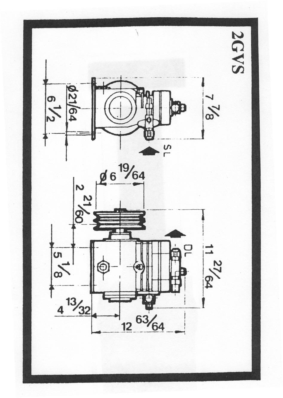
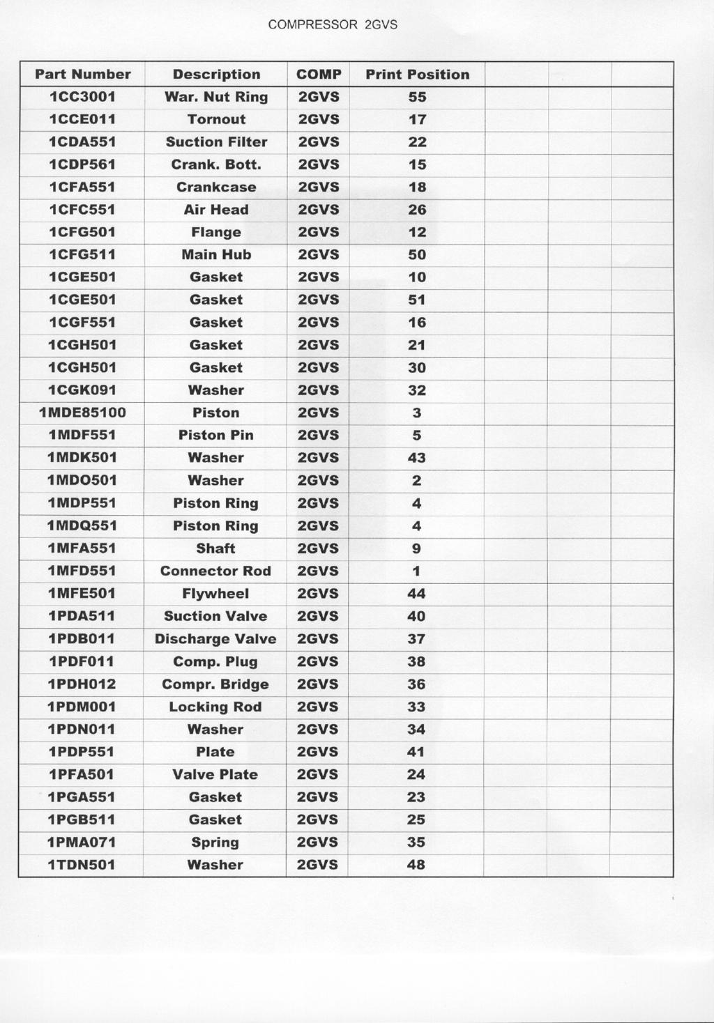
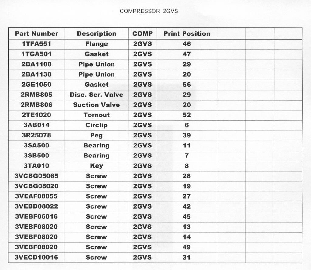
30 I ~ (4)" GI ~ CCRIN COMPRESSORE TIPO CODICE N ECO160 2GVS AGHFCHF DATA 20/07/2000, c' (2) lmdq551 (2) lmdp551 0 " (2) lmde (2) lmcea05 i (2) ludf551~ 0 2BAll 00 3ABO14\ ~~ I~ lcdul W ~ 62 4) ( lmddoll~~\111 J ~2RMB805 o~ /3VEAFOB065 (2) lmcdo88i 1. I ~0/ ~ (2) ::I ~lcgh501 /3VEAFO8055(8) L (2) lmfd551 ~lcdu162 (2) ~ / (4) lpdnoll, (4) lpmao71~ (4)lPDFDll~; 2TE1130-"". r.~. ~CBGDBD20 (2) (2) lpdmoll I lcfc551,,~ (2) lpdho12 ~ ~? (2) lpdhdll~ I'PGH55"-/.W r2ba1130 ~ ~ \\~. lpfa5dl I. ;!"'ij (i!j (2)lPDA551~~.,:{/:~ r / / (4) 3R25078~D "" ]. \ "'--L 2RMBBD6 ~lpga551j.aa...'1:):] ] ~ lcda5511 1CGH50 (2) lpdp551/ J I - j lpca505 I \ I lcfa551 ]. GE501 - ~- / \I. lpcb505 lc 3SE500 \ \ ~ /. I. lcfg511 ltdn501~" -,. \., ~ ~ "", /' /.,. ]),CGKO., ( 2) / "..:::::3VECD10016 "... "", '-,'... /. r-. ;..;.Jj ltfa551~~ ~ \. \\1 ~ foi..--- / ] lccq501 I 0:' :, ~lcg~551 lmdk501 ~\.~ \~.,. I 00 lmfe501~ ","" ".] (6) 3VEHF06016J 0~ ~~ / ~~~~(.. >: '~/] 0 \ J.. II.,L1CCEOll] / " /2GE1050 3VKBDO8022~ - ].! ] (6) 3VEHF08020 : ~ / ~.. I / / ~ lcdp561 lccdo01-"s. / / / / / / 3VEBFO8020 (12) 3TA010./// ~?\ ~ ~~ 3VEBFO8020 v l \ lmfa551 ~. ] ~ \ ~. 1C!'G501 3SA500lCGE501 (6) /,-....:. PAINT 3MVA1O OIL 3MRAOIOl E!!!.borato V!!.!"ific!!.to App!"Qvato ~ 0 '7
31 WARNING! To avoid injury or death due to inhalation of, or skin exposure to refrigerant, closely follow all safety procedures described in the Material Safety Data Sheet for the refrigerant and to all labels on refrigerant containers. Certain procedures common to refrigeration system service may expose personnel to liquid or vaporous refrigerant. Troubleshooting Procedures If functional difficulties are experienced, refer to the following troubleshooting chart for assistance. Troubleshooting Guide The following guide is provided to assist in analyzing problems that could occur. Symptom: Cause: Solution: Describes what is happening Suggests possible source Describes what must be done Symptom Cause Solution Restrictions in recovery line Pressure differential between system and recovery tank becomes too high - greater than 15 psig. Remove restriction in liquid recovery lines or tank. Tank needs to have minimum 3/4 ID valves. Slow liquid transfer. Restriction in flow Replace restrictive fittings and hoses with appropriate size to expedite transfer. EVAC running high head pressure back to recovery tank. Restriction in hoses going to tank. Replace with appropriately sized hoses and fittings. Run water over tank or add secondary water cooled condenser on liquid return line going to recovery tank. (RefTec has available secondary water cooled and air cooled condensers.) EVAC compressor won t restart. Continues on next page Capacity of recovery tank is too small or tank is overfilled. High concentration of noncondensibles Condenser fan not running. Compressor motor thermal overload open. Replace with appropriately sized tanks. Remove non-condensibles. Check fan motor and relay. Let unit cool down.
32 Symptom Cause Solution Recovery hose incorrectly connected, this may cause liquid to be injected into compressor EVAC slugging with liquid during liquid push/pull Verify that the system vapor and liquid lines are properly connected and that the vapor and liquid lines on recovery tank are connected correctly. Improper valves on recovery tank allowing liquid to be injected into compressor Verify that the liquid and vapor valves on the recovery tank are separate and that the recovery tank is no more than 80% full. 30
33 Manufacturers Limited Warranty Limited Warranty: RefTec warrants that the equipment will, under normal and anticipated use, be free from defects in refrigerant related parts for a period of one (1) year from and after the date of shipment, and be free from defects in electrical related parts for a period of ninety (90) days from and after the date of shipment, but in all cases excluding consumables and other matters as hereinafter provided. Labor is NOT covered and shall be the sole cost and responsibility of the Purchaser. The obligation of RefTec under this limited warranty is limited to the supplying of parts (excluding consumables) as hereinabove specifically provided. Parts shall be new or nearly new. RefTec shall be liable to replace the applicable parts only if (i) RefTec is properly notified by Purchaser upon discovery of the alleged defects, (ii) defective parts are returned to RefTec upon authorization with all transportation charges prepaid by Purchaser, (iii) RefTec's examination of the parts discloses to its satisfaction that the defects were not caused by the Purchaser or its agents and (iv) the parts are otherwise covered by RefTec's limited warranty. Purchaser shall be responsible to select the means of transportation and bear the cost of inbound and outbound freight expense associated with any replacement parts, and al risk of loss attendant thereto. Notwithstanding anything contained in this warranty to the contrary, (i) this limited warranty shall become null and void upon the use of any improper chemicals or in the event any modifications or improper service or installation is performed on the equipment, (ii) this limited warranty does not apply to consumable materials such as, but not limited to, indicator lamps, fuses, all fluids, filters, coatings, etc., and (iii) this limited warranty is applicable only to Purchaser, and no subsequent purchasers of the equipment from Purchaser shall be entitled to any warranty whatsoever from RefTec, express or implied. THIS WARRANTY CONSTITUTES THE SOLE AND EXCLUSIVE WARRANTY OF REFTEC WITH RESPECT TO THE EQUIPMENT, THERE ARE NO OTHER WARRANTIES, EXPRESS OR IMPLIED, AND REFTEC SPECIFICALLY DISCLAIMS ALL OTHER WARRANTIES, EXPRESS OR IMPLIED, INCLUDING (WITHOUT LIMITATION), ANY AND ALL WARRANTIES AS TO THE SUITABILITY OR MERCHANTABILITY OR FITNESS FOR ANY PARTICULAR PURPOSE OF THE EQUIPMENT FURNISHED HEREUNDER. THE EXCLUSIVE REMEDY OF PURCHASER AGAINST REFTEC FOR ANY BREACH OF THE FOREGOING LIMITED WARRANTY SHALL BE TO SEEK REPLACEMENT OF THE AFFECTED PARTS. IN NO EVENT WILL REFTEC'S LIABILITY IN CONNECTION WITH THE EQUIPMENT WHICH IS FOUND TO BE DEFECTIVE EXCEED THE AMOUNTS PAID BY PURCHASER TO REFTEC HEREUNDER FOR SUCH EQUIPMENT WHICH IS SPECIFICALLY FOUND TO BE DEFECTIVE. THESE LIMITATIONS APPLY TO ALL CAUSES OF ACTION IN THE AGGREGATE, BOTH AT LAW AND IN EQUITY, AND INCLUDING WITHOUT LIMITATION, BREACH OF CONTRACT, BREACH OF WARRANTY, REFTEC'S NEGLIGENCE, INFRINGEMENT, STRICT LIABILITY, MISREPRESENTATION AND OTHER TORTS AND CONTRACTUAL CLAIMS. EXCEPT FOR THE EXCLUSIVE REMEDY PROVIDED ABOVE FOR REFTEC'S BREACH OF THIS LIMITED WARRANTY, PURCHASER, FOR ITSELF AND ITS SUCCESSORS AND ASSIGNS, HEREBY WAIVES AND RELEASES REFTEC FROM ANY AND ALL OTHER CLAIMS OR CAUSES OF ACTION THEY HAVE AGAINST REFTEC ON ACCOUNT OF OR ASSOCIATED WITH THE EQUIPMENT PURCHASED HEREUNDER OR FOR REFTEC'S BREACH OF THIS LIMITED WARRANTY. IN NO EVENT SHALL REFTEC BE LIABLE FOR ANY INDIRECT, SPECIAL, INCIDENTAL, CONSEQUENTIAL OR PUNITIVE DAMAGES, SUCH AS, BUT NOT LIMITED TO, LOSS OF ANTICIPATED PROFITS, LOST SAVINGS, LOST REVENUES, FINES, OR OTHER ECONOMIC LOSS IN CONNECTION WITH OR ARISING OUT OF THE EXISTENCE, FURNISHING, FUNCTIONING OR USE OF ANY ITEM OF EQUIPMENT PROVIDED UNDER THIS AGREEMENT, EVEN IF REFTEC HAS BEEN ADVISED OF THE POSSIBILITY OF SUCH DAMAGES AND/OR SUCH DAMAGES ARE REASONABLE AND/OR FORESEEABLE. FURTHER, PURCHASER FOR ITSELF AND ITS SUCCESSORS AND ASSIGNS, WAIVES AND RELEASES ANY RIGHTS THEY MAY HAVE TO BRING AN ACTION ARISING OR RESULTING FROM THIS AGREEMENT, REGARDLESS OF ITS FORM, MORE THAN FIFTEEN (15) MONTHS AFTER SHIPMENT OF THE AFFECTED EQUIPMENT BY REFTEC TO PURCHASER. The provisions of this warranty shall supersede any contrary provisions contained in this agreement, any document supplied by RefTec to Purchaser or by Purchaser to RefTec, or any other agreement, written or oral, between Purchaser and RefTec, notwithstanding the fact hat he provisions contained in this warranty directly conflict with other terms or provisions of this agreement or such other documents, or that such other documents or agreements were provided, delivered, made or executed subsequent to this agreement unless such agreements are in writing, specifically refer to this agreement, specifically provide that they are amending this and are signed by the President of RefTec. 31
Refrigerant Recovery Unit, Model RRU134
 Installation, Operation & Maintenance Manual IOMM RRU134 Group: Refrigerant Effective: December 2000 Supersedes: New Refrigerant Recovery Unit, Model RRU134 1999 McQuay International Table of Contents
EVAC TM commercial CRH-500
 EVAC TM commercial CRH-500 High Pressure Electromechanical Commercial Refrigerant Recovery System OPERATION MANUAL Electromechanical Version 4.0 Staring S/N:35629 MODEL NUMBERS: CRH-A-230-3-E, CRH-A-240-1-E,
OPERATION MANUAL COPYRIGHT APPION INC - ALL RIGHTS RESERVED
 OPERATION MANUAL COPYRIGHT 2006 - APPION INC - ALL RIGHTS RESERVED Table of Contents Warnings and Safety Information 3 Refrigerant Storage Container Safety 3 Machine Usage 4 Standard Recovery Procedure
Operation and Maintenance Manual
 Warranty Information Ritchie Engineering guarantees YELLOW JACKET products to be free of defective material and workmanship which could affect the life of the product when used for the purpose for which
RecoverX Oil-Filled Hermetic Refrigerant Recovery System. Operation and Maintenance Manual
 RecoverX Oil-Filled Hermetic Refrigerant Recovery System Operation and Maintenance Manual Table of Contents Page General Safety Instructions 2-3 System Overview 3 Operating Guide 4 Restart Procedure 4
Enspeco RMS. The Enspeco Refrigerant Management. The following instructions will INSTRUCTIONS
 Enspeco AUTOMOTIVE REFRIGERANT MANAGEMENT SYSTEMS RMS 5000 INSTRUCTIONS The Enspeco Refrigerant Management System 5000 provides fast and efficient recovery, recycling and charging of automotive air conditioning
OPER LV Wheeler Way
 OPER RATING INSTRUCTIONS LV5 REFRIGERANT RECOVERY UNIT NATIONAL REFRIGERATION PRODUCTS 985 Wheeler Way Langhorne, PA 19047 Ph:(215) 638-8909 9 info@ @nrproducts.com LV5.DOC 9.17.2018 MODEL LV5 REFRIGERANT
OPERATING INSTRUCTIONS
 OPERATING INSTRUCTIONS MODEL LV20 LARGE CAPACITY REFRIGERANT RECOVERY UNIT NATIONAL REFRIGERATION PRODUCTS 985 WHEELER WAY LANGHORNE, PA 19047 (215) 638-8909 FAX (215) 638-9270 R01101 LV20.DOC NRP-OM-LV20
CLIMAGUARD Air-to-Air Outdoor Heat Exchangers INSTRUCTION MANUAL. Rev. H 2015 Pentair Equipment Protection P/N
 CLIMAGUARD Air-to-Air Outdoor Heat Exchangers TX23, TX33, TX38, TX52 Model INSTRUCTION MANUAL Rev. H 2015 Pentair Equipment Protection P/N 10-1008-221 87976519 TABLE OF CONTENTS RECEIVING THE HEAT EXCHANGER...3
MaxLite LED MICRO-T PANEL
 ` Installation Instructions General Safety Information To reduce the risk of death, personal injury or property damage from fire, electric shock, falling parts, cuts/abrasions, and other hazards read all
T-SERIES Air Conditioner. T62 Model INSTRUCTION MANUAL nvent Rev. F P/N
 T-SERIES Air Conditioner T62 Model INSTRUCTION MANUAL Rev. F P/N 10-1008-239 TABLE OF CONTENTS RECEIVING THE AIR CONDITIONER... 3 HANDLING AND TESTING THE AIR CONDITIONER... 3 INSTALLATION INSTRUCTIONS...
Ion Genesis II Pump Controller Digital Level Control with Pump Alternation and High Water Alarm
 Page 1 of 8 General Overview Thank you for purchasing an Ion Genesis controller. Take the time to read the instructions carefully before using this appliance. We strongly recommend that you keep this instruction
Owner s Manual Refrigerated Compressed Air Dryers Models F-3528, F-3529, F-3530, F-3531 & F-3532
 Owner s Manual Refrigerated Compressed Air Dryers Models F-3528, F-3529, F-3530, F-3531 & F-3532 Read carefully before attempting to assemble, install, operate or maintain the product described. Protect
PROAIR Water-Cooled Air Conditioner. CR43WC Model INSTRUCTION MANUAL
 PROAIR Water-Cooled Air Conditioner CR43WC Model INSTRUCTION MANUAL Rev. F 2018 nvent P/N 10-1008-167 87976466 TABLE OF CONTENTS HANDLING & TESTING THE AIR CONDITIONER...3 INSTALLATION INSTRUCTIONS...4
OPERATING INSTRUCTIONS
 OPERATING INSTRUCTIONS MODEL LV8 COMMERCIAL REFRIGERANT RECOVERY UNIT NATIONAL REFRIGERATION PRODUCTS 985 WHEELER WAY LANGHORNE, PA 19047 (215) 638-8909 FAX (215) 638-9270 A01001 7/11/96 NRP-OM-LV8 7/96
APPLICATION MANUAL FOR SCU SERIES COMPRESSOR UNITS AND SWU SERIES WATER COOLED CONDENSING UNITS
 APPLICATION MANUAL FOR SCU SERIES COMPRESSOR UNITS AND SWU SERIES WATER COOLED CONDENSING UNITS SCU-30 SWU-30 Napps Technology Corporation P.O. Box 3066 Longview, TX 75606-3066 Phone: (903) 758-2900 FAX:
MANUAL 8/12/05. Model BKP TM 100 INSTALLATION, OPERATION & MAINTENANCE. Commercial High Efficiency Heat Pipe Dehumidifier
 MANUAL 8/12/05 INSTALLATION, OPERATION & MAINTENANCE Commercial High Efficiency Heat Pipe Dehumidifier Model BKP TM 100 Heat Pipe Technology, Inc. 6904 Parke East Blvd. Tampa FL 33610 Tel: (813) 470-4250
High Performance Oilless Residential Light Commercial. Product Leadership Training Service Reliability
 High Performance Oilless Residential Light Commercial Product Leadership Training Service Reliability User Manual 2020-9000 Rev. 1 December 2017 WARRANTY Bacharach, Inc. (Bacharach) warrants to the buyer
Ion Endeavor Pump Controller Digital Level Control with Pump Alternation and High Water Alarm
 Ion Endeavor Controller Digital Level Control with Alternation Page 1 of 8 General Overview The Ion Endeavor is a pump controller that senses a water level of up to 72", has a configurable water level/pump
Rev. A AUGUST 2012 RNP SERIES REFRIGERATED COMPRESSED AIR DRYERS OPERATOR MANUAL RNP25 RNP35 RNP50
 3227447 Rev. A AUGUST 2012 RNP SERIES REFRIGERATED COMPRESSED AIR DRYERS OPERATOR MANUAL RNP25 RNP35 RNP50 GENERAL SAFETY INFORMATION 1. PRESSURIZED DEVICES: This equipment is a pressure containing device.
MaxLite LED VAPOR TIGHT LINEAR FIXTURES
 A cost effective LED Vapor Tight Fixture features a full length polycarbonate lens and a one-piece white glass reinforced polyester (GRP) body. Designed to meet or exceed seven to 10 foot-candles at 8
R100 Oil-Less Refrigerant Recovery Unit
 R100 Oil-Less Refrigerant Recovery Unit Operation Manual 1 INTRODUCTION Welcome to simple, efficient refrigerant recovery with your new YELLOW JACKET Refrigerant Recovery Unit, R100. This unit combines
Owner s Manual Refrigerated Compressed Air Dryers Models F-200, 250, 300 & F350
 Owner s Manual Refrigerated Compressed Air Dryers Models F-200, 250, 300 & F350 Read carefully before attempting to assemble, install, operate or maintain the product described. Protect yourself and others
Owner s Manual Refrigerated Compressed Air Dryers Model F-100
 Owner s Manual Refrigerated Compressed Air Dryers Model F-100 Read carefully before attempting to assemble, install, operate or maintain the product described. Protect yourself and others by observing
Rev. E 2013 Pentair Technical Products P/N Distributed by: McLean Parts
 PROAIR Water-Cooled Air Conditioner CR43WC Model INSTRUCTION MANUAL Rev. E 2013 Pentair Technical Products P/N 10-1008-167 TABLE OF CONTENTS HANDLING & TESTING THE AIR CONDITIONER...3 INSTALLATION INSTRUCTIONS...4
ion Genesis Pump Controller
 High Water Alarm Document No.: IONG_OM Page 1 of 7 Table of Contents Safety Precautions.......................... 1 General Overview.......................... 1 Installation.................................2
OPERATION MANUAL FOR REFRIGERANT RECOVERY
 FOR REFRIGERANT RECOVERY CAUTION Explosion Hazard. Do NOT use with hydrocarbons. See page 4. WARNING TO REDUCE THE RISK OF INJURY OR PRODUCT DAMAGE, READ OPERATION MANUAL PRIOR TO OPERATING PRODUCT. OPERATION
Owner s Manual Refrigerated Compressed Air Dryer Model F-50
 Owner s Manual Refrigerated Compressed Air Dryer Model F-50 Read carefully before attempting to assemble, install, operate or maintain the product described. Protect yourself and others by observing all
EBAC MODEL CD30 INDUSTRIAL DEHUMIDIFIER OWNER S MANUAL
 EBAC MODEL CD30 INDUSTRIAL DEHUMIDIFIER OWNER S MANUAL Ebac Industrial Products, Inc. 700 Thimble Shoals Blvd, Suite 109 Newport News, VA. 23606-2575 Tel: (757) 873 6800 Fax: (757) 873 3632 Website www.ebacusa.com
DOM MODEL SERIAL NUMBER VOLTAGE/HERTZ/PHASE
 DOM MODEL SERIAL NUMBER VOLTAGE/HERTZ/PHASE DON T JUST DO IT! Make sure the chiller you buy has been ETL listed as a complete unit. Intertek Testing Services, testing is your only assurance that your chiller
Superdryer Dehumidifiers
 Superdryer Dehumidifiers Installation and Operations Manual Read and Save These Instructions Distributed Exclusively By: Air Cleaning Equipment, Inc. Broadway, NC 27505 Phone: 919-258-3330 www.aircleaningequipment.com
Rev. None AUGUST 2012 MDM SERIES MODULAR MEMBRANE AIR DRYERS OPERATOR MANUAL MDM1 MDM4 MDM9 MDM13 MDM24 MDM49 MDM66 MDM106 MDM138
 7428146 Rev. None AUGUST 2012 MDM SERIES MODULAR MEMBRANE AIR DRYERS OPERATOR MANUAL MDM1 MDM4 MDM9 MDM13 MDM24 MDM49 MDM66 MDM106 MDM138 1.0 SAFETY All compressed gases, including air, can be dangerous.
OPERATION AND MAINTENANCE INSTRUCTIONS FOR ROOF TOP HEAT PUMPS AND CEILING PLENUMS
 OPERATION AND MAINTENANCE INSTRUCTIONS FOR ROOF TOP HEAT PUMPS AND CEILING PLENUMS TABLE OF CONTENTS I. General Information.................................................. 2 II. Standard Ceiling Plenum
347002K/177002K/34900
 Service Manual Models: 347002K/177002K 34900/347012K Manifold Block Style Recovery/Recycling/Recharging Unit For R-12 or R-134a Only TABLE OF CONTENTS: Theory of Operation and Safety Precautions... 2 Depressurizing
NON-CYCLING REFRIGERATED AIR/GAS DRYERS QPNC 75 to QPNC 250 OPERATOR S MANUAL
 NON-CYCLING REFRIGERATED AIR/GAS DRYERS QPNC 75 to QPNC 250 OPERATOR S MANUAL DATE OF PURCHASE: MODEL: SERIAL NO.: Record above information from nameplate. Retain this information for future reference.
IMPORTANT INSTRUCTIONS
 IMPORTANT INSTRUCTIONS W Fan Force Electric Space Heater DANGER ELECTRIC SHOCK OR FIRE HAZARD Figure 1 Covers all W Series models WARNING Read Carefully - These instructions are written in an effort to
EBAC MODEL KOMPACT INDUSTRIAL DEHUMIDIFIER OWNER S MANUAL
 EBAC MODEL KOMPACT INDUSTRIAL DEHUMIDIFIER OWNER S MANUAL KOMPACT OWNERS MANUAL Page 1 of 9 INTRODUCTION Designed for a wide range of applications, the Kompact is a rugged, industrial unit, which utilizes
OPERATING INSTRUCTIONS
 OPERATING INSTRUCTIONS MODEL RLV-700 REFRIGERANT RECOVERY / RECYCLING UNIT (PATENTED) NATIONAL REFRIGERATION PRODUCTS 985 Wheeler Way Langhorne, PA 19047 (215) 638-8909 FAX (215) 638-9270 REVISED 03-21-2018
EBAC MODEL CD60 INDUSTRIAL DEHUMIDIFIER OWNER S MANUAL
 EBAC MODEL CD60 INDUSTRIAL DEHUMIDIFIER OWNER S MANUAL CD60 OWNERS MANUAL Page 1 of 9 INTRODUCTION Designed for a wide range of applications, the CD60 dehumidifier is a rugged, industrial unit which utilizes
Air Pump Up to 800 gallons
 Air Pump Up to 800 gallons REMINDER CALL 1-888-755-6750 BEFORE RETURNING TO STORE. PACKAGE CONTENTS ITEM #PBPAPK40W Questions, problems, missing parts? Before returning to your retailer, call our customer
Air Cleaning Equipment, Inc. 303 N. Main St. Broadway, NC iers.com
 Read and Save These Instructions Horizon Galaxy - Installation and Operations Manual Air Cleaning Equipment, Inc. 303 N. Main St. Broadway, NC 27505 www.horizondehumidif iers.com 1 Safety Notes: The Horizon
REFRIGERATED DROP-INS (2-6)FT-DI Installation and Operating Manual
FT-DI Installation and Operating Manual") REFRIGERATED DROP-INS (2-6)FT-DI Installation and Operating Manual For service information call 800-544-3057 Please have the following information available before calling. Information can be found on
REFRIGERATED DROP-INS (2-6)FT-DI Installation and Operating Manual For service information call 800-544-3057 Please have the following information available before calling. Information can be found on
Panel Mounted Heat Exchangers by Dantherm, Inc.
 Panel Mounted Heat Exchangers by Dantherm, Inc. PRODUCT INFORMATION MANUAL C0028 003 Pinnacle OM Manual Rev AB Page 1 of 14 Dantherm, Inc. 110 Corporate Drive, Suite K Spartanburg, SC 29303 Tel # +1 864
EBAC MODEL BD-150 ( ) INDUSTRIAL DEHUMIDIFIER OWNER S MANUAL
 INDUSTRIAL DEHUMIDIFIER OWNER S MANUAL") EBAC MODEL BD-150 (1025000) INDUSTRIAL DEHUMIDIFIER OWNER S MANUAL BD-150 OWNERS MANUAL Page 1 of 12 INTRODUCTION Designed for a wide range of applications, the BD-150 dehumidifier is a super high capacity
EBAC MODEL BD-150 (1025000) INDUSTRIAL DEHUMIDIFIER OWNER S MANUAL BD-150 OWNERS MANUAL Page 1 of 12 INTRODUCTION Designed for a wide range of applications, the BD-150 dehumidifier is a super high capacity
SPECTRACOOL Air Conditioner. N17 Model INSTRUCTION MANUAL. Rev. G 2015 Pentair Equipment Protection P/N
 SPECTRACOOL Air Conditioner N17 Model INSTRUCTION MANUAL Rev. G 2015 Pentair Equipment Protection P/N 89117329 89117329 TABLE OF CONTENTS RECEIVING THE AIR CONDITIONER...3 HANDLING AND TESTING THE AIR
EBAC MODEL NEPTUNE INDUSTRIAL DEHUMIDIFIER OWNER S MANUAL
 EBAC MODEL NEPTUNE INDUSTRIAL DEHUMIDIFIER OWNER S MANUAL NEPTUNE OWNERS MANUAL Page 1 of 9 INTRODUCTION Designed for a wide range of applications, the Neptune dehumidifier is a super high capacity industrial
IW-25-2 Dehumidifier Installation & Operations. Manual
 IW-25-2 Dehumidifier Installation & Operations Installation and Operation Manual Manual IW-25-1 Dehumidifier Please Read and Save These Instructions Please Read and Save These Instructions Innovative Dehumidifier
DRY AIR SYSTEMS, INC Metro Boulevard Maryland Heights, Missouri (314) fax (314)
 fax (314)") DRY AIR SYSTEMS, INC. 2655 Metro Boulevard Maryland Heights, Missouri 63043 (314) 344-1114 fax (314) 344-0677 HD SERIES DRIERS TABLE OF CONTENTS WHY AN AIR DRYER 3 WHAT IS A DESICCANT AIR DRYER 3 Desiccant
DRY AIR SYSTEMS, INC. 2655 Metro Boulevard Maryland Heights, Missouri 63043 (314) 344-1114 fax (314) 344-0677 HD SERIES DRIERS TABLE OF CONTENTS WHY AN AIR DRYER 3 WHAT IS A DESICCANT AIR DRYER 3 Desiccant
PROAIR Air Conditioner
 INSTRUCTION MANUAL PROAIR Air Conditioner CR29 Protecting Electronics. Exceeding Expectations. Pentair Technical Products Rev. D 2011 Pentair Technical Products P/N 10-1008-121 89055732 TABLE OF CONTENTS
REFRIGERANT RECOVERY DEVICES AND ACCESSORIES
 DEVICES AND ACCESSORIES DEVICES AND ACCESSORIES PROMAX RECOVERY DEVICES PROMAX designs, engineers, and manufacturers the highest quality service equipment and makes it easy to use for all refrigerant handling
REFRIGERANT RECOVERY SYSTEMS
 REFRIGERANT RECOVERY 99 Washington Street Melrose, MA 02176 Phone 781-665-1400 Toll Free 1-800-517-8431 Visit us at www.testequipmentdepot.com RECOVERY YELLOW JACKET HVAC&R HOSES YELLOW JACKET YJ-LTE Refrigerant
OWNER S MANUAL (English)
") TR600 Series Refrigerant Recovery Machines OWNER S MANUAL (English) Français, Español, Deutsch and latest updates: www.cpsproducts.com Series: TR600, TR610, TR600C, TR610C, TR600S, TR600K, TR600E TO BE
TR600 Series Refrigerant Recovery Machines OWNER S MANUAL (English) Français, Español, Deutsch and latest updates: www.cpsproducts.com Series: TR600, TR610, TR600C, TR610C, TR600S, TR600K, TR600E TO BE
NEUTRONICS MINI ID R-1234yf REFRIGERANT IDENTIFIER OPERATION MANUAL
 NEUTRONICS MINI ID R-1234yf REFRIGERANT IDENTIFIER OPERATION MANUAL 456 Creamery Way, Exton, PA 19341, USA Phone: 610.524.8800 Fax: 610.524.8807 Email: info@refrigerantid.com www.refrigerantid.com Page
OWNER/OPERATOR MANUAL COMPONENTS, INSTALLATION, OPERATION AND SERVICE INSTRUCTIONS
 OWNER/OPERATOR MANUAL COMPONENTS, INSTALLATION, OPERATION AND SERVICE INSTRUCTIONS REFRIGERATED COMPRESSED AIR DRYER WRA-0050 WRA-0200 WARNING READ ALL INFORMATION IN THIS MANUAL BEFORE BEGINNING INSTALLATION
READ AND UNDERSTAND THESE INSTRUCTIONS BEFORE OPERATING THE MACHINE
 XAACT Xtract 200 INFORMATION & OPERATING INSTRUCTIONS READ AND UNDERSTAND THESE INSTRUCTIONS BEFORE OPERATING THE MACHINE 78-00018 Rev B 032912 1 CONTENTS: Machine Specifications............ 2 Record Important
Installation and Operation Manual. 445 Procedures Cart. Page 3. Page 5. Page 8. Page 10. Important Information Page 2. Installation.
 Important Information Page 2 Installation and Operation Manual 445 Procedures Cart Installation Page 3 Description Page 5 Components Overview Page 6 Controls & Indicators Page 7 Operation Page 8 HOT Operator
Turbo Air Speed up the Pace of Innovation TBB-4SB CAUTION! PLEASE KEEP POWER SWITCH ON BEFORE OPERATING THIS EQUIPMENT
 Turbo Air Speed up the Pace of Innovation CAUTION! PLEASE KEEP POWER SWITCH ON BEFORE OPERATING THIS EQUIPMENT Underbar Equipment Back Bars Installation and Operation Manual Please read this manual completely
G Series SAVE THESE INSTRUCTIONS. (Model B) Convector Heater for Hazardous Locations GENERAL! INSTALLATION
 Convector Heater for Hazardous Locations GENERAL! INSTALLATION") G Series (Model B) Convector Heater for Hazardous Locations Type G-Series Convection Heaters are designed for use in Class I, Div. I hazardous environments. Units without control options are suitable for
G Series (Model B) Convector Heater for Hazardous Locations Type G-Series Convection Heaters are designed for use in Class I, Div. I hazardous environments. Units without control options are suitable for
Refrigerant Recovery Machine. Model No Operating Manual
 Refrigerant Recovery Machine Model No. 25700 Operating Manual Safety Precautions WARNING : TO PREVENT PERSONAL INJURY AND / OR EQUIPMENT DAMAGE, CAUTION - Risk of injury. This equipment should only be
READ AND UNDERSTAND THESE INSTRUCTIONS BEFORE OPERATING THE MACHINE
 XAACT Xtract 500 INFORMATION & OPERATING INSTRUCTIONS READ AND UNDERSTAND THESE INSTRUCTIONS BEFORE OPERATING THE MACHINE 78-00015 Rev B 032912 1 CONTENTS: Machine Specifications............ 2 Record Important
InstructIon Manual KrEs EQuIPMEnt stands
 Instruction Manual Instruction Manual SELF-CONTAINED AND REMOTE Kairak KRES model refrigerated equipment stand units are available in many lengths from 36 to 120 inches long. These units are available
User s Manual and Warranty Information for Counterweighted Chain Drive ThyssenKrupp Access
 II User s Manual and Warranty Information for Counterweighted Chain Drive ThyssenKrupp Access Part #2139703 Rev. G II Table of Contents Introduction...3 Elevator Overview...4 Description of Features...5-7
Product Data. Features/Benefits. 19XB Positive Pressure Storage System
 Product Data 19XB Positive Pressure Storage System 19XB028 Copyright 1992 Carrier Corporation 19XB052 Carrier s Positive Pressure Storage (PPS) System ensures the critical conservation of refrigerants
OPERATION & INSTALLATION MANUAL
 OPERATION & INSTALLATION MANUAL Model: SIO 14 & SIO 18 Electric Tankless Hot Water Generators Table of Contents SAFETY INFORMATION... 1 INTRODUCTION... 2 Unit Operation:... 2 Unit Freezing:... 3 Maintenance:...
XC Portable Air Conditioning
 PORTABLE AIR CONDITIONERS XC Portable Air Conditioning XC-14A, XC-22A, XC-30A Models USER & INSTALLATION MANUAL www.xpcc.com 2013 Xtreme Power Conversion Corporation. All rights reserved. Table of Contents
GRF-SERIES REFRIGERATION TYPE NON CYCLING STANDARD
 Great Lakes Air Products 1515 S. Newburgh Road Westland, MI 48186 PH: 734-326-7080 www.glair.com COMPRESSED AIR DRYER INSTRUCTION MANUAL GRF-SERIES REFRIGERATION TYPE NON CYCLING STANDARD Contents Introduction
R E D I C O N T R O L S
 R E D I C O N T R O L S File Literature Number 1144-01-1 Installation Operation & Maintenance Manual CONTINUOUS REFRIGERANT DEHYDRATOR Model: CD-120 For use with Refrigerants R-11, R-123, R-12, R-22, R-134a
TrueClean ToteCleaner
 TrueClean ToteCleaner Installation, Operation, and Maintenance Manual www.trueclean.us TrueClean Check Valve Table of Contents Introduction.... 1 About... 1 Warranty... 2 Safety... 3 Important Safety Information....
Operator s Manual. Histology Bath
 Operator s Manual Histology Bath 110-827 05.09.12 Table of Contents Introduction... 2 General Safety Information... 2 Safety Recommendations... 3 Unpacking Your Histology Bath...4 Contents...4 Components
TrueClean ToteCleaner
 TrueClean ToteCleaner Installation, Operation, and Maintenance Manual www.trueclean.us TrueClean Check Valve Table of Contents Introduction.... 1 About... 1 Warranty... 2 Safety... 3 Important Safety Information....
14+ SEER R-410a AIR CONDITIONERS. Aluminum Coil Series. Efficiencies up to 14+ SEER/12 EER. Nominal Sizes Ton. Capacities 16.
 14+ SEER R-410a Coil Company, L.P AIR CONDITIONERS UNITED STATES PATENT #D557,394S #D557,395S R-410A Aluminum Coil Series Efficiencies up to 14+ SEER/12 EER Nominal Sizes 1.5-5 Ton Capacities 16.6 to 56
WMWLB / WMWFM / WTWLB / WTWFM Series Hydronic Heating Unit
 January 2008 WMWLB / WMWFM / WTWLB / WTWFM Series Hydronic Heating Unit Installation Operation Maintenance The units are designed for permanent up flow, counter flow, or horizontal left or right airflow
DH07, DH07A /DH08, DH08A CONVECTED AIR DISH HEATERS
 DH07, DH07A /DH08, DH08A CONVECTED AIR DISH HEATERS DH07 shown INSTALLATION, OPERATION & MAINTENANCE MANUAL Manual P/N 92448 Rev. G 04/02/2009 Copyright 1998 Aladdin Temp-Rite Changes may be made to the
OPERATION, SERVICE & PARTS MANUAL
 OPERATION, SERVICE & PARTS MANUAL BROASTER 620N & 621 EASY BREADER Be sure ALL installers read, understand, and have access to this manual at all times. MODEL 620N MODEL 621 Genuine Broaster Chicken, Broasted,
Installation and Operation Manual. 445 Procedures Cart. Page 3. Page 5. Page 8. Page 10. Important Information Page 2. Installation.
 Important Information Page 2 Installation and Operation Manual 445 Procedures Cart Installation Page 3 Description Page 5 Components Overview Page 6 Controls & Indicators Page 7 Operation Page 8 HOT Operator
PROAIR Air Conditioner. CR29 Model INSTRUCTION MANUAL. Rev. F 2015 Pentair Equipment Protection P/N
 PROAIR Air Conditioner CR29 Model INSTRUCTION MANUAL Rev. F 2015 Pentair Equipment Protection P/N 89104461 89104461 TABLE OF CONTENTS RECEIVING THE AIR CONDITIONER...3 HANDLING AND TESTING THE AIR CONDITIONER...3
MAC N-407 Air-Cooled Chiller
 MAC036-01-N-407 Air-Cooled Chiller Air-Cooled Chillers for Global Residential and Light Commercial MicroClimates MAC036 NOMENCLATURE BREAKDOWN MAC036-01 - N - 407 Refrigerant Type Air-Cooled Chiller 036=
USER MANUAL SAVE THESE INSTRUCTIONS
 USER MANUAL Model: PM50 SAVE THESE INSTRUCTIONS CAUTION Federal (USA) law restricts this device to sale by or on the order of a physician. 300 Held Drive Tel: (+001) 610-262-6090 Northampton, PA 18067
Desiccant Tank Retrofit Kit for CD100/CS101 dehumidifying dryers
 Desiccant Tank Retrofit Kit for CD100/CS101 dehumidifying dryers Installation Instructions Instant Access Parts and Service (800) 458-1960 (814) 437-6861 www.conairnet.com The Conair Group, Inc. One Conair
Pro-Set TRA21 SERIES Mobile Multiple Refrigerant Recovery / Recycle System
 Pro-Set TRA21 SERIES Mobile Multiple Refrigerant Recovery / Recycle System Certified by ITS to meet SAE J2810 for R-134a Designed to meet new SAE J2851 for R-1234yf MANUAL GENERAL INFORMATION Table of
Compact Equipment Warranty Policy
 006 07.15 Compact Equipment Warranty Policy 07/2015 Table of Contents Preface Page 1 Distributor s Warranty Responsibilities Page 1 Standard Warranties Page 2 Warranty Coverage Page 2 Warranty Limitations
COMPRESSED AIR DRYER. SAFETY... Page 2 MAINTENANCE... Page 5. INSTALLATION... Page 3 PARTS AND KITS... Page 6
 OWNERS MANUAL BOSS COMPRESSED AIR DRYER Distributed by Air & Vacuum Process, Inc. Phone: 281-866-9700 Fax: 281-866-9717 Email: sales@airvacuumprocess.com SAFETY... Page 2 MAINTENANCE... Page 5 INSTALLATION...
Calhoon MEBA Engineering School. Study Guide for Proficiency Testing Refrigeration
 Calhoon MEBA Engineering School Study Guide for Proficiency Testing Refrigeration 1. To prevent an injury when working with refrigerants, what safety precautions are necessary? 2. When halogens are in
T-SERIES Air Conditioner. T29 Model INSTRUCTION MANUAL. Rev. D 2015 Pentair Equipment Protection P/N
 T-SERIES Air Conditioner T29 Model INSTRUCTION MANUAL Rev. D 2015 Pentair Equipment Protection P/N 89104464 89104464 TABLE OF CONTENTS RECEIVING THE AIR CONDITIONER...3 HANDLING AND TESTING THE AIR CONDITIONER...3
Installation and Testing of Inverted Bucket Steam Traps Manual
 Installation and Testing of Inverted Bucket Steam Traps Manual 307-EN Please read and save these instructions Armstrong IB Traps Installation Before Installing Run pipe to trap. Before installing the trap,
Caresaver Universal Refrigerant Recovery Unit
 Operation Manual Caresaver Universal Refrigerant Recovery Unit 2 CONTENTS CHAPTER 1 INTRODUCTION AND OVERVIEW Specifications 3 Health and Safety 4-5 Component Location and Identification 6-9 CHAPTER 2
LABORATORY AIR COMPRESSORS AND VACUUM PUMPING SYSTEMS
 SECTION 22 20 00 LABORATORY AIR COMPRESSORS AND VACUUM PUMPING SYSTEMS PART 1 - GENERAL 1.1 RELATED DOCUMENTS: A. The Conditions of the Contract and applicable requirements of Division 1, "General Requirements",
Blade Series Heat Exchanger Operation and Installation
 Blade Series Heat Exchanger Operation and Installation *IMPORTANT* For safe and satisfactory operation, please read the following instructions. Keep these instructions for future reference. Some information
IMPORTANT INFORMATION - PLEASE READ CAREFULLY
 Honeywell Garrett Direct Fit Performance Intercooler 2015+ 3.5L / 2.7L Ford F150 EcoBoost Bill of Materials and Precautions Application: 2015+ Ford F150 3.5L / 2.7L Eco Boost Part Number: 870702-6001 Part
A2Z Ozone, Inc. PRODUCT MANUAL
 A2Z Ozone, Inc. PRODUCT MANUAL INSTALLATION & OPERATION MANUAL CE www.a2zozone.com Rev. 02142018 CONTENTS Page Important Safety Instructions... Specifications... Installation Instructions... 3 4 5 Troubleshooting...
Installation and Owner Man u al
 T H R E E P H A S E Evaporator Fan Control System Installation and Owner Man u al WARNING The installation of this device should be done only by competent personnel, experienced in electrical wiring, and
INSTRUCTIONS! DO NOT DISCARD!
 INSTRUCTIONS! DO NOT DISCARD! CAUTION! Do NOT install where injury might occur due to Moving parts, Sharp corners, Hot surfaces or electrical components d N0417 Page 1 of 10 INSTALLATION INSTRUCTIONS CAUTION
MACH N-407 Heat Pump Air-Cooled Chiller
 MACH060-01-N-407 Heat Pump Air-Cooled Chiller Heat Pump Air-Cooled Chillers for Global Residential and Light Commercial Microclimates MACH NOMENCLATURE BREAKDOWN MACH-060-01 - N - 407 Refrigerant Type
EBAC MODEL CD425 ( ) INDUSTRIAL DEHUMIDIFIER OWNER S MANUAL
 INDUSTRIAL DEHUMIDIFIER OWNER S MANUAL") EBAC MODEL CD425 (1018110) INDUSTRIAL DEHUMIDIFIER OWNER S MANUAL Ebac Industrial Products, Inc. 700 Thimble Shoals Blvd, Suite 109 Newport News, VA. 23606-2575 Tel: (757) 873 6800 Fax: (757) 873 3632
EBAC MODEL CD425 (1018110) INDUSTRIAL DEHUMIDIFIER OWNER S MANUAL Ebac Industrial Products, Inc. 700 Thimble Shoals Blvd, Suite 109 Newport News, VA. 23606-2575 Tel: (757) 873 6800 Fax: (757) 873 3632
User's Manual. and Warranty Information. ThyssenKrupp. ThyssenKrupp Access
 LIMITED WARRANTY Limited Warranty: Subject to the limitations set forth below, THYSSENKRUPP ACCESS, 4001 East 138th Street, Grandview, Missouri 64030, warrants to the ORIGINAL PURCHASER ONLY that the Volant
GENESIS Air Conditioner. M52 3-Phase Model INSTRUCTION MANUAL. Rev. H 2013 Pentair Equipment Protection P/N
 GENESIS Air Conditioner M52 3-Phase Model INSTRUCTION MANUAL Rev. H 2013 Pentair Equipment Protection P/N 10-1008-202 87976500 TABLE OF CONTENTS RECEIVING THE AIR CONDITIONER...3 HANDLING AND TESTING THE
Model R060 Installation - Operation Manual
 Residential Heat Pump Water Heaters Model R060 Installation - Operation Manual Important Note Read this entire manual before beginning installation Manufactured By: 6670-A Corners Industrial Court Norcross,
Operation Manual. Instructions for Installation, Operation & Maintenance. PortaPac 5-, 8 and 10-ton Portable Air Conditioners
 Operation Manual PortaPac 5-, 8 and 10-ton Portable Air Conditioners A AirPac, Incorporated AirPac Technology Park 888 Shenandoah Shores Road Front Royal, Virginia 22630 U.S.A. Toll Free 888-324-7722 Web:
T-Series Air Conditioner T15 Model
 INSTRUCTION MANUAL T-Series Air Conditioner T15 Model Protecting Electronics. Exceeding Expectations. McLean Cooling Technology 11611 Business Park Blvd N Champlin, MN 55316 USA Tel 763-323-8200 Fax 763-576-3200
IMPORTANT SAFETY INSTRUCTIONS EC-AG1-25 EC-AG1, EC-AG2 SAVE THESE INSTRUCTIONS.
 IMPORTANT SAFETY INSTRUCTIONS 2 1. Read and Follow All Instructions 2. Read this manual completely before attempting installation. 3. All permanent electrical connections should be made by a qualified