5/10/16Hp (HE) 5/8Hp (HT) MODEL : AM160FNBFEB/EU, AM160FNBFGB/EU, AM250FNBFEB/EU, AM250FNBFGB/EU AM160FNBDEH/EU, AM320FNBDEH/EU, AM500FNBDEH/EU
|
|
|
- Gavin Hodge
- 5 years ago
- Views:
Transcription

")


1 New DVM Hydro Unit (HT/HE) Model 5/10/16Hp (HE) 5/8Hp (HT) MODEL : AM160FNBFEB/EU, AM160FNBFGB/EU, AM250FNBFEB/EU, AM250FNBFGB/EU AM160FNBDEH/EU, AM320FNBDEH/EU, AM500FNBDEH/EU
2 1 Product Overview and Features Product Structure New Features Disassembly and Reassembly 5 Planar Figure and Parts List Installation and Service Precautions Circuits External Contacts Point / Indoor Unit Control Flow Troubleshooting References
3 1. Product Overview and Features Low temp. Heating/ Hot water supply Solution Efficient solution Low temp. Heating/ Hot water supply Solution Efficient solution


")
 Hot Water")
4 1. Product Overview and Features Various Applications Various Outdoor Unit Combination ( DVM S, DVM S HR, DVM Water ) Outdoor Side Water Solution Load Side DVM S DVM S HR DVM +4 HP/HR AHU (Water coil) DVM Water DVM Geo Hydro Unit (5/10/16HP) UFH Water Heating (Heating by water) FCU DVM ECO Hydro Unit HT(5/8HP) Hot Water Supply (Water heating)
5 1. Product Overview and Features Specifications Comparison Specification Company X Company M SAMSUNG LRD- LRD- PWFY-P100V PWFY-P200 AM160FN AM320FN AM500FN L3200A L5200A M-E-AU VM-E-AU BDEH BDEH BDEH Heating capacity [kw] Cooling capacity [kw] Cooling Heating Rated flow rate [LPM] Rated flow rate [LPM] Dimension s WxHxD (mm) x 450 x x 450 x x 627 x x 627 x x 627 x 330 Net weight kg Installation space Area ( m2 ) Volume ( m3 )
 VS Company M (PWFY-P100VM-E-BU) VS Operation Mode Heating Heating Same Heating Same Heating Same LINE-UP (Heating Capa/ The number of models) 16/25 (4) 25 (1) 11 / 14 /16 (6) -")
6 1. Product Overview and Features Specifications Comparison : The competitor comparison 25kW capacity lineup superiority SAMSUNG (AM160/250FNBFEB AM160/250FNBFGB) Company X (ARNH08GK3A2) VS Company D (EKHBRD011~ 016ABV1) VS Company M (PWFY-P100VM-E-BU) VS Operation Mode Heating Heating Same Heating Same Heating Same LINE-UP (Heating Capa/ The number of models) 16/25 (4) 25 (1) 11 / 14 /16 (6) (1) Max. Water Temp( ) Same 80 Same 70 Operation Range( ) (Hot Water supply) Operation Ratio(%) (A2A+A2W) -20 ~ ~ 35 Same -20 ~ 35 Same -20 ~ ~ ~ 130 Same 50 ~ 130 Same 50 ~ 150 Water Pipe Refrigerant pipe Noise INLET 25 (PT) 25 (PT) Same 25 (PF) Same 19 (PT) - OUTLET 25 (PT) 25 (PT) Same 25 (PF) Same 19 (PT) - Liquid Same 9.52 Same 9.52 Same GAS Same Same db(a) 43/ Same (16/25) (1x1.5m Manual) (1.5x1.5m Manual) (1x1.5m Manual) (Manual) Weight (kg) SIZE (WxHxD) 518x1210x x1080x x1210x x800x300 - Outside View
7 1. Product Overview and Features Operating Range -Hydro unit
8 Operating Range -Hydro unit HT Ta[ DB] 43 Continuous cooling operation possible, with connecting to HR LWT[ ] Ta : Ambient temperature LWT : Leaving water temperature


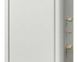
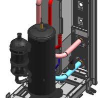
9 2. Product Structure Dimensions Parts Layout H 626mm W 520mm D 330mm Ⅰ Ⅱ Ⅲ Ⅳ Ⅴ One hole for each of the power cord and the communication cable and a knock- out hole for external cabling Designed as a Cabinet NCT. For consistence appearance, die cast parts adopted for Cabi -RH/LF. Consists of a plate-type heat exchanger, an EEV, a defrost bypass V/V and a flow switch. The pipe of the refrigerant is welded. The pipes of water are PT 1 male screws for 5Hp&10Hp and PT 1-1/4 male screws for 16Hp.
 INV PBA CONTROL KIT")


 Refrigerant pipe : Flare Type (3/8")
10 2. Product Structure Dimension Parts Layout MAIN PBA (NASA Protocol) INV PBA CONTROL KIT H 1210mm ASSY CABI PARTS EMI ASSY TUBE PARTS : * NEW PARTS : R410A Control EEV R134a Low pressure sensor ASSY COND / EVAP PARTS ASSY FAN PARTS W 518mm D 330mm ASSY COMP PARTS Ⅰ Ⅱ Ⅲ Ⅳ Ⅴ One hole for each of the power cord and the communication cable Designed as a Cabinet P/D + NCT, Hydro Unit(HE) Same design. Inner structure : R-134a Cycle Parts. (R-134a Compressor, PHE(2EA), EEV(2EA), C-Box) Refrigerant pipe : Flare Type (3/8 +5/8 ) Water pipe : 5/8Hp PT 1


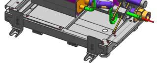


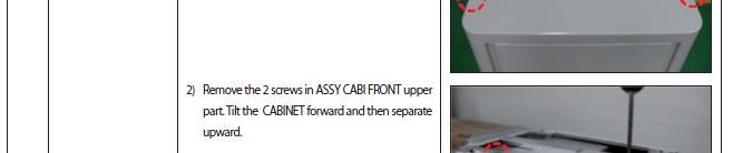
11 2. Product Structure Assembly procedures(5/10/16hp) [Step 1]: Assembly ASS'Y [Step 2]: Assembly ASS'Y [Step 3]: Assembly ASS'Y CABI BASE COND. RH/LT. [Step 4]: Assembly ASS'Y CONTROL BOX [Step 5]: Assembly ASS'Y CABI FRONT/BACK. [Step 6]: Assembly ASS'Y CABI TOP


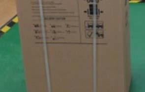
12 2. Product Structure Assembly procedures(5/10/16hp) [Step 1]: Assembly ASS'Y COMP. [Step 2]: Assembly ASS'Y COND/EVAP. [Step 3]:Assembly ASS'Y TUBE Parts. [Step 4]: Assembly COMP FELT and SUB MATERIAL. [Step 5]: Assembly CABINET(1) [Step 6]: Assembly CONTROL [Step 7]: Assembly CABINET(2) [Step 8]: Packing


13 2. Product Structure


")


14 2. Product Structure (DVM Hydro Unit HT)
15 2. Product Structure CYCLE DIAGRAM 5/10/16HP Symbol Description Symbol Description A EEV T1 EVA In B Defrost BP Valve T2 EVA Out Ref. Gas T2 T4 Water Out C Check Valve T3 Water In D PHX T4 Water Out E Flow Switch C D B T3 E Water In Ref. Liq A T1
16 2. Product Structure CYCLE DIAGRAM DVM Hydro Unit HT (5/8 Hp) HPS V_4W T_D T_CT INV LPS T_SUC AC E T_CO E_M PHE 2 PHE 1 T_EO E_EV E T_EI F_S TEW _ T_LW 5/8 3/8 Name INV Inveter Compressor PHE1 Plate Heat Excanger(R134a/water) PHE2 Plate Heat Excanger(R134a/R410a) AC Accumulator HPS High Pressure Sensor LPS Low Pressure Sensor E_M Main EEV (R134a) E_EV EVI EEV (R410a) V_4W 4Way Valve T_D Discharge Temp. Sensor T_CO Cond Out Temp. Sensor TEI T_EI EVI In Temp. Sensor (R410a) T_EO EVI Out Temp. Sensor (R410a) T_CT Comp. Top Temp. Sensor T_SUC Suction Temp. Sensor T_EW Entering Water Temp. Sensor T_LW Leaving Water Temp. Sensor F_S Flow Switch Changing Point (Single Comparison) R-410A EEV / Evap Out Sensor addition Low pressure sensor addition Purpose Multi Product control : The performance balance with the indoor other unit Product Reliability : The low compression ratio confirmation of operation


 addition Ref.")


17 2. Product Structure Controller Base DVM ECO NASA PBA COM 2 Controller Base DVM LT Control kit CYCLE DIAGRAM DVM HT Controller Base DVM ECO NASA PBA Or DVM S NASA PBA COM 3 COM 1 Tair Water Out(Tw2) Tref(Teva_Out) addition Ref. pipe 5/8 Tsuc Tdis Ttop Low pressure sensor addition Ref. pipe 3/8 Water In(Tw1) UX5T250FNBEX Tcondout Tref(Teva_in) Concentric heat exchanger Control kit Temp. sensor 2000step The EEV addition for the R410A control Ref. pipe 3/8
 is attached onto the contacting")


18 2. Product Structure Plate Heat Exchanger <Structure and mechanism> - Consists of multiple, stacked metal plates - Filler metal (copper) is attached onto the contacting part of the plate in a high-temperature vacuum chamber. - Ali liquid idtransfers heat passing through hthe plates by transferring heat between it and another liquid. - When the liquid passes through the plates,the Herringbone Plate is generally used to maximize the turbulent flow. - Plate thickness: 0.3~0.4 mm - Burst pressure : 227MPa(Standard: 22.7MPa 19MPa)
 <Function> Expands the high-pressure liquid refrigerant in the outdoor unit to a low temperature, low pressure liquid-gas state through a wire drawing effect and sends it to the indoor heat")

19 2. Product Structure Indoor EEV <Type> EDM type (The motor and needle parts are separated.) <Function> Expands the high-pressure liquid refrigerant in the outdoor unit to a low temperature, low pressure liquid-gas state through a wire drawing effect and sends it to the indoor heat exchanger when cooling operation is in progress and it throttles the amount of refrigerant to keep the degree of superheat of the refrigerant at the outlet of the indoor steady. <Mechanism> Moves the needle according to the input signal to control the throttle in 1700 steps. Temperature Sensor <EVA In/Out sensor> : Controls the super heat degree of the indoor unit when the cooling operation is progress Controls the EEV Step to control the super cooling balance between indoor units when the Heating operation is in progress. Controls the operation to protect the system. <Water In/Out sensor> : Measures the water temperature at the inlet and outlet and determins whether to continue or stop the operation based on the water out temperature. Controls the operation to protect the system.


 Direction of the liquid")
20 2. Product Structure Flow Switch <Function> Detects the flow of fluid in the pipe and opens and closes the valve. Delivers pipe clogging or water low information to the controller to prevent secondary damage to the pump or the system. <Mechanism> The magnetturns the reed switch on and off. < Precaution for replacement> -Make sure to close the water pipe and remove the water in the pipe connected to the flow switch before using the replacement.. -Make sure to insert the O-RING supplied with the flow valve (marked with dashed line in the figure below) Direction of the liquid Determine the angle of the paddle by checking whether the direction the valve's wire inlet and the pipe are aligned. 90±5


21 3. New Features Major changes No. Item DVM Air Conditioner Indoor Unit DVM Hydro Unit 1 Cycle - No fan nor motor. - Inlet and outlet water temperature sensor added. - Refrigerant bypass circuit added. - Built-in flow switch. 2 Heat Fin & Tube (Air heat Exchanger exchange) Plate Heat Exchanger (Water heat exchange) Temperature Sensor EVA IN/OUT EVA IN/OUT, WATER IN/OUT Compon ents EEV Fan/Motor X Flow switch X 3 Control Specifications Common DVM indoor unit specification Common DVM indoor unit specification + EHS hot water supply specification
 Plate Heat")
 EVI Out Temp. Sensor (R410a) Comp. Top Temp. Sensor Suction Temp. Sensor Entering Water Temp. Sensor Leaving Water Temp.")
22 Major changes DVM Hydro Unit HT 3. New Features No Item EHS HT DVM HT 1 INV PHE1 PHE2 AC HPS LPS E_M E_EV V_4W T_D T_CO T_EI T_EO T_CT T_SUC T_EW T_LW Cycle Name Inveter Compressor Plate Heat Excanger(R134a/water) Plate Heat Excanger(R134a/R410a) Accumulator High Pressure Sensor Low Pressure Sensor Main EEV (R134a) EVI EEV (R410a) 4Way Valve Discharge Temp. Sensor Cond Out Temp. Sensor EVI In Temp. Sensor (R410a) EVI Out Temp. Sensor (R410a) Comp. Top Temp. Sensor Suction Temp. Sensor Entering Water Temp. Sensor Leaving Water Temp. Sensor 1 1 Low pressure sensor addition 2 R-410A EEV Control sensor addition 3 R-410A EEV addition 2 3 Heat Exchanger Plate Heat Exchanger x 2EA (Same) Compressor R-134a (Same) EEV (R-134a) Addition for R-410A (R-410A + R-134a) 2 Compon ents High Pressure Sensor Low Pressure Sensor (Same) - New Part DC FAN (Same) Flow Switch (Same) 3 Control Specifications Common CAC Non-NASA indoor unit specification + EHS specification Common DVM NASA indoor unit specification + EHS hot water supply specification


23 4. Disassembly and Reassembly


24 4. Disassembly and Reassembly


25 4. Disassembly and Reassembly


26 4. Disassembly and Reassembly


27 4. Disassembly and Reassembly

28 5. Planar Figure and Parts List Parts List
29 5. Planar Figure and Parts List Parts List

30 5. Planar Figure and Parts List Parts List


31 DVM Hydro Unit HT 5/8Hp 5. Planar Figure and Parts List


32 6. Installation and Service Precautions DVM HT/HE INSTALL MANUAL


33


34 6. Installation and Service Precautions


35 6. Installation and Service Precautions


36


37 6. Installation and Service Precautions


38 6. Installation and Service Precautions


39 6. Installation and Service Precautions


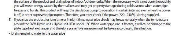
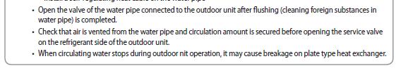
40 6. Installation and Service Precautions - If you do not perform nitrogen flushing when welding the pipes, oxide may form inside the pipes and cause damage to parts such as the compressor and valves. - Adjust the flow rate of the nitrogen flushing with a pressure regulator to maintain 0.05m3/h or less. - Before welding the pipes on the connection port, cover the valve with a wet cloth. (to protect the parts within the valve).
41 Installation Checklist Category Check Item Detailed Contents Check Result Specifications Installation status Refrigerant part Water part Installation / service space Checking the checklist when installing the product Is the minimum distance from the hydro unit kept? Front side: 60 cm Back side: 10 cm Left side: 30 cm Right side: 40 cm Top : 10 cm Yes ( ), No ( ) Is the checklist checked? Checked ( ), Not checked ( ) Levelling Is the level of the hydro unit less than 5º? Yes( ), No ( ) Installation location Repairing the product The product is placed level and at an angle from the floor is less than 5? 1) Make sure there are no oil residue,, sulfurous fumes, nor inflammable gases.. 2) Make sure there are no fine powders, noises nor vibrations. Are the dustproof frame or rubbers installed? (Recommended) Yes( ), No ( ) Detailed installation location:. Yes ( ), No( ) The minimum distance for service should be kept. The product should be installed level at an angle from the floor less than 5. Please review the proper location for installation in the installation manual. E.g. Installing in a basement machinery room Pipe installation ti The total t length of the water inlet and outlet t pipes should Is the length of the water pipe less than 90m.? Yes( ), No ( ) specifications be less than 90m. Does the insulation material for the refrigerant pipe satisfy the following: Thickness : Liquid pipe insulation 9 mm Yes ( ), No ( ) 9mm or higher for fluid pipes and 25mm or more for gas Gas pipe insulation 25 mm Pipe insulation pipes? Is the material of the insulator either EPDM or NBR? Yes ( ), No( ) Pressure of the refrigerant Refrigerant leakage check Opening the refrig erant Water circulation flow rate Water pressure What is the pressure of the refrigerant after performing a 20 minute trial run? Is the gauge pressure in 10 minutes after the vacuum work kept at 5torr or lower? High pressure ( )kgf/cm2 Low pressure ( )kgf/cm2 Yes ( ), No ( ) ( )torr (MPa) Use After the vacuum work of the outdoor unit, the pressure should be kept 5torr or lower. Is the outdoor unit service valve open? Yes ( ), No( ) Theservicevalveshouldalwaysbeopen valve should always open. The flow rate should be at least 92LPM for 10HP and 150L Flow rate measured by flow meter ( )LPM PM for 16HP. Pressure of the inlet of the hydro unit ( )kgf/cm2 Record the pressure while performing a trial run. (2kgf/cm2 or higher is recommended.) Pressure of the outlet of the hydro unit ( )kgf/cm2 (The maximum allowed pressure is 10kgf/cm2.) Water Temperature of the inlet of the hydro unit ( ) Record the temperature while perfoming a trial run. temperature Temperature of the outlet of the hydro unit ( ) (45 or lower at the outlet is recommended.) d The water quality must satisfy the conditions for a cooling air-conditioning system. Pipe flushing Have the pipes been flushed before performing a trial run? Yes ( ), No ( ) Flush the pipes for at least 24 hours. Clean the strainer every 2 hours while flushing the pipes..
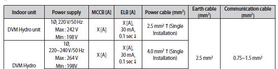
42 Installation Checklist Category Check Item Detailed Contents Check Result Specifications Mesh size ( ) mesh 50 mesh or higher should be used. Strainer Is the strainer installed in the proper location and direction? Yes ( ), No ( ) Install the strainer at the inlet of the hydro unit. Air vent Is the air vent installed at the top of the pipe? Yes ( ), No ( ) Install the air vent at the highest point of the pipe. Drain valve Is the drain valve installed? Yes( ), No ( ) Install a 15A or higher valve at the inlet of the hydro unit (at the lowest part) Shut-off valve Are the inlet and outlet shut-off valves installed? Yes( ), No ( ) Install the inlet and outlet shut-off valves. What type of the expansion tank is installed? Closed type ( ), Open type ( ) Closed expansion tank Expansion tank Upper part of the boiler (heat storage tank) Where is the expansion tank installed? (It is generally applied. Only if there is as tank, the location is not a problem.) Water part Use PE, Heatron, EPDM or NBR material. Pipe insulation Use 19T for 80A or lower and use 25T for 100A and Is the insulation material for water pipes properly Type of the insulation material ( ) higher. installed according to the specification. Thickness ( ) However, if there is a separate site facility specification, use the seperate site facility specifactions.. Check if there are no leaks using 1.5 times the Leakage check Are there any leaks? Yes ( ), No ( ) pressure of the standard operating pressure for 3 hours (if there is no standard of operating pressure, test using a pressure of 7kgf/cm2) Check if the pump works properly. Circulation pump Does the circulation pump work properly? Yes ( ), No ( ) (Check if water can pass and there are no abnormal noises. Check the flow switch meter.) 1) Power cable: Use H05RN-F / H07RN-F or higher. Are the thickness and length of the power cable Thickness ( ) mm2 2) Single phase model: Length of the power cable appropriate? Length ( )m 10m - 4.0mm2 10m < Length of the cable < 20m - 6.0mm2 Fix the power cable with the conduit of the Control Is the cable properly tied with the cable tie? Yes ( ), No ( ) Box or the cable tie. (The midnight and normal power cables should be firmly fixed.) Electricity Other Electric work If an error occurs, (check the display panels of the indoor unit main PCB and the wired remote control.) Differences from the standard drawing Type of conduit Are ring terminals used to connect the terminal block. Records the errors and measures taken Record differences Class 1flexible metal conduit( ) Flexible metal conduit covered with PVC ( ) Yes ( ), No ( ) Apply the class 1 flexible metal conduit or flexible metal conduit with PVC to the midnight and the normal power cables Apply the tightening torque to fasten the ring terminal (as shown in the installation manual) * M3 (communication cable F1, F2) N m * M4 (3-phase power cable) N m * M5(single-phase power cable) N m There should be no error or an appropriate measure should be taken. E.g. E606 error occurred. The communication cable has been reconnected.


43 7. Circuits Power supply and communication cable configuration Hydro Unit Hydro Unit HT Connecting power and communication cable Communication Terminal block Power Terminal block
44 7. Circuits DVM Hydro Unit Single-phase power DC power Communication Signal MAIN MICOM EEPROM: SUB PBA (Saving model option and address) 220V Power Power T/B EMI FILTER SMPS MAIN DCPower (12V and 5V) Sensor WATER IN, OUT Sensor EVA IN, OUT Sensor T/B Temperature Fuse Com munic ation T/B 485 Communication (Indoor and outdoor unit) 485 Communication: SUB PBA (Wired Remote Control) Thermostat DC Load Control AC Contact Load Control AC 24V AC 220V EEV Flow Switch External Control 3way_1 V/V 3way_2 V/V 2way V/V Defrost V/V Contact Load Control Booster Heater Main Pump Alarm Operation Check
45 7. Circuits DVM Hydro Unit HT Detection ZCP Water pump, External contactor EEV Temperature detection circuit EVA, WATER Temp. Sensor NASA Communication NASA Communication NASA Communication Detection circuit Detection circuit Detection circuit Detection circuit Detection circuit Detection circuit T/B Temp. sensor Room sensor Detection circuit High/Low pressure sensor


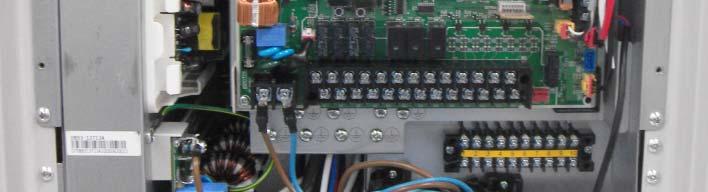
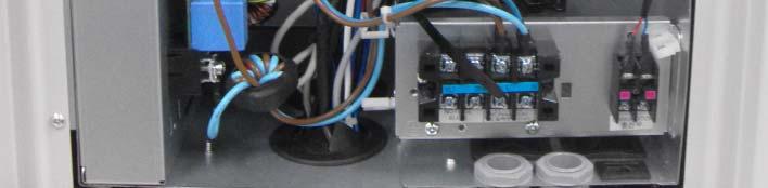
46 7. Circuits Control Box Parts Layout Drawing of C-BOX Picture of C-BOX


47 7. Circuits Hydro Unit HT Control Box Inner Parts Layout Drawing of C-BOX 회로도 _Single 회로도 _3 phase Picture of C-BOX


48 7. Circuits Removable EEPROM EEPROM SUB PBA For easier service, EEPROM has been designed as a SUB PBA. : Since the remote control option information is saved in the EEPROM, the option information does not need to be inputed again when replacing the board. If the Main PBA is defective and needs to be replaced: -Replace the Main PBA. - Install the previous EEPROM SUB PBA onto the new MAIN PBA. - Downloading data to the EEPROM is not necessary. If the EEPROM SUB PBA is defective: - Do not replace the MAIN PBA. - Replace the EEPROM SUB PBA with a new one. - Download the latest EEPROM data from the PRMS server. - Write the data onto the EEPROM using the Air Kit. (Refer to the Air Kit manual.) EEPROM data file naming convention of the PRMS server: [code]_[model]_[version].src

 : While the previous DVM indoor unit had")


49 Removable 4WIRE COMM PBA 7. Circuits 4WIRE COMM SUB PBA PBA for communication with the wired remote control (4 wire) : While the previous DVM indoor unit had built-in wired remote control communication circuit on the main PBA, the new circuit is designed as a sub PBA in the DVM hydro unit extending functionality. Troubleshooting wired remote control communications failure 1. Check if the 4WIRE COMM SUB PBA is properly inserted. 2. Measure the resistance of the pins of the communication IC on the 4WIRE COMM SUB PBA (in the same way as checking the communication problem of the indoor unit PBA.) - After the measurement, if the communication IC is defective, replace the SUB PBA. - After the measurement, if the communication IC is normal, replace the wired remote control.


50 7. Circuits Connecting External Contacts Hydro Unit Hydro Unit HT


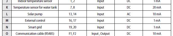
51 Connecting External Contacts 7. Circuits


52 Connecting External Contacts 7. Circuits
53 7. Circuits Water Pump and Booster Heater Connections Water pump Booster heater A dry contact type and the connection with an external power source is necessary. : DVM HYDRO UNIT/HYDRO UNIT HT only provides a contact signal necessary to drive the device. A dry contact type and a connection with an external power source is necessary. :DVMHYDROUNIT/HYDRO UNIT HT only provides a contact signal necessary to drive the device.


54 3-way and d2-way valve Connections 7. Circuits 3-way valve 2-way valve A wet contact type and the PBA provides the power. :Supports AC 220V of 0.5A or less. A wet contact type and the PBA provides the power. : Supports AC 220V of 0.5A or less.


55 7. Circuits Thermostat t and Solar Pump Thermostat Solar Pump Either type (AC230V, AC24V) can be used as a Thermostat. : When installing the unit, only one type of the thermostat should be connected. The maximum allowed current is 10mA or lower. Power should not be supplied to the input terminal for detection (contact signal).


56 7. Circuits Switch and Error Codes


57 7. Circuits Switch and Error Codes
58 8. External Contacts Point / Indoor Unit Control Flow External Contacts Control Operation Indoor unit on signal Pump is turned on. If the air conditioner operation signal is input Pump is turned on Flow switch is detected Indoor unit is turned on in order. Even while the system is operating, if the flow switch is turned off, the indoor unit stops. Flow switch If the Flow Switch is not detected. E911 Indoor unit is turned on. If the Flow Switch is normally detected. d
59 9. Diagnosis Checklist Meanings of First Alphabetical Character/Number of Error Code
60 9. Troubleshooting Error Codes
61 Error Codes 9. Troubleshooting
62 Error Codes 9. Troubleshooting
63 9. Troubleshooting E201 Communication Error between Indoor and Outdoor Units Check if the number of indoor units set in the DIP switches on the PCB of the outdoor unit is the same as that of the actually installed indoor units. Is the number of No. indoor units set in the DIP switches on the PCB of the outdoor unit the same as that of the actually installed indoor units? Yes Press the reset key (K3) of the outdoor PCB, and check the display module to check for the quantity of indoor units that respond to the tracking. Set the switches on the PCB of the outdoor unit to the number of the actually installed indoor units and press Reset key (K3) of the PCB of the outdoor unit to re-execute execute tracking. Is there no sign of the indoor response on the display during tracking? No. Yes Remove the communication cable which connects the outdoor unit to the indoor unit, and measure the 2 cables of the outdoor unit with an oscilloscope. Is sthe voltage otagebetween ee the 2 cables a square wave with DC±0.7V or more? Yes No. Check the communication cable which connects the outdoor unit to the indoor unit. If there is no abnormality, then connect the indoor units one by one to find the indoor unit that is interfering with the communication for inspection and change the indoor unit PCB. After 2 minutes, find the indoor unit which displays the communication error for the indoor units, and check for overlaps in the PCB address setup. (If the indoor unit addresses are overlapped, then a communication error will occur). - In this case, a communication error will occur in every indoor unit (two or more units) with the address incorrectly set. If there is no abnormality in the address, check the communication cable and change the indoor unit PCB. Check the communication cable and the connector of the outdoor unit PCB, and change the PCB.
64 9. Troubleshooting E202 Communication Error between Indoor and Outdoor Units after Tracking Press the reset key (K3) of the outdoor unit PCB and check the display module. Is there no indoor unit response at all from the display module during the tracking? Yes Remove the communication cable that connects the outdoor unit to the indoor nit, and measure the 2 outdoor unit cables with a oscilloscope. No After two minutes, find the indoor unit which displays the communication error and check if the PCB address settings are overlapped. (Communication error occurs if the indoor unit addresses are overlapped.) -In this case, the communication error will occur in every indoor unit (2 or more units) with the address incorrectly set. Is the voltage between the 2 cables a square wave with DC±0.7V or more as shown in the image below? Yes No Connect the communication cable again to connect the outdoor unit to the indoor unit. Remove all the communication connectors on the PCB of the indoor unit, and connect them one by one to find the indoor unit which interferes with the communication to check and change the indoor unit PCB. If there is no abnormality in the address, check the communication cable and change the indoor unit PCB. Check the communication cable and the connector for the outdoor unit PCB, and change the PCB.
65 9. Troubleshooting E204 Communication Error between MCU and Outdoor Unit Check if the number of installed MCUs configured in the DIP switches on the PCB of the outdoor unit is the same as the number of actually installed MCUs. Is the number of installed MCUs configured No in the DIP switches on the PCB of the outdoor unit the same as the number of the actually installed MCUs? Yes Press the reset key (K3) of the outdoor unit PCB and check the display module to check the quantity of MCU which responds to tracking. Set the DIP switch on the PCB of the outdoor unit to the number of actually installed MCUs and press the Reset key (K3) of the outdoor unit PCB to re-execute tracking. No Is there any response from the MCU on the display module during the tracking? Yes Remove the communication cable which connects the outdoor unit to the MCU, and measure the 2 cables of the outdoor unit with a oscilloscope. Is the voltage between the 2 cables a square wave with DC±0.7V or more? Yes No No Check the communication cable which connects the outdoor unit to the MCU. If there is no abnormality, connect the MCUs one by one to find the MCU which interferes with the communication to check and change the MCU PCB. After two minutes, find the MCU which displays the communication error and check if the PCB address settings are overlapped. (A communication error occurs if the indoor unit addresses are overlapped.) -In this case, a communication error will occur in every MCU (2 or more units) with the address incorrectly set. If there is no abnormality in the address, then check the communication cable and change the MCU PCB. Change the communication cable and the connector of the outdoor PCB, and then change the PCB.


66 9. Troubleshooting E907 Heat exchanger freezing burst protection - If the Water Out temperature falls or the EVA In or Out temperature falls during cooling or defrost operation. Check the water flow. Does the water flow satisfy the recommended flow requirement? No PHE Yes Check the Water Out temperature. Check the pipe system of the water. (Pump, Strainer, Valves) Is the Water Out temperature higher than 3? No Yes Check the EVA In/Out temperature. -Check the defect of Water Out temperature-sensor. -Confirm that the Water In temperature is low. No Is EVA In/Out temperature below zero? Yes - Check the control status of EEV. - Check the EVA In/Out temperature-sensor. - Check the Water In temperature.


67 9. Troubleshooting E908/909 Heat Exchanger freezing/bursting prevention and bursting of Heat Exchanger Check the water flow. Does the water flow satisfy the recommended flow requirement? No Yes Check the pipe system of the water. (Pump, Strainer, Valves) PHE Check the Water Out temperature. Is Water Out temperature higher than 3? No Yes -Check if the Water Out temperature-sensor is defective. - Confirm that the Water In temperature is low. Check the EVA In/Out temperature. No Is EVA In/Out temperature below zero? Yes -Check the control status of EEV. -Check the EVA In/Out temperature sensor. -Check the Water In temperature.

68 9. Troubleshooting E910 Breakaway of Water Out temperature-sensor. - Check in the heating and the cooling trial run states. If the difference between the Water Out is less than 2, this error occurs. Tw2_i Tw2_o <2 Check the mounting status of the Water Out temperature-sensor. Are the Water Out temperature sensor and the sensor holder accurately mounted? Yes No Reconnect the sensor and reinstall the sensor holder. Is the Water Out temperature-sensor's resistance value normal? (Refer to the table of resistance value) No Sensor defective: Replace the sensor Yes No During the Indoor Unit operation, was there a change in the Water Out temperature? Yes -Check if the Outdoor Unit is working properly. - Check if the refrigerant is clogged. End

 Are the Flow Switch and the PCB properly connected?")


69 9. Troubleshooting E911/913 Check the connection status of the Flow Switch. Breakaway of Water Out temperature- sensor - Pump signal output: If the Flow Switch signal is not detected within 5 seconds, this error occurs. - The signal detection is repeated six times. - (E913: Restart failure) Are the Flow Switch and the PCB properly connected? Yes No Reconnect the Flow Switch and then restart it. Flow Switch After disassembling the Flow Switch, check the junction-point signal of the Paddle operation. Is the junction-point formed? No Yes Replace the Flow Switch. Check the water flow. Does the water flow satisfy the recommended flow requirement? No Yes Check the pipe system of the water. (Pump, Strainer, Valves, etc.) Replace the PCB and then restart it.


70 9. Troubleshooting E914 Thermostat Wiring Error - If both heating and cooling signals are simultaneously input to the terminals of the thermostat on the PBA. - Use only one of the 230V or 24V terminal types. Do not use both types, otherwise, an error occurs. Flow Switch Check the wiring of the thermostat. Is the thermostat wired to both 230V and 24V? Yes Use only one wiring type of either 230V or 24V. Do not use both types. No Check if both the cooling and the heating wire hav been connected to each of the thermostat V Thermostat C N H N Cooling Heating C N H N 24V Thermostat Cooling Heating

 Centre")
71 10. References - Wired Remote Control Wired Remote Control for Water Heating (common with HT) Centre Control: +


72 10. References - Wired Remote Control Wired Remote Control for Water Heating (common with HT)


73 Wired Remote Control for Installation / Service mode
 BACnet On/Off")
74 10. References - Wired Remote Control Device Compatibilty S-NET3 DMS2 I/M DVM Hydro Unit MWR-WW00NWW00N (Dedicated wired remote control) BACnet On/Off Controller
SAC Technical Data Book
 SAC Technical Data Book Accessories Book for Global 1. MCU (Mode Control Unit) 2. EEV (Electronic Expansion Valve ) kit 3. AHU (Air Handling Unit) kit 4. FCU (Fan Coil Unit) Kit 5. UCK (Universal Communication
CHILLER Technical Data Book DVM CHILLER for Europe (R410A, 50/60Hz, HP)
") CHILLER Technical Data Book DVM CHILLER for Europe (R41A, 5/6Hz, HP) Model : AG42/56/7KSV NH/EU History Version Modification Date Remark Ver.1. Release DVM Chiller(pump integrated) TDB for Europe 16. 5.
CHILLER Technical Data Book DVM CHILLER for Europe (R41A, 5/6Hz, HP) Model : AG42/56/7KSV NH/EU History Version Modification Date Remark Ver.1. Release DVM Chiller(pump integrated) TDB for Europe 16. 5.
DVM S Universal Communication Kit (UCK) Design Guide
 Design Guide") DVM S Universal Communication Kit (UCK) Design Guide MCM-D211UN MXD-A24K100E MXD-A32K100E MXD-A40K100E MXD-A64K100E Version 11192018 Definition of Universal Communication Kit Technical Specification AHU
DVM S Universal Communication Kit (UCK) Design Guide MCM-D211UN MXD-A24K100E MXD-A32K100E MXD-A40K100E MXD-A64K100E Version 11192018 Definition of Universal Communication Kit Technical Specification AHU
SERVICE Manual SYSTEM AIR CONDITIONER INDOOR UNIT GH052EAM GH070EAM OUTDOOR UNIT UH052EAMT UH070EAMT. 1. Product Specifications
 SYSTEM AIR CONDITIONER INDOOR UNIT GH052EAM GH070EAM OUTDOOR UNIT UH052EAMT UH070EAMT SERVICE Manual SYSTEM AIR CONDITIONER CONTENTS 1. Product Specifications 2. Disassembly and Reassembly 3. Set Up the
SERVICE Manual FREE JOINT MULTI AIR CONDITIONER
 FREE JOINT MULTI AIR CONDITIONER INDOOR UNIT MH020FPEA MH023FPEA MH026FPEA MH035FPEA MH052FPEA MH8VP2-09 MH9VP2-07 MH9VP2-2 MH026FKEA MH035FKEA MH052FDEA OUTDOOR UNIT MH8VP2X MH9VP2X MH052FXEA2 MH068FXEA4
Submitted to Reference Approval Construction Unit Designation Schedule #
 Page 1of Job Name Location Purchaser Engineer Submitted to Reference Approval Construction Unit Designation Schedule # System Performance Power Indoor Units Modules Connected US Ton (nominal) Capacity
AIR CONDITIONER. Model : 1. Precautions. 2. Product Specifications. 3. Disassembly and Reassembly. 4. Troubleshooting. 5.
 SYSTEM AIR CONDITIONER Model : INDOOR UNIT AC012MNADCH/AA AC018MNADCH/AA AC024MNADCH/AA AC030MNTDCH/AA AC036MNTDCH/AA OUTDOOR UNIT AC012KXADCH/AA AC018JXADCH/AA AC024JXADCH/AA AC030JXADCH/AA AC036JXADCH/AA
AIR CONDITIONER OUTDOOR UNIT AM036NXMDCR AM048NXMDCR AM053NXMDCR AM060NXMDCR. Product Specifications. Disassembly and Reassembly
 SYSTM AIR CONDITIONR OUTDOOR UNIT AM036NXMDCR AM048NXMDCR AM053NXMDCR AM060NXMDCR AIR CONDITIONR CONTNTS Product Specifications Disassembly and Reassembly Refrigerant pipe installation Troubleshooting
Hydro Kit (For Medium Temperature) SVC MANUAL(Exploded View)
 SVC MANUAL(Exploded View)") Internal Use nly http://biz.lgservice.com Hydro Kit (For Medium Temperature) SVC MANUAL(Exploded View) MDEL : ARNH10GK2A2 / ARNH04GK2A2 CAUTIN Before Servicing the unit, read the safety precautions in
Internal Use nly http://biz.lgservice.com Hydro Kit (For Medium Temperature) SVC MANUAL(Exploded View) MDEL : ARNH10GK2A2 / ARNH04GK2A2 CAUTIN Before Servicing the unit, read the safety precautions in
Part 5. Troubleshooting. 1. Normal Air Conditioner Phenomenon Air Conditioner Protection in Common
 Part 5 1. Normal Air Conditioner Phenomenon... 1611 2. Air Conditioner Protection in Common... 1611 3. Malfunction Code and... 162 160 1. Normal Air Conditioner Phenomenon 1.1 When outdoor unit appears
Air Conditioner installation manual
 Air Handling Unit Application Kit MXDK025AN MXDK050AN MXDK075AN MXDK100AN MXDX000AN Air Conditioner installation manual imagine the possibilities Thank you for purchasing this Samsung product. EN DB6803711A04
AIR CONDITIONER 4 WAY CASSETTE SERIES. 1. Precautions. 2. Product Specifications. 3. Disassembly and Reassembly. 4. Troubleshooting. 5.
 SYSTEM AIR CONDITIONER 4 WAY CASSETTE SERIES Model : INDOOR UNIT AC018JN4DCH/AA AC024JN4DCH/AA AC030JN4DCH/AA AC036JN4DCH/AA AC042JN4DCH/AA AC048JN4DCH/AA OUTDOOR UNIT AC018JXADCH/AA AC024JXADCH/AA AC030JXADCH/AA
Part 3 Troubleshooting
 Part Troubleshooting What is in this part? This part contains the following chapters: Chapter See page Troubleshooting 2 Error Codes: Hydro-box 7 Error Codes: Outdoor Units Error Codes: System Malfunctions
Submitted to Reference Approval Construction Unit Designation Schedule #
 Page 1of5 Job Name Location Purchaser Engineer Submitted to Reference Approval Construction Unit Designation Schedule # System Performance Modules Connected US Ton (nominal) Capacity (Btu/h) System Specifications
EHS. EHS (Mono, LT, 50Hz)
") EHS EHS (Mono, LT, 50Hz) I. Products 1. Nomenclature.... 5 2. Line-up....... 7 1. Specification...... 9 2. Capacity Tables..... 13 3. Dimensional Drawings............. 19 4. Piping Diagrams..... 23 5.
EHS EHS (Mono, LT, 50Hz) I. Products 1. Nomenclature.... 5 2. Line-up....... 7 1. Specification...... 9 2. Capacity Tables..... 13 3. Dimensional Drawings............. 19 4. Piping Diagrams..... 23 5.
Air-to-Water Heat Pump (50Hz, R410A) 5BPM0-01G (Replace: 5BPM0-01F)
 5BPM0-01G (Replace: 5BPM0-01F)") Air-to-Water Heat Pump (50Hz, R410A) 5BPM0-01G (Replace: 5BPM0-01F) P/No. : MFL66101106 CONTENTS Part 2. Design and installation Part 3. Accessories 1. Features 2. Nomenclature 3. List of functions 4.
Air-to-Water Heat Pump (50Hz, R410A) 5BPM0-01G (Replace: 5BPM0-01F) P/No. : MFL66101106 CONTENTS Part 2. Design and installation Part 3. Accessories 1. Features 2. Nomenclature 3. List of functions 4.
INSTALLATION MANUAL Duct Type Series MH FECA
 INSTALLATION MANUAL Duct Type Series MH FECA ENGLISH FRANÇAIS ESPAÑOL Free Joint Multi Air Conditioner (Cooling and Heating) E S F DB98-960A() Safety Precautions The following safety precautions must be
SUBMITTAL AG015KSVAJH/AA Samsung DVM Heat Pump Chiller. Submitted to Reference Approval Construction Unit Designation Schedule #
 Job Name Location Purchaser Engineer Submitted to Reference Approval Construction Unit Designation Schedule # Page 1 of 7 Performance Power Compressor 95 F Ambient, Entering Temperature: 54 F, Leaving
RC-54CA RO-50CA RC-54HA RO-50HA. SPLIT TYPE AIR CONDITIONER CASSETTE TYPE (50Hz) Indoor unit Outdoor unit
 Indoor unit Outdoor unit") SPLIT TYPE AIR CONDITIONER CASSETTE TYPE (50Hz) Indoor unit Outdoor unit RCW-54CB RO-50CA RC-54CA RO-50CA RC-54HA RO-50HA CONTENTS SPECIFICATIONS OUTLINE AND DIMENTIONS CIRCUIT DIAGRAM REFRIGERANT SYSTEM
SPLIT TYPE AIR CONDITIONER CASSETTE TYPE (50Hz) Indoor unit Outdoor unit RCW-54CB RO-50CA RC-54CA RO-50CA RC-54HA RO-50HA CONTENTS SPECIFICATIONS OUTLINE AND DIMENTIONS CIRCUIT DIAGRAM REFRIGERANT SYSTEM
YC ON-OFF SERIES. Service Manual
 YC ON-OFF SERIES Service Manual CONTENTS 1. Precaution... 3 1.1 Safety Precaution... 3 1.2 Warning... 3 2. Model Lists... 6 3. Dimension... 7 3.1 Indoor Unit... 7 3.2 Outdoor Unit... 11 4. Refrigerant
History List. Version Date Update Information New EHS SPLIT TDB Released. (Modify the Spec Note)
") History List Version Date Update Information 1.0 15.02.27-2015 New EHS SPLIT TDB Released. (Modify the Spec Note) 1.1 15.03.06 1.2 15.04.06 - Modify : Note(Spec, Capacity Table) / Electric Diagram / OD
History List Version Date Update Information 1.0 15.02.27-2015 New EHS SPLIT TDB Released. (Modify the Spec Note) 1.1 15.03.06 1.2 15.04.06 - Modify : Note(Spec, Capacity Table) / Electric Diagram / OD
Warning: 230V / 1ph / 50Hz V / 3ph / 50Hz. Remarks: Make sure that you have enough power. (See page 15 Cable table)
") 1 2 Warning: - Do not place your hand or any other objects into the air outlet and fan. It could damage the heat pump and cause injuries; - In case of any abnormality with the heat pump, cut off the power
1 2 Warning: - Do not place your hand or any other objects into the air outlet and fan. It could damage the heat pump and cause injuries; - In case of any abnormality with the heat pump, cut off the power
Air-to-Water Heat Pump (50Hz, R410A) 5BPM0-01J (Replace: 5BPM0-01H)
 5BPM0-01J (Replace: 5BPM0-01H)") Air-to-Water Heat Pump (50Hz, R410A) 5BPM0-01J (Replace: 5BPM0-01H) P/No. : MFL66101106 CONTENTS Part 2. Design and installation Part 3. Accessories 1. Features 2. Nomenclature 3. List of functions 4.
Air-to-Water Heat Pump (50Hz, R410A) 5BPM0-01J (Replace: 5BPM0-01H) P/No. : MFL66101106 CONTENTS Part 2. Design and installation Part 3. Accessories 1. Features 2. Nomenclature 3. List of functions 4.
SERVICE MANUAL MUZ-FH25VE MUZ-FH35VE MUZ-FH50VE OUTDOOR UNIT. No. OBH624. Models HFC. Revision A: MUZ-FH50VE- E1 has been added. Please void OBH624.
 SPLIT-TYPE AIR CONDITIONERS Revision A: MUZ-FH50VE- E1 has been added. Please void OBH624. OUTDOOR UNIT SERVICE MANUAL HFC utilized R410A. OBH624 REVISED EDITION-A Models MUZ-FH25VE MUZ-FH35VE MUZ-FH50VE
INSTALLATION MANUAL. System Air Conditioner (Cooling and Heating) Cassette Type Series CH070CAV1 CH105CAV CH140CAV DB A(1) ENGLISH ESPAÑOL
 Cassette Type Series CH070CAV1 CH105CAV CH140CAV DB A(1) ENGLISH ESPAÑOL") INSTALLATION MANUAL Cassette Type Series CH070CAV1 CH105CAV CH140CAV ENGLISH FRANÇAIS ESPAÑOL System Air Conditioner (Cooling and Heating) E S F DB98-30519A(1) Safety Precautions (Carefully follow the
INSTALLATION MANUAL Cassette Type Series CH070CAV1 CH105CAV CH140CAV ENGLISH FRANÇAIS ESPAÑOL System Air Conditioner (Cooling and Heating) E S F DB98-30519A(1) Safety Precautions (Carefully follow the
SERVICE Manual CASSETTE TYPE AIR CONDITIONER INDOOR UNIT KH026EAM KH035EAM OUTDOOR UNIT UH026EAM UH035EAM. 1. Product Specifications
 CASSETTE TYPE AIR CONDITIONER INDOOR UNIT KH026EAM KH035EAM OUTDOOR UNIT UH026EAM UH035EAM SERVICE Manual AIR CONDITIONER CONTENTS 1. Product Specifications 2. Disassembly and Reassembly 3. Block Diagrams
SERVICE MANUAL MUFZ-KJ50VE - E1, E2, ER1, ER2, ET1, ET2 MUFZ-KJ35VE OUTDOOR UNIT. No. OBH667. Models HFC
 Revision D: MUFZ-KJ25VE - E2, ER2, ET2, MUFZ- KJ35VE - E2, ER2, ET2 and MUFZ- KJ50VE - E2, ER2, ET2 have been added. Please void OBH667 REVISED EDITION-C. OUTDOOR UNIT SERVICE MANUAL HFC utilized R410A.
DUCT type. Большая библиотека технической документации каталоги, инструкции, сервисные мануалы, схемы.
 SPLIT TYPE AIR CONDITIONER (50Hz) DUCT type Models Indoor unit Outdoor unit RD-25CA RD-25HA RD-30CA RD-30HA RO-25CA RO-25HA RO-30CA RO-30HA C O N T E N T S SPECIFICATIONS.............................................
SERVICE MANUAL 42QHF009DS* 42QHF012DS* 42QHF018DS* 42QHF022DS* 38QUS009DS* 38QUS012DS* 38QUS018DS* 38QUS022DS* Indoor unit.
 SERVICE MANUAL Indoor unit Outdoor unit 42QHF009DS* 42QHF012DS* 42QHF018DS* 42QHF022DS* 38QUS009DS* 38QUS012DS* 38QUS018DS* 38QUS022DS* INDEX PART1 GENERAL INFORMATION PART2 ELECTRICAL DIAGRAM PART3 TROUBLE
INSTALLATION MANUAL RHF025EE Series RHF035EE Series RHF050EE Series RHF080EE Series RHF100EE Series
 INSTALLATION MANUAL RHF025EE Series RHF035EE Series RHF050EE Series RHF080EE Series RHF100EE Series PORTUGUÊS ENGLISH ITALIANO ESPAÑOL FRANÇAIS ERV (Energy Recovery Ventilator) DEUTSCH E S F I P D DB98-27512A(3)
SERVICE MANUAL MUZ-DM25VA - E1, ER1, ET1 MUZ-DM35VA - E1, ER1, ET1 OUTDOOR UNIT. No. OBH751. Models HFC R410A
 OUTDOOR UNIT SERVICE MANUAL HFC utilized R410A. Models MUZ-DM25VA - E1, ER1, ET1 MUZ-DM35VA - E1, ER1, ET1 Indoor unit service manual MSZ-DM VA Series (OBH750) CONTENTS 1. TECHNICAL CHANGES 2 2. PART NAMES
SERVICE MANUAL OFFICE PRO 36 SERIAL NUMBER FROM APRIL 2007 (0407) TO PRESENT. DocID: 00G00010EA
 TO PRESENT. DocID: 00G00010EA") SERVICE MANUAL OFFICE PRO 36 SERIAL NUMBER FROM APRIL 2007 (0407) TO PRESENT DocID: 00G00010EA 2008 DENSO SALES CALIFORNIA, INC. All rights reserved. This book may not be reproduced or copied, in whole
SERVICE MANUAL OFFICE PRO 36 SERIAL NUMBER FROM APRIL 2007 (0407) TO PRESENT DocID: 00G00010EA 2008 DENSO SALES CALIFORNIA, INC. All rights reserved. This book may not be reproduced or copied, in whole
Air Conditioner. user installation & manual manual. imagine the possibilities
 ARFSSSBWK Series ARFSSSCUR AJ JNADCH Series Air Conditioner user installation & manual manual This manual is made with 100% recycled paper. imagine the possibilities Thank you for purchasing this Samsung
4. Disassembly and Reassembly
 4. Disassembly and Reassembly Stop operation of the air conditioner and remove the power cord before repairing the unit. 4-1 Indoor Unit 4-1-1 MH FPEA /MH VP2-1 Front Panel 1) Stop the air conditioner
SERVICE MANUAL MUY-GL24NA - U1. No. OBH733. Models HFC. Revision B: REVISED EDITION-B R410A
 Revision B: MUZ-GL09NA- U8 and MUZ-GL09NAH- U8 have been added. Please void OBH733 REVISED EDITION-A. OUTDOOR INDOOR UNIT UNIT SERVICE MANUAL HFC utilized R410A. OBH733 REVISED EDITION-B Models MUZ-GL09NA
Westinghouse. Split System Inverter Series. Service Manual
 Westinghouse Split System Inverter Series Service Manual Model: WIWPK/WCHPK Range: 2.6kw 7.6kw CONTENTS 1. Precaution... 1 1.1 Safety Precaution... 1 1.2 Warning... 1 2. Function... 5 3. Dimension... 6
SERVICE MANUAL SPLIT WALL-MOUNTED TYPE MODELS MWCOHC30S/MRCOHC30AS MWCOHC36S/MRCOHC36AS
 SERVICE MANUAL SPLIT WALL-MOUNTED TYPE MODELS MWCOHC30S/MRCOHC30AS MWCOHC36S/MRCOHC36AS CONTENTS 1. Precaution... 1 1.1 Safety Precaution... 1 1.2 Warning... 1 2. Function... 6 3. Dimension... 7 3.1 Indoor
HEAT CONTROLLER, INC.
 HEAT CONTROLLER, INC. Wall Mounted Mini-Split System Single-Zone Air Conditioning/Heat Pump Service Manual(General) VMC09SB-1/VMH09SB-1 VMC12SB-1/VMH12SB-1 VMC18SB-1/VMH18SB-1 VMC24SB-1/VMH24SB-1 VMC30SB-1/VMH30SB-1
MULTI INVERTER SERIE H6M
 MULTI INVERTER SERIE H6M Service manual www.mundoclima.com Thank you very much for purchasing our products. Please read this manual carefully before installing and using the unit. ODMFI-B1-1606 CL20440
SERVICE MANUAL UNI SPLIT SERIES. ASC-xxBI, ASD-xxBI, ASF-xxBI, ASGE-xxBI, ASGE-xxBI-3
 EN SERVICE MANUAL UNI SPLIT SERIES ASC-xxBI, ASD-xxBI, ASF-xxBI, ASGE-xxBI, ASGE-xxBI-3 Original instructions IMPORTANT NOTE: Read this manual carefully before installing or operating your new air conditioning
Water cooled VRV IV W-series
 Water cooled VRV IV W-series Ideal for high rise buildings, using water as heat source Unified range for heat pump & heat recovery and standard & geothermal series 22 Indoor units VRV type indoor units
CASSETTE type SPLIT TYPE AIR CONDITIONER. (60Hz) AUU18RCLX AUU24RCLX AUU36RCLX AUU42RCLX AOU18RLX AOU24RLX AOU36RLX AOU42RLX CONTENTS.
 AUU18RCLX AUU24RCLX AUU36RCLX AUU42RCLX AOU18RLX AOU24RLX AOU36RLX AOU42RLX CONTENTS.") SPLIT TYPE AIR CONDITIONER CASSETTE type (60Hz) Models Indoor unit AUU8RCLX AUURCLX AUU6RCLX AUURCLX Outdoor unit AOU8RLX AOURLX AOU6RLX AOURLX CONTENTS SPECIFICATIONS... DIMENSIONS... REFRIGERANT SYSTEM
SPLIT TYPE AIR CONDITIONER CASSETTE type (60Hz) Models Indoor unit AUU8RCLX AUURCLX AUU6RCLX AUURCLX Outdoor unit AOU8RLX AOURLX AOU6RLX AOURLX CONTENTS SPECIFICATIONS... DIMENSIONS... REFRIGERANT SYSTEM
Air Conditioner. installation manual. imagine the possibilities. Wired Remote Control MWR-WE10. Thank you for purchasing this Samsung product.
 Control MWR-WE10 Air Conditioner installation manual imagine the possibilities Thank you for purchasing this Samsung product. E S F I P D G R A DB98-32811A(2) Safety Information This installation manual
500 EX Fusion Compressor Series
 500 EX Fusion Compressor Series R404A M/T R404A L/T Capacity RANGE 13.8kW - 20.4kW 7.7kW -11.2kW Copeland Fusion Semi-Hermetic Horizontal Scroll Compressors For Medium and Low Temperature Applications
WALL MOUNTED type SPLIT TYPE ROOM AIR CONDITIONER CONTENTS. Models
 SPLIT TYPE ROOM AIR CONDITIONER WALL MOUNTED type Models Indoor unit ASY9USCCW ASY9USCCW ASY12USCCW Outdoor unit AOY9USCC AOY9UFCC AOY12USCC CONTENTS SPECIFICATIONS................................... 1
MCU. installation manual. imagine the possibilities DB A-06 EN ZH MCU-S6NEE1N MCU-S4NEE1N MCU-S4NEE2N MCU-S2NEK1N
 -S6NEE1N -S4NEE1N -S4NEE2N -S2NEK1N installation manual This manual is made with 100% recycled paper. imagine the possibilities Thank you for purchasing this Samsung product. EN ZH DB68-03490A-06 Contents
Samsung EHS, XL Range of Commercial Air to water heat pumps
 Samsung EHS, XL Range of Commercial Air to water heat pumps 2018 Freedom Heat Pumps Spec and price Guide Samsung is moving with, and ahead of, our customers Put simply, our differentiation is centered
Air Conditioner. installation manual. imagine the possibilities. DVM S WATER-GEO AM HXWA Series EN ES FR PT DB A-00
 DVM S WATER-GEO AM HXWA Series Air Conditioner installation manual This manual is made with 100% recycled paper. imagine the possibilities Thank you for purchasing this Samsung product. EN ES FR PT DB68-04799A-00
SERVICE MANUAL CLASSIC PLUS 26 SERIAL NUMBER FROM JANUARY 2009 (0109) TO PRESENT. DocID: 00G00025E
 TO PRESENT. DocID: 00G00025E") SERVICE MANUAL CLASSIC PLUS 26 SERIAL NUMBER FROM JANUARY 2009 (0109) TO PRESENT DocID: 00G00025E 2009 DENSO SALES CALIFORNIA, INC. All rights reserved. This book may not be reproduced or copied, in whole
SERVICE MANUAL CLASSIC PLUS 26 SERIAL NUMBER FROM JANUARY 2009 (0109) TO PRESENT DocID: 00G00025E 2009 DENSO SALES CALIFORNIA, INC. All rights reserved. This book may not be reproduced or copied, in whole
SERVICE MANUAL OUTDOOR UNIT MUZ-FH06NAH MUZ-FH09NAH MUZ-FH06NA MUZ-FH09NA MUZ-FH09NA - 1 MUZ-FH09NAH - 1 MUZ-FH12NA MUZ-FH12NAH
 Revision D: Capacity corrections have been corrected [7-1. 2), 3)]. OBH684 REVISED EDITION-C is void. OUTDOOR UNIT SERVICE MANUAL HFC utilized R410A. OBH684 REVISED EDITION-D Models MUZ-FH06NA MUZ-FH09NA
SYSTEM AIR CONDITIONER
 SYSTEM AIR CONDITIONER AHU SERIES Model : INDOOR UNIT AC018KNZDCH/AA AC024KNZDCH/AA AC030KNZDCH/AA AC036KNZDCH/AA AC042KNZDCH/AA AC048KNZDCH/AA AC054KNZDCH/AA OUTDOOR UNIT AC018JXADCH/AA AC024JXADCH/AA
Air to water heat pump
 Document 1589-3 ~ 04/03/2013 Air to water heat pump FR EN Split System (single phase type) Hydraulic unit WS *A050DD6 WS *A100DD6 WG *A050DD6 WG *A100DD6 Outdoor unit WO *A060LDC WO *A080LDC WO *A100LDT
Advance Split
 Engineering Data Manual Aqu@Scop Advance Split Air-to-Water DC Inverter Split Heat Pumps Models 005, 008, 012 & 014 2 to 16 kw Strength Points Most efficient heating technology with variable speed compressor.
AIR-CONDITIONER TOSHIBA SERVICE MANUAL SPLIT TYPE, HEAT PUMP COOLING ONLY FILE NO. A Tel: Fax:
 Tel: 08 0 www.heronhill.co.uk Fax: 08 80 TOSHIBA Heronhill - for all your Toshiba requirements FILE NO. A90-00 SERVICE MANUAL AIR-CONDITIONER SPLIT TYPE, HEAT PUMP COOLING ONLY WAY CASSETTE TYPE RAV-0TUH--PE
F SERIES ON-OFF SERIES. Service Manual 2016
 F SERIES ON-OFF SERIES Service Manual 2016 CONTENTS 1. Precaution... 3 1.1 Safety Precaution... 3 1.2 Warning... 3 2. Function... 6 3. Dimension... 7 3.1 Indoor Unit... 7 3.2 Outdoor Unit... 9 4. Refrigerant
Dunham Bush Air Cooled Screw Chiller AFVX B 6SR Series
 Dunham Bush Air Cooled Screw Chiller AFVX B 6SR Series Type of Compressors Compressor Rotary Scroll Reciprocating Screw Centrifugal Air Cooled Chiller 77 ~ 329TR (270 ~ 1156 kw) ACDX Series 100 ~ 520TR
CASSETTE type INVERTER MULTI AIR CONDITIONER. Models AUY12LBAB AUY14LBAB AOY18LMAK2
 INVERTER MULTI AIR CONDITIONER CASSETTE type Models Indoor unit AUY12LBAB AUY14LBAB Outdoor unit AOY18LMAK2 CONTENTS SPECIFICATIONS..................... 1 OUTLINE AND DIMENSIONS........... 2 REFRIGERANT
SERVICE MANUAL. No. OBH747 REVISED EDITION-A. Models HFC
 Revision A: MUZ-HM09/12NA- U8, MUZ-HM09/12NA2- U8, MUZ-HM15/18NA- U1, MUZ-HM15/18NA2- U1 and MUZ-HM24NA2- U1 have been added. Please void OBH747. OUTDOOR INDOOR UNIT UNIT SERVICE MANUAL HFC utilized R410A.
FROZEN SERIE SERVICE MANUAL. DC Inverter R32. Sistemi per la climatizzazione
 DC Inverter R32 Sistemi per la climatizzazione SERVICE MANUAL FROZEN SERIE CONTENTS 1. General information of Outdoor Units... 3 2. Features... 4 3. Dimensions... 5 4. Refrigeration Cycle Diagram... 6
Owners Manual UA75 TO UA1200 SERIES Refrigerated Air Dryer
 1 Owners Manual UA75 TO UA1200 SERIES Refrigerated Air Dryer DESCRIPTION PAGE INTRODUCTION 2 INSTALLATION 3 INSTALLATION GUIDE 4 DRYER CONTROLS 5 DRYER CONTROLS AND SAFTEY SHUTDOWNS 6 START UP 6 INITIAL
DOLPHIN RADIATOR & COOLING SYSTEMS P.O.Box: 1424,Ph#: , Fax#: ,
 DOLPHIN RADIATOR & COOLING SYSTEMS P.O.Box: 1424,Ph#: +971-6-5432526, Fax#: +971-6-5432415, Email: dolcool@emirates.net.ae, web site: www.dolphinheattransfer.com NOMENCLATURE: INTRODUCTION DOLCOOL branded
DLCLRA. INSTALLATION INSTRUCTIONS Outdoor Unit Single Zone Ductless System Sizes 36 to 58 TABLE OF CONTENTS
 DLCLRA INSTALLATION INSTRUCTIONS Outdoor Unit Single Zone Ductless System Sizes 36 to 58 Fig. 1 - Size 36 TABLE OF CONTENTS PAGE SAFETY CONSIDERATIONS... 2 PARTS LIST... 3 SYSTEM REQUIREMENTS... 4 WIRING...
TOSHIBA Carrier (UK) Ltd. LC DX Interface Installation manual ENGLISH. For commercial use. Model name:
 Ltd. LC DX Interface Installation manual ENGLISH. For commercial use. Model name:") TOSHIBA Carrier (UK) Ltd. LC DX Interface Installation manual Model name: For commercial use RAV-DXC010 LC DX Interface ENGLISH Please read this carefully before installing the LC DX interface. This Manual
TOSHIBA Carrier (UK) Ltd. LC DX Interface Installation manual Model name: For commercial use RAV-DXC010 LC DX Interface ENGLISH Please read this carefully before installing the LC DX interface. This Manual
EEE Yönetmeliğine Uygundur This EEE is compliant with RoHS
 EEE Yönetmeliğine Uygundur This EEE is compliant with RoHS ADN BDE Series AM FNBD Series AM FNBF Series DVM Hydro unit / Hydro unit HT installation manual This manual is made with 100% recycled paper.
HT V2 HT Split
 Scroll compressor Refrigerant R07C Aqu@Scop HT V Aqu@Scop HT Split High Temperature Air-to-Water Heat Pumps Models -, -7 and 8-9.0 to 7.9kW Aqu@Scop HT V / Aqu@Scop HT Split Installation examples - Single
AirtoWaterHeat Pump -TDM PLUS Hydro Unit
 AirtoWaterHeat Pump -TDM PLUS Hydro Unit Installation manual AE090MNYDEH / AE090MNYDGH / AE160MNYDEH / AE160MNYDGH Thank you for purchasing this Samsung air conditioner. Before operating this unit, please
Installation, Operation & Maintenance
 Installation, Operation & Maintenance Contura 5G Series R410a High Ambient & High Efficiency MS-SVX041A-EN 1 Contents 1. Precaution 1.1 Safety Precuation 03 1.2 Warning 03 2. Product Specifications 06
OIL COOLER INSTRUCTION HANDBOOK
 OIL COOLER INSTRUCTION HANDBOOK INDEX 1. GENERALITY 2 1.1 OPERATING RANGE 1.2 IMPORTANT 2. INSTALLATION 3 2.1 TRANSPORTATION 2.2 INSTALLATION LOCATION 2.3 PIPING 2.4 WIRING (see the electrical diagram
Fast Track Troubleshooting
 Fast Track Troubleshooting Model: RH22** Bulletins: IMPORTANT SAFETY NOTICE For Technicians Only This service data sheet is intended for use by persons having electrical, electronic, and mechanical experience
DC INVERTER MULTI-SYSTEM AIR CONDITIONER
 TECHNICAL & SERVICE MANUAL OUTDOOR UNIT : CLM97 CLM7 CLM7 FILE NO. Destination: North America DC INVERTER MULTI-SYSTEM AIR CONDITIONER Capacity at 0V 9,700 BTU/h,00 BTU/h 0,600 BTU/h Outdoor Model No.
Container Refrigeration
 Container Refrigeration OPERATION AND SERVICE for 69NT40-561-019 Evergreen Container Refrigeration Units Table 3 6 Controller Alarm Indications (Sheet 1 of 8) AL03 Loss of Superheat Control AL05 Manual
Design guide for DVM Chiller. Design guide for DVM Chiller
 Design guide for DVM Chiller 1 Modification history Date Ver. Modifier Modified detail 30 May 17 1.0 Junho Lim - New 23 Mar 18 1.5 F Weddington - North American Market 27 Mar 18 1.6 J McCloskey - Table
SPLIT TYPE ROOM AIR CONDITIONER CEILING TYPE (60Hz)
") SPLIT TYPE ROOM AIR CONDITIONER CEILING TYPE (60Hz) Indoor unit MS6YF Outdoor unit MR6YF CONTENTS SPECIFICATIONS... OUTLINE AND DIMENSIONS... REFRIGERANT SYSTEM DIAGRAM.... CIRCUIT DIAGRAM... INDOOR PCB
SPLIT TYPE ROOM AIR CONDITIONER CEILING TYPE (60Hz) Indoor unit MS6YF Outdoor unit MR6YF CONTENTS SPECIFICATIONS... OUTLINE AND DIMENSIONS... REFRIGERANT SYSTEM DIAGRAM.... CIRCUIT DIAGRAM... INDOOR PCB
SM Field Installed Electric Heat Kit
 SM Field Installed Electric Heat Kit HK050 HK100 HK150 HK200 Installation Manual 8733822029 (2018/07) US 2 SM Series Electric Heat Installation Manual Data subject to change 07.2018 8733822029 Installation
SERVICE MANUAL CLASSIC 10 SERIAL NUMBER FROM FEBRUARY 2011 (0211) TO PRESENT. DocID: 00G00089E
 TO PRESENT. DocID: 00G00089E") SERVICE MANUAL CLASSIC 10 SERIAL NUMBER FROM FEBRUARY 2011 (0211) TO PRESENT DocID: 00G00089E 2012 DENSO SALES CALIFORNIA, INC. All rights reserved. This book may not be reproduced or copied, in whole
SERVICE MANUAL CLASSIC 10 SERIAL NUMBER FROM FEBRUARY 2011 (0211) TO PRESENT DocID: 00G00089E 2012 DENSO SALES CALIFORNIA, INC. All rights reserved. This book may not be reproduced or copied, in whole
OWNER S MANUAL. Models: AC110, AC125, AC150 made from 2003 through Proudly Made in the USA
 OWNER S MANUAL Models: AC110, AC125, AC150 made from 2003 through 2010 Proudly Made in the USA support@aquacomfort.com www.aquacomfort.com/service-and-support/ (888) 475-7443 Manufacturing High Quality,
Installation Manual AIR TO WATER HEAT PUMP. Hydro Unit HWS-804XWHM3-E HWS-804XWHT6-E HWS-804XWHT9-E HWS-1404XWHM3-E HWS-1404XWHT6-E HWS-1404XWHT9-E
 AIR TO WATER HEAT PUMP Hydro Unit Model name: HWS-804XWHM3-E HWS-804XWHT6-E HWS-804XWHT9-E HWS-1404XWHM3-E HWS-1404XWHT6-E HWS-1404XWHT9-E English Please read this carefully before installing the Air to
Small VRF system. for light commercial and home use SERVICE MANUAL
 Small VRF system for light commercial and home use SERVICE MANUAL CONTENTS 1. TEST RUN 1-1 EXECUTION PROCEDURE AND EXECUTION PRECAUTIONS... 01-01 1-2 TEST RUN METHOD... 01-03 1-2-1 Check Items Before
DC INVERTER MULTI-SYSTEM AIR CONDITIONER
 TECHNICAL & SERVICE MANUAL OUTDOOR UNIT : CU-3KE19NBU CU-4KE24NBU CU-4KE31NBU DC INVERTER MULTI-SYSTEM AIR CONDITIONER Capacity at 0V 19,100 BTU/h,200 BTU/h 30,600 BTU/h Outdoor Model No. CU-3KE19NBU CU-4KE24NBU
CHILLER. Operator s & Installation Manual
 CHILLER MODELS: CH1001-A Operator s & Installation Manual Release Date: August 9, 2002 Publication Number: 620914301 Revision Date: May 6, 2010 Revision: E Visit the IMI Cornelius web site at www.cornelius.com
Wired Remote Controller XK19 and Wireless Remote Controller YT1F
 and Wireless Remote Controller YT1F Owner's Manual Commercial Air Conditioners Thank you for choosing Commercial Air Conditioners, please read this owner s manual carefully before operation and retain
Installation Instructions
 40MBFQ Floor Console Ductless System Sizes 09 to 58 Installation Instructions TABLE OF CONTENTS PAGE SAFETY CONSIDERATIONS... 2 PARTS LIST... 3 SYSTEM REQUIREMENTS... 4 WIRING... 4 DIMENSIONS... 5 CLEARANCES...
OWNER S MANUAL. Vintage Signature Series models: AC750, AC1050, AC1100, AC1250, AC1500, AC1750. Proudly Made in the USA.
 OWNER S MANUAL Vintage Signature Series models: AC750, AC1050, AC1100, AC1250, AC1500, AC1750 Proudly Made in the USA support@aquacomfort.com 888-475-7443 Manufacturing High Quality, High Efficiency Heat
CEILING type (60Hz) SPLIT TYPE ROOM AIR CONDITIONER CONTENTS. Models
 SPLIT TYPE ROOM AIR CONDITIONER CONTENTS. Models") SPLIT TYPE ROOM AIR CONDITIONER CEILING type (60Hz) Models Indoor unit ABU6RSLX Outdoor unit AOU6RLX CONTENTS SPECIFICATIONS....................... OUTLINE AND DIMENSIONS............. REFRIGERANT SYSTEM
SPLIT TYPE ROOM AIR CONDITIONER CEILING type (60Hz) Models Indoor unit ABU6RSLX Outdoor unit AOU6RLX CONTENTS SPECIFICATIONS....................... OUTLINE AND DIMENSIONS............. REFRIGERANT SYSTEM
SERVICE MANUAL MUZ-D30NA / - MUZ-D36NA / - MUY-D30NA / - MUY-D36NA / - OUTDOOR UNIT. No. OBH502. Models HFC. Revision E: REVISED EDITION-E R410A
 Revision E: Capacity corrections have been corrected [7-1. 2), 3)]. OBH502 REVISED EDITION-D is void. OUTDOOR UNIT SERVICE MANUAL HFC utilized R410A. OBH502 REVISED EDITION-E Models MUZ-D30NA / - 1 / -
High Wall Split Systems Cool Only 9K - 12K - 18K - 24K. Auto. Auto. Fan Speed. Smart LCD Wireless Control. Auto Mode.
 HFC4 1 0 A 0-40V ~, 0Hz 1Ph High Wall Split Systems Cool Only 9K - 1K - 18K - 4K R-410A IAQ $ Auto Auto Fan Speed Timer s Easy Flexible Installation Smart LCD Wireless Control Auto Mode Auto Restart Easy
Unit Controller (UC8) Quick Reference Operation and Fault Diagnosis
 Quick Reference Operation and Fault Diagnosis") Unit Controller (UC8) Quick Reference Operation and Fault Diagnosis (To be read in conjunction with labels TZ243 (Air-to-Air) & TZ245 (Water-to-Air) Date: 20 October 2015 Issue: 1 Index 1. Introduction...
Unit Controller (UC8) Quick Reference Operation and Fault Diagnosis (To be read in conjunction with labels TZ243 (Air-to-Air) & TZ245 (Water-to-Air) Date: 20 October 2015 Issue: 1 Index 1. Introduction...
INVERTER 9-12 DC INVERTER 9 SF
 INVERTER 9-12 DC 1. TECHNICAL DATA: DESCRIPTION OF PARAMETERS INVERTER 9 SF INVERTER 9 HP INVERTER 12 SF INVERTER 12 HP Cooling capacity (1) (min / rated / max) kw 1.4/2.3/2.7 1.4/2.3/2.7 1.8/2.7/3.1 1.8/2.7/3.1
SERVICE MANUAL MUZ-D30NA MUZ-D30NA- U1 MUZ-D36NA MUZ-D36NA- U1 MUY-D30NA MUY-D36NA OUTDOOR UNIT. No. OBH502. Wireless type Models HFC R410A
 OUTDOOR UNIT SERVICE MANUAL HFC utilized R410A. OBH502 Wireless type Models MUZ-D30NA MUZ-D30NA- U1 MUZ-D36NA MUZ-D36NA- U1 MUY-D30NA MUY-D36NA Indoor unit service manual MSZ-D NA Series (OBH501) MSY-D
Installation Instructions
 40MBFQ Floor Console Ductless System Sizes 09 to 12 Installation Instructions TABLE OF CONTENTS PAGE SAFETY CONSIDERATIONS... 2 PARTS LIST... 3 SYSTEM REQUIREMENTS... 4 DIMENSIONS... 5 CLEARANCES... 5
V ~, 50Hz 1Ph. High Wall Split Systems Heat Pump 9K - 12K - 18K - 24K - 28K. Auto. Auto Fan Speed. Auto. Smart LCD Wireless Control.
 HFC4 1 0 A 0-40V ~, 0Hz 1Ph High Wall Split Systems Heat Pump 9K - 1K - 18K - 4K - 8K R-410A Compressor Super Quiet AMS Anti-dust Filters Auto Fan Speed Timer Functions Defrost Protection Smart LCD Wireless
Wired controller KJR-08B/BE. Run. Fault. TB Tot. Out. Query. Heat. Net-On. Turn-On Mode
 R0A (kw-0kw) 0Hz KJR-0B/BE is a human-machine interaction(hmi) used for the communication between chiller operator and main board on the chiller itself. The setting and operation order can be send to the
INVERTER WALL MOUNTED TYPE ROOM AIR-CONDITIONER (Split system, air to air heat pump type)
") TECHNICAL MANUAL & PARTS LIST DRAFT INVERTER WALL MOUNTED TYPE ROOM AIR-CONDITIONER (Split system, air to air heat pump type) SRK20ZD-S - 1 - INDOOR UNIT Model SRK20ZD-S OUTDOOR UNIT Model SRC20ZD-S REMOTE
TECHNICAL MANUAL & PARTS LIST DRAFT INVERTER WALL MOUNTED TYPE ROOM AIR-CONDITIONER (Split system, air to air heat pump type) SRK20ZD-S - 1 - INDOOR UNIT Model SRK20ZD-S OUTDOOR UNIT Model SRC20ZD-S REMOTE
SERVICE MANUAL CLASSIC PLUS 14 SERIAL NUMBER FROM JANUARY 2008 (0108) TO PRESENT. DocID: 00G00019E
 TO PRESENT. DocID: 00G00019E") SERVICE MANUAL CLASSIC PLUS 14 SERIAL NUMBER FROM JANUARY 2008 (0108) TO PRESENT DocID: 00G00019E 2008 DENSO SALES CALIFORNIA, INC. All rights reserved. This book may not be reproduced or copied, in whole
SERVICE MANUAL CLASSIC PLUS 14 SERIAL NUMBER FROM JANUARY 2008 (0108) TO PRESENT DocID: 00G00019E 2008 DENSO SALES CALIFORNIA, INC. All rights reserved. This book may not be reproduced or copied, in whole
System Air Conditioner (Cooling and Heating) E S F I D DB A(2) ENGLISH ESPAÑOL FRANÇAIS ITALIANO DEUTSCH
 E S F I D DB A(2) ENGLISH ESPAÑOL FRANÇAIS ITALIANO DEUTSCH") INSTALLATION MANUAL RVXVHT080G Series RVXVHT100G Series RVXVHT120G Series RVXVHT140G Series RVXFHT080G Series RVXFHT100G Series RVXFHT120G Series RVXFHT140G Series DEUTSCH ENGLISH ESPAÑOL FRANÇAIS ITALIANO
INSTALLATION MANUAL RVXVHT080G Series RVXVHT100G Series RVXVHT120G Series RVXVHT140G Series RVXFHT080G Series RVXFHT100G Series RVXFHT120G Series RVXFHT140G Series DEUTSCH ENGLISH ESPAÑOL FRANÇAIS ITALIANO
SERVICE MANUAL ROOM AIR CONDITIONER TAN/TAG-A28FWIS TAN/TAG-A32FWIS CONTENTS
 SERVICE MANUAL ROOM AIR CONDITIONER TAN/TAG-A28FWIS TAN/TAG-A32FWIS CONTENTS SPECIFICATION... 1 FUNCTIONS... 5 SERVICE FUNCTION EXPLANATION... 7 OPERATION DETAILS... 8 TROUBLESHOOTING GUIDE... 13 PERFORMANCE
Safety Precautions WARNING INSTALLING THE UNIT POWER SUPPLY LINE, FUSE OR CIRCUIT BREAKER
 DH40GZM_IM_E/O_5844 3/3/06 0:4 AM Page Safety Precautions The following safety precautions must be taken when using your air conditioner. WARNING Risk of electric shock Can cause injury or death. Disconnect
Service Manual. Room Air Conditioner Split Wall-Mounted Type. Applies to: HSG-09HRN1 HSG-12HRN1 HSG-18HRN1 HSG-24HRN1
 Service Manual Room Air Conditioner Split Wall-Mounted Type Applies to: HSG-09CRN1 HSG-12CRN1 HSG-18CRN1 HSG-24CRN1 HSG-09HRN1 HSG-12HRN1 HSG-18HRN1 HSG-24HRN1 NOTE: Please read this first before servicing
OWNER S MANUAL. Vintage Classic HEAT COOL models. Proudly Made in the USA
 OWNER S MANUAL Vintage Classic HEAT COOL models Proudly Made in the USA support@aquacomfort.com www.aquacomfort.com/service-and-support 888-475-7443 Manufacturing High Quality, High Efficiency Heat Pump
INSTALLATION AND USER MANUAL
 Swimming Pool Heat Pump Swimming Pool Heat Pump INSTALLATION AND USER MANUAL Thank you for choosing our product and trusting our company. This manual is to provide you with necessary information for optimal