User s Guide. CN606 / 612 AC Series & CN606 / 612 DC Series CONTRONAUTICS INCORPORATED. Table of Contents.
|
|
|
- Rosalyn Davidson
- 5 years ago
- Views:
Transcription


1 User s Guide SECTION Table of Contents Page SECTION 1 INTRODUCTION Description Features Models SECTION 2 RS-232 COMMUNICATIONS Description RS-232 Cable Connections RS-232 PC Screens Operating Protocol SECTION 3 INSTALLATION Unpacking Mounting Outline Dimensions Wiring the Power Circuit Changing Line Voltage Setting DC Power Input Sensor Placement SECTION 4 PARTS OF THE SCANNER CN606 / 612 AC Series & CN606 / 612 DC Series CONTRONAUTICS INCORPORATED P.O. 171, 31 Wilkins St. Hudson MA Tel. (978) Fax (978) Front of the Scanner Button Functions Back of the Scanner Temperature/Setpoint Display SECTION 5 SETUP AND OPERATION "RUN" Mode Functions Functions Description "FUNCTION SELECT" Mode Security Entering the Password Wiring RTD Models Wiring OC Models Thermocouple Ranges SECTION 6 SPECIFICATIONS
2 SECTION 1 INTRODUCTION 1.1 Description The CN600 Series is a second generation of industrial Monitors based on the field proven CN601 six zone temperature monitor/alarm system. Several models and options are available. The CN600 Series is a microprocessor based Scanner (AC or DC) which accepts signals from thermocouples or RTD's. In the basic unit, six zones are sequentially scanned with a selectable display rate of 1 to 40 seconds each. A single output relay is provided to indicate an alarm condition on any zone. The faceplate has been arranged to call attention to an alarm condition by flashing the main temperature display and indicating the zone in alarm with a flashing zone number display. To prevent alarm on startup, Lo alarm is not activated until enabled zones cross Lo alarm setpoint. DC models can operate in remote locations powered by a battery. The CN600 Series implements a security password to protect certain functions. 1.2 Features Six Zones or 12 Zones Adjustable Display Time Field Proven Zone Switching Temperature and Setpoint Monitoring Four Digit Display of Temperature 2 Digit Display of Zones 5 Amp Latching or Non-Latching Alarm Relay Standard Thermocouples [T,E,J,K,S,R,B,C] Extended Ranges Six or Twelve RTD Inputs (2 wire) Six (3 wire) Six Optional Independent Outputs Programmable Selection of HI, LO or HI/LO Alarms Password Protection Optional Inputs Other Than Thermometer 1/4 DIN Aluminum Box Splash Proof Face Plug-In I/O Terminals RS-232 Communication NOTE: Consult RS-232 Software for use of RS-232 Communications Models The following Models are available: TC1- Standard Input [40 Mv] TC2- Extended Range [70 Mv] - RTD Input 6 or 12 Zone AC Series (120/240 VAC) Model Number Description CN606TC1 6 Zone T/C CN606TC2 6 Zone T/C w/extended Range CN606RTD2 6 Zone RTD (2 Wire) CN606RTD2-C 6 Zone RTD (2 Wire) Copper CN612RTD2 12 Zone RTD (2 Wire) CN612RTD2-C 12 Zone RTD (2 Wire) Copper CN606RTD-3 6 Zone RTD (3 Wire) CN606RTD3-C 6 Zone RTD (3 Wire) Copper CN612TC1 12 Zone T/C CN612TC2 12 Zone T/C w/extended Range (Open Collector Option) CN606TC1-OC 6 Zone T/C CN606TC2-OC 6 Zone T/C w/extended Range CN606RTD-OC 6 Zone RTD (2 Wire) CN606RTD-OC-C 6 Zone RTD (2 Wire) Copper DC Series Model Number CN606TC1-DC CN606TC2-DC CN606RTD2-DC CN606RTD2-DC-C CN612RTD2-DC CN612RTD2-C-DC CN606RTD-3-DC CN606RTD-3-DC-C CN612TC1-DC CN612TC2-DC (9 to 36 VDC) Description 6 Zone T/C 6 Zone T/C w/extended Range 6 Zone RTD (2 Wire) 6 Zone RTD (2 Wire) Copper 12 Zone RTD (2 Wire) 12 Zone RTD (2 Wire) Copper 6 Zone RTD (3 Wire) 6 Zone RTD (3 Wire) Copper 12 Zone T/C 12 Zone T/C w/extended Range 3


3 SECTION 2 RS-232 COMMUNICATIONS 2.1 Description NOTE: Minimum requirements to run RS-232 software is a PC computer with Windows RS-232 PC Screens The following screen menus are provided: 1. SELECT PORT- Scans all available PC ports and indicates which port is connected to scanners. Up to ten Monitors can be connected in parallel to a single RS-232 communications port on a PC. Each scanner is assigned a serial number from 0 to 9. The computer uses these numbers to determine which scanner unit to address at a given time. A simple set of menus is provided in the software which allows the operator to change the settings of each connected scanner unit and display individual operating parameters. For users with advanced software capabilities, see Section 2.4 for an operating protocol. 2.2 RS-232 Cable Connections 2. MAIN MENU- Allows the following operations: RUN one unit display or two units simultaneously. 4 5


4 2.4 Operating Protocol for RS-232 Communications CONFIGURE UNIT allows individual unit type selection, including: T/C Type, Temperature Scale, Latching or Nonlatching Alarm, and Hi, Lo or Hi/Lo Alarm. SET SETPOINTS allows changes to individual unit Hi and Low Setpoints, scan time settings and allows zones to be enabled/disabled. The CN606 Scanner is designed with standard RS-232 three wire serial communication capabilities. Up to ten Monitors can be parallel connected to a single PC. The transmission line is held in tristate to avoid cross-talk between Monitors except when the computer addresses a specific scanner for communication. Configuration BAUD rate = 4800 Data bits = 8 Parity = N Stop = 1 ( or 2 on some computers) Communication software for the PC is written in Visual Basic. This software package has been created to operate on PC Windows 95 platform meeting the minimum requirements. Customers can communicate with CN606 Monitors through a PC by using the following protocol: Monitors will not initiate communication. The RS-232 Command Module (computer or similar device) must initiate. All communication is in ASCII format except Check Sum. Check Sum is generated by hexadecimal addition with carry of data string (one byte). To start communication, the Command Module must send alert code ASCII [L] hex 4C. This commands the Monitors to cease RS232 communication and listen for an ID Code. The Command Module then sends the Identification Number for the scanner that it needs to address, ASCII [0 to 9] hex 30 to 39. The identified scanner will then expect a command code. All the other Monitors on-line will wait for the next alert code. Command codes are divided into two groups: Group 1. Commands requesting data from the scanner: ASCII [A] hex 41 = Zones/ Alarms/ Scan time ASCII [M] hex 4D = Model/ Password/ ID#/ # of zones ASCII [S] hex 53 = Setpoints ASCII [T] hex 54 = Temperature 6 7
5 ASCII Zones/ Alarms/ Scan time 15 bytes 1 byte [binary] zones 1 to 6 [ ] = (3F h) 1 byte [binary] zones 7 to 12 [ ] = (3F h) 1 byte [binary] zones 1 to 6 Hi alarm [ ] = (3F h) 1 byte [binary] zones 7 to 12 Hi alarm [ ] = (3F h) 1 byte [binary] zones 1 to 6 Lo alarm [ ] = (3F h) 1 byte [binary] zones 7 to 12 Lo alarm [ ] = (3F h) 2 digit scan time + check sum ASCII Model/ Password/ ID#/ # of zones 13 bytes 4 digit model code 4 bytes 4 digit password 4 bytes 2 digit ID# 2 bytes 2 digit number of zones 2 bytes + check sum 1 byte ASCII Coded Setpoints 97 bytes 12 zones, 4 digits each zone [Lo setpoint] 48 bytes 12 zones, 4 digits each zone [Hi setpoint] 48 bytes + check sum 1 byte ASCII Coded Temperature 49 bytes 12 zones, 4 digits each zone 48 bytes + check sum 1 byte Group 2. Commands preparing scanner to receive data: ASCII [m] hex 6D = Model/ Password/ ID# ASCII [e] hex 65 = Zone enable/ Scan time ASCII [s} hex 73 = Setpoints ASCII Model/ Password/ ID# 10 bytes 4 digit model code 4 bytes 4 digit password 4 bytes 1 byte ID 1 byte + check sum 1 byte ASCII Coded setpoints 97 bytes 12 zones, 4 digits each zone [Lo setpoint] 48 bytes 12 zones, 4 digits each zone [Hi setpoint] 48 bytes + check sum 1 byte The four digit code for model selection is as follows: Digit 1. (msd) 0 = Overheat Alarm 1 = Underheat Alarm 2 = Hi/ Lo Alarm Digit 2. 0 = Latching Relay C 1 = Latching Relay F 2 = Nonlatching Relay C 3 = Nonlatching Relay F Digit 3. (preset at the factory) 0 = Thermocouple 1 = RTD Digit 4. (Thermocouple units only) 0 = Type B 1 = Type C 2 = Type E 3 = Type J 4 = Type K 5 = Type R 6 = Type S 7 = Type T Digit 4. (RTD units only) 0 = 100 ohm Platinum 1 = 120 ohm Nickel 2 = 10 ohm Copper 3 = 90 ohm Nickel ASCII Zone enable/ Scan time 7 bytes 1 byte [binary] zones 1 to 6 [ ] 2 bytes 1 byte [binary] zones 7 to 12 [ ] 2 bytes 2 digit scan time 2 bytes + check sum 1 byte 8 9
6 SECTION 3 INSTALLATION 3.1 Unpacking Upon receipt of shipment, inspect the container and equipment for any signs of damage. Take particular note of any evidence of rough handling in transit. Immediately report any damage to the shipping agent. 3.3 Outline Dimensions Remove the packing list and verify that all equipment has been received. Each package should contain: Scanner (CN606 or CN612) Operator's Manual RS-232 Software Two mounting slides with screws Power plug (9 pin) RS-232 plug (3 pin) Two T/C plugs (6 pin) (CN612 only) Two Additional T/C plugs (6 pin) If there are any questions about the shipment, please call the Customer Service Department. NOTE: The carrier will not honor any claims unless all shipping material is saved for their examination. After examining and removing contents, save packing material and carton in the event reshipment is necessary. 3.2 Mounting Select a location for the monitor that is free from excessive shock, vibration, dirt, moisture and oil. Mount the monitor into a 3.62" (92mm) square cutout. The monitor as shipped is 1/4 DIN (92mm square), so it does not have to be removed from it's housing to be mounted. Remove the two screws that secure the mounting slides. Remove the slides and insert the case into the cutout from the front side of the panel. Reinstall the two slides and two screws. The length of the slides must be reduced if the monitor is to be mounted in an extra thick panel. 3.4 Wiring the Power Circuit The line voltage for the scanner is selected by an external jumper assembly to operate either on 120VAC or 240VAC±10%, 50/60Hz (factory wired for 120VAC). It is very important that the proper line voltage is connected to the instrument. If 120VAC is connected to a 240VAC model, it will not work properly. A 120VAC instrument connected to 240VAC will overheat and burn the input transformer. The scanner is powered with either 120 or 240 VAC. To avoid electric shock or fatality hazards the power to the scanner lines must be switched off at the main switch, or circuit breaker before the scanner A/C wiring, including the line selector jumpers can be handled
7 3.5 Changing Line Voltage Setting Program the input line voltage by placing jumpers on the line plug as shown: Line Voltage see P Sensor Placement Proper sensor placement is essential. It can eliminate many problems in the total system. The probe should be placed so that it can detect any temperature change with little thermal lag. In a process that requires fairly constant heat output, the probe should be placed close to the heater. In processes where the heat demand is variable, the probe should be close to the work area. Experimenting with probe location can often provide optimum results. Some RTDs are shock sensitive and require care in handling and installation. To avoid current feedback from zone to zone and from zone to RS-232 communications, ungrounded thermocouples are recommended. Thermocouple wires should not be placed in the same conduit as the power lines. During operation all open inputs should be shorted. TC units shorted with wire RTD units shorted with 100 Ohm resistor RTD Copper shorted with 10 Ohm resistor 12 13

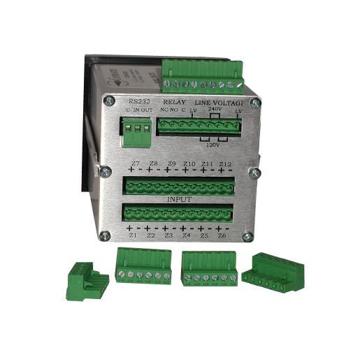
8 SECTION 4 PARTS OF THE INSTRUMENT 4.1 Front of the Scanner 4.3 Back of the Scanner AC Model During operation all open inputs should be shorted with wire Temperature\Setpoint Display- Main display with multiple functions. Temperature Scale Selection- Choice of C or F. Function Setting- Indicates the operating status of the instrument. Zone Setting- Indicates an active zone or a zone that is being set. Set\Shift\Reset Button- Used to recall the setpoint, to select digits during setup or to reset the alarm. Advance Digit Button- Used to increment selected digit. Load Button- Used to accept a setting. Line Voltage see P 11 RS-232 Port- Cable connection (see Section 1.3) C - Common Pin 5 IN - Input Pin 3 OUT - Output Pin 2 Relay NC- Non-energized Closed NO- Non-energized Open C- Common Line LV- 120VAC or 240VAC cable Jumpers- Determines voltage input (see Section 3.4) 14 15
9 4.3 Back of the Scanner DC Model 4.4 Temperature/Setpoint Display (Main Display) During "RUN" MODE, the Main Display is used to monitor zone temperatures, check Setpoints, and indicate ALARM conditions. During operator programming in "FUNCTION SELECT" MODE, the Main Display is used to: 1. Set the Zone Setpoints 2. Enter Passwords 3. Select Functions 4. Set the Zone Display Time 5. Select the Instrument Model During CALIBRATION (Function 9), the Main Display is used to: 1. Set calibration millivolts During operation all open inputs should be shorted with wire RS-232 Port- Cable connection (see Section 1.3) C - Common Pin 5 IN - Input Pin 3 OUT - Output Pin 2 Relay NC- Non-energized Closed NO- Non-energized Open C- Common Line LV- 9 to 36 VDC cable 16 17
10 SECTION 5 SETUP AND OPERATION There are two methods of setting up the CN600 Series scanner. The CN600 Series can be easily configured using the RS-232 Communications software or the scanner can be set up through it's front panel by using the following instructions. 5.1 "RUN" MODE Once the instrument is mounted and powered, it will go into "RUN" MODE. This is the basic operating mode for the CN606 in which each zone is sequentially scanned at approximately 4 complete scans per second (all zones) and each active zone is displayed for the scan time set by the operator (1 to 39 seconds). The last settings loaded will control the instrument. During "RUN" MODE, the operator is able to perform the following separate functions: 1. Check individual Setpoints by pressing & NOTE: In HI/LO Alarm Mode, the operator may toggle between HI and LO Setpoints by pressing 2. Lock individual Zones for monitoring by pressing Unlock with 3. Activate "FUNCTION SELECT" by pressing & NOTE: If the Password Function is enabled, the correct Password must be entered to access "FUNCTION SELECT" 5.2 Functions Functions are selected on the Main Display during "FUNCTION SELECT" MODE and transferred to the Function Display by the button. Ten Functions are available: Manual FUNCTION Section DISPLAYED DESCRIPTION "RUN" MODE (Monitor Zone Temperatures, Setpoints, Alarms) "FUNCTION SELECT" (Password Protection Option) Select Active Zones (Activate or Disable Zones) Set LO Setpoint Set HI Setpoint Serial Number (to set a one digit Instrument RS-232 address) Set Scan Time (1 to 39 seconds) Select Model (four digit model #: Alarm, Relay & F/C, Input, Type) Password Enable/Disable Calibration (with a Fixed Password) Functions Description RUN This is the basic operating mode entered on power-up. See SECTION 5.1 FUNCTION SELECT Enter This is the function from which most other Functions are available. See SECTION 5.4 To enable / disable password see Function 8 If password is enabled first digit in the top display will flash 0 to enter password see SECTION 5.6 [p 23] SELECT ACTIVE ZONES During "FUNCTION SELECT", use Main display. Press to load. The Main Display will become blank. A 2 will be shown in the Function Display. Zone "1" will be indicated in the Zone Display. to select 2 on the On the Zone display: Flashing "1"= Current Zone Disabled Steady "1" = Current Zone Active Push to change the status of the zone. When the correct zone status is set, push to advance to the next zone. Set the status of each zone and press to load all zones and return to FUNCTION SELECT MODE. SET LO SETPOINT During "FUNCTION SELECT", select 3 on the Main display. Load with A "3" will appear in the Function Display. The current zone will appear in the Zone Display. The Main Display will show the current setpoint with it's first digit flashing. If changes are required: Increment digit with Select digit with Load with and the next zone will appear. If no changes are required, push to check the next zone. When the setpoints for each zone have been checked or corrected, press & together to return to 19

11 FUNCTION SELECT MODE. SET HI SETPOINT Repeat procedure for "LO SETPOINT" but begin with selecting Function "4" and then set each zone's HI setpoint. SERIAL NUMBER One Digit Instrument Serial Number. Used for RS-232 addressing. Follow the same procedure as for Function 6 but select Function 5. SET SCAN TIME During "FUNCTION SELECT", select 6 on the Main display. Load with A 6 will appear in the Function Display. Two "Scan Time" digits will appear in the Temp. Display. Set the required scan time (within 1 and 40 seconds) using to increment and to select digit. Press to load and return to FUNCTION SELECT MODEL During "FUNCTION SELECT", select 7 on the Main Display. Load with Fourth Digit (Thermocouple) 0- Type B 1- Type C 2- Type E 3- Type J 4- Type K 5- Type R 6- Type S 7- Type T Press to load. The instrument will return to "FUNCTION SELECT" MODE. PASSWORD ENABLE/DISABLE Select 8 on the Main Display. Press to load. An "8" will appear in the Function Display. The first digit on the Main Display will flash "0" or "1", depending on the previous setting. To enable Password, enter "1" on the Main Display. To disable Password, enter "0" on the Main Display. Load and Exit with. CALIBRATION NOTE: To avoid any interference during calibration, disconnect the RS-232 wires from the scanner. THERMOCOUPLE UNIT WIRING: Parallel-connect all thermocouple terminals of the Input Connector as shown: A "7" will appear in the Function Display. A four-digit Model number will appear in the Main Display. Each digit represents an option available within the instrument. Choose a number for each digit that suits your needs. Increment with and select next digit with to choose the proper model from the list below: First Digit 0- Overheat Alarm (MSD) 1- Underheat Alarm 2- HI-LO Alarm Second Digit 0- Latching relay C 1- Latching relay F 2- Non Latching Relay C 3- Non Latching Relay F Third Digit (Factory Preset) 0- Thermocouple 1- RTD 20 Using copper wire, connect the positive and negative terminals of the Input connector to a presision millivoltmeter and a low output impedance source (10 ohm or less) set to 30mV ±2mV input. Set main display with buttons to enter four digit reading of the precision millivoltmeter. Then enter with button. When calibration is finished the unit will return to RUN mode. 21


12 RTD CALIBRATION RTD UNIT WIRING: Connect the upper Input Connector as shown on next page. In the lower Input Connector, connect a 330 Ohm ±5% resistor across each zone except Zone 3. Using copper wire, connect Zone 3 to a precision 300 Ohm±0.01% or 20 Ohm±0.01% resistor as shown: Allow the instrument to run for 15 minutes before calibrating. During 5.4 "FUNCTION SELECT" MODE "FUNCTION SELECT" is the mode through which most Functions are accessible. To access "FUNCTION SELECT" MODE, press & together while in "RUN" MODE. A "1" should appear in the Function Display. If it flashes, then the instrument is in "FUNCTION SELECT". If the "1" is steady, a Password is required. When in "FUNCTION SELECT" MODE, the fourth digit in the Main Display will flash "0". Use to increment this digit to the desired Function number (2-9) chosen from the Functions List. Press to load. "FUNCTION SELECT", select "9" on the Main Display. Press to load. The Function number selected will transfer to the Function Display and information relevant to that Function will appear in the Main and Zone Displays.. A "9" will appear in the Function Display and the Main Display will flash "0". A Fixed Password (0101) is now required to enter this Function to protect against accidental miscalibration. Follow the password entry procedure in Section 5.6. Platinum and Nickel Model Main display will flash 0300 Copper Model Main display will flash 0020 Press to load and activate SELF CHECK. For about 20 seconds, the display will flash the digits as shown: 5.5 Security The instrument is factory preset with a Four Digit Password (1011) to restrict access to settings. The Password can be enabled or disabled within Function 8 of the instrument. (If enabled, follow procedure 5.3) The Password can only be changed by computer using RS-232. There is also a fixed password to enter Function 9 Calibration. During this time, the scanner checks and callibrates itself. NOTE: Do not change the impedance source or resistor input during this SELF CHECK PERIOD. When SELF CHECK is finished, the display returns to "RUN" MODE and CALIBRATION IS COMPLETED 22 23


13 5.6 Entering the Password (Factory Preset) to access FUNCTION SELECT MODE NOTE: The Password can only be changed by a computer using RS-232 Communications. During "RUN" MODE, press and together to access "FUNCTION SELECT" MODE. If the Password security is enabled, a steady "1" will appear in the Function Display and the first digit in the Main Display will flash "0". If the Password security is disabled, a "1" will flash in the Function Display and the last digit in the Main Display will flash "0". TO ENTER PASSWORD Press again to shift to the third digit. 4. Press to increment the third digit to "1". 1. Press to increment the first digit to "1". 5. (Not illustrated) Shift to the fourth digit with increment the display to "1" with. and 6. Push to load the password. 2. Press to shift to the second digit. In this case, the second digit of the password is a "0"; there's no need to increment it
14 5.7 Wiring RTD Models NOTE: See Section 4.3 for thermocouple wiring.. Six Zone RTD- 2 Wire Six Zone RTD- 3 Wire Twelve Zone RTD- 2 Wire only 5.9 Thermocouple Ranges Standard Ranges 5.8 Wiring OC Models Output POWER SUPPLY (28VDC) COMMON During operation all open inputs should be shorted. RTD Pl & Ni shorted with 100 Ohm resistor RTD Copper shorted with 10 Ohm resistor 26 TC ºC Range ºF Range J K E T S R B N C Extended Ranges K E RTD Ranges 100 Ohm Platinum Ohm Nickel Ohm Nickel Ohm Copper
 Alarms Selectable")
15 SECTION 6 SPECIFICATIONS (Specification common to all Models) No. of Zones Six standard / Twelve Expanded Zone Display Time Adjust seconds Scan Time Approx. 1/4 sec Accuracy ±0.2% of Range ±2 C Resolution ±5uV Linearity ±1 C Scale Selectable C or F Open Input Flashing Display Alarm Relay 5 Amp; 120VAC Relay deenergizes on alarm Communication RS232 (3wire) Alarms Selectable HI, LO or HI/LO Alarm Range Full Range Terminals Headers for Plug-in Wiring Enclosure 1/4 Din Aluminum, 6" long Reset Manual Max. Voltage between Inputs 6VDC or RMS Reaction to Power Loss Unit returns to "RUN" MODE Main Display Four Digit; 0.6" high Ttermocouple Models Input Range Thermocouple Type Cold Junction Compensation RTD Models RTD (2 or 3 wire) 0-40mV Standard/ 0-75mV Expanded J,K,E,T,S,R,B,N,C Automatic 100 Ohm Pl 90 Ohm Ni 120 Ohm Ni 10 Ohm Cu Optional 6 Alarm Outputs (One for each Zone).5Amp@40VDC Open Collector Transistors External DC power required deenergize on alarm AC M0dels Line Power Power Consumption DC M0dels Line Power 120/240VAC; 50/60Hz 10VA Max. 9 to 36 VDC 28 WARRANTY / DISCLAIMER CONTRONAUTICS, INC. warrants this unit to be free of defects in materials and workmanship for a period of 13 months from date of purchase. CONTRONAUTICS Warranty adds an additional one (1) month grace period to the normal one (1) year product warranty to cover handling and shipping time. This ensures that Contronautic s customers receive maximum coverage on each product. If the unit malfunctions, it must be returned to the factory for evaluation. CONTRONAUTICS Customer Service Department will issue an Authorized Return (AR) number immediately upon phone or written request. Upon examination by CONTRONAUTICS, if the unit is found to be defective, it will be repaired or eplaced at no charge. CONTRONAUTICS WARRANTY does not apply to defects resulting from any action of the purchaser, including but not limited to mishandling, improper interfacing, operation outside of design limits, improper repair, or unauthorized modification. This WARRANTY is VOID if the unit shows evidence of having been tampered with or shows evidence of having been damaged as a result of excessive corrosion; or current, heat, moisture or vibration; improper specification; misapplication; misuse or other operating conditions outside of CONTRONAUTICS control. Components which wear are not warranted, including but not limited to contact points, fuses, and triacs. CONTRONAUTICS is pleased to offer suggestions on the use of its various products. However, CONTRONAUTICS neither assumes responsibility for any for omissions or errors nor assumes liability for any damages that result from the use of its products in accordance with information provided by CONTRONAUTICS, either verbal or written. CONTRONAUTICS warrants only that the parts manufactured by it will be as specified and free of defects. CONTRONAUTICS MAKES NO OTHER WARRANTIES OR REPRESENTATIONS OF ANY KIND WHATSOEVER, EXPRESS OR IMPLIED, EXCEPT THAT OF TITLE, AND ALL IMPLIED WARRANTIES INCLUDING ANY WARRANTY OF MERCHANTABILITY AND FITNESS FOR A PARTICULAR PURPOSE ARE HEREBY DISCLAIMED. LIMITATION OF LIABILITY: The remedies of purchaser set forth herein are exclusive, and the total liability of CONTRONAUTICS with respect to this order, whether based on contract, warranty, negligence, indemnification, strict liability or otherwise, shall not exceed the purchase price of the component upon which liability is based. In no event shall CONTRONAUTICS be liable for consequential, incidental or special damages. CONDITIONS: Equipment sold by CONTRONAUTICS is not intended to be used, nor shall it be used: (1) as a Basic Component under 10 CFR 21 (NRC), used in or with any nuclear installation or activity; or (2) in medical applications or used on humans. Should any Product(s) be used in or with any nuclear installation or activity, medical application, used on humans, or misused in any way, CONTRONAUTICS assumes no responsibility as set forth in our basic WARRANTY/DISCLAIMER language, and, additionally, purchaser will indemnify CONTRONAUTICS and hold CONTRONAUTICS harmless from any liability or damage whatsoever arising out of the use of the Product(s) in such a manner. RETURN REQUESTS/INQUIRIESDirect all arrant and repair requests/inquires to the CONTRONAUTICS Customer Service Department. BEFORE RETURNING ANY PRODUCT(S) TO CONTRONAUTICS, PURCHASER MUST OBTAIN AN AUTHORIZED RETURN (AR) NUMBER FROM CONTRONAUTICS CUSTOMER SERVICE DEPARTMENT (IN ORDER TO AVOID PROCESSING DELAYS), The assigned AR number should then be marked on the outside of the return package and on any correspondence.the purchaser is responsible for shipping charges, freight, insurance and proper packaging to prevent breakage in transit. CONTRONAUTICS policy is to make running changes, not model changes, whenever an improvement is possible. This affords our customers the latest in technology and engineering. CONTRONAUTICS is a registered trademark of CONTRONAUTICS, INCORPORATED. Copyright 1999 CONTRONAUTICS INCORPORTED All rights reserved. This document may not be copied, photocopied, reproduced, translated, or reduced to any electronic medium or machine-readable form, in whole or in part, without the prior written consent of CONTRONAUTICS, INC.

16
Table of Contents SECTION PAGE SECTION 1 INTRODUCTION Description Features Models... SECTION 2 RS-232 COMMUNICATIONS...
 SECTION Table of Contents SECTION 1 INTRODUCTION...................... 1.1 Description............................... 1.2 Features................................. 1.3 Models..................................
Table of Contents SECTION PAGE
 Table of Contents SECTION PAGE SECTION 1 INTRODUCTION................... 1.1 Description.............................. 1.2 Features................................ 1.3 Models.................................
User s Guide. CN616 Series 1 4 DIN Economical 6-Zone PID Temperature Controllers. Shop online at omega.com SM
 User s Guide Shop online at omega.com SM e-mail: info@omega.com For latest product manuals: www.omegamanual.info CN616 Series 1 4 DIN Economical 6-Zone PID Temperature Controllers omega.com info@omega.com
OM-CP-Cryo-Temp Ultra Low Temperature Data Logger. Shop online at. omega.com For latest product manuals: omegamanual.
 MADE IN Shop online at omega.com e-mail: info@omega.com For latest product manuals: omegamanual.info OM-CP-Cryo-Temp Ultra Low Temperature Data Logger OM-CP-Cryo-Temp Product Notes Manual Start When the
User s Guide HHAQ-109. Portable Multi-gas Detector. Shop online at omega.com SM
 User s Guide Shop online at omega.com SM e-mail: info@omega.com For latest product manuals: www.omegamanual.info HHAQ-109 Portable Multi-gas Detector User Guide Thanks for our using our products. Before
LVCN-302 Set-Up Manual for Sump Model
 omega.com LVCN302 SetUp Manual for Sump Model User s Guide MADE IN Specifications: : Isolated input accepts any type of 420 ma process signal. Loop power available up to 24VDC for 2 wire device Input Power:
User s Guide. Shop online at. Made in China. Two-wire Display and Control Unit
 Made in China User s Guide Two-wire Display and Control Unit Shop online at omega.com e-mail: info@omega.com For latest product manuals: omegamanual.info Manual for 2-wire LCD display and control unit
User s Guide. FLSW Series ROTAMETER WITH ALARM. Shop online at omega.com. For latest product manuals:
 TM User s Guide Shop online at omega.com e-mail: info@omega.com For latest product manuals: www.omegamanual.info FLSW Series ROTAMETER WITH ALARM omega.com info@omega.com U.S.A. Headquarters: Servicing
User s Guide. Setpoint Option Card. Shop online at. omega.com For latest product manuals: omegamanual.
 User s Guide Shop online at omega.com e-mail: info@omega.com For latest product manuals: omegamanual.info LDP6-CDS Setpoint Option Card LP0683X OMEGAnet Online Service omega.com Internet e-mail info@omega.com
ModSync Sequencing System Installation & Operation Manual. For use with Fulton Steam Boilers.
 ModSync Sequencing System Installation & Operation Manual For use with Fulton Steam Boilers. Revision 3.0 8/21/2008 - 2 - Table of Contents Introduction Page 4 Features Page 4 Sequence of Operation Page
Series: MBC1-TC Mini Benchtop Temperature Controller
 User s Guide Series: MBC1-TC Mini Benchtop Temperature Controller Imagine Instruments LLC:: 4500 Williams Drive, Ste 212-318 :: Georgetown, TX 78633 :: p. 855.574.6243 e-mail: info@imagineinstruments.com
Mark 25 Ultrapure Water Conductivity Analyzer
 Martek Instruments, Inc. Mark 25 Ultrapure Water Conductivity Analyzer Instruction Manual WARRANTY POLICY Unless otherwise stated, MARTEK INSTRUMENTS, INC. warrants this equipment to be free from defects
Duct Humidity/Temp Sensor
 Duct Humidity/Temp Sensor Model HU-226 RoHS Ultra fast response cross-linked bulk polymer capacitive sensing element Proprietary hydrophobic and oleophobic eptfe filter to protect the sensing element from
User Manual. Humidity-Temperature Chart Recorder. Model RH520
 User Manual Humidity-Temperature Chart Recorder Model RH520 Introduction Congratulations on your purchase of the Extech RH520 Temperature + Humidity Chart Recorder. The RH520 measures and displays Temperature,
CONsOlIDATOR 4 & 8. MulTI- C h ANNEl CONTROllERs. ConsoliDator 4 Model PD940 ConsoliDator 4 Features. ConsoliDator 8 Features.
 CONsOlIDATOR 4 & 8 MulTI- C h ANNEl CONTROllERs ConsoliDator 4 Model PD940 ConsoliDator 4 Features Four 4-20 Four 4-20 Outputs ConsoliDator 8 Features Eight 4-20 Two 4-20 Outputs Common Features Four Pulse
Series Temperature Controller Instruction Sheet
 Series Temperature Controller Instruction Sheet Thank you very much for purchasing DELTA A Series. Please read this instruction sheet before using your A series to ensure proper operation and please keep
User s Guide TOTE SERIES. Wrap-Around Tote Tank Headers. TOTE SERIES Wrap-Around Tote Tank Heaters. Shop online at omega.com
 TM TABLE OF CONTENTS User s Guide Introduction... 2 Applications... 2 Approvals... 2 Important Safety Instructions... 3 General Specifications... 4 Installation / Operating Instructions... 5 Emergency
SEC 2000 Millenium Infrared Gas Detector
 SEC 2000 Millenium Infrared Gas Detector Instruction and Operation Manual Sensor Electronics Corporation 5500 Lincoln Drive Minneapolis, Minnesota 55436 USA (952) 938-9486 Fax (952) 938-9617 Email: sales@sensorelectronic.com
User s Guide. OSXL685 and OSXL689. High Performance Infrared Thermometer. Shop online at
 User s Guide Shop online at omega.com e-mail: info@omega.com For latest product manuals: omegamanual.info TM WITH BUILT-IN PATENTED LASER CIRCLE SIGHTING OSXL685 and OSXL689 High Performance Infrared Thermometer
Outside Air Humidity & Temperature Sensor
 Outside Air Humidity & Temperature Sensor RoHS Model HU-227 Ultra fast response cross-linked bulk polymer capacitive sensing element Proprietary hydrophobic and oleophobic eptfe filter to protect the sensing
Isolated Thermocouple Module
 User Manual for the HE693THM665, HE693THM666, HE693THM667, HE693THM668 Isolated Thermocouple Module Twelfth Edition 19 April 2004 PREFACE 19 APR 2004 PAGE 3 PREFACE This manual explains how to use the
Process & TeMPerATUre UniversAl input DigiTAl MeTers
 Process & TeMPerATUre UniversAl input DigiTAl MeTers nova PD56 series Thermocouple, rtd, & Process inputs Universal Power supply 1-24 va c Up to 3 Alarm relays retransmitting 4-2 ma output input Max/Min
Series Digital Controller Instruction Sheet
 216/3/11 Series Digital Controller Instruction Sheet Thank you very much for purchasing DELTA DTC Series Temperature Controller. Please read this instruction sheet before using your DTC series to ensure
Humidity Monitor model 01080
 Instruction Manual Humidity Monitor model 01080 Features & Benefits 19 18 1 2 3 4 12 11 10 17 16 5 9 RECORDS ºC/ºF 15 14 FRONT 6 7 8 1. Humidity Level Indicator Indicates a high, low or ideal humidity
PROCESS & TEMPERATURE UNIVERSAL INPUT DIGITAL METERS
 PROCESS & TEMPERATURE UNIVERSAL INPUT DIGITAL METERS NOVA PD56 Series Thermocouple, RTD, & Process Inputs Universal Power Supply 1-24 VAC Up to 3 Alarm Relays Retransmitting 4-2 ma Output Input Max/Min
Nov 08 PRODUCT SPECIFICATION SHEET
 Honeywell UDC1200 and UDC1700 MICRO-PRO SERIES UNIVERSAL DIGITAL CONTROLLERS 51-52-03-35 Nov 08 PRODUCT SPECIFICATION SHEET OVERVIEW The UDC1200 & UDC1700 are microprocessor-based 1/16 DIN and 1/8 DIN
Thermometer model 02059
 Instruction Manual Thermometer model 02059 pm CONTENTS Unpacking Instructions... 2 Package Contents... 2 Product Registration... 2 Features & Benefits: Sensor... 2 Features & Benefits: Display... 3 Setup...
Remote Relay Module (RRM)
") Remote Relay Module (RRM) Instruction Manual WARNING THIS MANUAL MUST BE CAREFULLY READ BY ALL INDIVIDUALS WHO HAVE OR WILL HAVE THE RESPONSIBILITY FOR INSTALLING, USING OR SERVICING THIS PRODUCT. Like
Remote Relay Module (RRM) Instruction Manual WARNING THIS MANUAL MUST BE CAREFULLY READ BY ALL INDIVIDUALS WHO HAVE OR WILL HAVE THE RESPONSIBILITY FOR INSTALLING, USING OR SERVICING THIS PRODUCT. Like
User s Guide CN616A. Universal 6 Channel ¼ DIN Process Controller. Shop online at omega.com
 TM User s Guide Shop online at omega.com e-mail: info@omega.com For latest product manuals: www.omegamanual.info CN616A Universal 6 Channel ¼ DIN Process Controller omega.com info@omega.com U.S.A. Headquarters:
UDC1000 and UDC1500 MICRO-PRO SERIES UNIVERSAL DIGITAL CONTROLLERS
 UDC1000 and UDC1500 MICRO-PRO SERIES UNIVERSAL DIGITAL CONTROLLERS EN0I-6041 4/01 PRODUCT SPECIFICATION SHEET OVERVIEW The UDC1000 and UDC1500 are microprocessor-based 1/16 DIN and 1/8 DIN controllers
Duct Temperature Sensors
 Duct s Model TE-701 / 702 RoHS More than 16 types of interchangeable NTC thermistors, precision platinum, nickel or balco RTDs are available for universal compatibility. Five installation options probe
Oakton TEMP 9500 Advanced Multiparameter Controller
 Oakton TEMP 9500 Advanced Multiparameter Controller Models: 89800-03 & 89800-04 Oakton Instruments 625 E Bunker Ct. Vernon Hills, IL 60061, USA 1-888-4OAKTON (1-888-462-5866) info@4oakton.com Contents
TMC. Installation and Operation Manual TMC. Temperature and Pressure Monitoring for Heating and Cooling Applications. Temperature Monitoring Control
 Installation and Operation Manual Temperature and Pressure Monitoring for Heating and Cooling Applications Temperature Monitoring Control VALVE OPEN ALARM System= 128 o F Alarm At= 130 o F RESET /BACK
MODEL 8143 SIGNAL SELECTOR INSTALLATION AND OPERATION MANUAL
 MODEL 8143 SIGNAL SELECTOR INSTALLATION AND OPERATION MANUAL 95 Methodist Hill Drive Rochester, NY 14623 Phone: US +1.585.321.5800 Fax: US +1.585.321.5219 www.spectracomcorp.com Part Number 8143-5000-0050
DIGITAL METERS Large Display Temperature Meters Instruction Manual
 DIGITAL METERS Large Display Temperature Meters PD755 PD756 PD757 Handles Thermocouple & RTD Inputs with Simplicity J, K, T, E, R, & S Thermocouples 100 Ω Platinum RTD (0.00385 or 0.00392 curve) Large
Room Humidity/Temp Sensor
 Room Humidity/Temp Sensor Model HU-225-EU (Not Available in North America) RoHS Ultra fast response cross-linked bulk polymer...capacitive sensing element Proprietary hydrophobic and oleophobic eptfe filter
Figure 1. Proper Method of Holding the ToolStick. Figure 2. Improper Method of Holding the ToolStick
 CAN OBD READER REFERENCE DESIGN KIT USER GUIDE 1. Standard ToolStick Handling Recommendations The ToolStick Base Adapter and daughter cards are distributed without any protective plastics. To prevent damage
INSTRUCTION MANUAL P Heating and 1 Cooling
 REPLACEMENT COMPONENTS DIVISION CARRIER CORPORATION www.totaltouch.info Technical Support: 1-866-90TOUCH (1-866-908-6824) INSTRUCTION MANUAL P286-1200 2 Heating and 1 Cooling Physical Dimensions Case:
Advanced Test Equipment Rentals ATEC (2832)
") Established 1981 Advanced Test Equipment Rentals www.atecorp.com 800-404-ATEC (2832) FEATURES AND SPECIFICATIONS MOLYTEK 2702 AND 3702 RECORDERS 2702 3702 REV: 03302004 Standard Specifications for Model
Established 1981 Advanced Test Equipment Rentals www.atecorp.com 800-404-ATEC (2832) FEATURES AND SPECIFICATIONS MOLYTEK 2702 AND 3702 RECORDERS 2702 3702 REV: 03302004 Standard Specifications for Model
MODEL QTS-1800 SERIES WALL MOUNT DIGITAL AND ANALOG TRANSMITTER/SENSOR
 MODEL QTS-1800 SERIES WALL MOUNT DIGITAL AND ANALOG TRANSMITTER/SENSOR INSTALLATION OPERATION AND MAINTENANCE MANUAL QUATROSENSE ENVIRONMENTAL LTD. 5935 OTTAWA STREET, PO BOX 749 RICHMOND, ONTARIO CANADA
TL-105 COLUMN HEATER
 TL-105 COLUMN HEATER INSTRUCTION MANUAL Timberline Instruments Inc. 1880 S. Flatiron Ct., Unit I Boulder, Colorado 80301 Ph: (303) 440-8779 Fx: (303) 440-8786 info@timberlineinstruments.com www.timberlineinstruments.com
The EGT-1 is a single channel fully programmable digital EGT (Exhaust Gas Temperature) gauge.
 gauge.") EGT-1 EGT (Exhaust Gas Temperature) Gauge Operating Manual English 1.02 Introduction The EGT-1 is a single channel fully programmable digital EGT (Exhaust Gas Temperature) gauge. The EGT-1 s high accuracy
EGT-1 EGT (Exhaust Gas Temperature) Gauge Operating Manual English 1.02 Introduction The EGT-1 is a single channel fully programmable digital EGT (Exhaust Gas Temperature) gauge. The EGT-1 s high accuracy
Beacon 800 Gas Monitor Operator s Manual
 Beacon 800 Gas Monitor Operator s Manual Part Number: 71-0037RK Revision: F Released: 4/18/17 www.rkiinstruments.com Product Warranty RKI Instruments, Inc. warrants gas alarm equipment sold by us to be
Room Monitor SAVE THIS MANUAL FOR FUTURE REFERENCE.
 Instruction Manual Room Monitor model 00276RM CONTENTS Unpacking Instructions... 2 Package Contents... 2 Product Registration... 2 Features & Benefits... 3 Setup... 4 Placement Guidelines... 5 Using the
Inline Heater for Solvent or Gas. Installation and Operation Manual
 SH Series Inline Heater for Solvent or Gas Installation and Operation Manual This instruction manual explains the basic operation of the Process Technology inline solvent or gas heater. We recommend reading
Sentry LIQUID LEVEL CONTROLLER MODEL 120 OPERATING MANUAL.
 Sentry LIQUID LEVEL CONTROLLER MODEL 120 OPERATING MANUAL www.aquaticsentry.com TABLE OF CONTENTS 1. SAFETY PRECAUTIONS... 3 2. APPLICATION... 3 2.1 HIGH AND LOW LEVEL ALARM 2.2 PUMP DOWN CONTROLLER 2.3
GG-EM ENTRANCE MONITOR. Installation and Operation Manual
 GG-EM ENTRANCE MONITOR Installation and Operation Manual 2 GG-EM Warning Use this product only in the manner described in this manual. If the equipment is used in a manner not specified by Calibration
RS485 MODBUS Module 8AI
 Version 1.4 15/04/2013 Manufactured for Thank you for choosing our product. This manual will help you with proper support and proper operation of the device. The information contained in this manual have
Installation and Operations Manual
 Installation and Operations Manual H-IM-LLC February 2018 Part No. 25092501 Replaces H-IM-LLC (01/2014) Lead Lag Control System Table of Contents General Safety Information 2 Inspection 2 Warranty Statement
108A OTP1800. Grid Support. General Description
 Operation Manual 108A OTP1800 ON/OFF Main Switch On/Off Alarm Switch Digital Control Module Grid Support Alarm Fuse 250 Volt 15 amp Load Outlet Sensor Input Inlet General Description This control is a
eed quality electronic design USER s MANUAL
 eed quality electronic design www.dem-it.com eed www.qeed.it info@qeed.it ANALOG SIGNAL DISPLAY Q-DISP-T USER s MANUAL The displays Q-DISP-T, prepared for mounting on the back panel, 96x48mm, will allow
DESCRIPTIVE AND INSTALLATION INSTRUCTION MANUAL FOR MODEL AH1000, BH1000, AND EH1000 SERIES ANNUNCIATORS
 DESCRIPTIVE AND INSTALLATION INSTRUCTION MANUAL FOR MODEL AH1000, BH1000, AND EH1000 SERIES ANNUNCIATORS SEEKIRK, INC. 2420 Scioto Harper Dr. Columbus, OH 43204 Tel: (614) 278-9200 FAX: (614) 278-9257
OVEN INDUSTRIES, INC.
 OVEN INDUSTRIES, INC. OPERATING MANUAL Model 5C7-252 TEMPERATURE CONTROLLER With PLC Inputs Introduction Thank you for purchasing our controller. The Model 5C7-252 is an exceptionally versatile unit and
Sierra Series 900 Single & Dual Channel System. Instruction Manual
 Series 240/24 Instruction Manual Table of Contents Sierra Series 900 Single & Dual Channel System Instruction Manual Part Number IM-90-07/05 Revision D. 5 Harris Court, Building L Monterey, CA 93940 (83)
TCA-9102 Series Surface Mount Temperature Controllers with High and Low Alarm
 TCA-9102 Series Surface Mount Temperature Controllers with High and Low Alarm General Description & Applications The TCA-9102 Series Temperature Controller with Alarm offers a versatile solution for a
Model 4001 Series Single Channel Controller
 Model 4001 Series Single Channel Controller Sierra Monitor Corporation 1991 Tarob Court, Milpitas, CA 95035 (408) 262-6611 (800) 727-4377 (408) 262-9042 - Fax E-Mail: sales@sierramonitor.com Web site:
Blade Series Heat Exchanger Operation and Installation
 Blade Series Heat Exchanger Operation and Installation *IMPORTANT* For safe and satisfactory operation, please read the following instructions. Keep these instructions for future reference. Some information
DESCRIPTIVE AND INSTALLATION INSTRUCTION MANUAL FOR MODEL G1000 AND H1000 SERIES ANNUNCIATORS
 DESCRIPTIVE AND INSTALLATION INSTRUCTION MANUAL FOR MODEL G1000 AND H1000 SERIES ANNUNCIATORS SEEKIRK, INC. 2420 Scioto Harper Dr. Columbus, OH 43204 Tel: (614) 278-9200 FAX: (614) 278-9257 email: seekirk@seekirk.com
User s Guide. LVU-800, & LV U Ultrasonic Level System
 M-2051 1/22/02 1:03 PM Page 2 W h e re Do I Find Everything I Need for P rocess Measurement and Control? OMEGA Of Course! Shop online at www.omega.com T E M P E R AT U R E Thermocouple, RTD & Thermistor
Instruction Manual WARNING
 Controllers Instruction Manual WARNING THIS MANAUL MUST BE CAREFULLY READ BY ALL INDIVIDUALS WHO HAVE OR WILL HAVE THE RESPONSIBILITY FOR INSTALLING, USING OR SERVICING THIS PRODUCT. Like any piece of
OMB-DAQ-TC-RACK-EXP32
 User s Guide Shop online at omega.com SM e-mail: info@omega.com For latest product manuals: www.omegamanual.info OMB-DAQ-TC-RACK-EXP32 32-Channel Expansion Module for OMB-DAQ-TC-RACK USB/Ethernet Based
Document No
 CO Guardian LLC 1951 E. Airport Dr. Tucson, AZ 85706 CARBON MONOXIDE DETECTOR MODEL 452 INSTALLATION AND OPERATIONAL MANUAL Document No. 01-2510-02 MODEL 452 INSTALLATION AND OPERATIONAL MANUAL Page 1
INSTRUCTIONS FOR THE LCR10 TEN INCH CIRCULAR CHART RECORDER
 INSTRUCTIONS FOR THE LCR10 TEN INCH CIRCULAR CHART RECORDER LOVE LOVE CONTROLS a Division of Dwyer Instruments, Incorporated PO Box 338 Michigan City, IN 46361-0338 (800) 828-4588 (219) 879-8000 FAX (219)
NOVUS AUTOMATION 1/5. Range: -35 to 720 C (-31 to 1328 F) Range: -90 to 1300 C (-130 to 2372 F) Range: 0 to 1760 C (-32 to 3200 F)
 Range: -90 to 1300 C (-130 to 2372 F) Range: 0 to 1760 C (-32 to 3200 F)") E N R S B Pt100 Pt100 Range: -35 to 720 C (-31 to 1328 F) Range: -90 to 1300 C (-130 to 2372 F) Range: 0 to 1760 C (-32 to 3200 F) Range: 0 to 1760 C (-32 to 3200 F) Range: 150 to 1820 C (302 to 3308 F)
E N R S B Pt100 Pt100 Range: -35 to 720 C (-31 to 1328 F) Range: -90 to 1300 C (-130 to 2372 F) Range: 0 to 1760 C (-32 to 3200 F) Range: 0 to 1760 C (-32 to 3200 F) Range: 150 to 1820 C (302 to 3308 F)
GasScanner 8C. Eight Channel Monitor. Operator s Manual. MINT-0281-XX Rev. A 01/29/08
 GasScanner 8C Eight Channel Monitor Operator s Manual MINT-0281-XX Rev. A 01/29/08 Product Warranty Matheson Tri-Gas, Inc., warrants gas alarm equipment sold by us to be free from defects in materials,
Controllers. Instruction Manual WARNING
 Controllers Instruction Manual WARNING THIS MANUAL MUST BE CAREFULLY READ BY ALL INDIVIDUALS WHO HAVE OR WILL HAVE THE RESPONSIBILITY FOR INSTALLING, USING OR SERVICING THIS PRODUCT. Like any piece of
SAFETY INFORMATION AND WARNINGS
 This manual refers to the Model SST-3 control panel manufactured since October 31, 2013, which uses a universal (100 277 VAC; 50/60 Hz) power supply. Older units use a voltage-specific power supply and
Duct Mount. Installation Instructions
 Duct Mount Installation Instructions 00809-0600-4975 Legal Notice The Flame Detector described in this document is the property of Rosemount. No part of the hardware, software, or documentation may be
CO Guardian LLC Document: E. AIRPORT DRIVE Date: 11/15/05 OWNERS MANUAL
 OWNERS MANUAL CARBON MONOXIDE DETECTOR MODELS Panel mount and Remote Detectors (R) (353 and 353R) 353 FAMILY MODEL OWNERS/INSTALLATION MANUAL Page 1 of 22 LOG OF REVISIONS REV NO. PAGE NO. DATE DESCRIPTION
Pioneer-R16 Gas Monitor Operator s Manual
 Pioneer-R16 Gas Monitor Operator s Manual Edition 7/2/97 RKI INSTRUMENTS, INC RKI Instruments, Inc. 33248 Central Ave, Union City, CA 94587 (510) 441-5656 Chapter 1: Description About the Pioneer-R16 Gas
Ion Genesis II Pump Controller Digital Level Control with Pump Alternation and High Water Alarm
 Page 1 of 8 General Overview Thank you for purchasing an Ion Genesis controller. Take the time to read the instructions carefully before using this appliance. We strongly recommend that you keep this instruction
Model Gas Alarm Panel APPLICABILITY & EFFECTIVITY. This manual provides instructions for the following Sierra Monitor products:
 Model 2102 Gas Alarm Panel APPLICABILITY & EFFECTIVITY This manual provides instructions for the following Sierra Monitor products: Model Description 2102-00 Alarm Panel 2 Channel 2102-01 Alarm Panel 2
QAS SERIES PLUG-IN CONTROLLERS c/w SOLID STATE SENSOR
 QAS-10000 SERIES PLUG-IN CONTROLLERS c/w SOLID STATE SENSOR INSTALLATION, OPERATION AND MAINTENANCE MANUAL QUATROSENSE ENVIRONMENTAL LTD. 5935 OTTAWA STREET, PO BOX 749, RICHMOND, ONTARIO, CANADA. K0A
VX SERIES Wireless Thermostat with Occupancy Sensor
 VX SERIES Wireless Thermostat with Occupancy Sensor INSTRUCTION MANUAL Table of Contents Thermostat Installation... 7 Installing the Wireless Control Card...8 Mounting the thermostat to the wall...9 Thermostat
6502B RF Distribution
 6502B RF Distribution User Guide Revision A - March 2004 Part Number 15247-201 Table of Contents Table of Contents About this User Guide Purpose...................................................... 1
JIR-301-M No.JIR31E To prevent accidents arising from the misuse of this instrument, please ensure the operator receives this manual.
 INSTRUCTION MANUAL MICRO-COMPUTER BASED DIGITAL INDICATOR JIR-31-M No.JIR31E3 24.7 To prevent accidents arising from the misuse of this instrument, please ensure the operator receives this manual. SAFETY
Carbon Monoxide Transmitter
 Introduction The CO Transmitter uses an electrochemical sensor to monitor the carbon monoxide level and outputs a field-selectable 4-20 ma or voltage signal. The voltage signal may also be set to 0-5 or
UDC 700 Universal Digital Controllers and Indicator Specifications
 UDC 700 Universal Digital Controllers and Indicator Specifications 51-52-03-28 August 2002 Overview The UDC 700 is a 1/32 DIN (49 x 25 mm) controller which combines a high degree of technology and quality
Instruction Manual US PAT: 6,824,069 6,786,421. Models: CT03TS21 CTO3TS32 CTO3TS32H
 Instruction Manual US PAT: 6,824,069 6,786,421 Models: CT03TS21 CTO3TS32 CTO3TS32H www.climatouch.com AED Electronics Inc. 5758 Royalmount Avenue Montreal, Quebec,Canada H4P 1K5 Technical Support: 1-866-90TOUCH
AutomationDirect PM24. Microprocessor - Based Process/Temperature Limit Controller. Operator s Manual. Technical Support.
 AutomationDirect 1/16 DIN Series Technical Support We strive to make our manuals the best in the industry. We rely on your feedback to let us know if we are reaching our goal. If you cannot find the solution
Tempco Part Number PCT30006 Temperature Control Enclosure with Relay Output for Tote Tank Heating Applications
 Instruction Manual Tempco Part Number PCT30006 Temperature Control Enclosure with Relay Output for Tote Tank Heating Applications Manual PCT30006, Revision 9/20/2016 The PCT30006 control enclosure incorporates
F PC and AO OUTPUT BOARDS INSTRUCTION MANUAL. Blue-White. Industries, Ltd.
 F-2000 PC and AO OUTPUT BOARDS INSTRUCTION MANUAL Blue-White R Industries, Ltd. 500 Business Drive Huntington Beach, CA 92649 USA Phone: 714-89-8529 FAX: 714-894-9492 E mail: sales@blue-white.com or techsupport@blue-white.com
INSTRUCTION MANUAL TS21. 2 Heating and 1 Cooling
 INSTRUCTION MANUAL TS21 2 Heating and 1 Cooling WELCOME TO Flexible applications - Universal and easy to install in residential or commercial environments. Advanced features - Precision electronics provide
tcm100, tcm101 Series Temperature Control Modules and PTS100, PTS100/3 Pipe Temperature Sensors Operations Manual
 tcm100, tcm101 Series Temperature Control Modules and PTS100, PTS100/3 Pipe Temperature Sensors Operations Manual This manual covers operation of the tcm100 and tcm101 Series Temperature Control Modules.
User s Guide DP606A/DP612A. Shop online at omega.com. Universal 6/12 Channel ¼ DIN Panel Meter
 TM User s Guide Shop online at omega.com e-mail: info@omega.com For latest product manuals: www.omegamanual.info DP606A/DP612A Universal 6/12 Channel ¼ DIN Panel Meter omega.com info@omega.com U.S.A. Headquarters:
Thermometer with Probe model 00891A
 Instruction Manual Thermometer with Probe model 00891A CONTENTS Unpacking Instructions... 2 Package Contents... 2 Product Registration... 2 Features & Benefits... 3 Setup... 4 Temperature Units... 4 Placement
JENCO ELECTRONICS, LTD.
 OPERATION MANUAL THE JENCO MODEL 3677 1/8 DIN ph/orp CONTROLLER JENCO ELECTRONICS, LTD. MANUFACTURER OF PRECISON INSTRUMENTS GENERAL INTRODUCTION The model 3677 is a precise instrument for the measurement
Model 1062 Environment Monitor
 Model 1062 Environment Monitor Continuously Monitors Environment Temperature Humidity Barometric Pressure Line Voltage Line Frequency Applications Manufacturing The 1062A Environment Monitor will ensure
AUTOMATION. Operator s Manual RST Series Web Enabled Input Module. Rev. A2, 1/12
 AUTOMATION P R O D U C T S GROUP, INC. Operator s Manual RST-5000 Series Web Enabled Input Module Rev. A2, 1/12 Tel: 1/888/525-7300 Fax: 1/435/753-7490 www.apgsensors.com E-mail: sales@apgsensors.com RST-5000
F500 Elite. FIELDBUS ADAPTER. Watchdog NTC to Modbus RTU communications. (Software Version 3.3.0)
") F500 Elite. FIELDBUS ADAPTER. Watchdog NTC to Modbus RTU communications. (Software Version 3.3.0) Approvals: Suitable for use in Hazardous Locations CL II Div 1 GPS E, F & G (CANADA ONLY) CL II Div 2 GPS
F500 Elite. FIELDBUS ADAPTER. Watchdog NTC to Modbus RTU communications. (Software Version 3.3.0) Approvals: Suitable for use in Hazardous Locations CL II Div 1 GPS E, F & G (CANADA ONLY) CL II Div 2 GPS
User's Guide. Pinless Moisture Meter. Model MO257
 User's Guide Pinless Moisture Meter Model MO257 Introduction Congratulations on your purchase of the Extech MO257 Pinless Moisture Meter. The pinless moisture sensor monitors the moisture in wood and other
Tempco PCT-3000 Series Temperature Control Console with Relay Output for Heating or Cooling Applications
 Instruction Manual Tempco PCT-3000 Series Temperature Control Console with Relay Output for Heating or Cooling Applications Manual PCT-3000 Revision 9/2014 The PCT-3000 series control console incorporates
OWNERS MANUAL. CARBON MONOXIDE DETECTOR MODELS Panel Mount & Remote Detectors (R) Guardian Avionics 1951 E. AIRPORT DRIVE TUCSON, AZ.
 Guardian Avionics 1951 E. AIRPORT DRIVE TUCSON, AZ.") OWNERS MANUAL CARBON MONOXIDE DETECTOR MODELS Panel Mount & Remote Detectors (R) (353-101 and 353-201) 353 FAMILY MODEL OWNERS/INSTALLATION MANUAL Page 1 of 22 LOG OF REVISIONS REV NO. PAGE NO. DATE DESCRIPTION
OWNERS MANUAL CARBON MONOXIDE DETECTOR MODELS Panel Mount & Remote Detectors (R) (353-101 and 353-201) 353 FAMILY MODEL OWNERS/INSTALLATION MANUAL Page 1 of 22 LOG OF REVISIONS REV NO. PAGE NO. DATE DESCRIPTION
User s Guide OS210-C4. IR Temperature Sensors. Shop online at omega.com. For latest product manuals: omegamanual.
 User s Guide Shop online at omega.com e-mail: info@omega.com For latest product manuals: omegamanual.info MADE IN UNITED KINGDOM OS210-C4 IR Temperature Sensors OMEGAnet Online Service omega.com Internet
Installation Manual. THM-0100 Setpoint Thermostat Version THM HBX Control Systems Inc.
 Installation Manual M-000 Setpoint Thermostat Version.04 M-000 HBX Control Systems Inc. TABLE OF CONTENTS Introduction Index Safety symbols and Warnings Index Receipt and Inspection Description Technical
Temperature Controllers
 Model TEC-4100 1/4 DIN Model TEC-4100 1/4 DIN Temperature Controller Ordering Code: Power Input BOX 1 4 = 90-250 VAC 5 = 11-26 VAC / VDC TEC-4100- Configurable for 4 Programmable Outputs and NEMA 4X/IP65
Beacon 410A Gas Monitor Operator s Manual
 Beacon 410A Gas Monitor Operator s Manual Part Number: 71-0397 Revision: F Released: 12/5/17 www.rkiinstruments.com Product Warranty RKI Instruments, Inc., warrants gas alarm equipment sold by us to be
Warranty Registration
 WARRANT Y AND LIMITS OF LIABILIT Y Vulcain Inc. warrants to the original purchaser that its product and the component parts thereof will be free from defects in workmanship and materials for a period of
OPERATION & INSTALLATION MANUAL
 OPERATION & INSTALLATION MANUAL Model: SIO 14 & SIO 18 Electric Tankless Hot Water Generators Table of Contents SAFETY INFORMATION... 1 INTRODUCTION... 2 Unit Operation:... 2 Unit Freezing:... 3 Maintenance:...
Pipo Communications. Model ST-888. DTMF ANI/ENI Display Decoder
 Pipo Communications Model ST-888 DTMF ANI/ENI Display Decoder 1516 Cassil Place Hollywood, California 90028-7106 Phone: 323-466-5444 Fax: 323-466-1520 www.pipo.cc Manual # 68-9888 May 1, 2002 Rev. 5/02