F500 Elite. FIELDBUS ADAPTER. Watchdog NTC to Modbus RTU communications. (Software Version 3.3.0)
|
|
|
- Alaina Heath
- 5 years ago
- Views:
Transcription
1 F500 Elite. FIELDBUS ADAPTER. Watchdog NTC to Modbus RTU communications. (Software Version 3.3.0) Approvals: Suitable for use in Hazardous Locations CL II Div 1 GPS E, F & G (CANADA ONLY) CL II Div 2 GPS F & G (USA ONLY)
2 CONTENTS INTRODUCTION 1 SPECIFICATIONS 2 INSTALLATION INSTRUCTIONS 3 ELECTRICAL WIRING 4 OPERATING INSTRUCTIONS FAULT FINDING CONTACT INFORMATION DRAWINGS A B C D E CONNECTING THE F500 ELITE TO AN AC SUPPLY CONNECTING THE F500 ELITE TO A DC SUPPLY F500 ELITE TO WATCHDOG ELITE CONNECTIONS F500 ELITE TO VT100 SERIAL TERMINAL CONNECTIONS GENERAL CONNECTION DETAIL APPENDIX A SETTING THE MODULE SWITCHES 2
3 Dear 4B Customer: Congratulations on your purchase. 4B appreciates your business and is pleased you have chosen our products to meet your needs. Please read in its entirety and understand the literature accompanying the product before you place the product into service. Please read the safety precautions carefully before operating the product. With each product you purchase from 4B, there are some basic but important safety considerations you must follow to be sure your purchase is permitted to perform its design function and operate properly and safely, giving you many years of reliable service. Please read and understand the Customer Safety Responsibilities listed below. Failure to follow this safety directive and the Operation Manuals and other material furnished or referenced, may result in serious injury or death. SAFETY NOTICE TO OUR CUSTOMERS A. In order to maximize efficiency and safety, selecting the right equipment for each operation is vital. The proper installation of the equipment, and regular maintenance and inspection is equally important in continuing the proper operation and safety of the product. The proper installation and maintenance of all our products is the responsibility of the user unless you have asked 4B to perform these tasks. B. All installation and wiring must be in accordance with Local and National Electrical Codes and other standards applicable to your industry. (Please see the article Hazard Monitoring Equipment Selection, Installation and Maintenance at The installation of the wiring should be undertaken by an experienced and qualified professional electrician. Failure to correctly wire any product and/or machinery can result in the product or machine failing to operate as intended, and can defeat its design function. C. Periodic inspection by a qualified person will help assure your 4B product is performing properly. 4B recommends a documented inspection at least annually and more frequently under high use conditions. D. Please see the last page of this manual for all warranty information regarding this product. CUSTOMER SAFETY RESPONSIBILITIES 1. READ ALL LITERATURE PROVIDED WITH YOUR PRODUCT Please read all user, instruction and safety manuals to ensure that you understand your product operation and are able to safely and effectively use this product. 2. YOU BEST UNDERSTAND YOUR NEEDS Every customer and operation is unique, and only you best know the specific needs and capabilities of your operation. Please call the 24-hour hotline at for assistance with any questions about the performance of products purchased from 4B. 4B is happy to discuss product performance with you at any time. 3. SELECT A QUALIFIED AND COMPETENT INSTALLER 3
4 Correct installation of the product is important for safety and performance. If you have not asked 4B to perform the installation of the unit on your behalf, it is critical for the safety of your operation and those who may perform work on your operation that you select a qualified and competent electrical installer to undertake the installation. The product must be installed properly to perform its designed functions. The installer should be qualified, trained, and competent to perform the installation in accordance with Local and National Electrical Codes, all relevant OSHA Regulations, as well as any of your own standards and preventive maintenance requirements, and other product installation information supplied with the product. You should be prepared to provide the installer with all necessary installation information to assist in the installation. 4. ESTABLISH AND FOLLOW A REGULAR MAINTENANCE AND INSPECTION SCHEDULE FOR YOUR 4B PRODUCTS You should develop a proper maintenance and inspection program to confirm that your system is in good working order at all times. You will be in the best position to determine the appropriate frequency for inspection. Many different factors known to the user will assist you in deciding the frequency of inspection. These factors may include but are not limited to weather conditions; construction work at the facility; hours of operation; animal or insect infestation; and the real-world experience of knowing how your employees perform their jobs. The personnel or person you select to install, operate, maintain, inspect or perform any work whatsoever, should be trained and qualified to perform these important functions. Complete and accurate records of the maintenance and inspection process should be created and retained by you at all times. 5. RETAIN AND REFER TO THE OPERATION MANUAL FOR 4B S SUGGESTED MAINTENANCE AND INSPECTION RECOMMENDATIONS As all operations are different, please understand that your specific operation may require additional adjustments in the maintenance and inspection process essential to permit the monitoring device to perform its intended function. Retain the Operation Manual and other important maintenance and service documents provided by 4B and have them readily available for people servicing your 4B equipment. Should you have any questions, please call the 4B location who supplied the product or the 24-hour hotline number in the USA SERVICE REQUEST If you have questions or comments about the operation of your unit or require the unit to be serviced please contact the 4B location who supplied the product or send your request via fax ( ), (4busa@go4b.com), or call us via our 24-hour hotline number in the USA Please have available product part numbers, serial numbers, and approximate date of installation. In order to assist you, complete the following information after the product has been placed into service and fax this page to SITE NAME: SITE LOCATION: CONTACT NAME: CONTACT NUMBER: PART NUMBER: SERIAL NUMBER: DATE OF INSTALL: 4
5 F500 FIELDBUS ADAPTER. INTRODUCTION This version of the F500 Elite Fieldbus adapter had been designed to work as a Watchdog Elite communications gateway and has been designed specifically to allow up to 10 Watchdog NTC control units to be networked together through their own built in communications system. The network data can then be passed through the Fieldbus adapter to a Modbus RTU network. The communications control unit is housed in a selfcontained wall-mounting enclosure, and will operate from v AC or from 24v DC. 1. SPECIFICATIONS 1.1 The Control Unit A plastic enclosure houses the electronics and terminal connectors. The unit contains a printed circuit board to accommodate power supply circuitry, microprocessor, Fieldbus card and terminals. The design is capable of accommodating 8 of the most common Fieldbus interfaces. Electrical Supply VAC +/- 10% 50/60Hz - 24VDC +/- 10% Power Consumption - 12 WATTS Terminals - Power 4mm² 14 AWG max - Communications, as appropriate to the Fieldbus module. Protection - NEMA12,IP65 Height - 9.7, 246mm Width - 7.4, 188mm Depth - 4, 102mm Fixing Centres high x 4 wide, 222mm x 102mm Cable Entry - 2 Holes 11/8 DIA, 28mm, ¾ CONDUIT Weight - 3lbs, 1.3Kg Approvals: Suitable for use in Hazardous Locations CL II Div 1 GPS E, F & G (CANADA ONLY) CL II Div 2 GPS F & G (USA ONLY) 5

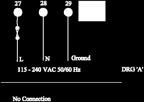
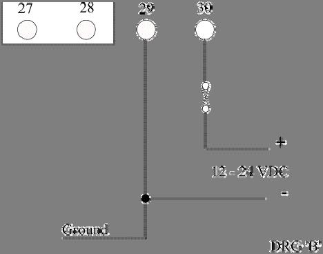
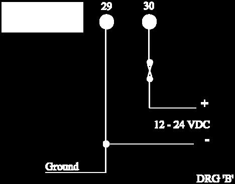
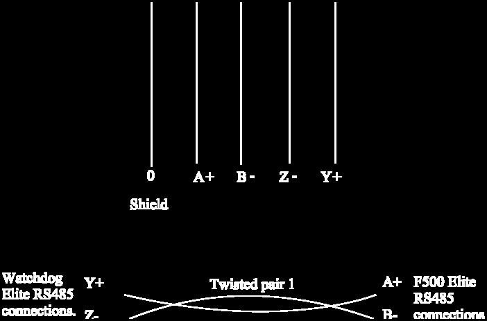
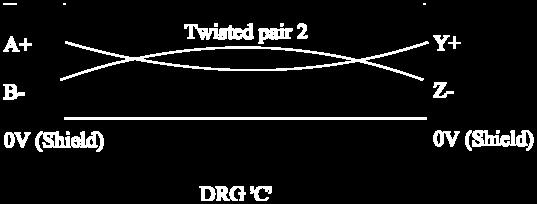
6 2. INSTALLATION INSTRUCTIONS The Control Unit The Control Unit box should be installed in a suitable control or starter switch room. The box should have sufficient space to open the lid for wiring. The Control Unit is susceptible to static voltage. Connection of a clean ground to terminal 29 is essential for optimum performance. Prior to this connection, static handling precautions should be taken. 3 ELECRICAL WIRING Refer to Drawings A, B, C & E When installing the equipment in an area which is likely to be hazardous from Ignitable Dusts, use liquid tight conduit and fittings and follow all local codes. 4 OPERATING INSTRUCTIONS The Fieldbus Adapter is a self contained unit and there are a number of user configurable options. The adapter is equipped with three communications ports; RS232, RS485 and Modbus RTU. The RS232 is a simple interface which can be used for diagnostics purposes. The data from this port is formatted to work with a VT100 display terminal. Any terminal or terminal emulator capable of supporting the VT series or compatible commands can be used with this port although the data has been optimised to work with VT100. The RS232 port operates at a fixed data rate of 9600, N, 8, 1. The RS485 port is a four wire, twin twisted pair full duplex serial port and has been specifically configured to work with the Watchdog communications network. You should not connect any other devices to this port unless you wish to monitor the Watchdog data directly. If this is the case then contact your supplier for details relating to the Watchdog communications protocol. The Modbus RTU port conforms to the Modbus interface specification for RS232 and RS485 two wire communications 6
7 The above diagram shows the location of the main parts of the Modbus RTU module. Following is a representation of the configuration switch for the F500 Modbus RTU interface. Modbus address selection switches. (See Appendix A for further detail.) 7
 position. If this should not be the termination node then set these switches to the OFF (up) position.")
8 Baud rate selection Parity selection Terminator selection Terminator selection The Modbus RTU module is equipped with an internal termination resistor network which is enabled when the two strapped switches are in the ON (down) position. If this should not be the termination node then set these switches to the OFF (up) position. The equivalent resistor network will terminate the RS485 cable with a 120 Ohm resistor. When using the RS-485 option you may need to use terminations resistors if the F500 it at the end of the Modbus communications cable. Switch bank 1 on the far left is used to select the termination resistors. 8


9 The Modbus RTU connections are shown below. The statuses LED s are grouped in a single block of four and indicate the following. Led 1 - Processing Colour Frequency Description Off Off No query is being handled by the module at the moment Green Flashing The module is receiving a query and is building a response Led 2 Bus Error Colour Frequency Description Red Steady on Bus Error (More than 1/10 of all queries have incorrect CRC) Off Off Normal operation, or module not initialised Led 3 Bus Ready Colour Frequency Description Green Steady on Bus is ready (Normal Operation) Red Steady on Bus timeout error Off Off Module is not initialised correctly 9
 Colour Frequency Description Off Off The module is not receiving power Green 0.5 Sec Flash The module is powered but not yet initialised Green 1.")
10 Led 4 Hardware setting status Colour Frequency Description Off Off The Modbus switch settings are ok and in use Red Steady On Modbus switches are set to an illegal state Watchdog Led (see the diagram on page 5) Colour Frequency Description Off Off The module is not receiving power Green 0.5 Sec Flash The module is powered but not yet initialised Green 1.0 Sec Flash The module is powered and correctly initialised Red Steady On The module has detected an internal fault condition The data may be read from the F500 using the Read Input Registers or Read Holding Registers Watchdog Address Input Words Input Byte The Watchdog data is automatically read for up to 10 controllers. The data returned is processed and stored in the following format. The position of the data is fixed within the input data table All the values are stored in Hexadecimal Number of Watchdogs detected this time (Byte 1,0) Once only Watchdog current speed (Byte 3,2) Watchdog current operating status (Byte 5,4) Under speed alarm and stop in % (Byte 7,6) Over speed alarm and stop in % (Byte 9,8) Current calibration value in PPM (Byte 11,10) Display scaling factor (Byte 13,12) NTC Temperature 1 and 2 (Byte 15, 14) NTC Temperature 3 and 4 (Byte 17, 16) NTC Temperature 5 and 6 (Byte 19, 18) NTC temperature sensor status 1 and 2 (Byte 21,20) NTC temperature sensor status 3 and 4 (Byte 23,22) NTC temperature sensor status 5 and 6 (Byte 25,24) Sensor 1 and sensor 2 alarm level (Byte 27,26) Sensor 3 and sensor 4 alarm level (Byte 29,28) Sensor 5 and sensor 6 alarm level (Byte 31,30) Number of sensors in use (Byte 33), Relay status (Byte 32) Persistent alarm value (Byte 35), update counter (Byte Although data is returned in a word format, much of the data is in either byte pairs (2 bytes per word) or as two single bytes; more on this later. Word 0 (Byte 1) is used to indicate the number of Watchdogs that are responding to the request for data. Word 0 (Byte 0) is unused. This only occurs once in the entire table. The remaining data stored in the input bytes is constructed as follows.
11 The data from each Watchdog is stored in 17 consecutive words (or 34 bytes) of data. The first two bytes of the group of 34 (e.g. 3 & 2) represent the Watchdog speed. The second two bytes of the group of 34 (e.g. 5 & 4) represent the Watchdog status. The Watchdog speed is encoded in the following manner. Four hexadecimal digits are used to represent the measured speed for the Watchdog. The rightmost three and a half are the main body of the speed and the upper half of the fourth is the position of the decimal place within the information. If the most significant two bits are 00 then decoding of the speed is not required. If the two bits are 01, then the resulting value should be divided by 10 and if the two bits are 10 then the speed should be divided by 100. The top two bits should never be 11 as this has no meaning. Bit Bit Description (e.g. most significant bits of the first speed byte 3) Bits 5-0 of the first byte and the whole second represent the speed. 0 1 Same as above but the speed and should be divided by Same as above but the speed and should be divided by Not used. An example of this can be seen below. Watchdog speed = 6E (e.g. byte 3) & 1E (e.g. byte 2). The leftmost digit (6) = 0110 in binary which can be separated into 01 (bits 7 and 6) for speed scaling and 10 (bits 5 and 4) for the upper speed digit. If you strip off bits 7 and 6 you are left with a decoded value of 2E & 1E for the speed and 01 or divide by 10 for the scaling. The speed 2E1E converted to decimal = and then divided by 10 results in an actual speed of By default the Watchdog will display speed in pulses per minute but it can be scaled to display any value required, refer to the Watchdog manual for further detail. The Watchdog status is encoded as described in the following manner. Two data bytes are used to represent the status for the Watchdog. The first status byte (e.g. byte 5) is the status code and the second byte (e.g. byte 4) represents any data which is associated with the status code. All data is in hexadecimal. Status Code (Byte 5) Status Data (Byte 4) What it means. 09 % Complete Watchdog is calibrating (% complete). 0F - Elevator is stopped due to persistent belt slip Elevator is stopped due to persistent over calibration Misalignment detected on Top & Bottom sensors Elevator is stopped and is ready to run (Normal stop condition) 23 Start-up Delay Elevator is accelerating. (xx seconds remain) In seconds 24 Speed % Elevator running within programmed limits. 25 Speed % Stop relay has been de-energised (Fault stop condition) 27 Time to alarm In seconds Misalignment detected. (xx seconds to alarm) 11
12 2A Time to alarm In seconds Over speeding: Alarm relay about to de-energise (xx seconds to alarm) 2D - Misalignment detected at the top of the elevator. 2F Time to stop In seconds Over speeding: Stop relay about to de-energise (xx seconds to stop) 31 - Speed display is over range: check the scaling factor Start elevator to commence calibration procedure Watchdog has detected an internal fault. 39 Time to alarm Belt slipping. (xx seconds to alarm) In seconds 3A Time to stop In seconds Belt slipping: Stop relay about to de-energise. (xx seconds to stop) 3B - Elevator stopped due to lack of acceleration. 3C Time to stop Persistent alarm. (xx seconds to alarm) In seconds 3D - Elevator stopped: Speed has exceeded over speed limit. 3E - Interlock signal off, waiting for zero speed. 3F - Elevator stopped: Persistent alarm condition Elevator stopped: Severe under speed Watchdog is not calibrated: Please see the manual Misalignment detected at the bottom of the elevator Wrong access code used when changing setup. 46 Speed % Elevator speed less than alarm level (slipping) 47 Speed % Elevator speed more than alarm level ( Over speeding) 49 - Suspected open circuit or faulty PTC bearing temperature sensor. 4A - Suspected fault on one or more MAS. Could be mains pickup. 4E - Plug switch is open PTC Hot bearing at zone PTC Hot bearing at zone PTC Hot bearing at zone PTC Hot bearing at zone PTC Hot bearing at zone PTC Hot bearing at zone HBS is open circuit at zone HBS is open circuit at zone HBS is open circuit at zone HBS is open circuit at zone 4 5A - HBS is open circuit at zone 5 5B - HBS is open circuit at zone 6 An example of the status code might be The first status byte (byte 5) 24 show that the equipment is running within the specified alarm limits and the second status byte (byte 4) 63 indicate that the speed is 99% if it s calibrated value. Where a value is not 12
13 shown or a - is used in the table, this indicates that any data present in this field should be ignored. Several different conditions may occur at the same time whilst the Watchdog is operating. If the Watchdog is running within calibrated range but also detects a motion sensor fault then the information returned may look something like this Running at 99% of calibrated speed. Followed three seconds later by 2D-- Misalignment detected at the top of the elevator. Followed three seconds later by 3CAA Persistent alarm, 170 seconds to go. The messages would then repeat with any new values in the status data field. Due to some limitations in the speeds involved in updating the Watchdog information, rapid changed of data could be missed or be present for only a very short period of time. If the Watchdog is placed in one of the two test modes, the messages below will be returned in the following order. Bytes 3 and 2 Bytes 5 and 4 The first two bytes show the speed data and the second two bytes show the status and status data. xx & xx 06 & xx Over speed Stop as a percentage of calibrated speed. xx & xx 05 & xx Over speed Alarm as a percentage of calibrated speed. xx & xx 02 & xx The actual calibrated speed xx & xx 03 & xx Under speed Alarm as a percentage of calibrated speed. xx & xx 04 & xx Under speed Stop as a percentage of calibrated speed & -- Performing internal test C & -- Testing the Alarm relay D & -- Testing the Stop relay. Codes 4C and 4D are only returned if the extended test is in operation. Under speed alarm and stop in % (Byte 7, 6) These two bytes show (in % of calibrated speed) the under speed alarm and stop levels. These represent the point at which the Watchdog will generate an alarm or stop condition. Example, if byte 7 is 0A and byte 6 is 14 then this means that the Watchdog will generate an under speed alarm at 10% (0A) below calibrated speed and will generate a stop condition at 20% (14) below the calibrated speed. Over speed alarm and stop in % (Byte 9, 8) These two bytes show (in % of calibrated speed) the over speed alarm and stop levels. These represent the point at which the Watchdog will generate an alarm or stop condition. Example, if byte 7 is 0A and byte 6 is 14 then this means that the Watchdog will generate an over speed alarm at 10% (0A) above calibrated speed and will generate a stop condition at 20% (14) above the calibrated speed. 13
14 Current calibration value in PPM (Byte 11, 10) These two bytes represent the current calibration speed value in Pulses Per Minute (Default). The representation can be changed to other scaled values by using the display scaling value below. Refer to the Watchdog manual for further details about display scaling. Display scaling factor (Byte 13, 12) These two bytes contain a value which is used by the Watchdog to scale the information on the display into a format which represents more accurately what the elevator is doing. The default scaling factor (04B0) results in the display showing the current speed in PPM. Refer to the Watchdog manual for further details about display scaling. NTC Temperature 1 and 2 (Byte 15, 14) These two bytes show the actual temperature of temperature sensors 1 & 2. The values are in Dec C or Deg F according to the settings on the Watchdog. Refer to the Watchdog manual NTC section for more detail. NTC Temperature 3 and 4 (Byte 17, 16) & NTC Temperature 5 and 6 (Byte 19, 18) See the detail above for temperature sensors 1 and 2 NTC temperature sensor status 1 and 2 (Byte 21, 20) These two bytes show the current status of temperature sensors number 1 & 2. If byte 21 is 0 then sensor 1 is NORMAL If byte 21 is 1 then the temperature of sensor 1 is HIGH so an alarm has been generated. If byte 21 is 2 then sensor 1 may be OPEN circuit If byte 21 is 3 then sensor 1 may be SHORT circuit NTC temperature sensors 2 to 6 operate in an identical manner as described for sensor 1 above. Sensor 1 and sensor 2 alarm level (Byte 27,26) These two bytes represent the alarm value for the temperature sensor. The default values for this alarm level are 9E (158) when measuring in Deg F and 50 (80) when measuring in Deg C. Refer to the Watchdog manual for further detail regarding this value. Sensor 3 and sensor 4 alarm level (Byte 29, 28) & Sensor 5 and sensor 6 alarm level (Byte 31, 30) operate in an identical manner as described above. Number of sensors in use (Byte 33) Byte 33 shows the total number of NTC temperature sensors that are currently being monitored by the Watchdog. This value ranges from 0 to 6. See the watchdog manual for further detail. 14

15 Relay status (Byte 32) This byte contains information relating to the status of the Watchdog LED s and Relays. Although the byte is represented in Hexadecimal converting it to binary helps to explain the contents a little better. 0000:0000 The left hand four bits are always 0000 and can be ignored. 0000:0000 The right hand four bits contain the following information. : This bit indicates the condition of the STOP Led (1=ON: 0=OFF) : This bit indicates the condition of the ALARM Led (1=ON: 0=OFF) : This bit indicates the condition of the STOP Relay (1=ON: 0=OFF) : This bit indicates the condition of the ALARM Relay (1=ON: 0=OFF) Not used and always 0000 When a relay is considered to be ON we mean energized and when OFF we mean deenergized. 0000:0000 = 00 then no conditions exist 0000:0010 = 02 then the alarm Led is on 0000:1010 = 0A then the alarm Led and Alarm Relay are active 0000:0011 = 03 then both Led s are on and both Relays are off (de-energized) Persistent alarm value NTC only (Byte 35) This is how long the temperature alarm will take in seconds before stopping the elevator. The default value is B4 180 seconds. If this value reaches 0 then the elevator will be stopped. Update counter (Byte 34) Every time the F500 successfully receives information from the chosen watchdog, then this counter value will be incremented by 1. The watchdog treats serial communications as low priority so occasionally requests for data can be ignored. It is advisable to keep checking this value so as to know when new data has arrived in the F500. The counter will increment from 0 to 255 and then return to 0 again in a continuous loop. Below is an example of the data returned when the F500 is polling Watchdogs Words 1 to 17 (pink) represent Watchdog 1. These are currently all 0 because watchdog 1 isn t present at this time. Words 18 to 34 (green) represent Watchdog 2. Word 18 15
16 which is 0484 HEX tells us that the Watchdog is currently running at 1156 pulses per minutes. Word 19 which is 2465 HEX tells us that the Watchdog is running (24) at 101% (65) of the calibrated speed. The remainder of the information in the example can be decoded using the information as previously described. Words 35 to 51 (blue) represent Watchdog 3. Word 35 which is 0000 HEX tells us that the Watchdog is currently NOT running. Word 36 which is 4100 HEX tells us that the Watchdog is in fact NOT calibrated (41), see the Watchdog manual for more detail about calibration. Diagnostics Display. The F500 Elite is equipped with a simple RS232 serial interface. This interface can be used to monitor the communications with the Watchdog Elite. The information displayed contains diagnostic data about the Fieldbus module and Watchdog number 1. A VT100 or compatible display terminal should be used to display the information. Above is an example screen image from the diagnostics display. The information displayed will vary slightly dependent upon the fieldbus interface used. CBU Version = X.XX API Version = X.XX FBI Version = X.XX ABI Version = X.XX This is the control base unit software version. This is the application interface software version. This is the Fieldbus interface software version. This is the AnyBus interface software version. Fieldbus type = Modbus RTU This describes the type of Fieldbus module which is installed in the F500 Elite. If the Fieldbus module is faulty some or all of this data will change to suggest which area may be at fault. For example, FBI version number might 16
17 become An unusually large number such as this is not usually associated with a normally functioning module and would suggest that the Fieldbus interface controller has failed. In the event of this or any other fault, contact your supplier. The sequence S2468E indicated that the system has initialised correctly, a deviation from this indicates that one or more parts of the initialisation process has failed. If this is the case, recycle power and see if this clears the problem. If you still have problems with the initialisation of the unit contact your supplier and tell them what you see on the diagnostics display. The main area of the display shows the complete data from Watchdog address number 1 as described on pages 8 to 13 of this manual. Diagnostics LED. Located on the main circuit board, just above the RS485 connections to the Watchdog you will find an LED indicator (usually RED). This indicator will flash every time the F500 attempts to communicate with the Watchdogs. The LED will normally flash at a consistent rate followed by a very short pause. The short pause indicates that the F500 is updating the information which it stores internally. A significant deviation from this sequence is an indication that there is a problem. If this happens, contact your supplier for further information. 17
18 CHECK LIST For problems after initial start-up 1. Is there excessive interference on the electrical power supply? Power conditioners and surge (spike) suppressor may have to be fitted. 2. Has the wiring for the Watchdog and Fieldbus been routed away from power cables? 3. Is the F500 Elite circuit properly grounded? 4. Is the Micro-processor control unit overheating, if so mount in temperaturecontrolled environment of maximum temperature 104 F (40 C). 5. Check that high powered Walkie Talkie radios are not operated immediately near the control unit or Watchdogs as this will affect the performance. 6. Check that the communications/power cable is connected correctly and in accordance with DRG A,B,C and E. 7. Check that there is no exception status reported. 8. If only part of the diagnostics data is displayed on the terminal screen then turn the F500 Elite off then back on again without removing power to the display terminal. 9. If the Watchdogs are not responding or are intermittent, check that the termination resistors are correctly fitted. 18
19 CONTACT INFORMATION 19

20 20


21 21

22 On more recent versions of the F500 TB1 may be a standard 9 pin Dee connector. This Dee connector is designed to work with a standard 9 pin to 9 pin serial lead for monitoring the F Connect 120 OHM ½ watt resistors between A+ and B- and between


23 Maximum of 10 Watchdogs PC or Other Ethernet Device Modbus RTU //
24 Appendix A Modus RTU address switch table (SW1 is MSB SW7 is LSB)
25 WARRANTY INFORMATION 1. EXCLUSIVE WRITTEN LIMITED WARRANTY ALL PRODUCTS SOLD ARE WARRANTED BY THE COMPANY (4B COMPONENTS LIMITED, (4B) BRAIME ELEVATOR COMPONENTS LIMITED, AND (4B) S.E.T.E.M. Sarl) HEREIN AFTER REFERRED TO AS 4B TO THE ORIGINAL PURCHASER AGAINST DEFECTS IN WORKMANSHIP OR MATERIALS UNDER NORMAL USE FOR ONE (1) YEAR AFTER DATE OF PURCHASE FROM 4B. ANY PRODUCT DETERMINED BY 4B AT ITS SOLE DISCRETION TO BE DEFECTIVE IN MATERIAL OR WORKMANSHIP AND RETURNED TO A 4B BRANCH OR AUTHORIZED SERVICE LOCATION, AS 4B DESIGNATES, SHIPPING COSTS PREPAID, WILL BE, AS THE EXCLUSIVE REMEDY, REPAIRED OR REPLACED AT 4B S OPTION. 2. DISCLAIMER OF IMPLIED WARRANTY NO WARRANTY OR AFFIRMATION OF FACT, EXPRESSED OR IMPLIED, OTHER THAN AS SET FORTH IN THE EXCLUSIVE WRITTEN LIMITED WARRANTY STATEMENT ABOVE IS MADE OR AUTHORIZED BY 4B. 4B SPECIFICALLY DISCLAIMS ANY LIABILITY FOR PRODUCT DEFECT CLAIMS THAT ARE DUE TO PRODUCT MISUSE, ABUSE OR MISAPPLICATIONS, AS AUTHORIZED BY LAW, 4B SPECIFICALLY DISCLAIMS ALL WARRANTIES THAT THE PRODUCT IS FIT OR MERCHANTABLE FOR A PARTICULAR PURPOSE. 3. NO WARRANTY BY SAMPLE OR EXAMPLE ALTHOUGH 4B HAS USED REASONABLE EFFORTS TO ACCURATELY ILLUSTRATE AND DESCRIBE THE PRODUCTS IN ITS CATALOGS, LITERATURE, AND WEBSITES, SUCH ILLUSTRATIONS AND DESCRIPTIONS ARE FOR THE SOLE PURPOSE OF PRODUCT IDENTIFICATION AND DO NOT EXPRESS OR IMPLY A WARRANTY AFFIRMATION OF FACT, OF ANY KIND OR A WARRANTY OR AFFIRMATION OF FACT THAT THE PRODUCTS WILL CONFORM TO THEIR RESPECTIVE ILLUSTRATIONS OR DESCRIPTIONS. 4B EXPRESSLY DISCLAIMS ANY WARRANTY OR AFFIRMATION OF FACT, EXPRESSED OR IMPLIED, OTHER THAN AS SET FORTH IN THE EXCLUSIVE WRITTEN LIMITED WARRANTY STATEMENT ABOVE, INCLUDING, WITHOUT LIMITATION, THE IMPLIED WARRANTIES OF MERCHANTABILITY AND FITNESS FOR A PARTICULAR PURPOSE. 4. LIMITATION OF DAMAGES ANY LIABILITY FOR CONSEQUENTIAL, INCIDENTAL, SPECIAL, EXEMPLARY, OR PUNITIVE DAMAGES, OR FOR LOSS OF PROFIT WHETHER DIRECT OR INDIRECT, IS EXPRESSLY DISCLAIMED. 25
F500 Elite. FIELDBUS ADAPTER. Watchdog (NTC) Elite to DeviceNet communications. (Software Version 1.1.x)
 Elite to DeviceNet communications. (Software Version 1.1.x)") F500 Elite. FIELDBUS ADAPTER. Watchdog (NTC) Elite to DeviceNet communications. (Software Version 1.1.x) Approvals: Suitable for use in Hazardous Locations CL II Div 1 GPS E, F & G (CANADA ONLY) CL II
F500 Elite. FIELDBUS ADAPTER. Watchdog (NTC) Elite to DeviceNet communications. (Software Version 1.1.x) Approvals: Suitable for use in Hazardous Locations CL II Div 1 GPS E, F & G (CANADA ONLY) CL II
WDB2 Series Bearing Temperature Sensor
 WDB2 Series Bearing Temperature Sensor Dear 4B Customer: Congratulations on your purchase. 4B appreciates your business and is pleased you have chosen our products to meet your needs. Please read in its
R500E MANUAL (Software Version 2.0)
") R500E MANUAL (Software Version 2.0) ONTENTS INTRODUTION 1 SPEIFIATIONS 2 INSTALLATION INSTRUTIONS 3 ELETRIAL WIRING 4 HEKLIST 5 ONTAT INFORMATION DRAWINGS D E F G GENERAL INTERONNETION DIAGRAM R500 RELAY
R500E MANUAL (Software Version 2.0) ONTENTS INTRODUTION 1 SPEIFIATIONS 2 INSTALLATION INSTRUTIONS 3 ELETRIAL WIRING 4 HEKLIST 5 ONTAT INFORMATION DRAWINGS D E F G GENERAL INTERONNETION DIAGRAM R500 RELAY
OPERATION MANUAL Part No. s - MAG2000, MAG2000M
 Mag-Con MAGNETIC CONNECTOR FOR THE WHIRLIGIG TARGET / BRACKET/ GUARD WARNING STRONG MAGNET! Can be harmful to pacemaker wearers and others with medical implants. U.S. Patent #6,964,209 INSTALLATION INSTRUCTIONS
A400E MANUAL A4004V4C & A4004V46C. Important: This document should be read carefully before commencing installation
 A400E MANUAL A4004V4C & A4004V46C Important: This document should be read carefully before commencing installation Rev4 CONTENTS APPROVALS INTRODUCTION 1 SPECIFICATIONS 1.1 CONTROL UNIT 1.2 ELEVATOR ALIGNMENT
OPERATION MANUAL Part No s. P8003V10C, P8004V10C
 P8003/P8004 Proxswitch INDUCTIVE PROXIMITY SENSOR C US APPROVED Class II Div. 1 INSTALLATION INSTRUCTIONS OPERATION MANUAL Part No s. P8003V10C, P8004V10C www.go4b.com/usa TABLE OF CONTENTS CUSTOMER SAFETY
OPERATION MANUAL Part No. T4004NV46C / T4004NV4C
 T400N Elite - Hotswitch BEARING TEMPERATURE MONITOR C US INSTALLATION INSTRUCTIONS OPERATION MANUAL Part No. T4004NV46C / T4004NV4C www.go4b.com/usa TABLE OF CONTENTS CUSTOMER SAFETY RESPONSIBILITIES
OPERATION MANUAL Part No. MIL8001V4C
 Milli-Speed Switch 4-20 ma OUTPUT UNDERSPEED SENSOR C US APPROVED Class II Div. 1 INSTALLATION INSTRUCTIONS OPERATION MANUAL Part No. MIL8001V4C www.go4b.com/usa TABLE OF CONTENTS CUSTOMER SAFETY RESPONSIBILITIES
T500 Elite MANUAL (Software Version 3.0.9)
") T500 Elite MANUAL (Software Version 3.0.9) Document Revision 1 February 2010 CONTENTS INTRODUCTION 1 SPECIFICATIONS 1.1 CONTROL UNIT 1.2 BEARING TEMPERATURE SENSORS 1.3 TEMPERATURE NODE TN4e. 1.4 R500
T500 Elite MANUAL (Software Version 3.0.9) Document Revision 1 February 2010 CONTENTS INTRODUCTION 1 SPECIFICATIONS 1.1 CONTROL UNIT 1.2 BEARING TEMPERATURE SENSORS 1.3 TEMPERATURE NODE TN4e. 1.4 R500
USER MANUAL FOR OPERATING SYSTEM
 P2262 ALARM PANEL USER MANUAL FOR OPERATING SYSTEM 21765-07 September 1999 Associated Controls (Aust) PTY. LTD. 29 Smith Street, Hillsdale, NSW, 2036. PH (02) 9311 3255, FAX (02) 9311 3779 Page 1 of 177
Centaur TM II Cube Slave Alarm Signalling Equipment INSTALLATION GUIDE
 Centaur TM II Cube Slave Alarm Signalling Equipment INSTALLATION GUIDE General Description This guide provides a summary for installing and configuring the Centaur TM Cube Slave Alarm Signalling Equipment
Controllers. Instruction Manual WARNING
 Controllers Instruction Manual WARNING THIS MANUAL MUST BE CAREFULLY READ BY ALL INDIVIDUALS WHO HAVE OR WILL HAVE THE RESPONSIBILITY FOR INSTALLING, USING OR SERVICING THIS PRODUCT. Like any piece of
Remote Relay Module (RRM)
") Remote Relay Module (RRM) Instruction Manual WARNING THIS MANUAL MUST BE CAREFULLY READ BY ALL INDIVIDUALS WHO HAVE OR WILL HAVE THE RESPONSIBILITY FOR INSTALLING, USING OR SERVICING THIS PRODUCT. Like
Remote Relay Module (RRM) Instruction Manual WARNING THIS MANUAL MUST BE CAREFULLY READ BY ALL INDIVIDUALS WHO HAVE OR WILL HAVE THE RESPONSIBILITY FOR INSTALLING, USING OR SERVICING THIS PRODUCT. Like
P2267 NETWORK INTERFACE
 P2267 NETWORK INTERFACE USER MANUAL FOR OPERATING SYSTEMS: 22031-03 23636-01 October 2009 Associated Controls (Australia) Pty. Limited 2-4 Norfolk Road Greenacre, NSW, 2190. PH +61 2 9642 4922, FAX +61
RS485 MODBUS Module 8AI
 Version 1.4 15/04/2013 Manufactured for Thank you for choosing our product. This manual will help you with proper support and proper operation of the device. The information contained in this manual have
Instruction Manual WARNING
 Controllers Instruction Manual WARNING THIS MANAUL MUST BE CAREFULLY READ BY ALL INDIVIDUALS WHO HAVE OR WILL HAVE THE RESPONSIBILITY FOR INSTALLING, USING OR SERVICING THIS PRODUCT. Like any piece of
MODEL DPS1 Heated Dew Point Measuring System OPERATORS MANUAL
 MODEL DPS1 Heated Dew Point Measuring System OPERATORS MANUAL 19 Brigham Street Unit #8 Marlborough, MA USA 01752 Tel: (508) 263-5900 (800) 276-3729 Fax: (508) 486-9348 E-mail: h2o@edgetech.com www.edgetech.com
AUTOMATION. Operator s Manual RST Series Web Enabled Input Module. Rev. A2, 1/12
 AUTOMATION P R O D U C T S GROUP, INC. Operator s Manual RST-5000 Series Web Enabled Input Module Rev. A2, 1/12 Tel: 1/888/525-7300 Fax: 1/435/753-7490 www.apgsensors.com E-mail: sales@apgsensors.com RST-5000
LINEAR HEAT DETECTION CABLE DURÁN-SAFE
 LINEAR HEAT DETECTION CABLE DURÁN-SAFE Installation & User Manual 2018 DURAN ELECTRONICA S.L. - All rights reserved www.duranelectronica.com I-manSAFECABLE-v05 TABLE OF CONTENTS Pages 1. INTRODUCTION...
Modbus TCP/IP Option Instruction Manual
 W A L C H E M An Iwaki America Company WebMaster Modbus TCP/IP Option Web Master WIND Modbus TCP/IP Option Instruction Manual s825v008 and higher Five Boynton Road Hopping Brook Park Holliston, MA 01746
Radiant Thermostat 519
 106103_dl_02 Radiant Thermostat 519 Installation & Operation Manual Introduction The Radiant Thermostat 519 accurately controls the room and/or floor temperature for a hydronic heating zone using Pulse
DiMM Unit. LST Digital Interface Monitor Module (LST-DiMM) MAN3109
 MAN3109") LST Digital Interface Monitor Module (LST-DiMM) MAN3109 TABLE OF CONTENTS: Page No. 1 Important Guidelines... 3 2 General Description... 4 Digital Interface Monitor Module... 4 3 Specifications... 5 Leader
LST Digital Interface Monitor Module (LST-DiMM) MAN3109 TABLE OF CONTENTS: Page No. 1 Important Guidelines... 3 2 General Description... 4 Digital Interface Monitor Module... 4 3 Specifications... 5 Leader
OPERATION MANUAL Part No. s - WDC4V4C, WDC4V46C Hardware Version R4 - Software Version 4.7.X
 Watchdog Super Elite BUCKET ELEVATOR & BELT CONVEYOR HAZARD MONITORING SYSTEM C US INSTALLATION INSTRUCTIONS OPERATION MANUAL Part No. s - WDC4V4C, WDC4V46C Hardware Version R4 - Software Version 4.7.X
SEC 2000 Millenium Infrared Gas Detector
 SEC 2000 Millenium Infrared Gas Detector Instruction and Operation Manual Sensor Electronics Corporation 5500 Lincoln Drive Minneapolis, Minnesota 55436 USA (952) 938-9486 Fax (952) 938-9617 Email: sales@sensorelectronic.com
CO2 Sensor User and Installation Guide
 CO2 Sensor User and Installation Guide P/N: 110227 WARRANTY & LIMITATION OF LIABILITY 1. ROTEM warrants that the product shall be free of defects in materials or workmanship and will conform to the technical
SPI Communications Option
 www.conairnet.com USERGUIDE IMD021/1297 SPI Communications Option Corporate Office: 412.312.6000 l Instant Access 24/7 (Parts and Service): 800.458.1960 l Parts and Service: 814.437.6861 The SC Carousel
GG-EM ENTRANCE MONITOR. Installation and Operation Manual
 GG-EM ENTRANCE MONITOR Installation and Operation Manual 2 GG-EM Warning Use this product only in the manner described in this manual. If the equipment is used in a manner not specified by Calibration
Sentry LIQUID LEVEL ALARM MODEL 100 OPERATING MANUAL.
 Sentry LIQUID LEVEL ALARM MODEL 100 OPERATING MANUAL www.aquaticsentry.com TABLE OF CONTENTS 1. SAFETY PRECAUTIONS... 3 2. APPLICATION... 3 2.1 HIGH Liquid Level Alarm 2.2 LOW Liquid Level Alarm 3. INSTALLATION...
TraceNet ECM Series Control System
 TraceNet ECM Series Control System ECM Operating Guide Thermon Manufacturing Company TraceNet is a registered trademark of Thermon Manufacturing Company. ECM Operating Guide 2014, 2015 Thermon Manufacturing
Models LBW-420-LEL (24 VDC powered) Ammonia Leak Detector
 Ammonia Leak Detector") Models LBW-420-LEL (24 VDC powered) Ammonia Leak Detector CAUTION & SYMBOL DEFINITIONS: CAUTION: Gives detailed description of different situations to avoid or not avoid for the proper operation of the
Models LBW-420-LEL (24 VDC powered) Ammonia Leak Detector CAUTION & SYMBOL DEFINITIONS: CAUTION: Gives detailed description of different situations to avoid or not avoid for the proper operation of the
Table of Contents SECTION PAGE SECTION 1 INTRODUCTION Description Features Models... SECTION 2 RS-232 COMMUNICATIONS...
 SECTION Table of Contents SECTION 1 INTRODUCTION...................... 1.1 Description............................... 1.2 Features................................. 1.3 Models..................................
MODEL QTS-1800 SERIES WALL MOUNT DIGITAL AND ANALOG TRANSMITTER/SENSOR
 MODEL QTS-1800 SERIES WALL MOUNT DIGITAL AND ANALOG TRANSMITTER/SENSOR INSTALLATION OPERATION AND MAINTENANCE MANUAL QUATROSENSE ENVIRONMENTAL LTD. 5935 OTTAWA STREET, PO BOX 749 RICHMOND, ONTARIO CANADA
ACCURATE ELECTRONICS INC PO BOX SW HALL BLVD BEAVERTON OR USA FAX
 Page 1 of 10 Model 10807800 January 2014 ACCURATE ELECTRONICS INC PO BOX 1654 97075-1654 8687 SW HALL BLVD 97008 BEAVERTON OR USA 503.641.0118 FAX 503.646.3903 WWW.ACCURATE.ORG Practice Section 10807800
User s Guide. CN606 / 612 AC Series & CN606 / 612 DC Series CONTRONAUTICS INCORPORATED. Table of Contents.
 User s Guide SECTION Table of Contents Page SECTION 1 INTRODUCTION............ 2 1.1 Description...................... 2 1.2 Features........................ 2 1.3 Models........................ 3 SECTION
D-TEK O P E R A T I N G I N S T R U C T I O N S V E HI C L E L O O P DETECTOR Johnston Parkway, Cleveland, Ohio 44128
 O P E R A T I N G I N S T R U C T I O N S D-TEK V E HI C L E L O O P DETECTOR 4564 Johnston Parkway, Cleveland, Ohio 44128 P. 800 426 9912 F. 216 518 9884 Sales Inquiries: salessupport@emxinc.com Technical
Instruction Manual Model Backup Switch, 1 for 8
 Instruction Manual Model 2582-282 Backup Switch, 1 for 8 December 2011, Rev. 0 MODEL 2582 SWITCH CROSS TECHNOLOGIES INC. SWITCH ALARM PSA PSB ALARM OFFLINE ONLINE UNIT STATUS 1 2 3 4 5 6 7 8 BU PROT MODE
Carbon Monoxide (CO) Detecting Ventilation Fan Controller Model 120VC Single Relay (100/25 PPM) (200/35 PPM)
 Detecting Ventilation Fan Controller Model 120VC Single Relay (100/25 PPM) (200/35 PPM)") Carbon Monoxide (CO) Detecting Ventilation Fan Controller Model 120VC Single Relay 905-0005-01 (100/25 PPM) 905-0005-02 (200/35 PPM) 1. INTRODUCTION Your COSTAR VC carbon monoxide detecting ventilation
Carbon Monoxide (CO) Detecting Ventilation Fan Controller Model 120VC Single Relay 905-0005-01 (100/25 PPM) 905-0005-02 (200/35 PPM) 1. INTRODUCTION Your COSTAR VC carbon monoxide detecting ventilation
T500 Elite - Hotbus Plant Wide Monitoring System for Bucket Elevators & Conveyors
 Plant Wide Monitoring System for Bucket Elevators & Conveyors APPLICATION Combined belt alignment, belt speed, continuous bearing temperature, pulley alignment, level and plug condition monitor for bucket
Long Range Radio Alarm Transmitter
 TM Long Range Radio Alarm Transmitter INSTALLATION MANUAL Version 1.3W FEATURES Transmits alarm information to a long range radio network Varitech Transmission Format Note: If automatic SIA is used in
UNC100 Integra Manual
 UNC100 Integra Manual New Generation Building Security July 30, 2014 V1.2 Copyright Notice Copyright 1995-2014 by All rights reserved Worldwide. Printed in Canada. This publication has been provided pursuant
Models NFPA 1221-A, NFPA 1221-B Public Safety DAS Annunciator Panel. Revision E 61117
 Models NFPA 1221-A, NFPA 1221-B Public Safety DAS Annunciator Panel Revision E 61117 CAUTION: (Read This First) This panel has been designed to make it nearly bullet proof to mistakes made when wiring
FW-RA-LED Remote Multiplex Annunciator Panels
 FW-RA-LED Remote Multiplex Annunciator Panels WIRING and INSTALLATION INSTRUCTION LNOTICE All information, documentation, and specifications contained in this manual are subject to change without prior
ModSync Sequencing System Installation & Operation Manual. For use with Fulton Steam Boilers.
 ModSync Sequencing System Installation & Operation Manual For use with Fulton Steam Boilers. Revision 3.0 8/21/2008 - 2 - Table of Contents Introduction Page 4 Features Page 4 Sequence of Operation Page
SC-6 Six Supervised Control Module
 INSTALLATION AND MAINTENANCE INSTRUCTIONS SC-6 Six Supervised Control Module SPECIFICATIONS Normal Operating Voltage: Stand-By Current: Alarm Current: Temperature Range: Humidity: Dimensions: Accessories:
DIGITAL TEMPERATURE RELAY TR-100
 LTD Research-and-Manufacture Company DIGITAL TEMPERATURE RELAY USER S MANUAL www.novatek-electro.com - 2 - Service manual is intended for getting acquaints with hardware, operation principals, modes of
Ion Endeavor Pump Controller Digital Level Control with Pump Alternation and High Water Alarm
 Ion Endeavor Controller Digital Level Control with Alternation Page 1 of 8 General Overview The Ion Endeavor is a pump controller that senses a water level of up to 72", has a configurable water level/pump
INSTALLATION & OPERATION MANUAL
 INSTALLATION & OPERATION MANUAL Model TME- * * Balance of model number is determined by customer specifi ed limits and Setbacks. AUTOMATIC SETBACK THERMOSTAT LIGHT SENSING OR CONTACT CLOSURE FOR LOW VOLTAGE
Pump-Down Controller MODEL 4052
 Pump-Down Controller 4-20mA Input/Scalable Output Seal Fail Monitoring Duplex Pump Alternation Hand-Off-Auto Controls Dual Run-time Meters RS-485/Modbus Communications DESCRIPTION The Model 4052 Pump-Down
Silicone Rubber Heating Tape with Adjustable Thermostat Control (HSTAT Series) Instruction Manual
 Instruction Manual") Silicone Rubber Heating Tape with Adjustable Thermostat Control (HSTAT Series) Instruction Manual Read and understand this material before operating or servicing these heating tapes. Failure to understand
Silicone Rubber Heating Tape with Adjustable Thermostat Control (HSTAT Series) Instruction Manual Read and understand this material before operating or servicing these heating tapes. Failure to understand
Pioneer-R16 Gas Monitor Operator s Manual
 Pioneer-R16 Gas Monitor Operator s Manual Edition 7/2/97 RKI INSTRUMENTS, INC RKI Instruments, Inc. 33248 Central Ave, Union City, CA 94587 (510) 441-5656 Chapter 1: Description About the Pioneer-R16 Gas
Sentry LIQUID LEVEL CONTROLLER MODEL 120 OPERATING MANUAL.
 Sentry LIQUID LEVEL CONTROLLER MODEL 120 OPERATING MANUAL www.aquaticsentry.com TABLE OF CONTENTS 1. SAFETY PRECAUTIONS... 3 2. APPLICATION... 3 2.1 HIGH AND LOW LEVEL ALARM 2.2 PUMP DOWN CONTROLLER 2.3
GAS MONITOR Model Model
 Sierra Monitor Corporation 1991 Tarob Court, Milpitas, CA 95035 (408) 262-6611 (800) 727-4377 (408) 262-9042 - Fax E-mail: sierra@sierramonitor.com Web Site: www.sierramonitor.com GAS MONITOR Model 2350-00
Installation and Operations Manual
 Installation and Operations Manual H-IM-LLC February 2018 Part No. 25092501 Replaces H-IM-LLC (01/2014) Lead Lag Control System Table of Contents General Safety Information 2 Inspection 2 Warranty Statement
Mark 25 Ultrapure Water Conductivity Analyzer
 Martek Instruments, Inc. Mark 25 Ultrapure Water Conductivity Analyzer Instruction Manual WARRANTY POLICY Unless otherwise stated, MARTEK INSTRUMENTS, INC. warrants this equipment to be free from defects
OVEN INDUSTRIES, INC.
 OVEN INDUSTRIES, INC. OPERATING MANUAL Model 5C7-252 TEMPERATURE CONTROLLER With PLC Inputs Introduction Thank you for purchasing our controller. The Model 5C7-252 is an exceptionally versatile unit and
CZ-6A Six Zone Interface Module
 INSTALLATION AND MAINTENANCE INSTRUCTIONS CZ-6A Six Zone Interface Module 658 Kitimat Rd. Unit #6 Mississauga, Ontario L5N T5-800-SENSOR, FAX: 905-8-077 www.systemsensor.ca SPECIFICATIONS Normal Operating
Figure 1. Figure 2. See notes 1 and 2 below.
 273 Branchport Avenue Long Branch, N.J. 07740 (800) 631-2148 Thank you for using our products. www.wheelockinc. com INSTALLATION INSTRUCTIONS HORN SPEAKER WITH AMPLIFIER Use this product according to this
Installation, Operation & Service Manual
 Installation, Operation & Service Manual WARNING Improper installation, adjustment, alteration, service or maintenance can result in death, injury or property damage. Read the Installation, Operation and
Model Gas Alarm Panel APPLICABILITY & EFFECTIVITY. This manual provides instructions for the following Sierra Monitor products:
 Model 2102 Gas Alarm Panel APPLICABILITY & EFFECTIVITY This manual provides instructions for the following Sierra Monitor products: Model Description 2102-00 Alarm Panel 2 Channel 2102-01 Alarm Panel 2
4590 Tank Side Monitor. Service Manual. WM550 Communication Protocol. Software Versionv2.03 SRM011FVAE0808
 SRM011FVAE0808 4590 Tank Side Monitor WM550 Communication Protocol Service Manual Software Versionv2.03 www.varec.com Varec, Inc. 5834 Peachtree Corners East, Norcross (Atlanta), GA 30092 USA Tel: +1 (770)
GG-NH3 AMMONIA GAS SENSOR. Installation and Operation Manual
 GG-NH3 AMMONIA GAS SENSOR Installation and Operation Manual 2 GG-NH3 Warning Use this product only in the manner described in this manual. If the equipment is used in a manner not specified by Calibration
GG-NO2 NITROGEN DIOXIDE GAS SENSOR. Installation and Operation Manual
 GG-NO2 NITROGEN DIOXIDE GAS SENSOR Installation and Operation Manual 2 GG-NO2 Warning Use this product only in the manner described in this manual. If the equipment is used in a manner not specified by
SACE PR021/K SIGNALLING UNIT
 SACE PR021/K SIGNALLING UNIT 1SDH000559R0002 L3016 1/52 EN CONTENTS 1. GENERAL INFORMATION...4 1.1. FOREWORD...4 1.2. APPLICABLE SCENARIOS...5 2. TECHNICAL SPECIFICATIONS...6 2.1. ELECTRICAL CHARACTERISTICS...6
SAFETY INFORMATION AND WARNINGS
 This manual refers to the Model SST-3 control panel manufactured since October 31, 2013, which uses a universal (100 277 VAC; 50/60 Hz) power supply. Older units use a voltage-specific power supply and
RATIO:GUARD Model E-1S EC Monitor
 EC probe Probe tees Probe retention clips Temperature probe E-1S monitor box UNPACKING Please open and inspect your package upon receipt. Your package was packed with great care and all the necessary packing
OPERATOR S MANUAL MODEL AP15/AP15-1/AP15-2 PC-ALARM PANEL
 ap15_2manual04/22/13 Page 1 4/22/2013 1 Serial Number : Option: OPERATOR S MANUAL MODEL AP15/AP15-1/AP15-2 PC-ALARM PANEL Micro Seven, Inc. 1095-K N.E. 25th Hillsboro, OR 97124 U.S.A. phone: 503-693-6982
TTSIM-1 Sensor Interface Module
 R Sensor Interface Module Installation/Operation Guide General Information Please read these instructions and keep them in a safe place. These instructions must be followed carefully to ensure proper operation.
MODEL 4200-IR-2 (Up to 2 Sensors) MODEL 4200-IR-4 (Up to 4 Sensors) MODEL 4200-IR-6 (Up to 6 Sensors)
 MODEL 4200-IR-4 (Up to 4 Sensors) MODEL 4200-IR-6 (Up to 6 Sensors)") MODEL 4200-IR-2 (Up to 2 Sensors) MODEL 4200-IR-4 (Up to 4 Sensors) MODEL 4200-IR-6 (Up to 6 Sensors) Refrigerant Monitor User Manual Technical Support Continental North America Toll Free 1-(800) 387-9487
MODEL 4200-IR-2 (Up to 2 Sensors) MODEL 4200-IR-4 (Up to 4 Sensors) MODEL 4200-IR-6 (Up to 6 Sensors) Refrigerant Monitor User Manual Technical Support Continental North America Toll Free 1-(800) 387-9487
Carbon Monoxide Transmitter
 Introduction The CO Transmitter uses an electrochemical sensor to monitor the carbon monoxide level and outputs a field-selectable 4-20 ma or voltage signal. The voltage signal may also be set to 0-5 or
Figure 1. Proper Method of Holding the ToolStick. Figure 2. Improper Method of Holding the ToolStick
 CAN OBD READER REFERENCE DESIGN KIT USER GUIDE 1. Standard ToolStick Handling Recommendations The ToolStick Base Adapter and daughter cards are distributed without any protective plastics. To prevent damage
Replaceable LED modules. Sleep or unattended mode. Auto-silence and auto-acknowledge
 Replaceable LED modules 11 Alarm Sequences as per ISA-18.1 standard Each channel/window fully field programmable RS232 or RS485 MODBUS-RTU communication Repeat relay for each window and multifunction relays
21-light Remote Annunciator. Owner s Manual
 21-light Remote Annunciator Owner s Manual Annunciator Description... Inside Font Cover Detailed Specifications... 1 Environmental Specifications... 1 Power Supply Requirements... 1 Communication With
Preamplifier Power Supply PPS-02 user's guide
 Preamplifier Power Supply PPS-02 user's guide 1 Table of contents 1. Warranty... 3 2. PPS-02 overview... 4 2.1. PPS-02 parameters... 4 2.2. Coding the symbol of the power supply...4 2.3. PPS-02 physical
Installation & Operation Manual
 Installation & Operation Manual Radiant Thermostat 519 519_D 06/16 Zoning Replaces: 03/13 Introduction The Radiant Thermostat 519 accurately controls the room and/or floor temperature for a hydronic heating
Refer to Bulletin E-1101 for detailed information on the FLAME-MONITOR System.
 The Fireye EP260, EP270 (early spark termination), or EP265 (pilot stabilization) programmer modules are used with the FLAME-MONITOR Burner Management Control System (P/N E110). Several operational characteristics
Eclipse Nursecall Systems Ltd. Clipper Plus & Clipper ID. Document V.2.1b (Basic) ENS. Freedom Through Technology
 ENS. Freedom Through Technology") Ltd. Clipper Plus & Clipper ID Document V..b (Basic) ENS Freedom Through Technology Contents Terms of the document... 3 Introduction... 3 Network and wiring... Global Wiring architecture... Power... 5
Ltd. Clipper Plus & Clipper ID Document V..b (Basic) ENS Freedom Through Technology Contents Terms of the document... 3 Introduction... 3 Network and wiring... Global Wiring architecture... Power... 5
OPERATION & INSTALLATION MANUAL
 OPERATION & INSTALLATION MANUAL Model: SIO 14 & SIO 18 Electric Tankless Hot Water Generators Table of Contents SAFETY INFORMATION... 1 INTRODUCTION... 2 Unit Operation:... 2 Unit Freezing:... 3 Maintenance:...
Public Safety DAS Annunciator Panel
 Public Safety DAS Annunciator Panel 120 VAC Models: 1221-A, 1221-B, 1221-C Revision D 91117 48 VDC Models: 1221-A-48, 1221-B-48, 1221-C-48 24 VDC Models: 1221A-24, 1221-B-24, 1221-C-24 CAUTION: (Read This
Pipo Communications. Model ST-888. DTMF ANI/ENI Display Decoder
 Pipo Communications Model ST-888 DTMF ANI/ENI Display Decoder 1516 Cassil Place Hollywood, California 90028-7106 Phone: 323-466-5444 Fax: 323-466-1520 www.pipo.cc Manual # 68-9888 May 1, 2002 Rev. 5/02
WIO500 and WIOI500 Water in oil sensor
 WIO500 and WIOI500 Water in oil sensor User manual Rev. 1.08 111881-942 Rev. 1.08 User manual 500 Date: 2017-01-20 03-01-0501-CRJ-04 Side 1 af 79 Table of contents Table of contents... 2 Introduction...
Safety Instructions MS 10B ALARM UNIT MS 10B ALARM UNIT. Used symbols. Always observe this information to prevent damage to the device
 Safety Instructions Used symbols Important Comments Before starting with installation of the MS 10B Alarm Unit, we recommend you to read the important information beneath. Qualification The installation
TMC. Installation and Operation Manual TMC. Temperature and Pressure Monitoring for Heating and Cooling Applications. Temperature Monitoring Control
 Installation and Operation Manual Temperature and Pressure Monitoring for Heating and Cooling Applications Temperature Monitoring Control VALVE OPEN ALARM System= 128 o F Alarm At= 130 o F RESET /BACK
User s Manual and Operating Instructions
 User s Manual and Operating Instructions Model Numbers: CL-36-BDF-A, CL-42-BDF-A, CL-48-BDF-A READ AND SAVE THESE INSTRUCTIONS IMPORTANT: Read and understand all of the directions in this manual before
GG-CO-EXP CARBON MONOXIDE SENSOR. Installation and Operation Manual
 GG-CO-EXP CARBON MONOXIDE SENSOR Installation and Operation Manual 2 GG-CO-EXP Warning Use this product only in the manner described in this manual. If the equipment is used in a manner not specified by
Installation Guide
 Installation Guide 502-018 TOA1 Series Sensor SUPERSEDES: October 22, 2010 EFFECTIVE: November 17, 2010 Plant ID: 001-3966 Table of Contents TOA1 Sensor................................ 2 Features..................................
MN908 No. 282C Replaces 282B LB7013
 No. 282C Replaces 282B LB7013 Instruction Manual For Baldor Dust Control Units Models DC7, DC7 3, DC8, DC8 3, DC10, DC10 3, DC12, DC12 3 and DC14 3. For use on Grinders mounted to GA16 and GA20 pedestals
OPERATION AND MAINTENANCE MANUAL ELC-810 AUTOMATIC WATER LEVEL CONTROLLER. AquatiControl Technology
 OPERATION AND MAINTENANCE MANUAL ELC-810 AUTOMATIC WATER LEVEL CONTROLLER AquatiControl Technology 3820 South Federal Blvd Sheridan, Colorado 80110 Toll Free: 877.755.8817 Fax: 303.761.1499 www.aquaticontrol.com
LEAKMONITOR MULTIZONE WATER LEAK DETECTION ALARM PANEL INSTALLATION AND USER OPERATION MANUAL
 LEAKMONITOR MULTIZONE WATER LEAK DETECTION ALARM PANEL INSTALLATION AND USER OPERATION MANUAL The LeakMonitor alarm panel is a microprocessor controlled fully adjustable alarm system suitable for multizone
Analog Input Module IC670ALG630
 1 IC670ALG630 The Thermocouple (IC670ALG630) accepts 8 independent thermocouple or millivolt inputs. Module features include: Self calibration Two data acquisition rates based on 50 Hz and 60 Hz line frequencies
CarSense 303 O P E R A T I N G I N S T R U C T I O N S M A G N E T O R E S I T I V E V E H I C L E D E T E C T O R
 O P E R A T I N G I N S T R U C T I O N S CarSense 303 TM M A G N E T O R E S I T I V E V E H I C L E D E T E C T O R 4564 Johnston Parkway, Cleveland, Ohio 44128 P. 800 426 9912 F. 216 518 9884 Sales
SAFETY PERSONAL AC VOLTAGE (50 or 60Hz) PROXIMITY DETECTOR
 PROXIMITY DETECTOR") SAFETY PERSONAL AC VOLTAGE (50 or 60Hz) PROXIMITY DETECTOR INSTRUCTION MANUAL Index 1. Safety rules... 2. General description... 3. Principle of how it works... 4. Check it and get it going... a. Check
SAFETY PERSONAL AC VOLTAGE (50 or 60Hz) PROXIMITY DETECTOR INSTRUCTION MANUAL Index 1. Safety rules... 2. General description... 3. Principle of how it works... 4. Check it and get it going... a. Check
Ethernet to Serial Bridge Owners Manual Circuit Board: AB Converter: Digi Connect ME
 Circuit Board: AB-2552-006 Converter: Digi Connect ME American LED-gible Inc. 1776 Lone Eagle St. Columbus, OH 43228 (614) 851-1100 Phone (614) 851-1121 Fax www.ledgible.com www ledgible@ledgible.com e-mail
MBCE-110/230FR Flame Sensor Module
 MBCE-1001 APRIL 13, 2012 MBCE-110/230FR Flame Sensor Module DESCRIPTION The MBCE-110/230FR modules provide visual indication and electrical outputs that signal the user regarding flame presence in a combustion
INSTALLATION INSTRUCTIONS TALKBACK MODULE
 273 Branchport Avenue Long Branch, N.J. 07740 (732) 222-6880 MODEL NUMBER: TBM-101 FCC REGULATIONS: INSTALLATION INSTRUCTIONS TALKBACK MODULE This equipment complies with Part 68 of the FCC Rules. On the
VESDAnet Interface Card Product Guide. Document Number: 10672_05 Part Number: 30071
 VESDAnet Interface Card Product Guide Document Number: 10672_05 Part Number: 30071 Xtralis VESDA VESDAnet Interface Card Product Guide Intellectual Property and Copyright This document includes registered
EOS INTERFACE GUIDE AND POINTS LIST For EOS BTCII Firmware Version J1239D-570 and newer
 Installation and interface must be performed by a qualified controls technician. IMPORTANT: THIS MANUAL CONTAINS INFORMATION REQUIRED FOR INSTALLATION, INTERFACE AND CONFIGURATION OF THIS EQUIPMENT. READ
Model 6496 Freezing Rain Sensor
 Model 6496 Freezing Rain Sensor User s Manual Rev. A All Weather Inc. 1165 National Drive Sacramento, CA 95834 USA 800.824.5873 www.allweatherinc.com Copyright 2012, All Weather, Inc. All Rights Reserved.
MODBUS / BACnet Adapter Installation Instructions
 MODBUS / BACnet Adapter Installation Instructions Part # 7350P-636 For Use with BIC-928 Control Based EnduroTI and Elite Premier Boilers BIC-926 Control Based Modcon, Modcon VWH, Pioneer, and Versa Flame
Surge Protective Devices Installation, Operation and Maintenance Manual. LowProfile Series: 080 and 120
 LowProfile Series: 080 and 120 Surge Protective Devices Installation, Operation and Maintenance Manual P.O. Box 3760 Winter Park, FL 32790 USA 1.800.647.1911 www.tpssurge.com LOWPROFILE InstaLLatIOn, OPERatIOn
ACCURATE ELECTRONICS INC
 ACCURATE ELECTRONICS INC Page 1 of 7 Model 108078 2 Sept 09 WWW.ACCURATE.ORG PO BOX 1654 97075-1654 8687 SW Hall Blvd 97008 BEAVERTON OR USA 503.641.0118 FAX 503.646.3903 Practice Section 108078 Rev A