Model 5100A, 5200A, and 5100ALBV Owner s Manual
|
|
|
- Melinda Farmer
- 5 years ago
- Views:
Transcription


1 AGF Manufacturing Inc. Model 5100A, 5200A, and 5100ALBV Owner s Manual INST-COLLECTanDRAIN_V001.9 Model 5100ALBV Model 5100A Model 5200A
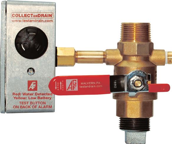
2 Model 5100A, 5200A and 5100ALBV Owner s Manual COLLECTa ndrain Anti-Trip Auxiliary Drains for Dry Pipe and Pre-Action Fire Sprinkler Systems Condensate Nipple Supply Side (Upper) Ball Valve Anti-Trip Plate Water Detection Alarm Anti-Tamper Lock Test Button (On Back Side) Model 5100A Drain Side (Lower) Ball Valve Plug Table of Contents Installation Instructions Model 5100A/5200A... 3 Model 5100ALBV Operation Instructions Model 5100A/5200A... 4 Model 5100ALBV WARNING: The COLLECTa ndrain Anti-Trip Plate is designed to make sure that the auxiliary drain is operated in the proper manner and correct sequence as per NPFA guidelines to avoid accidental tripping, improper maintenance, and acts of vandalism. The M5100ALBV Water Detection Alarm detects the presence of water in the COLLECTa ndrain and alerts personnel when maintenance is needed. COLLECTa ndrain Model 5100A and 5200A are not designed to prevent freezing or automatically drain condensation from the system. Failure to drain condensation from system may result in catastrophic system failure due to freezing. System must be maintained per NFPA , 4.6A and
3 Model 5100A/5200A Installation Instructions Retro-fitting into an Existing System 1. Isolate branch line or zone where the COLLECTanDRAIN is to be installed. 2. Relieve air pressure from the branch line. Remove existing auxiliary drain/condensation collection assembly. 4. Install the COLLECTanDRAIN by attaching the supply valve (upper) to the sprinkler system pipe in accordance with NFPA 13 (2013 edition) and with regards to low-point drains (auxiliary drains). 5. Confirm that the supply valve (upper) is in the open position and ready to collect condensation, the drain valve (lower) is closed, and the plug is tight. 6. Return system back to normal operating conditions. Installation into a New System 1. Install the COLLECTanDRAIN by attaching the supply valve (upper) to the sprinkler system pipe in accordance with NFPA 13 (2013 edition) and with regards to low-point drains (auxiliary drains). 2. Confirm that the supply valve (upper) is in the open position and ready to collect condensation, the drain valve (lower) is closed, and the plug is tight. Activate system for normal operating conditions. Note: The presence of even a small amount of water in the COLLECTa ndrain Model 5100A will activate the Model 5100ALBV Alarm s visual and audible alerts signaling the need for attention. The COLLECTa ndrain must be drained completely to silence the alarm. Please call for instructions on how to locally silence the audible alert if directly wired to a Fire Control Panel or BMS. Model 5100A/5200A Operating Instructions To Collect Condensate per NFPA 25 (2011 edition) A , * 1. Close the drain valve (lower) by making sure the valve handle is perpendicular to the collection assembly. 2. Apply Teflon tape to the plug and make sure the plug is tightly threaded into the bottom of the drain valve. Slide the Anti-Trip Plate to its lowest position. 4. Open the supply valve (upper) by making sure the valve handle is in line with the collection assembly. 5. If equipped, install the anti-tamper lock. AGF Manufacturing Inc. Phone: Fax:
4 Model 5100A, 5200A and 5100ALBV Owner s Manual To Drain Condensate per NFPA 25 (2011 edition) A , * 1. Close the supply valve (upper) and remove plug. 2. Slide the Anti-Trip Plate to its highest position and open the drain valve (lower) to drain the accumulated water. Once the water has been drained, close the drain valve (lower) and slide the Anti-Trip Plate to its lowest position. 4. Open the supply valve (upper) and allow time for any remaining water in the system to accumulate. Repeat steps 1-3 until all of the water has been drained from the system. 5. Once all water has been drained apply new Teflon tape to the plug and make sure it is tightly threaded into the bottom of the drain valve. 6. Close the drain valve (lower) and slide the Anti-Trip plate down into its lowest possible position Open the supply valve (upper). If equipped, install the anti-tamper lock. Model 5100ALBV Installation Instructions The alarm module operates on the principle of conductivity. The alarm contains a probe that is attached to the piping system. When condensate collects in the piping and reaches the probe, the electrical circuit is completed and the unit sounds an audible alarm, flashes a visual red LED, and changes the state of the output relay. The module will reset itself when the condensate is completely drained. Retro-fitting onto an Existing Auxiliary Drain 1. Isolate the auxiliary drain that the COLLECTanDRAIN Model 5100ALBV is to be installed on. 2. Remove the plug and open the drain valve (lower) to empty the condensate from the auxiliary drain and relieve the air pressure Remove the existing drain valve (lower) from the auxiliary drain. Apply PTFE tape or appropriate sealant to the Model 5100ALBV. Install the Model 5100ALBV by threading the valve into the appropriate fitting. 6. Confirm that the drain valve (lower) is closed and the plug is tight. Open the supply valve (upper) and the auxiliary drain is ready to collect condensate. 7. Return system back to normal operating conditions. 8. See Page 5-7 for Wiring Instructions. 4
. The 5100ALBV can draw up to 100mA during operation.")

 Install a 9V battery as shown in Image 2.")
5 Model 5100ALBV Operating Instructions Power is supplied to the Model 5100ALBV by a 9V Battery (default) or by installing a 12-24VDC external hard wire (See Page 6). The 5100ALBV can draw up to 100mA during operation. Ensure the power supply is sized appropriately for this and any other loads on the same circuit. Battery Operation: 1. Remove four screws on the alarm box and take off the cover. 2. For battery operation, check to make sure the Voltage Jumper is on the front two pins as shown in Image 1 (Fig. A). TEMPERATURE +V -V COM N.O. N.C. VOLTAGE Image 1 (Fig. A) Install a 9V battery as shown in Image 2. Note: When the battery begins to run low the alarm will chirp and flash a yellow LED. 4. Place 9V battery under the circuit board as shown in Image 5. Install cover with the four screws. Image 2 Image 3 AGF Manufacturing Inc. Phone: Fax:

 While supporting the bottom of the alarm enclosure, remove the knockout using a slotted screwdriver and a hammer (Place a clean rag underneath the knockout to prevent debris from falling onto the")
. Ensure DC is from a clean power supply and not fullwave rectified without a capacitor. 6. Install cover with the four screws.")
6 Model 5100A, 5200A and 5100ALBV Owner s Manual External Hardwire Operation: 1. Remove four screws on the alarm box and take off the cover. 2. For external power operation, place the Voltage Jumper on the rear two pins as shown in Image 4 (Fig. B). VOLTAGE TEMPERATURE +V -V COM N.O. N.C. Image 4 (Fig. B) While supporting the bottom of the alarm enclosure, remove the knockout using a slotted screwdriver and a hammer (Place a clean rag underneath the knockout to prevent debris from falling onto the circuit board). 4. Install ½, watertight conduit fitting or cord grip into the knockout opening and run the external power source into the alarm housing as shown in Image Connect external power source to V+ and V- terminals ash shown in Image 6 (Fig. B). Ensure DC is from a clean power supply and not fullwave rectified without a capacitor. 6. Install cover with the four screws. Image 5 Image 6 Temperature Sensing Function When the Temperature Sensing Function is enabled and water is present in the auxiliary drain the Model 5100ALBV will not activate the audible and visual alerts if the ambient temperature is above 45 F. When water is present and the ambient temperature falls below 45 F, the Model 5100ALBV will activate the audible and visual alerts. The Temperature Sensing Function helps extend battery life and eliminates unwanted alarm conditions when the threat of freezing is not present. By default the Temperature Sensing Function is enabled when shipped, meaning the alarm senses water only when the temperature is under 45 F. See page 7 to disengage Temperature Sensing Function. 6
. TEMPERATURE +V -V COM (Fig. C) N.O. N.C. Install cover with the four screws.")
: Alarm functions at < 45º F (engaged) Right/Center pins covered (Temp +): Alarm functions at all times (disengaged) The")
7 To Disengage the Temperature Sensing Function: 1. Remove four screws on the alarm box and take off the cover. 2. Remove Temperature Jumper from left/center pins and reinstall on right/center pins as shown in Image 7 (Fig. C). TEMPERATURE +V -V COM (Fig. C) N.O. N.C. Install cover with the four screws. VOLTAGE Note: If the Temperature Jumper only utilizes two pins call for instructions on how to engage/disengage the Temperature Sensing Function. Remote Notification Function NOTE: Image 7 Left/Center pins covered (Temp -): Alarm functions at < 45º F (engaged) Right/Center pins covered (Temp +): Alarm functions at all times (disengaged) The Model 5100ALBV Water Detection Alarm also features a Remote Notification Function. This function allows you to connect the unit directly to the Fire Control Panel or BSM so when water is detected in the auxiliary drain you will be notified remotely. Remote Operation Setup: 1. Remove four screws on the alarm box and take off the cover. 2. Connect wiring to the Common Terminal and either the N.O. or N.C. terminal as shown in Image 8 (Fig. D). Contact is rated for 30VDC. TEMPERATURE +V -V COM TERMINALS (Fig. D) N.O. N.C. Install cover with the four screws. VOLTAGE Image 8 Note: Please call for instructions on how to locally silence the audible alert if directly wired to a Fire Control Panel or BMS. Thank You For Using AGF Products! AGF Manufacturing Inc. Phone: Fax:

8 Auxiliary Drain Freeze Protection The Model 5400A goes beyond the prevention features of the Model 5100A and 5200A by providing a temperature controlled environment to deter system failures due to freezing condensation. The heated and insulated cabinet contains an auxiliary drain with a float switch to monitor condensation levels. When condensation reaches a level where maintenance is needed the float switch activates an audible alarm and an LED warning light. The Model 5400A also features Fire Control Panel notification capabilities. Visit for more information. AGF Manufacturing Inc. 100 Quaker Lane Malvern, PA Phone: Fax:
AGF Manufacturing Inc. Model Owner s Manual INST-5400A_V /15
 AGF Manufacturing Inc. Model 5400 INST-5400A_V003 1/15 Owner s Manual 1 AGF Manufacturing Inc. TABLE OF CONTENTS Installation Instructions... 4-7 Unpacking...4 Sprinkler System Preparation...4 Mounting...4
Exit Stopper. STI-6400 Series
 Exit Stopper STI-6400 Series Features Alarm helps prevent unauthorized exits/entries through doors. Easy to install. Select volume, alarm duration and delay settings. May be mounted on top, right, left
TECHNICAL DATA SHEET CONVENTIONAL FIRE ALARM SYSTEMS Conventional Fire Alarm Control Panel
 CVENTIAL ALARM S Features: Description: The LF-CP Series Fire Alarm Control Panel is manufactured based on advanced technology while maintaining high quality during assembly. It is of solid state circuitry
Exit Stopper. STI-6400 Series
 Exit Stopper STI-6400 Series Features Alarm helps prevent unauthorized exits/entries through doors. Easy to install. Select volume, duration and immediate or 15 second delay for arming and trip. May be
WD-CS. Water leak detection cable. Technical Overview. Features. Page 1. Data Sheet Ref: Issue: 5.1.
 Data Sheet Ref: 90501085 WD-CS Water leak detection cable Technical Overview The WD-CS range of cable sensors are typically used to detect water leaks usually under floors, and are used in conjunction
WM3000 WIRELESS MODULES
 WM3000 WIRELESS MODULES $$:05 $$:07 INSTALLATION INSTRUCTIONS Table of Contents Installation... 3 Mounting Instructions & Connections... 3 Setting the Dip Switches... 4 Setting the Recognition Time...
Addendum for STI-6406 with Dual Access Control
 Addendum for STI-6406 with Dual Access Control Description: This system contains a STI-6400 with a DPDT key switch to be mounted on one side of a door or wall; and a similar looking housing, also with
DS9370-BEL. Installation Instructions TriTech Ceiling Mount PIR/Microwave Intrusion Detector
 DS970-BEL EN Installation Instructions TriTech Ceiling Mount PIR/Microwave Intrusion Detector DS970-BEL Installation Instructions.0 Installation Considerations.0 Installation Considerations Not suitable
Installation Instructions for W2H Series Signals
 Installation Instructions for W2H Series Signals IF1513 A Description and Operation DIMENSIONS W2H A 8 7/8" (225 mm) B 8 1/4" (210 mm) C 13" (330 mm) Figure 1. Speaker/Amplifier Dimensions The W2H signaling
GRUNDFOS INSTRUCTIONS LCD 108. Installation and operating instructions
 GRUNDFOS INSTRUCTIONS LCD 08 Installation and operating instructions Installation and operating instructions Original installation and operating instructions CONTENTS Page. Symbols used in this document.
Duct and Rough Service Carbon Monoxide Sensor
 Product Identification and Overview Duct and Rough Service Carbon Monoxide Sensor BAPI s Carbon Monoxide Sensor offers enhanced electrochemical sensing with outstanding accuracy at low concentrations.
AGF Manufacturing Inc. Inspector's Test and Drain Valves for Residential and Commercial Wet Fire Sprinkler Systems
 AGF Manufacturing Inc. Inspector's Test and Drain Valves for Residential and Commercial Wet Fire Sprinkler Systems BR-TESTa ndrain_2017 1/17 Reliability, Versatility, Code Compatibility TESTa ndrain The
Low Water Cutoff (LWCO) IQ Option Card p/n , for Hot Water Boilers
 IQ Option Card p/n , for Hot Water Boilers") Low Water Cutoff (LWCO) IQ Option Card p/n 102711-01, 102714-01 for Hot Water Boilers Instruction Sheet 102-360 APPLICATION The Low Water Cutoff (LWCO) IQ Option Cards are advanced, microprocessor based
Low Water Cutoff (LWCO) IQ Option Card p/n 102711-01, 102714-01 for Hot Water Boilers Instruction Sheet 102-360 APPLICATION The Low Water Cutoff (LWCO) IQ Option Cards are advanced, microprocessor based
F PC and AO OUTPUT BOARDS INSTRUCTION MANUAL. Blue-White. Industries, Ltd.
 F-2000 PC and AO OUTPUT BOARDS INSTRUCTION MANUAL Blue-White R Industries, Ltd. 500 Business Drive Huntington Beach, CA 92649 USA Phone: 714-89-8529 FAX: 714-894-9492 E mail: sales@blue-white.com or techsupport@blue-white.com
MEGA. cal electronic gas alarm. Installation, Operation, and Maintenance Instructions. Part No Rev. D Pg.
 WARD OXYGEN Installation, Operation, and Maintenance Instructions MEGA medical electronic gas alarm MEGA WARD MEGA medical electronic gas alarm WARD POWER SUPPLY Medical Electronic Gas Alarm OXYGEN SYSTEM
LC1 & 2. Fire Alarm Panel 6\VWHPLQVWDOODWLRQRSHUDWLQJ PDLQWHQDQFH LQVWUXFWLRQV
 LC1 & 2 Fire Alarm Panel 6\VWHPLQVWDOODWLRQRSHUDWLQJ PDLQWHQDQFH LQVWUXFWLRQV ZIRCONLC1 One Zone Conventional Fire Panel ZIRCONLC2 Two Zone Conventional Fire Panel Compliant with EN54-2:1998 & EN54-4:1998
Caliber Series LED Edgelit Exit Sign EXPORT AC Only or Emergency Operation READ AND FOLLOW ALL SAFETY INSTRUCTIONS
 Caliber Series LED Edgelit Exit Sign EXPORT AC Only or Emergency Operation INSTALLATION AND OPERATING INSTRUCTIONS IMPORTANT SAFEGUARDS When using electrical equipment, basic safety precautions should
1U ULTRA Compact System
 en atel Supervisory Module SM32 Load 60 00 A IE C60947-2 G B140 4 8.2 CHNT NB1-63 C32 23 0/40 0 V e NaT el OK enatel RM 1848 enatel RM 1848 Battery 60 00A IE C60947-2 G B1 4 04 8.2 CHNT NB 1-63 C32 23
Water Leak Detector - Four Zone with open/short-circuit detection. Product overview
 Water Leak Detector - Four Zone with open/short-circuit detection Product overview The AX-WLDF is a four zone water leak detection module with open or short circuit sensor cable detection. The module must
Cautions and Warnings. Introduction 4009 NAC POWER EXTENDER
 Cautions and Warnings DO NOT INSTALL ANY SIMPLEX PRODUCT THAT APPEARS DAMAGED. Upon unpacking your Simplex product, inspect the contents of the carton for shipping damage. If damage is apparent, immediately
TOTAL SOLUTIONS. Liquid Level Control Product Guide. MATELEC AUSTRALIA innovative by design
 TOTAL SOLUTIONS Liquid Level Control Product Guide MATELEC innovative by design Liquid Level Control Contents Dual Pump Controllers Section 1 The Range Common Features Operating Data Control Logic Setup
Follett Performance Plus
 Follett Performance Plus touchscreen user guide The next level of control in undercounter refrigeration Controller Operation - Performance Plus touchscreen Use and care of the LCD Performance Plus touchscreen
Water Detection Controllers
 Page 1 of 5 Water Detection Controllers Features: Benefit: LED Status of leak status VFC output Audible alarm Auto or manual reset alarm output Uses an isolated AC signal which prevents oxidation or erosion
SECTION DIGITAL, ADDRESSABLE FIRE-ALARM SYSTEM
 SECTION 283111 - DIGITAL, ADDRESSABLE FIRE-ALARM SYSTEM PART 1 - GENERAL 1.1 RELATED DOCUMENTS A. Drawings and general provisions of the Contract, including General and Supplementary Conditions and Division
Installation Guide for AL600ULM. Multi-Output Access Control Power Supply Charger. Rev
 Installation Guide for AL600ULM Multi-Output Access Control Power Supply Charger Rev. 091800 1 AL600ULM - Multi-Output Access Control Power Supply/Charger Overview: The AL600ULM multi-output access control
Guidelines: Proper Installation of Outdoor SpectrAlert Advance Audible Visible Devices. White Paper February 2014
 Guidelines: Proper Installation of Outdoor SpectrAlert Advance Audible Visible Devices White Paper February 2014 Designed to be watertight and to operate in a wide temperature range, SpectrAlert Advance
ANSUL ANSUL AUTOMAN II-C RELEASING DEVICE
 ANSUL INSTALLATION OPERATION AND MAINTENANCE MANUAL ANSUL AUTOMAN II-C RELEASING DEVICE 001799 This manual is intended for use with the ANSUL AUTOMAN II-C Releasing Device. Those who install, inspect,
Pioneer-R16 Gas Monitor Operator s Manual
 Pioneer-R16 Gas Monitor Operator s Manual Edition 7/2/97 RKI INSTRUMENTS, INC RKI Instruments, Inc. 33248 Central Ave, Union City, CA 94587 (510) 441-5656 Chapter 1: Description About the Pioneer-R16 Gas
Single Doors FIREGUARD Series Use one Master Unit each door or one 2409 Support unit each door. Pairs of Doors
 Hinge Edge of Door Hinge Edge of Door Wiring Instructions for the Sargent 0 Series FIREGUARD Combination Door Closer-Holder and Releasing Device with Integral Smoke Detector CAUTION: FAILURE TO INSTALL
AutoTest VSR (VSR-AT) (EU) Vane Type Waterflow Alarm Switch With Electronic Retard and Auto Test Feature
 (EU) Vane Type Waterflow Alarm Switch With Electronic Retard and Auto Test Feature") AutoTest VSR (VSR-AT) (EU) Features Assembled in USA 0-30 second field replaceable electronic retard Two SPDT (Form C) switch contacts Weatherproof Easy to read wire terminal designations Easy to read
AutoTest VSR (VSR-AT) (EU) Features Assembled in USA 0-30 second field replaceable electronic retard Two SPDT (Form C) switch contacts Weatherproof Easy to read wire terminal designations Easy to read
AGF Manufacturing Inc.
 AGF Manufacturing Inc. Manual and Automatic Air Venting Valves BR-PURGEnVENT_2019 1/19 Reliability, Versatility, Code Compatibility PURGEnVENT AIR VENTING VALVES NFPA 13 (2016) standard requires the addition
Installation Guide for models:
 140 58th St. Brooklyn, NY Access Power Controllers with Power Supplies Installation Guide for models: Maximal3FD - 12VDC @ 4.6 amp or 24VDC @ 5.2 amp. - Sixteen (16) PTC protected power-limited outputs.
Wiring Instructions. Single Doors 99 Checkmate Series Use one or Master Unit each door or one or Support unit each door
 CAUTION Hinge Edge of Door Wiring Instructions Checkmate Series with Single Point Hold-Open Combination Door Closer-Holder and Releasing Device with or without Integral Smoke Detector INSTALLER: LEAVE
VIZOR Electronic Dry Pipe Accelerator (EDPA) Quick-Opening Device for Dry Pipe Systems General Description
 Quick-Opening Device for Dry Pipe Systems General Description") Worldwide Contacts www.tyco-fire.com VIZOR Electronic Dry Pipe Accelerator (EDPA) Quick-Opening Device for Dry Pipe Systems General Description The TYCO VIZOR Electronic Dry Pipe Accelerator (EDPA) is
Worldwide Contacts www.tyco-fire.com VIZOR Electronic Dry Pipe Accelerator (EDPA) Quick-Opening Device for Dry Pipe Systems General Description The TYCO VIZOR Electronic Dry Pipe Accelerator (EDPA) is
Datasheet. Dry-pipe Vacuum Sprinkler System, Electric Release Self contained unit. Features. FIREFLEX VACTEC description
 FIREFLEX VACTEC description This FIREFLEX VACTEC integrated fire protection system consists of a vacuum system trim totally pre-assembled, prewired and factory tested. All electrical and mechanical components
Installation Guide for models:
 140 58th St. Brooklyn, NY Access Power Controllers with Power Supplies Installation Guide for models: Maximal11F - Power Supply 1: 12VDC @ 3.3 amp or 24VDC @ 3.6 amp. - Power Supply 2: 12VDC @ 3.3 amp
INSTALLATION AND MAINTENANCE
 INSTALLATION AND MAINTENANCE DH100ACDCIA & DH100ACDCPA Air Duct Smoke Detector Before Installing ULC standard CAN/ULC-S524-M91 Standard For The Installation Of Fire Alarm Systems should be referenced for
LEAKMONITOR MULTIZONE WATER LEAK DETECTION ALARM PANEL INSTALLATION AND USER OPERATION MANUAL
 LEAKMONITOR MULTIZONE WATER LEAK DETECTION ALARM PANEL INSTALLATION AND USER OPERATION MANUAL The LeakMonitor alarm panel is a microprocessor controlled fully adjustable alarm system suitable for multizone
PO Box 827 Hawley, MN (218) Fax (218)
 Fax (218)") Introduction Before proceeding with the installation or operation of the Oil Alert System, read all instructions thoroughly, as well as complying with all Federal, State and Local codes, Regulations and
Introduction Before proceeding with the installation or operation of the Oil Alert System, read all instructions thoroughly, as well as complying with all Federal, State and Local codes, Regulations and
CORNELL Emergency Response Systems
 CORNELL Emergency Response Systems Door Monitor Systems Series 1000 CORNELL Communications, Inc. Milwaukee, WI USA 800-558-8957 - www.cornell.com rev 6/04 A-1000 SERIES DOOR MONITOR OPERATION AND WIRING
TraceTek Sensing Module Installation, Operation and Maintenance Instructions DESCRIPTION SPECIFICATIONS APPROVALS TYPE NM
 TTC-1 TraceTek Sensing Module Installation, Operation and Maintenance Instructions DESCRIPTION The nvent RAYCHEM TraceTek TTC-1 sensing module is used with TraceTek sensing cables to detect liquid leaks.
Operation 8085C ENGLISH. Customer Support: or Visit our webiste Printed in China
 Operation 8085C MENU PROGRAM RESET ENGLISH MENU PROGRAM RESET Customer Support: 888-515-2585 or Visit our webiste www.ritetemp-thermostats.com Printed in China 1-402-006 Operation 8085C PG 1 Day Indoor
Pre-March 2016 Design - Click to be redirected to newer SBS-H2 design SBS-H2. Hydrogen Gas Detector Kit
 Pre-March 2016 Design - Click to be redirected to newer SBS-H2 design N56 W16665 Ridgewood Drive Menomonee Falls, WI 53051 SBS-H2 Hydrogen Gas Detector Kit For battery charging rooms and other areas where
STEAMPRO. Steam Generator Troubleshooting and Service Guide
 STEAMPRO Steam Generator Troubleshooting and Service Guide TABLE OF CONTENTS Page PREFACE... 1 I. STEAMPRO STEAM GENERATOR SYSTEM...2 II. PLUMBING AND ELECTRICAL...3-4 III. SYSTEM OVERVIEW... 5-10 IV.
Sentry LIQUID LEVEL ALARM MODEL 100 OPERATING MANUAL.
 Sentry LIQUID LEVEL ALARM MODEL 100 OPERATING MANUAL www.aquaticsentry.com TABLE OF CONTENTS 1. SAFETY PRECAUTIONS... 3 2. APPLICATION... 3 2.1 HIGH Liquid Level Alarm 2.2 LOW Liquid Level Alarm 3. INSTALLATION...
Booster Power Supply Manual
 Supply Manual DEVELOPED BY COPYRIGHT NOTICE General Signal Building Systems Corporation 6411 Parkland Drive Sarasota, FL 34243 (941) 739-4300 Copyright 1999 General Signal Building Systems Corporation
Addressable Detectors & Bases
 Edwards Signaling Catalog u Intelligent Initiating Addressable Detectors & Bases Detectors: E-PD, E-PHD, E-HD Bases: B4U, RB4U, IB4U, SB4U Overview Edwards intelligent addressable detectors are meticulously
21-light Remote Annunciator. Owner s Manual
 21-light Remote Annunciator Owner s Manual Annunciator Description... Inside Font Cover Detailed Specifications... 1 Environmental Specifications... 1 Power Supply Requirements... 1 Communication With
Model PAD-3 Distributed Power Module NAC Expander Installation, Operation, and Maintenance Manual
 Fire Safety Model PAD-3 Distributed Power Module NAC Expander Installation, Operation, and Maintenance Manual Siemens Building Technologies, Inc. Siemens Building Technologies, Ltd. 8 Fernwood Road 2 Kenview
TECHNICAL DATA. Humidity: 85% Relative Humidity (non-condensing) at 90 F (32 C) maximum.
 at 90 F (32 C) maximum.") September 29, 1997 Firecycle III 433 a 1. PRODUCT NAME VIKING Model E-1 Manufactured 1997 Present 2. MANUFACTURED FOR THE VIKING CORPORATION 210 N Industrial Park Road Hastings, Michigan 49058, U.S.A.
September 29, 1997 Firecycle III 433 a 1. PRODUCT NAME VIKING Model E-1 Manufactured 1997 Present 2. MANUFACTURED FOR THE VIKING CORPORATION 210 N Industrial Park Road Hastings, Michigan 49058, U.S.A.
SMART EVO 2 - User Manual ELECTRICAL PANEL FOR 2 MOTORS
 SMART EVO 2 - User Manual ELECTRICAL PANEL FOR 2 MOTORS CONTENTS 1. INTRODUCTION... 5 2. WARNINGS... 6 3. GENERAL DESCRIPTION... 7 4. INSTALLATION... 8 5. LUMINOUS INDICATORS AND COMMANDS... 9 6. DIP-SWITCH
Functional Performance Test
 Fire Alarm Control Panel & Fire Alarm Annunciator Panel Notify all building occupants that testing will be conducted. Fire alarm contractor shall have personnel with 2-way radios at the fire alarm control
Pump-Up Controller MODEL 4062
 Pump-Up Controller 4-20mA Input/Scalable Output Seal Fail Monitoring Duplex Pump Alternation Hand-Off-Auto Controls Dual Run-time Meters RS-485/Modbus Communications DESCRIPTION The Model 4062 Pump-Up
USER GUIDE. Paperless Humidity/Temperature Chart Recorder. Model RH520A 21.2 C 13:
 USER GUIDE Paperless Humidity/Temperature Chart Recorder Model RH520A 30 10 100 0 13:45 04-23-04 21.2 C 38 Introduction Congratulations on your purchase of the Extech RH520A Temperature + Humidity Chart
Installation Instructions
 CRSMKKIT002A00 CRSMKSEN002A00 FIELDINSTALLEDSMOKEDETECTORS FOR MEDIUM ROOFTOP UNITS 15 to 25 TONS Installation Instructions TABLE OF CONTENTS PACKAGE CONTENTS... 1 SAFETY CONSIDERATIONS... 1 GENERAL...
Smart Temp. ApolloP/n Installation Manual. Version 1.0
 Smart Temp ApolloP/n 44-800 Installation Manual Version 1.0 TABLE OF CONTENTS Introduction...6 Getting started...7 Installing the thermostat...8 Disassembly...8 Thermostat location...8 Mounting the subbase...8,
GAS SUPRESSION CONTROL PANEL:
 GAS SUPRESSION CONTROL PANEL: MODEL NAME: COMPANY: DELTA 437/2, Main Road, Mandwali Fazalpur, Delhi-110092 Page 1 ABOUT THE PRODUCT ASES is very proud of to introduce DELTA the completely digital microprocessor
Electro-Sentry. Users Manual
 Electro-Sentry Users Manual 2. To view an individual point, e.g. Speed just touch that point and it will display a graph showing the 45 min. of activity. Viewing a Leg: 1. Touch the desired leg, e.g. East
SERVICE MANUAL FOR 6537 & 6538 SERIES TWO TON HIGH EFFICIENCY PACKAGED HEAT PUMPS
 SERVICE MANUAL FOR 6537 & 6538 SERIES TWO TON HIGH EFFICIENCY PACKAGED HEAT PUMPS TABLE OF CONTENTS 1. Warnings.................................................................. 2 2. Accessibility Of Appliance....................................................
Analog Room Pressure Monitor RPC Series
 Description The Room Pressure Monitor is used to measure differential pressure in the range of 0.125 to 1"wc or 30 to 250 Pa. It combines precision high sensitivity silicon sensing capabilities and the
IMPORTANT SAFEGUARDS READ AND FOLLOW ALL SAFETY INSTRUCTIONS. HZM-Series-Class I, Div 2 Battery Unit. Instalation instructions
 HZM-Series-Class I, Div 2 Battery Unit HZM-Series-Class I, Div 2 Battery Unit Instalation instructions IMPORTANT SAFEGUARDS 1 4 5 6 7 13 When using electrical equipment, basic safety precautions should
EVO192 v3.0 Fire and Burglary What s New
 EVO192 v3.0 Fire and Burglary What s New Compatibility: EVO192 v3.0 TM50 v1.31 K641 v2.41 Overview: CP-01 Compliancy Wiring Diagram The following sections/options have been added to the EVO192 panel. They
Installation Manual CFP-105. Fire Alarm Control Panel. Version 1.0
 CFP-105 Fire Alarm Control Panel Installation Manual Version 1.0 WARNING: This manual contains information on limitations regarding product use and function and information on the limitations as to liability
System 800 Addressable Fire Detection & Alarm System
 SECTION 5: page 1 Section 5: System 800 Addressable Fire Detection & Alarm System SECTION 5: page 3 10 reasons to specify 800 1 Plug and Play A user friendly panel not requiring special software tools
Pump-Down Controller MODEL 4052
 Pump-Down Controller 4-20mA Input/Scalable Output Seal Fail Monitoring Duplex Pump Alternation Hand-Off-Auto Controls Dual Run-time Meters RS-485/Modbus Communications DESCRIPTION The Model 4052 Pump-Down
Freeze Protection Thermostat TRACON MODEL GPT 3 Installation and Operation Manual
 MANUAL We manage heat Freeze Protection Thermostat TRACON MODEL GPT 3 Installation and Operation Manual Environmental Technology, Inc. 1850 N Sheridan Street South Bend, Indiana 46628 http://www.networketi.com/
STA16 SELECTRONIC ALARM ANNUNCIATORS DESIGN, INSTALLATION AND OPERATING MANUAL STA16
 ST-97106N Revised 07-04 Section 25 (00-02-0283) STA16 SELECTRONIC ALARM ANNUNCIATORS DESIGN, INSTALLATION AND OPERATING MANUAL STA16 Certain danger to human safety and to equipment may occur if some equipment
LMS-188-4P-BMS 4 POINT DIGITAL MONITOR/ALARM WITH PROTOCOL CONVERTER OPERATING INSTRUCTIONS
 G LMS 188 4P BMS August, 2018 LMS-188-4P-BMS 4 POINT DIGITAL MONITOR/ALARM WITH PROTOCOL CONVERTER OPERATING INSTRUCTIONS! WARNING: This product can expose you to chemicals including lead, which is known
Installation Instructions
 ELCU-200 Control Unit Circle CUT-OUT R8.5 mm Push to Test Specifications Cir.# Remote Activation Voltages... 120/277VAC 50/60Hz Max Load Requirements Ballast... 20A @120/277VAC Incandescent... 10A @120VAC
5U Compact System. Installation Manual V1.0. Manufactured by Enatel Ltd. 321 Tuam Street PO Box Christchurch New Zealand
 5U Compact System Installation Manual V1.0 Manufactured by Enatel Ltd. 321 Tuam Street PO Box 22-333 Christchurch New Zealand Phone +64-3-366-4550 Fax +64-3-366-0884 Email sales@enatel.net www.enatel.net
Remote Chexit Module (RCM) System. General Information
 System. General Information") *911032-00* 911032-00 Wiring and Configuration Remote Chexit Module (RCM) System Installation Instructions General Information The Von Duprin RCM is designed for controlled egress applications. It meets
*911032-00* 911032-00 Wiring and Configuration Remote Chexit Module (RCM) System Installation Instructions General Information The Von Duprin RCM is designed for controlled egress applications. It meets
WIRING DIAGRAM AND INSTRUCTIONS
 DGPROX PIN Code and/or Badge STAND-ALONE PROXIMITY SYSTEM Wiring diagram PCB front view 8 WIRING DIAGRAM AND INSTRUCTIONS ST2 1 3 1 3 Warning Do not use a switching power supply because of the interference
SAFETY INFORMATION AND WARNINGS
 This manual refers to the Model SST-3 control panel manufactured since October 31, 2013, which uses a universal (100 277 VAC; 50/60 Hz) power supply. Older units use a voltage-specific power supply and
AL802ULADA. NAC Power Extender. Installation Guide. (See Application Guide for additional information) Rev
 Rev") AL802ULADA NAC Power Extender Installation Guide (See Application Guide for additional information) Rev. 031703 Overview: The Altronix AL802ULADA is an extremely cost effective 8 amp voltage regulated
AL802ULADA NAC Power Extender Installation Guide (See Application Guide for additional information) Rev. 031703 Overview: The Altronix AL802ULADA is an extremely cost effective 8 amp voltage regulated
PS6 SERIES. Installation PS6 SERIES. Power Supplies c/w Fire Panel Interface, EOL Trigger and Standby Power Option
 Installation PS6 SERIES Power Supplies PS6 SERIES Power Supplies c/w Fire Panel Interface, EOL Trigger and Standby Power Option Installation and Specifications Manual ISDPS6_SERIES 08121590 PCN15016 R05/15GR
PRX-320 Waterproof Proximity Access Operating Instructions and Installation Manual
 PRX-320 Waterproof Proximity Access Operating Instructions and Installation Manual Contents I. SPECIAL FEATURES 1 II. FRONT PANEL 1 III. INSTALLATION PROCEDURES AND PROXIMITY CARD TYPES 2 IV. SETTING
AquiTron. AT-LDM Liquid Detection Module INSTALLATION INSTRUCTIONS
 AquiTron Liquid Detection Module INSTALLATION INSTRUCTIONS Please read these instructions carefully and keep them in a safe place (preferably close to the module) for future reference. These instructions
Wiring Instructions (01-09)
") CAUTION Wiring Instructions 0--00-0 (0-0) Power Track Series with Single Point Hold-Open Electromechanical Releasing Device with Multi-Point Hold- Open TO PREVENT ELECTRICAL SHOCK AND EQUIPMENT DAMAGE,
CAUTION Wiring Instructions 0--00-0 (0-0) Power Track Series with Single Point Hold-Open Electromechanical Releasing Device with Multi-Point Hold- Open TO PREVENT ELECTRICAL SHOCK AND EQUIPMENT DAMAGE,
MAINTENANCE & TROUBLESHOOTING GUIDE LEAK ALARM CHANNEL DRY OIL WATER AUX ALARM HIGH LOW CRITICAL WATER TANK LEVEL ALARM MODEL LDE-740 ADVANCE PAPER
 PNEUMERCATOR Liquid Level Control Systems Electronic Systems Excluding LC2000 And TMS Series MAINTENANCE & TROUBLESHOOTING GUIDE 400 300 500 FUEL LEVEL LEAK MONITOR 1 200 600 OIL/GAS NORMAL WATER PNEUMERCATOR
IMPORTANT SAFEGUARDS READ AND FOLLOW ALL SAFETY INSTRUCTIONS. 3LERHZ Series Class I, Div 2 Combo Unit. Installation instructions
 3LERHZ Series Class I, Div 2 Combo Unit Installation instructions 3LERHZ Series Class I, Div 2 Combo Unit IMPORTANT SAFEGUARDS 1 3 When using electrical equipment, basic safety precautions should always
MS-4012/4024 and CMS-4012/4024. Instruction Manual for the. Fire Alarm Control Panels
 R 12 Clintonville Road, Northford, CT 06472 Phone: (203) 484-7161 FAX: (203) 484-7118 Instruction Manual for the MS-4012/4024 and CMS-4012/4024 Fire Alarm Control Panels Document 15586 5/11/93 Revision:
Installation Guide for AL800UL-ADA. NAC Power Extender. Rev
 Installation Guide for AL800UL-ADA NAC Power Extender Rev. 090500 Overview: The Altronix AL800UL-ADA is an extremely cost effective 8 amps voltage regulated remote power supply /battery charger. The AL800UL-ADA
DS3MX-E-I. Installation Guide. 3 Zone Mini Control Panel
 DS3MX-E-I EN Installation Guide 3 Mini Control Panel DS3MX-E-I Installation Guide 1.0 General Information EN 2 1.0 General Information The DS3MX is a three zone mini control panel, which can be installed
DE5300 Delayed Egress System. General Information
 *911031-00* 911031-00 Wiring and Configuration DE5300 Delayed Egress System Installation Instructions General Information The Von Duprin DE5300 is designed for controlled egress applications when used
aquilar - leak detection solutions
 AT-MZA Multi Zone Alarm OPERATI & MAINTENANCE MANUAL AT-MZA Multi Zone Alarm OPERATI & MAINTENANCE MANUAL Product Information MZA 115Vac +15%, -20%; 50/60 Hz 230Vac ±10%; 50/60 Hz 12Vdc ±20% Power consumption
Wiring Instructions for the 2900 Series FIREGUARD Combination Door Closer-Holder and Releasing Device with Integral Smoke Detector
 Wiring Instructions for the 900 Series FIREGUARD Combination Door Closer-Holder and Releasing Device with Integral Smoke Detector CAUTION: FAILURE TO INSTALL OR ADJUST PROPERLY MAY RESULT IN INJURY OR
Water Leak Detector. Installation and Troubleshooting. Overview
 Overview Water Leak Detector The Water Leak Detector is designed to sense the presence of water and alert a central monitoring system of the potentially destructive situation. Upon water detection, an
IMPORTANT SAFEGUARDS READ AND FOLLOW ALL SAFETY INSTRUCTIONS SAVE THESE INSTRUCTIONS. NXM Series - Survive-All. Emergency Light Unit
 Emergency Light Unit IMPORTANT SAFEGUARDS When using electrical equipment, basic safety precautions should always be followed including the following: READ AND FOLLOW ALL SAFETY INSTRUCTIONS 1. Do not
Fire Control/Communicator
 Operation and Installation Manual Fire Control/Communicator 1 2 3 4 5 12V AC,20V A, 60Hz or +24V DC 12V AC, 20V A, 60Hz or -24V DC EARTH GND BATTERY - BATTERY + 6 INITIATING A1-7 INITIATING A2-8 INITIATING
RAPID RESPONSE Model RCP-1 Residential Control Panel 1 or 1-1/2 Inch (DN25 or DN40), 175 psi (12,1 bar) General Description.
, 175 psi (12,1 bar) General Description.") Worldwide Contacts www.tyco-fire.com RAPID RESPONSE Model RCP-1 Residential Control Panel 1 or 1-1/2 Inch (DN25 or DN40), 175 psi (12,1 bar) General Description The TYCO RAPID RESPONSE Model RCP-1 Residential
Worldwide Contacts www.tyco-fire.com RAPID RESPONSE Model RCP-1 Residential Control Panel 1 or 1-1/2 Inch (DN25 or DN40), 175 psi (12,1 bar) General Description The TYCO RAPID RESPONSE Model RCP-1 Residential
MASTER JOCKEY PUMP CONTROLLER. Model JPCE INSTRUCTION MANUAL. C 2018 Master Control Systems, Inc
 MASTER JOCKEY PUMP CONTROLLER Model JPCE INSTRUCTION MANUAL C 2018 Master Control Systems, Inc TABLE OF CONTENTS Important Safety Information. Page 3 General Description and Installation.. Page 4 Model
Operating & Maintenance Manual. Alert-4 Ethernet LCD Master Alarm
 Operating & Maintenance Manual Alert-4 Ethernet LCD Master Alarm w w w. a m i c o. c o m Contents User Responsibility 4 Introduction 4 Features 5 Description of the Alarm 5 Shipment Details 5 The Alarm
Series. Access Power Controllers. Installation Guide
 Series Access Power Controllers Installation Guide Models Include: Maxim11 - Power Supply 1: 12VDC @ 3.5 amp or 24VDC @ 2.7 amp. - Power Supply 2: 12VDC @ 3.5 amp or 24VDC @ 2.7 amp. - Sixteen (16) fuse
Specification/ Data Sheet
 Specification/ Data Sheet TRITON RP Agent Release Control Panel FEATURES Agent Release Control Panel designed specifically for suppression release operation with: Four initiating device circuits (IDCs)
D-Tect 2 GJD300 Quad PIR Movement Detector
 D-Tect GJD0 Quad PIR Movement Detector Package Contents 3. Package Contains: x D-Tect x Drilling template for fixing holes x Allen Key 3 x 3.75mm wall plugs 3 x 3.75mm screws x Spare Sliding Curtains x
Annunciators, 8 LED. D7030X, D7030X-S2, and D7030X-S8. Installation Manual
 Annunciators, 8 LED D7030X, D7030X-S2, and D7030X-S8 en Installation Manual Annunciators, 8 LED Notices en 3 1 Notices These instructions cover the installation of the D703X, D7030X-S2, and D7030X-S8
TrueAlert Multi-Candela Notification Appliances
 UL, ULC Approved* TrueAlert Multi-Candela Notification Appliances Non-Addressable Visible Only Amber Lens Strobes for Emergency Communications Features Visible only (V/O) 24 VDC wall mount notification
The TC-4F. Time Control Module C P/N 15972:C ECN For the Sensican 2000 Fire Alarm Control Panel
 12 Clintonville Road Northford, CT. 06472 (203) 484-7161 FAX:(203) 484-7118 The TC-4F Time Control Module For the Sensican 2000 Fire Alarm Control Panel Document # 15972 3/27/95 Revision C P/N 15972:C
3MAVR60XX Series Fan. Owner s Guide and Installation Manual. UL Model NO. : 3MAVR60XX
 Owner s Guide and Installation Manual 3MAVR60XX Series Fan UL Model NO. : 3MAVR60XX Attach sales receipt to this card and retain as your proof of purchase DATE OF PURCHASE: MODEL NUMBER: RETAILER NAME:
Notification Appliance Circuit Module
 Notification Appliance Circuit Module D192G en Installation guide Notification Appliance Circuit Module Notices en 3 1 Notices These instructions cover the installation of the D192G Notification Appliance