METAL FILE CABINET METAL FILE CABINET
|
|
|
- Noah Gaines
- 5 years ago
- Views:
Transcription
1 DFDF DDD FFF DFDF DFDF DDD FFF DFDF
2
3
4 S METAL FILE CABINET METAL FILE CABINET
5 EMPLOYEES ONLY EMPLOYEES ONLY
6 7'-6 1/2"
7 ALL-GENDER RESTROOM TYP EXIT EXIT FIRE E X T I N G U I S H E R CAUTION Do not block door FIRE E X T I N G U I S H E R CAUTION Do not block door EMERGENCY EXIT ONLY ALARM WILL SOUND EMERGENCY EXIT ONLY ALARM WILL SOUND LADDER MUST BE CHAINED WHEN NOT IN USE EMPLOYEES ONLY EMPLOYEES ONLY FIRE E X T I N G U I S H E R
8
9
10 #
11
12
13
14
15
16
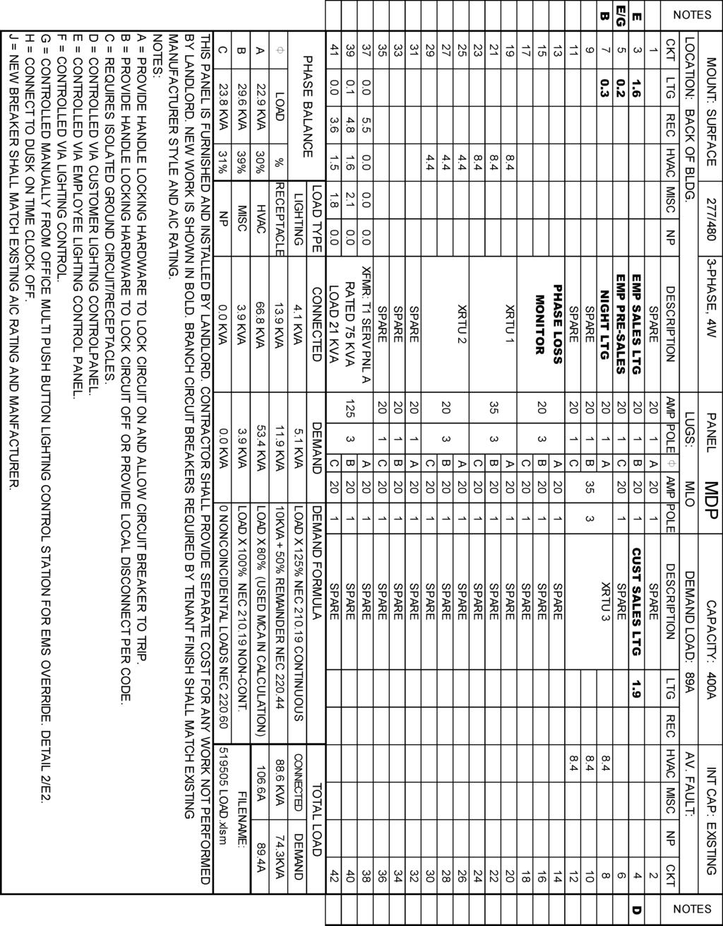
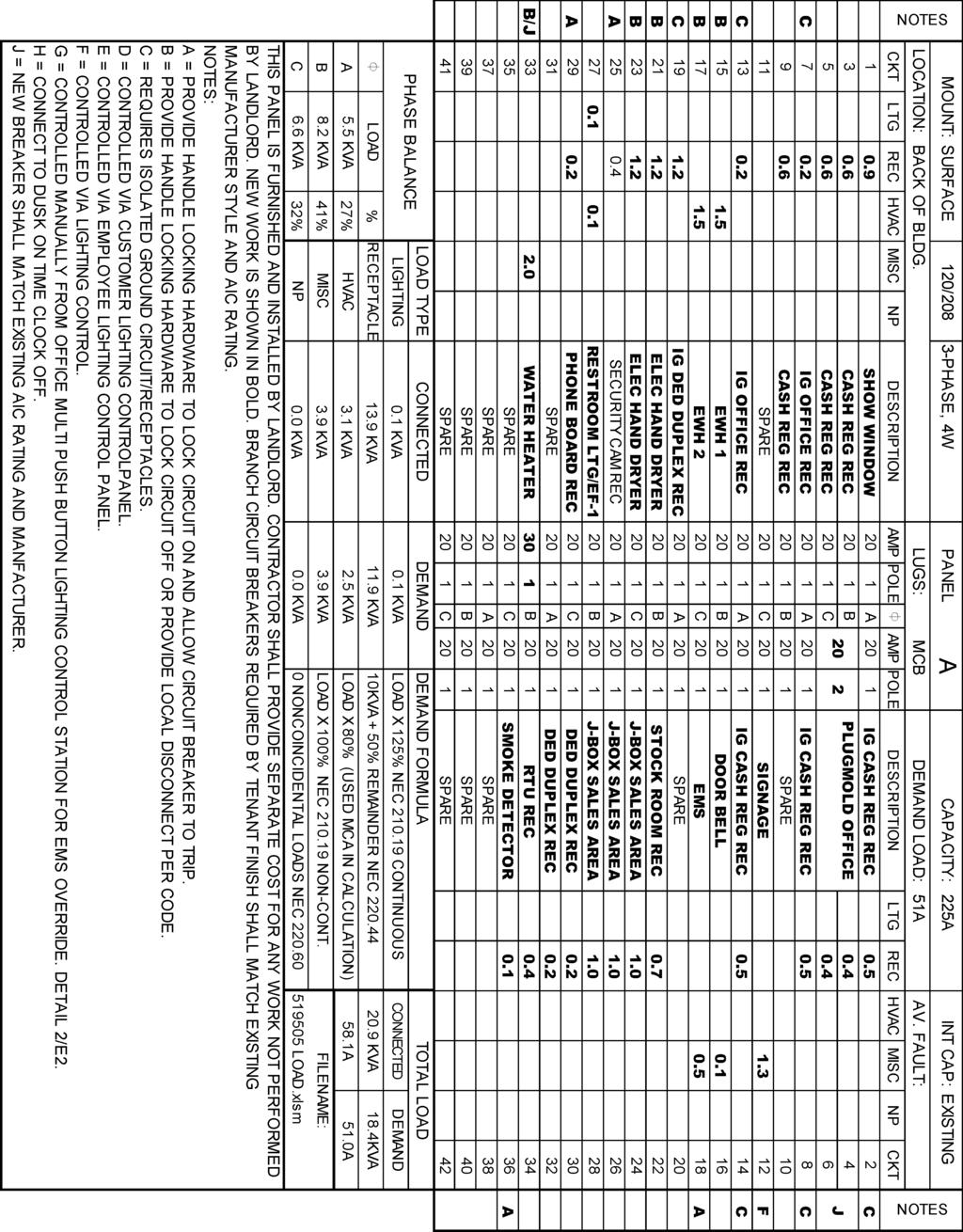
17 COM 3 COM 4 POWER FAULT I/O STATUS COM 5 COM 6 COM 7 COM 8 CLASS 2 OUTPUT 4 CLASS 2 OUTPUT 1 LAN 2 LAN 1 STATUS BEAT UPDATED 06/29/ Novar - ENERGY MANAGEMENT SYSTEM (EMS): Installation Scope of Work I. GENERAL CONTRACTOR'S RESPONSIBILITIES: a. Read Dollar Tree Documentation Package (this document) and distribute to mechanical and electrical contractors. b. Arrange for the electrical and mechanical contractors to be present during the entire remote commissioning for a two-hour period, via telephone, for a complete commissioning of the EMS as deemed by Novar Systems Commissioning Agent. c. Remote EMS commissioning shall be scheduled 24 hours prior to requested commissioning date. Contact Novar Programming: i. Ops.Checkout@novar.com d. Confirm that the mechanical and electrical contractors have completed the Novar Survey form. FAX Survey form (pages 1 and 2 above): i. Dollar Tree Survey Form Fax: e. For Project Support (non-programming issues), contact Novar Project Manager: i. Richard Doncaster, Novar PM: ; richard.doncaster@novar.com f. If contacts above cannot be reached, please call Novar at: i. Novar General Number: II. ELECTRICAL CONTRACTOR'S RESPONSIBILITIES: a. Provide labor and installation material, as required, for a complete and operational Novar EMS for this Dollar Tree Stores location. b. Receive and store all Novar material in a safe and secure place until the EMS installation has been completed. c. The following equipment will be supplied by Novar, and installed by the Electrical Contractor: i. 1 Outdoor Light and Temperature Sensor Assembly (OSA) ii. 1 Integrated Controller/ Contactor Panel (RCP Panel) iii. 1 Manager Timed Override Panel or Remote LCD iv. 1 Seven Foot Ethernet Patch Cable (CAT5) d. Review the entire set of site plans, perform a job site survey and inventory the Novar equipment to ensure the proper equipment has been ordered and received for a complete and operational Novar EMS. e. If any material is missing or additional equipment (e.g. lighting contactors) required, immediately call Novar PM to request an order. f. Electrical Contractor shall verify number of rooftop units and number of controlled lighting circuits against the design and report discrepancies that cannot be resolved in the field, to the Novar Project Manager. g. All EMS cables are to be installed per National and Local codes. It is the Electrical Contractor's responsibility to determine if national and local codes permit class 2 cables to be installed exposed within the building structure or if a full conduit system is required. h. EMT connectors and bushings are to be installed at the top of every conduit sleeve to protect EMS cables from abrasions. All cables are to be clearly and distinctly labeled at both ends. i. Perform all work in accordance with all national, state, or local codes for this project. j. Coordinate the EMS installation with the Mechanical Contractor to avoid any interference that may delay progress during construction. k. Furnish and install all required conduit, boxes, wire ways, fittings, straps, hangers and wiring for a complete and operational EMS as required. l. Coordinate with the Mechanical Contractor for locations when running communication and sensor wires. m. Contractor shall install an Ethernet cable run from the Integrated controller/contactor panel to the (HUB) under Cash Register #1.Contractor will terminate both ends of the cable, test cable for proper wiring, plug one end of the Ethernet cable into the (HUB) and terminate the other end of the Ethernet Cable into the NOVAR XCM20R executive controller LAN1 (PRI) RJ-45 jack. n. Furnish and install a dedicated 120 VAC circuit for the RCP Panel. i. Label: DO NOT TURN OFF / RCP EMS ii. Confirm wiring is completed as per Documentation Package before applying power. Improper wiring will cause damage to equipment. o. Furnish and install a 3-pole, 20 amp breaker/disconnect at the main distribution panel (MDP) for phase loss monitor power. i. Label: DO NOT TURN OFF / PHASE FAILURE ii. Confirm wiring is completed as per Documentation Package before applying power. Improper wiring will cause damage to equipment. p. Mount the Remote Override Panel (ROP) or Remote LCD in Manager's Office Area, see EMS drawings for details. q. Connect the Ethernet patch cord provided from the XCM20R Controller to the RJ-45 Ethernet jack. If the Ethernet jack is not yet in place, connect one end of the patch cord to the XCM20R System Controller, coil and tape the other end of the cord to the conduit for future connection. r. Mount the integrated controller/contactor panel adjacent to the electrical panels. Install the lighting circuit home runs from the fixtures straight to the load side of the contactors. Install the circuits from the line side of the contactors to each breaker as follows: III. NOVAR RESPONSIBILITIES: a. If any end unit (e.g. lighting, roof top unit, supply air fan) cannot be operated for mechanical or electrical reasons, Novar will verify the proper operation of the control devices (e.g. contactors, discrete I/O) leading up to the unit. b. Timed operation of lighting loads - employee, customer, exterior signage, and security. c. Outside light level control of lighting loads - exterior signage and security. d. Operation of HVAC unit heating stages, as indoor environment allows. e. Operation of HVAC cooling stages, as indoor and outdoor environments allow. f. Verification of HVAC unit sensor readings - space and supply temperatures. g. Timed override operation of lighting loads. h. Operation of phase loss monitor HVAC load lockout. i. CO2 level on Sales Floor j. The following services will be supplied by Novar : i. Equipment shipping to the job ii. Pre-programming and downloading of Novar equipment. iii. Telephone technical support at (216) iv. Remote system checkout with installing contractor IV. MECHANICAL CONTRACTOR'S RESPONSIBILITIES: a. Provide labor and installation material, as required, for a complete and operational Novar EMS for this Dollar Tree Stores tenant space. b. Mechanical Contractor shall verify number and type of roof top units against the design and report discrepancies that cannot be resolved in the field to the Novar Project (216) for further instruction. c. The following equipment will be supplied by Novar and installed by the Mechanical Contractor: i. Remote Duct Temperature Sensors (As Required) ii. Remote Space Temperature Sensors (As Required) i. Please refer to Down Rod installation instructions for correct placement of Remote Space Temperature Sensors. iii. 1 CO2 Sensor d. Amended stores only, provide credit back to Dollar Tree Stores Inc. for any equipment and/or labor that has been omitted from the original bid as a result of the EMS installation, i.e.; contactors, relays, thermostats, etc. e. Perform all work in accordance with all national, state, or local codes for this project. Coordinate the EMS installation with Electrical Contractor to avoid any interference that may delay progress during construction. f. Install 18/9 cable (MC Supplied) between the UCM controller and rooftop unit. Terminate R, G, Y1, Y2, W1, and W2 for control of fan, cooling and heating. Secure the communications cables to the UCM Controller as shown. Provide 24VAC power to the UCM controller from the roof top unit transformer. Power to the controller must be off while terminations are made. g. Mount the remote supply duct temperature sensor of each roof top unit. The remote supply duct temperature sensor should be mounted no closer than six feet from the roof top unit penetration measured along the duct. Install and secure the supply duct temperature sensor wire (18/2 Shielded, MC Supplied) to the UCM Controller location and terminate, as shown. h. Provide a technician for an approximate 2-hour remote telephone checkout with Novar. i. If extra equipment exists after installation (e.g. sensors), inform the Novar personnel at checkout to arrange for RMA # to return the material j. Coordinate with the Electrical Contractor to verify proper HVAC control during the Novar remote telephone checkout. Provide Electrical Contractor with roof plan layout, showing location of RTUs on the roof. k. Mount the CO2 sensor per Dollar Tree Stores location criteria, i.e. one sensor in Sales Floor area. Install and terminate sensor's signal wires and power wires as shown on EM-2. DO NOT CALIBRATE CO2 SENSOR! FIELD CALIBRATION WILL CAUSE SENSOR FAILURE. l. Install and terminate DCV wires to economizer section of RTUs as shown on EM-3. If RTUs do not have economizer section, DCV wires do not need to be installed, but CO2 sensor should still be installed in space. m. Set address and configuration DIP switches on the UCM Controller, as shown on the face of the controller. Lighting load RCP Contactor(s) Where ckts identified on DT construction dwgs Employee C1A/C1B Electrical Panel Schedule (E3) Customer C2A/C2B Electrical Panel Schedule (E3) Exterior/Signs C3 Electrical Panel Schedule (E3) Pre Sales C4 (As Required) Electrical Panel Schedule (E3) Lighting load LHP Contactor(s) Where ckts identified on DT construction dwgs Light Harvesting C1 (As Required) Lighting Plan (E2) T3 T3 T3 T3 s. Mount the Outdoor Sensor Assembly (OSA) on the roof top unit that resides closest to the XCM20R System Controller. Mount the device on a 1" rigid riser and 'LB' to back of Assembly, 3 feet above the roof top unit, facing north, away from the combustion heat blower and condenser fan. n. When applicable, install indoor light sensor as directed per EM-4. o. Amended stores only, provide credit back to Dollar Tree Stores Inc. for any equipment that has been omitted from the original bid as a result of the EMS installation, i.e.; time clocks, contactors, switches, etc. p. Upon completion of the installation, the Electrical Contractor will fill in the information below, coordinate with Mechanical Contractor to be present and contact Novar to schedule a remote checkout at Ops.Checkout@novar.com. If both Electrical Contractor and Mechanical Contractor are not present, the checkout can not be scheduled. q. Provide a technician for an approximate 2-hour remote telephone checkout with Novar r. Coordinate with the Mechanical Contractor to verify HVAC control during the Novar remote telephone checkout. s. If extra equipment exists after installation, the Electrical Contractor will inform Novar personnel at checkout to arrange for RMA # to return the material Rockside Woods Blvd. Cleveland, OH ENERGY MANAGEMENT SYSTEM SINGLE LINE DIAGRAM. POWER AC FAULT CLASS 2 OUTPUT 3 CLASS 2 OUTPUT 2 RS-232 COM 1 R 4 R 3 R 2 R EMS REMOTE TESTING CHECKLIST PERMANENT POWER APPLIED TO BUILDING. ALL INTERIOR LIGHTING AND LIGHTING CONTACTORS WIRED AND OPERATIONAL. 120 VAC CONTROL CIRCUIT INSTALLED AND WIRED TO EMS-IFP. 240/480 VAC 3 PHASE CIRCUIT INSTALLED AND WIRED TO EMS PHASE LOSS RELAY. ALL EMS CABLE AND WIRING INSTALLED AND TERMINATED AS PER THE DRAWINGS AND MANUFACTURERS INSTRUCTIONS. ALL EMS COMPONENTS INSTALLED AND OPERATIONAL AS PER DRAWINGS AND MANUFACTURER'S INSTRUCTIONS. NATURAL GAS UTILITY SERVICE APPLIED TO BUILDING (IF APPLICABLE). HIGH-SPEED INTERNET/INTRANET SERVICE APPLIED TO BUILDING. RJ-45 ETHERNET CABLING INSTALLED AND OPERATIONAL FOR REMOTE COMMUNICATIONS. ALL HVAC COMPLETE AND OPERATIONAL. ELECTRICAL CONTRACTOR HAS QUALIFIED TECHNICIAN SCHEDULED FOR REMOTE SYSTEM TESTING. MECHANICAL CONTRACTOR HAS QUALIFIED TECHNICIAN SCHEDULED FOR REMOTE SYSTEM TESTING. Energy Management Plan R. James CR GN 11/13/2014 U- Single Line Diagram N.T.S. EM-1
18 UPDATED 06/29/16 RS-232 COM 1 COM 3 COM 4 COM 5 COM 6 COM 7 COM R R R LAN 2 LAN 1 STATUS BEAT 5 1 R POWER AC FAULT POWER FAULT I/O STATUS CLASS 2 OUTPUT 4 CLASS 2 OUTPUT 3 CLASS 2 OUTPUT 2 CLASS 2 OUTPUT 1 NORM SHELL MODE JUMPER CONFIG. SHELL POWER RATINGS: 24 VAC, 40 VA CLASS 2 SERIAL # LAN 2 (SEC) LAN 1 (PRI) USB R RCP PANEL - NOVAR OPUS XCM20R WIRING DIAGRAM 6060 Rockside Woods Blvd. Cleveland, OH Energy Management Plan WARNING: DEVICE POWER IS POLARITY SENSITIVE. REVERSING POLARITY WILL DAMAGE DEVICE NOTE: INSTALL CO2 SENSOR AT 7' AFF ON COLUMN IN THE SALES AREA TO CONTROL THE SALES AREA RTU'S. OSA - OUTDOOR SENSOR ASSEMBLY CO2 SENSOR OVERRIDE #1: EMPLOYEE LIGHTS OVERRIDE #2: EXTERIOR LIGHTS OVERRIDE #3: PRE-SALES LIGHTS (AS REQUIRED) OVERRIDE #4: LIGHT HARVEST (AS REQUIRED) INSTALLATION NOTES: 1) OVERRIDE PANEL NOT REQUIRED ON SITES WITH REMOTE LCD DISPLAYS. 2) PRE-SALES OVERRIDE NOT REQUIRED ON SITES WITH KEYED SWITCH. ROP - REMOTE OVERRIDE PANEL (AS REQUIRED) REMOTE LCD DISPLAY (AS REQUIRED) R. James CR GN 11/13/2014 U- Interface Panel & XCM Wiring Details N.T.S. EM-2
19 UPDATED 06/29/16 SPACE TEMPERATURE SENSOR PLACEMENT INSTRUCTIONS For the systems with concentric diffusers, sensors shall be placed: A minimum of 15'-0" from diffusers (10 ton systems or smaller) A minimum of 20'-0" from diffusers (systems larger than 10 ton) See general instructions. For the systems with ducted returns, sensors shall be placed: as close to return air grille as possible. See general instructions. DEMAND CONTROL VENTILATION (DCV) - SETUP & CHECKOUT PROCEDURE The Mechanical Contractor and Air Balancer will need to use this procedure to establish test conditions to adjust the Minimum OA damper position, the DCV Maximum damper position, and the DCV Setpoint potentiometers. This checkout procedure is intended for use with the following pieces of equipment, Carrier rooftop unit, with W7212 Economizer controller (HH63AW001). The equipment required to complete this test are five jumper wires, 9 volt battery, multi-meter and small common screwdriver. NOTE: PROVIDE 15 FEET OF EXCESS SENSOR WIRE NEATLY COILED ABOVE CEILING TO ACCOMODATE SENSOR RELOCATION. NOTE: SENSOR TO BE MOUNTED DIRECTLY ABOVE GONDOLA. DO NOT MOUNT ABOVE AISLE WAY. For the systems with non-ducted (plenum) returns, sensors shall be placed: Place at least one egg crate return grille over from each sensor location. See general instructions. General Instructions: On new construction jobs, install sensors on drop-poles per detail. Locate sensors fully within the zone of the rooftop unit it controls. Do not place a sensors on an outside wall or tenant common wall. Do not place sensors near doors, windows, or other sources of heat, cold, or drafts. If a sensor is placed on an architectural or structural surface (Columns, etc..) it must be insulated from the finished surface and wire penetrations must be made airtight. DO NOT place sensor higher than 7'-0" AFF. Conduct sensor location test: Run all units in fan mode. Test all sensors locations to determine if any are getting hit by air from a supply diffuser (tissue, balloon, or smoke test). If so. relocate sensor (preferred) or offending diffuser. Stockroom sensor placement shall be over stockroom door within stockroom area. This test procedure verifies that the rooftop unit outside air damper will modulate between the reduced & standard minimum outside air CFM quantity based on CO2 sensor 0-10vdc signal. Basically, whenever the Space CO2 level is below setpoint (1000 ppm), the RTU will maintain the Minimum OA cfm value of 200 cfm. When the Space CO2 level exceeds setpoint, the RTU will increase to the MAX DCV cfm value of 800 cfm until the space CO2 level drops below setpoint. Step#1 - Preliminary Setup & Checkout of the Carrier Economizer controller CO2/DCV system operation 1. Disconnect power to the rooftop unit. 2. Locate the Carrier Economizer controller (HH63AW001) and complete the following steps: 2.1. If the outside air temperature is below 55 F, install a jumper between terminals T & T Set the Min Pos and DCV Setpoint potentiometers fully counterclockwise (CCW) Set the DCV Maximum Position potentiometer fully clockwise (CW) Set the enthalpy potentiometer to D Before removing any existing CO2 sensor wires located on terminals AQ & AQ1, please record the voltage, note wire color code & polarity. The voltage should be between 2-6 vdc, if not then troubleshoot for wiring or sensor problems. Then remove wires located on terminals AQ & AQ1. 3. Apply power to the rooftop unit. Allow approximately 3 minutes for the rooftop unit to complete its start-up process. Observe the dampers, they should be closed and the DCV LED should be off. 4. Return to the Carrier Economizer controller (HH63AW001) and complete the following steps: 4.1. Install a jumper wire from the AQ1 terminal to the 9 volt battery negative post Install a jumper wire from the AQ terminal to the 9 volt battery positive post. The DCV LED should turn on. The actuator should modulate to 95% open Turn the DCV setpoint potentiometer CW until the DCV LED turns off. The actuator should drive to the reduced minimum outside air damper position. Step #2 - Air Balancer Setup of the Carrier Economizer controller CO2/DCV system, Min Pos, DCV setpoint, and DCV maximum potentiometers REMOTE SENSOR MOUNTING DETAIL With test conditions setup as defined in items above, please complete the following: 1. Adjust the DCV setpoint potentiometer to the 11 o'clock position, this equates to a CO2 level of approximately 1000 ppm. 2. Verify that the jumper wire from AQ terminal to the positive post of the 9 volt battery is disconnected. The DCV LED should be off. 3. Adjust he Min Pos potentiometer to 25% of the minimum outside air cfm value as noted on the mechanical equipment schedule for that rooftop unit. 4. Then connect the jumper wire from the AQ terminal to the positive post of the 9 volt battery. The DCV LED should be on. 5. Adjust the DCV Max potentiometer to 100% of the minimum outside air cfm value as noted on the mechanical equipment schedule for that rooftop unit. 6. Use a marker to permanently indicate the proper settings for the Min Pos, DCV Setpoint, and DCV Max potentiometers. 7. This concludes the setup & checkout of the Carrier Economizer controller CO2/DCV system. Disconnect power to the rooftop unit. Please remove all jumper wires from previous steps and reinstall the CO2 sensor wires to terminals AQ & AQ1 as appicable. novar C U L 20M1 US ENERGY LISTED MANAGEMENT EQUIPMENT SUBASSEMBLY B FAB YY WW UCM N314 SERIAL NUMBER SWITCH SETTINGS REFER TO INSTALLATION MANUAL FOR MODULE ADDRESS SETTING AND SETUP TYPE OFF ON ON ON ON OFF ON ON OFF OFF ON ON ON ON OFF ON OFF ON OFF ON ON ON ON OFF OFF ON ON OFF ON OFF ON OFF OFF OFF ON OFF ON ON OFF OFF OFF ON OFF OFF ON OFF OFF OFF OFF OFF OFF OFF MODULE TYPE UVC-1 ETC-1/ ETC-3 UVC-3 ETC-2/ ETC-4 HPC CC UVC-9 UVC-10 UVC--11 ETC-6 UVC-13 HPC PLUS HPC PLUS R novar C U L 20M1 US ENERGY LISTED MANAGEMENT EQUIPMENT SUBASSEMBLY B FAB YY WW UCM N314 SERIAL NUMBER SWITCH SETTINGS REFER TO INSTALLATION MANUAL FOR MODULE ADDRESS SETTING AND SETUP TYPE OFF ON ON ON ON OFF ON ON OFF OFF ON ON ON ON OFF ON OFF ON OFF ON ON ON ON OFF OFF ON ON OFF ON OFF ON OFF OFF OFF ON OFF ON ON OFF OFF OFF ON OFF OFF ON OFF OFF OFF OFF OFF OFF OFF MODULE TYPE UVC-1 ETC-1/ ETC-3 UVC-3 ETC-2/ ETC-4 HPC CC UVC-9 UVC-10 UVC--11 ETC-6 UVC-13 HPC PLUS HPC PLUS R POT ADJ/ ETC-6 HUMIDITY (-) POT +5/ ETC-6 HUMIDITY (+) 1 2 TEMP SENSORS S1 (ZONE TEMP) COM S2 (DISCHARGE AIR TEMP) FAN STATUS DIGITAL STATUS COM DIRTY FILTER STATUS OVER- RIDE O/R (+) RETURN DAMPER ANALOG OUTPUTS 0-10VDC 1mA MAX HEAT COOL COMMON GROUND ALL CONNECTIONS ARE CLASS 2 MAX ALLOWABLE AMBIENIENT TEMP. 70 C (158 F) THIS DEVICE COMPLIES WITH PART 15 OF THE FCC RULES POWER INPUT 24 VAC, 50/60 HZ, 8 VA 24 VAC COM MODULE NETWORK (+) SHIELD ( _ ) CONTROL 24 V FAN COOL 2 HEAT 2/ RELIEF DAMPER DAMPER HEAT1/ RVS (HPC+) COOL POT ADJ/ ETC-6 HUMIDITY (-) POT +5/ ETC-6 HUMIDITY (+) 1 2 TEMP SENSORS S1 (ZONE TEMP) COM S2 (DISCHARGE AIR TEMP) FAN STATUS DIGITAL STATUS COM DIRTY FILTER STATUS OVER- RIDE O/R (+) RETURN DAMPER ANALOG OUTPUTS 0-10VDC 1mA MAX HEAT COOL COMMON GROUND ALL CONNECTIONS ARE CLASS 2 MAX ALLOWABLE AMBIENIENT TEMP. 70 C (158 F) THIS DEVICE COMPLIES WITH PART 15 OF THE FCC RULES POWER INPUT 24 VAC, 50/60 HZ, 8 VA 24 VAC COM MODULE NETWORK (+) SHIELD ( _ ) CONTROL 24 V FAN COOL 2 HEAT 2/ RELIEF DAMPER DAMPER HEAT1/ RVS (HPC+) COOL SW1 SW ADDRESS TYPE ADDRESS TYPE 6060 Rockside Woods Blvd. Cleveland, OH NOTE: TERMINAL DESIGNATIONS ARE FOR ECONOMIZER ACTUATOR MOTORS. IF RTU'S DO NOT HAVE ECONOMIZER SECTION OR DO NOT HAVE IAQ/DCV OPTION, THEN DO NOT TERMINATE WIRES AND MAKE NOTE ON SURVEY FORM. NOTE: TERMINAL DESIGNATIONS ARE FOR ECONOMIZER ACTUATOR MOTORS. IF RTU'S DO NOT HAVE ECONOMIZER SECTION OR DO NOT HAVE IAQ/DCV OPTION, THEN DO NOT TERMINATE WIRES AND MAKE NOTE ON SURVEY FORM. Energy Management Plan UCM-RTU INTERFACE-CONVENTIONAL UCM-RTU INTERFACE-HEATPUMP R. James CR GN 11/13/2014 U- RTU Wiring Details N.T.S. EM-3
20 UPDATED 06/29/16 RESERVED RESERVED ZONE 3 - DIMMABLE LIGHTING BALLAST DETAIL ZONE 2 - DIMMABLE LIGHTING BALLAST DETAIL R T3 ZONE 1 - DIMMABLE LIGHTING BALLAST DETAIL 6060 Rockside Woods Blvd. Cleveland, OH Energy Management Plan R. James CR GN 11/13/2014 U- Optional Daylight Harvesting Wiring Details LHP PANEL - LIGHT HARVESTING (AS REQUIRED) LDP PANEL - LIGHT DIMMING (AS REQUIRED) ZONE 1 - INDOOR PHOTOCELL DETAIL ZONE 2 - INDOOR PHOTOCELL DETAIL N.T.S. EM-4
COMMERICAL SPLIT SYSTEM KITS AND ACCESSORIES /2012 Supersedes
 COMMERICAL SPLIT SYSTEM KITS AND ACCESSORIES 506956 01 2/2012 Supersedes 506167 01 Litho U.S.A. TAA ECONOMIZERS INSTALLATION INSTRUCTIONS FOR ECONOMIZERS (44W94, 44W95 AND 44W96) USED WITH TAA SERIES UNITS
CP CP
 CP-8161-333 CP-8161-433 Electronic Programmable Controller Six Stage, Dual Setpoint General Instructions APPLICATION Electronic six stage programmable controller with proportional output for heating, cooling
Proliphix Thermostat Installation Guide. Release 2.0
 Proliphix Thermostat Installation Guide Release 2.0 July 2006 Beta Draft Confidential Technical Support When contacting Proliphix for technical assistance, please have the following information available:
East Central College
 SECTION 260923 LIGHTING CONTROL DEVICES PART 1 - GENERAL 1.1 RELATED DOCUMENTS A. Drawings and general provisions of the Contract, including General and Supplementary Conditions and Division 01 Specification
1.1 DESCRIPTION A. The purpose of this section is to specify Division 23 responsibilities in the commissioning (Cx) process.
 process.") SECTION 239950 MECHANICAL COMMISSIONING SYSTEMS PART 1 - GENERAL 1.1 DESCRIPTION A. The purpose of this section is to specify Division 23 responsibilities in the commissioning (Cx) process. B. Commissioning
SECTION 239950 MECHANICAL COMMISSIONING SYSTEMS PART 1 - GENERAL 1.1 DESCRIPTION A. The purpose of this section is to specify Division 23 responsibilities in the commissioning (Cx) process. B. Commissioning
Duct and Rough Service Carbon Monoxide Sensor
 Product Identification and Overview Duct and Rough Service Carbon Monoxide Sensor BAPI s Carbon Monoxide Sensor offers enhanced electrochemical sensing with outstanding accuracy at low concentrations.
ZonexCommander. ZonexCommander(Plus) Installation and Applications Manual. Network All Your HVAC Equipment
 Installation and Applications Manual. Network All Your HVAC Equipment") ZonexCommander ZonexCommander(Plus) Network All Your HVAC Equipment Centralized DDC Communications for Stand-Alone HVAC and Zoned Systems Installation and Applications Manual Part #ZCMAN Rev. Oct 2014
ZonexCommander ZonexCommander(Plus) Network All Your HVAC Equipment Centralized DDC Communications for Stand-Alone HVAC and Zoned Systems Installation and Applications Manual Part #ZCMAN Rev. Oct 2014
Installation, Operation, and Troubleshooting Instructions
 Installation, Operation, and Troubleshooting Instructions 48/50HJ004-024 48/50TJ004-028 Apollo Control GENERAL The Apollo control is a relay pack which is factory wired and mounted in the Carrier rooftop
BULLETIN. Temperature Controls (VAV) (3/11/2010)
 (3/11/2010)") BULLETIN Temperature Controls (VAV) (3/11/2010) This bulletin is to advise you of the fees and responsibilities associated with Tenant s temperature controls. Tenant Responsibility: 1. Unit power is by
BULLETIN Temperature Controls (VAV) (3/11/2010) This bulletin is to advise you of the fees and responsibilities associated with Tenant s temperature controls. Tenant Responsibility: 1. Unit power is by
tcu.z Commercial Programmable Thermostat Installation Instructions
 Application Mercury Notice Installation The tcu.z Commercial Programmable Thermostat controls 24-VAC commercial single-zone heating, ventilating, and air conditioning (HVAC) equipment. It consists of a
DIVISION 26 ELECTRICAL SECTION LIGHTING CONTROL SYSTEM
 DIVISION 26 ELECTRICAL SECTION 26 09 26 PART 1 GENERAL 1.01 DESCRIPTION A. The intent of this set of specifications is to provide a complete, functional, intelligent, lowvoltage lighting control system
Installation Manual COPYRIGHT NOTICE
 Installation Manual COPYRIGHT NOTICE Copyright 2007 by Quest Controls Inc (QUEST). The material discussed in this publication is the proprietary property of QUEST. QUEST retains all rights to reproduction
SLATE. Base Module INSTALLATION INSTRUCTIONS R8001A1001
 SLATE Base Module R8001A1001 INSTALLATION INSTRUCTIONS Scan for more information Application SLATE brings configurable safety and programmable logic together into one single platform. The platform can
ZonexCommander. ZonexCommander(Plus) Installation and Applications Manual. Network All Your HVAC Equipment
 Installation and Applications Manual. Network All Your HVAC Equipment") ZonexCommander ZonexCommander(Plus) Network All Your HVAC Equipment Centralized DDC Communications for Stand-Alone HVAC and Zoned Systems Installation and Applications Manual Part #ZCMAN Rev. July 2010
ZonexCommander ZonexCommander(Plus) Network All Your HVAC Equipment Centralized DDC Communications for Stand-Alone HVAC and Zoned Systems Installation and Applications Manual Part #ZCMAN Rev. July 2010
Model 1750A/ 1770A Dehumidifier Installation Instructions
 Model 1750A/ 1770A Dehumidifier Installation Instructions Safety Instructions WARNING 1. Improper installation may cause property damage or injury. Installation, service, and maintenance must be performed
FAN POWERED VAV TERMINALS
 FAN POWERED VAV TERMINALS Models VFR, CFR and CFRQ INSTALLATION, OPERATION AND MAINTENANCE MANUAL All data herein is subject to change without notice. Refer to www.enviro-tec.com for current catalog data
v3 360 Dual Technology Low Voltage Occupancy Sensor with Light Level, Isolated Relay and Manual On feature
 DT-300 v3 360 Dual Technology Low Voltage Occupancy Sensor with Light Level, Isolated Relay and Manual On feature Specifications Voltage...18-28VDC/VAC, half wave rectified AC Current Consumption...25
SECTION LOW VOLTAGE LIGHTING CONTROLS
 SECTION 26 09 26 LOW VOLTAGE LIGHTING CONTROLS PART 1 - GENERAL 1.01 RELATED DOCUMENTS: A. The Conditions of the Contract and applicable requirements of Division 1, "General Requirements", and Section
Model 8191 & 8192 Ventilator with Dehumidification Installation and Operating Instructions
 Model 8191 & 8192 Ventilator with Dehumidification Installation and Operating Instructions ON/OFF button used to turn the ventilator on and off Up/Down buttons used to change humidity or vent time setting
Model 8191 & 8192 Ventilator with Dehumidification Installation and Operating Instructions
 Model 8191 & 8192 Ventilator with Dehumidification Installation and Operating Instructions ON/OFF button used to turn the ventilator on and off Up/Down buttons used to change humidity or vent time setting
BULLETIN. Temperature Controls (10/2013)
") BULLETIN Temperature Controls (10/2013) This bulletin is to advise you of the fees and responsibilities associated with the tenant s temperature controls. This applies to Phase I & II only. Tenant Responsibility:
BULLETIN Temperature Controls (10/2013) This bulletin is to advise you of the fees and responsibilities associated with the tenant s temperature controls. This applies to Phase I & II only. Tenant Responsibility:
Electrical Design Guidelines Table of Contents
 C: Compliant Rev. 3 Dated June 13 11 NC: Non-Compliant NA: Not Applicable Page1 16.1 General 16.2 Single Line Diagrams 16.3 Electric Motor Equipment and Controls 16.4 Lighting 16.5 Emergency Lighting 16.6
Installation Instructions
 DT-300 360 Dual Technology Low Voltage Occupancy Sensor with Light Level, Isolated Relay and Manual On features Specifications Voltage................18-28VDC/VAC, half wave rectified AC Current Consumption...............................43mA
T-32-TS Touchscreen Thermostat. Installation Manual
 T-32-TS Touchscreen Thermostat Installation Manual TABLE OF CONTENTS Introduction...4 Getting Started...5 Installing the Thermostat...6, 8 Disassembly...6 Thermostat Location...6 Mounting the Subbase...6,
SECTION LIGHTING CONTROLS
 PART 1 - GENERAL 1.1 DESCRIPTION SECTION 26 09 23 LIGHTING CONTROLS SPEC WRITER NOTE: 1. Delete between //----// if not applicable to project. Also, delete any other item or paragraph not applicable to
Installation, Operation & Service Manual
 Installation, Operation & Service Manual WARNING Improper installation, adjustment, alteration, service or maintenance can result in death, injury or property damage. Read the Installation, Operation and
Pipe Freeze Protection Control SCFP-CO-F130 Installation and Operation Manual
 MANUAL Pipe Freeze Protection Control SCFP-CO-F130 Installation and Operation Manual Model FPT 130 Single Point Freeze Protection Heat Trace Control Table of Contents SCFP-CO-F130 Overview... 3 Installation...
CAUTION WARNING INSTALLATION INSTRUCTIONS FOR HEALTHY CLIMATE WHOLE HOME DEHUMIDIFIER MODEL HCWH-065 (Y3013) DEHUMIDIFIERS
 DEHUMIDIFIERS") DEHUMIDIFIERS 506451-01 04/2012 HEALTHY CLIMATE WHOLE HOME DEHUMIDIFIER INSTALLATION INSTRUCTIONS FOR HEALTHY CLIMATE WHOLE HOME DEHUMIDIFIER MODEL HCWH-065 (Y3013) FRONT VIEW (with alternate outlet location
DEHUMIDIFIERS 506451-01 04/2012 HEALTHY CLIMATE WHOLE HOME DEHUMIDIFIER INSTALLATION INSTRUCTIONS FOR HEALTHY CLIMATE WHOLE HOME DEHUMIDIFIER MODEL HCWH-065 (Y3013) FRONT VIEW (with alternate outlet location
VCM-X Controller Technical Guide
 2 2 www.orioncontrols.com VCM-X Controller Technical Guide VCM-X Controller Code: SS1026 & Y200920 Version 2.0 and up; VCM-X Modular Controller: Tulsa - SS1030; Coil - SS1034 VCM-X WSHP Controller: Tulsa
Marvel S MICROPROCESSOR CONTROLLER. Installation, Operation and Maintenance Manual Effective October 2018 DISCONTINUED. For Reference Only
 Marvel S MICROPROCESSOR CONTROLLER Installation, Operation and Maintenance Manual Effective October 2018 DISCONTINUED For Reference Only ***Interactive PDF*** Contents General Purpose...3 Standard And
Tenant Heat Pump Bulletin Temperature Controls Buildings A1, C1, and H1
 12/4/2017 Tenant Heat Pump Bulletin Temperature Controls Buildings A1, C1, and H1 This bulletin is to advise you of the fees and responsibilities associated with the tenant s temperature controls. Tenant
M001. Revenue Services ISSUED FOR CONSTRUCTION SEPTEMBER. 2, East State Parkway Schaumburg, Illinois Do Not Scale Drawings
 1 T Consultant: NOTES, SYMBOLS & ABBREVIATIONS - MECHANICAL Number Description M001 Vestibule 117 LAN/IT Coffee 115 116 Mail Room 118 114 113 112 Scanning 119 Open Office 101 FIRST FLOOR PLAN - MECHANICAL
SECTION 26 NX DISTRIBUTED INTELLIGENCE LIGHTING CONTROL SYSTEM HUBBELL CONTROL SOLUTIONS
 SECTION 26 NX DISTRIBUTED INTELLIGENCE LIGHTING CONTROL SYSTEM HUBBELL CONTROL SOLUTIONS PART - 1 GENERAL 1 SYSTEM DESCRIPTION A. The distributed lighting control system as specified herein shall be comprised
Single Point Freeze Protection Heat Trace Control TRACON MODEL FPT 130 Installation and Operation Manual
 We manage heat MANUAL Single Point Freeze Protection Heat Trace Control TRACON MODEL FPT 130 Installation and Operation Manual 1850 N Sheridan Street South Bend, Indiana 46628 (574) 233-1202 or (800) 234-4239
Installation Guide IM 1248
 Installation Guide IM 1248 BACnet Thermostat for Heat Pump Units Group: Controls Part Number: IM 1248 Date: August 2015 Table of Contents Installation Guide Heat Pump.... 2 Applicable Models... 2 Mounting
Installation Instructions
 OWNER'S MANUAL P/N P374-2200 Installation Instructions 70 AUTO TOTALINE 72 COOL o HEAT o 69 Meets California Title 24 Use with most Air Conditioning & Heating Systems including: 1 or 2 Stage * Electric
MODEL FPT-130 SINGLE POINT FREEZE PROTECTION HEAT TRACE CONTROL
 TRACON MODEL FPT-130 SINGLE POINT FREEZE PROTECTION HEAT TRACE CONTROL TABLE OF CONTENTS FPT 130 Overview... 2 Installation... 3 Power Source and Load Connections... 4 Temperature Sensor... 5 External
48TF GAS HEATING/ ELECTRIC COOLING UNITS
 48TF-4SB 48TF004-014 GAS HEATING/ ELECTRIC COOLING UNITS PERFORMANCE DATA CERTIFIED DIMENSION PRINTS CERTIFIED ROOF CURB DIMENSION PRINTS Copyright 2005 Carrier Corporation Syracuse, New York 13221 Form
VAV Thermostat Controller Specification and Installation Instructions. Model TRO24T4XYZ1
 Model TRO24T4XYZ1 Description The TRO24T4XYZ1 is a combination controller and thermostat. The VAV Thermostat Controller is designed for simple and accurate control of any variable air volume box in a number
Smart Temp. ApolloP/n Installation Manual. Version 1.0
 Smart Temp ApolloP/n 44-800 Installation Manual Version 1.0 TABLE OF CONTENTS Introduction...6 Getting started...7 Installing the thermostat...8 Disassembly...8 Thermostat location...8 Mounting the subbase...8,
VENSTAR T1070 FAN COIL THERMOSTAT PROGRAMMABLE 2 OR 4 PIPE SYSTEMS OWNER S MANUAL AND INSTALLATION INSTRUCTIONS
 VENSTAR FAN COIL THERMOSTAT FAN COIL THERMOSTAT T1070 NON- PROGRAMMABLE 2 OR 4 PIPE SYSTEMS Remote sensor ready 3 speed fan control Self-prompting adjustment Auto 2-pipe changeover when used with ACC-SENFC
Deluxe Programmable Thermostats
 Deluxe mable Thermostats T8602D INSTALLATION INSTRUCTIONS APPLICATION The T8602D IV Deluxe mable Thermostat provides electronic control of 24 Vac single-stage heating and cooling systems or 750 mv heating
Carbon Monoxide Transmitter
 Introduction The CO Transmitter uses an electrochemical sensor to monitor the carbon monoxide level and outputs a field-selectable 4-20 ma or voltage signal. The voltage signal may also be set to 0-5 or
Virginia Tech Standards for Building Automation System
 March 1, 2016 Virginia Tech Standards for Building Automation System A. Existing Conditions: The Campus Building Automation System is Siemens Apogee and controls all significant campus facilties. Virginia
FLT93 Installation, Operation and Troubleshooting Guide
 FLT93 Installation, Operation and Troubleshooting Guide Pre-Installation A. To get the best results from the instrument, the instrument should be mounted 20 pipe diameters downstream from any valve, pipe
Model NT20e Installation Guide
 Model NT20e Installation Guide Rev 1.4 Page 2 of 14 1. Preparing for Installation CAUTION Do not remove the NT20e from the Electro-static bag until instructed from this installation guide. The NT20e is
Automatic Temperature Controls, Energy Management Systems and Metering
 Design Standards Automatic Temperature Controls Energy Management Systems and Metering Automatic Temperature Controls Provide a temperature control/energy management system and control function for the
Installation Instructions
 Overview The SIMPLY5 Sensor Connector is used to provide an input for low voltage occupancy sensors and photocells. Use the S5SC with SIMPLY5-compatible lighting fixtures and control devices for fully
Public Safety DAS Annunciator Panel
 Public Safety DAS Annunciator Panel 120 VAC Models: 1221-A, 1221-B, 1221-C Revision D 91117 48 VDC Models: 1221-A-48, 1221-B-48, 1221-C-48 24 VDC Models: 1221A-24, 1221-B-24, 1221-C-24 CAUTION: (Read This
SPECIFICATION MICROMIST FIRE SUPPRESSION SYSTEM WITH SHP-PRO CONTROL PANEL
 SECTION 1 - GENERAL CONDITIONS I. SCOPE: This specification outlines the requirements for a Fike Micromist Water Mist Fire Suppression System with automatic detection and control. The work described in
BULLETIN. Temperature Controls (Chilled Water) Phase III only (3/11/2010)
 Phase III only (3/11/2010)") BULLETIN Temperature Controls (Chilled Water) Phase III only (3/11/2010) This bulletin is to advise you of the fees and responsibilities associated with the tenant s temperature controls. Tenant Responsibility:
BULLETIN Temperature Controls (Chilled Water) Phase III only (3/11/2010) This bulletin is to advise you of the fees and responsibilities associated with the tenant s temperature controls. Tenant Responsibility:
 ZIP Economizer Method of Operation Sequence of Operation States Virgin State The ZIP Economizer comes shipped from the factory in this state. Setup Incomplete will be displayed. No control will occur until
T8600D Chronotherm IV Deluxe Programmable Thermostats
 T8600D Chronotherm IV Deluxe mable Thermostats APPLICATION INSTALLATION INSTRUCTIONS The T8600 Chronotherm IV Deluxe mable Thermostat provides electronic control of 24 Vac singlestage heating and cooling
L SERIES UNITS 505,191M. 4/2006 Supersedes 504,908M
 Litho U.S.A. 26 L SERIES UNITS 55,191M 4/26 Supersedes 54,98M M1 7 VERSION 5.2 INTEGRATED MODULAR CONTROL (IMC) GUIDE TO THE M1 7 VERSION 5.2 INTEGRATED MODULAR CONTROL USED IN L SERIES AND S CLASS 3 THROUGH
TDU Series LCD Thermostat For EFCB and EVCB Controllers. Models. Features. Functions. Onboard Sensors. Model # Temp RH CO2 Color.
 TDU Series LCD Thermostat Models Model # Temp RH CO2 Color TDU10-100 TDU10-101 TDU10-102 TDU10-103 grey LCD white enclosure TDU10 Series Model # Temp RH CO2 Color TDU40-100 TDU40-101 TDU40-102 TDU40-103
USERS INFORMATION MANUAL
 MODULAR DX OR CHILLED WATER COOLING WITH ELECTRIC OR HOT WATER HEATING MODELS: US, UM SERIES USERS INFORMATION MANUAL For Installation In: 1. Modular Homes & Buildings 2. Residential Homes LIST OF SECTIONS
SECTION : FIRE ALARM & DETECTION SYSTEMS
 SECTION 28 31 10: FIRE ALARM & DETECTION SYSTEMS 1. GENERAL A. This section applies to fire detection/alarm system and carbon monoxide system components and equipment installed during new construction
FAN POWERED VAV TERMINALS
 FAN POWERED VAV TERMINALS Models VFR, CFR and CFRQ INSTALLATION, OPERATION AND MAINTENANCE MANUAL All data herein is subject to change without notice. Refer to www.enviro-tec.com for current catalog data
I/O ZONE 560/583 AND OPERATION MANUAL
 UPM I I/O ZONE 560/583 INSTALLATION AND OPERATION MANUAL 1 UNIT PROTECTION MODULE HARDWARE OPERATION IMPORTANT: This manual is for UPM board part numbers 8733 800 259. See controller label as shown in
Digital Programmable
 www.geappliances.com Digital Programmable Thermostats Operating Instructions Auto Changeover..........10 Day/Time Setting Mode.....6 Default Mode...............4 Fan Control...............10 Hold and Temporary
48TM GAS HEATING/ELECTRIC COOLING UNITS
 48TM-4SB 48TM004-014 GAS HEATING/ELECTRIC COOLING UNITS PERFORMANCE DATA CERTIFIED DIMENSION PRINTS CERTIFIED ROOF CURB DIMENSION PRINTS Copyright 2005 Carrier Corporation Syracuse, New York 13221 Form
Field Start-Up Sheet Direct Fired Gas Equipment
 Customer: Sales Representative: Model Number: Serial Number: Field Start-Up Sheet Direct Fired Gas Equipment ***Please Print*** INITIAL INSPECTION I. Installer Responsibilities 1. Remote Panel: All interconnecting
Predator Controller Hardware Family
 Predator Controller Hardware Family Figure1: Predator Controller Only. Figure 2: Predator VAV Actuator. The LONMARK certified configurable Predator Controller provides direct digital control of a variety
T7200D,E Series 2000 Commercial Microelectronic Thermostats
 T7200D,E Series 2000 Commercial Microelectronic Thermostats INSTALLATION INSTRUCTIONS APPLICATION The T7200D,E Thermostats provide electronic control of 24 Vac commercial single-zone heating, ventilating
Installation, Operation, and Maintenance Manual
 Installation, Operation, and Maintenance Manual RECEIVING AND INSPECTION Upon receiving unit, check for any interior and exterior damage, and if found, report it immediately to the carrier. Also check
HALOGUARD TM IR MONITOR (OPTIONAL) FOUR or EIGHT POINT SCANNER INSTRUCTION MANUAL
 FOUR or EIGHT POINT SCANNER INSTRUCTION MANUAL") HALOGUARD TM IR MONITOR (OPTIONAL) FOUR or EIGHT POINT SCANNER INSTRUCTION MANUAL SE R IA L N O. M O D E L N O. Tem p. Range 1 - = > 60 o F 2 - = 40-60 o F 3 - = < 40 o F G as Type 1 - R-11 2 - R-12 3
HALOGUARD TM IR MONITOR (OPTIONAL) FOUR or EIGHT POINT SCANNER INSTRUCTION MANUAL SE R IA L N O. M O D E L N O. Tem p. Range 1 - = > 60 o F 2 - = 40-60 o F 3 - = < 40 o F G as Type 1 - R-11 2 - R-12 3
maintenance should only be performed by a trained, qualified person. Consumer service is recommended only for filter replacement.
 AHF / AHK SERIES AIR HANDLING UNITS INSTALLATION GUIDE GENERAL The AHF / AHK series is designed for horizontal recessed installations in a furred down area, above a suspended ceiling or recessed in the
STATEMENT OF WORK ELECTRICAL REPAIR / MAINTENANCE BUILDING PROJECT FDC RACCOON CREEK STATE PARK (BEAVER COUNTY)
") STATEMENT OF WORK ELECTRICAL REPAIR / MAINTENANCE BUILDING PROJECT FDC-213-100797 RACCOON CREEK STATE PARK (BEAVER COUNTY) I. SCOPE OF WORK: The Commonwealth of Pennsylvania, Department of Conservation
STATEMENT OF WORK ELECTRICAL REPAIR / MAINTENANCE BUILDING PROJECT FDC-213-100797 RACCOON CREEK STATE PARK (BEAVER COUNTY) I. SCOPE OF WORK: The Commonwealth of Pennsylvania, Department of Conservation
TEC210x-2 Series Networked Thermostats
 Product Bulletin Issue Date February 1, 2005 TEC210x-2 Series Networked Thermostats The TEC210x-2 Series of thermostats is a family of highly advanced thermostats specifically designed for control of equipment
FIRE ALARM: BY OTHERS, IF REQUIRED.
 x x x x x x OS LIGHTING S FLUORESCENT LIGHT FIXTURE, SEE LIGHT FIXTURE SCHEDULE FOR SIZE AND MOUNTING. FLUORESCENT STRIP LIGHT FIXTURE, SEE LIGHT FIXTURE SCHEDULE FOR SIZE AND MOUNTING. WALL BRACKET FLUORESCENT
Wiring Instructions. High-Capacity Steam Humidifiers
 Wiring Instructions for High-Capacity Steam Humidifiers Including Instructions for Compensating Humidistat and Safety Control Shutoff CONTRACTOR: Read these instructions before installing or servicing
ACCURATE ELECTRONICS INC PO BOX SW HALL BLVD BEAVERTON OR USA FAX
 Page 1 of 10 Model 10807800 January 2014 ACCURATE ELECTRONICS INC PO BOX 1654 97075-1654 8687 SW HALL BLVD 97008 BEAVERTON OR USA 503.641.0118 FAX 503.646.3903 WWW.ACCURATE.ORG Practice Section 10807800
Soltron Sea Shell XXS-35
 Soltron Sea Shell XXS-35 Forever Tan 113 Freeland Lane Charlotte, NC 28217 1-800-447-0040 For questions concerning this guide please contact Jeremy Welch: jeremyw@forevertan.net (704)971-4744 Electrical
SCR/SCRF Series Battery Charger
 JD0036-00 Installing and Calibrating the Combined Alarm-Status Monitor (CASM) Scope Reference Materials Required 1. Installing a new CASM option (EJ0837-##) 1 2. Replacing a CASM circuit board (EN0014-##)
INSTALLATION GUIDE. Guide Version: IG1800DLC-IG-R-T Rev. 2
 P1800 SYSTEM INSTALLATION GUIDE Guide Version: IG1800DLC-IG-R-T Rev. 2 NOTE: Inspect the Profile P1800 System components prior to installation for any damage which may have occurred during shipping. Report
CommStat 6. Controller for Redundant HVAC Systems PRODUCT DATA SHEET
 CommStat 6 Controller for Redundant HVAC Systems PRODUCT DATA SHEET General Description The CommStat 6 HVAC controller is designed for controlling up to six redundant air conditioners in an E-House or
L. Terminal block Connecting Label:
 TABLE OF CONTENT A. Installation and Mounting.. 3 1. Installation 3 2. Wiring... 4 3. Mounting.. 5 B. Key Interface. 7 C. LCD Interface...8 D. Start/Reset...9 E. Operation Mode.10 F. Time Setting Mode.11
Submittal Data PERFORMANCE DATA CERTIFIED DIMENSION PRINTS CERTIFIED ROOF CURB DIMENSION PRINTS SERVICE OPTION DIMENSION PRINTS
 AutoZone R Model Single Package Rooftop Gas Heating/Electric Cooling Unit Size 07 with Puronr (R---410A) Refrigerant Submittal Data PERFORMANCE DATA CERTIFIED DIMENSION PRINTS CERTIFIED ROOF CURB DIMENSION
Submittal Data PERFORMANCE DATA CERTIFIED DIMENSION PRINTS CERTIFIED ROOF CURB DIMENSION PRINTS SERVICE OPTION DIMENSION PRINTS
 Single Package Rooftop, High---Efficiency Heat Pump Units With Field---Installed Electric Heat Sizes 08 --- 14 with Puron R (R---410A) Refrigerant Submittal Data PERFORMANCE DATA CERTIFIED DIMENSION PRINTS
CARD ACCESS CONTROL SYSTEM
 SECTION 13851 CARD ACCESS CONTROL SYSTEM PART 1 GENERAL 1.01 SUMMARY A. Section Includes: A complete, operable, tested, integrated proximity access control system, to operate on a proximity principle where
Installation and Maintenance Manual IM
 Installation and Maintenance Manual IM 1234-1 BACnet Thermostat Group: Applied Air Systems Part Number: IM 1234 Date: December 2014 Use with Daikin MicroTech Integrated Systems or as standalone Table of
Safety & Installation Instructions
 Model 6303 & 6302 Zoned Comfort Control Safety & Installation Instructions READ AND SAVE THESE INSTRUCTIONS 61001212A 6302-6303 Zoned Comfort Control Install.indd 1 TABLE OF CONTENTS SAFETY INSTRUCTIONS..........................................
FIRE ALARM: BY OTHERS, IF REQUIRED.
 x x x x x x OS LIGHTING S FLUORESCENT LIGHT FIXTURE, SEE LIGHT FIXTURE SCHEDULE FOR SIZE AND MOUNTING. CAPITAL LETTER DENOTES TYPE, LOWER CASE LETTER DENOTES SWITCH LEG. FLUORESCENT STRIP LIGHT FIXTURE,
Product Manual SZ1022/SZ1031/SZ1035/
 Product Manual SZ1022/SZ1031/SZ1035/ Conventional Heating & Cooling Thermostats Communicating Thermostats Description The SZ1022, SZ1031, and SZ1035, are microprocessorbased mable thermostats designed
Digi-Zone Model MDP3 Ver.04
 Digi-Zone Model MDP3 Ver.04 Installation and Operating Instructions Controlling Your Comfort Room By Room System Indicator LEDs MDP3 Panel Features Power Indicator LED Leaving & Outdoor Air Sensors Zone
FCI500/600/FVI500/FCL/FVL600/FCQ-700 Installation and Maintenance Manual
 FCI500/600/FVI500/FCL/FVL600/FCQ-700 Installation and Maintenance Manual FAN POWERED TERMINALS Receiving Inspection Prior to removing the shipping material, visually inspect the packing materials. There
Product Manual SZ1009
 Product Manual SZ1009 Conventional Heating & Cooling Thermostats with Heat Pump Mode Communicating Thermostats Description The SZ1009 is a microprocessor-based mable thermostats designed for conventional
Owner s Manual. Digital Thermostat
 Model Air Conditioning & Heating Heat Pump 5+2 Day Programmable Digital Thermostat Control up to 2-Heat & 1-Cool Battery or System Powered Backlit Digital Display Auxiliary Heat Indicator Fahrenheit or
L SERIES UNITS 504,908M. 10/2004 Supersedes 9/2004
 Litho U.S.A. 4 L SERIES UNITS 54,98M /4 Supersedes 9/4 M 7 VERSION 5.x INTEGRATED MODULAR CONTROL (IMC) GUIDE TO THE M 7 VERSION 5.x INTEGRATED MODULAR CONTROL USED IN L SERIES AND S CLASS 3 THROUGH 5
L CONNECTION NETWORK Commercial Controls
 L CONNECTION NETWORK Commercial Controls SIMPLIFIED, CENTRAL CONTROL Simplified Control for Your Facility The L Connection Network not only enhances comfort and energy-efficiency throughout your facilities,
I/O ZONE 560/583 USERS GUIDE
 I/O ZONE 560/583 USERS GUIDE 641-224 641-242 641-237 1 Table of Contents Hot Gas Re-Heat Valve On/Off:... 15 THE ZONE CONTROLLER...4 Modulating Re-Heat Valve:... 16 SPECIFICATIONS...5 CONTROLLER COMPONENTS...6
Installation Instructions. PS902 Power Supply. These instructions cover the following parts: PS902 Power Supply Specifi cations:
 F1! 44487023 These instructions cover the following parts: PS902 Power Supply Installation Instructions! DANGER: To avoid risk of electric shock, turn off AC power before installing or servicing PS902
BCE4 PRODUCT SPECIFICATIONS ENHANCED AIR HANDLER WITH VARIABLE SPEED APPLICATION INSTALLATION CABINET COMPONENTS CONTROLS WARRANTY
 PRODUCT SPECIFICATIONS ENHANCED AIR HANDLER WITH VARIABLE SPEED FORM NO. -100 (11/2015) APPLICATION 2-5 ton sizes Upflow, horizontal, and downflow capable Sequenced for demand management External access
Installation Instructions
 Model Air Conditioning & Heating Heat Pump 5+2 Day Programmable Digital Thermostat Control up to 2-Heat & 1-Cool Battery or System Powered Auxiliary Heat Indicator Fahrenheit or Celsius Service Filter
Installation Manual for Hot Yoga Studio Electric Radiant Heating Version 3.0
 Comfort System HG-122 Universal Thermostat Installation Manual for Hot Yoga Studio Electric Radiant Heating Version 3.0 More Ah ha! Less Uhhh? For easy to follow programming instructions visit: www.heatinggreen.com/thermostatinstructions-wiring-diagrams/
.4 Do complete installation in accordance with latest Electrical Bulletins of the local inspection authority.
 Fitness Facility Addition Page 1 1.1 CODES AND STANDARDS.1 Do complete installation in accordance with the latest edition of the CSA C22.1 as amended by the latest editions of the National Building Code
Fire Smoke Damper Actuator Replacements SECTION COMMISSIONING OF HVAC
 PART 1 GENERAL 1.01 SUMMARY SECTION 23 08 00 COMMISSIONING OF HVAC A. This section covers the Contractor's and Commissioning Authority (CA) responsibilities for commissioning; each subcontractor or installer
Networked Access Control Panel. Installation Guide
 XP2M Networked Access Control Panel V1.0X Installation Guide X P 2 M A C C E S S C O N T R O L S Y S T E M Installation Guide Document Ref: PLAN XP2M Installation Guide V4(G)2010 Access Control Services
T8602C Chronotherm IV Deluxe Programmable Thermostats
 T8602C Chronotherm IV Deluxe mable Thermostats INSTALLATION INSTRUCTIONS APPLICATION The T8602 Chronotherm IV Deluxe mable Thermostat provides electronic control of 24 Vac single-stage heating and cooling
Installation Manual for Hot Yoga Studio Electric Radiant Heating
 105 Comfort System HG-122 Universal Thermostat Installation Manual for Hot Yoga Studio Electric Radiant Heating Version 3.0 More Ah ha! Less Uhhh? For easy to follow programming instructions visit: www.heatinggreen.com/thermostatinstructions-wiring-diagrams/