DINAMAP ProCare Monitor. Operation Manual
|
|
|
- Spencer Barker
- 6 years ago
- Views:
Transcription
1
2
3 DINAMAP ProCare Monitor Operation Manual
4
5 Contents Introduction About the DINAMAP ProCare Monitor...7 Indications...7 Contraindications...7 Warnings... 8 Cautions...9 Product Compliance...10 Symbols...11 Getting Started Unpacking the Monitor and Accessories...15 Setting up BP Connections...15 Setting up SpO2 Connections...16 Setting up Temperature Connections...6 Setting up the Printer (Installing the Paper)...17 Power Sources...17 Powering the Monitor: Battery and DC Supply...17 Configuration Mode Settings...19 Setting the Date and Time...20 Procedures...20 Inflation Pressure Default Settings (Refer to the BP Section for options)...21 Procedures...21 Alarm Default Settings (Refer to Alarms Section for options)...21 SPO2 Configuration Settings...22 Procedure for units with Nellcor Technology (Refer to the Nellcor section for options)...22 Procedure for units with Masimo Technology (Refer to the Masimo section for options)...22 Product Overview Buttons...25 Front Panel...27 Rear Panel...29 Left-Side Panel...30 Right-Side Panel...30 Windows...31 Indicators...31 Operating Modes...31 Entering Configuration Mode...31 Parameter Modes...32 User Modes...32 Sounds...33 Power Sources...34 Specifications...35 Mechanical...35 Power Requirements...35 Environmental...36 Printer Description...41
6 Installing the Paper...41 Print Button...41 Printer Alarms...42 Storage...42 Alarms Cautions...42 Alarm Codes...45 Adjusting Alarm Limits...45 Alarms Button...45 Adjusting the Alarm Volume...46 Silencing and Acknowledging an Alarm...46 Silence Button...46 Alarm Sounds...46 Alarm Detection and Priorities...47 Limit Alarms...47 Parameter Status Alarms...48 Printer Alarms...48 Memory Alarms...48 Battery Alarms...48 System Failure Alarms...49 Specifications...50 Alarm Message Code Table...50 History Description...55 Buttons Associated with History...55 Erasing Stored History...55 Windows Associated with History...56 Indicators Associated with History...56 BP Description...59 General Warnings...60 General Cautions...61 General Notes...61 Buttons Associated with BP...62 Windows Associated with BP...63 Indicators Associated with BP...63 Parameter Modes...63 BP Modes of Operation...64 Manual BP Determinations...64 Auto Cycle Determinations...64 STAT BP Determinations...65 User Settings...66 Mode Settings...66 Limit Settings...66 Neonate Settings...66 Menu Settings...67 Sounds Associated with BP...67
7 Contents Procedures...67 Cuff Connections...69 Quick-Disconnect...69 Air Hose...69 Neonate Air Hose...70 Alarms...70 Critikon US Patents...70 Specifications...71 Factory Default Settings...71 SpO2 NELLCOR OxiMax SpO Description...75 General Warnings...76 General Cautions...76 General Notes...77 Configuration Settings Associated with SpO Buttons Associated with SpO Windows Associated with SpO Indicators Associated with SpO Parameter Modes...78 User Settings...79 Limit settings...79 Menu Settings...79 Sounds Associated with SpO Procedures...79 Warnings...80 Patient safety...80 Cautions...80 Patient safety...80 Alarms...81 Troubleshooting...82 Specifications...85 Measurement Range...85 Accuracy and Motion Tolerance...85 Saturation...85 Pulse Rate NELLCOR Sensor Accuracy...85 OxiMax...85 OxiCliq...85 Reusable Sensor Models...86 Factory Default Settings...86 NELLCOR Patents...87 Masimo Set SpO Description...89 General Cautions...90 General Notes...92 Configuration Settings Associated with SpO Buttons Associated with SpO Windows Associated with SpO Indicators Associated with SpO2...93
8 Parameter Modes...93 User Settings...94 Limit settings...94 Menu Settings...94 Sounds Associated with SpO Procedures...94 Warnings...95 Patient safety...95 Cautions...95 Patient safety...95 Alarms...96 Troubleshooting...97 Specifications Measurement Range Accuracy and Motion Tolerance Saturation Pulse Rate Masimo Sensor Accuracy LNOP Resolution Low Perfusion Performance Interfering Substances Factory Default Settings Masimo Patents TURBO TEMP Description Predictive Mode Monitor Mode General Warning General Cautions Configuration Settings Associated with Temperature Buttons Associated with Temperature Windows Associated with Temperature Indicators Associated with Temperature Measurement in Progress Indicators Predictive Mode Measurement NOT in Progress Indicators Parameter Modes User Settings Menu Settings Sounds Associated with TURBO TEMP Procedures for Oral Predictive Mode Determinations Procedures for Rectal Predictive Mode Determinations Procedures for Monitor Mode Determinations (Axillary Determinations) Alarms Specifications Factory Default Settings IVAC Patents
9 Contents Pulse Rate Description General Notes Buttons Associated with Pulse Rate Windows Associated with Pulse Rate Indicators Associated with Pulse Rate Parameter Modes User Settings Limit settings Menu Settings Sounds Associated with Pulse Rate Alarms SpO2 Associated Alarms (If SpO2 is the source) BP Associated Alarms (If BP is the source) Specifications Factory Default Settings Appendix A: Principles of Noninvasive Blood Pressure Determination Principles of Noninvasive Blood Pressure Determination Systolic Search Reference Used to Determine NIBP Accuracy DINAMAP Monitors With Intra-Arterial Reference (DINAMAP Classic Technology) DINAMAP Monitors With Auscultatory Reference (DINAMAP Auscultatory Technology) Appendix B: Maintenance Maintenance Cleaning the Monitor Materials Cuff Cleaning and Disinfection General Materials Procedure Temperature Devices SpO2 Sensors Storage and Battery Care Replacing the Battery General Caution Fuses Calibration Leak Testing Disposal of Product Waste Batteries Patient Applied Parts Packaging Material Monitor
10 Appendix C: Connection Details Connection Details Host Port Connector (rear panel) Appendix D: Warranty, Service, and Spare Parts Warranty, Service, and Spare Parts Warranty Assistance and Parts Repairs Packing Instructions Service Manuals Appendix E: Reorder Codes Reorder Codes
11 DINAMAP ProCare Monitor Operation Manual 1

12 DINAMAP ProCare Monitor 2
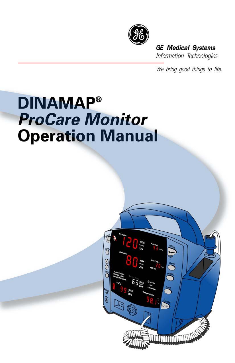
13 DINAMAP ProCare Monitor Operation Manual This manual is for DINAMAP ProCare Monitors models 100, 200, 300, and 400, with or without printers. ProCare 100: BP, Pulse ProCare 200: BP, Pulse, and Temp ProCare 300: BP, Pulse, and SpO 2 ProCare 400: BP, Pulse, Temp, and SpO 2 The model of the Monitor determines which parameters are in your monitor. Please refer to applicable sections. Reissues and Updates Changes occurring between issues are addressed through Change Information Sheets, Addendums, and replacement pages. If a Change Information Sheet does not accompany this manual, it is correct as printed. Errors and Omissions If errors or omissions are found in this manual, please notify: GE Medical Systems Information Technologies Technical Publications 4502 Woodland Corporate Boulevard Tampa, FL Part No C The content of this document including all figures and drawings is proprietary information of GE Medical Systems Information Technologies, provided solely for purposes of operation, maintenance or repair, and dissemination for other purposes or copying thereof is prohibited without prior written consent by GE Medical Systems Information Technologies, Tampa, Florida. Illustrations may show design models; production units may incorporate changes. 3
14 Hierarchy of Warnings and Cautions A general warning is a statement that alerts the user to the possibility of injury, death, or other serious adverse reactions associated with the misuse of the device. A warning relates to steps in a procedure. A general caution is a statement that alerts the user to the possibility of a problem with the device associated with its use or misuse. Such problems include device malfunction, device failure, damage to the device or damage to other property. A caution relates to steps in a procedure. Copyright 2002, GE Medical Systems Information Technologies. All rights reserved. World Headquarters GE Medical Systems Information Technologies, Inc West Tower Avenue Milwaukee, WI USA Tel: (US only) Fax: European Representative GE Medical Systems Information Technologies GmbH Munzinger Straße 3-5 D Freiburg Germany Tel: Fax: Asia Headquarters GE Medical Systems Information Technologies Asia; GE (China) Co., Ltd. 24th Floor, Shanghai MAXDO Center, 8 Xing Yi Road, Hong Qiao Development Zone Shanghai , P.R. China Tel: Fax:
15 Introduction
16 6
17 Introduction About the DINAMAP ProCare Monitor The ProCare Monitor provides a small, portable, easy-to-use monitoring alternative for sub-acute hospital and nonhospital settings. The battery-operated Monitor offers noninvasive determination of systolic blood pressure, diastolic blood pressure, mean arterial pressure, pulse rate, oxygen saturation, and temperature. Monitors are available with or without integrated printers. ProCare Monitors are intended for use in various markets, from the physician s office to sub-acute triage and medical/surgical units. ProCare 100: BP, Pulse ProCare 200: BP, Pulse, and Temp ProCare 300: BP, Pulse, and SpO 2 ProCare 400: BP, Pulse, Temp, and SpO 2 The model of the Monitor determines which parameters are in your monitor. Please refer to applicable sections. Using the ProCare Monitor, a clinician can view, print, and recall clinical data that is derived from each parameter. The Monitor is also capable of alerting the clinician to changes in the patient s condition or when it is unable to effectively monitor the patient s condition. All of the main operations of the ProCare Monitor are easy-to-use and only a button-touch away. Please review the factory default settings and, where applicable, enter settings appropriate for your use. Indications The ProCare Monitor is intended to monitor one patient at a time in a clinical setting. Contraindications This device is not designed, sold, or intended for use except as indicated. Federal law (U.S.A.) restricts this device to sale by or on the order of a physician. 7
18 Warnings Do not use the ProCare Monitor in the presence of magnetic resonance imaging (MRI) devices. There have been reports of sensors causing patient burns when operating in an MRI environment. Do not use the Monitor in the presence of flammable anesthetics. To help prevent unintended current return paths with the use of high frequency (HF) surgical equipment, ensure that the HF surgical neutral electrode is properly connected. To avoid personal injury, do not perform any servicing unless qualified to do so. WARNING: These Monitors should not be used on patients who are connected to cardiopulmonary bypass machines. If powering the Monitor from an external power adapter or converter, use only GE Medical Systems Information Technologies-approved power adapters and converters. The Monitor does not include any user-replaceable fuses. Refer servicing to qualified service personnel. To reduce the risk of electric shock, do not remove the cover or the back. Refer servicing to a qualified service person. If the accuracy of any determination reading is questionable, first check the patient s vital signs by alternate means and then check the ProCare Monitor for proper functioning. Use of portable phones or other radio frequency (RF) emitting equipment near the system may cause unexpected or adverse operation. The equipment or system should not be used adjacent to, or stacked with, other equipment. If adjacent or stacked use is necessary, the equipment or system should be tested to verify normal operation in the configuration in which it is being used. The use of accessories, transducers and cables other than those specified may result in increased emissions or decreased immunity performance of the equipment or system. 8
19 Cautions Do not use replacement batteries other than the type supplied with the Monitor. Replacement batteries are available from GE Medical Systems - Accessories and Supplies. The ProCare Monitor is designed to conform to Electromagnetic Compatibility (EMC) standard IEC , 1993 and will operate accurately in conjunction with other medical equipment which also meets this requirement. To avoid interference problems affecting the Monitor, do not use the Monitor in the presence of equipment which does not conform to these specifications. Place the ProCare Monitor on a rigid, secure surface. Monitor must only be used with mounting hardware, poles, and stands recommended by GE Medical Systems Information Technologies. The weight of the accessory basket contents should not exceed 5 lb (2.7kg). Arrange the external AC/DC power converter, air hoses, and all cables carefully so they do not constitute a hazard. Verify calibration of BP parameter (temp and pulse oximeter do not require calibration). Ensure that the display is functioning properly before operating the ProCare Monitor. Do not immerse the Monitor in water. If the Monitor is splashed with water or becomes wet, wipe it immediately with a dry cloth. Do not gas sterilize or autoclave. The ProCare Monitor, when used with GE Medical Systems Information Technologies-approved applied parts and accessories, is protected against defibrillator damage. Note The electromagnetic compatibility profile of the ProCare Monitor may change if accessories other than those specified for use with the ProCare Monitor are used. 9 Introduction
20 Product Compliance The DINAMAP ProCare Monitor is classified in the following categories for compliance with IEC 601-1: Internally powered or Class II when powered from external supply Transportable For continuous operation Not suitable for use in the presence of flammable anesthetics Not for use in the presence of an oxygen-enriched atmosphere (oxygen tent) Type BF applied parts IPX1, degree of protection against ingress of water Sterilization/Disinfection, see Appendix B Software is developed in accordance with IEC This equipment is suitable for connection to public mains via power adaptors as defined in CISPR 11. The SpO 2 parameter conforms to EN 865:1997 with the exception of Clauses 36, 48, sub-clause and to ISO Defibrillation protected. When used with the recommended accessories, the Monitor is protected against the effects of defibrillator discharge. If monitoring is disrupted by the defibrillation, the Monitor will recover. DINAMAP PROCARE MONITOR CLASSIFIED WITH RESPECT TO ELECTRIC SHOCK, FIRE AND MECHANICAL AND OTHER SPECIFIED HAZARDS ONLY IN ACCORDANCE WITH CAN/CSA C22.2 NO ALSO EVALUATED TO IEC This product conforms with the essential requirements of the Medical Device Directive. Accessories without the CE mark are not guaranteed to meet the Essential Requirements of the Medical Device Directive. 10
21 Symbols The following symbols are associated with the ProCare Monitor. Note: The model of the Monitor determines which symbols appear on it. Attention, consult accompanying documents Silence Alarms + / - Increase / decrease adjustable settings Menu Inflate/Stop Cycle History Print On/Off Battery Power External communications port connector Charging Defibrillator-proof type BF equipment External DC power input Class II equipment according to IEC

22 Packaging label depicting the transportation and storage atmospheric pressure range of 500 to 1060 hpa. IPX1 The DINAMAP ProCare Monitor is protected against vertically falling drops of water and conforms with the IEC 529 standard at level of IPX1. Vertically falling drops shall have no harmful effects to the Monitor. 12
23 Getting Started
24 14

25 Getting Started Unpacking the Monitor and Accessories Before attempting to use the ProCare Monitor, take a few minutes to become acquainted with the Monitor and its accessories. Unpack the items carefully. This is also a good time to check for any damage or accessory shortage. If there is a problem or shortage, contact GE Medical Systems Information Technologies. It is recommended that all the packaging be retained, in case the Monitor must be returned for service in the future. Setting up BP Connections 1. Connect the end of the air hose that has quick-release clips to the BP connector on the front of the Monitor. Make sure that the hose is not kinked or compressed. Note: To disconnect the hose from the Monitor, squeeze the quick-release clips together and pull the plug from the BP connector. 2. Select appropriate cuff size. Measure patient s limb and select appropriately sized cuff according to size marked on cuff or cuff packaging. When cuff sizes overlap for a specified circumference, choose the larger size cuff. Precaution: Accuracy depends on use of proper size cuff. 3. Inspect cuff for damage. Replace cuff when aging, tearing, or weak closure is apparent. Do not inflate cuff when unwrapped. Precaution: Do not use cuff if damaged. 4. Connect the cuff to the air hose. Refer to the BP section for complete cuff connection instructions. Warning: It is mandatory that the appropriate hose and cuff combination be used. Any attempt to modify the hose will inhibit the Monitor from switching between the neonatal and adult measurement modes. Note: Care should be taken in reconnecting the cuff to a hose, ensuring that threads of the cuff and hose are in alignment and no cross-threading occurs. 15


26 5. Refer to the BP section of this manual for complete instructions on taking an accurate BP determination. Note: Use only CRITIKON Blood Pressure Cuffs. The size, shape, and bladder characteristics can affect the performance of the instrument. Inaccurate readings may occur unless CRITIKON Blood Pressure Cuffs are used. Refer to Appendix E for reorder codes. Setting up SpO2 Connections 1. Plug the appropriate SpO 2 sensor into the SpO 2 sensor extension cable. 2. Then plug the SpO 2 sensor extension cable into the SpO 2 sensor connector on the Monitor. 3. Refer to the applicable SpO 2 section of this manual for complete instructions on monitoring SpO 2. Setting up Temperature Connections 1. Connect the temperature probe cable to the temperature probe connector on the Monitor. 2. Insert the temperature probe into the probe holster at the side of the Monitor. 3. Refer to the TURBO TEMP section of this manual for complete instructions on taking a temperature reading. 16


27 Getting Started Setting up the Printer (Installing the Paper) 1. With the Monitor powered on, turn it so that the side with the printer is facing you. 2. While grasping the side of the Monitor, lift the printer door open by placing your thumb in the indented area and pulling. The printer door will pop open. 3.Place the roll of paper into the compartment so that the end of the paper comes off the right-side of the roll (paper is wound around the roll clockwise). Push the roll all the way to the back of the printer cavity, making sure the paper extends out of the printer cavity at least two inches. 4.Firmly press the door to close it. 5.Refer to the Printer section of this manual for complete instructions. Power Sources The ProCare Monitor is designed to operate from an internal leadacid battery (see Specifications in Product Overview section). Notes The ProCare Monitor is not designed to operate without an internal battery. Be sure to unplug the Monitor before transport. Powering the Monitor: Battery and DC Supply Prior to each use, inspect the power supply cord to ensure proper connection and condition. Before the ProCare Monitor is used for the first time, the battery should be charged in the Monitor for at least 8 hours. 17

28 With external DC power connected, the green CHARGING indicator will light to indicate that the battery is charging. When the Monitor is operating on battery power and the BATTERY LOW alarm is not active, the BATTERY indicator is backlit green. When the Monitor is operating on battery power and the BATTERY LOW alarm is active, the BATTERY indicator flashes green, the LOW indicator flashes amber, and the medium priority alarm sounds until it is acknowledged. Press the Silence button to acknowledge this alarm. Once it is acknowledged, the indicators continue to flash, but the audible alarm is silenced for 10 minutes. Once the BATTERY LOW condition becomes active, the Monitor should be connected to a DC power supply to recharge the battery (refer to Power Requirements in Product Overview section). If the Monitor continues to be used without charging the battery, the Monitor eventually enters a fail-safe mode (E13: BATTERY TOO LOW TO OPERATE). Refer to the Alarms Section for information of an E13 error code. Battery charging will take place as long as the Monitor remains connected to an external DC power source. Notes To prolong the life of the battery, keep the Monitor connected to a DC power supply whenever possible. NEVER allow the battery to become completely discharged. A fully charged battery will power the Monitor for approximately 5 hours. To ensure full charge cycles, replace only with a recommended battery. If the Monitor is to be stored for some time, first charge the battery and then remove it and store it separately from the Monitor. 18
29 Turning the Monitor On and Off Getting Started To turn the ProCare Monitor on, push the power On/Off button. As the Monitor powers up, it will run a short self-test routine, which will flash all the indicator lights and then beep the warning speaker. To turn the Monitor off, push the power On/Off button again. This will terminate any measurements that may be in progress and automatically deflate the cuff. Note: Pressing and holding the On/Off button for 15 seconds will reset the CPU processor. After resetting the CPU processor, check all the unit configuration settings. Configuration Mode Settings Monitor settings such as HIGH/LOW alarm settings changed in the Clinical Mode will not be retained after the monitor is powered off. To retain alarm and parameter settings, the changes must be done in the configuration mode. Date/Time settings are also entered in the configuration mode. To enter the configuration mode: with the Monitor off, press and hold the Menu button at the same time as pressing and holding the On/Off button for 3 seconds. The Monitor enters the configuration mode. As the monitor turns on in the configuration mode, a brief display appears showing the software revision and the BP technology of the Monitor. These displays appear only during the first part of the power up sequence and are not selectable and cannot be changed. Display Major software revision Minor software revision Type of BP technology Window Systolic Diastolic min 19
30 The Menu selections appear in the following order. Refer the each manual section for settings options. Note: Menu selections for a Masimo unit have three SpO 2 settings. Refer to the Masimo SpO 2 section for options. Setting: Window LED Display Inflate Pressure: Diastolic XXX (numeric) SpO 2 Mode: SpO 2 SpO 2 Sat: SpO 2 SpO 2 * Sensitivity: SpO 2 Temp: C or F Year: Systolic Month: MAP/Cuff Day: Diastolic Hour: min Minute: min Mode: Systolic *Masimo units only Setting the Date and Time To set the date and time on the ProCare Monitor, you must access the configuration mode. Press MENU to skip the default settings that do not require changes. The following list shows the windows in which the date/time settings appear. Setting: Window LED Display Year: Systolic Month: MAP/Cuff Day: Diastolic Hour: min Minute: min Procedures 1. Press the Menu button to move from one setting to another. Use the +/- buttons to increment or decrement the setting. 20
31 Getting Started Note: For the date and time to be saved, you must advance the menu through the minute setting. 2. To exit the configuration mode, press the ON/OFF button. 3. To continue with other changes, press the Menu button. CFG will appear in the Systolic window. To change parameter settings, press the Menu button and select the parameter function. To change alarm settings, press the Alarms button. Inflation Pressure Default Settings (Refer to the BP Section for options) Procedures 1. Enter the configuration mode: with the Monitor off, press and hold the Menu button at the same time as pressing and holding the On/Off button for 3 seconds, or press Menu until the Inflate Pressure is lit on the display and the pressure is displayed in the Diastolic window. 2. Use the +/- buttons to increment or decrement the inflate pressure default setting. Increments are 5mmhg from 100mmhg to 250mmhg. 3. To exit the configuration mode, turn the unit off. To continue with additional configuration settings, press Menu. Alarm Default Settings (Refer to Alarms Section for options) Procedures 1. Enter the configuration mode: with the Monitor off, press and hold the Menu button at the same time as pressing and holding the On/Off button for 3 seconds. After the unit enters the configuration mode, press Alarms. At any point in the configuration mode menu, Alarms default may be selected. 2. To set or change the default setting, press the Alarms button to select alarm setting. Use the +/- buttons to increment or decrement the individual settings. Note: For the Alarms default setting to be saved, you must advance the menu through the SPO2 settings. 3. To exit the configuration mode, turn the unit off. To continue with additional configuration settings, press Menu. 21
32 SPO 2 Configuration Settings Procedure for units with Nellcor Technology (Refer to the Nellcor section for options) 1. Enter the configuration mode: with the Monitor off, press and hold the Menu button at the same time as pressing and holding the On/Off button for 3 seconds. 2. Press the menu button until n0d appears in the Pulse Rate window. 3. Use the +/- buttons to select the option. 4. Press the Menu button once. SAt appears in the Pulse Rate window. 5. Use the +/- buttons to select the option. 6. To exit the configuration mode, turn the unit off. To continue with additional configuration settings, press Menu. Procedure for units with Masimo Technology (Refer to the Masimo section for options) 1. Enter the configuration mode: with the Monitor off, press and hold the Menu button at the same time as pressing and holding the On/Off button for 3 seconds. 2. Press the Menu button until n0d appears in the Pulse Rate window. 3. Use the +/- buttons to select the option. 4. Press the Menu button once. SAt appears in the Pulse Rate window. 5. Use the +/- buttons to select the option. 6. Press the Menu button once. SEn appears in the Pulse Rate window. 7. Use the +/- buttons to select the option. 8. To exit the configuration mode, turn the unit off. To continue with additional configuration settings, press Menu. 22
33 Product Overview
34 24
35 Product Overview Buttons 1 Silence button: Press to mute audible alarms. Any alarm active that is acknowledgeable is also removed whenever this key is pressed. When pressed after alarm sounds (silence active), the silence icon (bell) lights to indicate that audible alarms have been silenced for 2 minutes 2 Alarms button: Press to view or adjust parameter alarm settings 3 +/- button (Plus/Minus): Press the + button to increase an adjustable setting and the - button to decrease an adjustable setting. This button is active only when a usersetting mode (limit or menu) is active 4 Menu button: Press to access menu settings that can be adjusted while in clinical mode (i.e., ALARM VOLUME, PULSE VOLUME, INFLATE PRESSURE; refer to Operating Modes in this section for a description of clinical mode) 5 SpO 2 sensor connector: SpO 2 sensor extension cable attaches here 6 BP connector: BP cuff hose attaches here 7 Inflate/Stop button: Press to start a manual BP determination or stop any BP determination 8 Temperature probe holster: Temperature probe is stored here 9 Cycle button: Press to start Auto Cycle or STAT mode 25
36 10 Temperature probe cover storage: Box of probe covers is stored here 11 History button: Press to activate the history mode. When activated, it displays the most recent entries stored. Press and hold the button for 2 seconds to clear all entries stored 12 Print button: Press to print currently displayed values or all stored entries when in history mode 13 On/Off button: Controls on/off state of monitor; push for power on and push again for power off 14 Temperature probe connector: Temperature probe cable attaches here 26
37 Product Overview Front Panel 15 Silence icon: when Silence button is pressed after alarm sounds (silence active), silence icon (bell) lights to indicate that audible alarms have been silenced for 2 minutes 16 Systolic window: 3-digit red LED indicates measured systolic BP in mmhg 17 Diastolic window: 3-digit red LED indicates measured diastolic BP in mmhg 18 Alarm volume indicator: lights to indicate you are making a change to the alarm volume 19 Pulse volume: lights to indicate you are making a change to the pulse volume 20 Inflate pressure: lights to indicate you are making a change to the inflation pressure 21 Pulse Rate window: 3-digit yellow LED shows pulse rate in beats per minute 22 SpO 2 pulse indicator: Red LED bar flashes to indicate that real-time pulse rate measurements are being derived from SpO 2 signals 23 SpO 2 window: 3-digit red LED indicates oxygen saturation in % 27
38 24 MAP/Cuff window: 3-digit red LED indicates measured MAP in mmhg and shows instantaneous cuff pressure during BP determination 25 Min window: Displays the BP mode if manual or STAT is the cycle time when in Auto Cycle mode 26 Battery power indicator: Green LED indicates the Monitor is operating on battery power 27 Low battery power indicator: Yellow LED indicates LOW charge status of internal battery 28 Charging indicator: Green LED indicates presence of external power source and battery charging 29 Temperature window: 4-digit red LED indicates measured temperature 28
39 Product Overview Rear Panel 30 Data interface connector: Host communications port (15 pin D-type RS-232 serial port) for use only with equipment conforming to IEC 601-1, configured to comply with IEC Printer compartment 29
40 Left-Side Panel 32 Printer compartment Right-Side Panel 33 External DC power socket: To be used with approved GE Medical Systems Information Technologies AC-DC power converter ONLY 30
41 Product Overview Windows Each derived vital sign has an associated window for displaying the value. For each window, the vital sign s name and unit of measure are labeled above and to the right of it, respectively. An additional window--the min window--is available for displaying the BP mode or chosen AUTO CYCLE selection. Indicators Indicators are text messages and icons that are positioned on the front of the Monitor and can be either backlit red or green. For each vital sign that has user-adjustable limits, two indicators (HIGH, LOW) appear to the right of its window. Operating Modes The ProCare Monitor can operate in one of four modes: clinical, configuration, advanced configuration, and service. Clinical mode is the Monitor s normal operating mode. While this mode is active, alarm limits and a few other commonly used settings are adjustable. All parameters are available for monitoring in this mode. Configuration and advanced configuration modes display the software revision and allows you to configure defaults for some settings that are available in clinical mode, as well as some less commonly used settings that are only adjustable in these modes. No parameters are operable in these modes, therefore, patient monitoring should be suspended. Entering Configuration Mode 1. With the Monitor off, press and hold the Menu button at the same time as pressing the On/Off button for 3 seconds. 2. The Monitor automatically switches on in configuration mode. Refer to the Service Manual for instructions for use concerning advanced configuration and service mode. 31
42 Parameter Modes The ProCare Monitor has three parameter modes: offline, ready, or operate. A parameter is in offline mode when its vital sign(s) are not checked against user-set limits, alarm conditions detected by the parameter do not generate alarms, and no vital sign(s) data is displayed. A parameter is in ready mode when its vital signs are not checked against user-set limits, alarm conditions detected by the parameter do not generate alarms, and no vital sign(s) data is displayed. However, information regarding the connection of a sensor is communicated in this mode. A parameter is in operate mode when the appropriate vital signs are being checked against user-set limits and alarming conditions detected by the parameter generate alarms. Vital sign(s) data from the parameter is displayed. When the Monitor is turned on and no sensor is connected, the parameter remains in offline mode. Upon detection of a sensor, the parameter auto-switches to ready mode. Upon detection of valid patient data, the parameter auto-switches to operate mode. User Modes The ProCare Monitor has four user modes that are available during clinical operating mode: Menu, Cycle, Limit Adjustment, and History. The Menu mode allows you to access and change the three settings associated with the following indicators: ALARM VOLUME, PULSE VOLUME, AND INFLATE PRESSURE. To activate this mode, press the Menu button. With each press of the Menu button, the indicator appears in flashing green with the associated value appearing in red in the Diastolic window. As the Menu button is pressed, the indicators appear in the following order: ALARM VOLUME, PULSE VOLUME, AND INFLATE PRESSURE. To change the associated value, simply use the +/- button to increment or decrement, respectively. After 15 seconds of not pressing the 32
43 Product Overview Menu button, the Menu mode is automatically exited. Otherwise, you can exit the Menu mode by pressing the Menu button one more time after viewing the oldest entry. Upon exiting Menu mode, the main monitoring screen is displayed. Alarm and pulse volume settings are retained after power-off. INFLATE PRESSURE is reset to its configured default after power-off. The Cycle mode allows you to access Auto Cycle and STAT modes. Refer to the BP section for more information. The History mode allows you to access the stored patient data. Refer to the History section for more information. The Limit Adjustment mode allows you to change alarm limit settings that are used while monitoring a patient. All limit alarm settings return to their default settings after power-off. The range and increment/decrement steps for each derived vital sign that has adjustable limits are described in each parameter section. The step size specified (which cannot be adjusted) tells how much the limit value will change per increment/decrement key press and also dictates how close together a pair of limits can be. Limit-adjustable vital signs are displayed in the following order: Systolic (HIGH, LOW), Diastolic (HIGH, LOW), Pulse Rate (HIGH, LOW), and SpO 2 (HIGH, LOW). Note: The Temperature and MAP (mean arterial pressure) vital signs are not checked against alarm limits. Sounds The Monitor generates sounds based upon user interaction, parameter events, parameter and system alarms, and low battery alarms. User interaction sounds include positive key tone and negative key tone. The positive key tone sounds one highpitched tone when you press a button and the Monitor is able to perform the intended function. The negative key tone sounds three low-pitched tones when you press a button and the Monitor is unable to perform the intended function. 33
44 Parameter-specific sounds are related to the functioning of each parameter: NIBP, Temperature, and SpO 2. Refer to the individual parameter sections for definitions and sounds. Alarm-specific sounds include medium and high priority. The medium-priority alarm sounds three high-pitched tones. The high-priority alarm sounds three high-pitched tones followed by two high-pitched tones. When alarms of both priorities are active, only the high-priority alarm sound is audible. A sound is generated when AC power is lost while patient monitoring is active. Power Sources The ProCare Monitor is designed to operate from an internal lead-acid battery. For replacement rechargeable batteries, please refer to the Service section of this manual. 34
45 Specifications Mechanical Dimensions Product Overview Height: 9.7 in (24.7 cm) Width: 8.6 in (21.9 cm) without Temperature 10.0 in (25.4 cm) with Temp Depth: 5.3 in (13.5 cm) Weight, Including Battery Mountings Portability Classification Information 5.68 lb (2.58 kg) Self-supporting on rubber feet Carried by handle Mode of operation: continuous Degree of protection against harmful ingress of water: Dripproof IPX1 Power Requirements Power Converter US: P/N: Protection against electrical shock: Class II AC input: 120 VAC/60 Hz 24W DC output voltage; 12VDC at 1A The AC mains power adapter contains a nonresettable and nonreplaceable fuse. Power Converter UK & EUR: P/N UK: P/N EUR: Protection against electrical shock: Class II AC input: VAC/50 Hz 92mA DC output voltage; 12VDC at 1A 35
46 The AC mains power adapter contains a nonresettable and nonreplaceable fuse. Monitor Protection against electrical shock: Internally powered or Class II when powered from specified external power supply. DC input voltage: 12 VDC, supplied from a source conforming to IEC Fuses: The Monitor contains four fuses. The fuses are autoresettable and mounted within the Monitor. The fuses protect the low voltage DC input, the battery, the remote alarm output, and the +5 V output on the host port connector. Battery: 6 volt, 3.3 amp-hours protected by internal autoresetting fuse and thermal protection. Minimum operation time: 5 hrs (5 min cycle with adult cuff at 25 C, SpO 2 active at 60 bpm, Temp in monitor mode) from full charge. Time for full recharge: Approx. 5 hrs from full discharge when the Monitor is switched off and approx. 8 hrs when the Monitor is switched on. Environmental Operating Temperature + 5 C to + 40 C (+ 41 F to F) Operating Atmospheric Pressure 700 hpa to 1060 hpa 36
47 Product Overview Storage Temperature 20 C to + 50 C ( 4 F to F) Storage/Transportation Atmospheric Pressure Humidity Range Radio Frequency 500 hpa to 1060 hpa 5% to 95% noncondensing Complies with IEC Publication (April 1993) Medical Electrical Equipment, Electromagnetic Compatibility Requirements and Tests and CISPR 11 (Group 1, Class B) for radiated and conducted emissions. IPX1 The DINAMAP ProCare Monitor is protected against vertically falling drops of water and conforms with the IEC 529 standard at level of IPX1. No harmful effects will come of vertically falling drops of water making contact with the Monitor. 37
48 38
49 Printer
50 40
51 41 Printer Description The ProCare Monitor comes with an optional text-only printer. Each time a printout is started, the following information is printed: GE Medical Systems header, monitor name; model number; current software revision; a place for patient name and hand-written comments; a place for the column labels, parameter labels, or unit of measure; date; and vital signs data, if available. On some models, a pencil icon appears instead of the name and comments labels. Installing the Paper Refer to the Getting Started section for instructions. Print Button The Print button initiates two types of printouts: currently displayed values and History. By pressing the Print button while the main monitoring screen is viewable, a printout of the currently displayed values is generated. Since the currently displayed values may have been derived at different times (e.g., the BP values are 5 minutes old, while Temp was just completed), the Monitor prints the value along with a time stamp of when that value was derived. Values are printed in order of the most recent to the oldest. By pressing the Print button when in History mode, all entries currently stored in the history are printed in order of the most recent to the oldest. Note: If the Print button was pressed during the first 10 seconds of SpO 2 monitoring, dashes will appear for SpO 2 and pulse rate readings. The availability of the printer is determined at the time the printout is started. When the printer is unavailable, the Print button makes a negative key sound when you press it. The printer is unavailable if it is out of paper, too hot, or if the battery is too low, or if the Monitor is in any of the following modes: Cycle, Alarm limit adjustment, Menu, config, or service. If no print is visible on the paper, check that the paper roll has been installed in the correct position (refer to diagram).
52 To tear off the printout, use a slight sideways action to pull the paper sharply up across the edge of the door. Printer Alarms When any of the alarm conditions occur, the alarm code flashes in the min window and a high-priority alarm sounds. When a printer alarm condition is active, you can acknowledge the alarm by pressing the Silence button. E10: PRINTER NO PAPER This alarm is generated when the Print button is pressed and the printer detects that there is no paper. E11: PRINTER TOO HOT This alarm is generated when a printout is in progress and the printer becomes too hot to print. E12: BATTERY TOO LOW TO PRINT This alarm is generated when a printout is in progress and the battery becomes too low to print. Storage Store thermal paper in a cool, dry place. The printed strip (thermal paper recording) should not be exposed to direct sunlight, exposed to temperatures over 100 F/38 C or relative humidity over 80%, placed in contact with adhesives, adhesive tapes, or plasticizers such as those found in all PVC page protectors. Note: When in doubt about long-term storage conditions, store a photocopy of the thermal paper recording. Cautions The paper is thermally activated; therefore, do not store it in a hot place as discoloration may result. Use only replacement paper rolls (P/N for single rolls, for box of 10) from GE Medical Systems - Accessories and Supplies. 42
53 Alarms
54 44
55 45 Alarms The ProCare Monitor provides visible and audible indications of patient-, and system-related alarm conditions. An alarm can generate an audible indication, visual indication, alarm message code, and electronic record in the history. Alarm Codes All alarm indications are accompanied by an audible signal unless the Silence button is selected. A microprocessor system failure will generate a high-pitched audible alarm regardless of the setting of the Silence button. There are three categories of alarms: patient-related (limit and parameter status alarms), system-related (printer, battery, and memory alarms), and system failures. Adjusting Alarm Limits Alarms Button Pressing the Alarms button activates the limit adjustment user mode. When the limit adjustment mode is initially activated, it first displays the systolic high limit value with the HIGH indicator flashing in red. With each subsequent press of the Alarms button, the next limit in the sequence is displayed for adjustment. Press the + button to increase the displayed limit value and the - button to decrease the displayed limit value. To exit limit adjustment mode after setting alarms, you must progress through all limits until you reach the last one. Then, after reaching the last limit, immediately press the Alarms button. The main monitoring screen appears indicating that you have exited Alarms mode. If monitoring is active, the current vital signs appear after you have completed your alarm setting changes. Or, you can let the mode time-out by not touching the Alarms button until the main monitoring screen appears indicating that you have exited Alarms mode. The Monitor returns to all default limit settings after poweroff; these defaults are adjustable via configuration mode. Adjustable vital signs limits are displayed in the following order: Systolic (HIGH, LOW), Diastolic (HIGH, LOW), Pulse Rate (HIGH, LOW), and SpO 2 (HIGH, LOW). Refer to each parameter section for ranges.
56 Note: The Temperature and MAP vital signs are not checked against alarm limits. Adjusting the Alarm Volume You can adjust the alarm volume by pressing the Menu button. ALARM VOLUME will flash in green with the value in the Diastolic window. You can set the ALARM VOLUME range from 1 to 10 (10 being the loudest). Changing the volume applies to all alarms. The positive key tone that sounds when you press the +/- buttons relates directly to the user-set alarm volume. Refer to User Modes. Silencing and Acknowledging an Alarm Silence Button To silence a patient-related alarm (limit and parameter status alarms) at anytime, press the Silence button. The silence icon (a bell) lights to indicate that audible alarms have been silenced for 2 minutes. Some patient- and system-related alarms are acknowledgeable. (Refer to the Alarm Message Codes table at the back of this section.) For acknowledgeable alarms that are active when the Silence button is pressed, any associated audible or visual indication is removed and any associated alarm message code is no longer displayed. The silence icon has three states: Solid red: silence icon is active. Blinking red: alarm silence is not active and at least one alarm condition is active. Off: alarm silence is not active and no alarm condition is active. Alarm Sounds The Monitor produces two different alarm sounds based upon the priority of the alarm: medium and high priority. The medium-priority alarm sounds three high-pitched tones. The high-priority alarm sounds three high-pitched tones followed 46
57 Alarms by two high-pitched tones. When alarms of both priorities are active, only the high-priority alarm sound is audible. Alarm Detection and Priorities Limit Alarms The Monitor checks each derived vital sign (except MAP and Temperature) against user-set limits. A high-limit alarm is generated when that value is greater than its high limit. A low-limit alarm is generated when that value is less than its low limit. All limit alarms are considered high priority. Parameter Range Factory Default* Systolic High Systolic Low Diastolic High Diastolic Low Pulse Rate High: NELLCOR Pulse Rate Low: NELLCOR Pulse Rate High: MASIMO Pulse Rate Low: MASIMO SpO 2 High SpO 2 Low *To change Alarm Default settings, refer to Config Mode in Getting Started section. When a limit violation occurs, the following happens: The derived vital sign that is out of limits and the associated HIGH or LOW indicator flash. The high priority alarm sound becomes audible unless silence is active. 47
58 Parameter Status Alarms The Monitor generates parameter status alarms when unusual patient or sensor conditions are detected. All parameter status alarms are considered high priority alarms. Refer to the Alarm Message Codes table in this section. When a parameter status alarm occurs, the following happens: Its code flashes in the associated window. The high priority alarm sound becomes audible unless alarm silence is active. Printer Alarms Refer to Printer section. Memory Alarms Memory alarms occur when battery-backed RAM is corrupted. When it occurs, all settings are reset to their factory defaults. When detected, the alarm message code appears in the Systolic window and the medium-priority alarm sounds. Battery Alarms Two types of battery alarms exist: a BATTERY LOW alarm indicating the battery needs recharging and an E13 BATTERY TOO LOW TO OPERATE indicating that the battery is so low monitoring has stopped. For information on the BATTERY LOW alarm, refer to Powering the Monitor in the Getting Started section. When the E13 BATTERY TOO LOW TO OPERATE is detected, the Monitor ceases all monitoring, blanks the display except for the Low Battery indicators, and displays E13 in the Systolic window. A medium priority alarm sounds and continues to sound for 10 minutes, unless the unit is powered off. After the first 10 minutes, if the Monitor was idle (not monitoring) when the condition was detected, then it automatically powers off. 48
59 Alarms Otherwise, if the unit had been monitoring when the condition was detected, the alarm changes to the critical priority alarm level. The Monitor continues to display the Low Battery indicators and error code E13 as before. This continues for 10 minutes, unless the unit is powered off. At the end of this period, if the Monitor has not be shut off, it then automatically powers off. System Failure Alarms System failures are caused by a system software or hardware failure. When a system failure occurs, the error code is displayed in the Systolic window, and the Monitor enters a fail-safe mode in which a constant alarm tone sounds for up to 10 minutes before the tone is automatically switched off. Refer to the Alarm Message Codes table in this section. 49
60 Specifications Default Settings Alarm Volume 5 50
61 Alarms Alarm Message Code Alarm Detected Acknowledgeable by pressing Silence?* E89 BP NO DETERMINATION Yes E85 BP LEVEL TIMEOUT Yes E84 BP TOTAL TIMEOUT Yes E83 BP INFLATION TIMEOUT Yes E82 EXCESS AIR IN CUFF Yes E80 BP OVERPRESSURE Yes E21 SPO2 REPLACE SENSOR Yes E22 SPO2 REPOSITION SENSOR Yes (Masimo ONLY) E23 SPO2 SENSOR OFF FINGER Yes E25 SPO2 NO SIGNAL Yes E61 TEMP PROBE BROKEN No E63 TEMP DISCONNECTED OR WRONG TYPE PROBE Yes E66 TEMP PROBE TOO HOT No E10 PRINTER NO PAPER Yes E11 PRINTER TOO HOT Yes E12 BATTERY TOO LOW TO PRINT Yes E13 BATTERY TOO LOW TO OPERATE No 51
62 E00 MEMORY LOST Yes Alarm Message Code Alarm Detected SYSTEM FAILURE** SpO 2 no status from module for 30 ±10s, fatal error reported by module SYSTEM FAILURE** TEMP data samples less than 45 in 5s interval SYSTEM FAILURE** NIBP pump on during idle or overcurrent detected SYSTEM FAILURE** NIBP valve stuck closed during cuff typing SYSTEM FAILURE** NIBP PT2 higher than 150 for greater than 15s while idle SYSTEM FAILURE** Time base failure SYSTEM FAILURE** RAM test failure SYSTEM FAILURE** ROM checksum failure SYSTEM FAILURE** Secondary SPI communication error during initialization SYSTEM FAILURE** Calibration data invalid on initialization or unit never calibrated SYSTEM FAILURE** Calibration data storage exhausted while saving data in cal mode Acknowledgeable by pressing Silence?* No No No No No No No No No No No *Acknowledging an alarm by pressing the Silence button, cancels the alarm. ** Refer to the ProCare Service Manual or call Technical Support for definitions and instructions. 52
63 History
64 54
65 55 History Description The History mode allows you to access the stored patient data. The ProCare Monitor can hold up to 40 stored entries in history. When full, the oldest entry is removed so the most recent entry can be stored. Additionally, entries are automatically removed when they become older than 24 hours. The age of each entry is maintained and displayed in the min window with a minus sign (-) in front of it when other data stored for that entry is displayed. For entries that are greater than 59 minutes old, the age is displayed as HH:MM (hour:min). For entries that are less than or equal to 59 minutes old, the age is displayed in total minutes. When viewing entries in History that are out of limits, the corresponding HIGH or LOW indicator appears in red. An entry is stored in history at the completion of a BP determination and at the completion of a successful predictive temperature measurement. At the end of a BP determination, systolic, diastolic, MAP, pulse rate, and SpO 2 values are stored. At the end of a temperature determination, only the temperature value is stored. Buttons Associated with History To activate the History mode, press the History button. The HISTORY indicator flashes green while this mode is active. With each press of the History button, the patient data stored with the next oldest entry is displayed. Entries are displayed from the most recent to the oldest. For example, the most recent entry could have an age of -0 minutes and the oldest entry could have an age of -23:59. After 15 seconds of not pressing the History button, the History mode is automatically exited. Otherwise, you can exit the History mode by pressing the History button one more time after viewing the oldest entry. Upon exiting History mode, the main monitoring screen is displayed. Erasing Stored History To erase stored patient data, press and hold the History button for a minimum of 2 seconds. All entries that were
66 stored in history, as well as any patient data displayed on the Monitor that relates to the previous determination or the previous temperature measurement is erased. Windows Associated with History Each window on the Monitor can be active during History mode. When the History button is pressed the patient data stored for each entry is displayed in the applicable windows. Patient data is displayed from most recent to oldest, indicated by the age in the min window. Indicators Associated with History The History indicator is used to show the state of the history mode. When History mode is active, the History indicator flashes green. 56
67 BP
68 58
69 BP Description The BP parameter in the ProCare Monitor is available with two types of BP technologies: one calibrated to intra-arterial pressure and one calibrated to the auscultatory method (specific technologies are available in select markets). Please refer to the front of your ProCare Monitor to see which BP technology your monitor contains. The monitors containing auscultatory technology will have an auscultatory label above the model number on the front of the Monitor. Then, refer to the Appendix A: Principles of Noninvasive Blood Pressure Determination for specific information regarding both technologies. All user interface options, instructions for use, and alarms will be the same for both technologies. The BP parameter is included in all models. Blood pressure is monitored noninvasively in the ProCare Monitor by oscillometric method. Note: For neonatal populations, the reference is always the intra-arterial pressure monitoring method. The ProCare Monitor has three BP modes: 1. Manual, 2. Auto Cycle, and 3. STAT. The mode is selected by the user. The actual BP determination is automated and, once it is complete, the values for systolic pressure, diastolic pressure, mean arterial pressure, and pulse rate are shown in their respective windows. Before each BP determination, the Monitor performs a test to ensure that the cuff pressure is below a specified level. The determination is delayed until this condition is met. The Monitor senses the type of hose being used and automatically uses adult/pediatric monitoring parameters or neonatal monitoring parameters, as appropriate. Audible and visible alarms occur when any of the values for systolic pressure, diastolic pressure, or pulse rate are outside their selected high or low limits. Note: The Monitor will continue to operate until the battery is completely depleted in order to obtain the full use of the battery. However, if the battery reaches its empty point during a BP determination, it will simply stop in the middle of the determination. 59
70 Instructions for cleaning and disinfecting BP cuffs are in Appendix B. General Warnings Connect cuffs and inflation systems only to systems designed for non-invasive blood pressure monitoring. Devices with luers and locking luer connectors may be inadvertently connected to intravascular fluid systems that may allow air to be pumped into a blood vessel. The ProCare Monitor will not measure blood pressure effectively on patients who are experiencing seizures or tremors. Arrhythmias will increase the time required by the ProCare Monitor to determine a blood pressure and may extend the time beyond the capabilities of the Monitor. In Manual mode, the ProCare Monitor displays the results of the last blood pressure determination for 30 minutes or until another determination is completed. If a patient s condition changes between one determination and the next, the Monitor will not detect the change or indicate an alarm condition. Devices that exert pressure on tissue have been associated with purpura, skin avulsion, compartmental syndrome, ischemia and/or neuropathy. To minimize these potential problems, especially when monitoring at frequent intervals or over extended periods of time, make sure the cuff is applied appropriately and examine the cuff site and the limb distal to the cuff regularly for signs of impeded blood flow. Do not apply external pressure against cuff while monitoring. Doing so may cause inaccurate blood pressure values. Use care when placing cuff on extremity used to monitor other patient parameters. The ProCare Monitor is designed for use only with CRITIKON dual-tube cuffs. 60
71 61 BP Use only accessories approved for use with DINAMAP Monitors. Failure to use recommended accessories may result in inaccurate readings. Blood pressure cuffs should be removed from the patient when the Monitor is powered off. If the extremity remains cuffed under these conditions or if the interval between blood pressure determinations is prolonged, the patient s limb should be observed frequently and the cuff placement site should be rotated as needed. General Cautions Accuracy of BP measurement depends on using a cuff of the proper size. It is essential to measure the circumference of the limb and to select the proper size cuff. In addition, the air hoses are color-coded according to patient population. The gray 12- or 24-foot hose (3.66 m or 7.3 m) is required on patients who require cuff sizes from infant through thigh cuffs. The light blue 12-foot hose (3.66 m) is required for the neonatal cuff sizes #1 through #5. If it becomes necessary to move the cuff to another limb, make sure the appropriate size cuff is used. The pulse rate derived from a BP determination may differ from the heart rate derived from an EKG waveform because the ProCare Monitor measures actual peripheral pulses, not electrical signals or contractions from the heart. Differences may occur because electrical signals at the heart occasionally fail to produce a peripheral pulse or the patient may have poor peripheral perfusion. Also, if a patient s beat-tobeat pulse amplitude varies significantly (e.g., because of pulsus alternans, atrial fibrillation, or the use of a rapid-cycling artificial ventilator), blood pressure and pulse rate readings can be erratic, and an alternate measuring method should be used for confirmation. General Notes A patient s vital signs may vary dramatically during the use of cardiovascular agents such as those that raise or
72 lower blood pressure or those that increase or decrease heart rate. Several conditions may cause the BP parameter to calculate and display only the mean arterial pressure (MAP) without systolic and diastolic readings. These conditions include very low systolic and amplitude fluctuations, so an accurate calculation for these values can t be made (e.g., patient in shock); too small of a difference between systolic and MAP calculations in relationship to the difference between diastolic and MAP; or a leak has occurred in the ProCare Monitor. If only the MAP value is displayed, an alarm message code is displayed in the systolic window, while the diastolic window remains blank. This equipment is suitable for use in the presence of electrosurgery. Buttons Associated with BP The buttons associated with BP are Inflate/Stop and Cycle. The Inflate/Stop button starts and stops BP determinations. When a determination is in progress, pressing this button stops the determination. While in STAT mode, pressing this button cancels STAT mode, as well a determination if in progress. When in Auto Cycle mode, pressing this button starts a determination or cancels a determination if in progress; it does not change the mode. Note: While an E80: BP OVERPRESSURE alarm is active, all presses of this button are ignored. The Cycle button initiates the Cycle mode, which is where you can choose STAT or an auto cycle time. Cycle mode selections appear in the following order: Stat, 1, 2, 3, 4, 5, 10, 15, 20, 30, 60, 90, 120 (minutes), and - - (two dashes). Choose Stat to start STAT mode. Choose to select the desired cycle time and start Auto Cycle mode. When you reach the desired setting, do not press the Cycle button again. After 2 seconds the cycle mode is deactivated. Choose the two dashes to cancel Auto Cycle mode. Note: While an E80: BP OVERPRESSURE alarm is active, all presses of this button are ignored. 62
73 BP Windows Associated with BP The windows associated with BP are Systolic, Diastolic, MAP/Cuff, Pulse Rate, and min. The Systolic, Diastolic, MAP/Cuff, and Pulse Rate (if SpO 2 is not active) windows are automatically cleared when a new BP determination is started. In manual mode, the displayed information is also cleared when it becomes older than 30 minutes. The Systolic and Diastolic windows display values after a determination has completed successfully. While in STAT mode, the Systolic window flashes the early systolic value if it is available. The MAP/Cuff window displays the derived mean arterial pressure (MAP) following the completion of a successful determination. During any type of BP determination, the pressure inside the cuff appears in this window. The min window displays the BP mode of operation and the age of the previous BP determination. When both types of information are present, they flash alternately in this window. When in Manual mode, two dashes (- -) are displayed. When in Auto Cycle mode, the chosen Cycle time is displayed (e.g., 15) When in STAT mode, Stat is displayed. When displayed, the age of the previous BP determination is preceded by a minus sign (e.g., - 5). Indicators Associated with BP The indicators associated with BP are Systolic HIGH and LOW, Diastolic HIGH and LOW, AUTO CYCLE and HISTORY. The AUTO CYCLE indicator appears solid green when Auto mode is on. It flashes green when changes are being made to the current BP mode (e.g., Cycle mode is active). The HISTORY indicator appears solid green when the age of the previous BP determination is displayed in the min window. Parameter Modes The BP parameter is in operate mode upon power-up. It does not have a ready mode. 63
74 BP Modes of Operation The ProCare Monitor has three BP modes: 1. Manual, 2. Auto Cycle, and 3. STAT. The mode is selected by the user. BP determinations are automated and, upon completion, the values for systolic pressure, diastolic pressure, mean arterial pressure, and pulse rate are shown in their respective windows. Manual BP Determinations Manual mode allows you to take one blood pressure determination. Manual mode is always the BP mode of operation upon power-up. A normal, uninterrupted Manual determination takes about 40 seconds. Following a determination, the cuff pressure must drop below 5 mmhg (neonate) or 15 mmhg (adult) before another determination can be started. Manual BP determinations are started by pressing the Inflate/Stop button. To stop a Manual BP determination press the Inflate/Stop button. The values displayed in the Systolic, Diastolic, MAP, and Pulse Rate (if SpO 2 is not active) windows are cleared after 30 minutes have lapsed. Auto Cycle Determinations Auto Cycle mode allows you to take multiple determinations at user-defined intervals. In the Auto Cycle mode, the pressure must be below 5 mmhg (neonate) or 15 mmhg (adult) for at least 30 seconds before the next auto determination can be started. Auto Cycle mode is started by selecting the Cycle button. When in Auto Cycle mode, the AUTO CYCLE indicator appears solid green. Manual determinations can be taken while in Auto Cycle mode without affecting when the next auto determination is to start. You can also change the time interval while in Auto Cycle mode. Once the Cycle button is pressed, the first Auto Cycle determination is started, and the time between determinations appears in the min window. You can change the time interval between Auto Cycle determinations by continuing to press the Cycle button until you reach the 64
75 BP desired time interval. Time interval selections appear in the following order: Stat, 1, 2, 3, 4, 5, 10, 15, 20, 30, 60, 90, 120 (minutes), and - - (two dashes). When you reach the desired time interval, do not press the Cycle button again; after 2 seconds, the chosen time interval is retained and remains in the min window. Pressing the Cycle button when in Auto Cycle mode activates Cycle mode again with two dashes (- -) appearing in the min window. If you press the Cycle button immediately after the first press, the next time interval appears in the min window. If you do not press the Cycle button immediately after the first press, Cycle mode is deactivated. Press the Inflate/Stop button to stop the determination in progress without canceling the Auto Cycle mode. Choose the two dashes (- -) to cancel Auto Cycle mode. If the first Auto Cycle determination results in a limit alarm, another repeat determination is taken to verify the alarm. This occurs only once. Whenever an Auto Cycle determination results in a E89: BP NO DETERMINATION alarm, up to nine more repeat determinations are attempted in order to achieve valid values. If at any time during this repeat cycle, the BP NO DETERMINATION alarm is acknowledged by pressing the Silence button or the Inflate/Stop button, additional determinations are not attempted. If the repeat cycle completes all nine repeat determinations without reaching a valid value, the Monitor returns to normal Auto Cycle mode. However, an Auto Cycle mode determination must complete successfully before a repeat cycle will follow a future Auto Cycle mode determination that results in an E89: BP NO DETERMINATION alarm. STAT BP Determinations STAT mode allows you to take as many determinations as possible within a 5-minute time period. The Monitor will begin another determination once the pressure is below 5 mmhg for 8 seconds (neonates) or 15 mmhg for 4 seconds (adults), unless the 5-minute period has ended or STAT mode has been canceled. 65
76 Note: BP and BP-derived pulse rate alarm limits are disabled while in Stat mode. STAT BP determinations are started by selecting the Cycle button. Once the Cycle button is pressed, choose Stat. The Monitor automatically begins a 5-minute period of STAT determinations. Note: If the Monitor was previously in Auto mode, the first STAT BP determination begins after 2 seconds. After the first STAT determination, an early systolic value flashes in the associated window. If STAT mode is started when a determination is already in progress, that determination becomes the first in the series of STAT determinations. At the end of STAT mode, the BP mode prior to entering STAT mode is resumed. To cancel STAT mode, press the Inflate/Stop button. User Settings Mode Settings There is one mode setting associated with this parameter: Cycle. The Cycle mode is started by pressing the Cycle button. While the Cycle mode is active, Cycle selections are displayed in the min window. Cycle selections appear in the following order: Stat, 1, 2, 3, 4, 5, 10, 15, 20, 30, 60, 90, 120, - -. Limit Settings There are two limit settings associated with this parameter: HIGH and LOW. Both limit settings are available for Systolic and Diastolic windows. The range for Systolic HIGH is 35 to 290 mmhg; the range for Systolic LOW is 30 to 285 mmhg. The range for Diastolic HIGH is 15 to 220 mmhg; the range for Diastolic LOW is 10 to 215 mmhg. The settings appear in increments of 5 mmhg. Neonate Settings The Monitor determines if a neonate BP cuff is being used and then checks the systolic limit and adjusts it to an appropriate limit for neonates. 66
77 BP Menu Settings The INFLATE PRESSURE menu setting is associated with the BP parameter. This option lets you adjust the target pressure that the Monitor initially pumps to for the next determination. The settings appear in increments of 5 mmhg. The range available is 100 mmhg to 250 mmhg. If the Monitor senses a neonate BP cuff in use, it checks the systolic limit and adjusts it to an appropriate limit for neonates. When you change the target pressure, any values from the previous determinations are cleared from their associated windows. Note: Default inflation pressure can be changed in Config Mode. Refer to the Getting Started section. Manual determinations use the value chosen for INFLATE PRESSURE as their target inflation pressure unless a determination is started within 2 minutes of the completion of a previous determination. For a determination that is started within 2 minutes of the previous determination, the target inflation pressure is adaptive (calculates the target inflation pressure based on the previous determination). For all Auto Cycle and STAT determinations (with the exception of the first determination of the series), the target inflation pressure is always adaptive. If recent determination results are available, the target pressure is derived from the last systolic value. Sounds Associated with BP There is one tone associated with this parameter: a single tone. The tone sounds at the completion of any BP determination. Procedures 1. Connect the end of the air hose which has quick-release clips to the BP connector on the front of the Monitor. Make sure that the hose is not kinked or compressed. Note: To disconnect the hose from the Monitor, squeeze the quick-release clips together and pull the plug from the BP connector. 67
78 2. Select the appropriate blood pressure measurement site. Because normative values are generally based on this site and as a matter of convenience, the upper arm is preferred. When upper arm size or shape, the patient s clinical condition, or other factors prohibit use of the upper arm, the clinician must plan patient care accordingly, taking into account the patient s cardiovascular status and the effect of an alternative site on blood pressure values, proper cuff size, and comfort. The figure shows the recommended sites for placing cuffs. Warning: Do not place the cuff on a limb being used for intravenous infusion or any area where circulation is compromised or has the potential to be compromised. 3. If patient is standing, sitting, or inclined, ensure that cuffed limb is supported to maintain cuff at level of patient s heart. If cuff is not at heart level, the difference in systolic and diastolic values due to hydrostatic effect must be considered. Add 1.80 mmhg to values for every inch (2.54 cm) above heart level. Subtract 1.80 mmhg from values for every inch (2.54 cm) below heart level. 4. Select appropriate cuff size. Measure patient s limb and select appropriately sized cuff according to size marked on cuff or cuff packaging. When cuff sizes overlap for a specified circumference, choose the larger size cuff. Precaution: Accuracy depends on use of proper size cuff. Caution: Do not use an infant cuff with an auscultatory reference DINAMAP ProCare Monitor. The neonatal #5 cuff and neonatal hose may be used on patients with an arm circumference of 8-15 cm. Note: Use only CRITIKON Blood Pressure Cuffs. The size, shape, and bladder characteristics can affect the performance of the instrument. Inaccurate readings may occur unless CRITIKON Blood Pressure Cuffs are used. 68
79 69 BP 5. Inspect cuff for damage. Replace cuff when aging, tearing, or weak closure is apparent. Do not inflate cuff when unwrapped. Precaution: Do not use cuff if structural integrity is suspect. 6. Connect the cuff to the air hose. 7. Inspect patient s limb prior to application. Precaution: Do not apply cuff to areas where skin is not intact or tissue is injured. 8. Palpate artery and place cuff so that patient s artery is aligned with cuff arrow marked artery. 9. Squeeze all air from cuff and confirm that the connection is secure and unoccluded and that tubing is not kinked. 10.Wrap cuff snugly around the patient s limb. Cuff index line must fall within the range markings. Ensure that hook and loop closures are properly engaged so that pressure is evenly distributed throughout cuff. If upper arm is used, place cuff as far proximally as possible. 11.Proper cuff wrapping should be snug, but should still allow space for a finger between patient and cuff. Cuff should not be so tight as to prevent venous return between determinations. Warning: Using a cuff that is too tight will cause venous congestion and discoloration of the limb, but using a cuff that is too loose may result in no readings and/or inaccurate readings. 12.Proceed with monitoring in the Manual, Auto Cycle, or STAT mode. What to do When Taking BPs on Different Patients To ensure the previous patient s BP will not be used for adaptive target inflation pressure when taking a BP on a new patient, you can 1.) clear the history by holding the history key for more than 2 seconds, or 2.) if in manual mode, wait for more than 2 minutes since the last determination was taken on the previous patient. In manual mode, the Monitor will not use the displayed BP values for adaptive target inflation pressure if it has been more than 2 minutes since the end of the previous determination. In manual mode, the BP values are displayed for a maximum of 30 minutes. In auto mode, the displayed BP values are used for adaptive target inflation pressure independant of the age of the displayed values.
80 Cuff Connections Quick-Disconnect Air Hose Push and twist the male slip hose connector into the cuff connector to ensure a tight fit. Neonate Air Hose Push and twist the male slip hose connector into the cuff connector to ensure a tight fit. Alarms Alarm BP SYSTOLIC HIGH BP SYSTOLIC LOW BP DIASTOLIC HIGH BP DIASTOLIC LOW E89: BP NO DETERMINATION yes E85: BP LEVEL TIMEOUT yes E84: BP TOTAL TIMEOUT yes E83: BP PUMP TIMEOUT yes E80: BP OVERPRESSURE yes E82: EXCESS AIR IN CUFF yes Acknowledgeable by pressing Silence? yes yes yes yes The alarm codes appear in the Systolic window. When an alarm is active, it can be acknowledged by starting a new determination, with the exception of the E80: BP OVERPRESSURE alarm. BP OVERPRESSURE can only be acknowledged by pressing the Silence button. During STAT mode determinations, systolic, diastolic and BP-derived pulse rate values are not checked against their limits. Critikon US Patents 4,360,029; 4,501,280; 4,546,775; 4,638,810; 5,052,397; 4,349,034; 4,543,962; 4,627,440; 4,754,761; 5,170,795 European Patents EP122123, EP205805, EP
81 Specifications Cuff Pressure Range (Normal operating range) Blood Pressure Accuracy Maximum Determination Time Overpressure Cutoff Pulse Rate Range BP 0 to 290 mmhg (adult/ped) 0 to 140 mmhg (neonate) Meets or exceeds ANSI/AAMI standard SP-10 (mean error 5 mmhg, standard deviation 8 mmhg) 120 s (adult/ped) 85 s (neonate) 300 to 330 mmhg (adult/ped) 150 to 165 mmhg (neonate) 30 to 200 beats/min (adult/ped) 30 to 220 beats/min (neonate) Pulse Rate Accuracy ± 3.5% Factory Default Settings Systolic Limits (mmhg) HIGH: 200 LOW: 80 Diastolic Limits (mmhg) HIGH: 120 LOW: 30 Inflation Pressure* 160 mmhg (adult/ped) 110 mmhg (neonate) Cycle button 15 *Default inflation pressure can be changed in Config Mode. Refer to the Getting Started section. All DINAMAP Monitor regulatory and accuracy studies have been performed using CRITIKON Blood Pressure Cuffs. Use only CRITIKON Blood Pressure Cuffs. The size, shape, and bladder characteristics can affect the performance of the instrument. Inaccurate readings may occur unless CRITIKON Blood Pressure Cuffs are used. 71
82 72
83 SpO2
84 74
85 NELLCOR * OxiMax SpO2 NELLCOR SpO 2 Description The SpO 2 parameter in the ProCare Monitor is available in two different leading technologies: NELLCOR and MASIMO SET. Please refer to the front of your Monitor to see which SpO 2 technology your monitor contains. The SpO 2 technology logo will be on the front fascia of the Monitor. This section refers to NELLCOR SpO 2 technology. The SpO 2 parameter is included in Models 300 and 400. To begin SpO 2 monitoring, plug the sensor into the NELLCOR DOC-10 sensor extension cable, then plug the cable into the Monitor. Simply place the SpO 2 sensor on the patient s finger; monitoring begins automatically. Functional oxygen saturation (SpO 2 ) of arterial blood is noninvasively and continuously monitored in the ProCare Monitor using pulse oximetry technology from NELLCOR. Functional SpO 2 is the ratio of oxygenated hemoglobin to hemoglobin that is capable of transporting oxygen. This ratio, expressed as a percentage, is shown in the SpO 2 window, which is continually updated. Pulse rate derived from SpO 2 appears in the Pulse Rate window. A tone sounds at a rate corresponding to the pulse rate and at a pitch corresponding to the SpO 2 saturation level. The pitch is highest at 100% oxygen saturation, and it continuously decreases as the saturation level falls. The Monitor displays a pulse amplitude bar. The pulse amplitude bar graph is proportional to the arterial blood flow. Audible and visible alarms occur when SpO 2 levels are outside the alarm limits. When a parameter status alarm occurs, an alarm message code appears in the SpO 2 window. Note: Limit alarms, printing, and trending are not available for the first 10 seconds of SpO 2 monitoring. *NELLCOR is a trademark of Nellcor Puritan Bennett 75
86 General Warnings Do not place SpO 2 sensor on patient during magnetic resonance imaging (MRI). Adverse reactions include potential burns to patients as a result of contact with attachments heated by the MRI radio frequency pulse, potential degradation of the magnetic resonance image, and potential reduced accuracy of SpO 2 measurements. Always remove oximetry devices and attachments from the MRI environment before scanning a patient. The use of cardio-green and other intravascular dyes at certain concentrations may affect the accuracy of the SpO 2 measurement. The SpO 2 function is calibrated to read functional arterial oxygen saturation. Significant levels of dysfunctional hemoglobins such as carboxyhemoglobin or methemoglobin may affect the accuracy of the SpO 2 measurement. Pulse oximetry readings and pulse signals can be affected by certain environmental conditions, sensor application errors, and certain patient conditions. See the appropriate sections of this manual for specific safety information. The use of accessories, transducers, and cables other than those specified may result in increased emission and/or decreased immunity and inaccurate readings of the Monitor. General Cautions As with any clip-on sensor, pressure is exerted. The clinician should be cautious in using a clip-on sensor on patients with compromised circulation (e.g., because of peripheral vascular disease or vasoconstricting medications). Do not perform any testing or maintenance on a sensor while it is being used to monitor a patient. Bright light sources (e.g., infrared heat lamps, bilirubin lights, direct sunlight, operating room lights) may interfere with the performance of the SpO 2 function. 76
87 NELLCOR SpO 2 To prevent such interference, cover the sensor with opaque material. General Notes A patient s vital signs may vary dramatically during the use of cardiovascular agents such as those that raise or lower blood pressure or those that increase or decrease pulse rate. The ProCare Monitor that is labeled with NELLCOR Technology is compatible only with NELLCOR OxiMax sensors and NELLCOR DOC-10 sensor extension cable. Software development, software validation, and Risk and Hazard Analysis has been performed to a registered quality system. User or patient-applied parts are latex-free. Configuration Settings Associated with SpO 2 There are two configuration settings associated with this parameter: Response Mode (n0d) and SatSeconds (SAt). Response Mode (n0d) allows the user to specify the averaging technique to optimize measurements in the presence of various patient movement. Choose Mode 1 (Normal Response) when patients are active as in exercise protocols. Choose Mode 2 (Fast Response; default setting) for the general patient population. The configuration of this setting affects whether the pulse rate derived from SpO 2 is displayed in the Pulse Rate window while SpO 2 is in operate mode. If Mode 1 is chosen, the pulse rate is not displayed. If Mode 2 is chosen, the pulse rate is displayed. With traditional alarm management, upper and lower alarm limits are set for monitoring SpO 2. During monitoring, as soon as an alarm limit is violated by as little as one percentage point, an audible alarm immediately sounds. When the % SpO 2 fluctuates near an alarm limit, the alarm sounds each time the limit is violated. To prevent these nuisance alarms, the ProCare Monitor uses the SatSeconds technique. The SatSeconds technique (SAt) limit-controls 77
88 the time that the % SpO 2 level may fall outside the alarm before an audible alarm sounds. Choose either 0, 10, 25, 50, or 100 seconds. If 0 is chosen this limit hold-off feature is disabled. The SatSeconds Safety Net is for patients with saturation levels having frequent excursions below the limit, but not staying below the limit long enough for the SatSeconds time setting to be reached. When 3 or more limit violations occur within 60 seconds, an alarm sounds even if the SatSeconds time setting has not been reached. Buttons Associated with SpO 2 There are no buttons associated with this parameter. Windows Associated with SpO 2 There is one window associated with this parameter: SpO 2. While in offline mode, nothing is displayed in the SpO 2 window. When in ready mode and the parameter senses that a sensor is connected, a single dash (-) appears in this window. When it is in operate mode and the parameter is reporting a valid data, the derived SpO 2 value appears in this window. The values are displayed in %. Note: If SpO 2 is the source for Pulse Rate, the Pulse Rate window is associated with this parameter. Indicators Associated with SpO 2 There is one indicator associated with this parameter: the pulse amplitude indicator bar. The red LED bar flashes to indicate that pulse rate measurements are being derived from SpO 2 signals and the height of the bar is proportional to the arterial blood flow. Parameter Modes The SpO 2 parameter is in offline mode upon power-up. The parameter automatically switches from offline to ready mode when a sensor is connected to the Monitor. The parameter automatically switches from ready to operate mode when pulses are detected. If an SpO 2 SENSOR OFF FINGER or SPO 2 LOST PULSE alarm is acknowledged, the parameter automatically 78
89 NELLCOR SpO 2 switches from operate to ready mode. If a SpO 2 SENSOR DISCONNECTED alarm is acknowledged, the parameter automatically switches from operate to offline mode. Note: Once either of these alarms have been acknowledged, SpO 2 monitoring is not resumed until a valid pulse is detected again. User Settings Limit settings There are two limit settings associated with this parameter: HIGH and LOW. The range for HIGH is 21 to 100%. The range for LOW is 20 to 99%. The settings appear in increments of 1%. Menu Settings The PULSE VOLUME menu setting is associated with the SpO 2 parameter. This option lets you adjust the volume of the tone that sounds after each detected heartbeat. It can be adjusted from 0-10 (10 being the loudest). If you set the volume to zero, no tone will sound. Sounds Associated with SpO 2 An audible tone is provided by the Monitor for each pulse detected by the NELLCOR SpO 2 parameter. The pitch of the audible tone is directly related to the calculated saturation value. As the saturation value increases, the pitch frequency increases continuously with each 1% increase in SpO 2. As the saturation value decreases, the pitch frequency continuously decreases. This audible tone is silenced while an alarm sounds or the PULSE VOLUME is set to 0. Refer to Menu Settings in this section. Procedures 1. Select a sensor that is appropriate for the patient and the clinical situation. Use only NELLCOR sensors PURPLE and WHITE and NELLCOR DOC-10 pulse oximetry cables. Use of another pulse oximetry cable will have an adverse effect on performance. Do not attach any cable that is intended for computer use to the sensor port. Do not connect any device other than NELLCOR -approved sensor to the sensor connector. 79
90 Warning: Do not use a damaged sensor or one with exposed electrical contacts. Do not use sensor, cables, or connectors that appear damaged. Note: Use only NELLCOR OxiMax compatible sensors, which are available from GE Medical Systems - Accessories and Supplies. 2. Following the directions for use supplied with the sensor, apply the sensor to the patient. Warnings Patient safety: If the sensor is are not applied properly, the patient s skin could be injured or the ability of the ProCare Monitor to measure oxygen saturation could be compromised. For example, a clip-on sensor should never be taped shut. Taping the sensor could damage the patient s skin or impair the venous return, thus causing venous pulsation and inaccurate measurement of oxygen saturation. Excessive pressure from the sensor may cause necrosis of the skin. For additional warnings and information, refer to the NELLCOR sensor s directions for use. Monitor performance: When an SpO 2 sensor is on a limb that has a blood pressure cuff, the SpO 2 data will not be valid when the cuff is inflated. If SpO 2 readings are required during the entire blood pressure determination, attach the SpO 2 sensor to the limb opposite the one with the blood pressure cuff. Remove nail polish and artificial nails. Placing a sensor on a polished or an artificial nail may affect accuracy. Cautions Patient safety: Do not place any clip-on sensor in a patient s mouth or on a patient s nose or toe. Do not place a clip-on finger sensor on a patient s thumb or across a child s foot or hand. The sensor disconnect error message and associated alarm indicate that the sensor is either disconnected or 80
91 NELLCOR SpO 2 the wiring is faulty. The user should check the sensor connection and, if necessary, replace the sensor, DOC- 10 cable, or both. Observe the sensor site frequently to assure adequate distal circulation. Sensor sites should be checked at least every 2 hours and rotated at least every 4 hours. Monitor performance: Placing a sensor distal to an arterial line may interfere with adequate arterial pulsation and compromise the measurement of SpO 2. Place the sensor so that the LEDs and the photodiode are opposite each other. 3. Plug the SpO 2 sensor into the SpO 2 sensor extension cable. Then plug the SpO 2 sensor extension cable into the SpO 2 sensor connector. 4. Proceed with monitoring. SpO 2 determinations run continuously and can run simultaneously with other measurements. Alarms Alarm SPO2 HIGH SPO2 LOW E20: SPO2 SENSOR DISCONNECTED yes E21: SPO2 REPLACE SENSOR yes E23: SPO2 SENSOR OFF FINGER yes E25: SPO2 LOST PULSE no Acknowledgeable by pressing Silence? no no 81
92 Troubleshooting This section discusses potential difficulties and suggestions for resolving them. If the difficulty persists, contact a qualified service person or your local representative. The service manual, which is for use by qualified service personnel provides additional troubleshooting information. PROBLEM: The pulse amplitude bar indicates a pulse, but no oxygen saturation or pulse rate values appear on the screen. CAUSE: Excessive patient motion may be making it impossible for the SpO 2 function to find a pulse pattern. The sensor may be damaged. The patient s perfusion may be too low to allow the SpO 2 function to measure saturation and pulse rate. SOLUTION: Check the patient. If possible, keep the patient still; check whether the SpO 2 sensor is applied securely and properly, and replace it if necessary; move the sensor to a new site; or use a disposable adhesive sensor that may tolerate more motion. Replace the sensor. PROBLEM: The SpO 2 value or the pulse rate changes rapidly; the pulse amplitude bar is erratic. CAUSE: Excessive patient motion may be making it impossible for the SpO 2 function to find a pulse pattern. An electrosurgical unit (ESU) may be interfering with performance. SOLUTION: Check the patient. If possible, keep the patient still; check whether the sensor is applied securely and properly, and replace it if necessary; move the sensor to a new site; use a sensor that tolerates more motion. If an ESU is interfering: Move the SpO 2 cable as far from the ESU as possible. 82
93 NELLCOR SpO 2 Plug the Monitor and the ESU into different AC circuits. Move the ESU ground pad as close to the surgical site as possible. The sensor may need to be replaced with a new sensor. If the patient weighs less than 3 kg or more than 40 kg, apply an OxiMax, reusable sensors (except DS-100, OXI-A/N, OXI-P/I), or OxiCliq oxygen transducer to an appropriate site. These sensors have Faraday shields which provide added protection from high electronic noise and ambient light. PROBLEM: The oxygen saturation measurement does not correlate with the value calculated from a blood gas determination. CAUSE: The SpO 2 calculation may not have correctly adjusted for the effects of ph; temperature; CO 2 ; fetal hemoglobin; or 2,3-DPG. Accuracy can be affected by incorrect sensor application or use; intravascular dyes; bright light; excessive patient movement; venous pulsations; electrosurgical interference; and placement of a sensor on an extremity that has a blood pressure cuff, arterial catheter, or intravascular line. SOLUTION: Check that calculations have been corrected appropriately for the relevant variable. In general, calculated saturation values are not as reliable as direct laboratory hemoximeter measurements. If there is excessive light, cover the sensor with opaque material. Circulation distal to the sensor site should be checked routinely. Refer to the directions for use supplied with the sensor for requirements on moving the sensor to another site to ensure adhesion, skin integrity, and correct optical alignment. If skin integrity changes, move the sensor to another site. Try to keep the patient still, or change the sensor site to one with less motion. 83
94 Observe all instructions, warnings, and cautions in this manual and in the directions for use of the sensor. PROBLEM: A valid SpO 2 signal was present but has disappeared. CAUSE: A BP determination on the same limb is in progress. SOLUTION: Check the patient. An alarm message code appears on the screen, and the audible alarm will sound immediately. Move the sensor to the arm that is not connected to a blood pressure cuff. PROBLEM: A REPLACE SENSOR error code has been detected. CAUSE: The sensor or cable may be the wrong type or defective, the cabling may be improperly connected. SOLUTION: Check the patient. If possible, keep the patient still; check whether the proper sensor/cable is applied securely and properly, and replace it if necessary. Disconnect and reconnect the sensor. PROBLEM: A SENSOR DISCONNECTED error code has been detected, but the sensor is still connected. CAUSE: The sensor is not completely connected. The sensor extension cable or sensor wiring is faulty. SOLUTION: Check the patient. Check the sensor connection to the sensor extension cable and the sensor extension cable connection to the monitor. Then, if needed, replace the sensor or the sensor extension cable. 84
95 NELLCOR SpO 2 Specifications Measurement Range SpO 2 1 to 100% Pulse Rate 20 to 250 beats/min Accuracy and Motion Tolerance Saturation Without Motion - Adults* 70 to 100% ±2 digits Without Motion - Neonate* 70 to 100% ±3 digits With Motion - Adults/Neo** 70 to 100% ±3 digits Low Perfusion 70 to 100% ±2 digits 0 to 69% unspecified Pulse Rate Without Motion With Motion Low Perfusion 20 to 250 beats/min ±3 digits normal physiologic range 55 to 125 beats/min ±5 digits 20 to 250 beats/min ±3 digits *Adult specifications are shown for OxiMax MAX-A and MAX-N sensors. Neonate specifications are shown for OxiMax MAX-N. Saturation accuracy will vary by sensor type. **Applicability: OxiMax MAX-A, MAX-AL, MAX-P, MAX-I, and MAX-N sensors. NELLCOR Sensor Accuracy Note: All NELLCOR sensors must be used with the NELLCOR DOC-10 cable; the SCP-10 cable is not compatible with the ProCare Monitor. Sensor Model SpO 2 Range 70% - 100% OxiMax MAX-A*, MAX-AL* ±2 digits MAX-N* (Adult) ±2 digits MAX-N* (Neonate) ±3 digits MAX-P* ±2 digits MAX-I* ±2 digits MAX-R* ±3.5 digits OxiCliq OxiCliq A OxiCliq P ±2.5 digits ±2.5 digits 85
96 OxiCliq N (Adult) OxiCliq N (Neonate) OxiCliq I Reusable Sensor Models D-YS (Infant to Adult) D-YS (Neonate) D-YS with D-YSE D-YS with D-YSPD DS-100A OXI-A/N (Adult) OXI-A/N (Neonate) OXI-P/I ±2.5 digits ±3.5 digits ±2.5 digits ±3 digits ±4 digits ±3.5 digits ±3.5 digits ±3 digits ±3 digits ±4 digits ±3 digits * The accuracy specification under motion conditions is ±3. For a definition of motion, contact NELLCOR Technical Services or your local representative. The MAX-N and the OxiCliq N were tested on patients >40 kg. The accuracy specification has been determined between saturations of 80%-100%. Neonatal Sensor Accuracy When sensors are used on neonatal subjects as recommended, the specified accuracy range is increased by ±1 digit, to account for the theoretical effect on oximeter measurements of fetal hemoglobin in neonatal blood. For example, MAX-N accuracy on neonates is ±3 digits, rather than ±2 digits. Sensor Light Source Wavelength Power Dissipation Infrared: 890 nm (nominal) Red: 660 nm (nominal) Infrared: 22.5 mw (max) Red: 30 mw (max) Factory Default Settings SpO 2 (%) HIGH Alarm Limit: 100 SpO 2 (%) LOW Alarm Limit: 90 Response Mode 2 (for Mode 2: Fast Response) SatSeconds 0 86
97 NELLCOR SpO 2 NELLCOR Patents US Patent No. 4,621,643; 4,653,498; 4,700,708; 4,770,179; 4,802,486; 4,869,254; 4,928,692; 4,934,372; 5,078,136; 5,351,685; 5,421,329; 5,485,847; 5,533,507; 5,577,500; 5,803,910; 5,853,364; 5,865,736; 6,083,172; Re. 35,122 and foreign equivalents. 87
98 88
99 MASIMO SET SpO 2 Masimo Set* SpO 2 Description The SpO 2 parameter in the ProCare Monitor is available in two different leading technologies: NELLCOR and MASIMO SET. Please refer to the front of your ProCare Monitor to see which SpO 2 technology your monitor contains. The SpO 2 technology logo will be on the front fascia. This section refers to MASIMO SET SpO 2 technology. The SpO 2 parameter is included in Models 300 and 400. Functional oxygen saturation (SpO 2 ) of arterial blood is noninvasively and continuously monitored in the ProCare Monitor using pulse oximetry technology from MASIMO SET. Functional SpO 2 is the ratio of oxygenated hemoglobin to hemoglobin that is capable of transporting oxygen. This ratio, expressed as a percentage, is shown in the SpO 2 window, which is continually updated. Pulse rate when associated with SpO 2 appears in the Pulse Rate window. A tone sounds at a rate corresponding to the pulse rate and at a pitch corresponding to the SpO 2 saturation level. The pitch is highest at 100% oxygen saturation, and it becomes lower as the saturation level falls. The Monitor displays a pulse amplitude bar. The pulse amplitude bar graph is proportional to the arterial blood flow. Audible and visible alarms occur when SpO 2 levels are outside the alarm limits. When a parameter status alarm message code occurs, an alarm message appears in the SpO 2 window. Note: Limit alarms, printing, and trending are not available for the first 10 seconds of SpO 2 monitoring. *MASIMO SET is a trademark of Masimo Corporation. Possession or purchase of this device does not convey any express or implied license to use the device with replacement parts which would, alone, or in combination with this device, fall within the scope of one or more of the patents relating to the device. 89
100 General Cautions If any measurement does not seem reasonable, first check the patient s vital signs by alternate means and the check the pulse oximeter for proper functioning. Inaccurate measurements may be caused by: - Incorrect sensor application or use - Significant levels of dysfunctional hemoglobins (e.g., carboxyhemoglobin or methemoglobin) - Intravascular dyes such as indocyanine green or methylene blue - Exposure to excessive illumination, such as surgical lamps (especially ones with xenon light source), bilirubin lamps, fluorescent lights, infrared heating lamps, or direct sunlight (exposure to excessive illumination can be corrected by covering the sensor with a dark or opaque material) - excessive patient movement - venous pulsations - placement of sensor on an extremity with a blood pressure cuff, arterial catheter, or intravascular line The pulse oximeter can be used during defibrillation, but the readings may be inaccurate for a short time. loss of pulse signal can occur in any of the following situation: - the sensor is too tight - there is excessive illumination from light sources such as surgical lamp, a bilirubin lamp, or sunlight - a blood pressure cuff is inflated on the same extremity as the one with a SP0 2 sensor attached - the patient has hypotension, severe vasoconstriction, severe anemia, or hypothermia - there is arterial occlusion proximal to the sensor - the patient is in cardiac arrest or is in shock 90
101 MASIMO SET SpO 2 Sensors Before use, carefully read the Masimo sensor directions for use. Use only Masimo oximetry sensors for SP0 2 measurements. Other oxygen transducers (sensors) may cause improper SpO 2 performance. Tissue damage can be caused by incorrect application or use of an Masimo sensor, for example by wrapping the sensor too tightly. Observe the sensor site to assure adequate distal circulation, skin integrity, correct positioning and adhesion of the sensor. Sensor sites should be checked as instructed in the Masimo Directions for Use supplied with the SpO 2 probe. Different sites call for varying times between checks. Do not use damaged Masimo sensors. Do not use a Masimo sensor with exposed optical components. Do not immerse the sensor in water, solvents, or cleaning solutions (the sensors and connectors are not waterproof). Do not sterilize by irradiation, steam, or ethylene oxide. See the cleaning instructions in the directions for use for reusable Masimo sensors. Do not use damaged patient cables. Do not immerse the patient cables in water, solvents, or cleaning solutions (the patient cable connectors are not waterproof). Do not sterilize by irradiation, steam, or ethylene oxide. See the cleaning instructions in the directions for use for reusable Masimo patient cables. Do not use the SpO 2 function during magnetic resonance imaging (MRI). Adverse reactions include potential burns to patients as a result of contact with attachments heated by the MRI radio frequency pulse, potential degradation of the magnetic resonance image, and potential reduced accuracy of SpO 2 measurements. Always remove oximetry devices and attachments from the MRI environment before scanning a patient. The use of cardio-green and other intravascular dyes at certain concentrations may affect the accuracy of the SpO 2 measurement. 91
102 The SpO 2 function is calibrated to read functional arterial oxygen saturation. Significant levels of dysfunctional hemoglobins such as carboxyhemoglobin or methemoglobin may affect the accuracy of the SpO 2 measurement. The use of accessories, transducers, and cables other than those specified may result in increased emission and/or decreased immunity and inaccurate readings of the Monitor. As with any clip-on sensor, pressure is exerted. The clinician should be cautious in using a clip-on sensor on patients with compromised circulation (e.g., because of peripheral vascular disease or vasoconstricting medications). Do not perform any testing or maintenance on a sensor while it is being used to monitor a patient. Bright light sources (e.g., infrared heat lamps, bilirubin lights, direct sunlight, operating room lights) may interfere with the performance of the SpO 2 function. To prevent such interference, cover the sensor with opaque material. General Notes A patient s vital signs may vary dramatically during the use of cardiovascular agents such as those that raise or lower blood pressure or those that increase or decrease pulse rate. The ProCare Monitor that is labeled with MASIMO SET Technology is compatible only with MASIMO SET sensors. Software development, software validation, and Risk and Hazard Analysis has been performed to a registered quality system. User or patient-applied parts are latex-free. Configuration Settings Associated with SpO 2 There are three configuration settings associated with this parameter: Averaging Time (n0d), FastSAT (Sat), and Sensitivity Mode (Sen). 92
103 MASIMO SET SpO 2 Averaging Time (n0d) allows you to choose the number of seconds over which SpO 2 data is averaged. Choose 4 to 16 in steps of 2. FastSAT (Sat) allows you to choose 0 (for Off) or 1 (for On). If FastSAT is configured to 1 (On), the SpO 2 values are calculated quicker. Sensitivity Mode (Sen) setting allows you to adjust the thresholds for calculating SpO 2 values under low perfusion conditions. Choose 1 (low perfusion-maximized) or 2 (low perfusion-default). Buttons Associated with SpO 2 There are no buttons associated with this parameter. Windows Associated with SpO 2 There is one window associated with this parameter: SpO 2. While in offline mode, nothing is displayed in the SpO 2 window. When in ready mode and the parameter senses that a sensor is connected, a single dash (-) appears in this window. When it is in operate mode and the parameter is reporting valid data, the derived SpO 2 value appears in this window. The values are displayed in %. Note: If SpO 2 is the source for Pulse Rate, the Pulse Rate window is associated with this parameter. Indicators Associated with SpO 2 There is one indicator associated with this parameter: the pulse amplitude indicator bar. The red LED bar flashes to indicate that pulse rate measurements are being derived from SpO 2 signals and the height of the bar is proportional to the arterial blood flow. Parameter Modes The SpO 2 parameter is in offline mode upon power-up. The parameter automatically switches from offline to ready mode when a sensor is connected to the Monitor. The parameter automatically switches from ready to operate mode when pulses are detected. 93
104 If a SpO 2 SENSOR OFF FINGER or SPO 2 LOST PULSE alarm is acknowledged, the parameter automatically switches from operate to ready mode. If a SpO 2 SENSOR DISCONNECTED alarm is acknowledged, the parameter automatically switches from operate to offline mode. Note: Once either of these alarms have been acknowledged and the parameter switches to ready mode, SpO 2 monitoring is not resumed until a valid pulse is detected again. User Settings Limit settings There are two limit settings associated with this parameter: HIGH and LOW. The range for HIGH is 21 to 100%. The range for LOW is 20 to 99%. The settings appear in increments of 1%. Menu Settings The PULSE VOLUME menu setting is associated with the SpO 2 parameter. This option lets you adjust the volume of the tone that sounds for each pulse detected. It can be adjusted from 0-10 (10 being the loudest). If you set the volume to zero, no tone will sound. Sounds Associated with SpO 2 An audible tone is provided by the Monitor for each pulse detected by the MASIMO SET SpO 2 parameter. The pitch of the audible tone is directly related to the calculated saturation value. As the saturation value increases, the pitch frequency increases. As the saturation value decreases, the pitch frequency decreases. This audible tone is silenced while an alarm sounds or the PULSE VOLUME is set to 0. Refer to Menu Settings in this section. Procedures 1. Select a sensor that is appropriate for the patient and the clinical situation. Warning: Do not use a damaged sensor or one with exposed electrical contacts. Note: Use only MASIMO sensors, which are available from Masimo Corporation and GE Medical Systems - Accessories and Supplies. 94
105 MASIMO SET SpO 2 2. Following the directions for use supplied with the sensor, apply the sensor to the patient. Warnings Patient safety: If you fail to apply the sensor properly, the patient s skin could be injured or the ability of the ProCare Monitor to measure oxygen saturation could be compromised. For example, a clip-on sensor should never be taped shut. Taping the sensor could damage the patient s skin or impair the venous return, thus causing venous pulsation and inaccurate measurement of oxygen saturation. Excessive pressure from the sensor may cause necrosis of the skin. Monitor performance: When an SpO 2 sensor is on a limb that has a blood pressure cuff, the SpO 2 data will not be valid when the cuff is inflated. If SpO 2 readings are required during the entire blood pressure determination, attach the SpO 2 sensor to the limb opposite the one with the blood pressure cuff. Remove nail polish and artificial nails. Placing a sensor on a polished or an artificial nail may affect accuracy. Cautions Patient safety: Do not place any clip-on sensor in a patient s mouth or on a patient s nose or toe. Do not place a clip-on finger sensor on a patient s thumb or across a child s foot or hand. Observe the sensor site to assure adequate distal circulation. Sensor sites should be checked at least every 2 hours and rotated at least every 4 hours. Monitor performance: Placing a sensor distal to an arterial line may interfere with adequate arterial pulsation and compromise the measurement of SpO 2. Place the sensor so that the LEDs and the photodiode are opposite each other. 95
106 3. Plug the SpO 2 sensor into the SpO 2 sensor extension cable. Then plug the SpO 2 sensor extension cable into the SpO 2 sensor connector. 4. Proceed with monitoring. SpO 2 determinations run continuously and can run simultaneously with other measurements. Alarms Alarm SPO2 HIGH SPO2 LOW E20: SPO2 SENSOR DISCONNECTED yes E22: SPO2 REPOSITION SENSOR yes E23: SPO2 SENSOR OFF FINGER yes E25: SPO2 LOST PULSE no Acknowledgeable by pressing Silence? no no 96
107 MASIMO SET SpO 2 Troubleshooting This section discusses potential difficulties and suggestions for resolving them. If the difficulty persists, contact a qualified service person or your local representative. The service manual, which is for use by qualified service personnel provides additional troubleshooting information. PROBLEM: The pulse amplitude bar indicates a pulse, but no oxygen saturation or pulse rate values appear on the screen. CAUSE: Excessive patient motion may be making it impossible for the SpO 2 function to find a pulse pattern. The sensor may be damaged. The patient s perfusion may be too low to allow the SpO 2 function to measure saturation and pulse rate. SOLUTION: Check the patient. If possible, keep the patient still; check whether the SpO 2 sensor is applied securely and properly, and replace it if necessary; move the sensor to a new site; or use a disposable adhesive sensor that may tolerate more motion. Replace the sensor. PROBLEM: The SpO 2 value or the pulse rate changes rapidly; the pulse amplitude bar is erratic. CAUSE: Excessive patient motion may be making it impossible for the SpO 2 function to find a pulse pattern. An electrosurgical unit (ESU) may be interfering with performance. SOLUTION: Check the patient. If possible, keep the patient still; check whether the sensor is applied securely and properly, and replace it if necessary; move the sensor to a new site; use a sensor that tolerates more motion. 97
108 If an ESU is interfering: Move the SpO 2 cable as far from the ESU as possible. Plug the Monitor and the ESU into different AC circuits. Move the ESU ground pad as close to the surgical site as possible. The sensor may be damp or may need to be replaced with a new sensor. PROBLEM: The oxygen saturation measurement does not correlate with the value calculated from a blood gas determination. CAUSE: The SpO 2 calculation may not have correctly adjusted for the effects of ph; temperature; CO 2 ; fetal hemoglobin; or 2,3-DPG. Accuracy can be affected by incorrect sensor application or use; intravascular dyes; bright light; excessive patient movement; venous pulsations; electrosurgical interference; and placement of a sensor on an extremity that has a blood pressure cuff, arterial catheter, or intravascular line. SOLUTION: Check that calculations have been corrected appropriately for the relevant variable. In general, calculated saturation values are not as reliable as direct laboratory co-oximeter measurements. If there is excessive light, cover the sensor with opaque material. Circulation distal to the sensor site should be checked routinely. The site must be inspected every 8 hours to ensure adhesion, skin integrity, and correct optical alignment. If skin integrity changes, move the sensor to another site. Try to keep the patient still, or change the sensor site to one with less motion. Observe all instructions, warnings, and cautions in this manual and in the directions for use of the sensor. 98
109 MASIMO SET SpO 2 PROBLEM: A valid SpO 2 signal was present but has disappeared. CAUSE: A BP determination on the same limb is in progress. SOLUTION: An alarm message code appears on the screen, and the audible alarm will sound immediately. PROBLEM: A REPOSITION SENSOR error code has occurred. CAUSE: Weak or noisy signal. SOLUTION: Check the patient. If possible, keep the patient still; check whether the sensor is applied securely and properly, and replace it if necessary; move the sensor to a new site; or replace the sensor. Change sensor type. Consider increasing perfusion using heat. If there is excessive light, cover the sensor with opaque material. 99
110 Specifications Measurement Range SpO 2 1 to 100% Pulse Rate 25 to 240 beats/min Perfusion Range 0.02 to 20% Accuracy and Motion Tolerance Saturation Without Motion - Adult/Ped* 70 to 100% ±2 digits Without Motion - Neonate* 70 to 100% ±3 digits With Motion - Adult/Ped/Neo** 70 to 100% ±3 digits Low Perfusion 70 to 100% ±2 digits 0 to 69% unspecified Pulse Rate Without Motion With Motion 25 to 240 beats/min ±3 digits normal physiologic range 25 to 240 beats/min ±5 digits * The Masimo SET SpO 2 parameter with LNOP-Adt sensors has been validated for no motion accuracy in human blood studies on healthy adult volunteers in induced hypoxia studies in the range of % SpO 2 against a laboratory co-oximeter and ECG monitor. This variation equals plus or minus one standard deviation. Plus or minus one standard deviation encompasses 68% of the population. **The Masimo SET SpO 2 parameter with LNOP-Adt sensors has been validated for motion accuracy in human blood studies on healthy adult volunteers in induced hypoxia studies while performing rubbing and tapping motions at 2 to 4 Hz at an amplitude of 1 to 2 cm and a nonrepetitive motion between 1 to 5 Hz at an amplitude of 2 to 3 cm in induced hypoxia studies in the range of % SpO2 against a laboratory co-oximeter and ECG monitor. This variation equals plus or minus one standard deviation. Plus or minus one standard deviation encompasses 68% of the population. The Masimo SET SpO 2 parameter with LNOP-Neo Pt sensors has been validated for neonatal motion accuracy in human blood studies on neonates while moving the neonate s foot at 2 to 4 cm against a laboratory co-oximeter and ECG monitor. This variation equals plus or minus, one standard deviation.plus or minus one standard deviation encompasses 68% of the population. The Masimo SET SpO 2 parameter has been validated for low perfusion accuracy in bench top testing against a Biotek Index 2 stimulator and Masimo s simulator with signal strengths of greater than 0.02% and a % transmission of greater than 5% for saturations ranging from 70 to 100%. This variation equals plus or minus, one standard deviation.plus or minus one standard deviation encompasses 68% of the population. 100
111 MASIMO SET SpO 2 Masimo Sensor Accuracy Sensor Model LNOP LNOP-ADT LNOP-ADT Long LNOP-PDT LNOP-NEO LNOP-NEO PT LNOP-DCI (reusable) LNOP-DCSC (reusable) LNOP-DCIP (reusable) NRI25 (reusable) SpO2 Range 70% - 100% ± 2 digits ± 2 digits ± 2 digits ± 3 digits ± 3 digits ± 2 digits ± 2 digits ± 2 digits ± 2 digits Resolution Saturation (% SpO 2 ) 1% Pulse Rate (bpm) 1 Low Perfusion Performance >0.02% Pulse Amplitude Saturation (% SpO 2 ) ±2 digits and % Transmission >5% Pulse Rate ±3 digits Interfering Substances Carboxyhemoglobin may erroneously increase readings. The level of increase is approximately equal to the amount of carboxyhemoglobin present. Dyes, or any substance containing dyes, that change usual arterial pigmentation may cause erroneous readings. Sensor Light Source Wavelength Power Dissipation Infrared: 905 nm (nominal) Red: 660 nm (nominal) Infrared: 22.5 mw (max) Red: 27.5 mw (max) 101
112 Factory Default Settings SpO 2 (%) HIGH: 100 SpO 2 (%) LOW: 90 Sensitivity Mode 2 (for low perfusion-default) Averaging Time 12 seconds FastSAT Mode 0 (for Off) Masimo Patents 5,482,036; 5,490,505; 5,632,272; 5,685,299; 5,758,644; 5,769,785; 6,002,952; 6,036,642; 6,067,462; 6,206,830; 6,157,850, and international equivalents. 102
113 TURBO TEMP
114 104
115 TURBO TEMP Description The Temperature parameter is included in Models 200 and 400. The ProCare Monitor uses IVAC TURBO TEMP technology and can be used with both oral and rectal temperature probes. The TURBO TEMP parameter consists of an electronic thermometer that uses a temperature-sensing device known as a thermistor. The thermistor is part of the electrical circuit and is located at the tip of the probe. To obtain temperatures, the probe tip measures the rate of change in temperature when the thermistor comes into contact with surrounding tissue. A final temperature is calculated based on this rate of change. Temperature values are shown in the Temperature window in degrees Celsius or Fahrenheit, and the unit of measure is indicated by the C F display. The default, which is Fahrenheit, must be changed in the Configuration mode. Once in config mode, Unt (abbreviation for unit) appears in the Temperature window; select either C or F. Two modes of operation are available: predictive and monitor. Predictive Mode In predictive mode, a final temperature is displayed and an audible single tone sounds. Upon initiation of a measurement, the previous temperature measurement, if present, is cleared. A predictive measurement is initiated when the probe is removed from the probe holster. A predictive mode measurement is terminated when one of the following occurs: A final value is determined. The probe is inserted into the probe holster. The temperature measurement mode is automatically switched to monitor mode because a predictive result could not be determined. A Temperature alarm is issued. A predictive temperature measurement value is automatically cleared after 2 minutes if the probe is stored in the probe holster or after 5 minutes when the probe is left out of the probe holster. *IVAC and TURBO TEMP are trademarks of ALARIS Medical Systems 105
116 Monitor Mode Monitor mode is most commonly used for axillary temperature determinations. In monitor mode, the display is updated continually as the patient s temperature rises or falls. Monitor mode is automatically initiated when the probe is removed from the probe holster twice within a half of a second (remove probe from holster, reinsert probe tip into holster, remove probe from holster) or when a predictive mode measurement terminates after approximately 1 minute of not being able to successfully compute a result. When in monitor mode, the temperature value flashes. When the temperature parameter switches from predictive mode to monitor mode, a tone sounds. Monitor mode is terminated when the probe is inserted into the probe holster. Note: These temperature readings are not stored in history, printed, or reported via host comms. General Warning The performance of the Monitor may be degraded if it is operated outside of the environmental conditions specified in Product Overview. General Cautions Be careful not to overextend the coiled cord of the temperature probe. Overextension can damage the probe coil connector interfaces. Accurate oral temperatures can only be obtained by placing the blue probe under the tongue in the right or left sublingual pocket. Temperatures in other locations in the mouth can vary by more than 2 F or 1 C. Accurate rectal temperatures can only be obtained by using the red temperature probe. Red and blue temperature probes are not interchangeable. Do not allow the tip of the predictive temperature probe to come into contact with a heat source (e.g., hands or fingers) prior to taking a temperature measurement. If this occurs, allow 5 seconds for the probe tip to cool before proceeding. Use only IVAC probes and P850A probe covers. The size, shape, and thermal characteristics of the probe covers can affect the performance of the instrument. 106
117 TURBO TEMP Inaccurate readings may occur unless IVAC probes and probe covers are used. Electromagnetic Compatibility: Operating the thermometer near equipment which radiates highenergy electromagnetic and radio frequencies (electrosurgical/cauterizing equipment, portable radios, cellular telephones, etc.) may cause false alarm conditions. If this happens, reposition the thermometer away from the source of interference and perform a new measurement. If a patient s temperature is below 96.0 F (35.6 C), the unit will automatically switch from the normal mode into the monitor mode within 10 seconds. It will continue to monitor the patient s temperature until the probe is removed from the patient and returned to the storage well. Configuration Settings Associated with Temperature There is one configuration setting associated with this parameter: Unit of Measure (Unt). This setting allows you to choose Fahrenheit (F) or Celsius (C). Buttons Associated with Temperature There are no buttons associated with this parameter. Windows Associated with Temperature The Temperature window displays the value in C or F. Indicators Associated with Temperature The indicators associated with Temperature are C or F. Measurement in Progress Indicators Predictive Mode A single dash appears in the left-side of the Temperature window indicating use of an oral probe. 107
118 Two dashes appear in the left-side of the Temperature window indicating use of a rectal probe. A chase sequence of dashes around the outside of the right-most digit of the Temperature window appears indicating that the probe is in contact with skin. Monitor Mode The temperature value flashes indicating monitor mode. Four dashes flash in the Temperature window indicating that the measurement is < 80.0 F. Measurement NOT in Progress Indicators Two dashes appear in the center of the Temperature window indicating no values are present, and the probe is connected. Blank: The Temperature window appears blank indicating that no probe is connected. 108
119 TURBO TEMP Parameter Modes The TURBO TEMP parameter is in operate mode upon power-up. It does not have a ready mode. User Settings There are no user settings associated with this parameter. Menu Settings There are no menu settings associated with this parameter. Sounds Associated with TURBO TEMP There are three sounds associated with the TURBO TEMP parameter. Single tone: sounds whenever a temperature probe is removed from or inserted into the probe holster. Double tone: sounds whenever monitor mode is activated. Triple tone: sounds at the completion of a predictive temperature measurement that results in a final value. Procedures for Oral Predictive Mode Determinations For oral temperature measurement, use the blue oral probe. 1. Connect the temperature probe cable to the temperature probe connector. 2. Holding the sides of the probe button, remove the temperature probe from the probe holster. An audible single-tone sounds. Place a protective temperature probe cover on the probe. 3. Have the patient open his/her mouth and carefully insert the probe tip deep into the sublingual pocket where the richest blood supply is located. Failure to firmly install the probe cover may result in the probe cover becoming loose or disengaged during use. Be careful not to press the probe ejection button where the cord exits the probe as this might loosen or eject the probe cover. 109

120 To take an accurate oral temperature reading, place the thermometer tip in either the right or left posterior pocket (heat pocket) at the base of the tongue. 4. Hold the probe steady during the entire temperature measurement process, and keep the probe tip in contact with the tissue at all times. Do not allow the patient to reposition the probe. 5. The determination begins automatically and takes approximately 10 seconds, during which time a chase sequence in the right-side of the Temperature window appears to indicate progress. 6. When the determination is complete, an audible triple tone sounds and the temperature appears on the display. 7. Remove the probe. Discard the disposable cover by holding the probe as you would a syringe and pressing the button on the probe handle. Place the probe in the probe holster. An audible single-tone sounds. Once you place the probe in the probe holster, the temperature values will be cleared in 2 minutes. They are cleared after 5 minutes when the probe is left out of the probe holster. Procedures for Rectal Predictive Mode Determinations For rectal temperature measurement use the red rectal probe. 1. Connect the temperature probe cable to the temperature probe connector. 110
121 TURBO TEMP 2. Remove the temperature probe from the probe holster. An audible single-tone sounds. Place a protective temperature probe cover on the probe. Failure to firmly install the probe cover may result in the probe cover becoming loose or disengaged during use. Be careful not to press the probe ejection button where the cord exits the probe as this might loosen or eject the probe cover. 3. Touch the tissue about a half inch (1.3 cm) above the sphincter muscle and carefully insert the probe, using current hospital technique for penetration. (The use of a lubricant is optional.) 4. The determination begins automatically. To ensure continuous tissue contact and maximize patient comfort, hold the probe in position until the determination is complete. This takes approximately 10 seconds, during which time a chase sequence in the right-side of the Temperature window appears to indicate progress. 5. When the determination is complete, an audible tripletone sounds and the temperature appears on the display. 6. Remove the probe. Discard the disposable cover by holding the probe as you would a syringe and pressing the button on the probe handle. Place the probe in the probe holster. An audible single-tone sounds. Once you place the probe in the probe holster, the temperature values will be cleared in 2 minutes. They are cleared after 5 minutes when the probe is left out of the probe holster.. Procedures for Monitor Mode Determinations (Axillary Determinations) 1. Connect the temperature probe cable to the temperature probe connector. 2. For accurate axillary measurement, the Monitor must be set in monitor mode. To trigger monitor mode, remove the probe from the probe holster, then reinsert the probe tip and remove it again within a half of a second (remove probe from holster, reinsert probe tip into holster, remove probe from holster). An audible tone sounds each time you remove 111
122 the probe from the probe holster. When monitor mode is activated, an audible double-tone sounds and flashing numbers appear in the Temperature window. Place a protective temperature probe cover on the probe and insert the probe in the patient's axilla, making sure the tip of the probe is in contact with the skin and positioned as close as possible to the axillary artery with the patient's arm held close to his/her side. 3. Leave the probe in place for the same length of time as required by standard hospital procedure for taking an axillary temperature. The Monitor does not beep to indicate a final reading. 4. Remove the probe. Discard the disposable cover by holding the probe as you would a syringe and pressing the button on the probe handle. Place the probe in the probe holster. An audible single-tone sounds. Once you place the probe in the probe holster, the temperature values will be cleared immediately. Notes If there is a long delay from the time the probe is removed from the probe holster until it is inserted into the patient s mouth, it is possible that the instrument will not display a final temperature. If this occurs, insert the probe into the probe holster, remove it again, and start a new measurement. If an alarm is actively sounding, an audible tone will not sound. If the probe is not inserted/placed within 40 seconds of probe removal, Monitor mode will be entered. If the probe tip temperature is 92.0 F or higher (33.3 C) or 60 F (15.6 C) or lower when taken out of the probe holster, the thermometer will not be able to perform a predictive measurement. Instead, the thermometer will automatically go into monitor mode. The temperature reading will then flash. A correct final temperature reading may require 3 minutes or longer. The Monitor will not beep at final temperature. It will continue to monitor the patient s temperature until the probe is removed from the patient and returned to the probe holster. 112
123 Alarms Alarm TURBO TEMP E63: TEMP DISCONNECTED yes E61: TEMP PROBE BROKEN no E66: TEMP PROBE TOO HOT no Acknowledgeable by pressing Silence? 113
124 Specifications Scale Range Predictive mode Monitor mode Monitor mode accuracy Determination time Fahrenheit (F) Celsius (C) Max: 41.1 C; F Min: 35.6 C; 96.0 F Max: 41.1 C; F Min: 26.7 C; 80.0 F ± 0.1 C ± 0.2 F (when tested in a calibrated liquid bath; meets ASTM E1112, Table 1, in range specified) approx. 10 seconds, typical Use only IVAC probes and P850A probe covers. The size, shape, and thermal characteristics of the probe covers can affect the performance of the instrument. Inaccurate readings or retention problems may occur unless IVAC probes and probe covers are used. Refer to Appendix D for reorder codes. Factory Default Settings Unit of measure F IVAC Patents U.S. D300,728, D300,
125 Pulse Rate
126 116
127 Pulse Rate Description The Pulse Rate parameter is included in all Models. Pulse Rate values can be derived from one of two sources. In descending order of priority, they are pulse oximetry (SpO 2 ) and noninvasive blood pressure (BP). The derived values for Pulse Rate appear in the Pulse Rate window. While SpO 2 is in operate mode, SpO 2 is the primary source of the Pulse Rate. At any time while SpO 2 is the source and it is unable to publish a value for Pulse Rate, three dashes (- - -) are displayed in Pulse Rate window. BP is the secondary source of Pulse Rate. Upon completion of a BP determination, a Pulse Rate value is displayed in the Pulse Rate window. A Pulse Rate value is displayed as long as the results of that determination are displayed or until SpO2 switches to operate mode. Note: When BP is in STAT mode and is the source of Pulse Rate, the Pulse Rate value is not checked against its limits upon completion of the determination. When SpO 2 and BP are in operate mode, their associated alarms affect their availability to act as the Pulse Rate source. General Notes Because the various sources measure or derive Pulse Rate differently from each other, when the Monitor changes from one source to another the value in the Pulse Rate field may change. A patient s vital signs may vary dramatically during the use of cardiovascular agents such as those that raise or lower blood pressure or those that increase or decrease heart rate. If an SpO 2 -derived pulse rate is erratic, the pulse oximeter parameter may be unable to measure the pulse and may cause an alarm. Buttons Associated with Pulse Rate There are no buttons associated with this parameter. 117
128 Windows Associated with Pulse Rate The Pulse Rate window displays the Pulse Rate value in beats per min (bpm). Indicators Associated with Pulse Rate The indicators associated with Pulse Rate are HIGH and LOW. Refer to Limit Settings in this section. Parameter Modes The Pulse Rate parameter is in operate mode upon powerup. It does not have a ready mode. User Settings Limit settings There are two limit settings associated with this parameter: HIGH and LOW. Monitors with NELLCOR Technology: The range for HIGH is 35 to 250 bpm. The range for LOW is 30 to 245 bpm. Monitors with MASIMO Technology: The range for HIGH is 35 to 235 bpm. The range for LOW is 30 to 230 bpm.the settings appear in increments of 5 bpm. Menu Settings If SpO 2 is the source, the PULSE VOLUME menu setting is associated with this parameter. This option lets you adjust the volume of the pulse tones that are generated when SpO 2 is the source. It can be adjusted from 0-10 (10 being the loudest). If you set the volume to zero, no tone will sound. Sounds Associated with Pulse Rate If SpO 2 is the source, there is one sound associated with this parameter: a beat detected sound. A Pulse Rate tone is indicated by an audible beep each time a beat is detected by the SpO 2 parameter. Note: When the pulse rate is derived from BP, there is no audible pulse beat. 118
129 Alarms Alarm PULSE RATE HIGH PULSE RATE LOW Pulse Rate Acknowledgeable by pressing Silence? no-spo 2, yes-bp no-spo 2, yes-bp SpO 2 Associated Alarms (If SpO 2 is the source): E25: SPO 2 LOST PULSE E20: SPO 2 SENSOR DISCONNECTED E21: REPLACE SENSOR BP Associated Alarms (If BP is the source): E89: BP NO DETERMINATION E85: BP LEVEL TIMEOUT E84: BP TOTAL TIMEOUT E83: BP PUMP TIMEOUT E80: BP OVERPRESSURE E82: EXCESS AIR IN CUFF 119
130 Specifications Factory Default Settings Pulse Rate HIGH: 150 LOW: 50 Refer to individual SpO 2 and BP sections. 120
131 Appendix A: Principles of Noninvasive Blood Pressure Determination
132 122
133 Appendix A Principles of Noninvasive Blood Pressure Determination The oscillometric method of determining NIBP is accomplished by a sensitive transducer, which measures cuff pressure and minute pressure oscillations within the cuff. The first determination sequence initially pumps up to a cuff pressure of about 160 mmhg for adult/pediatric patients or 110 mmhg for neonates depending on initial target pressure preset. After inflating the cuff, the Monitor begins to deflate it and measures systolic pressure, mean arterial pressure, and diastolic pressure. When the diastolic pressure has been determined, the Monitor finishes deflating the cuff and updates the screen. The Monitor deflates the cuff one step each time it detects two pulsations of relatively equal amplitude. The time between deflation steps depends on the frequency of these matched pulses (pulse rate of the patient). However, if the Monitor is unable to find any pulse within several seconds, it will deflate to the next step. The process of finding two matched pulses at each step provides artifact rejection due to patient movement and greatly enhances the accuracy of the Monitor. The figure shows the NIBP determination sequence. NIBP Determination Sequence At each step the microprocessor stores cuff pressure, the matched pulse amplitude, and the time between successive pulses. The stepped deflation and matched pulse detection 123
134 continues until diastolic pressure is determined or total cuff pressure falls below 7 mmhg. The Monitor then deflates the cuff (to zero detected pressure), analyzes the stored data, and updates the screen. The operating cycle is composed of four parts: inflation time, deflation time, evaluation time, and wait time. Wait time, which varies from mode to mode, is affected by the cycle time (auto mode) or operator intervention (manual mode). The figure shows the basic operating cycle. NIBP Operating Cycle Systolic Search If systolic pressure is not found, the NIBP parameter can search at cuff pressures higher than the initial target pressure. The parameter will inflate the cuff above the initial target pressure to get more data in the systolic region. The maximum pressure allowed in systolic search is limited by the normal range for cuff pressures. In any operating mode, if a patient's systolic pressure exceeds the inflation pressure, the parameter will begin a normal deflation sequence, detect the absence of a systolic value, stop deflation, reinflate to a cuff pressure higher than the initial inflation pressure, and resume the normal deflation sequence. 124
135 Appendix A In any operating mode, if a patient's systolic pressure exceeds the inflation pressure of the monitor, the Monitor will begin normal deflation sequence, detect the absence of a systolic value, stop deflation, reinflate to a higher (than initial) inflation pressure (290 mmhg maximum), and resume normal deflation sequence. This additional inflation will occur only once per determination. If a previous valid systolic pressure is displayed and less than 2 minutes old, and the new systolic pressure oscillations are compared with the previous valid determination and the Monitor "thinks" that the systolic was not obtained, the Monitor will inflate the cuff to a pressure of an additional 50 mmhg above the immediately preceding inflation. This additional inflation will occur only once per determination. Reference Used to Determine NIBP Accuracy To establish accuracy of an NIBP device, manufacturers have used several different types of references. The reference blood pressures may be obtained by invasive pressure monitoring at the central aortic region or at the radial sites. The reference blood pressures may also be obtained by noninvasive methods like auscultatory method (using cuff and stethoscope). Note: For neonatal populations, the reference is always the intra-arterial pressure monitoring method. DINAMAP Monitors With Intra-Arterial Reference (DINAMAP Classic Technology) For these monitors, the NIBP is referenced to the invasive blood pressure obtained at the central aortic region. DINAMAP Monitors With Auscultatory Reference (DINAMAP Auscultatory Technology) In these monitors, the reference blood pressure is the auscultatory method for adult and pediatric populations. For neonatal populations, the reference is the invasive blood pressure obtained at the central aortic region. Caution: Do not use an infant cuff with an auscultatory reference DINAMAP ProCare Monitor. The neonatal #5 cuff and neonatal hose may be used on patients with an arm circumference of 8-15 cm. 125
136 126
137 Appendix B: Maintenance
138 128
139 Appendix B Maintenance Cleaning the Monitor The Monitor and accessories are to be kept clean and used according to the instructions provided here and in the Service Manual. The exterior of the Monitor may be wiped clean with a soft cloth slightly dampened with mild detergents. The Monitor and accessories should be inspected once yearly for wear and damage. Do not immerse unit. Do not clean with isopropyl alcohol or other solvents. Do not immerse hoses. Materials Enzymatic detergent such as ENZOL* enzymatic detergent (US) or Cidezyme* enzymatic detergent (UK) Distilled water 10% solution of household bleach (5.25% sodium hypochlorite) in distilled water Soft cloths and soft-bristled brushes *Trademark Cuff Cleaning and Disinfection General The cuff must be thoroughly cleaned with the specified detergent before reuse. The additional use of household bleach as described below provides at least intermediatelevel disinfection. Apply cuff hose plugs before cleaning. The following cleansing procedure was repeated 20 times on DURA-CUF Blood Pressure Cuffs and once on SOFT-CUF Blood Pressure Cuffs without affecting the performance of the cuff. While this procedure is adequate for cleaning/ disinfection, it may not remove all stains. Do not immerse hoses. Do not immerse cuffs without prior application of cuff hose caps. 129
140 Materials Enzymatic detergent such as ENZOL* enzymatic detergent (US) or Cidezyme* enzymatic detergent (UK) Distilled water 10% solution of household bleach (5.25% sodium hypochlorite) in distilled water Soft cloths and soft-bristled brushes Spray bottles Procedure 1. Prepare the enzymatic detergent according to the manufacturer s instructions and the 10% bleach solution, in separate spray bottles. 2. Spray the detergent liberally on device. If the material is dried on, allow the cuff to sit for 1 minute. For soil on the soft part of the closure or the cuff itself, wipe the material off with a soft cloth. For persistent contamination on the soft part of the closure, use a soft-bristled brush to loosen particles. Rinse with copious amounts of distilled water. Repeat until no visible contamination remains. For soil on the hook part of the closure, use a soft-bristled brush to remove the material, and rinse with copious amounts of distilled water. Repeat until no visible contamination remains. 3. Spray the 10% bleach solution on the affected area until the area is saturated. Allow the cuff to sit for 5 minutes. 4. Wipe away any excess solution and rinse the cuff again with distilled water. Allow 2 hours for drying. The user has the responsibility to validate any deviations from the recommended method of cleaning and disinfection. For additional information on infection control procedures, contact GE Medical Systems Information Technologies Technical Support. Temperature Devices Do not immerse predictive temperature probes. The probe may be cleaned with a solution of 10% bleach in water. Use a cloth or sponge just damp, not wet and avoid getting any liquid into the interior of the probe. 130
141 Appendix B SpO 2 Sensors Adhesive sensors are sterile and for single use only. Reusable sensors should be cleaned before reuse with a 70% alcohol solution. If low-level disinfection is required, use a 1:10 bleach solution. Do not use undiluted bleach (5% % sodium chlorite) or any cleaning solution other than those recommended here because permanent damage to the sensor could occur. Do not sterilize the sensor by irradiation, steam, or ethylene oxide. If disposable sensors or their packaging are damaged, they must be disposed of as advised in this appendix. To clean or disinfect the sensor: 1. Saturate a clean, dry gauze pad with the cleaning solution. Wipe all surfaces of the sensor and cable with this gauze pad. 2. Saturate another clean, dry gauze pad with sterile or distilled water. Wipe all surfaces of the sensor and cable with this gauze pad. 3. Dry the sensor and cable by wiping all surfaces with a clean, dry gauze pad. Storage and Battery Care If it becomes necessary to store the Monitor for an extended period of time, first fully charge then remove the battery. Then store the Monitor and the battery in the original packaging materials. Batteries should always be fully charged before being placed in storage. Even after 6 months of storage, a fully charged battery can retain about 80% of its charge. A fully charged battery in good condition will provide sufficient power to operate a Monitor for approximately 5 hours, including temperature and BP measurements made at 5-minute intervals. It is best to keep the battery charged as fully as practical and never store the Monitor with the battery in a discharged condition. When the battery will no longer hold a charge, remove and replace it with one of the same part number. Failure to replace the battery with the same GE Medical 131


142 Systems Information Technologies part number may result in shorter battery life. Battery charging will take place as long as the Monitor remains connected to an external DC power source. Cautions To ensure that the battery will be ready for portable operation, keep the Monitor connected to a mains supply whenever possible. Repeated failure to fully charge the battery will result in a significant reduction in battery life. The expected lifetime of the battery largely depends on the way in which the Monitor is used. If the battery is allowed to completely discharge before being fully recharged, the battery should survive around 450 charge/discharge cycles. Replacing the Battery 1. Unplug the Monitor from the DC power source. 2. Looking at the bottom of the ProCare Monitor, remove the battery compartment cover by removing the four screws that secure the cover and help card tray. 3. Remove the help card tray and battery door cover. 4. Remove the old battery and disconnect the wires. Attach the battery wires to the new battery, ensuring the red terminal (+) is connected to the red wire and the black terminal (-) is connected to the black wire. 132

143 5. Insert the battery into the compartment. Appendix B 6. Then replace the cover, help card tray, and screws. Insert the external DC power converter plug into the external DC power socket and plug into an AC outlet. Note: Error code E00 appears (Memory Lost) alerting you that the user settings (including alarm limits and inflation pressure) and date/time will go back to default values. 7. Reset the date/time and applicable user settings. General Caution Do not touch either the pin of the DC input connector or the terminals within the battery compartment and the patient at the same time. Replacement batteries may be obtained from GE Medical Systems Information Technologies. Note: The replacement part number of the battery is CR. Do not use other types. Fuses The Monitor contains four fuses. The fuses are auto-resetable and mounted within the Monitor. The fuses protect the low voltage DC input, the battery, the remote alarm output, and the +5 V output on the host port connector. Calibration Calibration of the BP parameter should be checked at least once a year or when there is doubt about the validity of the readings. 133
144 Leak Testing A leak test of the BP parameter should be performed at least once a year or when there is doubt about the validity of the pressure readings. Caution: Refer calibration and leak testing to qualified service personnel. Full calibration details are available in the DINAMAP ProCare Monitor Service Manual, available from GE Medical Systems Information Technologies. Disposal of Product Waste As you use the ProCare Monitor, you will accumulate solid wastes that require proper disposal or recycling. These include batteries, patient applied parts, and packaging material. Batteries Caution: Do not incinerate batteries. The sealed, rechargeable backup battery contains lead and can be recycled. The rechargeable memory battery is of the Nickel Metal Hydride form. Discharge this battery prior to disposal. Place the battery in packaging which electrically isolates its contents. Do not puncture or place the battery in a trash compactor. Do not incinerate the battery or expose it to fire or high temperatures. Dispose in accordance with regional body controlled guideline. Patient Applied Parts Certain patient applied parts, such as those with adhesive (disposable SpO 2 sensors), are intended for single use and should be disposed of properly as medical waste in accordance with regional body controlled guideline. Other patient applied parts, such as blood pressure cuffs, should be cleaned according to instructions. Inspect reusable applied parts for wear, replace as necessary, and dispose of used product as medical waste in accordance with regional body controlled guideline. 134
145 Appendix B Packaging Material Retain original packaging materials for future use in storing or shipping the Monitor and accessories. This recommendation includes corrugated shippers and inserts. Whenever possible recycle the packaging of accessories and patient applied parts. Monitor At the end of its service life, the product described in this manual, as well as its accessories, must be disposed of in compliance with the guidelines regulating the disposal of such products. If you have questions concerning disposal of the product, please contact GE Medical Systems Information Technologies or its representatives. 135
146 136
147 Appendix C: Connection Details
148 138
149 Connection Details Host Port Connector (rear panel) Appendix C WARNING! Auxiliary equipment connected to the DINAMAP ProCare Monitor will result in the formation of an electromedical system and thus, must comply with the requirements of EN / IEC All host port signals are NON-ISOLATED and should be connected to equipment conforming to IEC-601-1, configured to comply with IEC ONLY. Where isolation of data communication is required, GE Medical Systems Information Technologies part number ILC1926 should be used. If external alarm control is required, GE Medical Systems Information Technologies part number (Isolated Remote Alarm Cable) should ALWAYS be used along with part number (Coiled Cable Assembly). When a highpriority alarm condition is displayed on the Monitor, the remote alarm signal becomes active within 0.5 seconds. The active state of the alarm signal is an open circuit. In the inactive state the alarm signal is connected to ground. Please refer to the Information Sheet included with the isolated remote alarm cable for operational details. Note: When using remote alarm, the ProCare Monitor should be considered the primary alarm source. The secondary alarm is used for secondary purposes only. Pin # Function 1 Common 2 Inverted TTL Transmit Data 3 Inverted TTL Receive Data 4 +5 volts 5 No connection 6 No connection 7 Common 8 Remote Alarm 9 No connection 139
150 10 No connection 11 RS232 Transmit Data (TxD) 12 No connection 13 RS232 Receive Data (RxD) 14 No connection 15 No connection 140
151 Appendix D: Warranty, Service, & Spare Parts
152 142
153 Appendix D Warranty, Service, and Spare Parts Warning: There are no user serviceable parts inside the DINAMAP ProCare Monitor. Refer all servicing to qualified personnel. Warranty All repairs on products under warranty must be performed or approved by GE Medical Systems Information Technologies. Unauthorized repairs will void the warranty. Products not covered by warranty should be repaired only by qualified electronics service personnel. Assistance and Parts If the product malfunctions or if assistance, service, or spare parts are required, contact GE Medical Systems Information Technologies Technical Support. Before contacting GE Medical Systems Information Technologies it is helpful if you can duplicate the problem and check and confirm the operation of all accessories to ensure that they are not the cause of the problem. When calling, please have the following information at hand: product name and model number and complete description of the problem the serial number of your Monitor your name and address a purchase order number if out-of-warranty repairs or spare parts are required your GE Medical Systems Information Technologies account number, if applicable the part number(s) for spare or replacement parts 143
154 Repairs If your product requires warranty, extended warranty, or non-warranty repair service, call GE Medical Systems Information Technologies and a representative will assist you. To facilitate prompt service in cases where the product has external chassis or case damage, please advise the representative when you call. The representative will record all necessary information and will provide a Return Authorization Number. Prior to returning any product for repair, a Return Authorization Number must be obtained. Packing Instructions If you have to return goods for service, follow these recommended packing instructions: Remove all hoses, cables, sensors, power cords, and ancillary products from the Monitor before packing, unless you suspect they are associated with the problem. Wherever possible use the original shipping carton and packing materials. Observe the environmental conditions detailed in Product Overview. It is recommended that all returned goods be insured. Claims for loss or damage to the product must be initiated by the sender. Service Manuals Service Manuals containing calibration and repair information can be ordered from GE Medical Systems Information Technologies. These manuals also include assembly drawings, and spare parts lists. The reorder number of the Service Manual is
155 Appendix E: Reorder Codes
156 146
157 Reorder Codes Appendix E PROD PRODUCT CODE DINAMAP ProCare Monitor Operations Manual-English DINAMAP ProCare Monitor Service Manual Battery CR Universal Power Supply Power Convertor US Power Convertor UK Power Convertor EUR Power Cord (US, Japan) Power Cord (Italy) Power Cord (France, Germany, Spain, Poland, Hungary, Russia) Power Cord (UK) Power Cord (Australia) Power Cord (China) Printer Paper (box of 10) ProCare Roll Stand Assembly Wall Mounting Option Hose Management Option Isolated Remote Alarm Cable CR Coiled Cable Assembly NIBP: Air Hose 12 ft Adult/Pediatric, Screw Connector Air Hose 24 ft Adult/Pediatric, Screw Connector Air Hose 12 ft Neonatal Tube Screw Connector, Infant Tube Screw Connector, Child Tube Screw Connector, Sm. Adult Tube Screw Connector, Adult Tube Screw Connector, Lg. Adult Tube Screw Connector, Thigh 2468 CUFF Assortment Packs: CLASSIC-CUF Assortment Pack 2692 Includes: 1 each: Infant, Child, Small Adult, Adult, Large Adult, Thigh Cuff CLASSIC-CUF Assortment Pack, Neonate 2693 Includes: 2 Neo #1, 3 Neo #2, 5 Neo #3, 5 Neo #4, 5 Neo #5 SOFT-CUF Assortment Packs: 2695 Includes: 1 Infant, 1 Child, 2 Small Adult, 2 Adult, 2 Large Adult, 1 Thigh, 1 Adult Long Cuff SOFT-CUF Assortment, Neonate 2694 Includes: 2 Neo #1, 3 Neo #2, 5 Neo #3, 5 Neo #4, 5 Neo #5 147
158 DURA-CUF Assortment Packs: 2699 Includes: 1 each: Infant, Child, Small Adult, Adult, Large Adult, Thigh Cuff DURA-CUF Assortment Pack, Adult 2698 Includes: 1 each: Infant, Child, Small Adult, Adult, Large Adult, Thigh Cuff DURA-CUF Assortment Pack, Child 2697 Includes: 2 Infant, 3 Child, and 1 Small Adult Cuff SENSA-CUF Assortment Pack: 2494 Includes: 1 each: Small Adult, Adult, Large Adult Additional Blood Pressure Cuff Codes are available through: TEMPERATURE: IVAC* Turbo Temp Oral Temperature Probe, Long Cord IVAC* Turbo Temp Rectal Temperature Probe, Long Cord IVAC* Temperature Probe Covers SPO2: NELLCOR**: Pulse Oximeter Cable DOC DuraSensor Adult Oxygen Sensor DS100A Masimo***: Adult Reusable Sensor, 1/Bx (NR125) Cable (PC08) *IVAC is a trademark of Alaris Medical Systems **NELLCOR is a trademark of Nellcor Puritan Bennett. ***Masimo is a trademark of Masimo Corporation 148
159
 Fax: + 1 414 355 3790 European Representative GE Medical Systems Information Technologies GmbH Munzinger")
160 C gemedical.com World Headquarters GE Medical Systems Information Technologies, Inc West Tower Avenue Milwaukee, WI USA Tel: (US only) Fax: European Representative GE Medical Systems Information Technologies GmbH Munzinger Straße 3-5 D Freiburg Germany Tel: Fax: Asia Headquarters GE Medical Systems Information Technologies Asia; GE (China) Co., Ltd. 24th Floor, Shanghai MAXDO Center, 8 Xing Yi Road, Hong Qiao Development Zone Shanghai , P.R. China Tel: Fax:
DINAMAP PRO Series V2 Monitor. Operation Manual
 PRO Series 100-400V2 Operation Manual DINAMAP PRO Series 100-400V2 Monitor Operation Manual 1 DINAMAP PRO 400V2 Monitor 2 DINAMAP PRO Series 100-400V2 Monitor Operation Manual This manual is for DINAMAP
ANGELUS (Ver 2.03) Patient Monitoring System
 Patient Monitoring System") ANGELUS (Ver 2.03) Patient Monitoring System CONTENT Contents of Manual 1 Meaning of Symbols used in this manual 2 Section 1. GENERAL 3 1.1 Introduction 4 1.2 Composition of unit 8 1.3 Panel Description
ANGELUS (Ver 2.03) Patient Monitoring System CONTENT Contents of Manual 1 Meaning of Symbols used in this manual 2 Section 1. GENERAL 3 1.1 Introduction 4 1.2 Composition of unit 8 1.3 Panel Description
OPERATOR S MANUAL. NPB-4000/4000C Patient Monitor
 OPERATOR S MANUAL NPB-4000/4000C Patient Monitor Nellcor Puritan Bennett Inc. is an affiliate of Tyco Healthcare. Nellcor, Nellcor Puritan Bennett, Durasensor, C-LOCK, Oxisensor II, Dura-Y, and the Nellcor
GE Healthcare. Quick Guide. Dash 2500 Patient Monitor
 GE Healthcare Quick Guide Dash 2500 Patient Monitor Hardkeys Main Menu Hide menu and view entire waveform screen Display the large numeric vital signs Review or change alarm limits for all operating parameters
OPERATOR S MANUAL. For YM1000 Vital Signs Monitor. EU Representative TECNOMED 2000 S.L. Valencia, Madrid Spain
 OPERATOR S MANUAL For YM1000 Vital Signs Monitor EU Representative TECNOMED 2000 S.L. Valencia, 25 28012 Madrid Spain Manufacturer Mediana Co., Ltd. Wonju Medical Industry Park, 1650 1 Donghwa ri, Munmak
OMNI Express VS VERSATILITY IN VITAL SIGNS
 OMNI Express VS VERSATILITY IN VITAL SIGNS OMNI Express VS TOUCHSCREEN easy and intuitive to use PORTABLE weighs less than 6lbs MOBILE backup battery powered The Omni Express VS is a new intuitive approach
CLEO VERSATILITY IN VITAL SIGNS
 CLEO VERSATILITY IN VITAL SIGNS CLEO PORTABLE weighs less than 3 lbs TOUCHSCREEN easy and intuitive to use MOBILE backup battery powered The Cleo is a new and intuitive approach to patient vital signs
OPERATOR S MANUAL. Patient Monitor M20. EU representative TECNOMED 2000 S.L. Valencia, Madrid Spain
 OPERATOR S MANUAL Patient Monitor M20 EU representative TECNOMED 2000 S.L. Valencia, 25-28012 Madrid Spain Manufacturer Mediana Co., Ltd. Wonju Medical Industry Park, 1650-1 Donghwa-ri, Munmak-eup, Wonju-si,
(Place Logo from Lab here)
") Rad-5 & Rad-5v Signal Extraction Pulse Oximeter Service Manual (Place Logo from Lab- 1874 here) Rad-5 & Rad-5v Signal Extraction Pulse Oximeter Service Manual The Rad-5/5v Service Manual is intended to
Rad-5 & Rad-5v Signal Extraction Pulse Oximeter Service Manual (Place Logo from Lab- 1874 here) Rad-5 & Rad-5v Signal Extraction Pulse Oximeter Service Manual The Rad-5/5v Service Manual is intended to
Vital Signs Monitor 300 Series
 Vital Signs Monitor 300 Series Directions for Use Software version 1.2X ii Welch Allyn Vital Signs Monitor 300 Series Copyright 2005 Welch Allyn. All rights are reserved. No one is permitted to reproduce
Vital Signs Monitor 300 Series
 Vital Signs Monitor 300 Series Directions for use Software version 1.2X ii Welch Allyn Vital Signs Monitor 300 Series 2014 Welch Allyn. All rights are reserved. To support the intended use of the product
ARGUS VCM Vital Compact Monitor
 Vital Compact Monitor Art. No.: 2.540041 Rev. a *2.540041* Service Handbook Contents Figures Tables Notice This document contains proprietary information that is protected by copyright. All Rights Reserved.
Atlas Monitor Outline Train the Trainer
 Atlas Monitor Outline Train the Trainer A. ATLAS Monitor 1. Atlas Monitor is not designed for use on children younger than 3 years old. 2. Weight: 9.5lbs to 13.2 lbs, depending on configuration 3. Variable
Model 900. Pulse Oximeter User s Manual
 Model 900 Pulse Oximeter User s Manual MEDIAID INC. 17517 Fabrica Way Suite H, Cerritos, CA 90703 USA Phone: 714-367-2848; Fax: 714-367-2852 Website: www.mediaidinc.com POX010-900 Contents Table of Contents
Vital Signs Monitor 300 Series
 Vital Signs Monitor 300 Series Directions for Use Software version 1.2X ii Welch Allyn Vital Signs Monitor 300 Series 2009 Welch Allyn. All rights are reserved. No one is permitted to reproduce or duplicate,
HUG.ai 1/24/06 9:33:34 AM HUG.ai 1/24/06 9:33:34 AM C M Y CM MY CY CMY K
 HUG.ai 1/24/06 9:33:34 AM C M Y CM MY CY CMY K This ISM device complies with Canadian ICES-001. Cet appareil ISM est conforme à la norme NMB-001 Canada. Nellcor Puritan Bennett Inc. is an affiliate of
Operator s Manual. Avant Pulse Oximeter and Noninvasive Blood Pressure (NIBP) Monitor English
 Monitor English") Operator s Manual Avant 2120 Pulse Oximeter and Noninvasive Blood Pressure (NIBP) Monitor 0123 English CAUTION: Federal law (USA) restricts this device to sale by or on the order of a licensed practitioner.
Operator s Manual Avant 2120 Pulse Oximeter and Noninvasive Blood Pressure (NIBP) Monitor 0123 English CAUTION: Federal law (USA) restricts this device to sale by or on the order of a licensed practitioner.
HBP Patient Monitor. Operator s Manual. EU representative OBELIS S.A Bd. Général Wahis, Brussels, Belgium.
 Patient Monitor HBP-2070 Operator s Manual EU representative OBELIS S.A Bd. Général Wahis, 53 1030 Brussels, Belgium Local distributor Manufacturer Mediana Co., Ltd. Wonju Medical Industry Park, 1650-1
Vitalmax 4000 CL Product Specifications
 Page 1 of 5 Vitalmax 4000 CL 510 Garden Avenue North, Clearwater, FL 33755 Phone: (727) 442-8118 Fax: (727) 443-7257 A. Mechanical Description Size 10" H x 13" W x 8"D (25 cm x 33 cm x 20 cm) Weight 18
Patient Monitoring System YM5500. Service Manual
 Patient Monitoring System YM5500 Service Manual SERVICE MANUAL For YM5500 Patient Monitor Mediana Co.,Ltd. 231-6 Nonhyun-Dong, Kangnam-Ku, Seoul, Korea Tel: (82) 2 542 3375 Fax: (82) 2 542 7447 YM5500
CASMED 740 Vital Signs Monitor
 CASMED 740 Vital Signs Monitor User s Manual 2 THE CASMED 740 VITAL SIGNS MONITOR FEATURES CASMED 740-1 Non-Invasive Blood Pressure and Pulse Rate. CASMED 740-2 Non-Invasive Blood Pressure, Pulse Rate
User Guide. Cardell Insight Veterinary Monitor. For Models: 8014 Blood Pressure Blood Pressure, Pulse Oximetry
 Cardell Insight Veterinary Monitor For Models: 8014 Blood Pressure 8015 Blood Pressure, Pulse Oximetry User Guide 003-2981-00 Rev. B (2/21/17) Software Version 1.2V Product Information Dealer: Date of
Operator s Manual. Avant Pulse Oximeter and NIBP Monitor. English
 Operator s Manual Avant 2120 Avant 2120 Pulse Oximeter and NIBP Monitor 0123 English 1 CAUTION! CAUTION! Federal law (USA) restricts this device to sale by or on the order of a physician. Read this entire
About this Manual. Statement. P/N: Release Date: August 2010 Copyright EDAN INSTRUMENTS, INC All rights reserved.
 About this Manual P/N: 01.54.110221-13 Release Date: August 2010 Copyright EDAN INSTRUMENTS, INC. 2008-2010. All rights reserved. Statement This manual will help you understand the operation and maintenance
SureSigns VS4. Vital Signs Monitor Technical Data Sheet
 SureSigns VS4 Vital Signs Monitor Technical Data Sheet The SureSigns VS4 is a vital signs monitor that measures blood pressure, pulse rate, oxygen saturation (SpO 2 ), and temperature. The VS4 monitor
Connex Integrated Wall System 2.2 Software Version
 Connex Integrated Wall System 2.2 Software Version Clinical Inservice Presentation MC12931 1 Table of Contents Device Overview & Intended Use Power ON Power OFF Home Screen Navigation Spot Profile Intervals
N-600. Pulse Oximeter Home Use Guide
 N-600 Pulse Oximeter Home Use Guide Important: Read this manual before using the monitor If you need help, call the 24-hour hotline of the medical equipment dealer listed below: Nellcor Puritan Bennett
Operator s Manual. Avant Pulse Oximeter and NIBP Monitor. English
 Operator s Manual Avant 2120 Avant 2120 Pulse Oximeter and NIBP Monitor 0123 English CAUTION: Federal law (USA) restricts this device to sale by or on the order of a licensed practitioner. Consult Instructions
Nellcor Bedside SpO 2 Patient Monitoring System, PM100N
 Nellcor Bedside SpO 2 Patient Monitoring System, PM100N In-Service Presentation Nellcor Bedside SpO 2 Patient Monitoring System is CE marked and commercially av ailable in European Union countries. Nellcor
N-600. Pulse Oximeter Operator s Manual
 N-600 Pulse Oximeter Operator s Manual Nellcor Puritan Bennett Inc. is an affiliate of Tyco Healthcare. Nellcor, Oxiband, Durasensor, OxiCliq, Dura-Y, Max-Fast, SoftCare, and OxiMax are trademarks of Nellcor
User s Guide. Cardell Touch Veterinary Vital Signs Monitor. For Models:
 Cardell Touch Veterinary Vital Signs Monitor For Models: 8013-001 8013-002 8013-003 8013-004 User s Guide TP200 Rev. A 003-2840-00 Rev. AA2 (6/20/18) Software Version V4.0.X Product Information Dealer:
Transport Pro Patient Monitor Operator s Manual Software Version 2.1
 GE Healthcare Transport Pro Patient Monitor Operator s Manual Software Version 2.1 Transport Pro English 2024598-003 (CD) 2024579-020A (paper) 2007 General Electric Company. All rights reserved. The information
Welch Allyn Vital Signs Monitor 6000 Series. Directions for use
 Welch Allyn Vital Signs Monitor 6000 Series Directions for use 2010 Welch Allyn. All rights are reserved. To support the intended use of the product described in this publication, the purchaser of the
5580 S. Nogales Highway Tucson, AZ Phone: (800) Fax: (520) ANAPOD Instructions For Use
 Fax: (520) ANAPOD Instructions For Use") 5580 S. Nogales Highway Tucson, AZ 85706 Phone: (800) 975-7987 Fax: (520) 294-6061 www.westmedinc.com TM ANAPOD Instructions For Use PN 75054, Rev 02 ii TABLE OF CONTENTS Servicing: Beyond the replacement
5580 S. Nogales Highway Tucson, AZ 85706 Phone: (800) 975-7987 Fax: (520) 294-6061 www.westmedinc.com TM ANAPOD Instructions For Use PN 75054, Rev 02 ii TABLE OF CONTENTS Servicing: Beyond the replacement
Vital Signs Monitor. 300 Series. Directions for Use. Software Version 1.0X
 Vital Signs Monitor 300 Series Directions for Use Software Version 1.0X Copyright 2003, Welch Allyn Protocol, Inc. Welch Allyn is a registered trademark of Welch Allyn, Inc. Protocol is a trademark of
Veterinary Patient Warming System Controller User Manual
 Veterinary Patient Warming System Controller User Manual Contents Introduction... 3 Indications for use... 3 Contraindications... 3 Warnings... 3 Precautions... 4 Proper Use and Maintenance... 5 Initial
SERVICE MANUAL YM6000 Patient Monitor
 SERVICE MANUAL YM6000 Patient Monitor EU representative TECNOMED 2000 S.L. Valencia, 25 28012 Madrid Spain Manufacturer Mediana Co., Ltd. Wonju Medical Industry Park, 1650 1 Donghwa ri, Munmak eup, Wonju
The information in this document is subject to change without notice.
 Operator s Manual NOTICE The information in this document is subject to change without notice. Welch Allyn makes no warranty of any kind on this material, including but not limited to, the implied warranties
Operator s Manual. Avant Digital Pulse Oximeter. English
 Operator s Manual Avant 9600 Avant 9600 Digital Pulse Oximeter 0123 English 1 CAUTION! CAUTION! Federal law (USA) restricts this device to sale by or on the order of a physician. Read this entire manual
Model 7500 Model 7500
 Operator s Manual Model 7500 Model 7500 Digital Pulse Oximeter 0123 English 1 CAUTION: Federal law (USA) restricts this device to sale by or on the order of a licensed practitioner. Consult Instructions
Operator s Manual. Model 7500FO. Model 7500FO. Digital Pulse Oximeter. English
 Operator s Manual Model 7500FO Model 7500FO Digital Pulse Oximeter 0123 English 1 CAUTION: Federal law (USA) restricts this device to sale by or on the order of a licensed practitioner. Consult Instructions
Nellcor with OxiMax Technology Product Ordering Guide A Full Line of Oximetry Sensors and Monitors
 Nellcor with OxiMax Technology Product Ordering Guide A Full Line of Oximetry Sensors and Monitors Specialty sensors Forehead Sensor For patients with low perfusion; suitable for long-term monitoring Forehead
T1 BEDSIDE MONITOR GUIDELINE
 APPENDIX A T1 BEDSIDE MONITOR GUIDELINE 5.23 Software Version This document is a guideline only to be used as an aid to comprehensive Inservice training. NAME: HOSPITAL: DATE: VALIDATOR: A. OVERVIEW 1.
Product Specifications
 1.Safety Specifications 1.1Product Classification Class Type of protection against electric shock Specification Class I, with internal power supply Degree of protection against electric shock Anti-defibrillation:
SurgiVet V6004 NIBP Monitor Operation Manual
 SurgiVet V6004 NIBP Monitor Operation Manual B e f n h a Z x i d o - English Catalog Number V1876 Version 8, February 2008 2008 Smiths Medical family of companies. All rights reserved. Table of Contents
VS2000V Veterinary Vital Signs Monitor Operation Manual
 VS2000V Veterinary Vital Signs Monitor Operation Manual - English Version 1.0, July 2011 2011 UTECH Co., Ltd. All rights reserved. Table of Contents Table of Contents Warranty and Service Information...
Patient Blood Pressure Monitor. Operator s Manual
 Endophys BPM Model 651 Patient Blood Pressure Monitor Operator s Manual Endophys Inc. 494 Wilemon Road Maypearl, TX 76064 www.endophys.com NOTE LB-20011 Due to continuing product innovation, specifications
WARNINGS AND CAUTIONS WARNING. Federal law restricts this device to sale by or on the order of a physician or other licensed practitioner.
 WARNINGS AND CAUTIONS WARNING Federal law restricts this device to sale by or on the order of a physician or other licensed practitioner. WARNING The OXYSHUTTLE + 2 Pulse Oximeter should only be operated
Passport 12m and Passport 17m BEDSIDE MONITOR GUIDELINE 5.21 Software Version NAME: HOSPITAL: DATE: VALIDATOR: Performed
 Passport 12m and Passport 17m BEDSIDE MONITOR GUIDELINE 5.21 Software Version This document is a guideline only to be used as an aid to comprehensive Inservice training. NAME: HOSPITAL: DATE: VALIDATOR:
Operator s Manual. Models 8600FO and 8600FOM Pulse Oximeters. English
 Operator s Manual Models 8600FO and 8600FOM Pulse Oximeters English CAUTION! CAUTION! Federal law (USA) restricts this device to sale by or on the order of a physician. Read this manual carefully before
Warmette Blanket Cabinet Warmette Dual Cabinet. User Manual
 Warmette Blanket Cabinet Warmette Dual Cabinet User Manual Natus and Warmette are registered trademarks of Natus Medical Incorporated. 2013 Natus Medical Incorporated. All rights reserved. This manual
Operator s Manual. Avant Digital Pulse Oximeter. English
 Operator s Manual Avant 9600 Avant 9600 Digital Pulse Oximeter 0123 English 1 Declaration of Conformity Manufacturer: Nonin Medical, Inc. Address: 2605 Fernbrook Lane North Plymouth, Minnesota 55447-4755
Veterinary Patient Warming System Service Manual. For information on operating the Hot Dog Patient Warming System, refer to the Instructions for Use
 Veterinary Patient Warming System Service Manual For information on operating the Hot Dog Patient Warming System, refer to the Instructions for Use Hot Dog TM Patient Warming System Service Manual Page
SERVICE MANUAL. Patient Monitor M30. EU representative TECNOMED 2000 S.L. Valencia, Madrid Spain
 SERVICE MANUAL Patient Monitor M30 EU representative TECNOMED 2000 S.L. Valencia, 25-28012 Madrid Spain Manufacturer Mediana Co., Ltd. Wonju Medical Industry Park, 1650-1 Donghwa-ri, Munmak-eup, Wonju-si,
SureSigns VS4 Vital Signs Monitor
 SureSigns VS4 Vital Signs Monitor INSTRUCTIONS FOR USE Release A.04 English Notice Proprietary Information This document contains proprietary information, which is protected by copyright. Copyright Copyright
QAM.L L550 series. Patient Monitor Manual QAM.L
 QAM.L550.1112.2 L550 series Patient Monitor Manual QAM.L550.0915.3 Preface This manual has been provided to give detailed descriptions on DARAY s L550 patient monitor, covering the performance, operation
MODEL 3X Series User s Manual
 MODEL 3X Series User s Manual Pulse Oximeter with options for 24 hour Memory, Printer & USB / Infrared Ports MEDIAID INC. 17517 Fabrica Way Suite H Cerritos, CA 90703 USA (Tel) 714-367-2848 (Fax) 714-367-2852
The Blood Pressure Monitor is digital upper arm monitors intended for use in measuring blood pressure and heartbeat rate with upper arm circumference
 The Blood Pressure Monitor is digital upper arm monitors intended for use in measuring blood pressure and heartbeat rate with upper arm circumference ranging from 22cm to 32 cm ( about 83/4-121/2 ).It
IQvitals Zone TM. For Models: User Guide
 IQvitals Zone TM For Models: 1-200-0310 1-200-0320 1-200-0330 1-200-0340 1-200-0350 1-200-0360 User Guide Notice This document may contain proprietary information protected by copyright 2015 Midmark Corporation.
Enhance DX. Mattress Replacement System. User Manual
 Enhance DX Mattress Replacement System User Manual Prius Healthcare USA 580 Corporate Center 4025 Tampa Road, #1117 Oldsmar, FL 34677, USA TEL: (813)854-5464 FAX: (813)854-5442 1111 Content 1. THE PURPOSE
Propaq LT Outline Train the Trainer
 Train the Trainer A. Propaq LT and LTR Propaq LT Standalone monitor Propaq LTR Monitor that has the wireless Acuity feature enabled 1. Lightweight (Less than 2 pounds) 2. Uses rechargeable lithium ion
APC BC300 Series 40kW 208/450/480V User Guide
 APC BC300 Series 40kW 208/450/480V User Guide Copyright 2002 APC Denmark ApS This manual is subject to change without notice and does not represent a commitment on the part of the vendor Thank You Thank
SERVICE MANUAL. NPB-295 Pulse Oximeter
 SERVICE MANUAL NPB9 Pulse Oximeter Caution: Federal law (U.S.) restricts this device to sale by or on the order of a physician. To contact Mallinckrodt, Inc. representative: In the United States, call
A1UL PERS. Personal Emergency Response System. For Technical Support Please Contact Your Service Provider Or Distributor
 A1UL PERS Personal Emergency Response System TABLE OF CONTENTS 1. READ THIS FIRST... 1 2. SYSTEM OVERVIEW.. 1 3. COMPONENTS 2 4. UNIT OPERATION! Standby Mode.. 3! Emergency Activation. 3! Answering Incoming
Operator s Manual. LifeSense LS1-9R. Vital Signs Monitor. Capnography/Pulse Oximeter
 Operator s Manual Vital Signs Monitor Capnography/Pulse Oximeter LifeSense LS1-9R CAUTION: Federal law (USA) restricts this device to sale by or on the order of a licensed practitioner. Consult Instructions
DPM Summary of Features and Benefits
 Summary of Features and Benefits PAT I E N T M O N I TO R 12.1" TFT display, configurable up to 8 waveforms, enables maximum data analysis of your most critical parameters Standard features include 3/5-lead
Operator s Manual. Avant Digital Pulse Oximeter. English
 Operator s Manual Avant 9700 Avant 9700 Digital Pulse Oximeter 0123 English 1 CAUTION! CAUTION! Federal law (USA) restricts this device to sale by or on the order of a physician. Read this entire manual
Tesla M3. MRI Patient Monitoring System. Instructions for Use. Version 3.1
 Instructions for Use Version 3.1 Tesla M3 MRI Patient Monitoring System 0120 1 MIPM Mammendorfer Institut für Physik und Medizin GmbH, herein after called MIPM. Printed in Germany Subject to change without
PULSE OXIMETER PACKAGE
 instrumentation and software for research PULSE OXIMETER PACKAGE CANL-425SV-A USER S MANUAL DOC-095 Rev. 1.6 Copyright 2012 All Rights Reserved Med Associates Inc. P.O. Box 319 St. Albans, Vermont 05478
Guide, Quick Start, Short, X-100 System
 Rev. CR/CO Date Orig. A 9950 2/15/16 DH Guide, Quick Start, Short, X-100 System P/N LANGUAGE NONIN ELECTRONIC FILE FINALSIZE 10885-001 ENGLISH 10885-001.01.INDD 5.5 X 8.5 NOTE 1: a. MATERIAL: 100lb cover
SpotOn Temperature Monitoring System. SpotOn. Temperature Monitoring System. Model 370 Installation and Service Manual
 3 SpotOn Temperature Monitoring System Model 370 Installation and Service Manual Please forward to the Biomedical Engineering Department 3M SpotOn Temperature Monitoring System Revision History Revision
Tesla M3. MRI Patient Monitoring System. Instructions for Use. Version 4.0
 Instructions for Use Version 4.0 Tesla M3 MRI Patient Monitoring System 0120 1 MIPM Mammendorfer Institut für Physik und Medizin GmbH, herein after called MIPM. Printed in Germany Subject to change without
Package Contents. Dry Block Heater Power Cord Instruction manual Warranty Card. Serial Number: Date of Purchase: Supplier: Table of Contents
 - English... 1 Instruction Manual Analog, Dry Block Heater, 1 Block, HB1AL Analog, Dry Block Heater, 2 Block, HB2AL Analog, Dry Block Heater, 4 Block, HB4AL Analog, Dry Block Heater, 6 Block, HB6AL Digital,
Directions for Use. Alaris System. Alaris Products. Supports Guardrails Suite MX (v8) August RATE (ml/h) RATE (ml/h) CHANNEL SELECT PAUSE
 August RATE (ml/h) RATE (ml/h) CHANNEL SELECT PAUSE") SILENCE Directions for Use Alaris System Supports Guardrails Suite MX (v8) August 2005 ALARM MONITOR STANDBY ALARM INFUSE STANDBY ALARM INFUSE STANDBY %SpO 2 RATE (ml/h) RATE (ml/h) PULSE (BPM) OPTIONS
SILENCE Directions for Use Alaris System Supports Guardrails Suite MX (v8) August 2005 ALARM MONITOR STANDBY ALARM INFUSE STANDBY ALARM INFUSE STANDBY %SpO 2 RATE (ml/h) RATE (ml/h) PULSE (BPM) OPTIONS
Safe Operation Manual. Honeywell IQ Force Gas Detector
 Safe Operation Manual Honeywell IQ Force Gas Detector Honeywell Analytics 800-663-4164 403-248-9226 Fax 403-575-3708 03JUN2012 P/N 50105843-047 Version 01 http://www.honeywell.com HONEYWELL IQ Force PERSONAL
Dryer Controller M720
 User Manual Dryer Controller M720 Hardware version 2.00 Software version 2.00 Manual M720 Dryer controller Page 1 of 60 Document history Preliminary version: - Created in April, 2009 Hardware Version 2.00,
MaxiCompressor. Limited Warranty. High Performance 50 PSI Compressor 501-S
 Limited Warranty Global Medical Holdings (GMH) warrants the MaxiCompressor for 1 year from the date of purchase due to faulty parts or workmanship. This warranty is limited to the original purchaser of
1 Appendix - Product Specifications
 1 Appendix - Product Specifications WARNING The patient monitor may not meet its performance specification if stored or used outside the manufacturer s specified temperature and humidity range. 1.1 Safety
Operator s Manual. Avant Avant 4000 Digital Pulse Oximetry System with Bluetooth Wireless Technology. English
 Operator s Manual Avant 4000 Avant 4000 Avant 4000 Digital Pulse Oximetry System with Bluetooth Wireless Technology 0123 English CAUTION! CAUTION! Federal law (USA) restricts this device to sale by or
OMNI TOUCH SCREEN PATIENT MONITOR
 OMNI TOUCH SCREEN PATIENT MONITOR OMNI Intuitive Designed for a fast paced work environment, the Infinium Omni patient monitor offers an extremely simple and adaptable user interface. Patient information
Installation Instructions. Fire Command Center/Fire Alarm Annunciators D1256/D1257
 Instructions Fire Command Center/Fire Alarm Annunciators D1256/D1257 74-06925-000-H Page 2 2004 Bosch Security Systems Contents 1.0 Introduction...5 1.1 Before You Begin...5 1.2 Type Styles Used Here...5
Veterinary Portable Multi-parameter Patient Monitor. Operation Manual
 Veterinary Portable Multi-parameter Patient Monitor Operation Manual Content Chapter 1 Introduction... 1-1 1.1 General Information... 1-3 1.2 Screen Display... 1-4 1.3 Button Functions and Basic Operation...
Digi-Sense TC9000 Advanced PID and On/Off Temperature Controller with Thermocouple Input
 User Manual 99 Washington Street Melrose, MA 02176 Phone 781-665-1400 Toll Free 1-800-517-8431 Visit us at www.testequipmentdepot.com Digi-Sense TC9000 Advanced PID and On/Off Temperature Controller with
TruSat Pulse Oximeter
 GE Healthcare TruSat Pulse Oximeter User s Guide GE Healthcare TruSat Pulse Oximeter User s Guide 6050-0006-815 March 2005 Important Rx Only (USA) Attention! Consult the accompanying instructions, including
CONTROL PANEL INTERFACE ACTIVATE THE GENERATOR DISPLAY INTERFACE MENUS. Control Panel USING THE AUTO/OFF/MANUAL SWITCH
 CONTROL PANEL INTERFACE USING THE AUTO/OFF/MANUAL SWITCH With the switch set to AUTO, the engine may crank and start at any time without warning. Such automatic starting occurs when utility power source
ATOMLAB XENON TRAP MONITOR OPERATION AND INSTALLATION MANUAL FN: /12
 ATOMLAB XENON TRAP MONITOR OPERATION AND INSTALLATION MANUAL 136-755 FN: 12-148 5/12 This manual contains installation and operation procedures for the following product: 136-755 Atomlab Xenon Trap Monitor
Short Instruction for Use for in-home care ASSKEA procuff M and ASSKEA procuff S
 Short Instruction for Use for in-home care ASSKEA procuff M and ASSKEA procuff S 0843 AS TO ELECTRICAL SHOCK, FIRE AND MECHANICAL HAZARDS ONLY IN ACCORDANCE WITH ANSI/AAMI ES60601-1 (2005), CAN/CSA-C22.2
Nellcor Puritan Bennett Inc. is an affiliate of Tyco Healthcare. Nellcor, Oxiband, Durasensor, OxiCliq, Dura-Y, MAX-FAST, and OXIMAX are trademarks
 Nellcor Puritan Bennett Inc. is an affiliate of Tyco Healthcare. Nellcor, Oxiband, Durasensor, OxiCliq, Dura-Y, MAX-FAST, and OXIMAX are trademarks of Nellcor Puritan Bennett Inc. This ISM device complies
Omni (K) PATIENT MONITOR
 PATIENT MONITOR") Omni (K) PATIENT MONITOR Omni (K) Intuitive Designed for a fast paced work environment, the Infinium Omni (K) patient monitor offers an extremely simple and adaptable user interface. Patient information
Omni (K) PATIENT MONITOR Omni (K) Intuitive Designed for a fast paced work environment, the Infinium Omni (K) patient monitor offers an extremely simple and adaptable user interface. Patient information
Analox 1000 Series. User Manual. Analox Sensor Technology Ltd. 15 Ellerbeck Court, Stokesley Business Park North Yorkshire, TS9 5PT, UK
 Analox 1000 Series User Manual Analox Sensor Technology Ltd. 15 Ellerbeck Court, Stokesley Business Park North Yorkshire, TS9 5PT, UK T: +44 (0)1642 711400 F: +44 (0)1642 713900 W: www.analox.net E: info@analox.net
Quick start guide. English
 Quick start guide English Read your entire Astral User Guide or Clinical Guide before use. The Astral device 1. Adapter port Can be fitted with single limb adapter, single limb leak adapter or double limb
Portable Oxygen Monitor OX-07. (Type B) <No Gas alarm type> Operating Manual
 <No Gas alarm type> Operating Manual") PT0E-0922 Portable Oxygen Monitor OX-07 (Type B) Operating Manual Request for the Customers Read and understand this operating manual before using this gas monitor. Use it in accordance
PT0E-0922 Portable Oxygen Monitor OX-07 (Type B) Operating Manual Request for the Customers Read and understand this operating manual before using this gas monitor. Use it in accordance
Med-Aire 8 Alternating Pressure Mattress Replacement System With Low Air Loss OPERATOR S MANUAL
 Med-Aire 8 Alternating Pressure Mattress Replacement System With Low Air Loss OPERATOR S MANUAL Item # 14027 TABLE OF CONTENTS IMPORTANT SAFEGUARDS... 3 STATEMENTS & SYMBOLS...4 INTRODUCTION...5 PACKAGE
qube mini Overview
 D a t a S h e e t qube mini Overview The 91389 qube mini is a compact, robust, and light-weight patient monitor with extensive clinical usability. Key features of the qube mini monitor include: Eye-level
TidalGuard HD. Handheld CO 2 / SpO 2 and CO 2 monitors. Operating Manual Rev. H (8/15)
") TidalGuard HD Handheld CO 2 / SpO 2 and CO 2 monitors Operating Manual 003-2275-00 Rev. H (8/15) Table of Contents Table of Contents Service Information... iv Preface... vi 1. Safety... 1-1 1.1 Safety
TidalGuard HD Handheld CO 2 / SpO 2 and CO 2 monitors Operating Manual 003-2275-00 Rev. H (8/15) Table of Contents Table of Contents Service Information... iv Preface... vi 1. Safety... 1-1 1.1 Safety
Kinsa Smart Ear ThermometerTM Instructions For Use
 ENGLISH Kinsa Smart Ear ThermometerTM Instructions For Use Thank you for purchasing the Kinsa Smart Ear Thermometer, a professionally accurate instrument for fast and easy temperature taking in the ear.
M9500 Patient Monitor User s Manual
 M9500 Patient Monitor User s Manual Guangdong Biolight Meditech Co., Ltd. Address: Innovation First Road, Technology Innovation Coast, Jinding, Zhuhai, P.R.CHINA Tel: +86-756-3399900 Fax: +86-756-3399989
HANDHELD PULSE OXIMETER
 Attendant HANDHELD PULSE OXIMETER Owner s Manual Please keep and refer to this Owner s Manual. Thank you for purchasing an Attendant Handheld Pulse Oximeter from Direct Supply Equipment & Furnishings.
USER GUIDE. Software Version 1.11
 USER GUIDE USER GUIDE Software Version 1.11 Foreword Precaution: The Aquamantys Pump Generator is for use only by qualified medical personnel properly trained in the use of electrosurgical equipment,
BeneVision TM80 Telemetry Monitor
 Telemetry Monitor Note: The TM80 is not intended as a replacement to the Operating Instructions. Prior to operating equipment, the user must be familiar with the Operating Instructions Manual contents.