Model 340 Trace Moisture Analyzer
|
|
|
- Arabella Stevens
- 6 years ago
- Views:
Transcription
1 Instruction Manual Model 340 Trace Moisture Analyzer
2 ESSENTIAL INSTRUCTIONS READ THIS PAGE BEFORE PROCEEDING! Rosemount Analytical designs, manufactures and tests its products to meet many national and international standards. Because these instruments are sophisticated technical products, you MUST properly install, use, and maintain them to ensure they continue to operate within their normal specifications. The following instructions MUST be adhered to and integrated into your safety program when installing, using, and maintaining Rosemount Analytical products. Failure to follow the proper instructions may cause any one of the following situations to occur: Loss of life; personal injury; property damage; damage to this instrument; and warranty invalidation. Read all instructions prior to installing, operating, and servicing the product. If you do not understand any of the instructions, contact your Rosemount Analytical representative for clarification. Follow all warnings, cautions, and instructions marked on and supplied with the product. Inform and educate your personnel in the proper installation, operation, and maintenance of the product. Install your equipment as specified in the Installation Instructions of the appropriate Instruction Manual and per applicable local and national codes. Connect all products to the proper electrical and pressure sources. To ensure proper performance, use qualified personnel to install, operate, update, program, and maintain the product. When replacement parts are required, ensure that qualified people use replacement parts specified by Rosemount. Unauthorized parts and procedures can affect the product s performance, place the safe operation of your process at risk, and VOID YOUR WARRANTY. Look-alike substitutions may result in fire, electrical hazards, or improper operation. Ensure that all equipment doors are closed and protective covers are in place, except when maintenance is being performed by qualified persons, to prevent electrical shock and personal injury. The information contained in this document is subject to change without notice. Teflon is a registered trademark of E.I. dupont de Nemours and Co., Inc. Viton is a registered trademark of E.I. dupont de Nemours and Co., Inc. Freon12 is a registered trademark of E.I. dupont de Nemours and Co., Inc. SNOOP is a registered trademark of NUPRO Co. Emerson Process Management Rosemount Analytical Inc. Process Analytic Division 1201 N. Main St. Orrville, OH T (330) F (330) gas.csc@emersonprocess.com
3 Model 340 Instruction Manual TABLE OF CONTENTS PREFACE...P-1 Definitions...P-1 Safety Summary...P-2 General Precautions For Handling And Storing High Pressure Gas Cylinders...P-4 Documentation...P DESCRIPTION AND SPECIFICATIONS Overview Instrument Configurations Sample Gases a. Suitable Sample Gases b. Unsuitable Sample Gases Specifications a. Performance b. Alarm Option (panel mount analyzers only) c. Sample INSTALLATION Facility Preparation a. Outline and Mounting Dimensions b. Interconnection Diagram (Explosion Proof Analyzers Only) c. Location d. Utility Specifications Unpacking Electrical Connections a. Output Selection and Cable Connections for Potentometric Recorder b. Output Selection and Cable Connections for Current Recorder (AC Analyzers Only) c. Alarm Output Connection and Alarm Function Selection (Optional, for Panel Mounted Analyzers Only) d. Setting the Deadband e. Electrical Interconnection for Explosion Proof Analyzer f. Electrical Power Connection Sample Connections and Sample Handling recommendations Purge Connections and Requirements OPERATING CONTROLS AND INDICATORS Range Selector Switch and Meter Sample Flow Control Valve and Sample Flowmeter Bypass Flow Control Valve and Bypass Flowmeter Controls of Alarm Setpoint Accessory (Panel Mount Analyzers Only) Rosemount Analytical Inc. A Division of Emerson Process Management Contents i
4 Instruction Manual Model STARTUP Systems Utilizing Pressurized Gas Sample a. Initial Dry-Down b. System Leak Check c. Instrument Calibration d. Computation of Sample Flowmeter Settings e. Pressure (Elevation) Corrections To Computed Flowmeter Values f. Experimental Calibration of Sample Flowmeter g. Temperature Corrections (Portable Analyzers Only) systems utilizing the low pressure sampling accessory a. Calibration Procedure for Sample Flowmeter b. Operating Parameter Selection Vacuum Reading Sample Flowmeter Setting c. Setup for Normal Operation OPERATION Recommended Calibration Frequency Shutdown THEORY Principle of Operation Flow System Electronic Circuitry a. Electrolytic Call and Switch Assembly (All Analyzers) b. Amplifier Circuit Board (All Analyzers) c. Current Output Board (Optional for AC Analyzers Only) d. ±15 Volt Power Supply (AC Analyzers Only) e. Alarm Setpoint Accessory and Universal Alarm Board (Optional, for Panel Mount Analyzers Only) MAINTENANCE AND SERVICE Maintenance a. Care of the Electrolytic Cell b. Replacing Electrolytic Cell c. Cleaning and Re-sensitizing Electrolytic Cell, Using PN Kit Service a. Subnormal or Zero Meter Reading b. Off-Scale Meter Reading c. Erratic Meter Reading REPLACEMENT PARTS Matrix Circuit Board Replacement Policy Selected Replacement Parts a. Door Assembly Panel Mount Instruments b. Chassis Assembly c Portable AC Trace Moisture Analyzer d Flowmeter Accessory ii Contents Rosemount Analytical Inc. A Division of Emerson Process Management
5 Model 340 Instruction Manual 9-0 RETURN OF MATERIAL Return Of Material Customer Service Training LIST OF ILLUSTRATIONS Figure 1-1. Panel Mounted Trace Moisture Analyzer Figure 1-2. Explosion-Proof Trace Moisture Analyzer Figure 1-3. Portable Trace Moisture Analyzer and Flowmeter Accessory Figure 2-1. Interior of Panel Mount Analyzer Figure 2-2. Interior of Explosion Proof Analyzer Figure 2-3. Amplifier Board Location of Selector Plugs Figure 2-4. Current Output Board - Location of Selector Plugs Figure 2-5. Universal Alarm Board (PN ) - Locations of Alarm Selector Plugs Figure 2-6. Universal Alarm Board (PN ) Location of Alarm Select Jumpers and Deadband Adjustment Potentiometer Figure 2-7. Connections for Potentiometric Recorder with Intermediate Span Figure 2-8. Installation of Purge Kit Figure 3-1. Operating Controls of Model 340 Panel Mount Analyzer Figure 3-2. Operating Controls of Explosion Proof Analyzer Figure 3-3. Operating Controls of the Portable Analyzer and Flowmeter Accessory Figure 4-1. Interconnection of Low Pressure Analysis System Figure 5-1. Ice Point vs. Parts-Per-Million H 2 O by Volume Figure 6-1. Schematic Diagram of Internal Flow System Figure Door Assembly Panel Mount Instrument Figure 8-2. Chassis Assembly Figure Portable AC Trace Moisture Analyzer Figure Flowmeter Accessory LIST OF TABLES Table 2-1. Accessory Devices for Sample Pressure Ranges Table 4-1. Typical Settings for Sample Flowmeter Table 4-2. Normal Barometric Pressures for Various Elevations Table 5-1. Conversion Factors for Water Vapor Concentrations Rosemount Analytical Inc. A Division of Emerson Process Management Contents iii
6 Instruction Manual Model 340 LIST OF DRAWINGS Installation Drawing - Model 340 Panel Mount Pictorial Wiring Diagram - Trace Moisture Analyzer, Portable AC Schematic Diagram - Portable DC Schematic Diagram - Trace Moisture Analyzer (sheet 1 only) Schematic Diagram - Trace Moisture Analyzer, Portable AC Interconnect Diagram - Trace Moisture Analyzer, Explosion Proof Schematic Diagram, Alarm Setpoint Assembly (sheet 3 only) Pictorial Wiring Diagram - Trace Moisture Analyzer, Panel Mount Board Assembly, Battery Pack Installation Drawing - Model 340 Portable Installation Drawing - Model 340 Explosion Proof Schematic Diagram - ±15V Power Supply Schematic Diagram - Universal Alarm Board Assembly, Amplifier (sheet 2 only) Schematic Diagram, Current Output Board Schematic Diagram, 230 VAC Operation Pictorial Wiring Diagram, 230 VAC Operation iv Contents Rosemount Analytical Inc. A Division of Emerson Process Management
7 Model 340 Instruction Manual PREFACE The purpose of this manual is to provide information concerning the components, functions, installation and maintenance of the Model 340. Some sections may describe equipment not used in your configuration. The user should become thoroughly familiar with the operation of this module before operating it. Some sections pertain to models that are no longer available. This information is included for those instruments still in use. Read and understand this instruction manual completely. DEFINITIONS The following definitions apply to DANGERS, WARNINGS, CAUTIONS and NOTES found throughout this publication. DANGER. Highlights the presence of a hazard which will cause severe personal injury, death, or substantial property damage if the warning is ignored. WARNING. Highlights an operation or maintenance procedure, practice, condition, statement, etc. If not strictly observed, could result in injury, death, or long-term health hazards of personnel. CAUTION. Highlights an operation or maintenance procedure, practice, condition, statement, etc. If not strictly observed, could result in damage to or destruction of equipment, or loss of effectiveness. NOTE Highlights an essential operating procedure, condition or statement. Rosemount Analytical Inc. A Division of Emerson Process Management Preface P-1
8 Instruction Manual Model 340 SAFETY SUMMARY If this equipment is used in a manner not specified in these instructions, protective systems may be impaired. AUTHORIZED PERSONNEL To avoid explosion, loss of life, personal injury and damage to this equipment and on-site property, all personnel authorized to install, operate and service the this equipment should be thoroughly familiar with and strictly follow the instructions in this manual. SAVE THESE INSTRUCTIONS. DANGER. ELECTRICAL SHOCK HAZARD Do not operate without doors and covers secure. Servicing requires access to live parts which can cause death or serious injury. Refer servicing to qualified personnel. For safety and proper performance this instrument must be connected to a properly grounded three-wire source of power. Alarm switching relay contacts wired to a separate power source must be disconnected before servicing. WARNING. POSSIBLE EXPLOSION HAZARD This analyzer is of a type capable of analysis of sample gases which may be flammable. If used for analysis of such gases, the detection section of the analyzer must be either in an explosion proof enclosure suitable for the hazard classification of the gas, or protected by a continuous dilution purge system in accordance with Standard ANSI/NFPA (Chapter 8) or IEC Publication (Section Three). If explosive gases are introduced into this analyzer, the sample containment system must be carefully leak checked upon installation and before initial startup, during routine maintenance and any time the integrity of the sample containment system is broken, to ensure that the system is in leak proof condition. Leak check instructions are provided in Section 4-1b, page 4-3. Internal leaks resulting from failure to observe these precautions could result in an explosion, causing death, personal injury or property damage. P-2 Preface Rosemount Analytical Inc. A Division of Emerson Process Management
9 Model 340 Instruction Manual WARNING. HIGH PRESSURE GAS CYLINDERS Fuel, air and calibration gas cylinders are under pressure. Mishandling of gas cylinders could result in death, injury or property damage. See General Precautions for Handling and Storing High Pressure Cylinders, page P-4. CAUTION PARTS INTEGRITY Tampering or unauthorized substitution of components may adversely affect safety of this product. Use only factory documented components for repair.. Rosemount Analytical Inc. A Division of Emerson Process Management Preface P-3
10 Instruction Manual Model 340 GENERAL PRECAUTIONS FOR HANDLING AND STORING HIGH PRESSURE GAS CYLINDERS Edited from selected paragraphs of the Compressed Gas Association's "Handbook of Compressed Gases" published in 1981 Compressed Gas Association 1235 Jefferson Davis Highway Arlington, Virginia Used by Permission 1. Never drop cylinders or permit them to strike each other violently. 2. Cylinders may be stored in the open, but in such cases, should be protected against extremes of weather and, to prevent rusting, from the dampness of the ground. Cylinders should be stored in the shade when located in areas where extreme temperatures are prevalent. 3. The valve protection cap should be left on each cylinder until it has been secured against a wall or bench, or placed in a cylinder stand, and is ready to be used. 4. Avoid dragging, rolling, or sliding cylinders, even for a short distance; they should be moved by using a suitable hand-truck. 5. Never tamper with safety devices in valves or cylinders. 6. Do not store full and empty cylinders together. Serious suckback can occur when an empty cylinder is attached to a pressurized system. 7. No part of cylinder should be subjected to a temperature higher than 125 F (52 C). A flame should never be permitted to come in contact with any part of a compressed gas cylinder. 8. Do not place cylinders where they may become part of an electric circuit. When electric arc welding, precautions must be taken to prevent striking an arc against the cylinder. P-4 Preface Rosemount Analytical Inc. A Division of Emerson Process Management
11 Model 340 Instruction Manual DOCUMENTATION The following Model 340 instruction materials are available. representative to order. Contact Customer Service Center or the local Instruction Manual (this document) Rosemount Analytical Inc. A Division of Emerson Process Management Preface P-5
12 Instruction Manual Model 340 P-6 Preface Rosemount Analytical Inc. A Division of Emerson Process Management
13 Model 340 Instruction Manual SECTION 1 DESCRIPTION AND SPECIFICATIONS 1-1 OVERVIEW The Model 340 Trace Moisture Analyzer automatically and continuously measures water vapor concentrations, up to a maximum of 1000 ppm, in a gaseous sample stream. The determination is based on the simultaneous absorption and electrolysis of water. The instrument has a wide range of applications, in monitoring many gases used in manufacturing processes. (Suitable and unsuitable sample gases are listed in Section 1-3, page 1-4.) Permissible sample pressure range for the standard instrument is 10 to 100 psig. Optional sampling accessories permit monitoring gas streams at atmospheric or sub-atmospheric pressures. The analyzer provides direct readout on a front panel meter and a selectable output for an accessory potentiometric recorder. With all AC operated versions of the analyzer, a selectable output for a current type recorder is obtainable through use of an optional plug in the circuit board. 1-2 INSTRUMENT CONFIGURATIONS The Model 340 Analyzer is made in the following configurations: 1. Panel Mounted Analyzer, Figure 1-1 on page 1-2, with detector, electronic circuitry, and operating controls housed in a single purgeable case. Available with internal flow system of either stainless steel ( Analyzer) or brass ( Analyzer). 2. The Explosion Proof Analyzer, Figure 1-2 on page 1-2. NOTE The Model 340 TMA Explosion Proof (PN ) is no longer available. Designed for use in the chemical, petrochemical, and petroleum industries, in applications where the sample stream contains flammable gases, or where explosive vapors may be present at the installation site. Control section is similar to that of the Panel Mounted Analyzer. Detector section is contained in an explosion proof housing that meets the requirements for installation under hazardous conditions specified as Class 1, Group D, Division 1, in the National Electrical Code. Flow system is of stainless steel. 3. Portable Analyzer, Figure 1-3 on page 1-3. NOTE The Model 340 TMA Portable (PN ) is no longer available. Available for operation on either 115 VAC, 50/60 Hz ( Analyzer) or ±15 VDC from a self contained battery pack ( Analyzer). Except where specifically stated otherwise, information in this manual applies to all versions of the instrument. Rosemount Analytical Inc. A Division of Emerson Process Management Description and Specifications 1-1


14 Instruction Manual Model 340 Alarm Setpoint Accessory Note: Illustration applicable to part numbers and Analyzers Figure 1-1. Panel Mounted Trace Moisture Analyzer Alarm Setpoint Accessory Detector Section Note: This instrument is no longer available Consult Factory Control Section Figure 1-2. Explosion-Proof Trace Moisture Analyzer 1-2 Description and Specifications Rosemount Analytical Inc. A Division of Emerson Process Management

15 Model 340 Instruction Manual Notes: Illustration applicable to part numbers and Analyzers This instrument is no longer available Consult Factory Figure 1-3. Portable Trace Moisture Analyzer and Flowmeter Accessory Rosemount Analytical Inc. A Division of Emerson Process Management Description and Specifications 1-3
16 Instruction Manual Model SAMPLE GASES WARNING POSSIBLE EXPLOSION HAZARD This analyzer is of the type capable of analysis of sample gases which may be flammable. If used for analysis of such gases, the detection section of the analyzer must be either in an explosion proof enclosure suitable for the hazardous classification of the gas, or, protected by a continuous dilution purge system in accordance with Standard ANSI /N FPA (Chapter 8) or IEC Publication (Section Three). If explosive gases are introduced into this analyzer, the sample containment system must be carefully leak checked upon installation and before initial startup, during routine maintenance and any time the integrity of the sample containment system is broken, to ensure that the system is in leak proof condition. Leak check instructions are provided in Section 4-1b on page 4-3. Internal leaks resulting from failure to observe these precautions could result in an explosion causing death, personal injury or property damage. Determination of whether a sample stream of a particular composition is suitable for monitoring depends on its compatibility with the construction materials in a) the detector cell, and b) the instrument flow system. In all instruments, the detector cell utilizes a thin film of phosphorous pentoxide (P 2 O 6 ) on rhodium electrodes. Depending on the intended application of a given instrument version, its internal flow system is constructed of either stainless steel (for corrosion resistance) or brass (for non-corrosive sample gases only). a. Suitable Sample Gases Elemental Gases Argon, Helium, Neon, Nitrogen, Oxygen, Hydrogen. Inorganic Gaseous Mixtures and Compounds Air, Carbon Dioxide, Carbon Monoxide, Sulphur Dioxide, Sulphur Hexafluoride. Organic Gaseous Compounds Butane, Ethane, Freon 12, Methane, Propane, Halogenated Hydrocarbons. b. Unsuitable Sample Gases Gases that react with P206 to produce additional water Example: alcohols, HF. Gases that react with construction materials of the instrument Gases that react with P 2 O 6 to alter required absorption characteristics of the P 2 O 6 film Examples: ammonia, amines. Gases that polymerize to form a solid or liquid phase (they gradually desensitize the detector cell by coating or clogging) Example: Unsaturated hydrocarbons - alkynes, alkadienes and alkenes. Gases that contain particulate solid or liquid materials such as dust and dirt found in furnace atmosphere gases. These must be avoided or filtered out upstream; oil mist or dust from some types of dryers can clog the detector cell or desensitize the P 2 O 6 film by forming a layer over the film. 1-4 Description and Specifications Rosemount Analytical Inc. A Division of Emerson Process Management
17 Model 340 Instruction Manual 1-4 SPECIFICATIONS a. Performance Ranges... 0 to 10, 0 to 50, 0 to 100, 0 to 500, 0 to 1000 ppm H 2 O by volume Accuracy... ±5% of fullscale (not applicable to 0 to 10 ppm range or to hydrogen or oxygen sample stream containing less than 25 ppm H2O Sensitivity... Less than 1 ppm Bypass Flow... Adjustable of 0 to 2 cubic feet per hour (940 cc/min.) is standard in non-portable instruments, and is obtainable for portable instruments through use of optional flowmeter accessory Ambient Temperature... 0 F to 120 F (-18 C to 49 C) Recorder Potentiometric Output... All analyzers provide selectable output of 0 to 10 mv, 0 to 100 mv, 0 to 1 V, or 0 to 5 V Recorder Current Output Option (for AC power analyzers only) Plug-in circuit board provides 4 selectable outputs: Output (ma) Maximum Permissible Load (ohms) 0 to to to to b. Alarm Option (panel mount analyzers only) Setpoint Accuracy... ±1/2 of fullscale, or 25 mv Repeatability... 1% of fullscale Setpoint Range... 0 to 100% or 0 to 5 VDC, displayed on front panel meter Hysteresis... 2% of fullscale is standard, adjustable by changing resistor on circuit board Output... (1) isolated (2) 190 VDC or VAC maximum, (3) 1.5 amperes AC or DC maximum c. Sample Sample Flow Rate cc/minute Sample Pressure... Standard range 10 to 100 psig (69 to 690 kpa). Low Pressure Sampling Accessory provides range of 10 inches mercury vacuum to +10 psig. Sample Temperature F to 120 F (0 C to 80 C) Sample Inlet/Outlet Connections... 1/8 inch bulkhead tube fittings (Double ferrule compression type) Rosemount Analytical Inc. A Division of Emerson Process Management Description and Specifications 1-5
18 Instruction Manual Model Description and Specifications Rosemount Analytical Inc. A Division of Emerson Process Management
19 Model 340 Instruction Manual SECTION 2 INSTALLATION Sections 2-1a through 2-1d provide information that may be required prior to installation. 2-1 FACILITY PREPARATION a. Outline and Mounting Dimensions For significant dimensions of the instrument, refer to the appropriate Drawing at the back of the manual. b. Interconnection Diagram (Explosion Proof Analyzers Only) Drawing shows electrical interconnection for the Explosion Proof Analyzer. NOTE Separate conduits should be used for the power cable and the interconnection cable. c. Location Ambient temperature range for all analyzers is 0 F to 120 F (-18 C to 49 C). Additional requirements, specific to the various analyzer configurations, are given in the following: and Panel Mounted Analyzers Install in a clean area, not subject to excessive vibration or extreme temperature variations. Preferably, the instrument should be mounted near the sample stream, to minimize transport time Explosion Proof Analyzer Detector Section: Criteria for installation site are proximity to sample point, protection from environment, and accessibility for servicing. Protect the unit adequately against shock and extreme vibration. Control Section: Principal criteria for the installation site is that it must be outside the hazardous area. Hazardous locations are defined in Article 500 of the National Electrical Code. An additional consideration is convenience in taking readings and servicing the unit. d. Utility Specifications Electrical power requirements are listed in the following table: and Panel Mounted Analyzers Explosion Proof Analyzer 107 to 127 VAC 50/60 Hz, 80 watts Portable Analyzer 107 to 127 VAC, 50/60 Hz, 20 watts Portable Analyzer ± 15 VDC from self contained battery pack Rosemount Analytical Inc. A Division of Emerson Process Management Installation 2-1
 is discovered, notify the carrier immediately.")
20 Instruction Manual Model UNPACKING Examine the shipping carton and contents carefully for any signs of damage. Save the carton and packing material until the analyzer is operational. If carton or contents damage (either external or concealed) is discovered, notify the carrier immediately. 2-3 ELECTRICAL CONNECTIONS Depending on the particular options used, electrical setup may entail insertion of various selector plugs into appropriate positions in the associated circuit boards. Locations of circuit boards and other components within the several analyzer configurations are shown in Figure 2-1 below and Figure 2-2 on page 2-3. Locations of selector plugs on the individual board are shown in Figure 2-3 on page 2-3, Figure 2-4 on page 2-4, Figure 2-5 on page 2-4, and Figure 2-6 on page 2-5. Make electrical connections in the following sequence: TB1 TB2 1. If a recorder is to be used, select the particular output required and make the appropriate cable connections as explained in Section 2-3a on page 2-5 (potentiometric recorder) or Section 2-3b on page 2-6 (current recorder). All analyzers provide potentiometric output. Current output is obtainable from AC operated instruments only, through use of the optional current output circuit board. 2. If an alarm system is to be used, select the desired function and connect the output as explained in Section 2-3c on page 2-7. Alarm output is obtainable from panel mounted instruments only, through use of the Alarm Setpoint Accessory and Universal Alarm Board in combination. 3. With Explosion Proof Analyzer, interconnect detector and control modules per Section 2-3e on page Supply electrical power to analyzer per Section 2-3f on page 2-8. Partial view of inside door ±15V Power Supply Sample Flowmeter Alarm Setpoint Accessory J5 (shorting plug shown) Bypass Flowmeter Universal Alarm Board Amplifier Board Cell Holder Figure 2-1. Interior of Panel Mount Analyzer 2-2 Installation Rosemount Analytical Inc. A Division of Emerson Process Management


21 Model 340 Instruction Manual Figure 2-2. Interior of Explosion Proof Analyzer CUR. BD. YES NO 10 MV 100 MV 1V 5V Current Board Yes/No Potentiometric Output Figure 2-3. Amplifier Board Location of Selector Plugs Rosemount Analytical Inc. A Division of Emerson Process Management Installation 2-3
22 Instruction Manual Model Recorder Milliampere Selector Plug Assembly Live Zero/Dead Zero Selector LIVE ZERO DEAD Note: The Current Output Board is an option for AC Analyzers only. Figure 2-4. Current Output Board - Location of Selector Plugs Normally Open/Normally Closed Selector Plug for High Level Alarm Function. Low level alarm function not used. LOW N.O. N.C. N.O. N.C. HI Figure 2-5. Universal Alarm Board (PN ) - Locations of Alarm Selector Plugs 2-4 Installation Rosemount Analytical Inc. A Division of Emerson Process Management

23 Model 340 Instruction Manual Alarm Selection Deadband Adjustment Figure 2-6. Universal Alarm Board (PN ) Location of Alarm Select Jumpers and Deadband Adjustment Potentiometer a. Output Selection and Cable Connections for Potentometric Recorder To use a potentiometric recorder: 1. At multi-pin receptacle on amplifier circuit board, Figure 2-3 on page 2-3, insert two shorting plugs as follows: a. Insert plug between pair of pins designated NO in area marked CUR. BD. YES/NO. (This connection routes amplifier output signal through voltage divider, as explained in Section 6-3c on page 6-4.) b. Insert plug between pair of pins with labeled designation that corresponds to desired output. Options are 10 mv, 100 mv, 1 volt, and 5 volts. 2. Connect appropriate leads of shielded recorder cable to POT. REC. and terminals, and SHLD terminal, on output terminal strip. 3. Connect recorder end of output cable as required for the particular recorder span: a. For recorder with span of 10 mv, 100 mv, 1 volt, or 5 volts, connect cable directly to recorder input terminals, making sure polarity is correct. b. For recorder with an intermediate span, i.e., between the specified values, connect cable to recorder via a suitable external voltage divider, as shown in Figure 2-7 on page 2-6. Rosemount Analytical Inc. A Division of Emerson Process Management Installation 2-5
24 Instruction Manual Model 340 Output Cable From Trace Moisture Analyzer R2 R1 Voltage Divider (Customer Supplied) Input Terminals Potentiometric Recorder Output Selected on Amplifier Board 10 MV 100 MV 1V 5V Min. Permissible Resistance R1 plus R2 100 ohms 1,000 ohms 10,000 ohms 50,000 ohms Example: To permit use of 50 mv recorder, 100 mv output is selected on Amplifier Board; 500 ohm resistors are used for R1 and R2. Figure 2-7. Connections for Potentiometric Recorder with Intermediate Span b. Output Selection and Cable Connections for Current Recorder (AC Analyzers Only) To use a current recorder: 1. Connect appropriate leads of shielded recorder cable to CUR. REC. and "-" terminals, and SHLD terminal, on output terminal strip. For location of terminal strip, refer to appropriate illustration of Figure 2-1 through Figure Connect recorder end of output cable to recorder input terminals, making sure polarity is correct. NOTE Combined resistance of recorder and associated interconnection cable must not exceed value in following table. Recorder Span (ma) Maximum Permissible Load (ohms) 0 to to to to Installation Rosemount Analytical Inc. A Division of Emerson Process Management
25 Model 340 Instruction Manual 3. At multi-pin receptacle on amplifier circuit board, Figure 2-3 on page 2-3, insert shorting plug between pair of pins designated YES in area marked CUR. BD. YES/NO. (This connection routes amplifier output signal through current output board.) 4. Verify that current output board is properly in place in its connector. 5. On current output board, Figure 2-4 on page 2-4, insert two plugs in their receptacle, in the position appropriate to the desired recorder: a. Live Zero/Dead Zero Selector: For 0 to 5 ma recorder, orient plug so its arrow points to end of receptacle labeled DEAD. For 1 to 5, 4 to 20, or 10 to 50 ma recorder, orient plug so arrow points to end labeled LIVE. b. Recorder Milliampere Selector: Orient plug so that the side with the labeled designation corresponding to the desired ma current range faces outward, and covers the REC MA label on the current output board. Sides of plug are labeled 0-5, 1-5, 4-20, and c. Alarm Output Connection and Alarm Function Selection (Optional, for Panel Mounted Analyzers Only) The optional Alarm Setpoint Accessory and Universal Alarm Board are used in combination to provide an alarm output that actuates an external, customer supplied alarm and, or process control device whenever the water vapor concentration of the sample stream exceeds a pre-selected level. If so specified, the analyzer is factory assembled to include the Alarm Setpoint Accessory and Universal Alarm Board. Alternatively, these two items are obtainable in the form of the Alarm Kit, intended for subsequent installation in an analyzer not originally equipped with alarm function. Setup procedure for alarm systems is described in the following steps. If internal alarm components have been installed previously in the analyzer, proceed directly to Step 4; otherwise, first perform Steps 1 through Mount Alarm Setpoint Accessory in cutout in analyzer door. Refer to appropriate illustration of Figure 1-1 through Figure Refer to Figure 2-1 on page 2-2. At receptacle J5 remove shorting plug. Insert plug P5 of multi-conductor cable from Alarm Setpoint Accessory into J5. 3. Insert Universal Alarm Board into corresponding connector. Refer to appropriate illustration of Figure 2-1, or Figure Connect input leads from external alarm system to ALARM OUTPUT terminals on terminal strip TB1. For location of terminal strip, refer to appropriate illustration of Figure 2-1 or Figure At multi-pin receptacle on universal alarm board, Figure 2-5 on page 2-4 or Figure 2-6 on page 2-5, insert the function jumper in the position appropriate to the desired alarm function. a. If ALARM OUTPUT terminals are to provide a normally open circuit, place jumper El in the A, B position. The ALARM OUTPUT circuit will now close when water vapor content exceeds preselected level. b. If ALARM OUTPUT terminals are to provide a normally closed circuit (as in a fail-safe system), insert jumper El in the C, D position. The Rosemount Analytical Inc. A Division of Emerson Process Management Installation 2-7
26 Instruction Manual Model 340 ALARM OUTPUT circuit will now open when water vapor content exceeds the pre-selected level NOTE In Trace Moisture Analyzers, the LOW N.O. and LOW N.C. positions are normally not used. Selection of the desired alarm setpoint is explained in Section 3-4 on page 3-1. d. Setting the Deadband The desired deadband may be set with the appropriate adjustment of R4 on the Universal Alarm Board (Figure 2-6 on page 2-5). The deadband may be adjusted from 2% of fullscale (counterclockwise limit) to 10% of fullscale (clockwise limit). e. Electrical Interconnection for Explosion Proof Analyzer Interconnect detector and control modules as shown in Drawing The PN Interconnection Cable is supplied, as ordered, in any desired length up to a maximum of 1000 feet (305 M). Within the detector module, a user supplied 14 gauge ground lead must be connected to the marked ground terminal and securely attached to a suitable earth ground. CAUTION The explosion proof detector module must be wired in accordance with the requirements of the National Electrical Code (NEC) (NFPA No. 70) for Class 1, Group D, Division 1 hazardous locations, especially Sections and 501-5, and any other applicable national and/or local codes. f. Electrical Power Connection DANGER ELECTRICAL SHOCK HAZARD For safety and proper performance AC instruments must be connected to a properly grounded three wire source of electrical power. AC Analyzers. Connect to an AC source of 107 to 127 volts, either 60 ±0.5 Hz or 50 ±0.5 Hz Panel mounted instruments require field wiring by installer. Portable AC analyzer has integral North American 3 prong power cord. If power outlet does not have third (ground) contact, use an adapter to provide proper grounding. Portable DC Analyzer. Insert battery pack in place. 2-8 Installation Rosemount Analytical Inc. A Division of Emerson Process Management
27 Model 340 Instruction Manual 2-4 SAMPLE CONNECTIONS AND SAMPLE HANDLING RECOMMENDATIONS Locations of sample inlet and outlet ports in the various analyzer configurations are shown in the engineering drawings located at the back of the manual. All analyzers have 1/8 inch bulkhead, compression type tubing fittings. A suitable gas handling system is required to deliver sample to the analyzer at the proper pressure and flow rate. Acceptable sample pressure range for the standard analyzer is 10 to 100 psig. A sample pressure outside this range necessitates installation of an appropriate accessory. Refer to Table 2-1. Accessory Devices for Sample Pressure Ranges on page Although installation of a sampling system is essentially straightforward, problems resulting from an improperly designed system can have a highly adverse effect on analyzer performance. Therefore, special care in planning the installation is required to ensure maximum reliability and accuracy. In designing a sample system, refer to the following general rules, which are applicable to all installations and all analyzer configurations. 1. Use of stainless steel tubing throughout is strongly recommended. Its smooth walls and passive surfaces minimize moisture adsorption. Other metals, and plastics, increase system response time and decrease accuracy. Some plastics are entirely unsatisfactory, because of permeability to water vapor. solution) through tubing until effluent is essentially colorless. c. Rinse with water and then with acetone. d. Purge with clean, dry, nitrogen or air. 3. Minimize internal surface area of sample system by using minimum length, minimum diameter lines. Generally, 1/8 inch o.d. tubing is recommended. 4. Provide high velocity sample flow. Where pressure reduction is required before sample enters the instrument, an important factory is to locate the pressure regulator as near the process stream as possible. 5. Use minimum number of valves and fittings, each is a potential source of leaks. 6. Select components for minimum leakage and moisture absorption. With pressure regulators: (a) advise manufacturer of extreme low leakage requirements, (b) choose units with metallic, not elastomeric, diaphragms. Use packless valves wherever possible. Where pipe fittings are required, seal with Teflon tape, not pipe thread compound. 7. Avoid dead ended passages, voids, and blind holes. They permit accumulation of stagnant gases, resulting in sluggish system response. 2. Tubing and other components in contact with sample must be scrupulously clean. Dirt and oil absorb water. Recommended cleaning procedure for tubing is as follows: a. Wash with acetone. b. Pass cleaning solution (10% nitric acid and 5% hydrofluoric acid in aqueous Rosemount Analytical Inc. A Division of Emerson Process Management Installation 2-9
28 Instruction Manual Model PURGE CONNECTIONS AND REQUIRE- MENTS If required for safety, the detector and/or control section(s) of any non-portable instrument except the Explosion Proof Analyzer may be purged with clean, dry air or suitable inert gas. For locations of purge fittings, refer to the Outline and Mounting Dimension Drawings located at the back of the manual. A. Option with Flow Indicator B. Option with Pressure Indicator or Alarm Affix Warning Label Affix Warning Label Analyzer Door Analyzer Door Purge Inlet Fitting Purge Outlet Fitting Purge Inlet Fitting Flow Indicator Purge Supply Components in dashed line are supplied by customer. Purge Supply Purge Outlet Fitting Pressure Indicator or Alarm Figure 2-8. Installation of Purge Kit If equipped with PN optional air purge kit and installed with user provided components per these instructions, the analyzer may be located in a Class 1, Division 2 area as defined by the National Electrical Code (ANSI/NFPA 70). This kit is designed to provide Type Z protection in accordance with Standard ANSI/NFPA , Chapter 2, when sampling nonflammable gases. For flammable samples the analyzer must be equipped with a continuous dilution purge system in accordance with ANSI/NFPA Chapter 8 or IEC Publication 79-2 (1983) Section Three. Consult factory for recommendations on sample flow limitations and minimum purge flow requirements. This kit consists of the following items: PART NUMBER DESCRIPTION Purge Inlet Fitting Purge Outlet Fitting Warning Label Sealant 2-10 Installation Rosemount Analytical Inc. A Division of Emerson Process Management
29 Model 340 Instruction Manual Installation options are shown in Figure 2-8 on page Use only clean, dry, air or suitable inert gas for the purge supply. Recommended supply pressure is 20 psig., which provides a flow of approximately 4 liters per minute (8.4 cfh), and a case pressure of approximately 0.2 inch H20 (50 Pa). With a flow rate of 4 liters per minute, four case volumes of purge gas pass through the instrument case in ten minutes. All conduit connections through the instrument case must be sealed thoroughly with a suitable sealant. The sealant, to be applied from the interior of the case, must thoroughly cover all exiting leads as well as the conduit fitting. NOTE The warning label must be attached by the user in order to conform to requirements of the standard. SAMPLE PRESSURE ACCESSORY DEVICE Low Pressure Sampling Accessory 10 inches Hg vacuum to + 10 psig ( Accessory, for 60 Hz operation; or Accessory, for 50 Hz operation) 10 to 100 psig None required. 100 to 2500 psig A suitable pressure reducing regulator. Table 2-1. Accessory Devices for Sample Pressure Ranges Rosemount Analytical Inc. A Division of Emerson Process Management Installation 2-11
30 Instruction Manual Model Installation Rosemount Analytical Inc. A Division of Emerson Process Management
31 Model 340 Instruction Manual SECTION 3 OPERATING CONTROLS AND INDICATORS Preparatory to startup and operation, it is recommended that the operator familiarize himself with the instrument controls, described in this section. All Trace Moisture Analyzers incorporate similar operating controls; however, locations of these controls differ in the various instrument configurations. Refer to appropriate illustration of Figure 3-1 on page 3-2, Figure 3-2 on page 3-3, and Figure 3-3 on page RANGE SELECTOR SWITCH AND METER The Range Selector Switch provides a choice of five operating ranges: 1000, 500, 100, 50 or 10 ppm. Range designations signify the value of a fullscale meter reading, in parts per million of water by volume (v/v). The meter scale is calibrated from 0 to 100%. The STDBY position deactivates instrument readout, but maintains the electronic circuitry in energized condition, permitting immediate resumption of operation when Range Switch is turned to a numbered position. In standby mode, current flows continuously through the electrolytic cell to keep it dry. At all times when sample gas is flowing through the cell, electrical power should be on and Range Selector Switch should be at either a numbered position or the STDBY position. Unless an electrical current is drying the cell, a prolonged flow of wet sample gas could wash the desiccant coating from the cell electrodes. The OFF position removes electrical power from all circuits. Normally, this switch position is used only during instrument servicing, and then but briefly. 3-2 SAMPLE FLOW CONTROL VALVE AND SAMPLE FLOWMETER The Sample Flow Control Valve is provided in all instruments. CAUTION SAMPLE FLOW CONTROL VALVE To avoid damage to valve stem and seat, never over-tighten Sample Flow Control 'Valve. The Sample Flowmeter is a standard feature in all panel mount instruments. For use with portable instruments, the Sample Flowmeter is incorporated into the optional Flowmeter Accessory. The Sample Flow Control Valve adjusts the flow of sample gas through the electrolytic cell. The Sample Flowmeter indicates resultant nominal flow. Refer to Section 4-1c on page BYPASS FLOW CONTROL VALVE AND BY- PASS FLOWMETER The Bypass Flow Control Valve and Bypass Flowmeter are standard features of all panel mount instruments. For use with portable instruments, these two items are incorporated into the optional Flowmeter Accessory. The valve adjusts the bypass flow. Resultant flow rate is indicated by the flowmeter. Bypass flow is adjustable from 0 to 2 cubic feet per hour (approximately 940 cc/min). Increasing the bypass flow decreases system response time. 3-4 CONTROLS OF ALARM SETPOINT ACCES- SORY (PANEL MOUNT ANALYZERS ONLY) The Alarm Setpoint Accessory is used, in combination with the Universal Alarm Board, to actuate various alarm and, or, control systems. Initially, the Alarm Setpoint Switch is turned to position A, causing the meter to display the Rosemount Analytical Inc. A Division of Emerson Process Management Operating Controls and Indicators 3-1
32 Instruction Manual Model 340 alarm setpoint. Then, Setpoint Adjustment A is turned with a screwdriver to obtain the desired meter reading. Afterward, the Alarm Setpoint Switch is turned to OPERATE. During subsequent operation, if the water vapor concentration of the sample stream exceeds the selected level, the alarm circuit will actuate the external alarm system. NOTE In Trace Moisture Analyzers, position B of the Alarm Setpoint Switch, and Setpoint Adjustment A, are inoperative. Meter Alarm Setpoint Accessory Setpoint Adjustment B (not used) Setpoint Select Switch Setpoint Adjustment A Bypass Flow Meter* Bypass Flow Control Valve* Sample Flowmeter* Sample Flow Control Valve Range Selector Switch *Visible through window, access by opening door. Figure 3-1. Operating Controls of Model 340 Panel Mount Analyzer 3-2 Operating Controls and Indicators Rosemount Analytical Inc. A Division of Emerson Process Management


33 Model 340 Instruction Manual Figure 3-2. Operating Controls of Explosion Proof Analyzer Note: This instrument is no longer available consult factory. Figure 3-3. Operating Controls of the Portable Analyzer and Flowmeter Accessory Rosemount Analytical Inc. A Division of Emerson Process Management Operating Controls and Indicators 3-3
34 Instruction Manual Model Operating Controls and Indicators Rosemount Analytical Inc. A Division of Emerson Process Management
35 Model 340 Instruction Manual SECTION 4 STARTUP 4-1 SYSTEMS UTILIZING PRESSURIZED GAS SAMPLE DANGER POSSIBLE EXPLOSION HAZARD This analyzer is of the type capable of analysis of sample gases which may be flammable. If used for analysis of such gases, the detection section of the analyzer must be either in an explosion proof enclosure suitable for the hazard classification of the gas, or, protected by a continuous dilution purge system in accordance with Standard ANSI/NFPA (Chapter 8) or IEC Publication (Section Three). If explosive gases are introduced into this analyzer, the sample containment system must be carefully leak checked upon installation and before initial startup, during routine maintenance and any time the integrity of the sample containment system is broken, to ensure that the system is in leak proof condition. Leak check instructions are provided in Section 4-1b on page 4-3. Internal leaks resulting from failure to observe these precautions could result in an explosion causing death, personal injury or property damage. NOTE If the instrument does not function properly during startup and calibration procedure, use the tests and adjustments described in Section 7-2 Service, on page 7-3. This section is applicable to all analysis systems except those utilizing the Low Pressure Sampling Accessory. If this accessory is used, refer to Section 4-2 on page 4-8. Before attempting operation, complete the following procedures, in the sequence given. 1. Initial dry-down, Section 4-1a below. 2. System leak check, Section 4-1b on page Instrument calibration, by appropriate procedure of Section 4-1c on page 4-4. a. Initial Dry-Down CAUTION ELECTROLYTIC CELL DAMAGE To avoid damaging the electrolytic cell, read the following instructions before beginning the dry-down procedure. 1. Before supplying gas to sample inlet, close Sample Flow Control Valve, but do not over-tighten. Turn Range Selector Switch to STDBY. Current will now flow through electrolytic cell, thus drying it. 2. Dry down the sample line and other elements of the sample handling system as follows: a. Supply purging gas to sample inlet at a pressure of between 10 and 100 psig. Use of dry inert gas such as bottled nitrogen is recommended, particularly if sample contains corrosive or reactive components such as chlorine, hydrogen chloride, hydrogen sulfide, hydrogen, oxygen or unsaturated hydrocarbons. However, if sample stream consists of an non-reactive substance such as Rosemount Analytical Inc. A Division of Emerson Process Management Startup 4-1
36 Instruction Manual Model 340 nitrogen, argon, helium, freon, methane, etc, use of bottled inert gas is unnecessary; the sample stream itself may be used as the purge gas. b. Establish a considerable bypass flow (2 cfh if sufficient gas is available). With panel mounted analyzer (or portable analyzer utilizing bypass feature of Flowmeter Accessory) bypass is initiated by opening the Bypass Flow Control Valve. Purge system for several hours. 3. Check dry-down of electrolytic cell by turning Range Selector Switch to 1000 ppm position; meter should read on-scale. As cell dries down, turn Range Selector Switch to successively lower numbered positions, always keeping the meter on-scale. Continue until meter reads on-scale on desired operating range. 4. Check dry-down of the sample handling system as follows: a. Slightly open the Sample Flow Control Valve to obtain a comparatively low flow; i.e., about 20 cc/min as indicated by Sample Flowmeter (or other flow measuring device used with portable analyzer). b. Turn Range Selector Switch to 1000 ppm; meter should read on-scale. When meter reads on-scale on 1000 ppm range, turn Range Selector Switch to successively lower numbered positions, always keeping the meter onscale. Continue until meter reads on-scale on desired operating range. 5. Prepare for sample monitoring as follows: a. Return Range Selector Switch to 1000 ppm. b. Pass sample gas through instrument, if a different purge gas has been used during drydown. c. Set Sample Flow Control Valve for flow of approximately 1000 cc/min, as indicated by Sample Flowmeter (or other auxiliary flow measuring device used with portable analyzer). Exact flow required for accurate readout will be determined subsequently, as explained in Section 4-1c on page 4-4. d. Turn Range Selector Switch to successively lower numbered positions, always keeping meter on-scale, until meter reads onscale on desired operating range. At levels below 10 ppm, a longer period of time is required to reach a constant reading. This is due to the need to establish an equilibrium between the low level of moisture being measured and the sample line components in contact with the sample. To demonstrate this, apply a heat gun to the incoming sample line and observe the moisture change. This procedure can also be used to accelerate the dry-down time of a "wet" sampling system. When monitoring gas cylinders or in other non-continuous sampling, use of a nitrogen purged manifold to keep the amount of sample line exposed to ambient air as small as possible will help reduce dry-down time. CAUTION If meter goes off-scale on 1000 ppm range, sample handling system is insufficiently purged. To avoid damaging electrolytic cell, close Sample Flow Control Valve, continue the purging per Step Startup Rosemount Analytical Inc. A Division of Emerson Process Management
37 Model 340 Instruction Manual b. System Leak Check An essential part of startup is elimination of even the smallest leaks from the sample handling system, both internal and external to analyzer. Note that water vapor will diffuse through a leak into a high pressure gas system even though the overall gas flow is outward from the system. Movement of moisture through the leak is determined by the difference in water vapor partial pressure across the leak, not the total pressure differential. Small, hard to detect leaks are generally more troublesome than gross leaks; gas from a large leak tends to sweep away humid air from the vicinity and provide a surrounding blanket of sample gas. However, no leakage should be tolerated. Leak detection and elimination can be time consuming and frustrating. To minimize expenditure of time, use either or both of the following leak check procedures. Soap Solution or SNOOP Method To test for leakage: 1. Connect sample handling system to sample source and to Trace Moisture Analyzer. Sampling system should utilize a packless block valve for connection to the source, and will probably incorporate a pressure regulator and/or a relief valve. 2. Adjust sample pressure to a value slightly below the setting of the pressure relief valve (if provided) or to about 50 psig (350 kpa) (if relief valve not provided). 4. Apply soap solution or SNOOP (PN ) to all fittings and connections. 5. Tighten any fittings where leakage is evident by bubbling or foaming. Variable Bypass Method The following alternative or supplemental leak test is applicable to all panel mounted analyzers, and also to portable analyzers that utilize the bypass feature of the Flowmeter Accessory. Usually, leakage from a given source into the sample system is relatively constant. Thus, leakage may be detected by varying the bypass flow rate while maintaining a constant sample flow rate through the electrolytic cell. For example, assume the sample stream has a given moisture level, and that a leak passes a small, constant flow of water vapor into the sample system. With a high bypass flow, a large percentage of the water entering the system through the leak passes through the bypass flowmeter to vent, and does not go through the electrolytic cell. If the bypass flow rate is reduced, however, a greater amount of the water vapor that leaks into the system is carried through the cell. Consequently, indicated moisture level is higher with a low bypass flow rate than with a high bypass flow rate. Thus, the criterion for absence of leakage in the system is that indicated moisture level must be independent of bypass flow rate. After each change of bypass flow rate, allow sufficient time for the sample system to equilibrate before reading the meter. 3. Close Sample and Bypass Flow Control Valves on Trace Moisture Analyzer. Rosemount Analytical Inc. A Division of Emerson Process Management Startup 4-3
38 Instruction Manual Model 340 c. Instrument Calibration Trace Moisture Analyzers are calibrated for direct readout in ppm H 2 O by volume, based on a sample flow of 100 cc/min at 70 F (21 C) and 14.7 psia (760 mm Hg). If sample conditions are other than those stated, appropriate corrections must be made. Nominal flowmeter setting required for air sample gas under the specified conditions is 100. Compensation for the particular sample gas and, or, barometric pressure is made by using an appropriately chosen flowmeter setting, which may offer considerably from the nominal value of 100. If great accuracy is not required, the flowmeter setting required may be computed as explained in Sections 4-1d below and 4-1e on page 4-6. For utmost accuracy, however, the flowmeter should be calibrated experimentally, as explained in Section 4-1f on page 4-6. Temperature corrections, (applicable to portable analyzers only), are explained in Section 4-1f on page 4-6. d. Computation of Sample Flowmeter Settings Typical sample flowmeter settings required for various gases at a pressure of 14.7 psia (760 mm Hg, normal value at sea level) are listed in Table 4-1 below. FLOWMETER SAMPLE GAS SETTING (CC/MIN) Air 100 Argon 127 Carbon Dioxide 86 Hydrogen 46 Helium 103 Nitrogen 97 Oxygen 115 Methane 61 Propane 52 Butane 49 Sulfur Hexafluoride 100 Natural Gas 60 Table 4-1. Typical Settings for Sample Flowmeter Values are flowmeter readings corresponding to 100 cc/min flows of the gases listed, with sample outlet vented to atmospheric pressure at sea level (14.7 psia). Values are applicable only to Brooks flowmeters, These values were determined experimentally, on a single flowmeter. For greatest accuracy, proper setting for the individual flowmeter should be determined experimentally, by the most appropriate method of Section 4-1f on page Startup Rosemount Analytical Inc. A Division of Emerson Process Management
39 Model 340 Instruction Manual ELEVATION NORMAL BAROMETRIC PRESSURE ABOVE SEA LEVEL (FEET) PSIA MM OF MERCURY INCHES OF MERCURY Table 4-2. Normal Barometric Pressures for Various Elevations For gases not listed in Table 4-1, the approximate flowmeter setting required under standard conditions may be computed from the following equation: FS sample = FS air x V sample V air Where: FS sample = Flowmeter setting for sample gas FS air = Flowmeter setting for air (nominal value is 100) Viscosity values are determined from handbook data; units must be the same for both air and sample gas. Example: Sample gas is hydrogen, viscosity 90 micropoise at 25 C; viscosity of air at this temperature is 182 micropoise. FS sample = 100 x 90 = V sample = Viscosity of sample gas V air = Viscosity of air Rosemount Analytical Inc. A Division of Emerson Process Management Startup 4-5
40 Instruction Manual Model 340 e. Pressure (Elevation) Corrections To Computed Flowmeter Values The sample flowmeter is factory calibrated at sea level, with outlet end vented to atmospheric pressure (14.7 psia). At elevations appreciably above sea level, the flowmeter setting must be changed appropriately to compensate for reduced barometric pressure. The required sample flowmeter setting may be determined from the following equation: FS op = FS cal x Where: 14.7 psia barometric pressure at instrument FS op = sample flowmeter setting required for operation FS cal = sample flowmeter setting during calibration as determined from Table 4-1 on page 4-4, computed from the equation of Section 4-1d on page 4-4. If actual barometric pressure at the installation site is not known, use Table 4-2 on page 4-5 to determine normal barometric pressure at the elevation involved. The following example will clarify use of the equation. Example: What flowmeter setting is required for carbon dioxide sample gas in an instrument at an elevation of 4000 feet? Solution: From Table 4-1 on page 4-4, flowmeter setting required for CO 2 at sea level is 86. Therefore, 14.7 setting for 4000 feet = 86 x = f. Experimental Calibration of Sample Flowmeter For utmost accuracy, the sample flowmeter should be calibrated experimentally, at the installation site, with the particular sample gas. Such calibration compensates automatically for effects of sample gas and barometric pressure. Alternative methods are the following: Liquid Displacement This method is suitable for all sample streams except those containing water soluble gases, such as SO 2 or CO 2. A graduated cylinder filled with water is inverted into a beaker of water. Gas from the instrument outlet is brought by hose to the bottom of the cylinder. The time required to displace a given quantity of water from the cylinder is a measurement of the flow rate. (An error, negligible for most applications, is introduced by the pressure of the water column in the cylinder and by the small amount of sample gas that dissolves in the water.) Soap Bubble Flow Measurement This method is suitable for all sample streams except those containing water soluble gases or hydrogen (which diffuses through the soap film). The method requires use of a 50 cc laboratory burette, preferably fitted with a 3-way stop cock. The detergent or solution will move up the burette in a series of flat film disks, ultimately traveling about 1/2 to 1 inch apart. With a stopwatch, time one of these "plates" as it passes the initial 50 cc mark and ascends to the 0 cc graduation. Repeat the procedure until reproducibility is satisfactory. Back pressure is insignificant, and corrections for atmospheric pressure and temperature usually are not necessary. 4-6 Startup Rosemount Analytical Inc. A Division of Emerson Process Management
41 Model 340 Instruction Manual g. Temperature Corrections (Portable Analyzers Only) Operation of portable analyzers at temperatures above or below 70 F results in a readout error. Factors involved are the gas law influence and the effect on the flowmeter. It is desired to correct for temperature effects, take all meter readings with sample flowmeter set at the correct value for operation at 80 F. Then, algebraically add the following correction to each meter reading. Correction = x (actual reading) x (actual temperature, F - 70) Example 1: 90 F Meter reads 50 ppm at Required correction = x 50 x (90-70) = + 3 ppm Corrected reading = = 53 ppm Example 2: 50 F Meter reads 100 ppm at Required correction = x 100 x (50-70) = 6 ppm Corrected reading = = 94 ppm Rosemount Analytical Inc. A Division of Emerson Process Management Startup 4-7
42 Instruction Manual Model SYSTEMS UTILIZING THE LOW PRESSURE SAMPLING ACCESSORY NOTE If the instrument does not function properly during startup and calibration procedure, use the tests and adjustments described in Section Nine, Service. The Low Pressure Sampling Accessory permits use of a Model 340 Trace Moisture Analyzer to monitor gas sources at reduced pressures ranging from 10 inches of mercury vacuum to + 10 psig. Typical applications include measuring moisture concentrations in blanketing gases and in dry boxes. The accessory is available in two versions: Accessory for 115 VAC, 60 Hz operation; and Accessory for 115 VAC, 50 Hz operation. They differ only in the electrical frequency requirement. Normally, startup and operation of a low pressure trace moisture analysis system entail use of two different interconnection configurations, in turn. 1. Preparatory to initial operation, the system is temporarily connected as shown in A of Figure 4-1A below, to obtain an exact, experimental calibration of the Sample Flowmeter in the Trace Moisture Analyzer. In this configuration, the accessory supplies pressurized sample to the analyzer inlet. 2. For subsequent normal operation, the system is connected as shown Figure 4-1B below. In this configuration, the accessory applies a vacuum to the analyzer outlet, thus establishing a pressure differential which causes sample to enter the analyzer inlet. To set up the analysis system for operation, perform the procedures described in the following Sections, in the sequence given. A. SAMPLE FLOWMETER CALIBRATION Low Pressure Sample Source Packless Block Valve Vacuum Gauge Vacuum Variable Restrictor Valve (Closed) Pressure Sample In TRACE MOISTURE ANALYZER Soap Bubble Flowmeter or other Flow Measuring Device Sample Out Vacuum Pump LOW PRESSURE ACCESSORY B. OPERATION Low Pressure Sample Source Packless Block Valve Sample In TRACE MOISTURE ANALYZER Sample Out Vacuum Vacuum Gauge Variable Restrictor Valve (Partially Open) Pressure To Vent Vacuum Pump LOW PRESSURE ACCESSORY Figure 4-1. Interconnection of Low Pressure Analysis System 4-8 Startup Rosemount Analytical Inc. A Division of Emerson Process Management
43 Model 340 Instruction Manual a. Calibration Procedure for Sample Flowmeter To permit computation of the correct flowmeter setting required for low pressure operation, it is necessary first to determine the setting required for a flow of 100 cc/min of the particular gas, with flowmeter outlet vented to atmospheric pressure. The latter value is listed, for various pure gases, in Table 4-1 on page 4-4. Generally, these data are accurate to better than ± 10 %. If greater accuracy is desired, or if the application involves a sample gas of unknown characteristics, the Sample Flowmeter should be calibrated experimentally, as explained in the following steps. 1. Connect Trace Moisture Analyzer, Low Pressure Accessory, and soap bubble flowmeter (or other accurate flow measuring device) in calibration configuration, Figure 4-1A on page 4-8. Analyzer Sample Flowmeter now discharges to atmospheric pressure. 2. On Trace Moisture Analyzer, turn Range Selector Switch to STDBY; fully close Sample Flow Control Valve; fully open Bypass Flow Control Valve (if provided). NOTE At all times when gas is flowing through the analyzer, electrical power should be on, and Range Selector Switch should be at either STDBY or a numbered position. This precaution protects the electrolytic cell from possible overloading with excessive I moisture. 3. Adjust controls on Low Pressure Accessory as follows: a. Fully open Variable Restrictor Valve. b. Start vacuum pump. c. Close Variable Restrictor Valve. 4. Adjust controls on Trace Moisture Analyzer as follows: a. Adjust Sample Flow Control Valve so Sample Flowmeter reads approximately 100. b. Close Bypass Flow Control Valve. c. Readjust Sample Flow Control Valve so Sample Flowmeter gain reads approximately 100. d. Measure actual flow rate with soap bubble flowmeter, or by gas or liquid displacement (Section 4-1f on page 4-6). On basis of the result obtained, readjust Sample Flow Control Valve to obtain actual flow of approximately 100 cc/min. Such trial and error adjustment can be continued until an exact flow of 100 cc/min is obtained; however, this approach can be time consuming. Therefore, a suggested alternative method is to measure the flow at several different settings on the Sample Flowmeter. Plot a curve of actual flow values versus Sample Flowmeter settings. Interpolation on this curve will indicate the Sample Flowmeter setting required for a sample flow of 100 cc/min. 5. Turn off vacuum pump. CAUTION PUMP DAMAGE Do not run vacuum pump longer than is required to obtain flowmeter calibration. Prolonged operation under these conditions may damage pump. Rosemount Analytical Inc. A Division of Emerson Process Management Startup 4-9
44 Instruction Manual Model Connect Trace Moisture Analyzer and Low Pressure Accessory in normal operating configuration, Figure 4-1B on page 4-8. Hereafter, system will remain in this configuration unless recheck of flowmeter calibration is desired. b. Operating Parameter Selection Proper operation of the low pressure analysis system is dependent on selection of a compatible combination of readings on: (1) the Vacuum Gauge of the Low Pressure Accessory, and (2) the Sample Flowmeter of the Trace Moisture Analyzer. The following Sections explain selection of these parameters. Vacuum Reading Within the Trace Moisture Analyzer, the Sample Flowmeter discharges directly to the sample outlet, (as shown in Figure 6-1 on page 6-2). Therefore, during the flow measurement procedure of Section 5.1, the Sample Flowmeter discharged to atmospheric pressure as shown in Figure 4-1A on page 4-8. During subsequent operation, the Sample Flowmeter will discharge into a vacuum, indicated on the gauge of the Low Pressure Accessory, as shown in Figure 4-1A on page 4-8. The vacuum is adjustable via various valves in the system. Proper vacuum reading depends on sample supply pressure. Basic consideration is that the pressure differential must be sufficient to ensure adequate sample and bypass flows through the analyzer. Commonly, a vacuum of 10 inches Hg is used, at least for initial trial operation. Sample Flowmeter Setting Model 340 Trace Moisture Analyzers are factory calibrated for direct readout in ppm H20 by volume, based on a sample gas flow of 100 cc/min at a pressure of 30 inches of mercury (normal barometric pressure at sea level). Compensation for the particular operating pressure is made through use of an appropriately chosen setting for the Sample Flowmeter. Compute the proper operating setting from the following equation. Where: FS op = FS atm x P atm P atm -P vg FS op = Required reading on Sample Flowmeter for normal operation (with reading of P vg on vacuum gauge of Low Pressure Accessory). FS atm = Reading obtained on Sample Flowmeter, during calibration, with actual sample flow of 100 cc/min discharged to atmospheric pressure. P atm = Absolute atmospheric pressure, in inches of mercury. For maximum accuracy, use the actual barometric pressure at the installation site. If this value is not known, use Table 4-2 to determine the normal barometric pressure at the particular elevation. P vg = Reading on vacuum gauge of Low Pressure Accessory during normal operation Startup Rosemount Analytical Inc. A Division of Emerson Process Management
45 Model 340 Instruction Manual Example: At a sea level installation, an instrument system is connected in the calibration configuration, Figure 4-1A on page 4-8. With the particular sample gas flowing, the soap bubble flowmeter indicates an actual flow of 100 cc/min discharged to atmospheric pressure, while the Sample Flowmeter in the analyzer reads 85. The system is now connected in the operating configuration, Figure 4-1B on page 4-8. What is the required reading on the Sample Flowmeter? Solution: FS atm = Adjust controls on Low Pressure Accessory as follows: a. Fully open Variable Restrictor Valve. b. Start vacuum pump. c. Adjust Variable Restrictor Valve for reading of 10 inches Hg (or other selected value) on Vacuum Gauge. 3. On Trace Moisture Analyzer, open Bypass Flow Control Valve until ball Bypass Flowmeter is within the upper third of the flowmeter tube, but not against the upper stop. Before proceeding further, allow instrument to dry down for at least one hour, and preferably for several hours. P atm P vg = 30 in. Hg. (normal value at sea level) = 10 in. Hg. Substituting these values in the equation, FS op = 85 x 30 = 128 (30 10) c. Setup for Normal Operation With Trace Moisture Analyzer and Low Pressure Accessory connected in normal operating configuration, Figure 4-1A on page 4-8, proceed as follows: 1. Set controls on Trace Moisture Analyzer as follows: CONTROL Range Selector Switch Sample Flow Control Valve Bypass Flow Control Valve POSITION STDBY FULLY CLOSED FULLY CLOSED 4. On Trace Moisture Analyzer, open Sample Flow Control Valve until Sample Flowmeter indicates the value calculated from the equation given in Section 4-2b, paragraph Sample Flowmeter Setting on page Note reading on vacuum gauge of Low Pressure Accessory; if unchanged from Step 2c, proceed directly to Step 6. If reading has changed, re-compute the sample flowmeter setting by substituting the present vacuum reading in the equation. Then, readjust the Sample Flow Control Valve to obtain the calculated reading on the Sample Flowmeter. To obtain the particular flowmeter setting at the given vacuum reading, it may be necessary to adjust valves in the following sequence: Sample Flow Control Valve on analyzer Bypass Flow Control Valve on analyzer Variable Restrictor Valve on accessory Rosemount Analytical Inc. A Division of Emerson Process Management Startup 4-11
46 Instruction Manual Model Turn Range Selector Switch to lowest range which gives an onscale reading. Allow instrument to dry down for at least several hours, and preferably overnight. 7. Check reading on Sample Flowmeter; if other than correct value, readjust Sample Flow Control Valve as required. System is now in operation. For additional information on routine operation, refer to Section 5 Operation. If the system utilizes a portable Trace Moisture Analyzer, and if the operating temperature differs appreciably from 70 F, temperature corrections may be desirable. Refer to Section 4-1g on page Turn Range Selector Switch to lowest range which gives an onscale reading Startup Rosemount Analytical Inc. A Division of Emerson Process Management
47 Model 340 Instruction Manual SECTION 5 OPERATION After completing system startup, use following operating procedure: Turn on sample gas. Verify that sample flowmeter reading is equivalent to 100 cc/min at 14.7 psia (760 mm Hg) and 70 F (21.1 C). Refer to Section 4-1c on page 4-4. (If Low Pressure Sampling Accessory is used, check readings on both its vacuum gauge and the sample flowmeter of the Trace Moisture Analyzer. Refer to Section 4-2b on page 4-10.) Turn Range Selector Switch to appropriate position. Meter (and recorder, if used) will now automatically and continuously indicate the water vapor content of the sample stream, in parts-per-million by volume. To convert readings into weight-per-volume or weight-per-weight units, multiply by the appropriate factor from Table 5-1 on page 5-2. To convert readings into ice point temperatures, use the curve of Figure 5-1 on page RECOMMENDED CALIBRATION FRE- QUENCY At least once a week, note reading on sample flowmeter. If reading deviates from correct value, as previously determined, readjust Sample Flow Control Valve. Less frequently, calibration of the sample flowmeter should be rechecked by one of the methods from Section 4-1f on page 4-6. Flowmeter characteristics may change gradually with internal deposition of dirt and other contaminants. Proper frequency for the calibration check depends on the particular sample stream, and is therefore best determined by experience. 5-2 SHUTDOWN Normally, electrical power is never removed from the analyzer. Exceptions are (1) brief power turn off as required for routine maintenance; and (2) power turn off during prolonged shutdown of several weeks or more. During periods of inactivity, Range Selector Switch should be left at STDBY. In standby mode, current flows through the electrolytic cell, thus keeping it dry and ready for immediate use upon resumption of operation. If analyzer is to be used on a semi-continuous basis, e.g., during daylight working hours only, sampling system should incorporate shutoff valve(s) to prevent entry of moist air during inactive periods. Rosemount Analytical Inc. A Division of Emerson Process Management Operation 5-1
48 Instruction Manual Model 340 TO CONVERT B TO A MULTIPLY BY: A B TO CONVERT A TO B MULTIPLY BY: 10 4 PPM (v/v) Volume % 10-4 (MW/1.8) x 10 3 PPM (v/v) Weight % (1.8/MW) X PPM (v/v) ml/liter x 10 3 PPM (v/v) mg/liter 8.04 x PPM (v/v) ml/cu. Ft x PPM (v/v) mg/cu. Ft x x 10 3 PPM (v/v) Grain/Cu. Ft. 3.5 x 10⁻⁴ (MW/1.8) x 10 2 PPM (v/v) mg/gram (1.8/MW) x 10-2 (MW/8.2) x 10 3 PPM (v/v) Gram/Pound (8.2/MW) x 10-3 (MW/1.26) x 10 PPM (v/v) Grain/Pound (1.26/MW) x 10-1 (MW/1.8) x 10 5 PPM (v/v) Pound/Pound (1.8/MW) x PPM (v/v) Pound/MMCF (CF x 10 6 ) 5 x 10⁻² Note: MW = molecular weight of the gas involved. Table 5-1. Conversion Factors for Water Vapor Concentrations 5-2 Operation Rosemount Analytical Inc. A Division of Emerson Process Management

49 Instruction Manual Model 340 Figure 5-1. Ice Point vs. Parts-Per-Million H2O by Volume Rosemount Analytical Inc. A Division of Emerson Process Management Operation 5-3
50 Instruction Manual Model Operation Rosemount Analytical Inc. A Division of Emerson Process Management
51 Model 340 Instruction Manual SECTION 6 THEORY 6-1 PRINCIPLE OF OPERATION Trace moisture determination is based on the simultaneous absorption and electrolysis of water. The sensor is an electrolytic cell. Inside the molded plastic cell, the sample flows through a tube formed of two slightly separated rhodium wire helices. The outer surface of the tube is a substrate that firmly secures the wires in place. The inner surface is a thin film of desiccant, meta phosphoric acid, which absorbs water vapor from the sample. A regulated DC voltage is applied between the helical electrodes, causing a current to flow through the film and thus electrolyze the absorbed water. The current is directly proportional to the water vapor content of the sample. The instrument is calibrated to provide direct readout of sample moisture in ppm by volume (for sample flow of 100 cc/min at 70 F and 14.7 psia). If desired, readings may be converted into various weight-per-volume and weight-per-weight units through use of the corresponding conversion factors listed in Table 5-1 on page FLOW SYSTEM Internal flow system of the analyzer is shown in Figure 6-1 on page 6-2. To provide sample flow through the system, a suitable pressure differential must be established between sample inlet and outlet. In most applications, the inlet is connected to a pressurized sample source; the outlet discharges to atmospheric pressure. In applications utilizing the Low Pressure Sampling Accessory, the inlet is connected to a comparatively low-pressure sample source; and a vacuum is applied to the outlet. conditions (70 F, 14.7 psia). The sample flowmeter is calibrated by its manufacturer for direct readout in cc/min under the following conditions: 1) sample gas, air; 2) temperature, 70 F, (21.1 C); 3) flowmeter outlet vented to atmospheric pressure at sea level (14.7 psia). For ultimate accuracy, however, the user should recalibrate the sample flowmeter for the particular sample gas, and for the actual discharge pressure if significantly less than 14.7 psia. In an analyzer used to monitor sample from a pressurized source, the flowmeter outlet is at the local barometric pressure. This may be considerably less than 14.7 psia if the installation site is at an appreciable elevation above sea level. Refer to Section 4-1c on page 4-4. With the Low Pressure Sampling Accessory, the flowmeter outlet discharges into a vacuum, necessitating the special calibration considerations explained in Section 4-2b on page To stabilize sample flow at the established level, the system incorporates a flow controller. The controller has two sides, separated by a diaphragm. One side connects to the upstream end, and the other side to the downstream end, of the Sample Flow Control Valve. Any pressure imbalance across the diaphragm causes an internal valve within the controller to open or close until equilibrium is achieved. At equilibrium, reached after initial flow through the system, a constant flow is maintained through the cell. The Bypass Flow Control Valve and bypass flowmeter, if used, permit a portion of the sample to circumvent (bypass) the cell. Opening the bypass valve results in a high velocity flow through the sample lines, thus minimizing transport time lag. The Sample Flow Control Valve is adjusted so that flow through the electrolytic cell is equivalent to 100 cc/min under standard Rosemount Analytical Inc. A Division of Emerson Process Management Theory 6-1
52 Instruction Manual Model 340 A. PANEL MOUNTED/SEMI-PORTABLE AND EXPLOSION PROOF ANALYZERS Sample Out Sample Flowmeter Bypass Flowmeter Sample Flow Control Valve Bypass Flow Control Valve Flow Controller Electrolytic Cell Sample In B. PORTABLE ANALYZER AND FLOWMETER ACCESSORY Sample Out Sample Flowmeter Bypass Flowmeter Sample Outlet Electrolytic Cell Flow Controller Sample Flow Control Valve Bypass Flow Control Valve Sample In Figure 6-1. Schematic Diagram of Internal Flow System 6-2 Theory Rosemount Analytical Inc. A Division of Emerson Process Management
53 Model 340 Instruction Manual 6-3 ELECTRONIC CIRCUITRY The following Sections discuss electronic circuitry of the Trace Moisture Analyzer. For overall schematic and pictorial diagrams of the particular instrument version, refer to the appropriate figures listed in the following table. Details of individual circuits are shown in separate schematic and pictorial diagrams, as referenced in the overall diagrams. INSTRUMENT SCHEMATIC DIAGRAM Panel Mounted and Explosion Proof Analyzers DWG AC Operated Portable Analyzer DWG DC Operated Portable Analyzer DWG a. Electrolytic Call and Switch Assembly (All Analyzers) During operation, the electrolytic current flows through the cell and through one of five range resistors, depending on the setting of Range Selector Switch S1. The resultant signal developed across the particular range resistor is applied to the input of a DC operational amplifier circuit utilizing a high gain DC amplifier on the amplifier circuit board (Section 6-3b below). Switch S1 provides the capability of changing the sensitivity of the current measuring circuitry, to permit selection of different operating ranges. Switch S1 and range resistors R3 through R7 are contained in the Switch Assembly. Also mounted on the switch assembly are resistors R1 and R2, which constitute a feedback divider for the amplifier circuit. b. Amplifier Circuit Board (All Analyzers) The amplifier circuit board, DWG , contains the following circuits and components: 1. High Gain DC Amplifier. Utilized in the amplifier circuit described in Section 6-3a above. 2. Potentiometric Output Selector. The Potentiometric Output Selector consists of a multi-pin receptacle and two associated shorting plugs. The 3. combination constitutes a switch, labeled S1 on the circuit board. Plug functions are the following: a. Plug for CUR BD, YES/NO Selector. If potentiometric output is desired, the plug is inserted between the pair of pins labeled NO. This connection routes the amplifier output signal through a voltage divider to circuit ground. If current output is desired, the plug is inserted between the pair of pins labeled YES. This connection routes the amplifier output signal to the current output board, described in Section 6-3c on page 6-4. b. Plug for Numbered Pairs of Pins. To match instrument output of the desired potentiometric recorder, a shorting plug must be inserted between the corresponding pair of numerically labeled pins, thus selecting the appropriate tap on the voltage divider mentioned in item "a", proceeding. Choices are 10 mv, 100 mv, 1 V and 5 V. Circuit parameters are such that, with the plug in the position appropriate to the particular recorder, a signal voltage level of + 5 V at the amplifier output results in a fullscale recorder deflection. Rosemount Analytical Inc. A Division of Emerson Process Management Theory 6-3
54 Instruction Manual Model 340 c. Current Output Board (Optional for AC Analyzers Only) The current output circuit board, DWG , contains the following circuits and components. 1. Emitter follower stage. Darlington connected transistors Q23 and Q24 are used to convert the signal from the amplifier board into an output suitable for driving a current recorder. To protect Q23 and Q24 from accidental overload, a current limiting circuit is provided. An increase in output current causes a corresponding increase in voltage across resistor R1 33, and therefore in the emitter to base voltage for transistor Q27. If output current momentarily becomes excessive, conduction through Q27 increases sufficiently to render Q23 and Q24 non-conducting, thereby decreasing output current. 2. Diode rectifiers CR10, CR11, and filter capacitor C30. These elements, together with one center-tapped secondary of transformer T2 of the ±15 Volt Power Supply (Section 6-3d on page 6-5), constitute a floating power supply for the emitter follower stage. 3. Offset current generator, providing the capability of an output compatible with a live zero, current type recorder. Distinguishing characteristics of the live zero systems is that when input to the amplifier is zero, the signal applied to the recorder is not zero. Instead, it is equal to 20% of the recorder input current required for a fullscale deflection. Thus, zero signal current is 1 ma for a 1 to 5 ma recorder, 4 ma for a 4 to 20 ma recorder, and 10 ma for a 10 to 50 ma recorder. The offset current generator provides a choice of three constant currents. An exact -10 volts is applied to the base of Q20A by a network consisting of reference diode CR12 and associated resistors (R83, R84, R85, and R86), connected between ground and the -15 volt supply. The collector voltage of Q20B drives the base of Q21; the emitter of Q21 drives the base of Q22 to maintain the required voltage at the base of Q20B. Section S913 of Recorder Milliampere Selector S9 selects the appropriate constant current by connecting the corresponding resistor: R86 for 1 ma, or R88 for 10 ma. (The output selection function of S9 is performed by Section 6-3c, item 5. below.) 4. Live Zero/Dead Zero Selector. This combination of a multi-pin receptacle and an associated reversible plug constitutes a switch, labeled S10 on the current output circuit. Alternative choices are the following: a. A DEAD ZERO switch position (used only with a 0 to 5 ma recorder) connects the recorder between the emitter follower output and the load resistance. b. A LIVE ZERO switch position (used with 1 to 5, 4 to 20 and 10 or 50 ma recorders) connects the recorder between ground and the negative terminal of the emitter follower power supply. 5. Recorder Milliamp Selector. This combination of a multi-pin receptacle and an associated 4-position plug constitutes a switch, labeled S9 on the circuit board. The plug provides a choice of four outputs, to permit use of a current recorder with a fullscale span of 0 to 5, 1 to 5, 4 to 20 or 10 to 50 ma. Circuit parameters are such that, with the plug in the position appropriate to the particular recorder, a signal voltage level of +5 volts at test point TP11 of the current output board results in a fullscale recorder deflection. 6-4 Theory Rosemount Analytical Inc. A Division of Emerson Process Management
55 Model 340 Instruction Manual d. ±15 Volt Power Supply (AC Analyzers Only) The ±15 Volt Power Supply provides power for the electronic circuitry of AC operated analyzers. (Power for the portable DC analyzer is normally provided by a ±15 volt battery pack.) As shown in DWG , power transformer T1 has three secondaries, used as follows: 1. A 38 VAC center tapped secondary powers both 15 volt supplies through diode bridge CR1 and filter capacitors C1 and C4. The adjustable positive regulator, VR1, is set by voltage divider R1, R2 and R3, and its output is applied to pin A of the PCB and to test point TP1. R2 is adjustable and should be set to 15 ±0.75 VDC. The negative DC, regulated by VR2, is applied to pin D of the PCB. The center tap is the Common reference for both + 15 and - 15 volt supplies and is applied to pin B of the PCB and to test point TP2. Both outputs are used by amplifier board. In addition the -15 volt output is used by the offset current generator in the optional Current Output Board (Section 6-3c on page 6-4). 2. The 90 volt secondary drives a rectifier circuit consisting of diodes CR10 and CR11, and filter capacitor C30. These components are on the optional Current Output Board. This transformer winding and its associated circuit components constitute a floating power supply for the emitter follower stage. Refer to Section 6-3c on page The 9.5 VAC secondary drives a + 5 volt supply not used in this instrument. e. Alarm Setpoint Accessory and Universal Alarm Board (Optional, for Panel Mount Analyzers Only) The Alarm Setpoint Accessory, DWG , and the Universal Alarm Board are used in combination to provide the basis for various alarm and/or control systems. Such systems are completed by the addition of appropriate, external, customer supplied components, depending on the requirements of the application and the preferences of the user. For versatility in use with diverse instruments, the Alarm Setpoint Accessory incorporates two independent, adjustable, setpoint circuits, designated "A" and "B". If both circuits are used, each drives a separate Universal Alarm Board. However, the Trace Moisture Analyzer uses only circuit "A" and a single Universal Alarm Board to provide the high level alarm function. Rosemount Analytical Inc. A Division of Emerson Process Management Theory 6-5
56 Instruction Manual Model Theory Rosemount Analytical Inc. A Division of Emerson Process Management
57 Model 340 Instruction Manual SECTION 7 MAINTENANCE AND SERVICE 7-1 MAINTENANCE Most maintenance of the Trace Moisture Analyzer involves the electrolytic cell. This section describes recommended maintenance procedures. For location of cell and associated holder in the particular instrument configuration, refer to Figure 2-1 on page 2-2, or Figure 2-2 on page 2-3. a. Care of the Electrolytic Cell To minimize absorption of moisture, the cell should be kept sealed. Never leave it open to air longer than absolutely necessary. Adherence to this practice will increase cell life, and will cause response time to be dependent primarily n the dryness of the gas handling system external to the instrument. b. Replacing Electrolytic Cell To replace the electrolytic cell: 1. Remove electrical power from analyzer. 2. Unscrew cell holder and remove cell. If cell is to be re-sensitized, use procedure of Section 7-1c below. 3. Remove and discard old 0-rings; replace with new ones. NOTE New 0-rings should be installed whenever cell is replaced. New 0-rings are supplied with each replacement cell. O-rings are also obtainable separately under Part (two required). 4. Set replacement or re-sensitized cell in position. Tighten cell holder. 5. If, inadvertently, cell has been subjected to prolonged exposure to high moisture levels, repeat initial drydown procedure of Section 4-1a on page Make leak check of Section 4-1b on page 4-3. Analyzer is now ready for normal operation. c. Cleaning and Re-sensitizing Electrolytic Cell, Using PN Kit The following instructions are shipped with the kit. The kit contains enough material for three recharges. WARNING HAZARDOUS CHEMICAL Phosphoric acid (H 3 P0 4 ) is irritating to the skin, mucous membranes, eyes and respiratory tract. Direct contact causes burns. Avoid contact with eyes and skin and avoid breathing fumes. Use in hood or well ventilated place. Wear goggles, rubber gloves and protective clothing. In event of contact flush with water and obtain medical assistance. 1. Remove cell from instrument. 2. Flush cell with distilled water until effluent no longer gives acidic indication on litmus paper or ph meter. 3. Flush with 10 CC of distilled water. Blow cell interior dry with dry nitrogen. 4. Aspirate full concentration (85%) Reagent Grade phosphoric acid (H 3 PO 4 ), supplied, through cell to fill inner bore completely with acid. 5. Push a 6 inch (152 mm) length of teflon coated fiberglass string, supplied, through bore of cell so at least 1/2 inch (13 mm) projects from each port of cell. String will remain in place until completion of Step 8. Rosemount Analytical Inc. A Division of Emerson Process Management Maintenance and Service 7-1
58 Instruction Manual Model With a tissue, wipe off any excess acid displaced from cell. Resistance from either cell terminal to the metal shell of the hygrometer cell should be greater than 10 megohms. If not, clean cell exterior with a cotton swab wetted with distilled water. 7. Set flow controller on instrument for zero flow, then replace cell in instrument. 8. Supply nitrogen to instrument and set flow controller for 10 cc/min. Apply power to instrument and allow to dry down for 24 to 48 hours. 9. Remove cell from instrument; remove string from cell; replace cell in instrument. 10. With cell now recharged, instrument may be restored to operation. If recorder trace is noisy, i.e., noise level greater than 3% of fullscale; a. Remove cell from instrument. b. Run a 6 inch (152 mm) length of the Teflon coated fiberglass string back and forth within the cell bore, as with use of dental floss. c. Again restore instrument to service and check noise level. It may be necessary to repeat this step. 11. Do not re-use the string as excess acid may be introduced into the cell. 7-2 Maintenance and Service Rosemount Analytical Inc. A Division of Emerson Process Management
59 Model 340 Instruction Manual 7-2 SERVICE WARNING ELECTRICAL SHOCK HAZARD Servicing this instrument requires access to shock hazard level voltages which can cause death or serious injury. Refer servicing to qualified personnel. Alarm switching relay contacts wired to a separate power source must be disconnected before servicing. The most common symptoms of a malfunctioning analyzer are subnormal or zero meter reading, Section 7-2a below; off-scale meter reading, Section 7-2b below; and erratic meter reading, Section 7-2c below. a. Subnormal or Zero Meter Reading The most probable causes of subnormal or zero meter reading are the following: 1. Lack of power supply output voltage. To check, measure voltage. Zero voltage may be due to the following: a. Instrument is not plugged in, or is not turned on. b. Fuse is burned out. 2. Cell element has become coated with inert material, has been "poisoned" by sample gases, or has lost its desiccant film. Refer to Section 7-1c on page 7-1 for instructions in cell cleaning and resensitizing. b. Off-Scale Meter Reading Possible causes of an off-scale meter reading are the following: 1. Electrolytic cell is partially shortcircuited. Remove cell. With an ohmmeter, measure resistance between cell terminals. Resistance should be 5,000 to 20,000 ohms or more; if less than this, clean and resensitize cell (per Section 7-1c on page 7-1) or replace it. 2. Moisture content of sample stream or sample handling system exceeds 1000 ppm. Run dry nitrogen, cylinder gas, or other suitable dry gas through sampling system and analyzer to determine if instrument dries down properly. Meter should read on-scale within 20 to 30 minutes. c. Erratic Meter Reading Erratic readings may be caused by any of the following factors, 1. Flow control is poor. Test as follows: a. Perform leak check as explained in Section 4-1b on page 4-3. b. At instrument inlet, connect a suitable dry gas with a pressure regulator. Pressure should be variable from 10 to 100 psig. c. Bring pressure to 10 psig. Vary the Sample Flow Control Valve setting. Flow rate should be adjustable above and below 100 cc/minute. d. Bring pressure to 100 psig. Vary Sample Flow Control Valve setting. Flow rate should be adjustable above and below 10 cc/minute. e. Again bring pressure to 10 psig. Set flow rate to 100 cc/minute. Vary inlet pressure from 10 to 100 psig. Flow rate should not vary more than ±10 cc/minute. f. If flow control is unsatisfactory, clean flow controller. 2. Electrolytic cell is partially plugged. Remove and inspect cell; if plugged, clean it as directed in Section 7-1c on page Cell is partially short-circuited. Remove cell. With an ohmmeter, measure resistance between cell terminals. Resistance should be 5,000 to 20,000 ohms or more; if less than this, clean and re-sensitize cell or replace it. Rosemount Analytical Inc. A Division of Emerson Process Management Maintenance and Service 7-3
60 Instruction Manual Model Maintenance and Service Rosemount Analytical Inc. A Division of Emerson Process Management
61 Model 340 Instruction Manual SECTION 8 REPLACEMENT PARTS The following parts are recommended for routine maintenance and troubleshooting of the Model 340 Trace Moisture Analyzer. If the troubleshooting procedures do not resolve the problem, contact your local Rosemount Analytical service office. WARNING PARTS INTEGRITY Tampering or unauthorized substitution of components may adversely affect safety of this product. Use only factory documented components for repair. 8-1 MATRIX 340TMA MODEL 340 TRACE MOISTURE ANALYZER Code Ranges , 0-50, 0-100, 0-500, ppm 99 Special Code Output 01 Voltage: 0-10 mv, mv, 0-1V, 0-5 VDC 02 Current: 0-5, 1-5, 4-20 or ma 99 Special Code Alarm Relays 00 None 01 Single 99 Special Code Case 01 General Purpose, NEMA-3R 02 General Purpose, with Tropicalization 99 Special Code Operation V, 50/60 Hz V 50/60 Hz 99 Special 340TMA Example Rosemount Analytical Inc. A Division of Emerson Process Management Replacement Parts 8-1
62 Instruction Manual Model CIRCUIT BOARD REPLACEMENT POLICY In most situations of circuit board malfunction, it is more practical to replace the board than to attempt isolation and replacement of the individual component. The cost of test and replacement will exceed the cost of a rebuilt assembly from the factory. As standard policy, rebuilt boards are available on an exchange basis. The price, with return of a repairable board, is less expensive than that of a new assembly. Each rebuilt assembly carries a one-year warranty. Because of the exchange policy covering circuit boards, the following list does not include individual electronic components. If circumstances necessitate replacement of an individual component which can be identified by inspection or from the schematic diagrams, obtain the replacement component from a local source of supply. 8-3 SELECTED REPLACEMENT PARTS Flow Regulator Diaphragm Order the replacement flow regulator diaphragm directly from Brooks. The part number for the Viton diaphragm (used in brass regulators) is Brooks part number 8206h For the Teflon diaphragm (used in the stainless steel regulators), request the equivalent part number. Heater - 45 Watt The built-in thermoswitch (set for 140 F ±5 ) mounted on the bottom of the regulator (PN ) is attached with RTV silastic rubber. Needle Valves Sample Flow The part number for brass is , for stainless steel is O-Rings Analyzer Cell The part number is Batteries DC Operation The mercury battery part number is (package of two). The 7.5 VDC batteries used in older analyzers are no longer available. A conversion to mercury batteries kit (PN ) is available. Cell - Analyzer The part number for the cell is Replacement Parts Rosemount Analytical Inc. A Division of Emerson Process Management

63 Model 340 Instruction Manual a. Door Assembly Panel Mount Instruments Refer to Figure 8-1 below. Item Part Number Description Qty Door, Instrument Meter Door Lock Knob Knob, Skirted Nameplate Window Connector 15 Pin (J1, J2, J4) Clamp, Cable Harness, Wiring Door, Chassis Bracket, Support Switch, Attenuator 1 Figure Door Assembly Panel Mount Instrument Rosemount Analytical Inc. A Division of Emerson Process Management Replacement Parts 8-3
64 Instruction Manual Model 340 b. Chassis Assembly Refer to Figure 8-2 on page 8-5. Qty Item Part Number Description Collar, Flowmeter Holder, Lamp Fitting, Tee Fitting, Tee Flowmeter SS Flowmeter Tubing, SS Sample In Tubing Sample In Heater (R1) Shield, Lamp Lamp, Incandescent (DS1) Flowmeter Assembly SS Flowmeter Assembly Tubing Tubing Chassis Fitting, Elbow Fitting, Elbow Manifold Assembly Pin, Contact Bracket, Manifold Tubing Sample Out Tubing Sample Out Diode Assembly Terminal Block (TB1, TB2) Fuseholder Fuse 1 Amp (F1) Fitting, Combination Fitting, Combination Replacement Parts Rosemount Analytical Inc. A Division of Emerson Process Management

65 Model 340 Instruction Manual Figure 8-2. Chassis Assembly Rosemount Analytical Inc. A Division of Emerson Process Management Replacement Parts 8-5
66 Instruction Manual Model 340 c Portable AC Trace Moisture Analyzer Refer to Figure 8-3 on page 8-7. Item Part Number Description Qty Cover Nameplate Knob, Skirted Meter (M1) Gasket, Meter Knob Bezel Bumper Regulator, Flow Fitting, Elbow Manifold Assembly Harness, Wiring Connector (J1, J2, J3) Spacer, Threaded Screw, Pan Head Washer, Split-Lock No Washer, Flat No Clamp, Cable Washer, Cable Clamp Screw, Pan Head 6-32 x 1 / Screw, Pan Head 4-40 x 3/ Panel, Front Switch, Attenuator Tubing, Outlet Fitting, Combination Pin, Contact Panel Replacement Parts Rosemount Analytical Inc. A Division of Emerson Process Management

67 Model 340 Instruction Manual Figure Portable AC Trace Moisture Analyzer Rosemount Analytical Inc. A Division of Emerson Process Management Replacement Parts 8-7

68 Instruction Manual Model 340 d Flowmeter Accessory Refer to Figure 8-4 below. Item Part Number Description Qty Flowmeter Flowmeter Window Knob Bracket Fitting, Elbow Tube, Outlet Tube, Inlet Fitting, Tee 1 Figure Flowmeter Accessory 8-8 Replacement Parts Rosemount Analytical Inc. A Division of Emerson Process Management
69 Model 340 Instruction Manual SECTION 9 RETURN OF MATERIAL 9-1 RETURN OF MATERIAL If factory repair of defective equipment is required, proceed as follows: 1. Secure a return authorization from a Rosemount Analytical Inc. Sales Office or Representative before returning the equipment. Equipment must be returned with complete identification in accordance with Rosemount instructions or it will not be accepted. Rosemount CSC will provide the shipping address for your instrument. In no event will Rosemount be responsible for equipment returned without proper authorization and identification. 2. Carefully pack the defective unit in a sturdy box with sufficient shock absorbing material to ensure no additional damage occurs during shipping. 3. In a cover letter, describe completely: The symptoms that determined the equipment is faulty. The environment in which the equipment was operating (housing, weather, vibration, dust, etc.). Site from where the equipment was removed. Whether warranty or non-warranty service is expected. Complete shipping instructions for the return of the equipment. 4. Enclose a cover letter and purchase order and ship the defective equipment according to instructions provided in the Rosemount Return Authorization, prepaid, to the address provided by Rosemount CSC. Rosemount Analytical Inc. Process Analytical Division Customer Service Center If warranty service is expected, the defective unit will be carefully inspected and tested at the factory. If the failure was due to the conditions listed in the standard Rosemount warranty, the defective unit will be repaired or replaced at Rosemount s option, and an operating unit will be returned to the customer in accordance with the shipping instructions furnished in the cover letter. For equipment no longer under warranty, the equipment will be repaired at the factory and returned as directed by the purchase order and shipping instructions. 9-2 CUSTOMER SERVICE For order administration, replacement Parts, application assistance, on-site or factory repair, service or maintenance contract information, contact: Rosemount Analytical Inc. Process Analytical Division Customer Service Center TRAINING A comprehensive Factory Training Program of operator and service classes is available. For a copy of the Current Operator and Service Training Schedule contact the Technical Services Department at: Rosemount Analytical Inc. Customer Service Center Rosemount Analytical Inc. A Division of Emerson Process Management Return of Material 9-1
70 Instruction Manual Model Return of Material Rosemount Analytical Inc. A Division of Emerson Process Management
71 WARRANTY Goods and part(s) (excluding consumables) manufactured by Seller are warranted to be free from defects in workmanship and material under normal use and service for a period of twelve (12) months from the date of shipment by Seller. Consumables, glass electrodes, membranes, liquid junctions, electrolyte, o-rings, etc., are warranted to be free from defects in workmanship and material under normal use and service for a period of ninety (90) days from date of shipment by Seller. Goods, part(s) and consumables proven by Seller to be defective in workmanship and/or material shall be replaced or repaired, free of charge, F.O.B. Seller's factory provided that the goods, part(s) or consumables are returned to Seller's designated factory, transportation charges prepaid, within the twelve (12) month period of warranty in the case of goods and part(s), and in the case of consumables, within the ninety (90) day period of warranty. This warranty shall be in effect for replacement or repaired goods, part(s) and the remaining portion of the ninety (90) day warranty in the case of consumables. A defect in goods, part(s) and consumables of the commercial unit shall not operate to condemn such commercial unit when such goods, part(s) and consumables are capable of being renewed, repaired or replaced. The Seller shall not be liable to the Buyer, or to any other person, for the loss or damage directly or indirectly, arising from the use of the equipment or goods, from breach of any warranty, or from any other cause. All other warranties, expressed or implied are hereby excluded. IN CONSIDERATION OF THE HEREIN STATED PURCHASE PRICE OF THE GOODS, SELLER GRANTS ONLY THE ABOVE STATED EXPRESS WARRANTY. NO OTHER WARRANTIES ARE GRANTED INCLUDING, BUT NOT LIMITED TO, EXPRESS AND IMPLIED WARRANTIES OR MERCHANTABILITY AND FITNESS FOR A PARTICULAR PURPOSE. Limitations of Remedy. SELLER SHALL NOT BE LIABLE FOR DAMAGES CAUSED BY DELAY IN PERFORMANCE. THE SOLE AND EXCLUSIVE REMEDY FOR BREACH OF WARRANTY SHALL BE LIMITED TO REPAIR OR REPLACEMENT UNDER THE STANDARD WARRANTY CLAUSE. IN NO CASE, REGARDLESS OF THE FORM OF THE CAUSE OF ACTION, SHALL SELLER'S LIABILITY EXCEED THE PRICE TO BUYER OF THE SPECIFIC GOODS MANUFACTURED BY SELLER GIVING RISE TO THE CAUSE OF ACTION. BUYER AGREES THAT IN NO EVENT SHALL SELLER'S LIABILITY EXTEND TO INCLUDE INCIDENTAL OR CONSEQUENTIAL DAMAGES. CONSEQUENTIAL DAMAGES SHALL INCLUDE, BUT ARE NOT LIMITED TO, LOSS OF ANTICIPATED PROFITS, LOSS OF USE, LOSS OF REVENUE, COST OF CAPITAL AND DAMAGE OR LOSS OF OTHER PROPERTY OR EQUIPMENT. IN NO EVENT SHALL SELLER BE OBLIGATED TO INDEMNIFY BUYER IN ANY MANNER NOR SHALL SELLER BE LIABLE FOR PROPERTY DAMAGE AND/OR THIRD PARTY CLAIMS COVERED BY UMBRELLA INSURANCE AND/OR INDEMNITY COVERAGE PROVIDED TO BUYER, ITS ASSIGNS, AND EACH SUCCESSOR INTEREST TO THE GOODS PROVIDED HEREUNDER. Force Majeure. Seller shall not be liable for failure to perform due to labor strikes or acts beyond Seller's direct control.

72 Instruction Manual Model 340 Emerson Process Management Rosemount Analytical Inc. Process Analytic Division 1201 N. Main St. Orrville, OH T (330) F (330) E gas.csc@emersonprocess.com ASIA - PACIFIC Fisher-Rosemount Singapore Private Ltd. 1 Pandan Crescent Singapore Republic of Singapore T F Fisher-Rosemount GmbH & Co. Industriestrasse Hasselroth Germany T F EUROPE, MIDDLE EAST, AFRICA Fisher-Rosemount Ltd. Heath Place Bognor Regis West Sussex PO22 9SH England T F LATIN AMERICA Fisher - Rosemount Av. das Americas 3333 sala 1004 Rio de Janeiro, RJ Brazil T Rosemount Analytical Inc. 2001
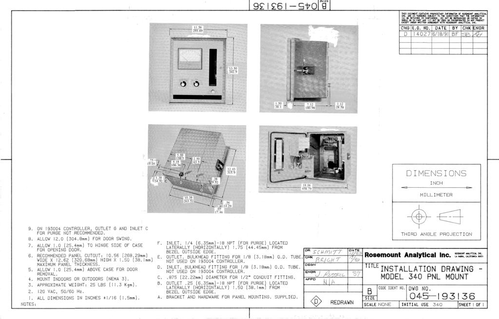
73
74
75
76
77
78
79
80
81
82

83
Rosemount Analytical MODEL 340 TRACE MOISTURE ANALYZER INSTRUCTION MANUAL N
 Rosemount Analytical MODEL 340 TRACE MOISTURE ANALYZER INSTRUCTION MANUAL 081854-N NOTICE The information contained in this document is subject to change without notice. Teflon is a registered trademark
Rosemount Analytical MODEL 7D THERMAL CONDUCTIVITY ANALYZER EXPLOSION PROOF INSTRUCTION MANUAL J1
 Rosemount Analytical MODEL 7D THERMAL CONDUCTIVITY ANALYZER EXPLOSION PROOF INSTRUCTION MANUAL 748221-J1 NOTICE The information contained in this document is subject to change without notice. This manual
Model 755R Oxygen Analyzer
 Instruction Manual Model 755R Oxygen Analyzer http://www.processanalytic.com ESSENTIAL INSTRUCTIONS READ THIS PAGE BEFORE PROCEEDING! Rosemount Analytical designs, manufactures and tests its products to
Rosemount Analytical MODEL 755A OXYGEN ANALYZER INSTRUCTION MANUAL U
 Rosemount Analytical MODEL 755A OXYGEN ANALYZER INSTRUCTION MANUAL 245364-U NOTICE The information contained in this document is subject to change without notice. Teflon is a registered trademark of E.I.
Model ROX Oxygen Analyzers
 Instruction Manual Model ROX Oxygen Analyzers http://www.processanalytic.com ESSENTIAL INSTRUCTIONS READ THIS PAGE BEFORE PROCEEDING! Rosemount Analytical designs, manufactures and tests its products to
HFID Heated Total Hydrocarbon Analyzer Module
 Product Data Sheet PDS 103-685.A01 October, 2003 NGA 2000 HFID Heated Total Hydrocarbon Analyzer Module Heated analyzer designed to operate from 200 F to 400 F Eliminates loss of hydrocarbons due to condensation
RK Hydrogen Sulfide Transmitter Operator s Manual
 65-2331RK Hydrogen Sulfide Transmitter Operator s Manual Part Number: 71-0176RK Revision: B Released: 11/26/14 RKI Instruments, Inc. www.rkiinstruments.com WARNING Read and understand this instruction
RK-02 Multi Point Detector Operator s Manual
 65-2485RK-02 Multi Point Detector Operator s Manual Part Number: 71-0237RK Revision: A Released: 11/26/14 RKI Instruments, Inc. www.rkiinstruments.com WARNING Read and understand this instruction manual
RK Carbon Monoxide Transmitter Operator s Manual
 65-2335RK Carbon Monoxide Transmitter Operator s Manual Part Number: 71-0177RK Revision: 0 Released: 4/12/11 RKI Instruments, Inc. www.rkiinstruments.com WARNING Read and understand this instruction manual
CT-7 Series Toxic Gas Transmitter Operator s Manual
 65-2341 CT-7 Series Toxic Gas Transmitter Operator s Manual Part Number: 71-0424 Revision: P1 Released: 6/8/17 RKI Instruments, Inc. www.rkiinstruments.com WARNING Read and understand this instruction
RK-05 Carbon Monoxide Transmitter Operator s Manual
 65-2432RK-05 Carbon Monoxide Transmitter Operator s Manual Part Number: 71-0113RK Revision: B Released: 11/26/14 www.rkiinstruments.com WARNING Read and understand this instruction manual before operating
RK-05 Carbon Monoxide Detector Operator s Manual
 65-2433RK-05 Carbon Monoxide Detector Operator s Manual Part Number: 71-0189RK Revision: 0 Released: 5/17/11 RKI Instruments, Inc. www.rkiinstruments.com WARNING Read and understand this instruction manual
RK Multi Point Detector Operator s Manual
 65-2480RK Multi Point Detector Operator s Manual Part Number: 71-0198RK Revision: C Released: 11/26/14 RKI Instruments, Inc. www.rkiinstruments.com WARNING Read and understand this instruction manual before
Instruction Manual. CAT 100 & CAT 200 Continuous Analyzer Transmitter Addendum for Hazardous Area Applications. 3 rd Edition 05/2007
 CAT 100 & CAT 200 Continuous Analyzer Transmitter Addendum for Hazardous Area Applications 3 rd Edition www.emersonprocess.com CAT 100 & CAT 200 Addendum for Hazardous Area Applications ESSENTIAL INSTRUCTIONS
RK-05 Combustible Gas Transmitter Operator s Manual
 65-2405RK-05 Combustible Gas Transmitter Operator s Manual Part Number: 71-0180RK Revision: 0 Released: 2/16/11 RKI Instruments, Inc. www.rkiinstruments.com WARNING Read and understand this instruction
Oxygen Analyzer Manual
 Oxygen Analyzer Manual AMI Model 70 AMI, Huntington Beach Contents Preface 1 The AMI story 1 Caution 1 Address 1 Model 70 Oxygen Analyzer 2 Introduction 2 Features: 2 Oxygen sensor: 3 Sensor Warranty:
Models TX-KE and TX-KP Toxic Gas Transmitters
 Models TX-KE and TX-KP Toxic Gas Transmitters Instruction Manual PureAire Monitoring Systems, Inc. 557 Capital Dr. Lake Zurich, IL. 60047 Phone: 847-726-6000 Fax: 847-726-6051 Toll-Free: 888-788-8050 www.pureairemonitoring.com
RK/ RK Carbon Monoxide Detector Operator s Manual
 65-2496RK/65-2499RK Carbon Monoxide Detector Operator s Manual Part Number: 71-0156RK Revision: 0 Released: 2/16/11 www.rkiinstruments.com WARNING Read and understand this instruction manual before operating
MST, INC. MODEL 2002 CARBON MONOXIDE MONITOR OWNER S MANUAL
 MST, INC. MODEL 2002 CARBON MONOXIDE MONITOR OWNER S MANUAL IMPORTANT WARNING WHEN THE CO MONITOR IS CORRECTLY INSTALLED AND MAINTAINED, IT MONITORS THE LEVEL OF CARBON MONOXIDE IN THE RESPIRATORY AIR
Installation Requirements for Models:
 900 & 9100 Series Refrigerators Installation Requirements for Models: 9162 9163 9182 9183 962 963 982 983 WARNING Improper installation, adjustment, alteration, service, or maintenance can cause injury
INSTALLATION, OPERATING & MAINTENANCE INSTRUCTIONS FOR 870 SERIES INDUSTRIAL CONTROL PANELS
 INSTALLATION, OPERATING & MAINTENANCE INSTRUCTIONS FOR 870 SERIES INDUSTRIAL CONTROL PANELS GENERAL INDEECO Industrial Control Panels are designed to provide years of trouble free operation if properly
Model SM100. Aspirated Sampling Module
 Aspirated Sampling Module The information and technical data disclosed in this document may be used and disseminated only for the purposes and to the extent specifically authorized in writing by General
RK CO 2 Transmitter Operator s Manual
 65-2397RK CO 2 Transmitter Operator s Manual Part Number: 71-0185RK Revision: B Released: 7/18/14 RKI Instruments, Inc. www.rkiinstruments.com WARNING Read and understand this instruction manual before
MODEL A-316 CARBON MONOXIDE (CO) MONITOR AND ALARM FOR COMPRESSED AIR TESTING
 MONITOR AND ALARM FOR COMPRESSED AIR TESTING") MODEL A-316 CARBON MONOXIDE (CO) MONITOR AND ALARM FOR COMPRESSED AIR TESTING FOR OPERATION FROM 115 AC POWER Andersen Medical Gas 12 Place Lafitte Madisonville, LA 70447 http://www.themedicalgas.com 1-866-288-3783
MODEL A-316 CARBON MONOXIDE (CO) MONITOR AND ALARM FOR COMPRESSED AIR TESTING FOR OPERATION FROM 115 AC POWER Andersen Medical Gas 12 Place Lafitte Madisonville, LA 70447 http://www.themedicalgas.com 1-866-288-3783
RK Carbon Monoxide Transmitter Operator s Manual
 65-2432RK Carbon Monoxide Transmitter Operator s Manual Part Number: 71-0070RK Revision: P1 Released: July 8, 2001 RKI Instruments, Inc. 1855 Whipple Road Hayward CA 94544 Phone: 800-754-5165 Fax: 510-441-5650
S150 S300 CONSTRUCTION HEATERS. Rev: August 15, 2008 SERVICE AND MAINTENANCE MANUAL No PLEASE RETAIN FOR FUTURE REFERENCE PRODUCTS
 S150 & S300 CONSTRUCTION HEATERS Rev: 2.7.2 August 15, 2008 SERVICE AND MAINTENANCE MANUAL No. 934-6637 PLEASE RETAIN FOR FUTURE REFERENCE PRODUCTS A DIVISION OF HAUL-ALL EQUIPMENT LTD. 4115-18 Avenue
MST, INC. MODEL 2002 CARBON MONOXIDE MONITOR (AMBIENT-TYPE) OWNER S MANUAL
 OWNER S MANUAL") MST, INC. MODEL 2002 CARBON MONOXIDE MONITOR (AMBIENT-TYPE) OWNER S MANUAL IMPORTANT WARNING WHEN THE CO MONITOR IS CORRECTLY INSTALLED AND MAINTAINED, IT MONITORS THE LEVEL OF CARBON MONOXIDE IN ITS SURROUNDINGS..
MST, INC. MODEL 2002 CARBON MONOXIDE MONITOR (AMBIENT-TYPE) OWNER S MANUAL IMPORTANT WARNING WHEN THE CO MONITOR IS CORRECTLY INSTALLED AND MAINTAINED, IT MONITORS THE LEVEL OF CARBON MONOXIDE IN ITS SURROUNDINGS..
Duct and Rough Service Carbon Monoxide Sensor
 Product Identification and Overview Duct and Rough Service Carbon Monoxide Sensor BAPI s Carbon Monoxide Sensor offers enhanced electrochemical sensing with outstanding accuracy at low concentrations.
INSTALLATION, OPERATING & MAINTENANCE INSTRUCTIONS FOR 350 SERIES CIRCULATION HEATERS
 INDEECO Circulation Heaters are designed to provide years of trouble free operation if properly installed and maintained. Please read and follow these instructions for installing and maintaining the heater.
RKA-LEL Sample Draw Combustible Gas Detector
 35-3000RKA-LEL Sample Draw Combustible Gas Detector Specifications Table 1 lists specifications for the sample draw combustible gas detector. Table 1: Specifications Target Gas Input Power Combustible
OPERATION & MAINTENANCE MANUAL
 PO Box 979 Ann Arbor, MI 48106-0979 ISA M OPERATION & MAINTENANCE MANUAL 80003-027 04/27/95 MCN-204, 10/20/98 MCN-285, 11/20/02 Table of Contents 1.0 INTRODUCTION...1 1.1 Unpack... 1 1.2 Check Order...
RK Carbon Monoxide Transmitter Operator s Manual
 65-2434RK Carbon Monoxide Transmitter Operator s Manual Part Number: 71-0061RK Edition: First, Revision C Released: December 2001 65-2434RK CO Transmitter 1 Product Warranty RKI Instruments, Inc., warranties
Rosemount Analytical MODEL 890 UV ANALYZER INSTRUCTION MANUAL A
 Rosemount Analytical MODEL 890 UV ANALYZER INSTRUCTION MANUAL 748460-A NOTICE The information contained in this document is subject to change without notice. Teflon and Viton are registered trademarks
451 Black Forest Road Hull, IA Ph: (712) Fax: (712) TS g/hr Turnkey Ozone Generation System
 Fax: (712) TS g/hr Turnkey Ozone Generation System") 451 Black Forest Road Hull, IA 51239 Ph: (712) 439-6880 Fax: (712) 439-6733 TS-40 40 g/hr Turnkey Ozone Generation System Installation and Operation Manual TS-40 Manual Cautions, Warnings and Hazards
451 Black Forest Road Hull, IA 51239 Ph: (712) 439-6880 Fax: (712) 439-6733 TS-40 40 g/hr Turnkey Ozone Generation System Installation and Operation Manual TS-40 Manual Cautions, Warnings and Hazards
Isco 3700ZR Sampler. Manual Set
 Isco 3700ZR Sampler Manual Set Assembly #60-2744-045 Copyright 2001. All rights reserved, Teledyne Isco Revision D, December 14, 2012 This set of manuals supports the Isco 3700ZR Refrigerated Sampler.
P R O D U C T S P E C I F I C A T I O N MSA Ultima X Series Sensor/Transmitter Specification
 P R O D U C T S P E C I F I C A T I O N MSA Ultima X Series Sensor/Transmitter Specification 1.0 This specification details the attributes and operating characteristics of the MSA Ultima X Series sensors/transmitters.
LABORATORY ULTRA ZERO AIR GENERATOR. ZAC-ULT Series USER MANUAL
 LABORATORY ULTRA ZERO AIR GENERATOR ZAC-ULT Series USER MANUAL 166 Keystone Drive Montgomeryville, PA 18936 Telephone: 215-641-2700 Fax: 215-641-2714 Email: mtgmmville@matheson-trigas.com INT-0261-XX rev
MEGA. cal electronic gas alarm. Installation, Operation, and Maintenance Instructions. Part No Rev. D Pg.
 WARD OXYGEN Installation, Operation, and Maintenance Instructions MEGA medical electronic gas alarm MEGA WARD MEGA medical electronic gas alarm WARD POWER SUPPLY Medical Electronic Gas Alarm OXYGEN SYSTEM
GAS MONITOR Model Model
 Sierra Monitor Corporation 1991 Tarob Court, Milpitas, CA 95035 (408) 262-6611 (800) 727-4377 (408) 262-9042 - Fax E-mail: sierra@sierramonitor.com Web Site: www.sierramonitor.com GAS MONITOR Model 2350-00
RK Combustible Gas Transmitter Operator s Manual
 65-2400RK Combustible Gas Transmitter Operator s Manual Part Number: 71-0060RK Revision: C Released: 1/31/13 www.rkiinstruments.com WARNING Read and understand this instruction manual before operating
Carbon Monoxide Sample-Draw Detector Operator s Manual
 35-3001-04-01 Carbon Monoxide Sample-Draw Detector Operator s Manual Part Number: 71-0395 Revision: 0 Released: 8/4/17 www.rkiinstruments.com WARNING Read and understand this instruction manual before
MiniCO, MiniH 2 S, MiniOX, MiniOX Remote, MiniCl 2. , and MiniClO 2. Responder Detectors Instruction Manual "! WARNING
 MiniCO, MiniH 2 S, MiniOX, MiniOX Remote, MiniCl 2 TM, and MiniClO 2 TM Responder Detectors Instruction Manual "! WARNING THIS MANUAL MUST BE CAREFULLY READ BY ALL INDIVIDUALS WHO HAVE OR WILL HAVE THE
GG-LEL2 COMBUSTIBLE GAS SENSOR. Installation and Operation Manual
 GG-LEL2 COMBUSTIBLE GAS SENSOR Installation and Operation Manual 2 GG-LEL2 Warning Use this product only in the manner described in this manual. If the equipment is used in a manner not specified by Calibration
WILKERSON MODELS DE3, DE4 AND DE5 COMPACT HEATLESS AIR DRYERS
 INSTRUCTION MANUAL FOR WILKERSON MODELS DE3, DE4 AND DE5 COMPACT HEATLESS AIR DRYERS DE3 - DE5 OPERATIONS GENERAL This instruction manual covers the installation, operation, maintenance and troubleshooting
Operation and Maintenance Manual
 Operation and Maintenance Manual GDS-48 Remote Bridge Sensor for Combustible Gases AUTHORIZED DISTRIBUTOR: GasDetectorsUSA.com - Houston, Texas USA sales@gasdetectorsusa.com - 832-615-3588 CAUTION: FOR
GG-CO-EXP CARBON MONOXIDE SENSOR. Installation and Operation Manual
 GG-CO-EXP CARBON MONOXIDE SENSOR Installation and Operation Manual 2 GG-CO-EXP Warning Use this product only in the manner described in this manual. If the equipment is used in a manner not specified by
Safe Operation Manual. Honeywell IQ Force Gas Detector
 Safe Operation Manual Honeywell IQ Force Gas Detector Honeywell Analytics 800-663-4164 403-248-9226 Fax 403-575-3708 03JUN2012 P/N 50105843-047 Version 01 http://www.honeywell.com HONEYWELL IQ Force PERSONAL
Combustible Gas Sample-Draw Detector Operator s Manual
 35-3001-01 Combustible Gas Sample-Draw Detector Operator s Manual Part Number: 71-0282RK Revision: A Released: 8/3/17 www.rkiinstruments.com WARNING Read and understand this instruction manual before operating
Service Manual For model N260 - a 2.4 cu. ft., 2-way refrigerator. For model N a 2.4 cu. ft., 3-way refrigerator.
 Service Manual For model N260 - a 2.4 cu. ft., 2-way refrigerator. For model N260.3 - a 2.4 cu. ft., 3-way refrigerator. NORCOLD, Inc. P.O. Box 4248 Sidney, OH 45365-4248 Part No. 619260A (4-98) Table
Toxic Gas Detection. Model F12. Toxic Gas Detection
 Toxic Gas Detection Model F12 Toxic Gas Detection Smart Sensor Technology The Series F12 Gas Transmitter is an Intrinsically Safe (IS) version of our explosion-proof D12 transmitter. In its standard form,
MODEL 5800A CARBON MONOXIDE (CO) MONITOR AND ALARM SAMPLE-DRAWING TYPE
 MONITOR AND ALARM SAMPLE-DRAWING TYPE") MODEL 5800A CARBON MONOXIDE (CO) MONITOR AND ALARM SAMPLE-DRAWING TYPE 11//07 A153-021500-1 INSTRUCTION MANUAL - MODEL 5800A CO ALARM I INTRODUCTION This MST Model 5800A Carbon Monoxide (CO) Alarm is a
MODEL 5800A CARBON MONOXIDE (CO) MONITOR AND ALARM SAMPLE-DRAWING TYPE 11//07 A153-021500-1 INSTRUCTION MANUAL - MODEL 5800A CO ALARM I INTRODUCTION This MST Model 5800A Carbon Monoxide (CO) Alarm is a
MST, INC. MODEL 2002 OXYGEN MONITOR (AMBIENT-TYPE) OWNER S MANUAL
 OWNER S MANUAL") MST, INC. MODEL 2002 OXYGEN MONITOR (AMBIENT-TYPE) OWNER S MANUAL IMPORTANT WARNING WHEN THE OXYGEN MONITOR IS CORRECTLY INSTALLED AND MAINTAINED, IT MONITORS THE LEVEL OF OXYGEN IN ITS SURROUNDINGS 07/11
MST, INC. MODEL 2002 OXYGEN MONITOR (AMBIENT-TYPE) OWNER S MANUAL IMPORTANT WARNING WHEN THE OXYGEN MONITOR IS CORRECTLY INSTALLED AND MAINTAINED, IT MONITORS THE LEVEL OF OXYGEN IN ITS SURROUNDINGS 07/11
Title: Standard Operating Procedure for Measurement of Total Hydrocarbon Using a Flame Ionization Detection
 Procedure No: SOP-020 Revision No: 1.0 (January 21, 2011) Page No.: 1 of 7 1. INTRODUCTION AND SCOPE To obtain timely data for the purpose of air quality assessment, air quality trend reporting, and to
RK-CH4-4 Combustible Gas Transmitter Operator s Manual
 65-2394RK-CH4-4 Combustible Gas Transmitter Operator s Manual Part Number: 71-0277RK Revision: P1 Released: 4/9/13 RKI Instruments, Inc. www.rkiinstruments.com WARNING Read and understand this instruction
RK-OXY Oxygen Sample-Draw Detector Operator s Manual Part Number: RK Revision: P1 Released: 7/18/02
 35-3000RK-OXY Oxygen Sample-Draw Detector Operator s Manual Part Number: 71-0071RK Revision: P1 Released: 7/18/02 RKI Instruments Inc. 1855 Whipple Road Hayward, CA 94544 PH: 800-754-5165 Fax: 510-441-5650
OG5000 Ozone Generator Model OG5000B-A. User Manual
 OG5000 Ozone Generator Model OG5000B-A Copyright 2017 610-0082-01H DCN7785 Teledyne API 25 September 2017 Contents CONTENTS... 1 FIGURES... 2 TABLES... 2 1. GENERAL PRECAUTIONS... 3 Safety... 5 Safety
M2A Transmitter Operator s Manual
 M2A Transmitter Operator s Manual Part Number: 71-0305RK Revision: F Released: 1/8/18 RKI Instruments, Inc. www.rkiinstruments.com WARNING Read and understand this instruction manual before operating instrument.
GASGUARD H 2-1% Hydrogen Sensor OPERATING & INSTALLATION MANUAL
 GASGUARD H 2-1% Hydrogen Sensor OPERATING & INSTALLATION MANUAL 2 Table of Contents GasGuard H 2-1% General description. 4 Installation.. 4 Locating the sensor. 4 Installation guidelines 5 Wiring.. 6 Operation..
Single Doors FIREGUARD Series Use one Master Unit each door or one 2409 Support unit each door. Pairs of Doors
 Hinge Edge of Door Hinge Edge of Door Wiring Instructions for the Sargent 0 Series FIREGUARD Combination Door Closer-Holder and Releasing Device with Integral Smoke Detector CAUTION: FAILURE TO INSTALL
Combustible Gas/Hydrogen Sulfide Sample-Draw Detector Operator s Manual
 35-3001-07 Combustible Gas/Hydrogen Sulfide Sample-Draw Detector Operator s Manual Part Number: 71-0411 Revision: 0 Released: 8/7/17 www.rkiinstruments.com WARNING Read and understand this instruction
Carbon Dioxide Sample-Draw Detector Operator s Manual
 35-3001-05-03 Carbon Dioxide Sample-Draw Detector Operator s Manual Part Number: 71-0413 Revision: 0 Released: 8/4/17 www.rkiinstruments.com WARNING Read and understand this instruction manual before operating
RK-03 Hydrogen Detector Operator s Manual
 61-1001RK-03 Hydrogen Detector Operator s Manual Part Number: 71-0371 Revision: P1 Released: 5/26/15 www.rkiinstruments.com WARNING Read and understand this instruction manual before operating detector.
Dual Input ph/orp Analyzer
 Instruction Sheet PN 51A-1055pH/rev.I February 2006 Model 1055 SOLU COMP II Dual Input ph/orp Analyzer Model Option 1055-22-32 For additional information, please refer to the Instruction Manuals CD shipped
RK / RK Methane Detector Operator s Manual
 61-1006RK / 61-0192RK Methane Detector Operator s Manual Part Number: 71-0228RK Revision: 0 Released: 10/29/18 www.rkiinstruments.com WARNING Read and understand this instruction manual before operating
MODELS 304GC, 304GCX, 314GC, and 314GCX
 2562109A REV. A1 0317 Printed in U.S.A. MODELS 304GC, 304GCX, 314GC, and 314GCX INSTALLATION AND SERVICE INSTRUCTIONS FOR SELECTONE Limited Warranty This product is subject to and covered by a limited
GASGUARD H2S EXP. Hydrogen Sulfide Sensor OPERATING & INSTALLATION MANUAL
 GASGUARD H2S EXP Hydrogen Sulfide Sensor OPERATING & INSTALLATION MANUAL Operating and Installation Manual Warning Use this product only in the manner described in this manual. If the equipment is used
Combustible Gas/Carbon Monoxide Sample-Draw Detector Operator s Manual
 35-3001-08 Combustible Gas/Carbon Monoxide Sample-Draw Detector Operator s Manual Part Number: 71-0396 Revision: 0 Released: 8/7/17 www.rkiinstruments.com WARNING Read and understand this instruction manual
Intrinsically Safe Pressure Transmitters for installation in hazardous locations Models IS-20-S, IS-21-S, IS-20-F, IS-21-F WIKA Datasheet IS-20
 Electronic Pressure Measurement Intrinsically Safe Pressure Transmitters for installation in hazardous locations Models IS-20-S, IS-21-S, IS-20-F, IS-21-F WIKA Datasheet IS-20 Applications Chemical, Petrochemical
TOXIC GAS AND OXYGEN DETECTOR DTX 420 INSTALLATION, OPERATING AND MAINTENANCE INSTRUCTIONS DTX420_MAN01_EN_V1R2
 TOXIC GAS AND OXYGEN DETECTOR INSTALLATION, OPERATING AND MAINTENANCE INSTRUCTIONS DTX420_MAN01_EN_V1R2 1 Introduction These instructions must be read carefully by any person who has or will have the responsibility
For technical questions, contact: Grace Engineered Products Inc./ 5001 Tremont Ave, Davenport, IA /
 For technical questions, contact: Grace Engineered Products Inc./ 5001 Tremont Ave, Davenport, IA 52807 / 800.280.9517 563.386.9639 (Fax) INSTALLATION AND OPERATING INSTRUCTIONS R-3W2 UL APPROVED FOR:
DESIGN MANUAL MODEL GIR900 INFRARED COMBUSTIBLE GAS SENSOR
 DESIGN MANUAL MODEL GIR900 INFRARED COMBUSTIBLE GAS SENSOR 70086 The information in this doucment is applicable to sensors built in September, 2008 or later (Firmware 3.0) The information and technical
RKA-03 Sample-Draw Detector Head
 35-3010RKA-03 Sample-Draw Detector Head Part Number: 71-0134RK Revision: E Released: 6/5/17 rkiinstruments.com WARNING Read and understand this instruction manual before operating detector. Improper use
PUV, PIR and PFO Series BROCHURE
 PUV, PIR and PFO Series BROCHURE JUNHO 2013 ABB Multiwave TM process photometers PUV3402, PIR3502 and PFO3372 Measure vapor and liquid samples in IR, NIR, UV and VIS regions Process photometers PUV3402,
M2 Transmitter Operator s Manual
 M2 Transmitter Operator s Manual Part Number: 71-0107RK Revision: D Released: 10/7/10 RKI Instruments, Inc. www.rkiinstruments.com WARNING Read and understand this instruction manual before operating instrument.
Advance Optima Continuous Gas Analyzers AO2060-Caldos15, -Caldos17, -Magnos106, -Uras14 Category 2G Analyzer Modules
 Advance Optima Continuous Gas Analyzers AO2060-Caldos15, -Caldos17, -Magnos106, -Uras14 Category 2G Analyzer Modules Operator s Manual 42/24-12 EN Rev. 4 Contents Page Preface 4 Safety Information General
Rosemount 372. HF Resistant ph sensor. Quick Start Guide LIQ-QSG-372 Rev. C June 2017
 Rosemount 372 HF Resistant ph sensor Quick Start Guide LIQ-QSG-372 Rev. C June 2017 hasgkas Essential Instructions Read this page before proceeding! Emerson designs, manufactures and tests its products
Hydrogen Generator Model HPNM 1. Instruction manual. 166 Keystone Drive Montgomeryville, PA Phone: Fax:
 Hydrogen Generator Model HPNM 1 Instruction manual 166 Keystone Drive Montgomeryville, PA 18936 Phone: 215-641-2700 Fax: 215-641-2714 Introduction Index INDEX... 2 INTRODUCTION... 3 SCOPE OF THE MANUAL...
Operating Instructions
 Operating Instructions Sieger Type 705 CO Sensor and Transmitter for Electrochemical Cells UL Certified 00705A1731 HELPING TO MAKE A SAFER WORLD Ensure that you read and understand these Operating Instructions
Dual Input ph/conductivity Analyzer
 Instruction Sheet PN 51A-1055pHC/rev.I January 2006 Model 1055 SOLU COMP II Dual Input ph/conductivity Analyzer Model Option 1055-22-30 For additional information, please refer to the Instruction Manuals
Dual Input Toroidal Analyzer
 Instruction Sheet PN 51A-1055T/rev.H February 2006 Model 1055 SOLU COMP II Dual Input Toroidal Analyzer Model Option 1055-21-31 For additional information, please refer to the Instruction Manuals CD shipped
INSTALLATION, OPERATION INSTRUCTIONS FOR FLOW SWITCHES 62-9FS & FS
 THERMAL INSTRUMENT Co. 217 Sterner Mill Road, Trevose, PA 19053 Telephone No. (215) 355-8400 Fax No. (215) 355-1789 Email: office@thermalinstrument.com INSTALLATION, OPERATION INSTRUCTIONS FOR FLOW SWITCHES
RK/ RK Oxygen Detector Operator s Manual
 65-2494RK/65-2497RK Oxygen Detector Operator s Manual Part Number: 71-0179RK Revision: 0 Released: 2/16/11 www.rkiinstruments.com WARNING Read and understand this instruction manual before operating detector.
Dissolved Oxygen Sensors
 Instruction Sheet PN 51A-HxDO/rev.E July 2005 Models Hx438 and Gx448 Dissolved Oxygen Sensors For additional information, please refer to the Instruction Manuals CD shipped with this product, or visit
Freightliner Refrigerator Troubleshooting Guide For (TJ18F) (TJ22F) (TJ18FP3)
 (TJ22F) (TJ18FP3)") www.dometic.com Freightliner Refrigerator Troubleshooting Guide For Before initiating troubleshooting, the following equipment is recommended: Multimeter, 20 gauge (min) wires to use as jumpers, and 12Vdc
www.dometic.com Freightliner Refrigerator Troubleshooting Guide For Before initiating troubleshooting, the following equipment is recommended: Multimeter, 20 gauge (min) wires to use as jumpers, and 12Vdc
Operator: Save these instructions for future use!
 50A66-743 Integrated Furnace Control Operator: Save these instructions for future use! FAILURE TO READ AND FOLLOW ALL INSTRUCTIONS CAREFULLY BEFORE INSTALLING OR OPERATING THIS CONTROL COULD CAUSE PERSONAL
RAM 50 Series Operation Manual
 RAM 50 Series Operation Manual Worldwide Manufacturer of Gas Detection Solutions Table of Contents Page Introduction... 3 Detection Principle... 3 Overview... 3 Description... 4 Switches... 4 Indicators...
Air Check O 2 Sample Draw Monitor
 Air Check O 2 Sample Draw Monitor Instruction Manual PureAire Monitoring Systems, Inc. 557 Capital Drive Lake Zurich, Illinois 60047 Phone: 847-726-6000 Fax: 847-726-6051 Toll-Free: 888-788-8050 pureairemonitoring.com
MODELS ASHP, ASHH, ASUP, and ASUH
 2562229A REV. A 1210 Printed in U.S.A. MODELS ASHP, ASHH, ASUP, and ASUH INSTALLATION AND SERVICE INSTRUCTIONS blank page INSTALLATION AND SERVICE INSTRUCTIONS FOR MODELS ASHP, ASHH, ASUP, AND ASUH SAFETY
ANALOX 5001 Carbon Dioxide Monitor. User Manual ANALOX Analox 5001 Carbon Dioxide Monitor User Manual
 ANALOX 5001 ANALOX 5001 Carbon Dioxide Monitor User Manual Analox Sensor Technology Ltd 15 Ellerbeck Court, Stokesley Business Park North Yorkshire, TS9 5PT T: +44 (0)1642 711400 F: +44 (0)1642 713900
AUTOMOTIVE REFRIGERANT ANALYZER OPERATION MANUAL. Analyzer Part Number: 68941
 AUTOMOTIVE REFRIGERANT ANALYZER OPERATION MANUAL Analyzer Part Number: 68941 Table of Contents FOR YOUR SAFETY:... 3 IDENTIFIER WARNINGS/GENERAL CAUTIONS... 3 WELCOME... 5 1 INTRODUCTION AND OVERVIEW...
RK Transmitter Technical Notice
 65-2450RK Transmitter Technical Notice Although this Operator s Manual was written for the 65-2400RK combustible gas LEL transmitter, the operational instructions are the same for the 65-2450RK hydrogen
RecoverX-CAR Contaminated Automotive Refrigerant Recovery System Operation and Maintenance Manual
 RecoverX-CAR Contaminated Automotive Refrigerant Recovery System Operation and Maintenance Manual (English) Table of Contents Page General Safety Instructions...2 System Overview...3 RecoverX-CAR Operation
Beacon 800 Gas Monitor Operator s Manual
 Beacon 800 Gas Monitor Operator s Manual Part Number: 71-0037RK Revision: F Released: 4/18/17 www.rkiinstruments.com Product Warranty RKI Instruments, Inc. warrants gas alarm equipment sold by us to be
OPERATING INSTRUCTIONS FOR
 OPERATING INSTRUCTIONS FOR Model 3190Z Trace Oxygen Analyzer P/N M3190Z 6/09/09 DANGER Toxic gases and or flammable liquids may be present in this monitoring system. Personal protective equipment may be
Ductless Split Air Conditioner
 Ductless Split Air Conditioner Installation Manual Indoor HSU09VHG(DB)-W HSU12VHG(DB)-W HSU18VHH(DB)-W HSU24VHG(DB)-W Outdoor HSU09VHG(DB)-G HSU12VHG(DB)-G HSU18VHH(DB)-G HSU24VHG(DB)-G Table of Contents
Wiring Instructions. Single Doors 99 Checkmate Series Use one or Master Unit each door or one or Support unit each door
 CAUTION Hinge Edge of Door Wiring Instructions Checkmate Series with Single Point Hold-Open Combination Door Closer-Holder and Releasing Device with or without Integral Smoke Detector INSTALLER: LEAVE
Mustang Vaporizer. Installation, Operation & Maintenance MV
 Mustang Vaporizer Installation, Operation & Maintenance MV TABLE OF CONTENTS Safety Warnings 3 Product Features 4 Technical Specifications 5 Product Dimensions & Parts 6 Electrical Wiring Diagrams 8 Installation
OPERATING INSTRUCTIONS MANUAL (Please retain for future reference) F-1500T DUAL FUEL CONSTRUCTION HEATER
 F-1500T DUAL FUEL CONSTRUCTION HEATER") OPERATING INSTRUCTIONS MANUAL (Please retain for future reference) For F-1500T DUAL FUEL CONSTRUCTION HEATER CERTIFIED FOR USE IN CANADA AND U.S.A. As per Standard ANSI Z83.7 2000/ CSA 2.14 2000 Gas Fired
OPERATING INSTRUCTIONS MANUAL (Please retain for future reference) For F-1500T DUAL FUEL CONSTRUCTION HEATER CERTIFIED FOR USE IN CANADA AND U.S.A. As per Standard ANSI Z83.7 2000/ CSA 2.14 2000 Gas Fired
METROTEC Systeme zur Messung und Regelung von Sauerstoff
 Systeme zur Messung und Regelung von Sauerstoff U15-DIGITAL Oxygen Measuring and Control Device U15 Series Measuring module *** Version 1.1 *** Our management system is certified according to DIN EN ISO
PORTABLE DEW POINT MONITOR
 PORTABLE DEW POINT MONITOR MODEL 8072, 8072-230VAC (units made after 2002) Table of Contents INTRODUCTION... 2 SPECIFICATIONS:... 2 OPERATION... 3 Dryer Output Sampling... 3 Hopper Output Sampling... 3