CVX-300 CVX-300 -P Excimer Laser System
|
|
|
- Lorraine Heath
- 6 years ago
- Views:
Transcription


1 CVX-300 CVX-300 -P Excimer Laser System Operator's Manual Version 22 08May12 1/
2 2012 THE SPECTRANETICS CORPORATION. ALL RIGHTS RESERVED. The documentation contained herein is confidential and proprietary. This documentation may not be copied, reproduced, disclosed, transferred, or reduced to any form, including electronic medium or machine-readable form. This documentation may not be transmitted or publicly performed by any means, electronic or otherwise, without the written consent of The Spectranetics Corporation. The documentation contains valuable trade secrets and proprietary information and is protected by federal copyright laws. Unauthorized use of the documentation can result in civil damages and criminal prosecution. MANUFACTURED UNDER ONE OR MORE OF THE FOLLOWING PATENTS: USP , , , , , , , AND OTHER PATENTS PENDING. 08May12 2/56
3 Preface The CVX-300 is an excimer laser system approved for use in minimally invasive interventional procedures within the cardiovascular system, and for the removal of problematic pacemaker and defibrillator cardiac leads. The CVX-300 produces pulsed excimer radiation which is delivered to the target site with proprietary fiber optic catheter technology, or other approved instruments or accessories, to complete the system. Notice THE CVX-300 CONTAINS NO USER SERVICEABLE PARTS OR ASSEMBLIES. SERVICE OF THE SPECTRANETICS CVX-300 LASER SYSTEM MUST BE PERFORMED ONLY BY A SPECTRANETICS CERTIFIED FIELD SERVICE ENGINEER IN ORDER TO AVOID RISKS TO INDIVIDUALS, CUSTOMERS AND/OR PATIENTS. SERVICE OF THE SPECTRANTICS CVX-300 REQUIRES SPECIAL TOOLS, EQUIPMENT AND/OR GASES, SOME OF WHICH MAY NOT BE COMMERCIALLY AVAILABLE, OR MAY ONLY BE AVAILABLE TO OR FROM THE SPECTRANETICS CORPORATION. SPECTRANETICS ASSUMES NO RESPONSIBILITY OR LIABILITY FOR ANY SERVICE PROVIDED BY NON-CERTIFIED REPRESENTATIVES. SERVICE PERFORMED BY ANYONE OTHER THAN A SPECTRANETICS CERTIFIED FIELD SERVICE ENGINEER VOIDS ALL WARRANTIES (IF ANY) TO THE LASER SYSTEM AND/OR THE DISPOSABLE LASER CATHETER DELIVERY DEVICES. SPECTRANETICS RESERVES THE RIGHT TO REFUSE TO SELL PRODUCTS OR SERVICES TO ANY CUSTOMER NOT IN COMPLIANCE WITH MANUFACTURERS RECOMMENDED SERVICE REQUIREMENTS. 08May12 3/56
4 Contents Warranty... 6 Warnings and Responsibility... 7 Specifications Safety Precautions Nominal Ocular Hazard Distance (NOHD) EMC Precautions Stowable Control Panel / Energy Detector Stowable Energy Detector CVX-300-P Components Control Panel Energy Detector Catheter Connector Front Storage Compartment Footswitch (IPX8 rated) Emergency Button Footswitch Connector Interlock Plug Potential Equalization (PE) Power Connector & Power Cord Strain Relief Clip Main Circuit Breaker CVX-300-P Labeling CVX-300 Labeling CVX-300 Markings Control Buttons Calibrate Fluence Pulses Delivered Read Energy Ready: Reset: Standby: Keyswitch: Treatment Time: Reset and Standby: Reset and Treatment Time: Advisory, Indicator and Status Lights Aim Fiber Energy and Millijoules Calibrate Button Calibrate Light Cal OK Fluence and mj/mm Footswitch Lasing Min-Sec Power Error Pulses Rate and Pulses/Second May12 4/56
5 Ready Service Standby Testing Warm-up Operational Modes Setup Mode Testing Mode Warm-up Mode Standby Mode Calibrate Mode Standby Mode (Returning from Calibrate Mode) Standby Mode (Returning from Ready Mode) Ready Mode Power Down Fault Codes Maintenance Verification of Calibration Troubleshooting Glossary May12 5/56
6 Warranty The Spectranetics Corporation ( Spectranetics ) warrants that the CVX-300 Excimer Laser ( Laser ) will meet the written specifications for the period described in the agreement between Spectranetics and the entity acquiring the Laser ( Customer ). This warranty will become immediately void in the event that any of the following conditions are not met or cease to be true: (i) The Laser must be installed by a Spectranetics Certified Field Service Engineer; (ii) The Laser must be operated and stored in accordance with the Operator's Manual; (iii) All required and recommended maintenance must be performed on time by Spectranetics Certified Field Service Engineers using authorized parts, components, and gases; (iv) The Laser must be kept in the proper operating environment and site requirements; and (v) The Laser must be operated by trained personnel according to approved clinical guidelines using authorized disposable devices. Spectranetics sole obligation under this warranty shall be to provide all parts and labor required to cause the Laser to operate in accordance with the specifications during the warranty period. Spectranetics will perform all warranty service and repairs during the normal business hours of 8:00 am to 5:00 pm at Customer s facility, Monday through Friday, excluding holidays. Customer is responsible for assuring that the Laser is accessible to Certified Field Service Engineers at the scheduled time. Customer will pay Spectranetics at its standard billing rates for: Warranty repairs requested outside of normal business hours; waiting time if the Laser is not available for scheduled maintenance; service made necessary as a result of Customer s failure to follow the requirements in the Operator s Manual; or service that is required due to any damage to the Laser from outside causes. This warranty extends only to the entity that acquires the Laser from Spectranetics and will not extend to any successor of that entity. Spectranetics makes no other warranties, expressed or implied. Spectranetics specifically disclaims any implied warranty of merchantability or fitness for a particular purpose. In no event will Spectranetics be liable for any indirect, special, incidental, punitive, or consequential damages, including, but not limited to, loss of profits and/or loss of business, arising out of or resulting from use of the Laser or its failure to meet the terms of this warranty, even if Spectranetics has been advised of the possibility of such damages. This limited warranty covers only the Laser. Information on Spectranetics warranty relating to disposable items used with the Laser can be found in the documentation relating to those products. 08May12 6/56
7 Warnings and Responsibility IMPORTANT Read the Operator's Manual thoroughly before operating the Excimer Laser System CVX-300. Pay particular attention to the NOTES, CAUTIONS, and WARNINGS throughout this manual to ensure safe operating conditions at all times. Also refer to the Instructions for Use which accompanies Spectranetics fiber optic catheters. Indications and contraindications are included in individual instructions for use for the CVX-300 disposables. WARNING The CVX-300 is a Class III medical device which contains a Class IV laser that produces an invisible beam of high-energy ultraviolet radiation. Improper use of the CVX-300 could result in serious personal injury. Observe all safety precautions for use of Class IV laser equipment. WARNING The CVX-300 contains high voltages which are potentially lethal. To avoid electrical shock, do not open the CVX-300 cabinet. Internal maintenance must be performed solely by a Spectranetics Certified Field Service Engineer. WARNING Laser system is not intended to be used during a defibrillation event. DANGER Possible explosion hazard if used in the presence of flammable anesthetics. 08May12 7/56
8 WARNING Skin exposure to excimer radiation should be avoided. WARNING Move the Excimer Laser System carefully, and avoid jarring or sudden impacts. Disconnect and store the footswitch before moving the laser system. Do not run over power cables with the system. Depress the brake bar to lock the wheels when the Excimer Laser System is positioned for use. Lift up on the brake bar to release wheels. CAUTION Use of buttons or adjustments or performance of procedures other than those specified herein may result in hazardous radiation exposure. WARNING Use only fibers and catheters approved by Spectranetics in the CVX-300 system. The Spectranetics laser fiber optic catheters are supplied sterile. Sterility is guaranteed only if the package is unopened and undamaged. WARNING Use care when handling the fiber optic catheter to ensure the distal or proximal fibers are not chipped or scratched. 08May12 8/56
9 NOTICE WARNING Bypassing the warm-up period if the system has been off for longer than 30 seconds may damage internal components and render the CVX-300 Excimer Laser System inoperable. The CVX-300 is intended for use only by licensed physicians. All persons who operate and service this equipment must be properly trained. NOTICE CAUTION The CVX-300 is designed for continuous operation with intermittent loading. In procedures which exceed 50,000 laser pulses, the CVX-300 must be allowed to idle in Standby Mode for a minimum of one (1) hour. The CVX-300 contains a gas mixture that is 0.05% HCl, a respiratory irritant. To avoid injury, only a trained and certified Spectranetics Field Service Engineer should handle the laser gas. CAUTION Federal Law restricts this device to the sale or on the order of a physician. RESPONSIBILITY Spectranetics is not responsible for injury or damage resulting from improper use of the CVX-300 equipment. If there is any doubt concerning the use of the CVX- 300 or the Operator's Manual, contact Spectranetics immediately for assistance. CUSTOMER understands that the Equipment is manufactured with substances that are considered hazardous to the environment and cannot be disposed of directly. In the unlikely event that CUSTOMER wishes to remove the Equipment from service, they may elect to return the system (at their expense) to SPECTRANETICS. Once the Equipment is received, Spectranetics will bear the cost of properly disposing of and/or recycling the raw components according to law. 08May12 9/56
10 Specifications The excimer laser is a pulsed laser with the following nominal specifications. Active Medium XeCl Wavelength 308 nm Catheter Output Fluence* mj/mm 2 Repetition Rate Range* Hz Pulse Width ns, FWHM Weight 650 lbs / 295 kg Length 49 in / 125 cm Height 35 in / 89 cm - unit 7-9 in / cm - control panel Width 25 in / 62 cm (All Dimensions Approximate) Power Requirements V ~ - Single Phase 50/60Hz 16 Amp Environmental Specifications - Operating temperature: 12 C to 30 C (54 F to 86 F) - Storage temperature: 0 C to 60 C (32 F to 140 F) - Operating humidity: 5 to 95% relative humidity, non-condensing - Storage humidity: 5 to 95% relative humidity, non-condensing System footswitch is IPX8 rated. Accessories: power cord, footswitch, interlock plug, safety glasses, and Spectranetics approved fiber optic catheters. Environment: Avoid exposing the laser system to extreme temperatures (below 32 F or 0 C, above 140 F or 60 C). * dependant on fiber optic catheter in use and the CVX-300 software installed; see the Instructions for Use documentation supplied with each fiber optic catheter for specific information 08May12 10/56
11 Safety Precautions 1. The laser must be operated only by trained personnel. 2. Establish a controlled-access laser operating area to limit access to persons instructed in the safe operation of lasers. 3. Post "LASER IN OPERATION" warning signs at all entries to the laser operating area. 4. Persons in the laser operating area including doctors, nurses, observers and the patient must wear the appropriate protective eyewear and protective gloves. Protective eyewear of 5 or greater at a 308 nanometer (nm) wavelength must be worn when operating the laser system. The laser safety glasses must state the OD rating and wavelength on the lens or on the side shields. Spectranetics offers safety glasses that may be purchased by calling Customer Service. Sources of information about eye protection include: Rockwell Laser Institute (rli.com) and Ultra-Violet Products (uvex.com). 5. Never look directly into the laser beam. 6. Avoid uncontrolled reflections of the laser beam. 7. Skin exposure to excimer laser radiation should be avoided. 8. Do not allow direct or reflected laser radiation to go beyond the laser operating area. 9. When not in use, the laser system should be protected against unauthorized use by removing the key. 08May12 11/56
12 Nominal Ocular Hazard Distance (NOHD) The nominal ocular hazard distance (NOHD) is defined by the American National Standard (ANSI ) Z as the distance along the axis of the unobstructed beam from a laser, fiber end, or connector to the human eye beyond which the irradiance or radiant exposure is not expected to exceed the applicable maximum permissible exposure (MPE) limits. All laser energy produced by the CVX-300 Excimer Laser System, when operated in accordance with this manual, is enclosed within the CVX-300, the Spectranetics Fiber Optic Device or within the body except during the calibration of the fiber optic device (refer to the CVX-300 Excimer Laser System Operating Instructions and precautions in this manual). During these short calibration periods, the energy output from the laser is not contained and the operator should be aware of the NOHD from the tip of the fiber. A 2.5mm fiber optic device emits the highest amount of energy during calibration. The Fiber NOHD was calculated with the system in the Normal Operating Mode during Calibration utilizing the following values; Exposure time 20 seconds Energy at tip of catheter 76.5mJ Fiber Tip Diameter 2.5mm Repetition Rate (calibration) 25 Hz Numerical Aperture of the fiber optic 0.22 Wavelength 308nM Pulse Width 135nS Repetitively Pulsed Yes Using the ANSI Z136.1 standard, the fiber NOHD can be calculated as 1.35 meters (53.1 inches) from the distal tip of the 2.5mm Reference Catheter device during calibration. Always wear the appropriate laser safety glasses when using this equipment and follow all safety precautions as outlined within this manual. 08May12 12/56
13 EMC Precautions Special precautions are required regarding the Electromagnetic Compatibility (EMC) of the CVX-300. The CVX-300 needs to be installed and put into service according the EMC information provided in this manual. Portable and Mobile Radio Frequency (RF) communications equipment can affect any medical electrical equipment including the CVX-300. Only cables and accessories provided by Spectranetics may be used with the CVX-300. The use of any other cable or accessories may have an adverse effect on the Electromagnetic Compatibility of the CVX-300 such as increased emissions or decreased immunity. The CVX-300 should not be used adjacent to or stacked with other equipment. Should use adjacent to other equipment become necessary, the CVX-300 should be observed to verify normal operation in that configuration. Table 201 (EN ) Guidance and Manufacturer s Declaration- Electromagnetic Emissions The CVX-300 is intended for use in the electromagnetic environment specified below. The customer or the user of the CVX-300 should assure that it is used in such an environment. Emissions Test Compliance Electromagnetic environment - guidance The CVX-300 uses RF energy only for its RF emissions CISPR 11 RF emissions CISPR 11 Harmonic Emissions IEC Voltage Fluctuations/ flicker emissions IEC Group 1 Class A Class A Complies internal function. Therefore, its RF emissions are very low and are not likely to cause any interference in nearby electronic equipment. The CVX-300 is suitable for use in all establishments other than domestic and those directly connected to the public low-voltage power supply network that supplies buildings used for domestic purposes. 08May12 13/56
14 Table 202 (EN ) Guidance and Manufacturer s Declaration- Electromagnetic Immunity The CVX-300 is intended for use in the electromagnetic environment specified below. The customer or the user of the CVX-300 should assure that it is used in such an environment. Immunity Test Electrostatic Discharge (ESD) IEC Electrical Fast Transient/Burst IEC Voltage Dips, short interruptions and voltage variations on power supply input lines. IEC Power Frequency (50/60Hz) magnetic field IEC IEC Test Level + 6 kv contact + 8 kv air + 2 kv for power supply lines +1 kv for input/output lines <5% U T (>95% dip in U T for 0,5 cycle 40% U T (60% dip in U T) for 5 cycles 70% U T (30% dip in U T) for 25 cycles <5% U T (>95% dip in U T) for 5 sec. Compliance Level + 6 kv contact + 8 kv air + 2 kv for power supply lines +1 kv for input/output lines 3 A/m 3 A/m 100% dip for 0.5 cycles 60% dip for 5 cycles 30% dip for 25 cycles 100% dip for 5 seconds Electromagnetic environment- guidance Floors should be wood, concrete or ceramic tile. If floors are covered with synthetic material, the relative humidity should be at least 30%. Mains power quality should be that of a typical commercial or hospital environment. Mains power quality should be that of a typical commercial of hospital environment. If the user of the CVX-300 requires continued operation during power mains interruptions, it is recommended that the CVX-300 be powered from an uninterruptible power supply or a battery. Power frequency magnetic fields should be at levels characteristic of a typical location in a typical commercial or hospital environment. NOTE: U T is the ac mains voltage prior to application of the test level. 08May12 14/56

15 Table 204 (EN ) Guidance and manufacturer s declaration Electromagnetic Immunity The CVX-300 is intended for use in the electromagnetic environment specified below. The customer or the user of the CVX-300 should assure that it is used in such an environment. Immunity Test IEC test level Compliance Level Electromagnetic environment- guidance Portable and mobile RF communications equipment should be used no closer to any part of the CVX-300 including cables, than the recommended separation distance calculated from the equation applicable to the frequency of the transmitter. Recommended separation distance d = (3.5/3) P d = (3.5/3) P 80 MHz to 800 MHZ Conducted RF IEC Radiated RF IEC V rms 150 khz to 80 MHz 3 V/m 80 MHZ to 2.5 GHz 3 V rms 3 V/m d = (7/3) P 800 MHz to 2.5 GHz Where P is the maximum output power rating of the transmitter in watts (W) according to the transmitter manufacturer and d is the recommended separation distance in meters (m). Field strengths from fixed RF transmitters, as determined by an electromagnetic site survey, a should be less than the compliance level in each frequency range b Interference may occur in the vicinity of equipment marked with the following symbol. NOTE 1 At 80 MHz and 800 MHz, the higher frequency range applies. NOTE 2 These guidelines may not apply in all situations. Electromagnetic propagation is affected by absorption and reflection from structures, objects and people. a Field strengths from fixed transmitters, such as base stations for radio (cellular/cordless) telephones and land mobile radios, amateur radios, AM and FM radio broadcast and TV broadcast cannot be predicted theoretically with accuracy. To assess the electromagnetic environment due to fixed RF transmitters, an electromagnetic site survey should be considered. If the measured field strength in the location in which the CVX-300 is used exceeds the applicable RF compliance level above, the CVX-300 should be observed to verify normal operation. If abnormal performance is observed, additional measures may be necessary, such as reorienting or relocating the CVX-300. b Over the frequency range 150 khz to 80 MHz, field strengths should be less than 3 V/m 08May12 15/56
16 Table 206 (EN ) Recommended separation distances between portable and mobile RF communications equipment and the CVX-300 The CVX-300 is intended for use in an electromagnetic environment in which radiated RF disturbances are controlled. The customer or the user of the CVX- 300 can help prevent electromagnetic interference by maintaining a minimum distance between portable and mobile RF communications equipment (transmitters) and the CVX-300 as recommended below, according to the maximum output power of the communications equipment. Rated maximum output power of transmitter W Separation distance according to frequency of transmitter m 150 khz to 80 MHz 80 MHz to 800 MHz 800 MHz to 2,5 GHz 0, , For transmitters rated at a maximum output power not listed above, the recommended separation distance d in meters (m) can be estimated using the equation applicable to the frequency of the transmitter, where P is the maximum output power rating of the transmitter in watts (W) according to the transmitter manufacturer. NOTE 1. At 80 MHz and 800 MHz, the separation distance for the higher frequency range applies. NOTE 2. These guidelines may not apply in all situations. Electromagnetic propagation is affected by absorption and reflection from structures, objects and people. 08May12 16/56


17 Stowable Control Panel / Energy Detector Some CVX-300 Excimer Laser Systems have a control panel and an energy detector that can be stowed when not in use. This section will describe how these features are used. Stowable Control Panel When the laser system is not in use, the control panel may be folded flat. To raise the control panel, lift up on the handle. When the control panel is raised, it may be rotated 90 left or right for easy access. NOTICE The control panel may only be stowed when the panel is rotated to face the front of the unit. Do not attempt to rotate the control panel beyond its stops. When stowing the control panel, keep fingers and hands out of the way. 08May12 17/56


18 Stowable Energy Detector The Energy Detector is located to the left of the laser/catheter coupler. The Energy Detector is used to calibrate fiber optic catheters prior to use, and must be pulled up into position to facilitate system calibration. Open Protective Cover Extend the Energy Detector to the fully up position Return the Energy Detector to the storage position by pushing it back into the unit and closing the protective cover. Push Energy Detector back into the unit and close the Protective Cover NOTICE At no time should the energy detector or its mounting pole be used in an attempt to move the CVX-300. As with all CVX-300 units, it is necessary to keep the area around the Catheter Connector, Energy Detector, and Control Panel clean, dry and free of contaminants. 08May12 18/56
19 CVX-300-P Components 1. Control Panel 2. Energy Detector 3. Catheter Connector 4. Front Storage Compartment 5. Footswitch (IPX8 rated) 6. Emergency Button 7. Footswitch Connector 8. Interlock Plug 9. Potential Equalization (PE) (Optional PE cable provided based on destination country) 10. Power Connector & Power Cord Strain Relief Clip 11. Main Circuit Breaker 08May12 19/56

 5 08May12")
20 CVX-300-P Labeling AIM CATHETER AT CENTER OF DETECTOR NEVER TOUCH DETECTOR SURFACE WITH CATHETER TIP 4 (Operating Instructions) 5 08May12 20/56
")
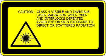
21 6 7 (Laser Radiation) 8 (Non-Ionizing Radiation) 9 08May12 21/56

 (WEEE) 15")
22 10 (Robert A. Golobic Memorial Label Spectranetics Founder) (Label on Remanufactured CVX-300 Only) (WEEE) (Emergency Stop) 08May12 22/56
 2")


")
23 CVX-300 Labeling 1 (Operating Instructions) 2 3 AIM CATHETER AT CENTER OF DETECTOR NEVER TOUCH DETECTOR SURFACE WITH CATHETER TIP 5 4 (Emergency Stop) (Laser Radiation) (Non-Ionizing Radiation) 08May12 23/56
 15 (Label on")
24 10 11 (WEEE) (Robert A. Golobic Memorial Label Spectranetics Founder) 15 (Label on Remanufactured CVX-300 Only) 08May12 24/56
25 CVX-300 Markings Outside: Equipotentiality FOOTSWITCH Footswitch Connector MAINS (16A) (US/CANADA/EU) Main Circuit Breaker Laser Radiation! Warning, Danger, Caution Follow Operating Instructions WEEE (Waste from Electrical and Electronic Equipment) Type CF Emergency Stop 08May12 25/56
26 Inside: Protective Earth (ground) Dangerous Voltage Non-Ionizing Radiation 08May12 26/56
27 Control Buttons Calibrate: Depressing the Calibrate button places the Excimer Laser System in Calibrate mode. The Calibrate button is illuminated. Fluence: The Fluence button adjusts the output energy of the Excimer Laser System. The fluence value is increased or decreased by depressing the appropriate Fluence button. The current fluence value is visible in the display window and the mj/mm 2 indicator light is illuminated. A brief press of either the increase or decrease Fluence button while in other operating modes shows the current fluence value. Depressing either the increase or decrease Fluence buttons for one second or longer changes the fluence value accordingly. Pulses Delivered: Depressing the Pulses Delivered button enables the total number of pulses during a procedure to be visible in the display window. Rate: The Rate button adjusts the pulse repetition rate of the Excimer Laser System. The rate is increased or decreased by depressing the appropriate Rate button. The repetition rate is visible in the display window and the Pulses/Second indicator light is illuminated. A brief press of either the increase or decrease Rate button while in other operating modes shows the current repetition rate. Depressing either the increase or decrease Rate button for one second or longer changes the repetition rate accordingly. Read Energy: Depressing the Read Energy button enables the fiber output energy read by the calibration detector to be visible in the display window. The Read Energy button will be illuminated. 08May12 27/56
28 Ready: Depressing the Ready button places the Excimer Laser System in Ready mode. If the Excimer Laser System has not been calibrated, the Ready button is not active. Reset: The Reset button is used in combination with the Standby button, Pulses Delivered and Treatment Time buttons. Standby: If the system is in either Ready or Calibrate mode, depressing the Standby buttons places the Excimer Laser System in Standby mode. The Standby button and the green status light are illuminated. Keyswitch: The keyswitch is the power control for the Excimer Laser System. In case of emergency, the Excimer Laser System can be powered down by depressing the Emergency Shutoff located on the back panel. Caution should be taken not to activate the Emergency Button accidentally. To reactivate the system, rotate the Emergency Shutoff clockwise until it ascends and turn the keyswitch to the OFF ( ) position and then to the ON ( ) position. Refer to the Reset and Standby and Warning below to bypass the CVX-300 Excimer Laser warm-up. Treatment Time: Depressing the Treatment Time button enables the total lasing time of the procedure to be visible in the display window. Reset and Pulses Delivered: The Reset and Pulses Delivered buttons are depressed simultaneously to reset the total pulses delivered during the procedure. Reset and Standby: The Standby and Reset buttons are depressed simultaneously to bypass the five minute warm-up phase if the Excimer Laser System parameters, fluence and rate, are set. The CVX-300 must not be off for longer than 30 seconds in order to use this feature. See Warning below. Reset and Treatment Time: The Reset and Treatment Time buttons are depressed simultaneously to reset the total lasing time of the procedure. Warning Bypassing the warm-up period may damage components in the Excimer Laser System if the system has been off for longer than 30 seconds. 08May12 28/56
29 Advisory, Indicator and Status Lights YELLOW when Power Error lamp is ON GREEN when in STANDBY mode YELLOW when in READY mode RED when LASING Status lamps at top of control panel Aim Fiber Energy and Millijoules: The Aim Fiber advisory light and the Energy and Millijoules indicator lights illuminate simultaneously indicating the system is in the Calibrate mode or Read Energy has been selected in the Ready mode. To begin calibration, aim the fiber tip at the calibration detector head and depress the footswitch. The system reads and displays the fiber output energy after each laser pulse. Calibrate Button: The Calibrate button illuminates indicating the Excimer Laser System is operating in Calibrate mode. Calibrate Light: The Calibrate advisory light indicates the Excimer Laser System needs to be calibrated. Cal OK: The Cal OK advisory light indicates the Excimer Laser System has successfully completed calibration. 08May12 29/56
30 Fault: If the Fault advisory light illuminates with a fault code in the display window, it indicates a malfunction. Record the fault code and notify Spectranetics for service. Fiber: The Fiber advisory light indicates the fiber is not connected or properly inserted into the fiber adapter. Fluence and mj/mm 2 : The Fluence and mj/mm 2 indicator lights illuminate simultaneously when the fluence setting is visible in the display window. Footswitch: The Footswitch advisory light indicates the footswitch is not connected, not operating properly or is depressed during the Warm-up or Standby mode. Lasing: The Lasing status light indicates the footswitch is being depressed and the Excimer Laser System is lasing. The red status light on the top of the control panel also illuminates when the system is lasing. Min-Sec: The Min-Sec indicator light is illuminated when the warm-up time or treatment time is visible in the display window. Power Error: The Power Error advisory light indicates the laser energy is out of range and the Safety Power Monitor has disabled the laser beam. An audible tone will be heard whenever the Power Error lamp is illuminated. During normal operation, this light may flicker as the laser energy varies within the acceptable range. The CVX-300 will continue to lase as the unit is working to correct the condition. The shutter will remain closed while Power Error is illuminated, preventing energy delivery through the fiber. Refer to the Troubleshooting section in this manual. If the Power Error and yellow advisory light on top of the control panel illuminate constantly, this indicates a problem with the Excimer Laser System. Call Spectranetics Customer Service for assistance. Pulses: The Pulses indicator light illuminates when the Pulses Delivered button is depressed and the number of laser pulses delivered is visible in the display window. Rate and Pulses/Second: The Rate and Pulses/Second indicator lights illuminate simultaneously when the laser pulse repetition rate is visible in the display window. Ready: The Ready button illuminates indicating the Excimer Laser System is operating in Ready mode. The yellow status light on top of the control panel also illuminates when the system is in Ready mode. Service: The Service advisory light indicates that the laser is near its maximum energy output and requires service. The Excimer Laser System is still operational and safe. Call Spectranetics immediately to schedule service. 08May12 30/56
31 Standby: The Standby button illuminates indicating the Excimer Laser System is operating in Standby mode. The green status light on top of the control panel also illuminates when the system is in Standby mode. Testing: The Testing status light indicates the Excimer Laser System is checking the internal operation of the control circuitry. Warm-up: The Warm-up status light indicates the Excimer Laser System is operating in Warm-up mode. 08May12 31/56


32 Operational Modes Setup Mode 1. Remove the footswitch from the front storage compartment. Close the storage door prior to operating the laser. Connect the footswitch plug into the receptacle located on the rear panel. 2. Connect the end of the power cord into the receptacle located on the lower back panel of the CVX-300. Attach the locking device on the connector to ensure a proper connection. Insert the other end of the power cord into a wall receptacle with the proper output voltage. Note: Anytime an extension cord is used to power the CVX-300 on a temporary basis, it must be a minimum 12 AWG cord of type SJO, SJT, SJOOW or equivalent. The power cord should be routed to avoid all tripping hazards and damage from other equipment. Any temporary extension cord must be disconnected and removed immediately upon completion of the task for which it was installed. 3. Insert the key in the keyswitch on the control panel. Turn the keyswitch clockwise to activate the system. 4. When the system is activated, it enters Testing mode. 5. Clean the surface of the energy detector with an alcohol prep before and after each use. 08May12 32/56
33 Testing Mode 1. The system executes an internal test which takes approximately 30 seconds. 2. The first part of self-test is a control panel lamp test in which all status buttons and advisory lights, except standby, and green status light on top of the control panel are illuminated simultaneously for approximately 5-7 seconds. Six number eights (8) are visible in the display window. (Figure 1) Figure 1 Lamp Test 3. At the end of the lamp test, Standby and Testing are illuminated (Figure 2). The software version number will displayed following the lamp test. During the test cycle, it is normal to hear a clicking sound inside the unit as the safety shutter is tested. The Power Error lamp will also flash several times during this test. 08May12 33/56
34 Figure 2 Self Test 4. If a malfunction is detected by the internal test, a fault code will be visible in the display window and the Excimer Laser System locks in a non-operational mode. The malfunction must be corrected by Spectranetics service personnel before the system can be restored to an operational mode. Refer to the Fault Codes section. The operator may turn the laser to the OFF ( ) position for 5 seconds and then to the ON ( ) position to attempt restarting the system. 5. When the internal test is complete, the Excimer Laser System enters Warmup mode. A 5 minute countdown timer indicates warm-up time remaining. Warm-up Mode 1. When the system is in Warm-up mode, the Warm-up advisory light will be illuminated. The Standby button and green status light on the top of the control panel are also illuminated. (Figure 3) 08May12 34/56
35 Figure 3 Warm-up 2. The Warm-up mode continues for five minutes. The display window shows the remaining time in the Warm-up mode. The warm-up period allows various components inside the unit to reach normal operating temperatures. 3. The Excimer Laser System automatically checks for proper connection of both the footswitch and the fiber optic catheter. If either component is improperly connected or not connected at all, the appropriate advisory light, Fiber or Footswitch, illuminates. 4. The recommended calibration settings will automatically appear in the display when the fiber optic catheter is inserted. (Some devices may have different Calibration settings than are displayed always verify these settings with the recommended settings in the device s Instructions for Use documentation.) The remaining warm-up time is normally visible in the display window. Briefly depressing a Fluence or Rate increment or decrement button enables the fluence value and pulse repetition rate to be visible on the display window. Four seconds after releasing the button, the display reverts to the warm-up timer. A brief push of either button will not cause a change in the values, but will display the current setting. 5. When the five minute warm-up period is complete, the system enters Standby mode. Standby Mode 1. The Standby button and the green status light on the top of the control panel are illuminated. 2. Depressing a Fluence or Rate button causes the fluence value or pulse repetition rate to change. 08May12 35/56
36 If a fiber optic catheter is not installed, the Fluence and Rate can only be set to their minimum values, 30mJ/mm 2 and 25Hz respectively, and the Fiber light will remain illuminated. (Figure 4) Figure 4 Standby 3. When the Excimer Laser System is in Standby mode for the first time after being powered up or a fiber optic catheter is changed, depressing the Calibrate button causes the system to enter Calibrate mode. Calibrate Mode 1. Insert the coupler, on the proximal end of the fiber optic catheter, into the center of the connector on the CVX The appropriate calibration values will be displayed for the device in use. (Figure 5) Note: Calibration settings may vary between devices. The recommended settings are located in the device s Instruction for Use. 08May12 36/56
37 Figure 5 Calibrate 3. Allow the CVX-300 time to complete the five-minute warm-up period and enter the Standby mode. 4. Clean the face of the energy detector with an alcohol prep before and after each use. 5. Depress the Calibrate button to enter Calibrate mode. 6. The yellow Ready status on the top of the control panel, Aim Fiber, Energy, Millijoules, Calibrate, Calibrate button, and Ready button lights are illuminated. The display window shows 00.0 on the three rightmost digits. (Figure 6) Figure 6 Calibrate Read Energy 08May12 37/56
38 7. Point the distal tip of the fiber optic catheter directly at the center of the energy detector. Ensure that the catheter is no less than one inch (2.5 cm) and no more than two inches (5 cm) away from the front surface. The red visible beam must be in the center of the detector when calibrating. Warning: System faults may occur during the procedure if the catheter is not perpendicular to and/or at the proper distance from the detector surface during calibration. 8. Depress and hold the footswitch down until lasing stops. The Lasing light and red lasing status light on the top of the control panel illuminates and the CVX-300 begins lasing. Note: the Power Error lamp may flicker momentarily during the Calibration cycle as the laser adjusts energy output (an audible tone will be heard when the Power Error lamp illuminates.) 9. During the calibration, the display window shows, in the three rightmost digits, the energy out of the fiber optic catheter. As the CVX-300 calibrates, the energy out of the distal tip of the fiber optic catheter increases or decreases until the energy corresponding to the fluence setting for that fiber optic catheter is reached. When the calibration is completed, the CVX-300 stops lasing, displays the final calibration energy value for approximately five seconds, then returns to the Standby mode, and the Cal OK advisory light illuminates. When the calibration is complete, the final calibration energy value is visible in the display window. 10. Compare the calibration energy reading displayed with the energy range for the fiber optic catheter selected. (See catheter package for appropriate ranges.) NOTE: If the calibration energy at the end of the calibration step was not read, or if an energy reading is desired at any other time during the operation of the CVX-300, check the energy out of the fiber optic catheter by selecting the Ready mode, depress the Read Energy button, aim the distal tip of the fiber optic catheter at the energy detector, and depress the footswitch. After reading the energy, depress the Standby button to return the CVX-300 to the Standby mode. (Figure 7) 08May12 38/56
39 Figure 7 Standby 11. If the calibration energy value indicated in the display window does not compare properly with the energy range listed on the pouch, repeat the calibration of the fiber optic catheter at its recommended fluence setting. If the energy values do not compare after the second calibration, the fiber optic catheter should not be used and a new fiber optic catheter should be obtained. 12. If a problem occurs during the calibration process, the CVX-300 will return to the Standby mode and the fault light will be illuminated. A numeric code will also appear in the display. Refer to the Troubleshooting section of this manual. 13. If a second calibration attempt is unsuccessful, call Spectranetics Customer Service for assistance. 14. The CVX-300 returns to the Standby mode if calibration is not completed within one minute. 15. If the Fault advisory light illuminates and a numerical fault code is displayed, refer to the Troubleshooting section of this manual. Always record the fault code number and report it to Spectranetics Customer Service. Standby Mode (Returning from Calibrate Mode) The Standby mode is automatically entered a few seconds after the Cal OK lamp is illuminated. 1. Standby mode is entered from the Calibrate mode by depressing the Standby button. (Figure 8) 2. The Standby button and green status light on the top of the control panel are illuminated. 3. The fluence value and pulse repetition rate appear in the display window. 4. The Cal OK advisory light remains illuminated. 08May12 39/56
40 Figure 8 Standby Standby Mode (Returning from Ready Mode) 1. Standby mode is entered from Ready mode by depressing the Standby button. 2. The Standby button and green status light on the top of the control panel are illuminated. 3. The fluence value and pulse repetition rate appear in the display window. 4. The Cal OK advisory light remains illuminated. (Figure 8) Ready Mode 1. Ready mode is entered from Standby mode by depressing the Ready button. (Figure 9) 2. The Ready button, Cal OK light and yellow status light on the top of the control panel are illuminated. 3. The fluence value and pulse repetition rate may be changed by depressing a Fluence or Rate button. After a change to either value, it is not necessary to re-calibrate. 08May12 40/56
41 Figure 9 Ready 4. The Excimer Laser System is now ready to use in a procedure. 5. Depressing the footswitch causes the red Lasing light and red status light on the top of the control panel to illuminate. (Figure 10) 6. The Excimer Laser System begins to lase at the specified pulse repetition rate. Releasing the footswitch stops lasing, the red Lasing light and red status light on the top of the control panel go out. Figure 10 Lasing 08May12 41/56
42 7. While the Excimer Laser System is lasing, the total treatment time is stored. To retrieve the treatment time, stop lasing and depress the Treatment Time button. The Min/Sec indicator light illuminates and the total treatment time is visible in the display window. (Figure 11) 8. To reset the treatment time counter, depress the Reset and Treatment Time buttons simultaneously. 9. While the Excimer Laser System is lasing, the number of pulses delivered during a procedure is accumulated. To retrieve the total number of pulses delivered, stop lasing and depress the Pulses Delivered button. The count is visible in the display window. (Figure 12) 10. To reset the pulses delivered counter, depress the Reset and Pulses Delivered buttons simultaneously. Figure 11 Treatment Time 08May12 42/56
43 Figure 12 Pulses Delivered 11. Pressing the Read Energy button causes the fiber output energy to be visible in the display window. To read the energy coming from the fiber, aim the fiber at the calibration detector and depress the footswitch. (Figure 13) Figure 13 Read Energy 08May12 43/56
44 12. If the system has been in the Ready mode for five minutes without lasing, it returns to Standby mode. Power Down 1. Press the Standby button. 2. Turn the keyswitch to the OFF ( ) position. 3. Disconnect the power cord from the power source. 4. Disconnect and store the Footswitch in the front storage compartment. 5. Close the catheter connector door. 6. Clean detector face with alcohol prep. 7. When not in use, the laser system should be protected from unqualified use by removing the key. 8. Cover the laser system. Fault Codes When a fault is detected by the system, a code number is displayed in the middle of the display window corresponding to the appropriate fault. Refer to the Troubleshooting Section of this manual. Always record the fault code number and report it to Spectranetics Customer Service. 08May12 44/56
45 Maintenance Clean the external surfaces of the Spectranetics CVX-300 Excimer Laser System with a soft cloth and a mild detergent after each use. Clean the face of the energy detector with an alcohol prep before and after each use. The system should be stored in a secure place, protected from freezing or extremely high temperatures, and draped with a protective cover when not in use. Never store the laser system in areas that may be below 32 F (0 C) or above 140 F (60 C). Relative humidity must be between 5% and 95% noncondensing. The same conditions should be observed when transporting the laser system. When moving the laser system, avoid traversing large bumps or extremely rough surfaces. The Spectranetics CVX-300 system requires regular maintenance and calibration to ensure problem-free operation. Preventive Maintenance is required annually. Internal maintenance must be solely performed by a Spectranetics Certified Field Service Engineer. Internally, the CVX-300 contains no user serviceable parts. Product safety tests in the form of current leakage and ground testing should be performed by a Biomedical Engineer according to generally recognized technical rules. Only cables and power cords supplied by Spectranetics should be used on the CVX-300. Use of alternate parts may affect EMC compliance. Prior to use, the operator should perform the following checks on the laser system: 1) Visually inspect the system for damage of the laser covers. 2) Visually inspect the power cord to insure connections on both ends are not damaged. 3) Visually inspect the power cord jacket to insure the insulation is not damaged. 4) Visually inspect the ground connection to insure it is intact. 5) Clean the face of the energy detector with an alcohol prep. 6) Turn the CVX-300 on, warm it up, and calibrate the laser with a Reference Catheter. If any of the above do not pass visual inspection or the Reference Catheter does not calibrate, contact Spectranetics prior to using the laser. 08May12 45/56
46 CAUTION Anytime an extension cord is used to power the CVX-300 on a temporary basis, it must be a minimum 12 AWG cord of type SJO, SJT, SJOOW or equivalent. The power cord should be routed to avoid all tripping hazards and damage from other equipment. Any temporary extension cord must be disconnected and removed immediately upon completion of the task for which it was installed. WARNING The CVX-300 contains a Class IV laser that produces an invisible beam. Potentially lethal high voltages are present inside the system. The gas mixture utilized inside the laser contains 0.05% HCl, a respiratory irritant. WARNING Failure to service the equipment properly may result in personal injury or death. Service should only be completed by a Spectranetics Certified Field Service Engineer. In the event that the laser has exceeded its useful life, contact Spectranetics to return the laser or for information regarding disposal of the equipment. See Instructions for Use for each single-use device for disposal of these CVX-300 accessories. 08May12 46/56
47 Verification of Calibration CVX-300 Energy Detector Circuit The energy monitor on the CVX-300 Excimer Laser System requires verification of calibration every six months to ensure that the laser radiation output is within specification. This procedure may be performed more frequently if desired. Always wear the appropriate laser safety glasses when using this equipment and follow the safety precautions as outlined within this manual. Safety glasses specific to the CVX-300 Excimer Laser System are available for purchase from Spectranetics by calling our Customer Service Department. Equipment required Spectranetics Laser Safety Glasses CVX-300 Excimer Laser System A commercially available National Institute of Standards and Technology (NIST) calibrated Joule Meter and Energy Detector rated at 308nM, 120nS, 0-100mJ, and directions for use Spectranetics Reference Catheter This procedure requires that the CVX-300 Excimer Laser System is operational and functions properly and that the operator has been trained by Spectranetics on the proper use, safety and operation of the CVX-300. This procedure also requires that the operator has been trained on the use, safety and operation of the NIST calibrated Joule Meter. Energy Monitor Verification Procedure 1. Connect the power cord to the rear panel of the laser system and attach the strain relief to secure the cord in position. Insert the other end of the power cord into the appropriate receptacle with the proper output voltage. 2. Insert the key in the switch located on the control panel and rotate it clockwise to turn the system ON ( ). The system will energize and enter the self test mode. 3. Remove the Footswitch from the front storage compartment and connect it to the receptacle located on the rear panel of the system. 4. Allow the laser system to complete the warm-up period. 5. Insert the Reference Catheter s proximal end into the CVX-300 connector. The appropriate calibration Fluence and Rate will automatically be displayed when the 2.5mm Reference Catheter is inserted into the connector. 6. Ensure that all personnel in the room are wearing the appropriate laser safety glasses. 7. Aim the distal end of the Reference Catheter directly at the center and one to two inches away from the front surface of the Energy Detector on the front of the CVX Depress the Calibrate button on the CVX-300 display panel. 08May12 47/56
48 9. Depress and hold the Footswitch down until the laser stops and the Cal OK light is illuminated. 10. Record the energy reading in mj shown on the CVX-300 display panel. 11. Depress the Ready button on the CVX-300 display panel. 12. Aim the Reference Catheter directly at the center of the NIST Detector and Joule Meter. 13. Depress the Footswitch and record the energy. 14. Compare the recorded energy value in step 10 with the recorded energy value in step The difference in the two recorded energy values should be less than 20% (CFR Section 1) when using the following equation (energy value in step 10 energy value in step 13 ) / energy value in step Notify the Spectranetics Customer Service Department immediately if the difference in the recorded energy values are greater than or equal to 20%. 17. Press the Standby button, turn the key switch to the OFF ( ) position, remove the key and store it in a safe place, disconnect the Footswitch and store it in the front compartment, disconnect the power cord from the power source and the laser, close the catheter connector door, cover the laser system with the protective cover. 08May12 48/56
CVX-300 Excimer Laser System. Gen 4.0 Operator s Manual
 CVX-300 Excimer Laser System Gen 4.0 Operator s Manual 0086 This page intentionally left blank. CVX-300 Excimer Laser System Operator's Manual CVX-300 Excimer Laser System ii 2007 THE SPECTRANETICS CORPORATION.
Instructions for use / Alarm unit, Fiber optic cable & Sensor patch ENGLISH
 Instructions for use / Alarm unit, Fiber optic cable & Sensor patch ENGLISH Manufacturer: Redsense Medical AB Gyllenhammars väg 26 302 92 HALMSTAD SWEDEN www.redsensemedical.com These instructions are
Enhance DX. Mattress Replacement System. User Manual
 Enhance DX Mattress Replacement System User Manual Prius Healthcare USA 580 Corporate Center 4025 Tampa Road, #1117 Oldsmar, FL 34677, USA TEL: (813)854-5464 FAX: (813)854-5442 1111 Content 1. THE PURPOSE
Veterinary Patient Warming System Controller User Manual
 Veterinary Patient Warming System Controller User Manual Contents Introduction... 3 Indications for use... 3 Contraindications... 3 Warnings... 3 Precautions... 4 Proper Use and Maintenance... 5 Initial
COOLFLOW IRRIGATION PUMP USER MANUAL
 COOLFLOW IRRIGATION PUMP USER MANUAL Manual P/N: M-5276-323A 2001 Biosense Webster, Inc. All rights reserved. Biosense Webster, Inc. 3333 Diamond Canyon Road Diamond Bar, CA 91765, USA Tel: +1-909-839-8500
EkoSonic Control Unit Instructions for Use
 EkoSonic Control Unit Instructions for Use Caution: Federal (U.S.) law restricts this device to use by or on the order of a physician. 6084-001 REV K Intended Use The EKOS EkoSonic Control Unit is intended
CLETEF-786. Infrared Thermometer Instruction Manual
 CLETEF-786 0482 Infrared Thermometer Instruction Manual Introduction Thank you for choosing the Clever Choice Duo TM Ear & Forehead Thermometer, by Simple Diagnostics. The infrared thermometer CLETEF-786
Veterinary Patient Warming System Service Manual. For information on operating the Hot Dog Patient Warming System, refer to the Instructions for Use
 Veterinary Patient Warming System Service Manual For information on operating the Hot Dog Patient Warming System, refer to the Instructions for Use Hot Dog TM Patient Warming System Service Manual Page
Owner s/service Manual. LED Light Source for A-Series TM. Microscopes M A801-LED
 Owner s/service Manual LED Light Source for A-Series TM Microscopes M A801-LED 110-013-081 REV C ECO 202810 Date Effective: June 2017 When contacting Global Surgical Corporation for either Customer Service
PEAK Platelet Rich Plasma System
 PEAK Platelet Rich Plasma System 6969-01 Rev. AA 2014-4-25 Disposable Part No. 278001 Page 1 PEAK Platelet Rich Plasma System Instructions for Use (U.S.) System Description The PEAK Platelet Rich Plasma
MaxiCompressor. Limited Warranty. High Performance 50 PSI Compressor 501-S
 Limited Warranty Global Medical Holdings (GMH) warrants the MaxiCompressor for 1 year from the date of purchase due to faulty parts or workmanship. This warranty is limited to the original purchaser of
ASPIRE Laboratory Aspirator
 ASPIRE Laboratory Aspirator USER MANUAL Rev 2/14/18 Accuris Instruments / Benchmark Scientific Ph: (908) 769-5555 E-mail: info@accuris-usa.com (C) Benchmark Scientific, 2018 THE ACCURIS ASPIRE LABORATORY
HydraTherm TM OPERATION MANUAL
 HydraTherm TM OPERATION MANUAL TABLE OF CONTENTS Warranty... 1 Forward...2 Symbols Glossary...2 Precautionary Instructions...3 Detailed Device Description...4 Recommended Pack Setup...6 Installation...7
Transcend Heated Humidifier User Manual
 Transcend Heated Humidifier User Manual Page 1 Transcend Heated Humidifier TM User Manual Notices Revised Notice Trademark Transcend Heated Humidifier User Manual 103404 Rev H Published February 2016
Important Safety Notice
 Date: 27 th April 2015 Page 1 of 12 SPI Lasers UK Limited Safety Information High Power OEM Fibre Lasers Important Safety Notice This notice outlines important safety related information and must be read
ULTRASONIC AIR SALINIZER. Owner s Manual. Saltair Home Salt Therapy
 Saltair Home Salt Therapy ULTRASONIC AIR SALINIZER Owner s Manual Declaration of Conformity: This device was manufactured and controlled by ISO 9001 Certified Management System and conform to all aspects
TM Machine WetAlert TM Wireless Wetness Detector Home User s Guide
 2008K@home TM Machine WetAlert TM Wireless Wetness Detector Home User s Guide 2008K@home WetAlert Wireless Wetness Detector Home User s Guide Copyright 2012-2014, 2016 Fresenius USA, Inc. All Rights Reserved
Wilcom. Model FR2 Fiber Ranger Optical Fault Locator OPERATING INSTRUCTIONS
 Wilcom Model FR2 Fiber Ranger Optical Fault Locator OPERATING INSTRUCTIONS Model FR2 Operating Instructions 812-655-002 January, 2002 Copyright (c) 1999 Wilcom All Rights reserved Wilcom reserves the right
2 Ensure that all personnel in the area are wearing the appropriate protective eyewear.
 SYNRAD, Inc. 4600 Campus Place Mukilteo, WA 98275 tel 1.425.349.3500 fax 1.425.349.3667 e-mail synrad@synrad.com web www.synrad.com Power Wizard PW-250 Operating Instructions Important Power Wizard power
G4 Pulsed Fiber Laser
 G4 Pulsed Fiber Laser OEM Safety and System Integration Manual Module types C1 and C2 Module type C1 - fitted with IBeam1 delivery optic Module type C2 - fitted with IBeam2 delivery optic 1 1 Preface Definition
Laser Safety Management
 Properties of Laser light Laser Safety Management Danny Fok Monochromatic (single wavelength) Directional (almost parallel low angular divergency) Coherent (in phase) Pulse or continuous Beam can be focused
MicrOTDR. Optical Fault Locator. User Manual
 Optical Fault Locator Datacom Textron 11001 31 st Place West Everett, WA 98204 TEL: 425-355-0590 Toll Free: 800-468-5557 FAX: 425-290-1600 Internet: www.datacom.textron.com Warranty The MicrOTDR Optical
Design Manual Installation Operation Maintenance
 Design Manual Installation Operation Maintenance Model FT194 UV/IR Portable Flame Detector Test Lamp 23282 Mill Creek Drive, Suite 215 Laguna Hills, CA 92653 USA +1.949.583.1857 Phone +1.949.340.3343 Fax
CARESTREAM DRX-1 System
 Carestream Carestream DRX1 System CARESTREAM DRX-1 System Safety and Regulatory Information with Hardware User s Guide H224_0028HC Version 3.0 PN 7H8166 6 April 2009 Table of Contents 1 Safety and Regulatory
User Manual. Mistral-Air Plus Warming Unit. MA1100-EU ( V~, 50/60 Hz) MA1100-US ( V~, 60 Hz) MA1100-JP ( V~, 50/60 Hz)
 MA1100-US ( V~, 60 Hz) MA1100-JP ( V~, 50/60 Hz)") EN User Manual Mistral-Air Plus Warming Unit MA1100-EU (220-240V~, 50/60 Hz) MA1100-US (110-120V~, 60 Hz) MA1100-JP (100-110V~, 50/60 Hz) Foreword... 3 Disclaimer... 3 1 Contra-indications, Safety Precautions,
EN User Manual Mistral-Air Plus Warming Unit MA1100-EU (220-240V~, 50/60 Hz) MA1100-US (110-120V~, 60 Hz) MA1100-JP (100-110V~, 50/60 Hz) Foreword... 3 Disclaimer... 3 1 Contra-indications, Safety Precautions,
PURPOSE OF THE PROCEDURE
 Title: Non-Ionizing Radiation Procedure Effective Date: November 2005 Revision Date: January 13, 2017 Issuing Authority: Responsible Officer: VP, Facilities and Construction Management Director Environmental
Operating Microscope Adapter. Operator Manual
 Operating Microscope Adapter Operator Manual Operating Microscope Adapter Operator Manual 13106-EN Rev D 2013-05 2013 by IRIDEX Corporation. All rights reserved. IRIDEX, the IRIDEX logo, IRIS Medical,
OPERATION MANUAL. Multi Function Ultrasonic Scaler. Varios 970. Please read this Operation Manual carefully before use, and file for future reference.
 Multi Function Ultrasonic Scaler Varios 970 OPERATION MANUAL Please read this Operation Manual carefully before use, and file for future reference. OM-E0464E 001 Classifications of equipment Type of protection
Stony Brook University Hospital Environmental Health & Safety Policy & Procedure Manual. EH&S 6-8 Original : 1/00 Revision Date: 3/16/15 Pages 6
 Title: Laser Safety Stony Brook University Hospital Environmental Health & Safety Policy & Procedure Manual EH&S 6-8 Original : 1/00 Revision Date: 3/16/15 Pages 6 PURPOSE: SCOPE: To protect University
Laser Radiation and High Voltage/Electrical Shock. Disclaimer and Limitation of Liability. Shipping Damage. Trademarks
 DANGER Laser Radiation and High Voltage/Electrical Shock The ILRIS-LR is an inherently dangerous system: Follow safety instructions carefully and consider safety issues at all times. Before operating or
Wide Range InfraRed (IR) Thermometer with Type K input and Laser Pointer
 Thermometer with Type K input and Laser Pointer") User Manual Wide Range InfraRed (IR) Thermometer with Type K input and Laser Pointer MODEL 42515 Introduction Congratulations on your purchase of the Model 42515 IR Thermometer. The Model 42515 IR thermometer
User Manual Wide Range InfraRed (IR) Thermometer with Type K input and Laser Pointer MODEL 42515 Introduction Congratulations on your purchase of the Model 42515 IR Thermometer. The Model 42515 IR thermometer
Rutgers Environmental Health and Safety (REHS)
") Rutgers Environmental Health and Safety (REHS) Program Name: Laboratory Laser Safety Program Responsible Executive: Executive Director of REHS Adopted: February 20, 2001 Reviewed/Revised: July 10, 2018
Rutgers Environmental Health and Safety (REHS) Program Name: Laboratory Laser Safety Program Responsible Executive: Executive Director of REHS Adopted: February 20, 2001 Reviewed/Revised: July 10, 2018
Dual Laser InfraRed (IR) Thermometer
 Thermometer") User Manual Dual Laser InfraRed (IR) Thermometer MODEL 42512 Introduction Congratulations on your purchase of the Model 42512 IR Thermometer. This Infrared thermometer measures and displays non-contact
User Manual Dual Laser InfraRed (IR) Thermometer MODEL 42512 Introduction Congratulations on your purchase of the Model 42512 IR Thermometer. This Infrared thermometer measures and displays non-contact
NEUTRONICS MINI ID R-1234yf REFRIGERANT IDENTIFIER OPERATION MANUAL
 NEUTRONICS MINI ID R-1234yf REFRIGERANT IDENTIFIER OPERATION MANUAL 456 Creamery Way, Exton, PA 19341, USA Phone: 610.524.8800 Fax: 610.524.8807 Email: info@refrigerantid.com www.refrigerantid.com Page
100 Ft. LASER DISTANCE METER
 Model #050012 Component #692527 100 Ft. LASER DISTANCE METER THIS MANUAL CONTAINS IMPORTANT INFORMATION REGARDING SAFETY, OPERATION, MAINTENANCE AND STORAGE OF THIS PRODUCT. BEFORE USE, READ CAREFULLY
OCCUPATIONAL SAFETY AND ENVIRONMENTAL HEALTH GUIDELINE
 OCCUPATIONAL SAFETY AND ENVIRONMENTAL HEALTH GUIDELINE Subject: Laser Safety Date: 9/24/12 Revision: 04 Page: 1 of 16 SUMMARY: Laser use at the University of Michigan (U-M) encompasses many disciplines
High Temperature InfraRed Thermometer with Laser Pointer
 User s Manual High Temperature InfraRed Thermometer with Laser Pointer MODEL 42545A Introduction Congratulations on your purchase of the Model 42545A IR Thermometer. The 42545A is capable of non-contact
Title: Laser Safety Effective Date: 9/91 Revision: 2/97 Number of Pages: 7
 Environmental Health and Safety Manual Policy Number: EH&S 6-8 Title: Laser Safety Effective Date: 9/91 Revision: 2/97 Number of Pages: 7 PURPOSE: SCOPE: To protect University employees against health
Torrent irrigation pump Reorder No Operating and Maintenance Manual
 Torrent irrigation pump Reorder No. 00711569 Operating and Maintenance Manual 00732292 Rev. D Issued Date: August 2018 Warning: An issued or revision date for these instructions is included for the user
 Register your product and get support at www.philips.com/welcome HF3332, HF3331 3 A Fig. 1 B C J 1 2 3 4 5 6 7 8 9 10 11 12 D E I F G H 26 2 3 4 5 20-30in/50-75cm 6 7 8 9 10 11 12 13 14 15 16 17 18 HF3332,HF3331
LASER SAFETY. Class 2 and 2a - low power, low risk Class 2 and 2a lasers have low power and emit visible light. They will cause harm if viewed
 LASER SAFETY Laser is an acronym for light amplification by stimulated emission of radiation. Radiation in this case occurs in the portions of the electromagnetic field with insufficient energy to induce
WARNINGS AND PRECAUTIONS FOR THE USE OF THE IQ TM Intelligent Driver
 0086 1520 Tradeport Drive 01-50-1450 Jacksonville, FL 32218-2480 Revision: A Tel 904-741-4400 FAX 904-741-4500 Date: 4/2013 WARNINGS AND PRECAUTIONS FOR THE USE OF THE IQ TM Intelligent Driver ATTENTION
Laser Safety Program
 Laser Safety Program Revised December 14, 2017 Prepared by: Brandon S. Chance, MS, CCHO Associate Director of Environmental Health and Safety Office of Risk Management Table of Contents Introduction...
Operator s Manual. WarmTouch. Model WT-5300A Patient Warming System
 Operator s Manual WarmTouch TM Model WT-5300A Patient Warming System To obtain information about a warranty, if any, contact Covidien Technical Services at 1.800.635.5267 or your local representative.
Regulatory Information and Specifications
 Regulatory Information and Specifications Introduction This document contains the required regulatory information and specifications for A-dec products. Products Requiring Agency Information Specific regulatory
CARESTREAM DRX-1 System Detector CARESTREAM DRX-1C System Detector CARESTREAM DRX 2530C Detector Model DRX User Guide
 CARESTREAM DRX-1 System Detector CARESTREAM DRX-1C System Detector CARESTREAM DRX 2530C Detector Model DRX 2530-01 User Guide Publication No.: AA5348 2012-12-20 1 2 AA5348 2012-12-20 CARESTREAM DRX-1 System
High-Power Q-Switched Diode-Pumped UV Laser Q-Series, Q305
 High-Power Q-Switched Diode-Pumped UV Laser Q-Series, Q305 The new high-power Q305 laser is an expansion of the existing Q-Series that provides a solution for demanding applications requiring faster throughput.
safety & regulatory information
 safety & regulatory information Document Part Number: 338610-001 Sixth Edition June 2006 This guide provides safety and regulatory information that is compliant with U.S., Canadian, and International regulations.
Instruction Manual. Self-Leveling Combination Cross-Line Laser and Five-Beam Laser Dot Model No &
 6339H_Manuals 10/24/12 12:56 PM Page 1 Self-Leveling Combination Cross-Line Laser and Five-Beam Laser Dot Model No. 40-6685 & 40-6687 Instruction Manual Congratulations on your choice of this Self-Leveling
Companion 5. Oxygen Concentrator PROVIDER TECHNICAL MANUAL
 Companion 5 Oxygen Concentrator PROVIDER TECHNICAL MANUAL Table of Contents General Information... 3 Warning and Caution Statements... 3 Introduction to the Companion 5 Oxygen Concentrator... 4 Companion
Important user information
 USER S MANUAL Important user information All users must read this entire manual to fully understand the safe use of EMMA. Declaration of conformity 0413 Complies with 93/42/EEC Medical Device Directive.
North Dakota State University Laser Safety
 North Dakota State University Laser Safety I. Introduction The laser represents a class of light emitting devices with unique characteristics. Some of these characteristics can result in significant hazards.
CONTENTS IMPORTANT SAFEGUARDS INTRODUCTION PRODUCT DESCRIPTION INSTALLATION OPERATIONS CLEANING...
 CONTENTS IMPORTANT SAFEGUARDS... 2. INTRODUCTION... 3 2. PRODUCT DESCRIPTION... 4 3. INSTALLATION... 5 4. OPERATIONS... 7 5. CLEANING... 8 6. MATTRESS STORAGE... 9 7. MAINTENANCE... 9 8. TECHNICAL DESCRIPTION...
Content. Laser physics Laser treatment parameters Laser safety. by Fotona d.o.o., 2017
 Laser Physics Content Laser physics Laser treatment parameters Laser safety 2 LASER PHYSICS 3 Light 4 Interaction of the light with tissue REFLECTION ABSORPTION TRANSMISSION 5 Laser light Monochromatic
Laser Use at Subaru Telescope (NAOJ) Laser Safety Policy
 Laser Safety Policy") Laser Use at Subaru Telescope (NAOJ) Laser Safety Policy 1. Introduction This program applies to all lasers and laser systems operated by Subaru Telescope. This program maintains compliance with ANSI Z136.1-2007
Laser Use at Subaru Telescope (NAOJ) Laser Safety Policy 1. Introduction This program applies to all lasers and laser systems operated by Subaru Telescope. This program maintains compliance with ANSI Z136.1-2007
OPERATING MANUAL. 1. Model: Pinnacle Pro: 980nm, 30W
 OPERATING MANUAL PINNACLE PRO MEDICAL DIODE LASER SYSTEM 1. Model: Pinnacle Pro: 980nm, 30W 2. Serial Number: 3. Software Version: 4. Date of Sale: 5. Manufacturer: Aspen Laser Systems, LLC Dominion Towers
G4 Pulsed Fiber Laser
 G4 Pulsed Fiber Laser OEM Safety and System Integration Manual Module types B1 and B4 Module type B1 - fitted with ILLK beam delivery optic Module type B4 - fitted with ILOC beam delivery optic 1 1 Preface
HIn3550 Magnetic Field Monitor User's Manual
 HIn3550 Magnetic Field Monitor User's Manual Copyright 1993 by Holaday Industries, Inc. Manual #600053 10/97 $12.50 Revision Record Manual #600053 HIn3550 Magnetic Field Monitor Revision Description Date
Patient Warming System Controller Model WC5X Service Manual
 Patient Warming System Controller Model WC5X Service Manual Forward to the Biomedical Engineering Department For information on operating the HotDog Patient Warming System, refer to the User Manual Manufactured
Components of the device. Appearance of the device. ihealth thermometer User s manual LED screen. Manufacturer info. LED screen.
 Components of the device The external body of the thermometer is made of plastic. The device is equipped with an infrared temperature sensor, MCU, electro-acoustic components, batteries, LED-screen, battery
RESmart CPAP System. User Manual
 RESmart CPAP System User Manual 0123 Table of Contents Symbols... 1 Intended Use... 2 Specifications... 3 Warning & Cautions... 4 Unpacking the System... 5 System Features... 6 First Time Setup... 7 Installing
Operator s Manual. The Quietek
 Operator s Manual The Quietek Congratulations! Congratulations on your purchase of the Quietek euthanization system. Please read this operator s manual which explains proper operation of the instrument.
Operator s Manual. IP-100 Immersion Probe Cooler
 Operator s Manual IP-100 Immersion Probe Cooler 110-810 04.27.11 Table of Contents Introduction... 3 General Information... 3 General Safety Information... 3 Safety Recommendations... 4 Unpacking Your
Recommended Work Area Controls
 Published on UC Davis Safety Services (https://safetyservices.ucdavis.edu) Safe Laser Practices SafetyNet #: 76 The Principal Investigator is responsible for ensuring that lasers under his/her control
page 1 BWF Dental Laser User Manual
 page 1 BWF 5 810 Dental Laser User Manual page 2 TABLE OF CONTENT 1 AND SAFETY INFORMATION...4 1.1 HIGHLIGHTING OF AND SAFETY INFORMATION...4 1.2 INTENDED USE...4 1.3 WIRELESS PHONE INTERFERENCE...5 1.4
Laser Use Registration & Application (L.U.R.)
") College of Science & Engineering San Francisco State University 1600 Holloway Avenue, TH323 San Francisco, California 94132-4163 (415) 338-6892 FAX (415) 338-6136 L.U.R. # COSE- Laser Use Registration
College of Science & Engineering San Francisco State University 1600 Holloway Avenue, TH323 San Francisco, California 94132-4163 (415) 338-6892 FAX (415) 338-6136 L.U.R. # COSE- Laser Use Registration
Operator Manual. Xeo Series THE XEO SERIES OPERATOR MANUAL D0075, REV L, 02/12
 i Operator Manual Xeo Series D0075, REV L, 02/12 ii This manual is copyrighted with all rights reserved. Under copyright laws, this manual may not be copied in whole or in part or reproduced in any other
MICROtrac MICROPROCESSOR BASED WATER TREATMENT CONTROLLER. Installation and Operation Manual REV. L
 MICROtrac MICROPROCESSOR BASED WATER TREATMENT CONTROLLER Installation and Operation Manual MICROtrac Warranty Pulsafeeder, Inc. warrants MICROtrac control systems (including the conductivity sensor) of
LED CEILING LIGHT WITH MOTION SENSOR AND REMOTE. ITM. / ART Model: LM56123 CARE & USE INSTRUCTIONS
 LED CEILING LIGHT WITH MOTION SENSOR AND REMOTE ITM. / ART. 1165831 Model: LM56123 CARE & USE INSTRUCTIONS IMPORTANT, RETAIN FOR FUTURE REFERENCE: READ CAREFULLY For assistance with assembly or installation,
Macurco Single-Gas XL Series Monitor, CM-1XL Carbon Monoxide (CO), HS-1XL Hydrogen Sulfide (H2S) User Instructions
, HS-1XL Hydrogen Sulfide (H2S) User Instructions") Macurco Single-Gas XL Series Monitor, CM-1XL Carbon Monoxide (CO), HS-1XL Hydrogen Sulfide (H2S) User Instructions Important: Keep these User Instructions for reference 2 TABLE OF CONTENTS GENERAL SAFETY
Macurco Single-Gas XL Series Monitor, CM-1XL Carbon Monoxide (CO), HS-1XL Hydrogen Sulfide (H2S) User Instructions Important: Keep these User Instructions for reference 2 TABLE OF CONTENTS GENERAL SAFETY
Tesla M3. MRI Patient Monitoring System. Instructions for Use. Version 4.0
 Instructions for Use Version 4.0 Tesla M3 MRI Patient Monitoring System 0120 1 MIPM Mammendorfer Institut für Physik und Medizin GmbH, herein after called MIPM. Printed in Germany Subject to change without
Eickemeyer Vetrix Laser
 Eickemeyer Vetrix Laser CO 2 SURGICAL LASER SYSTEM Operation Manual PLEASE READ THIS MANUAL CAREFULLY BEFORE USE AND KEEP IT FOR REFERENCE SPECIFICATIONS ARE SUBJECT TO CHANGE WITHOUT NOTICE MEDIZINTECHNIK
Instruction Manual Mini SAD Light Box Code: A54LC
 Instruction Manual Mini SAD Light Box Code: A54LC 1. About the Daylight Instructions for Use Congratulations on the purchase of your new Daylight. The product will offer many years of reliable usage if
Instruction Manual. Self-Leveling Combination Cross-Line Laser and Five-Beam Laser Dot Model No , &
 1622i_Manuals 12/14/16 12:52 PM Page 1 Self-Leveling Combination Cross-Line Laser and Five-Beam Laser Dot Model No. 40-6685, 40-6687 & 40-6688 Instruction Manual Congratulations on your choice of this
Customers must fill in and mail the warranty card in order to activate the warranty.
 WARRANTY The Gentec-EO UNO Single Channel Laser Power Meter comes with a one-year warranty (from date of shipment) against material and/or workmanship defects, when used under normal operating conditions.
Tesla M3. MRI Patient Monitoring System. Instructions for Use. Version 3.1
 Instructions for Use Version 3.1 Tesla M3 MRI Patient Monitoring System 0120 1 MIPM Mammendorfer Institut für Physik und Medizin GmbH, herein after called MIPM. Printed in Germany Subject to change without
ion Genesis Pump Controller
 High Water Alarm Document No.: IONG_OM Page 1 of 7 Table of Contents Safety Precautions.......................... 1 General Overview.......................... 1 Installation.................................2
Self-Leveling Five-Beam Laser Pointer Model No Instruction Manual
 40-6680 English 5/23/05 9:24 AM Page 1 Self-Leveling Five-Beam Laser Pointer Model No. 40-6680 Instruction Manual Congratulations on your choice of this Self-Leveling Five-Beam Laser Pointer. We suggest
BNT-1000 Infant Radiant Warmer Operate Manual
 BNT-1000 Infant Radiant Warmer Operate Manual WARNING: IN ORDER TO UNDERSTAND THE FUNCTION ENOUGH, USER SHOULD LEARN THIS MANUAL BEFORE OPERATE RADIANT WARMER. BNT-1000 Infant Radiant Warmer Operate Manual
Instruction Manual. For All Corning Hot Plates, Stirrers, Stirrer/Hot Plates with Digital Displays, and External Temperature Controller (6795PR)
") Instruction Manual For All Corning Hot Plates, Stirrers, Stirrer/Hot Plates with Digital Displays, and External Temperature Controller (6795PR) Corning Cat. No. 230V 230V Model No. Product Top Plate Size
Instruction Manual For All Corning Hot Plates, Stirrers, Stirrer/Hot Plates with Digital Displays, and External Temperature Controller (6795PR) Corning Cat. No. 230V 230V Model No. Product Top Plate Size
Industrial Dehumidifier Operating Instructions. Model: VG 1500
 Industrial Dehumidifier Operating Instructions Model: VG 1500 Read and save these instructions. This instruction manual provides important information concerning the use and care of the B-Air Vantage 1500
User Instruction Manual
 SAPPHIRE SERIES 1100 & 1100EC Mattress Replacement System Read Entire Manual Before Operating Device OI-S1100600 Uncontrolled Document Rev 5.0-3/28/2011 ECO031411 User Instruction Manual Sapphire 1100
Laser Safety. This Laser Safety Program applies to the acquisition, use, transfer, and disposal of all Class 3B and 4 lasers at UNC Asheville.
 Laser Safety The UNC Asheville laser safety program requires that all lasers and laser systems be operated in accordance with the American National Standards Institute (ANSI) Z136.1 2007, American National
Flame Simulator User Manual. Publication Rev. A
 Flame Simulator User Manual Publication Introduction This manual contains information for the Flame Simulator from Forney Corporation, 16479 Dallas Parkway, Suite 600, Addison, Texas. www.forneycorp.com
LASER SAFETY PROGRAM
 LASER SAFETY PROGRAM GUIDE FOR THE SAFE USE OF LASERS FOR CALIFORNIA STATE UNIVERSITY, LOS ANGELES (CSULA) December 2012 PROGRAM APPROVAL AND AUTHORIZATION James M. Rosser, President Date Contents 1.0.
Operator s Manual. WarmTouch. Model WT-5900 Patient Warming System
 Operator s Manual WarmTouch TM Model WT-5900 Patient Warming System To obtain information about a warranty, if any, contact Covidien Technical Services at 1.800.635.5267 or your local representative. Purchase
Neptune 2 Waste Management System
 Neptune 2 Waste Management System Installation, Operation and Maintenance Guide 120 V Rover-ULTRA REF 0702-001-000 Instructions For Use Stryker and Neptune are trademarks and/or registered trademarks of
LASER SAFETY BARRIER
 LASER SAFETY BARRIER 5' x 6' Portable Laser Barrier No-Trip Base Design High CW and Pulsed Damage Thresholds SB5X6 All Contents Stored In Base OVERVIEW Features Portable 5' x 6' (1.5 m x 1.8 m) Barrier
Environmental Monitoring SmartSlot Card
 Environmental Monitoring SmartSlot Card AP9612TH Installation and Quick Start Manual Contents Introduction............................. 1 Overview 1 Product inventory 1 Safety notice 2 Your inspection
Operator s Manual. The Bullet Blender 50 BB50-AU, BB50-DX. Contents. Congratulations!
 Operator s Manual The Bullet Blender 50 BB50-AU, BB50-DX Congratulations! Congratulations on your purchase of a Bullet Blender 50 by Next Advance, Inc., for mixing, lysing, disrupting, and homogenizing
NLC C61 Air-Cooled Argon-ion Laser
 NLC C61 Air-Cooled Argon-ion Laser User s Manual Complete with Operating Instructions for the 9470 and 2270 Power Supply TABLE OF CONTENTS CHAPTER 1: INTRODUCTION 1 CHAPTER 2: LASER SAFETY 2 CENTER FOR
Beacon 800 Gas Monitor Operator s Manual
 Beacon 800 Gas Monitor Operator s Manual Part Number: 71-0037RK Revision: F Released: 4/18/17 www.rkiinstruments.com Product Warranty RKI Instruments, Inc. warrants gas alarm equipment sold by us to be
1 HP Air Mover. Owner s Manual
 1 HP Air Mover Owner s Manual WARNING: Read carefully and understand all ASSEMBLY AND OPERATION INSTRUCTIONS before operating. Failure to follow the safety rules and other basic safety precautions may
SECTION 1: STARTING 1.1 UNPACKING AND INSPECTION
 SECTION 1: STARTING 1.1 UNPACKING AND INSPECTION Upon receipt of the laser system, inspect the shipping containers for gross external damage. Unpack the unit and inspect for internal damage. If any damage
Model TL104 MANTL104. Test Lamp for Flame Detection
 Model TL104 Test Lamp for Flame Detection The information and technical data disclosed in this document may be used and disseminated only for the purposes and to the extent specifically authorized in writing
Dear customer, Be sure to use the device properly according to the instructions given by medical professionals.
 Dear customer, Thank you for purchasing this PRIZMA's device. Be sure to read this instruction manual thoroughly before using the product so that you can use it safely and correctly. Please keep this instruction
Buzzer Unit. TAN-5000 Series. Operating Manual
 PT1E-1040 Buzzer Unit TAN-5000 Series Operating Manual Request for the Customers Read and understand this operating manual before using the buzzer unit. Use the buzzer unit in accordance with the operating
Model SS2000SS Series ELECTRONIC SIREN AND LIGHT CONTROL SYSTEM (with Slide Switch Control Head)
") Model SS2000SS Series ELECTRONIC SIREN AND LIGHT CONTROL SYSTEM (with Slide Switch Control Head) OPERATION AND CONFIGURATION INSTRUCTIONS LIMITED WARRANTY The Signal Division, Federal Signal Corporation
Model SS2000SS Series ELECTRONIC SIREN AND LIGHT CONTROL SYSTEM (with Slide Switch Control Head) OPERATION AND CONFIGURATION INSTRUCTIONS LIMITED WARRANTY The Signal Division, Federal Signal Corporation
Model SS2000SM Series ELECTRONIC SIREN/LIGHT CONTROL SYSTEM WITH SignalMaster DIRECTIONAL LIGHT (with Slide Switch Control Head)
") Model SS00SM Series ELECTRONIC SIREN/LIGHT CONTROL SYSTEM WITH SignalMaster DIRECTIONAL LIGHT (with Slide Switch Control Head) OPERATION AND CONFIGURATION INSTRUCTIONS LIMITED WARRANTY The Signal Division,
Model SS00SM Series ELECTRONIC SIREN/LIGHT CONTROL SYSTEM WITH SignalMaster DIRECTIONAL LIGHT (with Slide Switch Control Head) OPERATION AND CONFIGURATION INSTRUCTIONS LIMITED WARRANTY The Signal Division,
KFP-CF Series Operation Manual
 KFP-CF Series Operation Manual P/N 501-415103-2-31 REV 03.10 ISS 13NOV13 Copyright Trademarks and patents Manufacturer Version Certification European Union directives Contact information 2013 UTC Fire