Air Sampling Smoke Detection System TITANUS MICRO SENS Rev.a
|
|
|
- Madison Charles
- 6 years ago
- Views:
Transcription


1
2
3 Air Sampling Smoke Detection System TITANUS MICRO SENS Rev.a Technical Manual WAGNER Group GmbH Schleswigstraße 1-5 D Langenhagen Telephone +49 (0) 511 / Telefax +49 (0) 511 / support@wagner.de item number: dated: supersedes: /09 12/06 Internet
4
5 Contents TITANUS MICRO SENS Contents 0 General Introduction Safety Information Guarantee Copyright Packaging Disposal 3 1 Product Description Characteristics of the TITANUS MICRO SENS aspirating smoke detection system Areas of Application 3 2 Technical Description System Description Function TITANUS MICRO SENS and Accessories Overview TITANUS MICRO SENS air sampling smoke detection system Detector Box Diagnostics tool Parallel Displays Reaction Indicator Pipe system Overview Aspiration apertures for room monitoring Aspiration reduction films Aspiration reduction clips Ceiling duct for concealed mounting Air filters for dusty areas Air return for pressure differences and air pollution Noise suppressor Steam trap for humid areas 23 3 Technical Data TITANUS MICRO SENS TITANUS MICRO SENS detection box Accessories TITANUS MICRO SENS Pipe System TITANUS MICRO SENS 6 Data: 01/09 MS_A_Inhalt-en-e
6 TITANUS MICRO SENS Contents Contents 4 Design General Regulations Pipe system Air flow monitoring Sensitivity Design Limits Project planning Project planning guidelines Determining the necessary accessories Pipe accessories Sensitivity and pipeline project planning Pipeline project planning with pipe accessories Aperture diameter Special project planning Project planning for individual aperture monitoring I-Pipe system U-Pipe system M-Pipe system Double-U-Pipe system Simplified pipe design I-Pipe system U-pipe system M-pipe system Double-U-pipe system Design for Forced Air Flow Power Supply 35 5 Installation TITANUS MICRO SENS General Installation site Fitting the TITANUS MICRO SENS air sampling smoke detector Connecting the air sampling pipe Incorporation and electrical connection of additional modules Connection to CFDU, with reset button Incorporating the reset board Connection to a CFDU, with reset board Incorporating the reset and isolating button board Function switching plan, reset and isolating button board 14 MS_A_Inhalt-en-e Data: 01/09
7 Contents TITANUS MICRO SENS Contents 5.7 Incorporating the relay board RU-1/RU Function switching plan, relay board RU Function switching plan, relay board RU Using TITANUS MICRO SENS in the AlgoRex fire alarm system Collective Connection Function switching plan, collective connection Use of the TITANUS MICRO SENS with AlgoRex line components Installation of AlgoRex line components into the TITANUS MICRO SENS additional housing TITANUS MICRO SENS and AnalogPLUS technology TITANUS MICRO SENS and interactive technology TITANUS MICRO SENS in a network Fitting the network module into the TITANUS MICRO SENS additional housing Connecting the Network Module Parallel displays Connecting the parallel displays to TITANUS MICRO SENS Parallel display housing Electrical connection Reaction indicator Addressing the reaction indicators Connecting the reaction indicator to the TITANUS MICRO SENS Inserting the detection unit in the device base unit Settings Detection Unit Setting reaction sensitivity Delay time for triggering the alarm Threshold for air flow monitoring Delay time for air flow fault Action-Alarm Threshold Fault display Dynamic air flow ROOM IDENT LOGIC SENS Fire Alarm threshold after ROOM IDENT Setting the ventilator voltage Inputting the current air pressure Inputting height above Normal Sea Level (NN) Data Logging 37 Data: 01/09 MS_A_Inhalt-en-e
8 TITANUS MICRO SENS Contents Contents 6 Installation Pipe System Linear expansion of the pipe system Patented air sampling points Ceiling lead through Monitoring in forced air flow systems (ventilation or climatic applications) Detection at air inlets/outlets Detection in bypass systems Filter Installation of air filter, type LF-AD-x Mounting of the special filter type SF-400/ Air return Noise suppressor Way ball valve Steam trap Test adapter 16 7 Commissioning Commissioning the detection unit Plug and Play Commissioning Commissioning with the diagnostics tool Installing diagnostics software Air flow sensor adjustment Air Pressure-Independent Adjustment Air Pressure-Dependent Adjustment Testing the detection unit and alarm forwarding Testing air flow monitoring Testing fault forwarding Testing the air flow sensory analysis function Preparations for function testing Carrying out function testing Commissioning fire seat location Commissioning the reaction indicators 19 MS_A_Inhalt-en-e Data: 01/09
9 Contents TITANUS MICRO SENS Contents 8 Maintenance Visual check Testing detector and alarm forwarding Testing pipe system Exchanging the detection unit Exchanging the type AF-TM air filter for the device base Changing the filter on the LF-AD-x air filter Changing the filter on the SF-400/650 special filter Pipe system blow through process Checking the air flow sensor adjustment Testing fire seat location and the reaction indicators Testing Air Flow Monitoring Testing Fault Forwarding Maintenance Intervals 10 Appendix Air Pressure Adjustment Tables Projection Tables System Product List Certificate of Approval of Components and Systems EMC Declaration of Conformity Inspection Protocol Glossary Conformity certification pursuant to EU Data: 01/09 MS_A_Inhalt-en-e
10 TITANUS MICRO SENS Contents MS_A_Inhalt-en-e Data: 01/09
11 TITANUS MICRO SENS General 0 General 0.1 Introduction This manual is for installers of air sampling smoke detection systems, in particular for engineers, technicians, and fitters etc. who have technical knowledge in the field of smoke detection technology but who are possibly working with this device for the first time. For damage and faults resulting from the non-observance of this manual WAGNER Group GmbH, called WAGNER in the following, does not assume liability. This manual refers to the air sampling smoke detection systems TITANUS MICRO SENS. These systems may only be used for early and very early smoke detection. As the smoke detection systems are from one series, TITANUS MICRO SENS is described here. 0.2 Safety Information D The following symbols identify parts of the text in this manual which require special attention so that damage can be avoided and so that operations can run smoothly. ATTENTION This symbol warns against actions which might cause damage if it is ignored. INSTRUCTION This symbol warns against actions which could cause operational breakdowns if it is ignored. TIP Operational improvements can be achieved if this symbol is observed. MS_A_00-en-e Data: 01/09 0 1
12 General TITANUS MICRO SENS 0.3 Guarantee The manual is subject to technical modification without notice and makes no claim to completeness. In principle our Terms and Conditions of Supply and Assembly apply. No claims under the guarantee or for liability can be made for damage to persons or property if they are based on one or more of the following causes: insufficient observance of the instructions about the design, assembly of the aspirating smoke detection system, assembly of the pipe system, commissioning and maintenance use of the aspirating smoke detection system in contravention of the intended use insufficient monitoring of working parts improperly executed repairs unauthorised constructional changes to the aspirating smoke detection system force majeure 0.4 Copyright The copyright in this Technical Manual remains with WAGNER. The manual is designed exclusively for the assembler and his colleagues. Reproduction of the manual, including extracts, is not allowed. Copying or distribution of the manual in any form is only allowed with permission in writing from WAGNER. 0 2 Data: 01/09 MS_A_00-en-e
13 TITANUS MICRO SENS General 0.5 Packaging The individual air sampling smoke detection systems are packed in accordance with the anticipated transport conditions. Exclusively environmentally friendly materials were used for the packaging. The packaging is intended to protect the air sampling smoke detection system from being damaged until it is installed. For that reason, it should only be removed from its packaging shortly before installation. The packaging material is to be disposed of in accordance with applicable statutory provisions and local regulations. Dispose of the packaging materials in an environmentally friendly manner. Observe local disposal regulations. INSTRUCTION Packaging materials are valuable raw materials and in many cases can be re-used or expediently processed and recycled. Improper disposal of packaging materials can harm the environment. 0.6 Disposal If no take-back or disposal agreements have been made, disassembled components are to be taken for recycling: Take metal parts for scrapping. Take plastic parts to be recycled. Sort the remaining components by material quality and dispose of them. MS_A_00-en-e Data: 01/09 0 3
14 General TITANUS MICRO SENS 0 4 Data: 01/09 MS_A_00-en-e
15 TITANUS MICRO SENS Product Description 1 Product Description 1.1 Characteristics of the TITANUS MICRO SENS aspirating smoke detection system TITANUS MICRO SENS is the latest generation of the renowned WAGNER smoke detection systems. The TITANUS MICRO SENS can be used for room and equipment protection and for monitoring air conditioning cabinets or air conditioning ducts. Through the innovative ROOM IDENT process, the system can also locate the site of the fire. Locating the site of the fire The unique ROOM IDENT technology makes it possible to determine the location of a fire when monitoring up to 5 separate areas. So that the emergency services can act as quickly as possible, the seat of the fire can be made known, for example, via reaction indicators which are allocated to the various monitoring areas. Sensitivity The TITANUS MICRO SENS reaction threshold can be set at between 0.1 %/m and 2 %/m light obscuration in steps of 0.1%/m. Using a smoke level indicator, an indicator sensitivity of between 0.05 %/m and 0.2 %/m light obscuration can be achieved. The HIGH POWER LIGHT SOURCE light source technology used in TITANUS systems guarantees homogeneous reaction behaviour from different types of fire. The device can provide 2 alarm thresholds (pre alarm and alarm). The pre-alarm threshold is adjustable from % of the fire alarm threshold. Intelligent signal processing The TITANUS MICRO SENS has LOGIC SENS intelligent signal processing for avoiding false alarms. Perfected algorithms based on numerous fire trials and decades of experience ensure a high level of safety in differentiating between a false status and a fire event. Safe airflow monitoring PIPE GUARD, the comprehensive package for airflow monitoring, recognises safe breakdowns such as pipe breakages or blocked detection apertures. Using dynamic airflow monitoring, the TITANUS MICRO SENS reacts even to small, quick changes in the airflow and thus makes an important contribution to sabotage safety. Airflow monitoring is temperature-compensated and can be set to be air pressure-dependent. MS_A_01-en-e Data: 01/09 1 1
16 Product Description TITANUS MICRO SENS Plug and Play Installation and commissioning of the TITANUS MICRO SENS are simple with the Plug & Play function. The device base is pre-assembled on site. By pre-setting the detection unit for standard applications, the TITANUS MICRO SENS is operational immediately after it is inserted in the device base. Redundancy ventilators For maximum safety, the TITANUS MICRO SENS can be fitted with redundancy ventilators as an option. During operation of the device with the redundancy ventilator, ROOM IDENT is not possible. Network capacity Fitted with a network card, several TITANUS MICRO SENS devices can be linked together in an Ethernet network. From a central point the user can, for example, via VisuLAN T monitor the whole plant for smoke levels, airflow values etc. In addition, the TITANUS MICRO SENS can be integrated via the so-called OPC server into existing hazard and building management systems. Potential free contacts Diagnostics Designing detection points The TITANUS MICRO SENS has one potential free contact each for alarm and fault. So the smoke detection system can be switched to collective and addressable0f1 recording lines of any central fire alarm systems (FAS). A relay card (optional) can be connected to the TITANUS MICRO SENS in order to connect the potential-free contact for the prealarm to a detector line of a CFDU. With the DIAG 3 diagnostics device, there is a system available for commissioning, inspection and servicing which makes it possible to configure the device quickly and easily and contain faults. For diagnostics purposes events are stored in the TITANUS MICRO SENS for 72 hours. The monitoring surfaces of the detection point type for the TITANUS MICRO SENS are to be set to match the point-specific smoke alarms. The detection points can thus be designed similar to point-specific smoke alarms in accordance with the particular national regulations. Patented detection points Extensive pipe accessories Wagner s patented detection reducing films, clips and banderols make assembly simple and comfortable and avoid whistling operational noises. An even inflow of air through all the apertures is achieved with a stepped aperture diameter. These are fitted with rapidly checkable identification. Wagner s extensive range of accessories makes it possible to use the TITANUS aspirating smoke detection system even under the most difficult of conditions. Products from various types of air filter from condensate traps to blow through devices raise the serviceable life under extreme dusty, humid and excessively cold environmental conditions. 1 Via the address module of the particular FAS. 1 2 Data: 01/09 MS_A_01-en-e
17 TITANUS MICRO SENS Product Description 1.2 Areas of Application The TITANUS MICRO SENS air sampling smoke detection system is a fire alarm system for the protection of rooms, equipment and air conditioning ducts. Principle Air samples for a monitoring area are taken through the draw-off holes in a pipe system and fed to the detection unit. The principle is particularly suitable for areas in which point type alarms are not used or can only be used to a limited extent. This involves areas in particular where is a high risk of fire, where high detection sensitivity is required, where false alarms must be avoided, which are difficult to access and in which it is difficult to mount and/or inspect point type alarms, where interrupting operations for inspection and servicing must be avoided, which are air conditioned, where the height is greater than is allowed for point type alarms, where for aesthetic reasons point type alarms are not wanted, where there are strong electromagnetic fields, which are subjected to high or low temperatures, which have a heavy dust load, where the fire alarm equipment must be protected against vandalism or sabotage MS_A_01-en-e Data: 01/09 1 3
18 E 10 9 D C 5 4 B 3 2 A 1 TITANUS MICRO SENS TITANUS MICRO SENS E D C B A Product Description TITANUS MICRO SENS Room protection The TITANUS MICRO SENS is suitable, for example, for monitoring rooms such as, e.g. double floors, intermediate ceilings, tunnels, ducts, cavities not easily accessible, warehouses, deep freeze stores, lift shafts, museums, cultural establishments, hotel rooms, hospital rooms, offices, prison cells, railway compartments. Fig.. 1.1: Principle of Room Monitoring with TITANUS MICRO SENS Smoke Detection System 1 4 Data: 01/09 MS_A_01-en-e
19 TITANUS MICRO SENS Product Description Room monitoring with air conditioning Room monitoring takes place in server rooms with air conditioning, in ventilation ducts, in double floors, intermediate ceilings, in IT rooms, E-distribution rooms, transformer cells, for air conditioning cabinets (see Fig. 1.2), at bypass of air conditioning ducts. Fig. 1.2: Monitoring options for a circulating air conditioning cabinet or an air conditioning duct (principle representation) The TITANUS MICRO SENS aspirating smoke detection system can also be used for earliest detection of fires in rooms with special air conditioning. Its high level of sensitivity means goods and equipment can be reliably monitored. The TITANUS MICRO SENS is therefore especially suitable for areas of application. MS_A_01-en-e Data: 01/09 1 5
20 Product Description TITANUS MICRO SENS in which because of concentrated high values early intervention is necessary, in which equipment must always be operational, in which highly sensitive detection is required (e.g. in areas where, because of built-in filter elements, there is a low level of smoke particles in the air) in which there are high rates of air change. Device protection unventilated and force-ventilated equipment / cabinets such as, e.g. distribution cabinets, switching cabinets, telephone switching equipment, measuring, control and regulation equipment. Fig. 1.3: Equipment monitoring principle using the TITANUS MICRO SENS 1 6 Data: 01/09 MS_A_01-en-e
21 E D C B A TITANUS MI CRO SENS TITANUS MICRO SENS Technical Description 2 Technical Description 2.1 System Description The TITANUS MICRO SENS aspirating smoke detection system comprises a detection unit, device base and pipe system. The most important components of the TITANUS MICRO SENS are the sensitive detection unit for picking up smoke aerosols and the aspiration unit with integrated air flow sensor for transporting air samples and for monitoring the pipe system for breaks and blockages. The pipe system consists essentially of pipe and fittings, in either PVC or ABS plastics. Pipe system Aspiration pipe Air aspiration Detection unit Device base Detection incl. air flow sensor Aspiration unit Detection unit and Device base Air outlet Accessories Parallel display Aspiration apertures Reaction indicator Fig. 2.1: Overview of the TITANUS MICRO SENS smoke detection system To guarantee safe operation even under the most difficult conditions (e.g. recycling area), there are extensive accessories available such as, e.g., an integrated air filter, various external air filters or the blow through device. In very cold areas, a deep freeze version of the TITANUS MICRO SENS can be used. A redundancy ventilator can be used for applications where there are particular safety requirements. When fitted to monitor several monitoring areas and blind spots, there are reaction indicators for rapid identification of the seat of the fire and an offset parallel display as a status indicator for the detection unit. MS_A_02-a-en-e Data: 01/09 2 1
22 Technical Description TITANUS MICRO SENS Function Air samples are taken from the area to be monitored via a pipe system with defined aspiration apertures, using the TITANUS MICRO SENS aspiration unit and these are sent to the sensitive detection unit (see Fig.2.1). Locating the site of the fire It is possible to locate the site of the fire using ROOM IDENT with an I- pipe design for a maximum 5 rooms or pieces of equipment. The operating principle incorporates four phases: Phase 1 During operating conditions air samples are taken from the pipes covering the various rooms. The samples are taken via fan to the detector unit and analysed for possible smoke particles. Fig. 2.2: Phase 1 ROOM-IDENT standard operation Phase 2 The system will activate an alarm once it has reached an alarm threshold level due to the rise of typical smoke aerosols. If «Fire alarm after ROOM IDENT «is enabled, then the localisation process will start after an adjustable Action - Alarm threshold. The system will activate an alarm once the localisation is completed. Fig. 2.3: Phase 2 ROOM-IDENT Earliest fire detection. 2 2 Data: 01/09 MS_A_02-a-en-e
23 TITANUS MICRO SENS Technical Description Phase 3 In case alarm or at function «Fire alarm after ROOM IDENT «once the system has reached the adjustable action the aspiration fan is switched off and a second fan is switched on, blowing out the smoke particles in the opposite direction. Fig. 2.4: Phase 2 ROOM-IDENT Blow through. Phase 4 After the pipe system has been freed from smoke, the airflow is reversed once again and the time it takes for the smoke to reach the detector unit is measured. With this time value the exact location of the smoke source is given and shows which room is affected. Fig. 2.5: Phase 4 ROOM-IDENT Localisation. The alarm is indicated on the TITANUS MICRO SENS itself, indicated within the monitored area via an optical external alarm indicator. The System with enabled option Fire alarm after ROOM IDENT» will now activate an alarm. Detection Depending on the reaction sensitivity of the detection unit used (which can be 0.1 %/m to 2 %/m light obscuration or 0.5 %/m to 2 %/m light obscuration), the TITANUS MICRO SENS triggers the main alarm once the corresponding light turbidity is reached. The sensitivity can be set in MS_A_02-a-en-e Data: 01/09 2 3
24 Technical Description TITANUS MICRO SENS steps of 0.1 %/m. The alarm is shown on the device via the alarm display and forwarded to a connected fire alarm system (FAS). By changing the delay time with the diagnosis tool, the forwarding of alarms and faults can be set. The intelligent LOGIC SENS signal processing device serves to blank out fire-like false alarms and ensures high false alarm safety. Airflow monitoring Device monitoring An airflow sensor checks the connected pipe system for breaks and blockages. Depending on the design of the pipe system and the setting on the airflow sensor, the blockage of just one aspiration aperture can be picked up. The airflow monitoring is temperature-compensated and can be made air pressure-dependent. At the end of the adjustable delay time, the fault is shown on the smoke detection system and a corresponding message is forwarded to the central fire alarm point via a contact. The monitoring windows can be adjusted to the environmental conditions. The principle of the airflow sensor signalling process can be seen in 0HFig The detection unit is monitored for dirt and signal fault. Any fault which occurs is displayed at the TITANUS MICRO SENS and can be forwarded to the FAS via a contact. Signal from the air flow sensor Airflow too high Break Airflow normal Monitoring window Airflow too low Blockage Time Delay time Fault message Fig. 2.6: Example signal pattern in the airflow sensor during faults Airflow adjustment Airflow adjustment on the TITANUS MICRO SENS is fully automatic when the detection unit is inserted in the device base, if previously the Jumper X4 had been changed. This plug & play reduces the time needed for commissioning to a minimum. It is also possible, however, to adjust the airflow using the DIAG 3 diagnosis tool. This means the initialisation phase can be carried out in an air pressure-dependent or air pressureindependent manner. 2 4 Data: 01/09 MS_A_02-a-en-e
25 TITANUS MICRO SENS Technical Description Resetting through FAS A fault message is reset via the connected FAS. If whilst the TITANUS MICRO SENS is operating an FAS alarm and fault [menages] have to be reset at the same time as the control line, then as an option a reset board0f1 can be inserted in a separate housing. The effect is that when there is any short-term switching off of the line voltage, the alarm and fault messages on the TITANUS MICRO SENS are automatically reset. 1 The reset board can only be placed in a separate housing and if the idle current on the line is between 5 ma and 50 ma. The line must be switched to dead for resetting. MS_A_02-a-en-e Data: 01/09 2 5
26 Technical Description TITANUS MICRO SENS 2.2 TITANUS MICRO SENS and Accessories Overview A Connections FAS / Power supply B B Pipe systems C Air return feed D to the next smoke detection system E Indicator bus TITANUS C A D Additional housing (optional) Line modules (optional) E Fire alarm cable Relay platine RU-2 (optional) Relay board RU-1 (optional) Reset board (optional) Parallel display unit (optional) Front film (optional) detector box (optional) Network interface board (optional) Separation and reset button (optional) Cable entries M25 (optional) Cable entries M 20 (optional) Test pipe (optional) Diagnostics tool Reaction indicator (optional) Fig. 2.7: Overview TITANUS MICRO SENS The components shown in 1HFig. 2.7 can be used by way of option. 2 6 Data: 01/09 MS_A_02-a-en-e
27 TITANUS MICRO SENS Technical Description TITANUS MICRO SENS air sampling smoke detection system The TITANUS MICRO SENS air sampling smoke detection system comprises the following components, device base, detection unit and pipe system: Device base Connections for 25 mm aspiration pipe (in and return) Cable feeds Floating contacts for connection to a FAS Detection unit Sensitive detection using the latest technology according to the principle of optical scattered light indicators with integrated airflow monitoring Aspiration unit with improved air feed Optical displays for smoke levels, main alarm, action alarm, fault, operation and indication of the location of the seat of fire Infrared interface for diagnostics Fig. 2.8: TITANUS displays and connections (For explanation see table on next page) 1 Operation E D C B A Fire alarm Action alarm Infrared interface Fire location Smoke level Fault Fig. 2.9: TITANUS display variant with smoke levels and fire location (For explanation see number 1 in table on next page) MS_A_02-a-en-e Data: 01/09 2 7
28 Technical Description TITANUS MICRO SENS TITANUS MICRO SENS Number in 2HFig. 2.8 Function Explanation 1 Displays (see to Fig HFig. 2.9) * Smoke level display 1 to 10 (10 yellow LEDs) Operation (green LED) Fire alarm (red LED) Action alarm (red LED) Fault (yellow LED) * Locating the seat of the fire A E (5 red LEDs) Infrared interface Current smoke level Operation display Smoke level (where main alarm threshold is set) Smoke level (Value as per main alarm threshold % adjustable) Pipe system fault or ventilator breakdown or detector module fault Locating the seat of fire Commissioning and fault diagnosis 2 Air sampling pipe connection for 25 mm pipe system 3 Cable feed, fire alarm cable for switching on FAS and/or power supply (in / out) 2 x M 25 4 Air return pipe connection for air return 5 Cable feed fire alarm cable 8 x M 20 6 Cable entries (small) 2 x M 20 for cable with of 1 to 13 mm 7 Cable entries (large) 1 x M 25 for cable with of 1 to 18 mm * optional 2 8 Data: 01/09 MS_A_02-a-en-e
29 TITANUS MICRO SENS Technical Description Detector Box Use External detector boxes can be used in the pipe system in connection with the TITANUS MICRO SENS smoke detection system. The detector box is used to create a two-detector or two-line dependency, to be able to locate the branch affected by smoke in multi-branch pipe systems and/or to raise the reaction sensitivity in multi-branch pipe systems Aspiration pipe Air aspiration Detector box Detection incl. air flow sensor and Aspiration unit Aspiration apertures Smoke detection system Air outlet Fig. 2.10: TITANUS MICRO SENS function principle with detector box for two-detector or two-line dependency Detector box Aspiration pipe Detectionunit Detection incl. air flow sensor and Aspiration unit Smoke detection system Detectionunit Air aspiration Detector box Detectionunit Aspiration apertures Air outlet Fig. 2.11: TITANUS MICRO SENS function principle with detector box for locating and raising reaction sensitivity MS_A_02-a-en-e Data: 01/09 2 9
30 Technical Description TITANUS MICRO SENS The TITANUS MICRO SENS detector box comprises the following components: Device base Connections for 25 mm aspiration pipe (in and out) Cable feeds Potential-free contacts for connection to a FAS Detection unit Sensitive detection with the latest technology according to the principle of optical scattered light detectors Optical displays for smoke level, main alarm, action alarm, fault, operation Infrared interface for diagnostics Fig. 2.12: Detector box displays and connections (For explanation see table, next page) 1 Operation Infrared interface Smoke level Fire alarm Action alarm Fault Fig. 2.13: Display variant, detector box with smoke level (For explanation see number 1 in table) 2 10 Data: 01/09 MS_A_02-a-en-e
31 TITANUS MICRO SENS Technical Description Detector box Number in Fig Function Explanation 1 Displays * Smoke level display 1 to 10 (10 yellow LED s) Operation (green LED) Fire alarm (red LED) Action alarm (red LED) Fault (yellow LED) Infrared interface Current smoke level Operation display Smoke level (where main alarm threshold is set) Smoke level (Value as per main alarm threshold % adjustable) Pipe system fault or ventilator breakdown or detector module fault Commissioning and fault diagnosis 2 Air sampling pipe connection for 25 mm pipe system 3 Cable feed, fire alarm cable for switching on FAS and/or power supply (in / out) 2 x M 25 4 Cable feed fire alarm cable 8 x M 20 5 Cable entries (small) 2 x M 20 for cable with of 1 to 13 mm 6 Cable entries (large) 1 x M 25 for cable with of 1 to 18 mm * optional MS_A_02-a-en-e Data: 01/
32 Technical Description TITANUS MICRO SENS Diagnostics tool Diagnostics tool Infrared interface for DIAG 3 connection TITANUS Fig. 2.14: Diagnostics tool for inputting and reading off device data Using the DIAG 3 diagnosis tool, the device configuration for the TITANUS MICRO SENS can be changed during commissioning. For maintenance and servicing, there is the option with the diagnosis software to display the stored and current device status and error messages from the TITANUS MICRO SENS on a PC or laptop. For the data transfer to the diagnostics equipment the infrared interface of the TITANUS MICRO SENS is used. There is a USB cable for transferring data from the diagnostics equipment to the PC/laptop connection. TIP It is recommended that the commissioning status are read out, checked and recorded. Diagnosis messages can be deleted at any time using the DIAG 3 diagnosis tool. If they are not deleted, the messages are stored in the TITANUS MICRO SENS for 72 hours. This allows for evaluation of short, sporadic faults (e.g. in changed operating conditions) Data: 01/09 MS_A_02-a-en-e
33 TITANUS MICRO SENS Technical Description Parallel Displays Parallel display in the wall housing Fig. 2.15: Parallel display for wall mounting The TITANUS MICRO SENS offers the possibility of connecting one or more parallel displays. The displays on the parallel display are identical to those on the detection unit. The connection is made in the TITANUS MICRO SENS device base. A parallel display can be connected up to a distance of 1000 m. If a second parallel display [sic] is connected behind the first one, this can in turn again be 1000 m from the first one. This is possible as each parallel display is also a repeater. The power supply for small distances is direct through TITANUS MICRO SENS, and for longer distances via an external supply (see Chapter 4.4 "Power Supply Calculation").. MS_A_02-a-en-e Data: 01/
34 Technical Description TITANUS MICRO SENS Reaction Indicator Fig. 2.16: Reaction indicator for locating the site of a fire When the TITANUS MICRO SENS is used with fire location, up to 5 addressable reaction indicators can be used via the indicator bus. The reaction indicator can be connected up to a distance of 1000 m Data: 01/09 MS_A_02-a-en-e
35 TITANUS MICRO SENS Technical Description 2.3 Pipe system Overview Connections A pipe system A steam trap 90 arc A sleeve special filter ceiling feed through air sampling hose- air filter T-piece double screw joint air sampling pipe TITANUS test adapter 90 elbow 45 - elbow End cap A reducer coupling noise suppressor air flow reducer aspiration reducing film sheet plastic clip for air flow reducer pipe cap (o ptio n al) pipe with PG16 internal thread marking tape for AF Fig. 2.21: Components of the pipe system for smoke detection systems The accessory components shown in Fig are to be chosen for the particular individual case and can be used in combination.. MS_A_02-b-en-e Data: 01/
36 Technical Description TITANUS MICRO SENS Free blow device In areas in which there is expected to be an increased occurrence of dust particles or ice formation, blowing through of the aspiration pipe system and aspiration apertures may be necessary. Fig and Fig each show the components of a manual and an automatic blowing-out system. Depending on the frequency of blockages, the blow-throng process can be undertaken manually or automatically. Connections A Compressed air supply 3-Way bushing ball valve B Pipe system B A Quick close coupling bushing with fittings Fig. 2.22: Components of the manual blowing-out system Connections A Compressed air supply B Pipe system Valve control 2/2-way valve, Stop valve complete B 2/2-way valve, Compressed air valve complete Quick close coupling bushing with fittings A Fig. 2.23: Components of the automatic blowing-out system 2 16 Data: 01/09 MS_A_02-b-en-e
37 TITANUS MICRO SENS Technical Description Aspiration apertures for room monitoring Aspiration reduction films Air sampling pipe Marking tape for aspiration reducing film sheet Aspiration reducing film sheet Colour: transparent Aspiration reducing film sheet Colour: blazing red RAL 3000 Marking tape for aspiration reducing film sheet Air sampling point Air sampling point Fig. 2.24: Aspiration aperture with aspiration reduction film and banderol An aspiration aperture is a 10 mm hole in the aspiration pipe which is covered by a patented aspiration reduction film with the required aperture diameter. The size of the aperture depends on the pipe system design (see Chapter 4, "Design"). To prevent the aspiration reduction film coming loose, it is held in place by a banderol. The banderol is a transparent adhesive film with red edges and a 10 mm large hole. It is stuck over the aspiration reduction film in such a way that the aspiration aperture is not covered and is also visible at larger distances. The standard type AF-x aspiration reduction films and the type AF-BR banderol s are not suitable for use in very low temperature areas. Aspiration reduction clips are to be used in these areas instead (see Chapter ). MS_A_02-b-en-e Data: 01/
38 Technical Description TITANUS MICRO SENS Aspiration reduction clips air flow reducer for deep freeze storage areas plastic clip for air flow reducer Fig. 2.25: Aspiration reduction for dirty areas and deep freeze areas The aspiration apertures used in areas where there may be blockages are fitted with a patented type AK-C plastic clip and a patented type AK-x flexible aspiration reduction (see 0HFig. 2.25). The aspiration reducers are available in defined, stepped aperture diameters. With blowing through, the flexible aspiration reducer stretches to the aspiration apertures. In deep freeze areas this leads to icing breaking off and in very dusty areas to dirt breaking off. The special plastic clip is for fixing the aspiration reduction to the pre-defined point. When designing for areas with environmental influences which make blowing through necessary (e.g. dust) or very humid areas, the aspiration reducers with a plastic clip are to be preferred over aspiration reduction films with banderol. The plastic clips have greater resistance when subject to pressure stress. There is also a greater cleaning effect thanks to the elastic rubber insert Data: 01/09 MS_A_02-b-en-e
39 TITANUS MICRO SENS Technical Description Ceiling duct for concealed mounting Ceiling T-piece Pipe system Air sampling hose Ceiling leadthrough, complete Ceiling void Knurled nut Aspiration-reduction film Aspiration Fig. 2.26: Ceiling duct for intermediate ceilings Aesthetics If room monitoring requires a concealed pipe system installation, then it can be mounted in an intermediate ceiling. Ceiling ducts into the intermediate ceiling are then used. The ceiling ducts are in accordance with design guidelines fitted with aspiration reduction films with defined aspiration apertures (see Chapter 4 "Design"). The ceiling ducts are then connected to the pipe system via aspiration hoses (see 1HFig. 2.26). If the length of these hoses is a maximum 3 m, then the design according to Chapter 4 applies. If because of building circumstances lengths of more than 3 m are required, the pipe system must be calculated0f3. The ceiling duct can be used for intermediate ceiling boards up to about 35 mm in strength. The aspiration reduction films are available in two colours (pure white, RAL 9010 and papyrus white, RAL 9018) and also in special colours on request. 3 The calculation is worked out by WAGNER MS_A_02-b-en-e Data: 01/
40 Technical Description TITANUS MICRO SENS Air filters for dusty areas Air sampling pipe Air filter for ADx und TITANUS 6 Special filter for ADx und TITANUS Direction of flow Fig. 2.27: TITANUS MICRO SENS with air filter Type LF-AD-x air filter Special type SF-x filter In areas with interference to the environment such as, e.g. dust, an air filter is to be used to protect the smoke detection system. The standard air filter used is the type LF-AD-x, comprising a plastic housing with two PG29 threaded connections. The multi-layer filter material absorbs particles which are larger than about 15 μm. The air filter is automatically monitored for dirt (blockage) by the TITANUS MICRO SENS air flow monitoring arrangement. If the air filters are dirty, then the filter inserts must be changed by opening the filter housing. In extremely dusty areas (e.g. recycling plants) in which the use of an LF-AD is not sufficient, a special filter must be used. The special filter safely holds back the dust particles in a heavily polluted atmosphere using the filter medium. The filter is guaranteed to have an even quality of dust collection right through to the end of its useful life. Two types of special filter are available (type SF-400 and type SF-650), the SF-650 having a longer useful life because of its larger surface area Data: 01/09 MS_A_02-b-en-e
41 TITANUS MICRO SENS Technical Description Air return for pressure differences and air pollution Fig. 2.28: Principle of air return in the TITANUS MICRO SENS If the TITANUS MICRO SENS and the pipe system are installed in two areas P1 and P2 with different air pressures, the air drawn off has to be returned to the pipe system pressure range (see 2HFig. 2.28). Returning the air can also avoid air pollution (e.g. smells) in neighbouring rooms. Air sampling pipe Air return TITANUS MICRO SENS Fig. 2.29: TITANUS MICRO SENS with air return The air return pipe is mounted in the conical pipe plug-in connection for the TITANUS MICRO SENS air return (see 3HFig. 2.29). As the air return pipe sits perfectly in the air return pipe, a firm hold is guaranteed. MS_A_02-b-en-e Data: 01/
42 Technical Description TITANUS MICRO SENS Noise suppressor noise suppressor TITANUS MICRO SENS Fig. 2.30: TITANUS with noise suppressor By using the SD-1 noise suppressor, the noise level can be reduced by up to 10 db(a) for use in areas in which low noise emissions are required from the TITANUS (such as in offices or hospitals). The noise suppressor is mounted directly to the air recirculation on the TITANUS Data: 01/09 MS_A_02-b-en-e
43 TITANUS MICRO SENS Technical Description Steam trap for humid areas 45º elbow steam trap (max. 16 bar) (optional) 45º elbow TITANUS Fig. 2.31: Steam trap to eliminate water vapour from the pipe system and to collect the condensate from the pipe system If the TITANUS MICRO SENS is operated in environments where condensate can form in the pipe system, then a condensate trap is used. To collect the condensate, the steam trap is fitted at the lowest point of the pipe system, between the air filter and the smoke detection system. Using 45 angles gives optimum wall distance. The steam trap can be operated in a temperature range of 0 C to +50 C. The sinter filter in the condensate trap has a pore width of 50 µm and additionally absorbs coarse dust particles. The condensate trap is used in the following areas: Areas of application Areas with severely oscillating temperatures and high air humidity External areas Sauna areas MS_A_02-b-en-e Data: 01/
44 Technical Description TITANUS MICRO SENS 2 24 Data: 01/09 MS_A_02-b-en-e
45 TITANUS MICRO SENS Technical Data 3 Technical Data All power consumption figures relate to an ambient temperature of 20 C. INSTRUCTION 3.1 TITANUS MICRO SENS TITANUS MICRO SENS Voltage Power supply (Ue) Nominal power supply 16 to 30 V DC 24 V DC Current U L0F1 = 9 V (at 24 V) U L = 10.5V (at 24 V) U L = 12 V (at 24 V) U L = 13.5V (at 24 V) Starting current1f2 150 ma Power consumption at idle status ma 125 ma 145 ma 170 ma Power consumption at alarm status 2 Device variant with fire alarm 110 ma 130 ma 150 ma 175 ma Power consumption at alarm status 2 fire alarm, smoke level 140 ma 160 ma 180 ma 205 ma Outputs Contact loading capacity of the alarm and fault relay 1A / 30VDC Dimension Dimensions (H x W x D mm) 70 x 140 x 222 mm Weight Weight 0.8 kg Sound intensity level L wa as per EN 27779, db(a) at 9V Protection class Protection class (EN ) without air return with pipe piece 100 mm/pipe bend with air return IP 20 IP 42 IP 54 1 U L = Ventilator voltage 2 without extra module MS_A_03-en-e Data: 01/09 3 1
46 Technical Data TITANUS MICRO SENS TITANUS MICRO SENS Housing Material Plastic (ABS) Colour Housing papyrus white, RAL 9018 Temperature range TITANUS MICRO SENS Deep freeze version 20 to +60 C 40 to +60 C Humidity not condensed max. 95 % rf (without dew) Ventilator Type of construction axial Lifetime of ventilator (12V) h at 24 C Displays on device Operation Fire alarm Action alarm Fault Smoke level display Alarm location display green operating display red alarm display red alarm display (optional) yellow collective fault yellow smoke level display 1 to 10 (10 segments) (optional) 5 red displays (optional) Infrared interface Infrared interface IR Transmitter/ Receiver Connections Device connection Clips for mm² wires Cable Cable feeds device base Device base floor conical pipe plug-in connections pair twisted, 8 x M 20 2 x M 25 4 x M 25 1 x for aspiration pipe 25 mm and 1x air return 25 mm Reaction sensitivity Detection unit DM-TM-10 DM-TM to 2.0 % light obscuration/m 0.5 to 2.0 % light obscuration/m 3 2 Data: 01/09 MS_A_03-en-e
47 TITANUS MICRO SENS Technical Data 3.2 TITANUS MICRO SENS detection box Detection box Voltage with Bargraph and Processor Power supply (Ue) Nominal power supply Power consumption at idle status Power consumption at alarm status fire alarm Power consumption at alarm status fire alarm, smoke level 15 to 30 V DC 24 V DC 30 ma 38 ma 68 ma Dimension Dimensions (H x W x D mm) 70 x 140 x 222 mm Weight Weight 0.8 kg Protection class Protection class (EN ) IP 54 Housing Material Plastic (ABS) Colour Housing papyrus white, RAL 9018 Temperature range Detection box Deep freeze version 20 to +60 C 40 to +60 C Humidity not condensed max. 95 % rf (without dew) Displays on device Operation Fire alarm Action alarm Fault Smoke level display green operating display red alarm display red alarm display (optional) yellow collective fault yellow smoke level display 1 to 10 (10 segments) (optional) Infrared interface Infrared interface IR Transmitter / Receiver Connections Device connection Cable Cable feeds Detection box base Detection box base floor conical pipe plug-in connections Clips for mm² wires pair twisted, 8 x M 20 2 x M 25 4 x M 25 2 x for pipe 25 mm Reaction sensitivity Detection unit DM-TM-10 DM-TM to 2.0 % light obscuration/m 0.5 to 2.0 % light obscuration/m MS_A_03-en-e Data: 01/09 3 3
48 Technical Data TITANUS MICRO SENS 3.3 Accessories TITANUS MICRO SENS Parallel display for TITANUS MICRO SENS Parallel display Voltage Nominal voltage Power consumption (at 24 V) idle maximum electr. connection lengths 24V 15 ma 50 ma max m Dimension Dimensions (H x W x D mm) 70 x 140 x 200 mm Weight Weight 0.6 kg Protection class Protection class (EN ) IP 54 Housing Material Plastic (ABS) Colour Housing papyrus white, RAL 9018 Temperature range Parallel display 20 to +60 C Displays on device Operation Fire alarm Action alarm Fault Smoke level display Alarm location display green operating display red alarm display red alarm display (optional) yellow collective fault yellow smoke level display 1 to 10 (10 segments) (optional) 5 red displays (optional) Connections Clip strip Clips for max. 2.5 mm² wires Cable pair twisted, Cable feeds Parallel display base Parallel display base floor 8 x M 20 2 x M 25 4 x M Data: 01/09 MS_A_03-en-e
49 TITANUS MICRO SENS Technical Data Reaction indicator Voltage Nominal voltage Power consumption (at 24 V) Stand by Blink light Steady burning electr. connection lengths 15 to 30 V DC 24 V DC 2 ma 5 ma 8 ma 1000 m Protection class (EN ) IP 30 Relay board RU-1/RU-2 Dimensions 98 x 94 mm Temperature range -40 C to +60 C Contact loading capacity of the relay contacts 1 A to 30 V DC Power consumption (at 24 V) RU-1 idle status alarm status 6 ma max. 36 ma RU-2 idle status alarm status 13 ma max. 36 ma Reset board Power consumption max. 20 ma Network module Power consumption max. 40 ma MS_A_03-en-e Data: 01/09 3 5
50 Technical Data TITANUS MICRO SENS 3.4 Pipe System TITANUS MICRO SENS Pipe system for TITANUS MICRO SENS Pipe system max. pipe length 25 mm 50 m plus max. pipe length 12 mm 8 x 3 m max. no. aspiration apertures 8 max. length aspiration hose per ceiling duct Temperature range PVC pipe ABS pipe 3 m 0 C..+60 C -40 C..+80 C max. monitoring surface area 400 m Data: 01/09 MS_A_03-en-e
51 TITANUS MICRO SENS Pipe Design 4 Design 4.1 General The following describes the project planning of the air sampling smoke detection system to EN The basic conditions are described in Chapter 4.1. The project planning is to be conducted in accordance with Chapter 4.2. The limiting project planning instructions in accordance with Chapter 4.2 apply to special applications in addition to Chapter 4.3 These should be taken into consideration at the beginning of project planning for special projects. Project planning options according to EN 54-20: There are various technical solutions to be selected from, depending on the project planning criteria. The chapters for the solutions are listed in the following tables. Project planning criterion General area monitoring Recognition of a failure at an individual aperture Device protection/cabinet monitoring Ventilation conduits Technical solution Standard project planning Project planning for individual aperture monitoring Simplified pipe project planning Project planning for forced air flow Basic Principles Chapter Limitations Chapter 4.2 Chapter Chapter 4.2 Chapter Chapter 4.2 Chapter MS_A_04-en-e Data: 01/09 4 1
52 Pipe Design TITANUS MICRO SENS Regulations The current respective national regulations in each particular country must also be complied with and project planning must be adjusted to such regulations. EN The air sampling smoke detection systems shall be planned in accordance with the project planning guidelines described in Chapter in order to be compliant with EN The following guidelines must also be complied with for systems in accordance with the requirements of VdS Schadenverhütung: "Guideline for automatic fire alarm systems, planning and installation", VdS Schadenverhütung GmbH, Cologne, Germany (VdS 2095) "Local application protection for electric and electronic equipment - rules for planning and installation" guideline, VdS Schadenverhütung GmbH, Cologne, Germany (VdS 2304) The technical bulletin Project Planning for air sampling fire alarms VdS Schadenverhütung GmbH, Cologne, Germany (VdS 3435) The following national regulations must also be complied with in Germany, for instance: DIN VDE 0833 part 1 and 2 "Alarm systems for fire, intrusion und hold-up" Additional regulations for installing fire alarm systems which are laid down by fire authorities and building supervisory boards or building regulation authorities and are only valid locally. 4 2 Data: 01/09 MS_A_04-en-e
53 TITANUS MICRO SENS Pipe Design Pipe system When planning the pipe system, it must be ensured that reliable fire detection is guaranteed for any fire present in an installation or in a monitored area. Fig. 4.1 depicts an example of a U-pipe system with symmetrical or asymmetrical design and the diameters of the aspiration apertures calculated according to Chapter Standard planning. The number of the intake apertures and the pipe system design depends on the size, ventilation and shape of the monitored area. The aspiration apertures should be planned like point-type detectors. The pipe system is to be fitted in accordance with the project planning guidelines in this section while taking the following points into consideration: Symmetrical design Asymmetrical design The pipe system should preferably have a symmetrical design, i.e.: equal number of aspiration apertures per pipeline branch equal lengths of pipeline (must not exceed ± 20 % deviation) equal distance between neighbouring aspiration apertures on the smoke aspiration pipe (must not exceed ± 20 % deviation) The following specifications apply in the event that pipe system must be laid out asymmetrically due to structural conditions (see also Fig. 4.1): The number of aspiration apertures as well as the length of the shortest and longest pipeline branch in the pipe system must not exceed a quantity or length ratio of 1:2. The distances between adjacent aspiration apertures in the sampling pipe must be identical (should not exceed deviation of ±20%). The diameters of the aspiration apertures are determined for each pipeline branch individually and depend on the number of aspiration apertures on the pipeline branch in question. The commensurate aperture diameters can be found in the tables in Chap TI TANUS 3,0 3,0 3,6 4,0 symmetrical pipe system 3,0 3,0 3,6 4,0 TI TAN US 4,2 4,6 asymmetrical pipe system 3,0 3,0 3,6 4,0 Fig. 4.1: Example of a symmetrical and an asymmetrical U-pipe system MS_A_04-en-e Data: 01/09 4 3
54 Pipe Design TITANUS MICRO SENS Branch length Pipe designs In order to ensure a short transport time for the smoke fumes in the sampling pipe and thus enable rapid detection, it is better to plan several shorter than a few long ones (preferably a U- or double U-pipe system ). 4 types of pipe designs can be selected, depending on the cabinet geometry (see Figure 4.2). I- pipe An air sampling smoke detection pipe system without branches. U- pipe An air sampling smoke detection pipe system which branches into 2 air sampling branches after the connection to the TITANUS MICRO SENS. M-pipe Double U-pipe An air sampling smoke detection pipe system which branches into 3 air sampling branches after the connection to the TITANUS MICRO SENS. An air sampling smoke detection pipe system which branches into 4 air sampling branches after the connection to the TITANUS MICRO SENS. The design for fire location should be the I-pipe configuration. INSTRUCTION 4 4 Data: 01/09 MS_A_04-en-e
55 TITANUS MICRO SENS Pipe Design T ITANUS I-pipe system T ITANUS U-pipe system TITANUS M-pipe system T ITANUS Double-U-pipe system Fig. 4.2: Pipe designs Direction change Angles and bends in the pipe system increase flow resistance. For that reason, it is necessary to limit the number of them to the amount required. It is preferable to use bends, since angles have a higher flow resistance. Angles should therefore only be used where they are necessary due to structural constraints. Corresponds to a straight pipe length of Angle 1.5m Bend 0.3m If the pipe system includes angles or bends, the maximum overall length of the pipe system will be reduced. MS_A_04-en-e Data: 01/09 4 5
56 Pipe Design TITANUS MICRO SENS INSTRUCTION Bends are to be preferred over angles. An excessive number of changes in direction can change the detection time. Special cases If the pipe system does not match the project planning guidelines described here due to structural constraints, WAGNER should make the individual calculations for such a case. Checking Check detection reliability with activation tests in cases where use of the system is critical. Also check whether an air flow rate is present at individual aspiration apertures. TIP The fan voltage can be increased in order to reduce transport time. Make sure that the current intake increases. 4 6 Data: 01/09 MS_A_04-en-e
57 TITANUS MICRO SENS Pipe Design Air flow monitoring EN requires the recognition of a 20 percent change in the air flow volume by the detector module s air flow sensor system. The activating threshold of the air flow sensor system has to be adjusted to 20 % in order to achieve this. It is recommended to conduct an air pressuredependent air flow compensation for both of these settings. Any threshold desired may be set with systems which do not require EN conformity. Project planning for the air flow monitoring system in sampling pipes is carried out while taking into consideration the respective national regulations for each country. Adjusting the air flow sensitivity The air flow sensor sensitivity must be adjusted to the application in question. Breakage and stoppages must be detected reliability with low susceptibility to malfunction. The activating threshold and for this reason the sensitivity of the air flow sensor is continuously adjustable from %. In conformity with EN Triggering threshold 10 % 20 % 40 % 50 % Sensitivity Very high High Medium Low TIP It is recommended to always select the greatest possible level which is permissible according to national standards. Dynamic air flow sensor system The device s air flow monitoring enables the system to detect both pipe breakages outside the device and sudden obstruction in individual aspiration apertures (e.g. in the event of sabotage to the pipe system). The dynamic air flow sensor system has been activated via the diagnostics software, the following modifications have to be regarded. MS_A_04-en-e Data: 01/09 4 7
58 Pipe Design TITANUS MICRO SENS Limitations The air flow monitoring may only be set, if: Project planning according to Individual aperture monitoring has been carried out (see Chap Pipe project planning individual aperture monitoring ), the air flow sensor has been compensated depending on the air pressure (see Chap Air pressure dependent air flow compensation") and No large air flow fluctuations occur. Air pressure differences The same air pressure must be present throughout the sampling pipe. INSTRUCTION If the air sampling smoke detection system and pipe system are in areas with different air pressure, the air sampled by the TITANUS MICRO SENS should be re-circulated in the pipe system pressure area (see Chapter Air recirculation ). TITANUS MICRO SENS with active location of the fire must be installed outside the areas to be monitored and without air return. INSTRUCTION INSTRUCTION ROOM IDENT cannot be used in applications with varying or not consistent air pressure levels. This is due to the fact, that under these conditions the aspirated air needs to be returned to the monitored area. Since air return is not allowed with ROOM IDENT these applications cannot be served. 4 8 Data: 01/09 MS_A_04-en-e
59 TITANUS MICRO SENS Pipe Design Sensitivity According to EN 54-20, the sensitivity of a air sampling smoke detection system can be divided into particular fire sensitivity classes. These sensitivity classes describe particular example applications in which the systems can be used. Permissible system project planning can be determined for each classification according to Chapter 4.2. Air sampling smoke detection systems with a higher sensitivity class according to EN also meet the requirements of the lower classes. Class Description Example application Very early detection: A Air sampling smoke detector with very high Highly diluted smoke in air conditioned IT areas sensitivity B Air sampling smoke detector with increased sensitivity Early detection: Diluted smoke in conventional cooled IT areas. C Air sampling smoke detector with standard sensitivity Standard detection: Fire detection with the benefits of air sampling smoke detection systems The fire sensitivity classes A, B and C can be achieved with each detection unit available, depending on the number of aspiration apertures. INSTRUCTION The following sensitivities can be adjusted with the different detection units. sensitivity sensitivity Standard adjustment levels detection unit DM-TM-10 0,1-2 % /m 0,1 % /m 0,1 % /m detection unit DM-TM-50 0,5-2 % /m 0,5 % /m 0,1 % /m Project planning for the monitored surface is always carried out according to national specifications for point-shaped smoke detectors. MS_A_04-en-e Data: 01/09 4 9
60 TP TP PT Designs PT Depending P P and P PT Pipe Design TITANUS MICRO SENS Design Limits The following limit values must always be observed with the TITANUS MICRO SENSP P: The minimum pipe length between 2 aspiration apertures is 0.1 m. The minimum pipe length between 2 aspiration apertures when locating a fire is 3 m. The maximum pipe length between 2 aspiration apertures is 10 m. The maximum monitoring surface area per aspiration aperture corresponds to the monitoring area of a point-specific alarm according to the regulations in the particular national standards. 1 Maximum 8 aspiration apertures are possibletp0f PT. Maximum 5 aspiration apertures are possible with site of a fire location. The maximum overall monitoring surface area for the TITANUS MICRO SENSP the maximum overall pipe length depend on the design chosen. max. overall monitoring surface area per TITANUS MICRO SENSP 400 m² max. design pipe lengt1f Pipe 25 mm: 50 m plus Pipe 12 mm: 8 x 3 m 2 Because of country-specific regulations, there may be restrictions compared to the design limits in the manual! INSTRUCTION 1 / design forms not given in the manual are to be requested. 2 on the design chosen, restricted values apply in part Data: 01/09 MS_A_04-en-e
61 TITANUS MICRO SENS Pipe Design 4.2 Project planning Project planning guidelines In order to conduct project planning in accordance with the EN standard, it is necessary to be familiar with particular factors. These are the requirements for the system s sensitivity, the number of aspiration apertures and the accessories necessary for the corresponding application. The pipe system design in conformity with the standard can be determined based on these factors using the following chapter and with the help of the project planning tables in the appendix Determining the necessary accessories Since the accessory components, such as filters, have a certain influence on the dimension of the pipe planning, the suitable accessories must be selected for the corresponding application ahead of time. Retrofitting, with a fine filter, for instance, is generally only possible if a more sensitive detector module is being used or a particular reserve has been planned in advance. Components which have not been approved by WAGNER are used, CE conformity on the basis of EN will not be possible. INSTRUCTION The following accessory components should be taken into consideration in the process: Air filters Steam trap VSK stop valves Detector box OXY SENS air sampling detector The SD-1 noise suppressor may be used in any case with no project planning restrictions. MS_A_04-en-e Data: 01/
62 Pipe Design TITANUS MICRO SENS Pipe accessories Air filters Type Application Examples LF-AD LF-AD-1 LF-AD-2 SF-400 SF-650 Coarse filter for separating particles > approx. 15 µm Filter for separating particles > approx. 10 µm Fine filter for separating particles > approx. 5 µm Fine filter for separating particles > approx. 1 µm Fine filter for separating particles > approx. 1 µm Dust, insects, fibres, hair, cinders, pollen As above. Additionally: Colour pigments and fine dust As above. Additionally: Fine dust in low concentrations As above. Additionally: Fine dust in high concentrations As above, but with increased filter lifetime Steam trap Type KA-DN-25 Application Condensation separator for applications with condensation moisture in the pipe Sound suppressor Type SD-1 Application Sound suppressor for areas sensitive to noise Stop valve Type AVK-PV AVK-PV-F Application Stop valve for VSK cleaning air nozzle Stop valve for VSK cleaning air nozzle for use in freezer areas 4 12 Data: 01/09 MS_A_04-en-e
63 TITANUS MICRO SENS Pipe Design Sensitivity and pipeline project planning Pipeline project planning with pipe accessories The following project planning tables for pipeline project planning can be found in the appendix for each previously selected pipe accessory. Project planning without filter Project planning with LF-AD air filter Project planning with LF-AD-1 air filter Project planning with LF-AD-2 air filter Project planning with SF-400 / SF-650 air filter INSTRUCTION An area can be monitored with more than detection points than required by the national guideline in order to improve an air sampling smoke detection system s detection quality. In such case, the number of normatively required sampling points is to be used in calculating the required sensitivity of an air sampling smoke detection system. MS_A_04-en-e Data: 01/
64 Pipe Design TITANUS MICRO SENS Procedure In the following example, a project plan is supposed to fulfil class B requirements with air filters LF-AD-1, with 4 apertures and without further accessory. The red arrows show the possible project plans with varying pipe shapes and fan voltages. Selection 1. Selection of the corresponding project planning table based on the air filter to be used (see Chap ) Result The project planning table has been determined Selection 2. Selection of the number of aspiration apertures in the project planning table Result The achievable sensitivity class for the selected number of apertures has been determined Selection Determinations on the sensitivity necessary to achieve the sensitivity class Result Determination of the detection unit and sensitivity setting Selection Selection of other pipe components ( e.g. steam trap see Chap described components) Result The project planning table has been determined Selection 5. Pipe length selection Result Determination of the pipe shape and necessary fan voltage Data: 01/09 MS_A_04-en-e

65 TITANUS MICRO SENS Pipe Design MS_A_04-en-e Data: 01/
66 Pipe Design TITANUS MICRO SENS Results: The following modules may optionally be used with the corresponding settings for class B or A: Detection unit DM-TM-10 with a sensitivity of 0,1 % LT/m to 0,6 % LT/m Detection unit DM-TM-50 with a sensitivity of 0,5 % LT/m to 0,6 % LT/m Possible system parameters: I- pipe system - 9 V fan voltage, max. 40 m overall pipe length U- pipe system - 9 V fan voltage, max. 50 m overall pipe length M- pipe system, - 9 V fan voltage, max. 50 m overall pipe length Double U- pipe system, - 9 V fan voltage, max. 50 m overall pipe length 4 16 Data: 01/09 MS_A_04-en-e
67 TITANUS MICRO SENS Pipe Design Aperture diameter The aperture diameters of the aspiration apertures can be found in the corresponding table for the respective pipe configuration: I-Pipe TI TANUS d A B C D E Fig. 4.3: I Pipe system Aspiration apertures Number of apertures Sampling aperture 3) in mm2f A B C D E 4.4 U-Pipe TITANUS A B C D Fig. 4.4: U Pipe system Aspiration apertures Number of apertures Sampling aperture in mm 3 ) A B C D Press cut diameter in aspiration-reducing film sheet MS_A_04-en-e Data: 01/
68 Pipe Design TITANUS MICRO SENS M-Pipe TITANUS A M-pipe system B Fig. 4.5: M Pipe system Aspiration apertures Number of apertures Sampling aperture 4) in mm3f 3 6 A B 4.0 Double-U-Pipe T ITANUS A B Double-U-pipe system Fig. 4.6: Double -U Pipe system Aspiration apertures Number of apertures Sampling aperture in mm 4 ) 4 8 A B Press cut diameter in aspiration-reducing film sheet 4 18 Data: 01/09 MS_A_04-en-e
69 P P TITANUS MICRO SENS Pipe Design 4.3 Special project planning Project planning for individual aperture monitoring The following system parameters apply to the detection of an individual or a particular number of blocked aspiration apertures, depending on pipe configuration. The specifications according to Chapter 4.2 apply to project planning. The following limit values and aperture diameters should also be taken into account. Additional accessories (air filters, condensation separators, etc.) can influence the maximum pipe length I-Pipe system 1 Pipe system TITANUS d MICRO SENS A B C D E TITANUS Fig. 4.7: I-Pipe system for area protection Limit values min. distance TITANUSP max. distance TITANUSP 1 st aspiration aperture 1 st aspiration aperture max. overall pipe length per pipe system pipe 25 mm plus pipe 12 mm max. overall pipe length per pipe system with a ventilator voltage <10.5 V pipe 25 mm plus pipe 12 mm min. distance between 2 aspiration apertures (d) max. distance between 2 aspiration apertures (d) max. number aspiration apertures (n) per pipe system 2 m 20 m 40 m 5 x 3 m 30 m 5 x 3m 4 m 10 m 5 no. MS_A_04-en-e Data: 01/
70 TP TP PT Opening PT PT Pipe Design TITANUS MICRO SENS Aspiration apertures Number of apertures per pipe system Aspiration aperture in mmtp4f 5 PT) A B C D E 6,8 4,6 5,0 4,0 4,2 4,4 3,4 3,6 3,8 4,0 3,0 3,2 3,4 3,6 3,8 Trigger Thresholds I-Pipe system Trigger threshold Number of apertures blocked aperture ±30 % ±20 % ±15 % ±10 % 2 blocked apertures TP5F 6 ±30 % ±20 % 3 blocked apertures 4 blocked apertures 5 blocked apertures is/are recognised when main air flow set x % Example If the blockage of 2 aspiration apertures out of a total of 5 aspiration apertures is recognised, then with the help of the diagnosis tool flow monitoring can be set to ±20 %. For a project planning according to EN 54-20, the air flow monitoring has to be adjusted to 20 % in either case. INSTRUCTION 5 6 diameter of the aspiration reducing film not sensible 4 20 Data: 01/09 MS_A_04-en-e
71 P TP PT Opening mmtp6f P P TITANUS MICRO SENS Pipe Design U-Pipe system 1 Pipe system TITANUS MICRO SENSP d A B C D TITANUS Fig. 4.6: U-Pipe system for area protection Limit values min. distance TITANUSP T piece max. distance TITANUSP T piece max. branch length 2 m 20 m 25 m max. overall pipe length per pipe system pipe 25 mm plus pipe 12 mm 50 m 8 x 3 m max. overall pipe length per pipe system with a ventilator voltage of <10.5 V pipe 25 mm plus pipe 12 mm min. distance between 2 aspiration apertures (d) max. distance between 2 aspiration apertures (d) max. number aspiration apertures (n) per pipe system 40 m 8 x 3m 4 m 10 m 8 no. Aspiration apertures Number of apertures per pipe system Aspiration aperture in 7 PT) A B C D 6,0 4,2 4,4 3,4 3,6 3,6 3,0 3,0 3,2 3,2 7 diameter of the aspiration reduction film MS_A_04-en-e Data: 01/
72 TP TP PT PT PT ±25 PT Pipe Design TITANUS MICRO SENS Trigger Thresholds U-pipe System per pipe system Number apertures blocked aperture ±25 % ±15 % TP7F 8 2 blocked apertures TP8F 9 % ±20 % ±15 % 3 blocked apertures ±30 % ±25 % 4 blocked apertures ±35 % 5 blocked apertures 6 blocked apertures 7 blocked apertures is/are recognised if main air flow set at x % Example If the blockage of 3 aspiration apertures out of a total of 8 aspiration apertures is recognised, then with the aid of the diagnosis tool, air flow monitoring can be set to ±25 %. For a project planning according to EN 54-20, the air flow monitoring has to be adjusted to 20 % in either case. INSTRUCTION 8 9 not possible not sensible 4 22 Data: 01/09 MS_A_04-en-e
73 TP PT Opening mmtp9f P P TITANUS MICRO SENS Pipe Design M-Pipe system 1 Pipe system TITANUS MICRO SENS TITANUS A d B Fig. 4.8: M-Pipe system for area protection Limit values min. distance TITANUSP max. distance TITANUSP T piece T piece 2 m 20 m max. branch length 16,5 m max. overall pipe length per pipe system Pipe 25 mm plus pipe 12 mm 50 m 8 x 3 m max. overall pipe length per pipe system with a ventilator voltage of <10.5 V Pipe 25 mm plus pipe 12 mm 40 m 8 x 3m min. distance between 2 aspiration apertures (d) 4 m max. distance between 2 aspiration apertures (d) 10 m max. number aspiration apertures (n) per pipe system 6 no. Aspiration apertures Number of apertures per pipe system 3 6 Aspiration aperture in 10 PT) A B 5,0 3,6 3,8 10 diameter of the aspiration reduction film MS_A_04-en-e Data: 01/
74 TP PT PT ±30 Pipe Design TITANUS MICRO SENS Trigger Thresholds M-pipe System per pipe system Number apertures blocked aperture ±30 % ±15 % 2 blocked apertures TP10F 11 % 3 blocked apertures 4 blocked apertures 5 blocked apertures 6 blocked apertures is/are recognised if main air flow set to x % Example If the blockage of 1 aspiration apertures out of a total of 6 aspiration apertures is recognised, then with the aid of the diagnosis tool, air flow monitoring can be set to ±15 %. For a project planning according to EN 54-20, the air flow monitoring has to be adjusted to 20 % in either case. INSTRUCTION 11 not sensible 4 24 Data: 01/09 MS_A_04-en-e
75 P TP PT Opening P P TITANUS MICRO SENS Pipe Design Double-U-Pipe system 1 Pipe system TITANUS MICRO SENSP B d TITANUS A Fig. 4.9: Double-U-Pipe system for area protection Limit values min. distance TITANUSP T piece max. distance TITANUSP T piece max. branch length 2 m 20 m 12,5 m max. overall pipe length per pipe system Pipe 25 mm plus pipe 12 mm 50 m 8 x 3 m max. overall pipe length per pipe system with a ventilator voltage of <10.5 V Pipe 25 mm plus pipe 12 mm min. distance between 2 aspiration apertures (d) max. distance between 2 aspiration apertures (d) max. number aspiration apertures (n) per pipe system 40 m 8 x 3m 4 m 10 m 8 no. Aspiration apertures Number of apertures per pipe system 4 8 Aspiration aperture in mmtp1f 12 PT) A B 4,4 3,0 3,2 12 diameter of the aspiration reduction film MS_A_04-en-e Data: 01/
76 TP TP PT PT PT ±25 PT Pipe Design TITANUS MICRO SENS Trigger Thresholds Double U-pipe System per pipe system Number apertures blocked aperture ±15 % TP12F 2 blocked apertures ±30 % ±15 % 13 3 blocked apertures TP13F 14 % 4 blocked apertures ±35 % 5 blocked apertures 6 blocked apertures is/are recognised if main air flow set to x % Example If the blockage of 3 aspiration apertures out of a total of 8 aspiration apertures is recognised, then with the aid of the diagnosis tool air flow monitoring can be set to ±25 %. For a project planning according to EN 54-20, the air flow monitoring has to be adjusted to 20 % in either case. INSTRUCTION not possible not sensible 4 26 Data: 01/09 MS_A_04-en-e
77 P TP PT Opening P P E D C B A TITAN US MI CRO SENS TITANUS MICRO SENS Pipe Design Simplified pipe design I-Pipe system Simplified pipe design is used for equipment protection and in areas with small dimensions. The advantage of this design is the unified diameters of the aspiration apertures. For the project planning s, the specifications according to chapter 4.2 apply. Furthermore, the following limit values and opening diameters have to be considered. Additional accessories (air filter, steam traps etc.) can influence the maximum pipe length. 1 Pipe system TITANUS MICRO SENSP d TITANUS Limit values Fig : I-Pipe system, e.g. for equipment protection min. distance TITANUSP 1 st aspiration aperture max. distance TITANUSP 1 st aspiration aperture max. pipe length per pipe system Pipe 25 mm plus pipe 12 mm max. overall pipe length per pipe system with a ventilator voltage of <10.5 V Pipe 25 mm plus pipe 12 mm max. number aspiration apertures (n) per pipe system minimum distance between the aspiration apertures (d) maximum distance between the aspiration apertures (d) minimum distance for fire site location between the aspiration apertures (d) 2 m 20 m 40 m 5 x 3 m 30 m 5 x 3 m 5 no. 0,1 m 4 m 3 m Aspiration apertures Number of apertures of all aspiration apertures in mmtp14f 15 PT) 6,8 4,6 4,0 3,6 3,4 15 diameter of the aspiration reduction film MS_A_04-en-e Data: 01/
78 P TP PT Opening E D C B A TITAN US MICRO SENS P P Pipe Design TITANUS MICRO SENS U-pipe system 1 Pipe system TITANUS MICRO SENSP d TITANUS Fig : U-pipe system, e.g. for equipment protection Limit values min. distance TITANUSP T piece max. distance TITANUSP T piece max. branch length 2 m 20 m 25 m max. overall pipe length per pipe system Pipe 25 mm plus pipe 12 mm 50 m 8 x 3 m max. overall pipe length per pipe system with a ventilator voltage of <10.5 V Pipe 25 mm plus pipe 12 mm max. number of aspiration apertures (n) per pipe system minimum distance between the aspiration apertures (d) maximum distance between the aspiration apertures (d) 40 m 8 x 3 m 8 no. 0,1 m 4 m Aspiration apertures Number of apertures of all aspiration apertures in mmtp15f 16 PT) 6,0 4,2 3,4 3,0 16 diameter of the aspiration reduction film 4 28 Data: 01/09 MS_A_04-en-e
79 P TP PT Opening P P TITANUS MICRO SENS Pipe Design M-pipe system 1 Pipe system TITANUS MICRO SENSP d TITANUS Fig : M-Pipe system, e.g. for equipment protection Limit values min. distance TITANUSP T piece max. distance TITANUSP T piece max. branch length 2 m 20 m 16,5 m max. overall pipe length per pipe system Pipe 25 mm plus pipe 12 mm 50 m 8 x 3 m max. overall pipe length per pipe system with a ventilator voltage of <10.5 V Pipe 25 mm plus pipe 12 mm max. number of aspiration apertures (n) per pipe system minimum distance between the aspiration apertures (d) maximum distance between the aspiration apertures (d) 40 m 8 x 3 m 6 no. 0,1 m 4 m Aspiration apertures Number of apertures 3 6 of all aspiration apertures in mmtp16f 17 PT) 5,0 3,6 17 diameter of the aspiration reduction film MS_A_04-en-e Data: 01/
80 P TP PT Opening P P A B C D E Pipe Design TITANUS MICRO SENS Double-U-pipe system 1 Pipe system TITANUS MICRO SENSP d TITANUS TI TANUS MICRO SENS Limit values Fig. 4.13: Double U-pipe system, e.g. for equipment protection min. distance TITANUSP last T piece max. distance TITANUSP last T piece max. branch length max. overall pipe length per pipe system Pipe 25 mm plus pipe 12 mm max. overall pipe length per pipe system with a ventilator voltage of <10.5 V Pipe 25 mm plus pipe 12 mm max. number aspiration apertures (n) per pipe system minimum distance between the aspiration apertures (d) maximum distance between the aspiration apertures (d) 2 m 20 m 12,5 m 50 m 8 x 3 m 40 m 8 x 3 m 8 no. 0,1 m 4 m Aspiration apertures Number of apertures per pipe system 4 8 of all aspiration apertures in mmtp17f 18 PT) 4,4 3,0 18 diameter of the aspiration reduction film 4 30 Data: 01/09 MS_A_04-en-e
81 TITANUS MICRO SENS Pipe Design Design for Forced Air Flow Monitoring air conditioning ducts Air conditioning plants are divided into low-speed and high-speed plants (see table below). The information given in this chapter applies only to low-speed plants. There is insufficient information from experience with high-speed plants. Where air conditioning ducts have flow speeds of more than 10 m/s, therefore, smoke testing must be carried out for the best reaction behaviour to be determined. Low speed plants High speed plants Flow speed maximum 6 to 10 m/s > 10 m/s Duct cross-section large small Differential pressures along the flow direction small large The speed distribution in an air conditioning duct looks as follows: v 4 v 3 v 2 Air conditioning duct In the outer areas of the cross-section surface area the air flow is lowest v 1 The largest air flow is t in the centre of the cross section Fig. 4.14: Speed distribution in an air conditioning duct with v 1 > v 2 > v 3 > v 4 Aspiration Location of the pipe system To achieve optimum detection results, the pipe system must be arranged in the area v 1 to v 3. To achieve the best location for constructing the pipe system, the exhaust duct should be as far as possible from sound dampers, air baffle plates and kinks. The guideline figure for the distance from such obstacles is at least 3 x the smallest duct diameter. If it is absolutely essential to fit the pipe system directly behind baffle plates, sound dampers or bends, the main speed areas must be monitored (see Fig. 4.15/16). MS_A_04-en-e Data: 01/
82 P and Pipe Design TITANUS MICRO SENS Main speed area Min. 3 x smallest duct diameter Pipe system Standard pipe system arrangement in exceptional case (if the distance 3x smallest duct diameter can not be maintained) Fig. 4.15: Duct direction change without baffle plates Sound damping Hole Air conditioning duct Air sampling pipe Main speed area Fig. 4.16: Sound dampers in a duct When a pipe system is built into air conditioning ducts, the following must be observed: As the TITANUS MICRO SENS the pipe system are in different pressure areas, there must be an air return arrangement (see following page). The pipe entries into the duct must be sealed air-tight. The part of the pipe system which is outside the duct must be bonded air-tight Data: 01/09 MS_A_04-en-e
83 TITANUS MICRO SENS Pipe Design Air conditioning duct TITANUS Duct adapter Aspiration Air return 1/2 b Width air conditioning duct Front view Air conditioning duct Air stream Duct adapter v 4 v 3 v 2 v 1 Plan view Fig. 4.17: Air return The open end of the air return pipe is chamfered at an angle of 45. The distance between the aspiration apertures and between them and the duct wall is shown in the following table. Hole distances Duct cross-section 0.5 m² Duct cross-section > 0.5 m² Distance from aspiration apertures to the wall Distance between the aspiration apertures 100 to 200 mm 200 to 300 mm 100 mm 150 mm Diameter of the aspiration apertures The diameter of the aspiration apertures results from the number of aspiration apertures. The exact figure can be found in Chapter "Simplified Pipe Design ". The pipe is closed by an end cap without a hole. MS_A_04-en-e Data: 01/
84 Pipe Design TITANUS MICRO SENS Arrangement Example The aspiration apertures are to be arranged against the air flow. Take care in the design that, for assembling the pipe system, the air conditioning ducts are often only accessible from two sides. The following figure shows two design examples of pipe systems in air conditioning ducts a /2 b b b 1/2 b Duct cross-section: surface area A 0.5 m² Duct cross-section: surface area A > 0.5 m² a Fig. 4.15: Ducts with small and large duct cross-section 4 34 Data: 01/09 MS_A_04-en-e
85 TP PT P can TITANUS MICRO SENS Pipe Design 4.4 Power Supply When sizing the power supply, the signal-ready status of the danger alarm equipment and the alarm case are considered. When the plant is in the signal-ready status, the power supply must deliver the idling current to the air sampling smoke detection systems and guarantee charging of 19 the stand-by accus in accordance with DIN VDE 0833, Part 1 P18F PT. The following formulae apply in case of alarm: Power calculation Room protection In case of alarm the current is calculated by the following formula: I total, room = Ialarm nmax. area + Iquiescent( n nmax. area) I powersupply, max. Equipment protection Itotal equipment = Ialarm n + Iquiescent ( n n) Imax. power,8 K I Charging current charging 24 The current for charging the accus is calculated by the following formula: 0 nominal I total, equipment = I quiescent n + I charging I powersupply,max. Itotal = total current of all connected air sampling systems [A] Ipower supply, max. = max. supply current of the power supply unit [A] n = total number of all air sampling systems connected to a power supply unit nmax area = total number of all air sampling systems in the area with the highest power consumption Ialarm = alarm current of an air sampling system [A] Iquiescent = quiescent current of an air sampling system [A] Knominal = nominal capacity of the accumulators [Ah] Icharging = charging current of the accumulators (within 24 h 80% of the nominal capacity) [A] The higher figure of the total current calculated (I total ) is used to design the power supply! INSTRUCTION The power consumption of the TITANUS MICRO SENSP Chapter 3, "Technical Data". be found in 19 80% charging in 24 hours MS_A_04-en-e Data: 01/
86 Pipe Design TITANUS MICRO SENS Line calculation The maximum line length results from the permitted line drop on the feed. The permitted line drop is the difference resulting from the stand-by accus discharge voltage (21.5 V) and the lower operating voltage limit of the aspiration smoke detection system. γ ΔU A Lmax = Itotal 2 L max = Maximum line length in [m] A = Wire cross-section in [mm²] Itotal = Total current of the aspiration smoke detection system in [A] γ = Conductivity: Cu=57m/Ωmm² ΔU = Max.line drop on the feed To guarantee the tightness of the housing seal, the appropriate cable throughput for the particular cable must be selected. M 25- cable throughput: 9 to 14 mm M 20- cable throughput: 8 to 12 mm Emergency Supply Calculation The nominal capacity is calculated by means of the following formula: Knominal = ( Iquiescent n t + Itotal 0.5h) 1.25 K nominal = nominal capacity of the emergency supply accumulators [Ah] t = required bridging time [h] The factor 1.25 in the equation is only to be observed if bridging times are smaller equal to [sic] 24 hours Data: 01/09 MS_A_04-en-e
87 TITANUS MICRO SENS Installation 5 Installation TITANUS MICRO SENS 5.1 General The regulations, guidelines and provisions set out in Chapter 4.1 apply. The following must be considered when the TITANUS MICRO SENS aspirating smoke detector is being installed: 1. Interventions, changes and modifications to equipment are to be avoided. If adjustments are unavoidable, they must be discussed with the operator, the manufacturer and/or the supplier (written approval). 2. All interventions to the in-house network (230 V/400 V supply) and to outside systems must be carried out on the customer side. These include, for example: the power supply primary connection any connecting to outside systems (e.g. central units) the carrying out of any lightning and surge protection measures which are required to comply with standards MS_A_05-en-e Data: 01/09 5 1
88 Installation TITANUS MICRO SENS 5.2 Installation site Fitting the TITANUS MICRO SENS air sampling smoke detector When choosing the installation site, ensure that the notices can be easily seen. INSTRUCTION When choosing the installation site, ensure that it is not within a space where doors open. Aspiration from above Aspiration from below Aspiration pipe Air return min. 10 cm distance from other objects Aspiration pipe Fig. 5.1: Installation of TITANUS MICRO SENS Aspiration from above Ensure that the air outlet from the aspirating smoke detector is not blocked. Maintain a distance of at least 10 cm between the air outlet from the TITA- NUS MICRO SENS and surrounding objects (e.g. wall). 5 2 Data: 01/09 MS_A_05-en-e
89 TITANUS MICRO SENS Installation Aspiration from below If the TITANUS MICRO SENS is installed with the aspiration pipe underneath, ensure that no foreign bodies or drops of water can get into the air outlet aperture which in this case is facing upwards. For that reason, use a short pipe angled downwards (see Fig. 5.1). With aspiration from below, the housing cover on the TITANUS MICRO SENS must be turned by 180. ATTENTION 1 Fig. 5. 2: Turn the cover of the TITANUS MICRO SENS detection unit To turn the cover of the TITANUS MICRO SENS detection unit by 180 o, the following steps must be taken: Turn cover 1 Release the 4 screws (for position see Fig. 5.2). 2 Now turn the cover and fix the detection unit again with the 4 screws. MS_A_05-en-e Data: 01/09 5 3
90 Installation TITANUS MICRO SENS Installation equipment TITANUS Cylinder or flat head screws Thread diameter: max. 4 mm Head diameter: max. 8 mm Hole distances The dimensions (all dimensions in mm) of the holes for fixing the TITANUS MICRO SENS are shown in the following Figures Fig. 5.3: Hole distances TITANUS MICRO SENS base unit 5 4 Data: 01/09 MS_A_05-en-e
91 TITANUS MICRO SENS Installation Connecting the air sampling pipe Aspiration pipe Fig. 5.4: Connecting the aspiration pipe to the TITANUS MICRO SENS air sampling smoke detector When connecting the air sampling pipe to the TITANUS MICRO SENS the following steps must be taken: Connecting the air sampling pipe 1 To join the air sampling pipe to the TITANUS MICRO SENS, push it into the pipe connection provided for the purpose. INSTRUCTION Under no circumstances use adhesive to join the air sampling pipe and pipe connection together. Where there are widely oscillating temperatures, the pipe must be fixed firmly immediately in front of the device such that the pipe is not pulled out of the connection by changes in length which occur (see Chapter 6.1). MS_A_05-en-e Data: 01/09 5 5
92 Installation TITANUS MICRO SENS 5.3 Incorporation and electrical connection of additional modules To prepare the electrical connections, the following steps must first be taken: 1. Make the number of cable entries required on the device base unit, e.g. with a screwdriver. 2. Put the cable entries M20 and/or M25 into the corresponding cable holes. 3. Feed the cable through the corresponding cable holes. 2x M20 and 1x M25 cable entries are supplied with the device. INSTRUCTION The electrical connection is made via screw terminals 1a to 8a and 1b to 8b on the TITANUS MICRO SENS base unit. In so doing, note the permitted cable cross-sections on the threaded joints and the permitted wire cross-sections on the terminals for a max. 0.5 mm²-2.5 mm² wires. +24V 0V 1a 2a 1b 2b Alarm relay 3a 3b 4a 4b Fault relay 5a 5b Reset + Reset - 6a 7a 8a 6b 7b 8b Indicator bus Fig. 5.5 : Layout of screw terminals in the device base unit Carry out all connection work to the device with the power off! ATTENTION 5 6 Data: 01/09 MS_A_05-en-e
93 TITANUS MICRO SENS Installation Aspiration pipe connection Terminal block Device base unit Fig. 5.6: Arrangement of screw terminals in the device base unit Alarm and fault contact can be used, for example, to connect to a CFDU or to control signals, guidance systems etc. There is also the option of connecting a parallel display or reaction indicators to the device indicator bus. Permanent wiring in the reset input leads to all messages being automatically reset when the cause of the message has been removed. INSTRUCTION Additional housing If additional modules or a parallel display are used, then an installation plate is screwed into the base unit of the additional housing. Fig. 5.7: Positioning of the installation plate in the additional housing base unit MS_A_05-en-e Data: 01/09 5 7
94 Installation TITANUS MICRO SENS The installation plate is for all additional modules and prefabricated for the parallel display switching power supply / for up to 2 reset plates AlgoRex line modules Network module Switching power supply for parallel display Reset-and isolation button plate Fixing base for cable connectors Relay board RU-1 / RU-2 Fig. 5.8: Arrangement of holes on the installation plate of the additional housing 5 8 Data: 01/09 MS_A_05-en-e
95 TITANUS MICRO SENS Installation 5.4 Connection to CFDU, with reset button Device 1 Device n +24V 1a 1b 1a 1b 0V 2a 2b 2a 2b L1+ 3a 3b R A R E 3a 3b R A Fault- L1-4a 4b 4a 4b Fault+ 5a 5b 5a 5b R E Reset button 6a 6b 6a 6b +24V 7a 7b Indicator bus 7a 7b Indicator bus 0V 8a 8b 8a 8b Principle of alarm connection L1+ R A R A R E 1 Line end or line outlet to next device L1- Resistances depend on the FAS connected Fig. 5.9: Example of connecting TITANUS MICRO SENS to a CFDU and reset button MS_A_05-en-e Data: 01/09 5 9
96 Installation TITANUS MICRO SENS 5.5 Incorporating the reset board The reset board can be used as an option for the TITANUS MICRO SENS. The reset board is mounted in an additional housing. If several TITANUS MICRO SENS are connected to a detection line, then the reset board is only connected into the detection line after the last TITANUS MICRO SENS. The electrical connection to the reset board is as per the switching plan (see Fig. 5.10). INSTRUCTION The reset board can only be used if the idling current on the detection line is between 5 ma and 50 ma and the detection line terminal has an ohmic resistance. The reset impulse is triggered if the line voltage falls below 3V when the central unit is reset. Line idling current The idling current I R on the line is calculated as follows: U I R = R L E where R E = Original terminating resistor of the line in [Ω] U L = Line voltage in [V] = Idle current on the line in [A] I R The formulae shown for calculating the terminating resistor and the idling current on the detection line take account of the ideal status for signal evaluation. If no acknowledgement is given from calculating the reset board terminating resistor, the value of the terminating resistor must be reduced by about 20 %. Terminating resistor The reset board balances the detection line terminating resistor. It is calculated afresh and incorporated in the reset board (Connection X1, see Fig. 5.10). The value of the terminating resistor R ER is calculated as follows: R ER = ( U 2,7V ) L I R where R ER = Terminating resistor on the reset board in [Ω] U L = Line voltage in [V] IR = Idling current on the line in [A] 5 10 Data: 01/09 MS_A_05-en-e
97 TITANUS MICRO SENS Installation Reset plate Type E548 X2 X1 5 Fig. 5.10: Fitting the rest board into the TITANUS MICRO SENS additional housing Fitting To fit the reset board into the TITANUS MICRO SENS additional housing, the following steps must be taken: 1 Using a screwdriver, loosen the four screws on the additional housing cover. 2 Put the terminating resistor 1 R ER as calculated into the connecting terminal X1. 3 Fix the reset board to the installation board with 3 plastic spacers (for fixing points see Fig. 5.8) in the additional housing. 4 The electrical connection (terminal strip 8a/b) is described in section Fix the cover on again by screwing down the four screws on the device cover firmly using a screwdriver. 1 Terminal resistor not supplied, performance 1/4W MS_A_05-en-e Data: 01/
98 Installation TITANUS MICRO SENS Connection to a CFDU, with reset board Device 1 Device n + 24V 1a 1b 1a 1b 0V 2a 2b 2a 2b L1+ 3a 3b R A 3a 3b R A Fault- L1-4a 4b 4a 4b Fault+ 5a 5b 5a 5b R E 6a 6b 6a 6b 7a 7b Indicator bus 7a 7b Indicator bus 8a 8b 8a 8b Device Base detection unit Additional housing 1) Resistance R ER is to be calculated. For formula see Chapter 5.7. Resistances depend on the FAS connected The reset plate must always be mounted in the last device on the line sw vi gn ge bl Reset + Reset - Ub + Ub R Reset plate I Fig. 5.11: Example of connecting a TITANUS MICRO SENS to a CFDU and reset board 5 12 Data: 01/09 MS_A_05-en-e
99 TITANUS MICRO SENS Installation 5.6 Incorporating the reset and isolating button board If a reset or isolating button is needed, the plate must be fitted into an additional housing. 4 Fig. 5.12: Incorporating the reset and isolating board into the TITANUS MICRO SENS additional housing Fitting Proceed as follows to incorporate the reset and isolating button board: 1 Using a screwdriver, loosen the four screws on the additional housing cover. 2 Push the spacer blocks into the installation board (for fixing points see Fig. 5.8) on the additional housing. The reset and isolating button board is then engaged with the spacer blocks using the holes provided. 3 Feed the wires through as per the following switching plan. 4 Fit the cover again, using a screwdriver to fit the four screws on the device cover firmly. MS_A_05-en-e Data: 01/
100 Installation TITANUS MICRO SENS Function switching plan, reset and isolating button board X6 X X X X X X4 Da rk grey Red Light grey 1 Yellow Alarm 0V +24V 0V +24V not used Reset + S1 S2 S3 S Reset and Isolating button plate S1 S2 S3 S4 + S Reset Isolating Supply 0V +24V - X V 1a 1b 0V 2a 2b 3a 3b L1-4a 4b Fault 5a 5b Fault 6a 6b Reset+ 24V D C 7a 7b Reset- 8a 8b Reset Isolating button Reset + S Micro-terminals S R A + L1+ L1-0V +24V Schir m (S) - Indicator bus Device Base detection unit Additional housing Supply R E Isolate Fault not used Reset Reset not used not used Resistances depend on the FAS connected Reset and Isolating button front plate Fig. 5.13: Example of TITANUS connections with reset and isolating button board 5 14 Data: 01/09 MS_A_05-en-e
101 TITANUS MICRO SENS Installation 5.7 Incorporating the relay board RU-1/RU-2 If a relay board are needed, the board must be fitted into an additional housing. 4 Fig. 5.14: Incorporating the relay board into the TITANUS MICRO SENS additional housing Fitting Proceed as follows to incorporate the relay board: 1 Using a screwdriver, loosen the four screws on the additional housing cover. 2 Push the spacer blocks into the installation plate (for fixing points see Fig. 5.8) on the additional housing. The relay board is then engaged with the spacer blocks using the holes provided. 3 Feed the wires through as per the following switching plan. 4 Fit the cover again, using a screwdriver to fit the four screws on the device cover firmly. INSTRUCTION An additional housing of TITANUS MICRO SENS is required per relay board. Maximal 2 relay boards or remote display units can be connected to the device. MS_A_05-en-e Data: 01/
102 Installation TITANUS MICRO SENS Function switching plan, relay board RU-1 1a 2a 1b 2b +24V 0V 3a 3b 4a 4b 5a 5b 6a 6b 7a 7b Indikatorbus 8a 8b Device Base detection unit Additional housing to the next board or parallel display Relay board RU-1 B Data A GND +24V B X8 X9 X1 X2 X3 X4 X5 NO COM NC Data A GND +24V localization room 1 localization room 2 localization room 3 localization room 4 localization room 5 NO COM NC NO COM NC NO COM NC NO COM NC Fig. 5.15: Example of TITANUS MICRO SENS connections with relay board RU Data: 01/09 MS_A_05-en-e
103 TITANUS MICRO SENS Installation Function switching plan, relay board RU-2 +24V 1a 1b 0V 2a 2b 3a 3b 4a 4b 5a 5b 6a 6b 7a 7b Indikatorbus 8a 8b Device Base detection unit Additional housing to the next board or parallel display Relay board RU-2 X8 X9 action alarm action alarm Fire alarm Fire alarm fault X1 X2 X3 X4 X5 NO COM NC NO COM NC NO Data GND +24V B A GND +24V B A COM NC NO COM NC NO COM NC Data Fig. 5.16: Example of TITANUS MICRO SENS connections with relay board RU-2 MS_A_05-en-e Data: 01/
104 Installation TITANUS MICRO SENS 5.8 Using TITANUS MICRO SENS in the AlgoRex fire alarm system There are various options for connecting the floating alarm and fault contacts in the TITANUS MICRO SENS to the AlgoRex fire alarm system: Connection to collective lines Use of line components with AnalogPLUS technology Connection using interactive line components Collective Connection The TITANUS MICRO SENS can be connected to a collective line card (component of the central unit) in the AlgoRex fire alarm system or to other collective fire alarm central units. To do that, the alarm contact and the fault contact are joined with a collective detection line. Fig shows the preferred connections for the TITANUS MICRO SENS. Ensure the correct polarity when 5.6 V Z diodes are used. INSTRUCTION 5 18 Data: 01/09 MS_A_05-en-e
105 TITANUS MICRO SENS Installation Function switching plan, collective connection Device 1 Device n +24V 1a 1b 1a 1b 0V 2a 2b 2a 2b L1+ 3a 3b 5,6 V R A 3a 3b 5,6 V R A 4a 4b 4a 4b 5a 5b 5a 5b R E Reset button 6a 6b 6a 6b +24V 7a 7b Indicator bus 7a 7b Indicator bus 0V 8a 8b 8a 8b Line resistance max. 250 max. 150 Line capacity RE (E3M080 Index < BD o. SW<V4.4x) max. 4 F EOL22 max. 4 F Transzorb 20V RE (E3M080 Index > BD u. SW>V4.4x) Z-Diode 18V Transzorb 20V Alarm criterion (R ) Alarm Siemens Z-Diode 5,6 V 5,6 V L1+ L1- L1-1 R E Line terminal or line output to next device Connection principle Alarm Fault Alarm Fault R E Fig. 5.17: Collective collection of TITANUS MICRO SENS with reset button MS_A_05-en-e Data: 01/
106 Installation TITANUS MICRO SENS Use of the TITANUS MICRO SENS with AlgoRex line components The TITANUS MICRO SENS can be connected to the AlgoRex fire alarm system with the corresponding line components (AnalogPLUS or interactive). Installation of the line components required takes place in the TITANUS MICRO SENS additional housing Installation of AlgoRex line components into the TITANUS MICRO SENS additional housing The TITANUS MICRO SENS is supplied without line components or the associated installation kit. These are to be incorporated into an additional housing to complement the device. 4 Fig. 5.18: Fitting the line components into the TITANUS MICRO SENS additional housing Fitting To fit the line components, proceed as follows: 1 Using a screwdriver, loosen the four screws on the additional housing cover. 2 Fix the line component to the installation plate using the fitting equipment from the kit (for fixing points see Fig. 5.8). 3 Feed the wires through according to the following switching plan. 4 Re-fit the cover by using a screwdriver to screw the four screws to the device cover firmly Data: 01/09 MS_A_05-en-e
107 TITANUS MICRO SENS Installation Also comply with the installation instructions enclosed with each line component. INSTRUCTION TITANUS MICRO SENS and AnalogPLUS technology + 24V 1a 1b 0V L+ AnalogPLUS-Line from central unit 1k87 4k75 2a 3a 2b 3b L1- AnalogPLUS-Line to central unit or to input component DC of the next device L+ L- 1k87 4k75 4a 5a 4b 5b Reset button 6a 6b Reset + 24V D C 7a 7b Indicator bus Reset - 8a 8b Device Base detection unit Additional housing 2) L M X19 X18 Jum per 1) Input component (Main alarm) DC AnalogPLUS 2) L M X19 X18 Jum per 1) input component (Fault) DC AnalogPLUS 1) Detection line monitored for interruption and short circuit 2) Connection: max 1,5m m 2 3) Alternative : 1 x 6K8 -Resistance Fig. 5.19: Connection in AnalogPlus technology MS_A_05-en-e Data: 01/
108 Installation TITANUS MICRO SENS TITANUS MICRO SENS and interactive technology +24V 1a 1b 0V 1k87 2a 2b L+ Interactive line from central unit 4k75 3a 3b L1- Interactive Line to central unit or to input component DC 1157-AA of the next device L+ L - Resetbutton 1k87 4k75 4a 5a 6a 4b 5b 6b Reset + 24V D C 7a 7b Indicator bus Reset - 8a 8b Device Base detection unit Additional housing 2) Z Z L1 M1 L2 M2 L3 M3 1) Detection line Input component DC1157-AA interactiv 1) Detection line 1: Working contact monitored for interruption and short circuit Detection line 2: Idling contact monitored for interruption and short circuit. Software can be parametrised via central unit 2) Connection: max 1,5 mm 2 3) Alternative : 1 x 6K8 Resistance Fig. 5.20: Connection in interactive technology 5 22 Data: 01/09 MS_A_05-en-e
109 TITANUS MICRO SENS Installation 5.9 TITANUS MICRO SENS in a network Several TITANUS MICRO SENS can be connected optionally into a network. This network system allows the user to monitor the status of all connected TITANUS MICRO SENS. For this, for example, the pattern of smoke levels, air flow values and the alarm and fault status are transmitted via the bus system. To operate the TITANUS MICRO SENS in a network, special PC software and a network module for additional housing are required which are not supplied with the TITANUS MICRO SENS Fitting the network module into the TITANUS MICRO SENS additional housing 4 3 Fig. 5.21: Fitting the network module into the additional housing To fit the network module, first open the additional housing. The following steps are to be taken: 1 With the aid of a screwdriver, loosen the four screws on the additional housing cover. 2 Fit the network module into the TITANUS MICRO SENS additional housing (for fixing points see Fig. 5.8). 3 The network module is connected as per Fig Push the network cable into the RJ45 socket. 4 Refit the cover using a screwdriver to screw the four screws on the device cover firmly. MS_A_05-en-e Data: 01/
110 Installation TITANUS MICRO SENS Connecting the Network Module The network module creates the connection between the bus system and the TITANUS MICRO SENS. Fig shows the electrical switching plan which must be followed for this in the aspirating smoke detector. INSTRUCTION To operate the TITANUS MICRO SENS in a network, more information is needed about the bus system and the PC software. Network module X5 + TD - TD + RD - RD RJ45-Socket X4 X1 + Ub - Ub + Ub - Ub Additional hous Housing base detection RJ45-Plug (shielded) Connection to outside central unit internal connection +24V 1a 1 0V 2a 2 L1+ 3a 3 L1-4a 4 Fault 5a 5 Fault 6a 6 Reset+ Network cable KAT 5 Reset- 7a 7 8a 8 +24V 0V Fig. 5.22: Connecting the network board 5 24 Data: 01/09 MS_A_05-en-e
111 TITANUS MICRO SENS Installation 5.10 Parallel displays Connecting the parallel displays to TITANUS MICRO SENS 1 4 Device base unit Fig. 5.23: Connection of parallel display to TITANUS MICRO SENS To connect the parallel display, take the following steps: Using a screwdriver loosen the four screws on the TITANUS MICRO SENS detection unit. Feed the fire alarm cable through the cable entry on the TITANUS MICRO SENS device base unit. Feed the wires to the terminal block on the base unit according to the switching plan (see Fig. 5.25). Refit the detection unit by using a screwdriver to screw the four screws on the detection unit of the device cover down firmly. MS_A_05-en-e Data: 01/
112 Installation TITANUS MICRO SENS Parallel display housing Fitting the front film Cable entry Cable entry Cable entry Front film Parallel display unit in wall housing (optional) Cable entry Fig. 5.24: Fitting the front film for the parallel display Wall fixing With the parallel display the cable entry can be above, below or at the side without the cover having to be turned. The switching power supply for the parallel display is fitted to the installation plate of the parallel display housing (for fixing points see Fig. 5.8). The device base unit for a parallel display is screwed directly onto a wall. Installation equipment Parallel display Cylinder or flat head screws Thread diameter: max. 4 mm Head diameter: max. 8 mm Hole distances The drilling template is shown in the Fig. 5.3 (all dimensions in mm) Data: 01/09 MS_A_05-en-e
113 TITANUS MICRO SENS Installation Electrical connection Connect the parallel displays via the terminal block 7b and 8b indicator bus on the device base unit of the TITANUS MICRO SENS. The power is supplied via TITANUS MICRO SENS or for greater distances, externally. Calculate the lines as for TITANUS MICRO SENS, in accordance with Chapter 4.8 "Power Supply". You must comply with the permitted cable cross-sections for the particular cable throughputs and the permitted wire cross-sections for the terminals (see Chapter 3 "Technical Data "). Parallel display Connect the parallel display to the TITANUS MICRO SENS with the power off as follows: + 24V 1a 1b 0V 2a 2b 3a 3b 4a 4b 5a 5b 6a 6b 7a 7b Indicator bus 8a 8b Device Base detection unit Parallel display housing + 24V 0V +24V 1 0V 2 A 3 Data B 4 X1 +24V 1 0V 2 A 3 Data B 4 X2 X3 next Parallel display housing +24V 1 0V 2 A 3 Data B 4 X1 +24V 1 0V 2 A 3 Data B 4 X2 X3 Fig. 5.25: Connecting the parallel display to TITANUS MICRO SENS Maximal 2 relay boards or remote display units can be connected to the device. INSTRUCTION MS_A_05-en-e Data: 01/
114 Installation TITANUS MICRO SENS 5.11 Reaction indicator Addressing the reaction indicators Tes t Permanent or flashing light X3 TEST ON 1 S A B A B C D E S1 ON Reaction indicator A Reaction indicator B Reaction indicator C Reaction indicator D Reaction indicator E Permanent or flashing light Fig. 5.26: Reaction indicator board with fire location Addressing the up to 5 reaction indicators happens by setting up switch S1 on the board. Example : Reaction Indicator B Flashing light A B C D E S1 ON Reaction indicator A Reaction indicator B Reaction indicator C Reaction indicator D Reaction indicator E Permanent or flashing light A B C D E Example : Reaction Indicator E Permanent light S1 ON Reaction indicator A Reaction indicator B Reaction indicator C Reaction indicator D Reaction indicator E Permanent or flashing light Fig. 5.27: Example of addressing the reaction indicators The reaction indicators are tested using the diagnostic tool (see Chapter 7 Commissioning). TITANUS MICRO SENS (Date Time) File Record Settings Device-Selection? Status Fault messages Settings ROOM-IDENT 10 E s Test external indicators 9 8 D s Indicator selection Current setting Off Off 7 6 C s 5 4 B s Pre selection time 1 min 0 s 3 2 A s Establish seat of fire Start 1 Measuring active 0 Test mode active Smoke level Cancel Seat of fire not established Seat of fire established Reception Serial No Fig. 5.28: Testing the reaction indicators by menus of the diagnostic tool 5 28 Data: 01/09 MS_A_05-en-e
115 TITANUS MICRO SENS Installation Connecting the reaction indicator to the TITANUS MICRO SENS Connect the reaction indicators via terminal block 7b and 8b indicator bus on the TITANUS MICRO SENS device base unit. The power is supplied by the TITANUS MICRO SENS. +24V 1a 1b 0V 2a 2b 3a 3b 4a 4b 5a 5b 6a 6b 7a 7b Indicator bus 8a 8b Device Base detection unit Example : Reaction Indicator E Permanent light A B C D E S1 ON Reaction indicator A Reaction indicator B Reaction indicator C Reaction indicator D Reaction indicator E Permanent or flashing light +24V 0V A 1 B 2S1 ON Reaction indicator housing TEST X3 Example : Reaction Indicator B Flashing light Reaction indicator housing A B C D E S1 ON Reaction indicator A Reaction indicator B Reaction indicator C Reaction indicator D Reaction indicator E Permanent or flashing light A 1 B 2S1 ON TEST X3 Fig. 5.29: Connecting the reaction indicators to TITANUS MICRO SENS MS_A_05-en-e Data: 01/
116 Installation TITANUS MICRO SENS 5.12 Inserting the detection unit in the device base unit 2 Fig. 5.30: Installing the TITANUS MICRO SENS aspirating smoke detection system ATTENTION The components on the board are to be protected against damage from electrostatic charges. Proceed as follows to insert the TITANUS MICRO SENS in the device base unit: 1 Put the device in the pre-mounted device base. When inserting the detection unit, note the mechanical coding, this protects the device against twisting. 2 Screw the four screws on the detection unit down tight using a screwdriver Data: 01/09 MS_A_05-en-e
117 TITANUS MICRO SENS Installation 5.13 Settings Detection Unit All settings are undertaken using the diagnostic tool. Installation of the diagnostic tool for TITANUS MICRO SENS and its application are described in Chapter 7. TITANUS MICRO SENS (Date Time) File Record Settings Device-Selection? Status Fault messages Settings ROOM-IDENT Sensitivity (fire alarm) 0,500 %/m Fault latched Alarm delay s Dynamic air flow Air flow range 50 % ROOM-IDENT Fault delay min s LOGIC SENS Action alarm threshold % Fire alarm after ROOM IDENT Assume Standard Cancel Height above sea level 0 m Active Initialisation Air pressure 1013 hpa Fan voltage 9,0 V Set Reception Serial No Fig. 5.31: Sensitivity, Alarm Delay, Air Flow Area and Fault Delay settings TITANUS MICRO SENS (Date Time) File Record Settings Device-Selection? Status Fault messages Settings ROOM-IDENT Sensitivity (fire alarm) 0,500 %/m Fault latched Alarm delay 10 s Dynamic air flow Air flow range 50 % ROOM-IDENT Fault delay 1 min 40 s LOGIC SENS Action alarm threshold 60 % Fire alarm after ROOM IDENT Set Height above sea level m Active Initialisation Fan voltage 9, V Initialising Standard Cancel Air pressure 1013 hpa Reception Serial No Fig. 5.32: Height, Air Pressure and Fan Voltage settings In the diagnostic software, the current TITANUS MICRO SENS figures are displayed on the Settings screen. The figures can be changed by pressing the Settings button. MS_A_05-en-e Data: 01/
118 Installation TITANUS MICRO SENS Setting reaction sensitivity The sensitivity (fire alarm) of the detection unit can be set using the TITANUS MICRO SENS diagnostic tool. Sensitivity Sensitivity Standard Settings stages Detection unit DM-TM-10 0,1-2 %/m 0,1 %/m 0,1 %/m Detection unit DM-TM-50 0,5-2 %/m 0,5 %/m 0,1 %/m Delay time for triggering the alarm The standard set for the delay time for the alarm threshold can be changed using the diagnostic tool. The standard delay time for the alarm is set to 10 secs. If the smoke level during operation rises to the alarm threshold, the delay time starts running. Only when the delay time has run out and if the smoke levels are still rising is the message forwarded. In this way false alarms caused by short-term loads (e.g. dust) can be avoided. Alarm delay Alarm delay Standard Settings stages Detection unit DM-TM-10 0 s 60 s 10 s 1 s Detection unit DM-TM-50/ 0 s 60 s 10 s 1 s TIP The alarm delay time should be set to 0 seconds only for testing purposes Threshold for air flow monitoring The threshold for air flow monitoring can be changed for the detection unit by using the diagnostic tool for TITANUS MICRO SENS. Threshold Threshold Standard Settings stages Detection unit DM-TM % - 50 % 20 % 1 % Detection unit DM-TM % - 50 % 20 % 1 % Select the trigger threshold in accordance with Chapter 4, "Design" Data: 01/09 MS_A_05-en-e
119 TITANUS MICRO SENS Installation Delay time for air flow fault If you want to change the delay time for forwarding an air flow fault, this can be done by using the diagnostic tool for TITANUS MICRO SENS. Fault delay Fault delay Standard Settings stages Detection unit DM-TM-10 1 s 60 min 100 s 1 s Detection unit DM-TM-50 1 s 60 min 100 s 1 s The standard delay time setting is 100 seconds. In areas with time-limited fault variables (e.g. air pressure oscillations), then depending on the duration of the fault variables, other delay times should be set Action-Alarm Threshold Action-Alarm threshold changes for Fire alarm after ROOM IDENT» can be carried out by the diagnostic tool for TITANUS MICRO SENS. Action -Alarm Threshold Action -Alarm Threshold Standard Settings stages Detection unit DM-TM % 60 % 1 % Detection unit DM-TM % 60 % 1 % Default value for Action -Alarm threshold is set to 60% of the Fire Alarm threshold Fault display The displaying of collective fault (air flow and detection unit fault) can, as preferred, be set to storing or not storing (standard). This is activated or deactivated by using the diagnostic tool for TITANUS MICRO SENS. Fault storing Fault not storing Standard Detection unit DM-TM-10 off on off Detection unit DM-TM-50 off on off MS_A_05-en-e Data: 01/
120 Installation TITANUS MICRO SENS Dynamic air flow The dynamic air flow is activated or deactivated by using the diagnostic tool for TITANUS MICRO SENS. Dynamic air flow Dynamic air flow Standard Detection unit DM-TM-10 off on off Detection unit DM-TM-50 off on off ROOM IDENT Location of a fire is activated or deactivated by using the diagnostic tool for TITANUS MICRO SENS. ROOM IDENT ROOM IDENT Standard Detection unit DM-TM-10 off on off Detection unit DM-TM-50 off on off LOGIC SENS LOGIC SENS intelligent signal processing can be activated or deactivated by using the diagnostic tool for TITANUS MICRO SENS. If signal evaluation is switched on, LOGIC SENS prevents false alarms by recognising short-term fault variables. LOGIC SENS LOGIC SENS Standard Detection unit DM-TM-10 off on on Detection unit DM-TM-50 off on on 5 34 Data: 01/09 MS_A_05-en-e
121 TITANUS MICRO SENS Installation Fire Alarm threshold after ROOM IDENT It can be useful for certain applications to activate the alarm after the localisation of the fire has completed. By using the diagnostic tool for TITANUS MICRO SENS it is possible to enable or disable the function Fire alarm after ROOM IDENT». Please note, that the function «ROOM IDENT» has to be enabled as well when using this option. Otherwise localisation will not be performed. Fire alarm after ROOM IDENT Fire alarm after ROOM IDENT Standard Detection unit DM-TM-10 off on off Detection unit DM-TM-50 off on off Fire alarm after ROOM IDENT «is disabled by default Setting the ventilator voltage The standard setting for the ventilator voltage is 9 V. In critical applications the ventilator voltage can be set higher by using the TITANUS MICRO SENS diagnostic tool, to raise the transport speed in the pipe system and thus guarantee faster detection where there are longer pipe runs. With a ventilator voltage of 9 V to 10.4 V the maximum pipe lengths are reduced to 30 m for the I-pipe and 40 m for the U and Double U-pipe designs. From a ventilator voltage of 10.5 V upwards, the maximum pipe length is given. Ventilator voltage Ventilator voltage Standard Settings stages Detection unit DM-TM-10 9 V 13,5 V 9 V 0,1 V Detection unit DM-TM-50 9 V 13,5 V 9 V 0,1 V ATTENTION If the TITANUS MICRO SENS ventilator voltage is changed, the device automatically carries out air flow initialisation. MS_A_05-en-e Data: 01/
122 Installation TITANUS MICRO SENS Inputting the current air pressure The current air pressure for the monitoring area must be input by using the TITANUS MICRO SENS diagnostic tool if air pressure-dependent adjustment is required. The standard setting is 1013 hpa, corresponding to the average air pressure at sea level Inputting height above Normal Sea Level (NN) The figure for the height above normal sea level is that for the installation site of the TITANUS MICRO SENS above sea level. The figure is input by using the diagnostic tool. The standard setting is 0 m. The figure has to be changed if the device s air flow sensory analysis has to be balanced because of the air pressure (see Chap.7). ATTENTION If the standard setting for air pressure or the height above sea level is changed, the TITANUS MICRO SENS air flow is automatically re-initialised Data: 01/09 MS_A_05-en-e
123 TITANUS MICRO SENS Installation 5.13 Data Logging A simple device check can be run using the diagnostic tool. By reading messages and statuses, the diagnostic program offers a considerably simplified service. DIAG 3 can be fastened to the TITANUS MICRO SENS by an device bracket or attached in a straight line (±10 ) of up to 3 m distance to the infrared interface. The data are read via an infrared interface on the TITANUS MICRO SENS using the DIAG 3 which is connected to the USB interface on the PC by a USB cable. Commissioning of the diagnostic software is described in Chapter 7 Commissioning. PC TITANUS MICRO SENS DIAG3 USB-interface Connection cable USB cable Infrared interface for DIAG connection Fig. 5.33: Connecting a PC to the TITANUS MICRO SENS TIP It is recommended that, in order to check the device settings later, they are stored and archived after commissioning. MS_A_05-en-e Data: 01/
124 Installation TITANUS MICRO SENS 5 38 Data: 01/09 MS_A_05-en-e
125 TITANUS MICRO SENS Installation Pipe System 6 Installation Pipe System The pipes and fittings used for the pipe system must always meet requirements for Class 1131 in accordance with EN , Class 1131 puts the following requirements on the pipe system used: characteristics compression resistance impingement resistance severity code 125 N 0,5 kg, drop height at 100 mm temperature range -15 C to +60 C In principle, the following pipes as well as the related fittings are to be used in configuring the pipe system: external diameter internal diameter ABS PVC air sampling pipe 25 mm 21,4 mm 21,2 mm Take note of the temperature range specified in the Technical data chapter under 3.3 Pipe system when configuring the pipe system. ATTENTION installation instructions The pipe system is to be constructed to suit the project and in compliance with the design guidelines (see Chapter 4 "Design"). 1. Shorten the pipes using a pipe cutter or a metal saw. De-burr the interfaces and then clean them of any swarf. 2. Clean the adhesion points of dirt and grease before using the adhesive, using the prescribed cleaner. Then stick the pipe junction pieces to the associated fittings so that they are air-tight. Air Sampling Pipe, halogenfree Air Sampling Pipe (PVC) Cleaning Agent Adhesive Pipe Cutter ABSR-2518, R-2519, Tangit cleaner Tangit adhesive Pipe shears or cutter 38 mm MS_A_06-en-e Data: 01/09 6 1
126 Installation Pipe System TITANUS MICRO SENS ATTENTION Adhesives and cleaning products contain solvents and are flammable. It is essential to observe the supplier s safety information before processing. 3. Keep the pipe lengths and direction changes to a minimum. Elbows and bends have an extremely high flow resistance. Use them only where this is unavoidable. Should this be necessary, the pipe length must then be reduced in relation to the fitted bends 1. INSTRUCTION Arcs should be used instead of elbows. If there are too many direction changes, an air flow fault can occur in TITANUS and detection time can be affected. 4. The pipes must be installed in such a way that they do not sag or move. They are fixed with pipe clips without rubber core. The space between the pipe clips should be no more than 80cm. Reduce the space between clips to no more than 30cm if there are high temperature variations. Do not use pipe clips with rubber cores as these do not expand lengthwise and the pipes would sag or crack. INSTRUCTION 5. Close open pipe ends with end caps. INSTRUCTION After pipe installation is complete, check for the following: - air tightness (e.g. due to damage) - any faulty connections - correct projection of the air sampling points 1 An arc equals a straight piece of pipe of 0.3m an elbow equals a straight piece of pipe of 1.5m 6 2 Data: 01/09 MS_A_06-en-e
127 TITANUS MICRO SENS Installation Pipe System 6.1 Linear expansion of the pipe system Linear expansions (lengthening or shortening) of the pipe system are caused by variations in temperature. An increase in temperature results in lengthening of the pipe, a decrease in temperature shortens the pipe. It is very important to take this into consideration if the installation temperature differs considerably in comparison to the operating temperature. The length change can be calculated with the following formula: ΔL = L ΔT δ ΔL = inear expansion in (mm) L = length of the pipe to be calculated in (m) ΔT = maximum temperature difference in ( C) δ = length change co-efficient in mm/m C δ PVC = 0.08 mm/m C δ ABS = mm/m C For example, a temperature variation of 10º C in an ABS pipe with a length of 10 m results in an expansion of 10.1 mm. Pipe clips As a rule, plastic pipe clips, type 23, are used for the installation of pipe systems ( 25mm). They do not allow for linear expansion and in areas with high temperature variations the plastic pipe shells, type CLIC-PA must be used. (see fig. 6.1). standard for linear expansions and temperatures of up to -40 C for high-rack storage areas and temperatures of up to -40 C plastic pipe clip for 25 mm air sampling pipe type NG 23 plastic pipe clip for air sampling pipe Typ CLIC-PA spring steel clip for 25 mm air sampling pipe type SNAP CLIP SC (for profiles of 1 to 4 mm) spring steel clip for 25 mm air sampling pipe type SNAP CLIP SC (for profiles of 4 to 7 mm) spring steel clip for 25 mm air sampling pipe type SNAP CLIP SC (for profiles of 8 to 12 mm) Fig. 6.1: Pipe clips MS_A_06-en-e Data: 01/09 6 3
128 Installation Pipe System TITANUS MICRO SENS There are two fixing points for the plastic pipe clip CLIC-PA when installing the pipes: 1. Position 1 (first locking into place): Fixes the pipe so that a linear expansion is possible (used in deep freeze areas, if necessary). 2. Position 2 (second locking into place): Fixes the pipe and avoids linear expansions. Pipe Clips for ø 25 mm standard pipe clips pipe clips for areas with high temperature differences and deep freeze areas pipe clips for deep-freeze areas and high rack storage areas Type pipe clip type NG 23 (ø 25 mm) plastic pipe clip Type CLIC-PA (ø mm) spring steel clip type SNAP CLIP SC (for profiles 1-4 mm) spring steel clip, type SNAP CLIP SC (for profiles 4-7 mm) spring steel clip, type SNAP CLIP SC (for profiles 8-12 mm) 6 4 Data: 01/09 MS_A_06-en-e
129 TITANUS MICRO SENS Installation Pipe System 6.2 Patented air sampling points Fig. 6.2: Example of an air sampling point with aspiration-reducing film sheet Air sampling point Design air sampling points (bore holes) and their positioning according to project requirements and pipe design guidelines. Air Sampling Holes 1. Bore a hole with a 10mm drill at a right angle to the pipe. 2. Carefully de-burr the holes. 3. Clean the area around the hole (around the whole pipe) from dirt and grease with Tangit cleaner. 4. Select the size of the aspiration-reducing film sheet according to the pipe design guidelines 5. Stick the aspiration-reducing film sheet over the bore hole (see fig. 6.3, 1 ). 6. Prevent the film sheet from coming loose by sticking marking tape over it (see fig. T.3, 2 ). INSTRUCTION The perforations in the aspiration-reducing film sheet and the marking tape are to be placed exactly on the hole in the pipe. The diameter of the perforation in the aspiration-reducing film sheet must not be changed. Avoid touching the adherend in order to keep it free from dust and fat. MS_A_06-en-e Data: 01/09 6 5
130 Installation Pipe System TITANUS MICRO SENS Fig. 6.3: Attaching the aspiration-reducing film sheet 6 6 Data: 01/09 MS_A_06-en-e
131 TITANUS MICRO SENS Installation Pipe System 6.3 Ceiling lead through Fig. 6.4: Installation of ceiling feed-through To install the ceiling feed-through use the following steps: Before gluing remove dirt and grease with the recommended cleaner. Glue the hose connector to the corresponding T-piece with Tangit glue. For each ceiling feed-through drill a hole of 13mm through the false ceiling. Install the lead-through by first removing the nut, pushing the hose sleeve from the bottom through the bore hole and then re-placing and tightening the nut above the false ceiling. Determine the required length and cut the air sampling hose. Attach the hose to the sleeve of the ceiling feed-through and the hose connector at the T-piece of the air sampling pipe. If necessary soften the hose ends with a hot air fan. Stick the correct aspiration-reducing film sheet (according to pipe design guidelines) to the ceiling feed-through. MS_A_06-en-e Data: 01/09 6 7
132 Installation Pipe System TITANUS MICRO SENS The aspiration-reducing film sheets are available in two colours. Depending on the colour of the ceiling, either type AFW-x (pure white, RAL 9010) or type AF-x (papyrus white, RAL9018) are used. On request, film sheets in special colours are produced. INSTRUCTION The perforation of the aspiration-reducing film sheet must be placed exactly over the opening of the ceiling lead-through and the diameter of the hole in the film sheet must not be altered. To keep the gluing surface of the film sheet free of dust and grease, avoid any contact. 6 8 Data: 01/09 MS_A_06-en-e
133 TITANUS MICRO SENS Installation Pipe System 6.4 Monitoring in forced air flow systems (ventilation or climatic applications) Detection at air inlets/outlets INSTRUCTION If aspiration takes place in a forced air flow system (ventilator, climatic systems), the air sampling points must be positioned in the air flow. Place the air sampling points as shown in fig Fig. 6.5: Positioning of air sampling point, depending on air speed Detection in bypass systems For connection of air return refer to chapter 6.6 "Air Return". Fig. 6.6: Positioning of air return, example of a climatic duct (bypass) For the pipe design of TITANUS MICRO SENS in these areas see chapter Pipe Design for Forced Air Flow. MS_A_06-en-e Data: 01/09 6 9
134 Installation Pipe System TITANUS MICRO SENS 6.5 Filter Installation of air filter, type LF-AD-x 90 PG29-threaded joint PG29-threaded joint Air sampling pipe 110 Air sampling pipe Union nut Union nut Fig. 6.7: Spacing for bore holes on base of air filter housing Air Filter LF-AD-x 1. To fit the filter into the pipe system, use the two PG29 filter screwjoints. 2. Fix these screw-joints in the same way as the pipe adapter. 3. When installing the filter, ensure that the direction of air flow is shown at the side of the housing s bottom part. 4. Screw the bottom part of the housing directly to the wall. Installation Material Air Filter cylinder or flat-head screws thread diameter: max. 4 mm head diameter: 5 to 7 mm 6 10 Data: 01/09 MS_A_06-en-e
135 TITANUS MICRO SENS Installation Pipe System Mounting of the special filter type SF-400/650 Clamping clip type NG 23 Elbow 45 Special filter for ADx and TITANUS type SF-650 type SF-400 Clamping clip type NG 23 Elbow 45 Connector air sampling smoke detection system PVC transition threaded joints Fig. 6. 8: Mounting of the special filter into the pipe system Special filter SF-x 1. To install or un-install the special filter use the two PVC reducer screw joints at both filter ends. 2. Glue the reducer couplings into the pipe system. 3. When installing the special filter, note the flow direction shown on the filter housing. 4. Clamp the special filter with a 45º elbow piece to the pipe system. Installation material Special Filter PVC or ABS pipe fittings 45 elbows MS_A_06-en-e Data: 01/
136 Installation Pipe System TITANUS MICRO SENS 6.6 Air return air return TITANUS Fig. 6.9: Mounting of the air return Feed the air return into the pipe connection provided on the TITANUS MICRO SENS. As the air return pipe sits perfectly in the connection, it will be held securely. INSTRUCTION The air return is to be fixed immediately in front of the device, so that the pipe is not pulled out of the pipe connection by any changes in length which occur (see Chapter 6.1) Data: 01/09 MS_A_06-en-e
137 TITANUS MICRO SENS Installation Pipe System 6.7 Noise suppressor noise suppressor 6 TITANUS Fig. 6.10: Mounting of noise suppressors Pass the pipe ( 25mm) through the opened feed-through in the protection grid and fix it with the existing pipe collar in the air outlet of TITANUS. As the air return pipe fits exactly into the exit air opening, a tight fit is ensured. Use the sound suppressor s PG29 screw connection in order to connect the noise suppressor to the pipe. When installing the absorbing duct, ensure that the direction of air flow is shown at the side of the housing s bottom part. Screw the bottom part of the housing directly to the wall. Installation material Noise suppressor cylinder or flat-head screws thread diameter: max. 4 mm head diameter: 5 to 7 mm MS_A_06-en-e Data: 01/
138 Installation Pipe System TITANUS MICRO SENS Way ball valve C om pres sed air c onn ec to r Co n nector pipe system B 9 0 C A Co n nect or air sam pling smoke detection sys tem 3-way sleeve ball valve (option) type 3MKH (max.16 bar) Air filter (option) Scheme of the ball valve: Position 0 Position 90 Position 180 TITANUS MICRO SENS A B A B A B C C C Fig. 6.11: Installation of 3-way ball valve The ball valve is used for blowing through with compressed air (preferably) or pressed air 2. Switching occurs between detection (position 0º) and blow-through (position 180º). Connect the ball valve to the pipe system via reducing screw-joints. Connections During installation, ensure that the correct connections are made (see diagram in fig. 6.11): connect the air sampling pipe system to C. connect TITANUS MICRO SENS to A or B and the compressed/pressed air to the remaining connection. 2 Pressed air is compressed, non-purified surround air, containing humidity. Compressed air is purified and de-humidified. If TITANUS TOP SENS and the pipe system are located in areas below freezing, compressed air must be used for blow-through Data: 01/09 MS_A_06-en-e
139 TITANUS MICRO SENS Installation Pipe System 6.9 Steam trap elbow 45 steam trap (max. 16 bar) (option) type KA-DN25 elbow 45 TITANUS Fig. 6.12: Mounting of the steam trap to the pipe system Install the steam trap at the lowest point in the pipe system, before the air filter and the TITANUS MICRO SENS. Fit the steam trap to the pipe system using the PG threaded joints. INSTRUCTION Two 45º elbows are required on each connection end for the installation of the steam trap to the pipe system. Connection During installation take note of the direction of through flow (see direction arrow on the steam trap housing). 1. Prepare the pipe system with in each case two 45 angles for the connection to the steam trap and connect it to the PG threaded joints. 2. Fit the steam trap additionally with two screws and the bracket. MS_A_06-en-e Data: 01/
140 Installation Pipe System TITANUS MICRO SENS 6.10 Test adapter PVC-test adapter type PA-PVC Fig. 6.13: Installing the test adapter in the pipe system The test adapter is stuck into the pipe system immediately next to the air sampling smoke detection system. The test adapter must always be closed during normal operation and is only opened for maintenance and service purposes, to introduce test gas or smoke. ATTENTION After testing detection in the air sampling smoke detection system and alarm forwarding, the test adapter must be closed again, otherwise there will be an air flow fault! 6 16 Data: 01/09 MS_A_06-en-e
141 TITANUS MICRO SENS Commissioning 7 Commissioning INSTRUCTION At commissioning, the test record should generally be stored in DIAG 3. This is required for later assessment of data such as the air flow figure, type of adjustment (see Chapter 7.1), commissioning temperature, air pressure and height above sea level. 7.1 Commissioning the detection unit Before the detection unit is used, the pipe system must be installed in full, be operational and be connected to the TITANUS MICRO SENS device base. TITANUS MICRO SENS Pipe connection Device base Fig. 7.1: Check whether the pipe system is correctly connected At commissioning, the TITANUS MICRO SENS detection unit is to be inserted in the pre-mounted device base which has been checked to ensure it is correctly wired. INSTRUCTION When inserting the detection unit, take note of the mechanical coding which protects the device against twisting. MS_A_07-en-e Data: 01/09 7 1
142 Commissioning TITANUS MICRO SENS Plug and Play Commissioning With Plug and Play commissioning the standard settings are not changed. Air flow adjustment happens automatically when the detection unit is put in place. INSTRUCTION If air flow adjustment is to happen automatically when the detection unit is inserted, the Jumper X4 (PIN 1,2 or PIN 2,3) must be changed. When the TITANUS MICRO SENS is initialising, the green operating display flashes. When initialising is complete, the operating display changes to a permanent light. During the initialising phase, the TITANUS MICRO SENS air flow should not be influenced. Device base PIN 1 and 2 PIN 2 and 3 X4 Detection unit Fig. 7.2:Inserting the detection unit into the device base Commissioning with the diagnostics tool If the diagnosis tool is used for commissioning, the pre-set settings can be changed. Air flow adjustment can then be carried out in either an air pressuredependent or an air pressure-independent manner. Air flow initialising is started using the diagnosis tool. During initialising the green operating display flashes. When initialising is complete, the operating display changes to a permanent light. During the initialising phase, the TITANUS MICRO SENS air flow should not be influenced. When commissioning is completed, a test record should be generated using the diagnosis tool. 7 2 Data: 01/09 MS_A_07-en-e
143 TITANUS MICRO SENS Commissioning 7.2 Installing diagnostics software INSTRUCTION If a function cannot be modified in the diagnosis tool, this is highlighted in grey. If a function is not available, the display in that particular screen is blank. The DIAG 3 diagnosis tool is to be used for function testing. Take the following steps: 1. Install the diagnosis software on a laptop or PC 1. The operating systems can be Windows 2000 (with current service package) or XP. 2. The TITANUS MICRO SENS data are transferred in both directions via the infrared interface on the front of the device. The DIAG 3 interface is connected to the PC using the enclosed USB cable. 3. The diagnosis software is started via the DIAG 3 button. 4. If the DIAG 3 recognises a TITANUS MICRO SENS, the software goes via the current device number into the following screen. TITANUS MICRO SENS (Date Time) File Record Settings Device-Selection? Status Fault messages Settings ROOM-IDENT Smoke level Device status Air flow Detector state 10 9 Fire alarm Power 8 Fault 50% max. 7 6 Relay states 5 Fire alarm 0% setpoint 4 Fault 3 2 Air flow 50% min ,14m/s 0,000%/m 27,1 C -1% -2% ROOm-IDENT A B C D E Reset Alarm and Fault Reception Serial No The current TITANUS MICRO SENS data are shown on the PC screen. 1 Laptop or PC with a USB interface MS_A_07-en-e Data: 01/09 7 3
144 Commissioning TITANUS MICRO SENS INSTRUCTION For correct colour representation, the monitor used and the graphics card must be able to show more than 256 colours. 7 4 Data: 01/09 MS_A_07-en-e
145 TITANUS MICRO SENS Commissioning 7.3 Air flow sensor adjustment INSTRUCTION Air flow initialising for the TITANUS MICRO SENS is completed successfully if a stable status for temperature and air flow is set for a period of 2 minutes. The maximum duration is 2 hours. Air flow initialising for the TITANUS MICRO SENS is completed successfully if for a period of 2 minutes the following status is set: - the temperature oscillates by less than 0.1K and - the air flow does not oscillate too much (temperature regulation) and - the ventilator voltage can be set properly - ventilator and ventilator power supply working normally The maximum duration is 2 hours. Air flow initialising is interrupted immediately if any of the following errors occur: - Temperature measurement defective - Air flow measurement defective - Ventilator control defective Types of adjustment Adjustment can be conducted independently of the current air pressure. The restrictions for this kind of adjustment can be found in Chapter 4.3 "Air Flow Monitoring". The air flow sensor can be adjusted as a function of the current air pressure. In order to be able to assess the air flow sensor figure correctly during maintenance work, record the type of adjustment in each case in the test records Air Pressure-Independent Adjustment Air pressure-independent adjustment for the TITANUS MICRO SENS happens completely automatically each time the detection unit is inserted into the device base and the Jumper X4 is changed or via the diagnosis tool. During the learning phase, the alarm detection is fully functional. During this time the operating display flashes and there must be no air flow influences. When initialising is completed, the operating display changes to a permanent light and the air flow sensor has determined its ideal value for the connected pipe system. MS_A_07-en-e Data: 01/09 7 5
146 Commissioning TITANUS MICRO SENS Air Pressure-Dependent Adjustment This kind of adjustment can only be carried out by using the diagnostics tool. A barometer 2 is required for air pressure-dependent adjustment of the air flow sensor. The following steps must be taken: 1. Press the Settings button so that you can change the figures in the diagnosis tool on the Settings screen. TITANUS MICRO SENS (Date Time) File Record Settings Device-Selection? Status Fault messages Settings ROOM-IDENT Sensitivity (Fire alarm) 0,500 %/m Fault latched Alarm delay 10 s Dynamic air flow Air flow range 50 % ROOM-IDENT Fault delay 1 min 40 s LOGIC SENS Action alarm threshold 60 % Fire alarm after ROOM IDENT Set Height above sea level 0 m Active Initialisation Air pressure 1013 hpa Fan voltage 9,0 V Set Reception Serial No Determine the height above sea level (NN) at the aspirating smoke detection system installation site and enter it in the Settings screen. 3. Using a hand-held barometer, measure the air pressure and enter this figure in the Settings screen in the diagnosis tool as well. If this measured air pressure does not correspond to the annual average for that height, then the air flow sensor will not adjust to 0 %. INSTRUCTION 2 Recommended: Digital precision pocket barometer GPB 1300, Greisinger electronic GmbH 7 6 Data: 01/09 MS_A_07-en-e
147 TITANUS MICRO SENS Commissioning TITANUS MICRO SENS (Date Time) File Record Settings Device-Selection? Status Fault messages Settings ROOM-IDENT Sensitivity (Fire alarm) 0,500 %/m Fault latched Alarm delay 10 s Dynamic air flow Air flow range 50 % ROOM-IDENT Fault delay 1 min 40 s LOGIC SENS Action alarm threshold 60 % Fire alarm after ROOM IDENT Set Height above sea level m Active Initialisation Air pressure 956 hpa Fan voltage 9, V Initialising Standard Cancel Reception Serial No Press the Initialise button. MS_A_07-en-e Data: 01/09 7 7
148 Commissioning TITANUS MICRO SENS 7.4 Testing the detection unit and alarm forwarding Trigger the TITANUS MICRO SENS and test the transmission route to the FAS as follows: 1. Spray the test aerosol either into the first aspiration aperture or into the TITANUS MICRO SENS pipe system test adapter. 2. Proceed on the basis of the following table. Check whether... If this is not the case... the alarm on the air sampling smoke detection system is displayed. 1. check whether the display plate is connected. 2. there is a fault in the air sampling smoke detector. 3. change the detection unit. the alarm is transmitted to the FAS and notified on the associated line. 1. check the transmission routes. INSTRUCTION If the LOGIC SENS is set to ON in the Settings screen of the diagnosis tool (see Chapter 5.3 "Settings"), then this must be set to "OFF" for testing triggering the alarm with the test aerosol, in order to speed up alarm assessment. Note all test data in the test record. INSTRUCTION 7 8 Data: 01/09 MS_A_07-en-e
149 TITANUS MICRO SENS Commissioning 7.5 Testing air flow monitoring ATTENTION The following steps can only be taken after air flow adjustment as described in Chapter 7.3 "Air Flow Sensor Adjustment" has been carried out. Pipe breaks Test that a pipe break will be recognised: 1. Loosen the pipe at the connection to the TITANUS MICRO SENS or open the test adapter. 2. Check whether the fault display on the aspirating smoke detector is flashing. 3. Check the air flow sensor data using the DIAG 3 diagnosis tool and a PC or laptop. 4. Enter the result in the test record. Blockage Test that a blockage will be recognised : 1. Depending on the air flow monitoring arrangement designed in, close the corresponding number of aspiration apertures with some sticky tape. 2. Check whether the fault display on the aspirating smoke detection system is flashing. 3. Check the air flow sensor data using the DIAG 3 diagnosis tool and a PC or Laptop. 4. Enter the result in the test record. Trouble shooting If air flow faults are not correctly recognised by the device, proceed as follows: Check whether All holes are free. 2. The pipe system has any breaks or cracks. 3. All pipe connections are sealed. 4. The ventilator can blow freely. 5. The correct aspiration reducing films have been used. If a defect is found, the functioning of the TITANUS MICRO SENS or the air flow sensor will be tested using a test pipe or the diagnosis software (see Chapter 7.7 "TITANUS MICRO SENS Function Testing"). MS_A_07-en-e Data: 01/09 7 9
150 Commissioning TITANUS MICRO SENS 7.6 Testing fault forwarding ATTENTION The following steps can only be taken after air flow adjustment as described in Chapter 7.3 "Air Flow Sensor Adjustment" has been carried out. Test fault forwarding. Check when testing air flow monitoring whether a fault is displayed on the TITANUS MICRO SENS and if applicable the FAS Data: 01/09 MS_A_07-en-e
151 TITANUS MICRO SENS Commissioning 7.7 Testing the air flow sensory analysis function If the TITANUS MICRO SENS cannot be adjusted, test how it is functioning by means of a test pipe, a digital precision manometer, a PC and the diagnosis tool. Complete function testing using the digital precision manometer is described below. Limited function testing can also be carried out without the digital precision manometer Preparations for function testing 1. Release the pipe system from the TITANUS MICRO SENS. INSTRUCTION After the pipe system is released from the TITANUS MICRO SENS and the air flow fault delay time has elapsed, it signals a fault. If no air flow fault is recognised, the device is defective. Testing pipe for ADx, TITANUS type PFR Air sampling point 2 Pressure measuring hose ø 4.6 mm ø 4.2 mm ø 7.0 mm Adapter 3 B A 4 Digital manometer type GDH 01 AN Pa GREISINGER electronic GD H 01 A N e G Fig. 7.3: Checking the functioning of the TITANUS MICRO SENS 2. Connect the test pipe. 3. Attach the pressure measuring tube to the adapter connection B. For limited function testing without the digital precision manometer, the pressure measuring tube connection on the test pipe is to be closed. MS_A_07-en-e Data: 01/
152 Commissioning TITANUS MICRO SENS 4. Connect the PC to the TITANUS MICRO SENS through the diagnosis interface and start the diagnosis program. 5. In the diagnosis tool, open the Settings screen and set the following settings for function testing: TITANUS MIC RO SENS (Date Time) File Record Settings Device-Selection? Status Fault messages Settings ROOM-IDENT Sensitivity (Fire alarm ) 0,500 %/m Fault latched Alarm delay s Dynamic air flow Air flow range 30 % ROOM-IDENT Fault delay min s LOGIC SENS Action alarm threshold % Fire alarm after ROOM IDENT Assum e Standard Cancel Height above sea level 0 m Active Initialisation Air pressure 1013 hpa Fan voltage 9,0 V Set Reception Serial No TITANUS MIC RO SENS (Date Time) File Record Settings Device-Selection? Status Fault messages Settings ROOM-IDENT Sensitivity (Fire alarm ) 0,500 %/m Fault latched Alarm delay 10 s Dynamic air flow Air flow range 30 % ROOM-IDENT Fault delay 0 min 30 s LOGIC SENS Action alarm threshold 60 % Fire alarm after ROOM IDENT Set Height above sea level m Active Initialisation Air pressure hpa Fan voltage 9,0 + - V Initialising Standard Cancel Reception Serial No Data: 01/09 MS_A_07-en-e
153 TITANUS MICRO SENS Commissioning Carrying out function testing INSTRUCTION After function tests are completed, the original settings must be restored. So you should record these data (e.g. using the device protocol as stored text files). 1. Close all the aspiration holes on the test pipe with some sticky tape. The negative pressure generated by the TITANUS MICRO SENS must, after a short running time, be 80 Pa. For limited function testing without the digital precision manometer, this step is omitted. INSTRUCTION After the aspiration holes are closed, within 30 secs the device signals the faults Detection unit defective and Air flow too low (statistical evaluation). TITANUS MICRO SENS (Date Time) File Record Settings Device-Selection? Status Fault messages Settings RO Air flow too high (statistic evaluation) Detector module dusty Air flow too low (statistic evaluation) Detector module fault Air flow init aborted Program fault Air flow has risen (dynamic evaluation) Air flow has fallen (dynamic evaluation) Message is sent Message is memorized Software Nr. Reception Serial No. 2. Release the 4.6 mm and the 4.2 mm aspiration holes on the test pipe again. 3. Now click on the lower Set button in the Settings screen and start air flow initialising by pressing the Initialise button. The fault messages and displays must go out. The Initialising active field in the Settings screen of the diagnosis tool flashes for the duration of initialising. MS_A_07-en-e Data: 01/
154 Commissioning TITANUS MICRO SENS 4. After initialising, close the 4.2 mm aspiration hole on the test pipe with some sticky tape. After about 5 secs, the fault display on the device must start to flash. After about 35 secs, the fault display on the device must be permanently on. The device signals the fault Air flow too low (statistical evaluation). The air flow figure is about 35 %. 5. Open the 4.2 mm aspiration hole again. After a few seconds, the fault display on the TITANUS MICRO SENS must stop flashing. 6. Open the 7.0 mm aspiration pipe on the test pipe. After about 5 secs the fault display on the device must start to flash. After about 35 secs, the fault display on the device must be permanently on. The device signals the fault Air flow too high (statistical evaluation). The air flow figure is about +85 %. 7. Close the 7.0 mm aspiration hole again. The fault display on the TITANUS MICRO SENS must stop flashing after a few seconds. 8. Remove the test pipe and re-connect the pipe system. After function tests are completed, the original settings must be restored. Commissioning the TITANUS MICRO SENS is to be repeated from Chapter 7.3 Air Flow Sensor Adjustment. Connection testing Test whether The pipe system is firmly connected to the TITANUS MICRO SENS pipe connection. 2. All pipe fittings are glued and the pipe system is sealed tight. For this, first close all aspiration apertures (e.g. with insulating tape). Using a flow measurement device, measure the air flow at the aperture for the air flow return. 3. The correct aspiration reducing films have been stuck to the aspiration apertures. INSTRUCTION After the air flow sensor is adjusted (Chapter 7.3 "Air Flow Sensor Adjustment ") no more changes should be made to the pipe system. If changes are necessary later, the air flow sensor must be adjusted again. After function tests are completed, the device and the pipe system must be re-commissioned from Chapter 7.3 "Air Flow Sensor Adjustment". INSTRUCTION After commissioning is completed, the settings should be recorded using the diagnosis tool and stored. A print-out of the settings should be filed with the project documents for subsequent follow-up work Data: 01/09 MS_A_07-en-e
155 TITANUS MICRO SENS Commissioning 7.8 Commissioning fire seat location Locating the seating of a fire is undertaken using the diagnosis tool in the ROOM IDENT screen. TITANUS MICRO SENS (Date Time) File Record Settings Device-Selection? Status Fault messages Settings ROOM-IDENT E 50,0 s D 40,0 s Blow out time 60,0 s Blow out fan 13,5 V C 30,0 s Intake fan 12,0 V B 20,0 s A 10,0 s Train Testing Reception Serial No The Learn button opens the view with figures which can be set for determining the transport times for locating fire at the areas A E (see next screen). INSTRUCTION Commissioning for localisation is the same procedure for «Fire alarm after ROOM IDENT» and «ROOM IDENT». MS_A_07-en-e Data: 01/
156 Commissioning TITANUS MICRO SENS TITANUS MICRO SENS (Date Time) File Record Settings Device-Selection? Status Fault messages Settings ROOM-IDENT 10 E 50,0 s Amount of aspiration points D C 40,0 30,0 s s Blow out time Blow out fan Intake fan 60,0 13,5 12,0 s V V??? 5 4 B 20,0 s Pre selection time 1 min 0 s A 10,0 s Establish transport time Measuring active Start 0 Training mode active Smoke level Assume Cancel Transp. time not established Transport time established Transport time invalid Reception Serial No First the number of aspiration apertures then the blow through time and blow through and aspiration ventilator voltage must be entered. Click on the question mark for help.? Blow through time help Blow through time (for blow through ventilator voltage 13.5 V) During blow through time the smoke is blown backwards out of the pipe. The blow through time can be selected from the following table (intermediate values = next largest value): Pipe Length (m) Time (secs) second should be added to the blow through time for each pipe bend or angle Data: 01/09 MS_A_07-en-e
157 TITANUS MICRO SENS Commissioning? Blow through ventilator The operating voltage for the blow through ventilator should if possible be kept at 13.5V for location. It can be changed as follows for special applications: Operating Status Voltage (V) - for an optimum (short) blow through time 13.5 V - for longer blow through times V - for lower voltage drops with smaller cable cross-sections The value selected is stored permanently in the TITANUS MICRO SENS and used for each location procedure. Attention: Under certain circumstance the blow through time may not be sufficient to blow through the pipe, if too low a blow through ventilator voltage was selected. This can cause a false fire site to be displayed.? Aspiration ventilator help The operating voltage for the aspiration ventilator must be selected so that a time difference of about 2 to 4 seconds between two neighbouring aspiration apertures is not undercut. If the time differences are too short, then when there is an alarm, a false fire location may be displayed. As the air flow between aperture A and B is the highest, then with a normal design this has the shortest time. The following table contains guideline figures for setting the operating voltage: Distance A - B (m) Max. Voltage (V) from 8 m 13.2 MS_A_07-en-e Data: 01/
158 Commissioning TITANUS MICRO SENS The aspiration point for which the transport time is to be determined is now selected by clicking. For each aspiration point selected, the pre-selected time required for reaching the aspiration point and providing the smoke must be entered. When the pre-selected time has lapsed, the particular smoke detection point must be charged with smoke. There must be smoke at the aspiration point for another 10 to 15 seconds after the pre-selected time has lapsed. Before starting to determine the transport time, check by using a bar graph (smoke level) that there is no smoke in the aspiration pipe. TITANUS MICRO SENS (Date Time) File Record Settings Device-Selection? Status Fault messages Settings ROOM-IDENT 10 E 50,0 s Amount of aspiration points D C 40,0 18,4 s s Blow out time Blow out fan Intake fan 60,0 13,5 12,0 s V V??? 5 4 B 21,4 s Pre selection time 0 min 30 s Smoke level A 15,5 s Establish transport time Measuring active Training mode active Start Assume Cancel Transp. time not established Transport time established Transport time invalid Reception Serial No After starting to determine the transport time, the learn mode is active and TITANUS MICRO SENS switches to blowing out the aspiration pipe. The display for the aspiration point in question is yellow. After the pre-selected time has lapsed, the TITANUS MICRO SENS switches to aspirate. At this point, there must be smoke at the aspiration point selected. If the TITANUS MICRO SENS detects the smoke, the smoke level indicates this. The display for the aspiration point selected goes green and the time determined is entered. The learn mode for the aspiration point selected is thereby closed Data: 01/09 MS_A_07-en-e
159 TITANUS MICRO SENS Commissioning 7.9 Commissioning the reaction indicators An indicator is selected in the ROOM IDENT screen for testing the address setting for the reaction indicators during commissioning. You can then test whether the right reaction indicator is lit up and as set is either flashing or on permanently. Before quitting the ROOM IDENT screen, the reaction indicator selection must be set to Off and Current Setting must also be at Off. TITANUS MICRO SENS (Date Time) File Record Settings Device-Selection? Fault messages Status Settings ROOM-IDENT 10 E s Test external indicators 9 8 D s Indicator selection Current setting Off Off 7 6 C s 5 4 B s Pre selection time 1 min 0 s 3 2 A s Establish seat of fire Start 1 Measuring active 0 Test mode active Smoke level Cancel Seat of fire not established Seat of fire established Reception Serial No MS_A_07-en-e Data: 01/
160 Commissioning TITANUS MICRO SENS 7 20 Data: 01/09 MS_A_07-en-e
161 TITANUS MICRO SENS Maintenance 8 Maintenance 8.1 Visual check Check whether... when the pipe system is freely accessible it is firmly mounted and undamaged. the aspiration apertures on the pipe system are free. aspiration pipe and connection cable are firmly connected. the TITANUS MICRO SENS is undamaged. 8.2 Testing detector and alarm forwarding Proceed as described in Chapter 7.4 "Detection Unit and Alarm Forwarding". Also check the detection unit visually for external dirt or damage and if necessary make replacements. INSTRUCTION A hardware error on the detection unit is displayed in the Messages screen of the diagnosis tool. 8.3 Testing pipe system Test the aspiration apertures on the pipe system for blockage, in areas in which dust particles or icing may be found. If necessary, blow the pipe system and aspiration apertures free with compressed air. Use a portable compressed air bottle to do this (blow through device) or press the manual blow through equipment installed on site. ATTENTION Before blowing through the pipe system, separate the TITANUS MICRO SENS from the pipe system, as otherwise the air flow sensor will be damaged. MS_A_08-en-e Data: 01/08 8 1
162 Maintenance TITANUS MICRO SENS 8.4 Exchanging the detection unit 1 Fig. 8.3: Exchanging the detection unit 1 With the aid of a screwdriver, loosen the four screws on the detection unit and remove it from the device base. 2 When inserting the new detection unit, note the mechanical coding, this protects the device against twisting. Change the jumper X4. 3 Now with the aid of a screwdriver, screw the four screws on the detection unit down firmly again. 4 The device initialises automatically when the jumper X4 is changed. 8 2 Data: 01/09 MS_A_08-en-e
163 TITANUS MICRO SENS Maintenance 8.5 Exchanging the type AF-TM air filter for the device base 1 Air filter mounting Filter insert 2 2 Fig. 8.4: Exchanging the type AF-HBTM air filter in the TITANUS MICRO SENS device base 1 With the aid of a screwdriver, loosen the four screws on the detection unit and remove it from the device base. 2 Pull both filter mountings out of the device base and remove the filter inserts. Conduct a visual check for dirt and if necessary change the filters. Then replace the filter mounting. 3 Now with the aid of a screwdriver screw the four screws on the detection unit down again firmly. 4 The device initialises automatically when the jumper X4 is changed. MS_A_08-en-e Data: 01/08 8 3
164 Maintenance TITANUS MICRO SENS 8.6 Changing the filter on the LF-AD-x air filter 1 Aspiration pipe 2 Air filter for ADx und TITANUS type LF-AD Fig. 8.5: Changing the filter Inserts To clean or change the filter inserts, proceed as follows: 1 Loosen the four screws and remove the housing cover. 2 Remove the filter inserts and check them visually for dust. If slightly dirty, the filter inserts can be cleaned. If they are very dirty, they must be changed. 3 Clean the housing inner carefully of all dust deposits. Now insert the cleaned or new filter inserts in the correct order. The correct sequence is shown on the information plate on the housing base. 4 Replace the housing cover and screw it down again. TIP When used where there is mainly fine dust, three optional fine dust filters can be used. INSTRUCTION Opening the device cover on the LF-AD air filter on the TITANUS MICRO SENS can lead to an air flow fault. 8 4 Data: 01/09 MS_A_08-en-e
165 TITANUS MICRO SENS Maintenance 8.7 Changing the filter on the SF-400/650 special filter Aspiration pipe Special filter for ADx und TITANUS type SF-400 type SF-650 1a 2 Fig. 8.6: Changing the filter element To change the filter element, proceed as follows: Loosen the two PVC transition threaded joints on the special filter and remove it. Loosen both screwed plugs on the filter housing. Remove the old filter element. Put the new filter element into the filter housing. Screw both screwed plugs to the filter housing. Replace the special filter in the pipe system and fix it with the PVC transition threaded joints. When the special filter is being installed, pay attention to the throughflow direction! INSTRUCTION Opening the special filter will produce an air flow fault on the TITANUS MICRO SENS. INSTRUCTION MS_A_08-en-e Data: 01/08 8 5
166 Maintenance TITANUS MICRO SENS 8.8 Pipe system blow through process Com pressed/ press ed (sic) a ir co nne cto r B 90 C A spiratio n pipe c on nec tion A 3-way muff ball valve (max.16 bar) Scheme of the ball valve: position 0 position 90 position 180 TITANUS MICRO SENS A B A B A B C C C Fig. 8.7: Lever position on the ball valve The pipe system manual blow through process should be conducted in the following stages: 1. Connect the compressed air supply needed for free-blowing the pipe system (compressor or mobile free-blow device) via the quick release coupling muff to the 3-way muff ball valve on the pipe system to be blown through. 2. Separate the pipe system to be blown through by the 3-way muff ball valve from the corresponding device, by moving the ball valve lever from the 0 operating position to the 180 position (see Fig. 8.7). 3. Blow the pipe system free manually for about 10 seconds. 4. Put the ball valve lever into the 90 position. In this position, the device cannot be connected either to the pipe system or the compressed or pressed air supply connection. Wait about 20 seconds so that the dust and dirt stirred up in the pipe system can settle and thus not be aspirated via the air sampling smoke detection system. 5. Re-connect the free-blown pipe system to the corresponding device within 10 seconds by setting the ball valve back to the 0 position. 8 6 Data: 01/09 MS_A_08-en-e
167 TITANUS MICRO SENS Maintenance 8.9 Checking the air flow sensor adjustment Test the air flow sensor value using the diagnosis software. Operating principle Whilst the connected pipe system is initialising, the device first stores the measured actual value of the air flow as an ideal value, via integrated air flow monitoring. This ideal value thereafter serves as the reference value for further evaluation of any air flow fault. Depending on the air flow threshold selected (see Chapter 4.3, section on Adjusting Air Flow Sensitivity), the current air flow value can oscillate more or less around this ideal value during operating, without triggering an air flow fault. Only if the air flow threshold selected is exceeded is the air flow fault signalled by the device and can thus be forwarded. Checking the actual value The tolerance range for the air flow threshold selected as well as the actual and ideal values are shown in the diagnosis software. The limits correspond to the air flow range set. Check the deviation of the actual value from the ideal value. If it deviates by > ±3/4 from the set threshold, you should test the pipe system as a precaution (on this, see section "Clearing Air Flow Fault", next page). INSTRUCTION The current air flow value cannot deviate from the ideal value just because of a fault in the pipe system (break or blockage) but also because of air pressure oscillations in the environment. air pressure-dependent To ensure that the device operates long-term without faults, the air flow sensor must be adjusted to be air pressure-dependent (see Chapter 7.3.2). It is only with this type of adjustment that small air pressure oscillations lie within the monitoring window and thus within the permitted tolerance range. If the air flow change has been set at less than 30 %, there must be air pressure-dependent adjustment. ATTENTION air pressure-independent If the sensor adjustment is air pressure-independent, oscillations in the air pressure can lead to undesirable air flow faults. At more than 30 % air flow change the air flow sensor adjustment must be air pressureindependent and it must be ensured that no oscillations in air pressure can occur in the surrounding environment. ATTENTION If it cannot be ensured that no oscillations in air pressure will occur in the surrounding environment, the air flow sensor must definitely be air pressure-dependent adjusted. MS_A_08-en-e Data: 01/08 8 7
168 Maintenance TITANUS MICRO SENS Clearing an air flow fault If air flow adjustment was conducted as air pressure-dependent and the actual value is still no longer within the tolerance range for the air flow threshold selected (air flow fault signalled by the device), then there must be another fault variable apart from any air pressure or temperature oscillation. 1. In this case, test that the pipe system is sealed tight and not blocked (see Chapter 7.5). INSTRUCTION If during fault location the pipe network was changed, the original pipe system configuration must be restored after fault location is completed and the air flow again adjusted. 2. If this test does not show any defects, check air flow monitoring by connecting the test pipe and carrying out the function test described in Chapter ATTENTION If there is a defect in air flow monitoring, only authorised personnel may change the detection unit! If the function test shows no deviations from the described procedure, it is certain that there is no defect in air flow monitoring. 3. Adjust again with the pipe system connected. INSTRUCTION You must record the type of adjustment (air pressure-dependent or air pressure-independent) and possibly the figures for air pressure, height above sea level and voltage set, in the testing records. 4. Note the current air flow value during this maintenance session or check it at the latest at the next inspection. TIP With the aid of the diagnosis software, all stored and current device data and the settings input using the diagnosis tool can be stored as files. 5. If there is a similar ideal value deviation as before, interfering environmental influences are the cause of this deviation. If these negative influences cannot be stopped from affecting air flow monitoring, the air flow range must be increased. 8 8 Data: 01/09 MS_A_08-en-e
169 TITANUS MICRO SENS Maintenance 8.10 Testing fire seat location and the reaction indicators Testing fire seat location and the reaction indicators. TITANUS MICRO SENS (Date Time) File Record Settings Device-Selection? Status Fault messages Settings ROOM-IDENT 10 E s Test external indicators 9 8 D s Indicator selection Current setting Off Off 7 6 C s 5 4 B s Pre selection time 1 min 0 s 3 2 A s Establish seat of fire Start 1 Measuring active 0 Test mode active Smoke level Cancel Seat of fire not established Seat of fire established Reception Serial No At the first location screen ROOM IDENT (see first figure in chapter 7.8) the button test needs to be prened in order to open this screen. To test, select the Pre selection time and then click on Start to determine the seat of fire. The TITANUS MICRO SENS switches to blowing out the aspiration pipe. The particular aspiration point must be charged with smoke until the pre-selected time has elapsed. There must still be smoke at the aspiration point for 10 to 15 seconds after the pre-selected time has expired. After the pre-selected time has elapsed, the TITANUS MICRO SENS switches to aspiration and the time measured until the smoke is detected determines the aspiration point. Check whether it is the right aspiration point. MS_A_08-en-e Data: 01/08 8 9
170 Maintenance TITANUS MICRO SENS 8.11 Testing Air Flow Monitoring A break or a blockage in a pipe is displayed on the diagnosis tool Message screen. Test air flow monitoring in accordance with the instructions described in Chapter 7.5 "Air Flow Monitoring" Testing Fault Forwarding A fault is displayed on the TITANUS MICRO SENS and possibly on the FAS. Proceed as described in Chapter 7.6 "Fault Forwarding " Maintenance Intervals Maintenance includes regular inspections and servicing. The air sampling smoke detection systems are first checked at commissioning and then quarterly if not specified different by the national regulations. Further checks are to be conducted at every 4 th check, resulting in the following split: quarterly check annual check Inspection Servicing + 4 th annual inspection Type of Check Measure Other Information in Chapter Inspection Visual check Detection unit and alarm forwarding Check pipe system Air flow sensor adjustment Fault forwarding Servicing + 4 th annual inspection Visual check Detection unit and alarm forwarding Check pipe system Air flow sensor adjustment Air flow monitoring Fault forwarding Data: 01/09 MS_A_08-en-e
171 Appendix Projection Tables System Product List Certificate of Approval of Components and Systems EMC Declaration of Conformity Inspection Protocol Glossary Conformity certification pursuant to EU
172
173 Projection without filter Type DM-TM-10 DM-TM-50 Sensitivity Number of points (% Lt/m) ,1 A A A A A A A A 0,2 A A A A A A B B 0,3 A A A A B B B B 0,4 A A A B B B B C 0,5 A A B B B B C C 0,6 A A B B B C C C 0,7 A B B B C C C C 0,8 A B B C C C C C 0,9 A B B C C C C C 1 A B B C C C C C 1,1 A B C C C C C C 1,2 A B C C C C C C 1,3 B B C C C C C 1,4 B B C C C C 1,5 B B C C C C 1,6 B C C C C C 1,7 B C C C C 1,8 B C C C C 1,9 B C C C C 2 B C C C without pipe accessories or with detector box or VSK Pipe shape U Fan [V] I U M Double U permitted total pipe length [m] with OXY SENS and detector box or with steam trap or with VSK and detector box Pipe shape U Fan [V] I U M Double U permitted total pipe length [m]
174 Projection with air filter LF-AD Type DM-TM-10 DM-TM-50 Sensitivity Number of points (% Lt/m) ,1 A A A A A A A A 0,2 A A A A A B B B 0,3 A A A B B B B B 0,4 A A B B B B C C 0,5 A A B B B C C C 0,6 A B B B C C C C 0,7 A B B C C C C C 0,8 A B B C C C C C 0,9 A B C C C C C C 1 A B C C C C C C 1,1 B B C C C C C 1,2 B B C C C C 1,3 B C C C C C 1,4 B C C C C 1,5 B C C C C 1,6 B C C C C 1,7 B C C C 1,8 B C C C 1,9 B C C C 2 B C C C without additional pipe accessories or with detector box or VSK Pipe shape U Fan [V] I U M Double U permitted total pipe length [m] with OXY SENS and detector box or with steam trap or with VSK and detector box Pipe shape U Fan [V] I U M Double U permitted total pipe length [m]
175 Projection with air filter LF-AD -1 Type DM-TM-10 DM-TM-50 Sensitivity Number of points (% Lt/m) ,1 A A A A A A A A 0,2 A A A A B B B B 0,3 A A A B B B B B 0,4 A A B B B B C C 0,5 A B B B C C C C 0,6 A B B B C C C C 0,7 A B B C C C C C 0,8 A B B C C C C C 0,9 A B C C C C C C 1 B B C C C C C 1,1 B B C C C C C 1,2 B B C C C C 1,3 B C C C C C 1,4 B C C C C 1,5 B C C C C 1,6 B C C C 1,7 B C C C 1,8 B C C C 1,9 B C C C 2 B C C without additional pipe accessories or with detector box Pipe shape U Fan [V] I U M Double U permitted total pipe length [m] with OXY SENS and detector box or with steam trap or with VSK and/or detector box Pipe shape U Fan [V] I U M Double U permitted total pipe length [m]
176 Projection with air filter LF-AD-2 Type DM-TM-10 DM-TM-50 Sensitivity Number of points (% Lt/m) ,1 A A A A A A A A 0,2 A A A A B B B B 0,3 A A B B B B C C 0,4 A A B B B C C C 0,5 A B B B C C C C 0,6 A B B C C C C C 0,7 A B C C C C C C 0,8 A B C C C C C C 0,9 B B C C C C C 1 B B C C C C 1,1 B C C C C C 1,2 B C C C C 1,3 B C C C C 1,4 B C C C 1,5 B C C C 1,6 B C C C 1,7 B C C 1,8 B C C 1,9 B C C 2 B C C without additional pipe accessories or with detector box Pipe shape U Fan [V] I U M Double U permitted total pipe length [m] with OXY SENS and detector box or with steam trap or with VSK and detector box Pipe shape U Fan [V] I U M Double U permitted total pipe length [m]
177 Projection with SF-400 / SF-650 Type DM-TM-10 DM-TM-50 Sensitivity Number of points (% Lt/m) ,1 A B B B C C C C 0,2 B B C C C C 0,3 B C C C 0,4 B C C 0,5 C C 0,6 C C 0,7 C 0,8 C 0,9 C 1 C 1,1 C 1,2 C 1,3 C 1,4 1,5 1,6 1,7 1,8 1,9 2 without additional pipe accessories Pipe shape U Fan [V] I U M Double U permitted total pipe length [m] with detector box and/or VSK Pipe shape U Fan [V] I U M Double U permitted total pipe length [m]
178
179 System Product List Report WGR Stammhaus page 7/23/09 1 wendler TITANUS MICRO SENS, DNL-Delivery Transaction -- order no. description unit Air Sampling Smoke Detection Systems AD <P> <Z> <2> <> detector box insert TITANUS MICRO SENS type DM-MB-TM-10 pc. AD <P> <Z> <2> <> detector box insert TITANUS MICRO SENS type DM-MB-TM-B-10 pc. AD <P> <Z> <2> <> detector box insert TITANUS MICRO SENS type DM-MB-TM-50 pc. AD <P> <Z> <2> <> detector box insert TITANUS MICRO SENS type DM-MB-TM-B-50 pc. AD <P> <Z> <2> <> device base TITANUS MICRO SENS type HB-TM pc. AD <P> <Z> <2> <> detection unit TITANUS MICRO SENS type DM-TM-10 pc. AD <P> <Z> <2> <> detection unit TITANUS MICRO SENS type DM-TM-R-10 pc. AD <P> <Z> <2> <> detection unit TITANUS MICRO SENS type DM-TM-B-10 pc. AD <P> <Z> <2> <> detection unit TITANUS MICRO SENS type DM-TM-RB-10 pc. AD <P> <Z> <2> <> detection unit TITANUS MICRO SENS type DM-TM-Z-10 pc. AD <P> <Z> <2> <> detection unit TITANUS MICRO SENS type DM-TM-ZB-10 pc. <0>=Generic purch. item, <1>=Purch. item fixed vendor, <2>=Proprietary develop. (ANT/develop.), <3>=in-house prod. (ANT/develop./prod.), <4>=Compon. 140l Fl. <AM>=discontinued model, <Z> = approved, <P>=compulsory purchase, purchase only via WAGNER head office, <L>=compulsory supplier, purchase via fixed supplier
180 System Product List Report WGR Stammhaus page 7/23/09 2 wendler TITANUS MICRO SENS, DNL-Delivery Transaction -- order no. description unit AD <P> <Z> <2> <> detection unit TITANUS MICRO SENS type DM-TM-10-F pc. AD <P> <Z> <2> <> detection unit TITANUS MICRO SENS type DM-TM-B-10-F pc. AD <P> <Z> <2> <> detection unit TITANUS MICRO SENS type DM-TM-50 pc. AD <P> <Z> <2> <> detection unit TITANUS MICRO SENS type DM-TM-R-50 pc. AD <P> <Z> <2> <> detection unit TITANUS MICRO SENS type DM-TM-B-50 pc. AD <P> <Z> <2> <> detection unit TITANUS MICRO SENS type DM-TM-RB-50 pc. AD <P> <Z> <2> <> detection unit TITANUS MICRO SENS type DM-TM-Z-50 pc. AD <P> <Z> <2> <> detection unit TITANUS MICRO SENS type DM-TM-ZB-50 pc. AD <P> <Z> <2> <> detection unit TITANUS MICRO SENS type DM-TM-50-F pc. AD <P> <Z> <2> <> detection unit TITANUS MICRO SENS type DM-TM-B-50-F pc. AD <P> <Z> <2> <> detection unit TITANUS MICRO SENS type DM-TMV-10 pc. <0>=Generic purch. item, <1>=Purch. item fixed vendor, <2>=Proprietary develop. (ANT/develop.), <3>=in-house prod. (ANT/develop./prod.), <4>=Compon. 140l Fl. <AM>=discontinued model, <Z> = approved, <P>=compulsory purchase, purchase only via WAGNER head office, <L>=compulsory supplier, purchase via fixed supplier
181 System Product List Report WGR Stammhaus page 7/23/09 3 wendler TITANUS MICRO SENS, DNL-Delivery Transaction -- order no. description unit AD <P> <Z> <2> <> detection unit TITANUS MICRO SENS type DM-TMV-R-10 pc. AD <P> <Z> <2> <> detection unit TITANUS MICRO SENS type DM-TMV-B-10 pc. AD <P> <Z> <2> <> detection unit TITANUS MICRO SENS type DM-TMV-RB-10 pc. AD <P> <Z> <2> <> detection unit TITANUS MICRO SENS type DM-TMV-Z-10 pc. AD <P> <Z> <2> <> detection unit TITANUS MICRO SENS type DM-TMV-ZB-10 pc. AD <P> <Z> <2> <> detection unit TITANUS MICRO SENS type DM-TMV-10-F pc. AD <P> <Z> <2> <> detection unit TITANUS MICRO SENS type DM-TMV-B-10-F pc. AD <P> <Z> <2> <> detection unit TITANUS MICRO SENS type DM-TMV-50 pc. AD <P> <Z> <2> <> detection unit TITANUS MICRO SENS type DM-TMV-R-50 pc. AD <P> <Z> <2> <> detection unit TITANUS MICRO SENS type DM-TMV-B-50 pc. AD <P> <Z> <2> <> detection unit TITANUS MICRO SENS type DM-TMV-RB-50 pc. <0>=Generic purch. item, <1>=Purch. item fixed vendor, <2>=Proprietary develop. (ANT/develop.), <3>=in-house prod. (ANT/develop./prod.), <4>=Compon. 140l Fl. <AM>=discontinued model, <Z> = approved, <P>=compulsory purchase, purchase only via WAGNER head office, <L>=compulsory supplier, purchase via fixed supplier
182 System Product List Report WGR Stammhaus page 7/23/09 4 wendler TITANUS MICRO SENS, DNL-Delivery Transaction -- order no. description unit AD <P> <Z> <2> <> detection unit TITANUS MICRO SENS type DM-TMV-Z-50 pc. AD <P> <Z> <2> <> detection unit TITANUS MICRO SENS type DM-TMV-ZB-50 pc. AD <P> <Z> <2> <> detection unit TITANUS MICRO SENS type DM-TMV-50-F pc. AD <P> <Z> <2> <> detection unit TITANUS MICRO SENS type DM-TMV-B-50-F pc. <0>=Generic purch. item, <1>=Purch. item fixed vendor, <2>=Proprietary develop. (ANT/develop.), <3>=in-house prod. (ANT/develop./prod.), <4>=Compon. 140l Fl. <AM>=discontinued model, <Z> = approved, <P>=compulsory purchase, purchase only via WAGNER head office, <L>=compulsory supplier, purchase via fixed supplier
183 System Product List Report WGR Stammhaus page 7/23/09 5 wendler TITANUS MICRO SENS, DNL-Delivery Transaction -- order no. description unit Front Film Sheets AD <P> <Z> <2> <> front film sheet TITANUS MICRO SENS type FW-TM pc. AD <P> <Z> <2> <> front film sheet TITANUS MICRO SENS type FW-TM-R pc. AD <P> <Z> <2> <> front film sheet TITANUS MICRO SENS type FW-TM-B pc. AD <P> <Z> <2> <> front film sheet TITANUS MICRO SENS type FW-TM-RB pc. AD <P> <Z> <2> <> front film sheet TITANUS MICRO SENS type FW-TMV pc. AD <P> <Z> <2> <> front film sheet TITANUS MICRO SENS type FW-TMV-R pc. AD <P> <Z> <2> <> front film sheet TITANUS MICRO SENS type FW-TMV-B pc. AD <P> <Z> <2> <> front film sheet TITANUS MICRO SENS type FW-TMV-RB pc. AD <P> <Z> <2> <> front film sheet TITANUS MICRO SENS type FW-AB-1 pc. <0>=Generic purch. item, <1>=Purch. item fixed vendor, <2>=Proprietary develop. (ANT/develop.), <3>=in-house prod. (ANT/develop./prod.), <4>=Compon. 140l Fl. <AM>=discontinued model, <Z> = approved, <P>=compulsory purchase, purchase only via WAGNER head office, <L>=compulsory supplier, purchase via fixed supplier
184 System Product List Report WGR Stammhaus page 7/23/09 6 wendler TITANUS MICRO SENS, DNL-Delivery Transaction -- order no. description unit Accessories push button <P> <Z> type R13-527A <0> <> pc reset board <P> <Z> type E548/c <2> <> pc GSM module TITANUS <P> <Z> type GU-1 <2> <> pc network module TITANUS <P> <Z> type NU-2 <2> <> pc TITANUS relay module <P> <Z> type RU-1 <2> <> pc TITANUS relay module <P> <Z> type RU-2 <2> <> pc. AD <P> <Z> <2> <> diagnostic tool type DIAG 3/a pc. AD <P> <Z> <2> <> test unit for device base type DIAG-Con pc. AD <P> <Z> <0> <> smoke pen type CT-1 pc. AD <P> <Z> <0> <> holding device for smoke pen type AK-CT-1 pc. AD <P> <Z> <0> <> smoke candles for smoke pen type SP-CT-1 (set = 6 candles) pc. <0>=Generic purch. item, <1>=Purch. item fixed vendor, <2>=Proprietary develop. (ANT/develop.), <3>=in-house prod. (ANT/develop./prod.), <4>=Compon. 140l Fl. <AM>=discontinued model, <Z> = approved, <P>=compulsory purchase, purchase only via WAGNER head office, <L>=compulsory supplier, purchase via fixed supplier
185 System Product List Report WGR Stammhaus page 7/23/09 7 wendler TITANUS MICRO SENS, DNL-Delivery Transaction -- order no. description unit AD cable glands pc. <P> <0> <Z> <> type M20-MS (PU=100 Pcs.) AD cable glands pc. <P> <0> <Z> <> type M25-MS (PU=100 Pcs.) AD <P> <Z> <0> <> cable glands type M20 (PU=100 pcs. ) pc. AD cable glands pc. <P> <0> <Z> <> type M25 (PU=100 pcs.) AD screwable cable glands pc. <P> <0> <Z> <> type Snaptec M20 (PU=50 pcs.) AD screwable cable glands pc. <P> <0> <Z> <> type Snaptec M25 (PU=50 pcs.) AD <P> <Z> <2> <> parallel display TITANUS MICRO SENS type RD-TM pc. AD <P> <Z> <2> <> housing for TITANUS accessories type AB-1 pc. AD <P> <Z> <0> <> test pipe for air sampling systems type DIAG-Pipe pc. BM <P> <Z> <2> <> double input module "AnalogPlus" type DC pc. BM <P> <Z> <1> <> input module "Interactive" type DC 1157-AA, VdS-no.: G pc. <0>=Generic purch. item, <1>=Purch. item fixed vendor, <2>=Proprietary develop. (ANT/develop.), <3>=in-house prod. (ANT/develop./prod.), <4>=Compon. 140l Fl. <AM>=discontinued model, <Z> = approved, <P>=compulsory purchase, purchase only via WAGNER head office, <L>=compulsory supplier, purchase via fixed supplier
186 System Product List Report WGR Stammhaus page 7/23/09 8 wendler TITANUS MICRO SENS, DNL-Delivery Transaction -- order no. description unit Spare Parts display board <P> <Z> type DB-TM <3> <> pc indicator bus adapter <P> <Z> type IA-TM <3> <> pc operat.device reset and discon. button <P> <Z> type RTT-1, 19" <2> <> pc. AD <P> <Z> <0> <> transport case for diagnostic tool type DIAG-Case pc. AD <P> <Z> <0> <> adapter cable for diagnostic interface type AC-DIAG 3 pc. AD <P> <Z> <0> <> connecting cable f. diagnostic interface type CC-DIAG 3 pc. AD <P> <Z> <2> <> diagnostic interface type IF-DIAG 3 pc. AD <P> <Z> <2> <> board for reset and disconnecting button type RTT-1 pc. AD <P> <Z> <0> <> holding device for diagnostic interface type DIAG 3-Clip/a pc. AD <P> <Z> <0> <> holding device for diagnostic interface type DB-DIAG 3-TM pc. AD <P> <Z> <0> <> holding device for diagnostic interface type DB-DIAG 3-TR pc. <0>=Generic purch. item, <1>=Purch. item fixed vendor, <2>=Proprietary develop. (ANT/develop.), <3>=in-house prod. (ANT/develop./prod.), <4>=Compon. 140l Fl. <AM>=discontinued model, <Z> = approved, <P>=compulsory purchase, purchase only via WAGNER head office, <L>=compulsory supplier, purchase via fixed supplier
187 System Product List Report WGR Stammhaus page 7/23/09 9 wendler TITANUS MICRO SENS, DNL-Delivery Transaction -- order no. description unit AD <P> <Z> <0> <> replacement parts for device base type SP-TM-1 pc. AD lid screws pc. <P> <0> <Z> <> type SP-TM-3 (PU=10 pcs.) AD <P> <Z> <0> <> jumper for the air flow initialisation type SP-TM-2 (PU=10 pcs.) pc. AD <P> <Z> <0> <> air filter for TITANUS MICRO SENS type SP-TM-5 (PU=10 pcs.) pc. AD <P> <Z> <0> <> set of seals for the detection unit type SP-TM-4 pc. <0>=Generic purch. item, <1>=Purch. item fixed vendor, <2>=Proprietary develop. (ANT/develop.), <3>=in-house prod. (ANT/develop./prod.), <4>=Compon. 140l Fl. <AM>=discontinued model, <Z> = approved, <P>=compulsory purchase, purchase only via WAGNER head office, <L>=compulsory supplier, purchase via fixed supplier
188 System Product List Report WGR Stammhaus page 7/23/09 10 wendler TITANUS MICRO SENS, DNL-Delivery Transaction -- order no. description unit Phase-out AD <P> <Z> <2> <AM> diagnostic tool type DIAG 3 pc. AD <P> <Z> <2> <AM> detection unit TITANUS MICRO SENS type DM-TM-R-50/a pc. <0>=Generic purch. item, <1>=Purch. item fixed vendor, <2>=Proprietary develop. (ANT/develop.), <3>=in-house prod. (ANT/develop./prod.), <4>=Compon. 140l Fl. <AM>=discontinued model, <Z> = approved, <P>=compulsory purchase, purchase only via WAGNER head office, <L>=compulsory supplier, purchase via fixed supplier


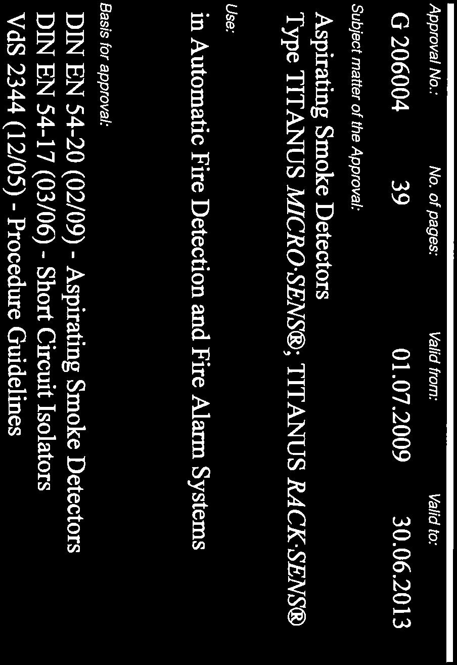


189
190
191


192
FCS-320-TM Aspirating Smoke Detector FCS-320-TM FCS-320-TM-R. Operation Guide
 FCS-320-TM Aspirating Smoke Detector FCS-320-TM FCS-320-TM-R en Operation Guide FCS-320-TM Aspirating Smoke Detector Table of Contents en 3 Table of Contents 1 General 6 1.1 Introduction 6 1.2 Safety
FAS-420-TM Aspirating Smoke Detector FAS-420-TM. Operation Guide
 FAS-420-TM Aspirating Smoke Detector FAS-420-TM en Operation Guide FAS-420-TM Aspirating Smoke Detector Table of Contents en 3 Table of Contents 1 General 6 1.1 Introduction 6 1.2 Safety Instructions
FCS-320-TM Series Conventional Aspirating Smoke Detectors
 Fire Alarm Systems FCS-320-TM Series Conventional Aspirating Smoke Detectors FCS-320-TM Series Conventional Aspirating Smoke Detectors For connecting to conventional fire panels High deceptive alarm immunity
FAS-420 Aspirating Smoke Detector LSN "improved version" FAS-420. Operation Guide
 FAS-40 Aspirating Smoke Detector LSN FAS-40 en Operation Guide FAS-40 Aspirating Smoke Detector LSN Table of Contents en 3 Table of Contents General 6. Introduction 6. Safety Instructions 6.3 Warranty
Siemens aspirating smoke detector (ASD) for the addressed FDnet/C-NET detector line or for standalone operation
 for the addressed FDnet/C-NET detector line or for standalone operation") Sinteso Cerberus PRO FDA241, FDA221 ASD Aspirating smoke detector Siemens aspirating smoke detector (ASD) for the addressed FDnet/C-NET detector line or for standalone operation Patented technology Early
Sinteso Cerberus PRO FDA241, FDA221 ASD Aspirating smoke detector Siemens aspirating smoke detector (ASD) for the addressed FDnet/C-NET detector line or for standalone operation Patented technology Early
Aspirating Smoke Detection (ASD) Systems Fire Detection
 Systems Fire Detection") Aspirating Smoke Detection (ASD) Systems Fire Detection A complete guide for the fire system specifier, designer and installer Aspirating Smoke Detection WAGNER UK Limited Better Solutions in Fire Protection
Aspirating Smoke Detection (ASD) Systems Fire Detection A complete guide for the fire system specifier, designer and installer Aspirating Smoke Detection WAGNER UK Limited Better Solutions in Fire Protection
Honeywell Air Sampling Devices Data Sheet
 Honeywell Air Sampling Devices Data Sheet Smoke detection with high sensitivity and false alarm immunity Product Overview Honeywell Air Sampling Devices (ASDs) are smoke detectors that actively take air
High-precision aspirating smoke detectors for every requirement SecuriRAS ASD 535, ASD 532 and ASD 531 aspirating smoke detectors
 High-precision aspirating smoke detectors for every requirement SecuriRAS ASD 535, ASD 532 and ASD 531 aspirating smoke detectors FIRE DETECTION SOLUTIONS ASD 535-1 One channel ASD 535-2 Two channels ASD
High-precision aspirating smoke detectors for every requirement.
 High-precision aspirating smoke detectors for every requirement. SecuriRAS ASD 535, ASD 532 and ASD 531 aspirating smoke detectors Securiton AG Alarm and Security Systems Alpenstrasse 20, 3052 Zollikofen,
Honeywell Air Sampling Devices Data Sheet
 Honeywell Air Sampling Devices Data Sheet Smoke detection with high sensitivity and false alarm immunity Product Overview Honeywell Air Sampling Devices (ASDs) are smoke detectors that actively take air
TX7130. Conventional Reflective Beam Detector Installation and Operation Manual. TANDA UK Technology Copyright 2015, All right reserved.
 TX7130 Conventional Reflective Beam Detector Installation and Operation Manual Technology Copyright 2015, All right reserved. Product Safety To prevent severe injury and loss of life or property, read
AirUnit. Installation instructions. mfh systems modern floor heating. Decentralised domestic ventilation
 mfh systems modern floor heating AirUnit Decentralised domestic ventilation Installation instructions List of contents, Installation instructions Page 1. General information... 03 2. Function / planning
Installation and Operation Manual
 [Please read this installation & operation manual before install and use this Installation and Operation Manual Address: 8-701,Dongfangming Industry Zone, Dabao Road., Baoan, Shenzhen, China-518101 Page
ASD 535 Aspirating smoke detector
 ASD 535 Aspirating smoke detector From production number 3072 and FW version 0.06.00 The ASD 535 aspirating smoke detector performs the task of taking continuous air samples via one or two sampling pipe
Protecting you and your home
 Gira smoke alarm device Dual Q Dual Q sounds the alarm when dangerous smoke formation is detected and fulfils the increased Q-Label quality requirements. Dual Q is a combined heat and smoke detector, thanks
Consultant Specification AGILE Wireless Fire Detection System
 Contents Scope of Work... 2 The EN54 Part 2 & 4 Fire System... 2 Standards... 2 Wireless Intelligent Photoelectric Smoke Detector Specification... 4 Wireless Intelligent Thermal Heat Detector Specification...
TOOLS 8000 SOFTWARE FOR THE ENTIRE LIFE CYCLE OF YOUR FIRE DETECTION SYSTEMS
 TOOLS 8000 SOFTWARE FOR THE ENTIRE LIFE CYCLE OF YOUR FIRE DETECTION SYSTEMS ONE SOFTWARE FOR ALL TASKS tools 8000 is the complete software tool for your fire detection systems. It accompanies you during
Air Sampling Smoke Detection
 Air Sampling Smoke Detection Notifier by Honeywell: Data Sheet Air Sampling Smoke Detection Data Sheet The Notifier by Honeywell range of air sampling smoke detection systems (ASSD) comprises smoke detectors
Procedure for the Approval of New Fire Detection and Alarm Technologies
 VdS Guidelines for Automatic Fire Detection and Fire Alarm Systems VdS 3469en Procedure for the Approval of New Fire Detection and Alarm Technologies VdS 3469en : 2016-01 (01) Publisher and publishing
Aspirated Smoke Detectors
 Safety Security Certainty LaserSense Aspirated Smoke Detectors We listened to you Aspirated air sampling technology Aspirated smoke detection is a method of smoke detection where the air from the protected
Industrial fire alarm systems
 Industrial fire alarm systems Industrial fire alarm systems redefined. While fire alarm systems for standard applications, e.g. in offices and residential buildings, provide an enormous variety of solutions,
Industrial Fire Detection
 Industrial Fire Detection A new definition of Industrial Fire Detection. While there is a huge variety of solutions available for fire detection technology in standard applications, such as office and
EVC-P CONVENTIONAL PHOTOELECTRIC SMOKE DETECTOR. instruction manual. evolution EVC-P Conventional Photoelectric Smoke Detector
 EVC-P CONVENTIONAL PHOTOELECTRIC SMOKE DETECTOR instruction manual Ref No: NISM/EVC-P/03 Date: Jan 2010 Issue: 3 Quality System Certificate No. 041 Assessed to BS EN ISO 9001:2000 NITTAN (UK) LTD. Hipley
Open-area Smoke Imaging Detection (OSID)
") Open-area Smoke Imaging Detection (OSID) www.xtralis.com/osid Large, open spaces warehouses, airports, train stations, stadiums and shopping malls pose unique challenges to reliable fire detection due
Open-area Smoke Imaging Detection (OSID) www.xtralis.com/osid Large, open spaces warehouses, airports, train stations, stadiums and shopping malls pose unique challenges to reliable fire detection due
designed for rail 5000 Series
 designed for rail 5000 Series 5000 Series The only complete SIL system 20 years of experience in the field. More than 15.000 systems supplied worldwide. A team devoted to rolling stock projects with specialized
Air Comfort. Installation instructions (English) A
 A") Air Comfort Installation instructions (English) WWW.BRINKAIRFORLIFE.NL 614788-A This appliance may be used by children as of 8 years of age, persons of reduced mental or physical capacities and those of
Air Comfort Installation instructions (English) WWW.BRINKAIRFORLIFE.NL 614788-A This appliance may be used by children as of 8 years of age, persons of reduced mental or physical capacities and those of
Technical Description. Laboratory Climate Test Chamber. System Weiss. Mat. No.: Type WKL 34/40
 Technical Description Laboratory Climate Test Chamber System Weiss Mat. No.:67592625 Type WKL 34/40 FACTS The test chambers types WTL/WKL with compact exterior dimensions were especially developed for
IQ8Control C Fire Alarm Panel
 IQ8Control C Fire Alarm Panel State-of-the-art processor technology Maximum cable length for esserbus: 3,500 m Graphics supported, high performance programming tool Innovative alarm signalling by means
Instruction Manual. Alarm Unit For Low Gas Level # Read manual before use! Observe all safety information! Keep manual for future use!
 Mess-, Regel- und Überwachungsgeräte für Haustechnik, Industrie und Umweltschutz Lindenstraße 20 74363 Güglingen Telefon +49 7135-102-0 Service +49 7135-102-211 Telefax +49 7135-102-147 info@afriso.de
Line Smoke Detector LRMX
 Line Smoke Detector LRMX Motorized detector head User-friendly commissioning via automatic selfadjustment Disturbance-protected operation via automatic electromechanical tracking of the detector head during
A T L A S - SolarClimatic Test Cabinet SC 2000 MHG
 A T L A S - SolarClimatic Test Cabinet SC 2000 MHG A T L A S - SolarClimatic Type Test chamber capacity SC 2000 MHG approx. 3400 l Radiation area approx. 1.36 m 2 TECHNICAL DATA Characteristic values for
HART XL High Sensitivity Smoke Detection
 High Sensitivity Smoke Detection Hart XL High Sensitivity Smoke Detection (HSSD) TM is a smoke detection system that is simple to install, commission, service and use yet remains brilliantly capable in
FDCW221 / DOW1171 / SMF121 SMF6120 (repair/replacement) Radio fire detection system
 Radio fire detection system") FDCW221 / DOW1171 / SMF121 SMF6120 (repair/replacement) Radio fire detection system Addressed (FDnet) Sinteso Full integration into FS20, SIGMASYS, and AlgoRex fire detection systems Simultaneous operation
FDCW221 / DOW1171 / SMF121 SMF6120 (repair/replacement) Radio fire detection system Addressed (FDnet) Sinteso Full integration into FS20, SIGMASYS, and AlgoRex fire detection systems Simultaneous operation
Bosch Smart Home. Motion Detector Instruction Manual
 Bosch Smart Home Motion Detector Instruction Manual Start making your home smart! Please be sure to install the Bosch Smart Home Controller first. Ensure that you have a Bosch Smart Home Controller and
Open-area Smoke Imaging Detection (OSID)
") Open-area Smoke Imaging Detection (OSID) OSID Smoke Detection Open-area Smoke Imaging Detection (OSID) by Xtralis is a new innovation in projected beam smoke detection technology. By using advanced dual
Open-area Smoke Imaging Detection (OSID) OSID Smoke Detection Open-area Smoke Imaging Detection (OSID) by Xtralis is a new innovation in projected beam smoke detection technology. By using advanced dual
Original operating instructions Safety switch with guard locking AC901S AC902S
 Original operating instructions Safety switch with guard locking AC901S AC902S 7390914/03 01/2017 Contents 1 Preliminary note...4 1.1 Explanation of symbols...4 2 Safety instructions...4 3 Items supplied...5
TX7100. Intelligent Addressable Optical Smoke Detector Installation and Operation Manual. TANDA UK Technology Copyright 2015, All right reserved.
 TX7100 Intelligent Addressable Optical Smoke Detector Installation and Operation Manual Technology Copyright 2015, All right reserved. Product Safety To prevent severe injury and loss of life or property,
Compressed air preparation Compressed air storage Moisture management. Catalog #1
 Compressed air preparation Compressed air storage Moisture management Catalog #1 This Catalogue is valid from May 2015. All previous catalogues lose their validity with the publication of the new catalogue.
Product data sheet Palas Fidas 200 S
 Product data sheet Palas Fidas 200 S Applications Regulatory environmental monitoring in measuring networks Ambient air measurement campaigns Oriented indicative measurements (spot checks) Long-term studies
Comfort Ceiling Fan Coil System INDULVENT ec. Draught-free ambient air distribution with cooling capacity up to 2600 W
 Comfort Ceiling Fan Coil System INDULVENT ec NEW Draught-free ambient air distribution with cooling capacity up to 2600 W Low sound power levels Only electrical, cooling water and condensate connections
LaserFOCUS VLF-250 Engineering Specification
 Vision Fire & Security LaserFOCUS VLF-250 Engineering Specification May 2004 Part Number 20296 LaserFOCUS VESDA 2 VESDA LaserFOCUS Contents Scope...4 Description...4 General...4 Approvals...4 Codes, Standards
LASER ASPIRATED SMOKE DETECTOR
 LASER ASPIRATED SMOKE DETECTOR LASD1 (Single Channel) INSTALLATION, OPERATION & MAINTENANCE INSTRUCTIONS (CE) 1 INTRODUCTION The LASD1 utilises one or two high-sensitivity laser point detectors in an aspirated
Operating instructions
 MA00929301 09/2015 Operating instructions ED10429002 ESYLUX GmbH An der Strusbek 40 22926 Ahrensburg Germany info@esylux.com www.esylux.com 1 Table of contents 1 Using the manual 8 2 Safety instructions
Flame Monitor for Multiple Burner Furnaces D-LE 603 D-UG 660
 Selectivity Adjustable by Means of - High Pass Frequency Filter - Gain - Threshold Different Adjustments for Different Conditions (e.g. According Fuel or Combustion Technology) Possible, to be Activated
HART XL High Sensitivity Smoke Detection
 High Sensitivity Smoke Detection The Hart XL High Sensitivity Smoke Detection system (HSSD) is an aspirating fire detection system designed to give very early indication of an incipient fire condition.
GMA Panels with double busbar
 L1 L2 L3 GAS-INSULATED SWITCHGEAR >> GMA Panels with double busbar Operating Instructions No. AGS 532 521-01 Edition 09/07 (Supplement to Operating Instructions AGS 531 521-01) Technical Instructions AREVA
AirUnit. Operating manual. mfh systems modern floor heating. Decentralised domestic ventilation
 mfh systems modern floor heating AirUnit Decentralised domestic ventilation Operating manual List of contents, Operating manual Page 1. General information... 02 2. Device description... 03 3. Adjustment
Flexible Air-sampling Smoke Detection
 Flexible Air-sampling Smoke Detection BY Technology Pioneers in Highsensitivity Air-sampling Smoke Detection Systems Providing Solutions Beyond Traditional Smoke and Fire Detection Hochiki, a world-leader
SCHMIDT LED Measured Value Display MD Instructions for Use
 SCHMIDT LED Measured Value Display MD 10.010 Instructions for Use Table of Contents 1 Important Information... 3 2 Application range... 4 3 Mounting instructions... 4 4 Electrical connection... 6 5 Signalizations...
Interface and EOL Modules 8
 Interface and EOL Modules Interface Modules Series 420 25 Interface Modules Series 100 291 EOL Modules 293 254 Interface and EOL Modules Interface Modules Series 420 Interface Modules Serie 420 Interface
Solution F2. Fire Alarm Control Panels one step ahead.
 Solution F2 Fire Alarm Control Panels one step ahead. Sicherheitstechnik Sicherheitstechnik GmbH GmbH The Fire Alarm Control Panel Solution F2 Solution F2 in B2 enclosure (B01090-00) The Concept The Solution
TrueAlarm Analog Sensing
 TrueAlarm Analog Sensing UL, ULC Listed, CSFM Approved* Features Air aspiration duct smoke detection** system provides remote sensor location for ducts with difficult service access: Available as either
DOW1171 / DCW1151 Radio fire detection system
 DOW1171 / DCW1151 Radio fire detection system Interactive AlgoRex Complete integration in the interactive fire detection system CS1140 Simultaneous operation of wired and wireless fire detectors New possibilities
OPERATING MANUAL Enertronic Control System 2
 OPERATING MANUAL Enertronic Control System 2 The integrated control system for Lennox chillers in the Ecologic range Manufacturer: Lennox Benelux B.V. Postbus 1028, 3860 BA NIJKERK Watergoorweg 87, 3861
Control and Indicating Equipment
 VdS Guidelines for Fire Detection and Fire Alarm Systems VdS 2540en Requirements and Test Methods VdS 2450en : 2018-12 (03) Publisher and publishing house: VdS Schadenverhütung GmbH Amsterdamer Str. 172-174
MBZ300. Emergency power control unit. GB Installation instructions MBZ300 MBZ300 MBZ300 MBZ300 MBZ300 MBZ300 MBZ300 PME PME. Reset.
 24V 24V PME PME CM DM SM DM WM Reset Reset Emergency power control unit GB Installation instructions 1 Table of contents 1 Symbols and illustrations...3 2 Product liability...3 3 Safety instructions...3
RS Pro Infrared Temperature Sensor
 Instruction Manual RS Pro Infrared Temperature Sensor Stock Number: 161-8103 Introduction The RS Pro Infrared Temperature Sensor is a device for measuring the temperature of the surface of a solid or liquid
Branching and Connection Box AAB. Operating manual AAB EN11. GTE Industrieelektronik GmbH
 AAB 430-2410-001 EN11 EN Operating manual Branching and Connection Box AAB GTE Industrieelektronik GmbH Helmholtzstr. 21, 38-40 D-41747 Viersen, GERMANY info@gte.de +49(0)2162 / 3703-0 www.gte.de Branching
Performance Specifications LSF LIFT-SMOKE-FREE
 Performance Specifications LSF LIFT-SMOKE-FREE Lift shafts and machinery rooms must be ventilated and equipped with a smoke and heat exhaust ventilation (SHEV) system in accordance with the currently valid
FA compressed air plants (refrigeration/adsorption driers) - granulate driers - medical gases - non-corrosive gases, e. g.
 - granulate driers - medical gases - non-corrosive gases, e. g.") INSTRUCTION MANUAL FA 400 Humidity measuring instruments with display and alarm for measurement of the pressure dew point and the atmospheric dew point in different applications: - compressed air plants
INSTRUCTION MANUAL FA 400 Humidity measuring instruments with display and alarm for measurement of the pressure dew point and the atmospheric dew point in different applications: - compressed air plants
ON-TRACK FOR TAILORED FIRE PROTECTION. Future-proof fire protection solutions for rail vehicles
 ON-TRACK FOR TAILORED FIRE PROTECTION Future-proof fire protection solutions for rail vehicles Fire detection systems Extinguishing systems Water mist systems Challenges FIRE PROTECTION IN RAIL VEHICLES.
Installation Instructions for Honeywell ALL-SPEC Air Sampling Smoke Detection System
 Installation Instructions for Honeywell ALL-SPEC Air Sampling Smoke Detection System Operating indicator light Alarm indicator light for detector module II Alarm indicator light for detector module I Indicator
FC330A-ECO Auto-addressing analogue 1-Loop fire detection panel
 FC330A-ECO Auto-addressing analogue 1-Loop fire detection panel Synova TM Commissioning in no time thanks to automatic address allocation Auto-addressing makes setting dip switches unnecessary Automatic
Quick Selection Guide Fire Systems LSN Periphery
 Local SecurityNetwork Easy wiring Auto configuration capability (self-learning mode) Central programming of all device configurations from the panel Flexible network structure (Loop, stub, T-tap & mixed
FAS 420 Series Aspirating Smoke Detectors LSN improved version
 Fire Alarm Systems FAS 420 Series Aspirating Smoke Detectors LSN improved version FAS 420 Series Aspirating Smoke Detectors LSN improved version www.boschsecrity.com Connectable to the fire panels FPA
Table of Contents. 1. Mounting Tips... 2
 Table of Contents 1. Mounting Tips............................................. 2 1.1. Connections and DIP switch settings................................... 3 1.2. Mounting the Fireray 50/100RV........................................
Centaur TM II Cube Slave Alarm Signalling Equipment INSTALLATION GUIDE
 Centaur TM II Cube Slave Alarm Signalling Equipment INSTALLATION GUIDE General Description This guide provides a summary for installing and configuring the Centaur TM Cube Slave Alarm Signalling Equipment
Panel Mounted Fault Annunciator Series
 Panel Mounted Fault Annunciator Series BSM / USM Panel-mounted fault annunciator Annunciators for panel mounting with 8, 16, 24, 32, 40 and 48 signal inputs Status retention of inputs and sequence in case
FDA241, FDA221 Siemens ASD
 FDA241, FDA221 Siemens ASD Patented Technology Sinteso TM Cerberus PRO Compatible with the Siemens FDnet/C-NET loops (requires FDCC221S option) Advanced dual Wavelength optical detection (Blue & Infra-red)
SecuriFire SecuriLine extended board B5-DXI2
 SecuriFire SecuriLine extended board B5-DXI Technical description Securiton AG Alpenstrasse 0 305 Zollikofen Switzerland T 8 3 en c Imprint Imprint This document, T 8 3, is valid only for the product
Expert Report. Future-proof regulating and control technology boiler systems
 Future-proof regulating and control technology boiler systems 2 Expert Report Dipl.-Wirtschaftsing. (FH), Dipl.-Informationswirt (FH) Markus Tuffner, Bosch Industriekessel GmbH Future-proof regulating
Optical Smoke Detector Heat Detector Manual Call Point Output Unit Isolator
 TECHNICAL GUIDE Optical Smoke Detector Heat Detector Manual Call Point Output Unit Isolator The XPlorer Range XPlorer is a new range of analogue addressable detectors and interfaces developed for all who
Viewguard Motion detctors PIR and DUAL detectors
 Motion detctors and DUAL detectors Passive infrared sensor Passive infrared and microwave sensor AM DUAL AM DUAL Variations detectors: - AM /BUS-1 VdS Class C EN 5131-1 and EN 5131-2-2, grade 3 - /BUS-1
LASER ASPIRATED SMOKE DETECTOR
 LASER ASPIRATED SMOKE DETECTOR LASD2 (Dual Channel) INSTALLATION, OPERATION & MAINTENANCE INSTRUCTIONS (CE) 1 INTRODUCTION The LASD2 utilises two, high-sensitivity laser point detectors in an aspirated
CerberusTM. PRO intelligent protection. A comprehensive fire protection system. Answers for infrastructure.
 CerberusTM PRO intelligent protection A comprehensive fire protection system Answers for infrastructure. Cerberus PRO intelligent protection Fire safety is all about protecting people and assets and securing
Device Technology. Supply Operating voltage Implemented via the bus KNX: V DC XIB: 12 V DC (rated voltage) Voltage range: 10.
 Voltage range: 10.") 2 Device technology XS/S 1.1 2CDC 071 115 F0008 The Interface XS/S 1.1 integrates the Intrusion Alarm Panel L240 into the KNX intelligent installation system. It is connected to the XIB bus of the Intrusion
2 Device technology XS/S 1.1 2CDC 071 115 F0008 The Interface XS/S 1.1 integrates the Intrusion Alarm Panel L240 into the KNX intelligent installation system. It is connected to the XIB bus of the Intrusion
Master devices. Type X-AIR-ZMAS. Zone master module for up to 25 zone modules, with integral webserver and interfaces to higher-level systems
 X X testregistrierung Type Web server, also for mobile devices Zone modules Zone master module for up to 25 zone modules, with integral webserver and interfaces to higher-level systems X-AIRCONTROL zone
C-9105R Conventional Reflective Beam Detector Installation and Operation Manual. (Issue 2.01, February 2006)
") (Issue 2.01, February 2006) CONTENTS I General... 1 II Features... 1 III Technical Specifications... 1 IV Structure and Operation Principle... 2 V Mounting and Wiring... 4 1. Ambient Conditions for Installation...
(Issue 2.01, February 2006) CONTENTS I General... 1 II Features... 1 III Technical Specifications... 1 IV Structure and Operation Principle... 2 V Mounting and Wiring... 4 1. Ambient Conditions for Installation...
SERVICE INSTRUCTIONS FOR. Fire Alarm System MINI-2000
 SERVICE INSTRUCTIONS FOR Fire Alarm System MINI-2000 Version 1.3 02.04.1998 Jari Ollila Tom Brunberg Oy Esmi Ab Copyright Oy ESMI Ab, 1991... 1998 The copyright to the documentation herein is the property
FIRERAY 5000 range USER GUIDE
 FIRERAY 5000 range USER GUIDE 0044-003-04 IMPORTANT PLEASE NOTE: The beam path MUST be kept clear of obstructions at all times! Failure to comply may result in the Detector initiating a Fire or Fault signal.
FDOOT221, FDO221, FDT221
 Sinteso C-LINE FDOOT221, FDO221, FDT221 Automatic fire detectors For the automatically addressed detector bus FDnet The ideal fire detector for every application Signal processing with detection algorithms
Fire detection and alarm
 Fire detection and alarm Aesthetic Install all cabling and cable containment neatly and unobtrusively, meeting the highest electrical industry installation standards. Neatly lay and securely fix cables.
SIMRAD GD10PE IR GAS DETECTOR
 SIMRAD GD10PE IR GAS DETECTOR Operating Manual P3404E 1st edition Jan. 2004 www.simrad-optronics.com CONTENTS 1. PRODUCT DESCRIPTION... 5 1.1 General description... 5 1.2 Construction... 5 1.3 Application
AXIAL FAN User s manual. Quiet-dMEV 100 DC.
 AXIAL FAN User s manual Quiet-dMEV 100 DC www.ventilation-system.com CONTENTS Delivery set... 6 Brief description... 6 Operating guidelines... 6 Designation key... 7 Installation and set-up... 7 Fan options...
Instruction manual. Digital Radar Motion Detector with Infrared Remote Control MWD BF. FEIG ELECTRONIC GmbH Lange Straße Weilburg/Lahn
 Instruction manual Digital Radar Motion Detector with Infrared Remote Control MWD BF FEIG ELECTRIC GmbH Lange Straße 4 35781 Weilburg/Lahn 22.08.02 MWD BF Instruction manual General Copyright 2002 by FEIG
Aspirating Smoke Detection for Duct Monitoring
 Aspirating Smoke Detection for Duct Monitoring Aspirating Smoke Detection for Duct Monitoring Ducts present a challenge for many traditional fire detectors due to environmental factors like high airflow
Installation and operation manual DPC200 - DIFFERENTIAL PRESSURE CONTROLLER. Low pressure with PI-control-mode
 Installation and operation manual DPC200 - DIFFERENTIAL PRESSURE CONTROLLER Low pressure with PI-control-mode Manufacturer: Phone: Fax: E-Mail: Website: Issue: Doc.-no.: Arthur Grillo GmbH Am Sandbach
FDOOT241-A3, FDOOT241-A4, FDOOT241-A5, FDOOT241-A9, FDOOT241-8
 Sinteso S-LINE FDOOT241-A3, FDOOT241-A4, FDOOT241-A5, FDOOT241-A9, FDOOT241-8 Multisensor fire detectors Multi-sensor fire detector for gradual modernization with ASAtechnology For the modernization of
MODEL 5100 VOTING LOGIC MODULE
 DESCRIPTION DESCRIPTION The SST Model 5100 Multi-Input Voting Logic Module is used to monitor the status of up to 14 different points in a hazard zone, and report when a selectable number of these points
SIL2-Interface/ -Signal Conditioners Series DuoTec
 SIL2-Interface/ -Signal Conditioners Series DuoTec Certified according IEC 61508/ 61511 SIL2 DIN-Rail- and 19 -Mounting Since 1970 - Mütec Instruments GmbH Introduction To achieve a maximum safety in production
ASA linear smoke detector
 Sinteso / Cerberus PRO ASA linear smoke detector FDL241-9 Linear smoke detector, used addressed or collectively, ASAtechnology TM Reliable smoke detection in large spaces (indoor application) Detection
PROPOINT PLUS ASPIRATING SMOKE DETECTION SYSTEM
 PROPOINT PLUS ASPIRATING SMOKE DETECTION SYSTEM USER MANUAL Protec Fire Detection plc, Protec House, Churchill Way, Nelson, Lancashire, BB9 6RT, ENGLAND +44 (0) 1282 717171 www.protec.co.uk sales@protec.co.uk
Simplex Panel Interface Guide
 Simplex Panel Interface Guide February 2016 SATEON Software Integrations Simplex Panel Interface Guide Issue 1.0, released February 2016 Disclaimer Copyright 2016, Grosvenor Technology. All rights reserved.
CO2 Gas Warning System Assembly and Operating Instructions
 CO2 Gas Warning System Assembly and Operating Instructions EURO-GAS MANAGEMENT SERVICES LTD CHURSTON HOUSE, BASCOMBE ROAD, CHURSTON FERRERS, DEVON, TQ5 0JJ, UK : +44 (0)1803 844414 Fax: +44 (0)1803 844224
Certificate: / 29 April 2014
 Test report: 936/21217455/A of 10 September 2013 Initial certification: 01 April 2014 Expiry date: 31 March 2019 Publication: BAnz AT 01 April 2014 B12, chapter I, No. 1.1 Approved application The tested
compact office 24V compact office 24V Lux
 Presence detector compact office 24V compact office 24V Lux Art. Nr. 201 4 000 Art. Nr. 201 4 001 D F GB E I NL S N FIN DK Bedienungsanleitung 2 Notice d utilisation 22 Installation manual 42 Manual de
Universal fault annunciator for panel mounting
 Universal fault annunciator for panel mounting Communication over Ethernet USM - Universal-fault annunciator for panel mounting Low depth housing for panel mounting Versions with 8, 16, 32 or 48 inputs
FDF Sinteso Cerberus PRO Cerberus FIT. Flame detector. Flame detector addressed or collective, ASAtechnology TM
 Sinteso Cerberus PRO Cerberus FIT FDF241-9 Flame detector Flame detector addressed or collective, ASAtechnology TM Reliable detection using three infrared sensors and ASAtechnology (indoor and outdoor
Fiber Optic Cable Fence Disturbance Sensor
 Architectural & Engineering Specification for Fiber Optic Cable Fence Disturbance Sensor Purpose of document This document is intended to provide performance specifications and operational requirements
Overview. Wireless Overview QLD NSW VIC Fundamentals. Operation. Features.
 Wireless Overview www.incitefire.com.au Overview Fundamentals FIREwave is a wireless based family of products which is fully integrated into Hochiki s renowned ESP intelligent hardwired system. This seamless