DUAL OPTIC. Installation manual
|
|
|
- Hilary Sutton
- 6 years ago
- Views:
Transcription


1 DUAL OPTIC Installation manual
2 INDEX 1 COMPONENTS Pag. 3 2 MOUNTING EXAMPLES Pag. 4 MOUNTING WITH BRACKETS Pag. 5 3 INSTALLATION EXAMPLES Pag. 6 4 CABLES AND CABLING Pag. 7 CONNECTION AND HEATING SETTING Pag. 8 5 OPTICAL CONFIGURATION Pag. 9 TX OPTICAL Pag. 9 RX OPTICAL Pag RX/TX SETTINGS Pag RX/TX SETTINGS Pag COLUMN ALIGNEMENT Pag CALIBRATION THROUGH SMA SYSTEM Pag CALIBRATION WITH PARALLEL BEAMS Pag CALIBRATION WITH CROSSING BEAMS Pag SETTINGS AND PROGRAMMING SCHEDA QUAD TX Pag. 19 DIP SWITCHES DESCRIPTION Pag. 20 LED DESCRIPTION Pag. 20 CONNECTOR DESCRIPTION & FUNCTIONALITY Pag SETTINGS AND PROGRAMMING QUAD RX Pag. 21 DESCRIPTION DIP SWITCHES Pag. 22 DIP SW 1 Pag. 22 DIP SW 2 Pag. 22 LED DESCRIPTION Pag. 23 CONNECTOR DESCRIPTION & FUNCTIONALITY Pag RESPONSE TIME SETTINGS Pag TECHNICAL CHARATTERISTICS Pag. 24 Installation recommendation Verify that the beam tower is fully watertight once the cover and end caps have been correctly filled at the end of the installation. Use the cable glands supplied on the tower for all cabling must pass through the lower end cap using the cable glands supplied. The missed used of proper accessories decrease the IP grade protection of the tower. Avoid any type of obstruction between the transmitter and receiver. Avoid installing the receivers beams in a position where direct sunlight, at the same angle as the receivers beams, can enter directly into optics especially at sunset and sunrise Do not install multiple beams where the transmitter beam can interfere with other receiver beams. It is always better place either transmitter or receivers back to back. POLITEC s.r.l. Sandor QUAD-ESA SMA Manual Ver


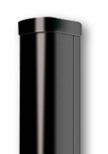
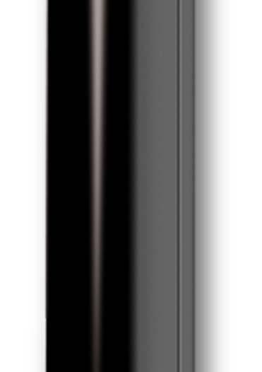
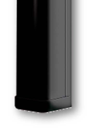
3 1 MAIN COMPONENTS LIST N Descrizione Parte 1 Aluminium profile 2 IR cover 3 Caps 4 Opticals RX/TX 5 Terminals board 6 Mother board POLITEC s.r.l. Sandor QUAD-ESA SMA Manual Ver
4 2 MOUNTING SAMPLES Pole mounting with SAN/PL Wall mounting with SAN/SD Wall mounting with SAN/PL POLITEC s.r.l. Sandor QUAD-ESA SMA Manual Ver
 along the wall to avoid small obstacles (hinges, edges of window sills,...) that could create signal attenuation. POLITEC s.r.l. Sandor QUAD-ESA SMA Manual Ver. 2.5 5")
5 MOUNTING WITH BRACKETS Insert the bracket on the back Pole mounting with SAN/PL Diameter pole max 48 mm Wall mounting with SAN/PL Wall mounting with SAN/SD N.B.: we recommend the use of the brackets SAN / PL on the wall when you place the protection of gates (windows, doors,...) along the wall to avoid small obstacles (hinges, edges of window sills,...) that could create signal attenuation. POLITEC s.r.l. Sandor QUAD-ESA SMA Manual Ver


6 3 INSTALLATION EXAMPLES For an installation to control the perimeter install the barriers as shown: For an installation of barriers overlapped position the barriers as well as in the figure: TX RX RX TX POLITEC s.r.l. Sandor QUAD-ESA SMA Manual Ver
7 4 CABLES AND CABLING The wiring requires to SEPARATE the power cable 12Vdc (ex. 2x0.5 + Nx0.22),to the power cable for heaters 24Vac (ex. 2x0.75) to prevent input of disorders of the AC voltage on the barrier. N.B. is absolutely necessary to shield the cable that provides 12 Vdc power supply and put the metal braid to ground. The cable size depends on the consumption of the columns and the resistance of the cable to the distances involved. The table shows the cable sections and the relative distances to which they provide optimum performance using the supplier LAR22 (12Vdc - 2,5A / 24V AC-300W) and a barrier SANDOR QUAD / ESA SMA. Cable section 12Vdc 24Vac 0,5 mm² 165 m 35 m 0,75 mm² 245 m 50 m 1,5 mm² 490 m 100 m 2,5 mm² 820 m 165 m 4 mm² 1310 m 265 m 6 mm² 1975 m 400 m N.B. THE LAR22 IS NOT WATERPROOF, MUST BE PLACED INSIDE A LOCAL OR PLACED IN A SEALED CONTAINER FOR USE OUTSIDE. Is possible use the power supplier LAR18 (12Vdc 0,9A / 24VAC-60W) to supply a single column. POLITEC s.r.l. Sandor QUAD-ESA SMA Manual Ver


8 CONNECTION AND HEATING SETTING The power of the heaters is by default set to 24 Vac, but you can set it to 12 Vdc repositioning the jumper on both RX and TX mother boards and on each optical as shown. OPTICAL 12Vdc 24Vac MOTHER BOARD 12Vdc 24Vac POLITEC s.r.l. Sandor QUAD-ESA SMA Manual Ver

 or 12V.")

9 5 OPTICAL CONFIGURATION TX OPTICAL TAMPER SUPPLY LED HEATERS SUPPLY 12Vdc 24Va ESA MODEL TX1 TX2 TX3 TX4 TX5 TX To test the functionality of optics TX put ON the DIP 7 and see the activation of the power LED. Set SW4 to supply of the heaters. 24V (standard) or 12V. The voltage can be AC or DC. NB: The settings relating to addresses are already set to Default. POLITEC s.r.l. Sandor QUAD-ESA SMA Manual Ver


10 RX OPTICAL TEST SIGNAL TAMPER LOW SIGNAL LED HEATER SUPPLY 12Vdc 24Vac ESA TX1 TX2 TX3 TX4 TX5 TX To test the functionality of optics TX put ON the DIP 7 and see the activation of the power LED. Set SW4 to supply of the heaters. 24V (standard) or 12V. The voltage can be AC or DC. In the J4 jumper reads the value of the signal in volts. NB: The settings relating to addresses are already set to Default. POLITEC s.r.l. Sandor QUAD-ESA SMA Manual Ver
11 3 RX / TX SETTING The setting of the DIP SWITCH on optical is amended as follows: RX1 TX1 RX2 RX3 TX2 TX3 It should be set to ON the DIP on the motherboard RX exclusion 4 2 RX / TX SETTING The setting of the DIP SWITCH on optical is amended as follows: RX1 RX TX1 TX2 It should be set to ON the DIP on the motherboard RX exclusion POLITEC s.r.l. Sandor QUAD-ESA SMA Manual Ver


12 6 COLUMN ALIGNEMENT For proper alignment, once the barriers are installed, orient the optical of transmitters and receivers in the direction of each other by adjusting the lens holder horizontally through the manual movement after loosening the locking screw on the joint, and vertically through the front screw on the left side of the lens. Vertical adjustment Horizontal adjustment SCREW N.B.: FASTEN THE UNLOCKING SCREW AFTER THE ADJUSTMENT POLITEC s.r.l. Sandor QUAD-ESA SMA Manual Ver
 Fold")


13 7 CALIBRATION THROUGH SMA SYSTEM You can improve the calibration through the use of the supplied filter 1) Fold the device according to the preset creases 2) Place the filter in front of the optics TX placing the two hooks on the pins of the fork optics to refine the search for the signal alignment with critical conditions. You simply apply the filter only on the TX, it is not necessary to repeat the operation on the RX also. 3) Start the alignment of the transmitter is on the barrier by checking the position of the DIP switch 7 to ON and activating the TEST optics TX (1 or 2 or 3 or 4), by pressing the dedicated button for about 3 seconds until the orange LED TEST will lit up. POLITEC s.r.l. Sandor QUAD-ESA SMA Manual Ver
 on coral")


14 DIP 7 ON TO ACTIVATE THE LED DIP 7 ON ORANGE LED TEST BUTTON 4) Place in the corresponding optical TEST (1 or 2 or 3 or 4) on coral receiver, checking the position of the DIP switch 7 to ON and pressing the dedicated button for 3 seconds until the the BUZZER and the LED TEST turns ON, (with high brightness) DIP 7 ON TO ACTIVATE THE LED DIP 7 ON ORANGE LED TEST BUTTON POLITEC s.r.l. Sandor QUAD-ESA SMA Manual Ver
, the")
 indicate a better ALIGNMENT.")

 FIXED and the whistle")
 Exit the function of by repressing the ALIGNMENT TEST button for")

15 5) Through the TRANSMITTER lens shifts, find the maximum optical alignment based on the Buzzer and LEDs (with high brightness), the increase in the frequency of flashing (until the LEDs is fix on and the whistle of the corresponding BUZZER) indicate a better ALIGNMENT. 6) With a FULL rotation on the horizontal RX lens, is carried out the SCANNING of the optical signal. 7) Rotating the lens RX find the maximum value of ALIGNMENT corresponding to the LEDs (with high brightness) FIXED and the whistle of the BUZZER CONTINUOUS. 8) Exit the function of by repressing the ALIGNMENT TEST button for about 3 seconds on both optics (TX-RX) making sure that the orange LED TEST is shown in original condition. 9) When finished, remove the shade that acts as a dampener, having the certainty of having found the optimum value. POLITEC s.r.l. Sandor QUAD-ESA SMA Manual Ver


16 10) Set the DIP switch 7 to OFF to ALL OPTICAL if you want to turn off the LEDs. DIP 7 OFF TO SWITCH OFF THE LED DIP 7 OFF NB: you can SEE the calibration value through the multimeter on each optical receiver. For this procedure, you must have the pair of lenses (TX-RX) in TEST. J4 POLITEC s.r.l. Sandor QUAD-ESA SMA Manual Ver
, and proceed with the calibration as explained above. Put in TEST the optical TX3 and RX3 if present (see p.10-11), and proceed with the calibration as explained above. Put in TEST the optical TX1 and RX1 if present (see p.")
17 8 PARALLEL BEAM CALIBRATION Put in TEST the optical TX1 and RX1 if present (see p.10-11), and proceed with the calibration as explained above. Put in TEST the optical TX2 and RX2 if present (see p.10-11), and proceed with the calibration as explained above. Put in TEST the optical TX3 and RX3 if present (see p.10-11), and proceed with the calibration as explained above. Put in TEST the optical TX1 and RX1 if present (see p.10-11), and proceed with the calibration as explained above. N.B.: during the testing phase of an optical transmitter the other TX not in test are switched off automatically. POLITEC s.r.l. Sandor QUAD-ESA SMA Manual Ver
18 9 CALIBRATION WITH CROSSED BEAMS To activate move the DIP. 4 ON of the board QUAD RX (Chapter 10) Perform the alignement putting on test one optical per time ON Activate the TEST for TX1 and check for proper alignment of optics at a time using the TEST on RX1 and AFTER RX2, RX3, RX4 making sure that TX1 still aligned with RX1. In the same way TEST the TX2, TX3, TX4, NB: It 'requires a minimum distance of at least 8 meters so that the first optical receiver see the last transmitter and vice versa. Especially if you use the ESA configuration with 6 optical receivers, and 6 optical transmitters. POLITEC s.r.l. Sandor QUAD-ESA SMA Manual Ver


19 10 SETTING AND PROGRAMMING QUAD TX TAMPER HEATERS SUPPLY ADJUSTMENT 12 V 12 V 24 V 24 V LED SUPPLY LED HEATERS DIP SWITCHES HEATER SUPPLY Vdc SUPPLY Vdc TAMPER POLITEC s.r.l. Sandor QUAD-ESA SMA Manual Ver
20 DIP SWITCHES DESCRIPTION The board has a single serie of dip switches for the configuration of the transmitter 1 Tx channel 1 2 Tx channel 2 3 Tx channel 3 4 Tx channel 4 5 BEAM 3: 3 TX active 6 BEAM 4: 4 TX active 7 BEAM 5: 5 TX active (ESA) 8 BEAM 6: 6 TX active (ESA) 9 TX OFF: all TX OFF 10 LED: All led active LED DESCRIPTION I led saranno accesi solo se il dip switch 10 è impostato su ON. ON LED POWER LED RISCALDATORI Indicates the mother board ON Indicates the status of heaters. It will be activated if the temperature inside the barrier become below 18 C CONNECTORS DESCRIPTION AND FUNCTIONALITY The connector has: Supply 10-30Vdc Tamper output Supply 12-24Vac-dc for heaters on board QUAD-ESA and on the optical. On the card is provided an input for the tamper. In case of absence of that close the input with a jumper POLITEC s.r.l. Sandor QUAD-ESA SMA Manual Ver


21 11 SETTING AND PROGRAMMING QUAD RX TAMPER HEATERS SUPPLY RESPONSE TIME 12 V 12 V 24 V 24 V SUPPLY LED ALARM LED DISQUALIFICATION LED HEATERS LED DIP SWITCHES 1 DIP SWITCHES 2 AND DISQUALIFICATION HEATERS SUPPLY Vdc ALARM SUPPLY Vdc TAMPER POLITEC s.r.l. Sandor QUAD-ESA SMA Manual Ver
22 DIP SWITCHES DESCRIPTION The card has two series of dip switches where you can set different configurations: DIP SW Tx channel 1 2 Tx channel 2 3 Tx channel 3 4 Tx channel 4 5 BEAM 3: 3 TX active 6 BEAM 4: 4 TX active 7 BEAM 5: 5 TX active (ESA) 8 BEAM 6: 6 TX active (ESA) 9 Relay N.O.: if ON, the alarm relay will be N.O. otherwise it will be N.C 10 All led active DIP SW AND The Barrier goes in alarm only if at least 2 beam are interrupted 2 AND 1-2 The AND condition is only for the beams 1 & 2 3 DISQ Disqualification activated 4 CRO If ON the system will operate with crossed beams ON ON POLITEC s.r.l. Sandor QUAD-ESA SMA Manual Ver


23 The led are active ONLY if the dip 10 is ON LED DESCRIPTION LED POWER LED ALARM LED DISQUALIFICA LED RISCALDATORI Indicates the mother board in ON Goes ON in Alarm Indicates the disqualification active. The alarm relay is inibhited also if the alarm led is ON Indicates the status of heaters. It will be activated if the temperature inside the barrier become below 18 C CONNECTORS DESCRIPTION AND FUNCTIONALITY The connector has: Supply 10-30Vdc Tamper output Supply 12-24Vac-dc for heaters on board QUAD-ESA and on the optical Aarm relay that can be N.O. or N.C. as set before. AND remoted remoto: giving a negative input the system works in AND. DISQUALIFICA: NEGATIVE OPEN COLLECTOR in case of fog On the card is provided an input for the tamper. In case of absence of that close the input with a jumper 12 RESPONSE TIME ADJUSTMENT There is a potentiometer to adjust the TIME OF INTERVENTION. In particular, you can set the barrier for the rapid alert system (cross running) or slow (cross by walk). By adjusting the potentiometer counterclockwise to increase the trip time up to 500ms. In this condition ensures that the alarm of a person walking through the barrier, with the advantage of excluding the possibility of any false alarms (ex. animals). Adjusting the potentiometer clockwise decreases the trip time until 50ms. In this condition ensures the alarm of a person crossing the barrier running at maximum speed. POLITEC s.r.l. Sandor QUAD-ESA SMA Manual Ver
24 13 TECHNICAL CHARACTERISTICS MODELS DUAL SMA QUAD SMA ESA SMA Max range indoor 450 m Max range outdoor 100 m Min distance 4 m 8 m Min Heigh of column 35 cm 1 m 1,5 m 2,0 m Synchronism Optic Beams total 4 (crossed) 16(crossed) 36 (crossed) Alimentazione 12Vdc Power consumption Tx 30 ma+rx 60 ma Tx 30 ma+rx 50 ma Tx 80 ma+rx 80 ma Heaters 10W + 10W 24Vac 20W +20W 24Vca Thermostated 30W+30W 24Vca Thermostated OPERATING TEMPERATURE 25 / +65. Available Kit heaters for temperatures up to -50 C. VERTICAL ADJUSTMENT 20 HORIZONTAL ADJUSTMENT 180 DETECTION FUNCTION AND/OR Tx E Rx ALSO FROM REMOTE ALARM RELAY NC/NO TAMPER NC DISQUALIFICATION OPEN COLLECTOR LED EXCLUDIBLE INFRARED Impulsive double lenses 950 nm PROTECTION DEGREE IP 65 ACCESSORIES FOR WALL MOUNTING ACCESSORIES FOR POLE MOUNTING POLITEC s.r.l. Sandor QUAD-ESA SMA Manual Ver
CONFIGURATION OF THE OPTICALS
 Technical manual INDEX 1 MAIN COMPONENT LIST Pag. 3 2 MOUNTING EXAMPLES Pag. 4 MOUNTING WITH BRACKETS Pag. 5 3 INSTALLATION SAMPLES Pag. 6 4 CONFIGURATION OF THE OPTICALS Pag. 7 OPTICAL TX Pag. 7 OPTICAL
INDEX. Installation recommendation
 Technical manual INDEX 1 MAIN COMPONENTS Pag. 3 2 MOUNTING SAMPLES Pag. 4 MOUNTING WITH BRACKETS Pag. 5 3 INSTALLATION SAMPLES Pag. 6 4 WIRING Pag. 7 5 CONFIGURATION OF THE OPTICALS Pag. 8 OPTICAL TX Pag.
INDICE. Installation recommendation
 Technical manual INDICE 1 MAIN COMPONENT LIST Pag. 3 2 MOUNTING EXAMPLES Pag. 4 MOUNTING WITH BRACKETS Pag. 5 3 INSTALLATION EXAMPLES Pag. 6 4 OPTICS CONFIGURATION Pag. 7 TX Pag. 7 RX Pag. 8 5 SANDOR WS
INDEX. Installation recommendation
 Technical manual INDEX 1 MAIN COMPONENTS Pag. 3 2 ASSEMBLING THE CABLEPIT Pag. 4 CABLE PIT POSITIONING Pag. 6 3 BASE INSTALLATION ON CABLE PIT Pag. 8 4 INSTALLATION EXAMPLES Pag. 9 5 CONFIGURATION OF THE
INDEX. Installation recommendation
 Technical manual INDEX 1 MAIN COMPONENTS Pag. 3 2 ASSEMBLING THE CABLEPIT Pag. 4 CABLE PIT POSITIONING Pag. 6 3 BASE INSTALLATION ON CABLEPIT Pag. 8 4 INSTALLATION EXAMPLES Pag. 9 5 WIRING Pag. 10 6 CONFIGURATION
INFRARED PERIMETRAL BARRIER DOUBLE BEAMS
 INFRARED PERIMETRAL BARRIER DOUBLE BEAMS Index 1 MAIN COMPONENT LIST Pag. 3 2 INSTALLATION TIPS Pag. 5 3 INSTALLATION Pag. 6 WALL MOUNTING Pag. 6 POLE MOUNTING Pag. 6 4 CONNECTIONS AND DESCTIPRIONS Pag.
INFRARED PERIMETRAL BARRIER DOUBLE BEAMS
 INFRARED PERIMETRAL BARRIER DOUBLE BEAMS 1 MAIN COMPONENT LIST Pag. 3 2 SUGGEST FOR INSTALLATION Pag. 5 3 INSTALLATION Pag. 6 WALL MOUNTING Pag. 6 POLE MOUNTING Pag. 6 4 CONNECTIONS AND DESCTIPRIONS Pag.
Installation And commissioning manual. Series S Double Beam 1/16
 Installation And commissioning manual Series S Double Beam 1/16 2/16 Index Main components list Pag. 4 Installation reccomendations Pag. 5 Mounting the bracket Pag. 6 Installation example Pag. 7 Positioning
SANDOR QUAD/ESA. Double beam. POLITEC s.r.l. Installation And commissioning manual
 SANDOR QUAD/ESA Double beam Installation And commissioning manual 1 POLITEC s.r.l. Index Main components list Pag. 3 Installation reccomendations Pag. 4 Mounting the bracket Pag. 5 Installation example
English. Series. Installation and Use Manual
 English Series FOSTER Installation and Use Manual FOSTER Rev.13 03/2015 MITECH srl reserves the right to change the information in this document without warning. Index Anti-intrusion barrier 3 Main components
PARVIS Safe and tranquil thanks to Parvis
 PARVIS Safe and tranquil thanks to Parvis PARVIS MES 9000S PARVIS DUAL PARVIS WS PARVIS SMA A safety system for outdoors, for civil and industrial environments, nts, that integrates e with the garden lighting
Long-Range Barrier Sensors
 Troubleshooting: Receiver LED never turns ON and the buzzer never sounds Buzzer does not sound if the sensor is triggered Receiver LED is ON and the buzzer sounds all the time Test the power and ground
Perimeter protection
 Perimeter protection An invisible sentinel to prevent intrusions Politec Srl has the technology and the expertise to design and manufacture intrusion detection systems, offering the solution for the indoor
DUAL TECHNOLOGY SENSOR (PIR + Microwave) Outdoor use INSTALLATION MANUAL
 Outdoor use INSTALLATION MANUAL") DUAL TECHNOLOGY SENSOR (PIR + Microwave) Outdoor use INSTALLATION MANUAL 1. DESCRIPTION Dual Technology Sensor (PIR + Microwave). AND operation in the prevention of "false alarms". IP65 (indoor and outdoor).
DUAL TECHNOLOGY SENSOR (PIR + Microwave) Outdoor use INSTALLATION MANUAL 1. DESCRIPTION Dual Technology Sensor (PIR + Microwave). AND operation in the prevention of "false alarms". IP65 (indoor and outdoor).
Active Infrared Multi Beam Sensors
 Active Infrared Multi Beam Sensors D Series TECHNICAL MANUAL INDEX GENERAL SAFETY RECOMMENDATIONS 3 CONFORMITY 4 WARRANTY 4 INTRODUCTION 5 FEATURES 5 OPERATIONAL RANGE 6 SETUP TRANSMITTER (TX) 6 SETUP
Active Infrared Multi Beam Sensors. R Series
 Active Infrared Multi Beam Sensors R Series TECHNICAL MANUAL INDEX GENERAL SAFETY RECOMMENDATIONS 3 CONFORMITY 4 WARRANTY 4 INTRODUCTION 5 FEATURES 5 OPERATIONAL RANGE 6 SETUP TRANSMITTER (TX) 6 SETUP
D-Tect 2 GJD300 Quad PIR Movement Detector
 D-Tect GJD0 Quad PIR Movement Detector Package Contents 3. Package Contains: x D-Tect x Drilling template for fixing holes x Allen Key 3 x 3.75mm wall plugs 3 x 3.75mm screws x Spare Sliding Curtains x
D-TECT Introduction. Connecting the Unit. Quick Installation. Multi Beam Alignment & Masking. Mounting the Unit
 D-TECT 2 GJD300 Quad PIR Movement Detector Package Contents Package Contains: 1 x D-Tect 2 1 x Drilling template for fixing holes 3 x 31.75mm wall plugs 3 x 31.75mm screws 2 x Spare Sliding Curtains 2
INFRARED MODULATED BARRIERS
 INFRARED MODULATED BARRIERS riello elettronica group INFRARED BARRIERS WITH ADJUSTABLE LENSES FULL FULL SYNCRO POWER SUPPLY 12/24 Vac-dc MAXIMUM RANGE UNDER IN CONDITIONS 15 METRES CONFORMS TO THE SAFETY
BARRIERE & SENSORI BARRIERS & SENSORS
 BARRIERE & SENSORI BARRIERS & SENSORS Italian Engineering Catalogue 2016 Secured by Innovation Mitech manufactures a complete range of intrusion perimeter barriers of utmost reliability and high quality,
FSLIMPRO
 1. INTRODUCTI FSLIMPRO is especially designed and built for quick and easy installation. Installation is truly made easy and wiring up is minimised (only the power supply cable and alarm contacts require
This symbol indicates prohibition. The specific prohibited action is provided in and/or around the figure.
 No. 59-88-0 INSTALLATION INSTRUCTIONS PHOTOELECTRIC DETECTOR Smart Line series Model SL-00QN SL-50QN SL-650QN Detection range 60m/00ft. 00m/50ft. 00m/650ft. FEATURES Quad high power beams Smart design
ENFORCER SENSOR MANUAL. Multi-Frequency Quad Photobeam Detectors
 Also available from SECO-LARM: E-960-D290Q E-932-D33TBQ E-9622-4B25 Twin Photobeam Detectors Range: up to 290' outdoors. Lensed optics reinforce beam strength and provide excellent immunity to false alarms
perimeter barriers Active infrared SAFET Y INSIDE AND OUTSIDE THE HOME WALL-FLUSH INTERNAL OR EXTERNAL PROTECTION EXTERNAL PROTECTION
 Active infrared The recently updated range of Prastel active infra-red offers many solutions: WALL-FLUSH INTERNAL OR EXTERNAL PROTETION For short range perimeter protection (doors, windows, balconies)
Photobeam 5000 ISC-FPB1-W60QF, ISC-FPB1-W120QF, ISC-FPB1-W200QF. en Installation and Operation Guide
 Photobeam 5000 ISC-FPB-W60QF, ISC-FPB-W0QF, ISC-FPB-W00QF en Installation and Operation Guide Photobeam 5000 Table of Contents en 3 Table of contents Introduction 4. About documentation 4. Bosch Security
Twin Photobeam Detectors Manual
 Also available from SECO-LARM: Twin Photobeam Sensors Quad Photobeam Detectors Curtain / Barrier Sensors Twin Photobeam Detectors Manual Up to 390ft (0m) range Laser-beam alignment Anti-frost system Adjustable
ITALIANO BST-100 ACTIVE INDOOR AND OUTDOOR INFRARED BARRIER WITH 2 BEAMS OF PROTECTION INSTALLATION MANUAL. Manuale istruzioni BST-100. Pag.
 BST-100 ACTIVE INDOOR AND OUTDOOR INFRARED BARRIER WITH 2 BEAMS OF PROTECTION INSTALLATION MANUAL Manuale istruzioni BST-100 Pag. 1 1 - Product Discription The BST-100 is an active indoor & outdoor infrared
GS100-ATEX. Hazardous Areas Infra-Red Beam PULSE MODULATED ACTIVE INFRA-RED BEAM FOR HAZARDOUS AREAS ZONE 1 OR ZONE 2 GENERAL
 GS100-ATEX Hazardous Areas Infra-Red Beam PULSE MODULATED ACTIVE INFRA-RED BEAM FOR HAZARDOUS AREAS ZONE 1 OR ZONE 2 GENERAL The GS100 beam set is a detection device only, and is designed to be used in
Movement Detector GJD 300
 Movement Detector GJD 300 Installation & Set Up Guide Introduction A CCTV event trigger utilising two independent passive infrared detectors combined in a T05 package. Both sensors have to trigger before
AX-100TFR/AX-200 TFR INTRODUCTION 1-1 BEFORE YOUR OPERATION BATTERY OPERATED PHOTOELECTRIC DETECTOR. Warning FEATURES. Caution. Warning.
 FEATURES 4 5 6 No.59-55- 09040 INSTALLATION INSTRUCTIONS N9 BATTERY OPERATED PHOTOELECTRIC DETECTOR AX-00TFR/AX-00 TFR AX-00TFR : Detection range: 0 m (00 ft.) AX-00TFR : Detection range: 60 m (00 ft.)
DHR3. Accessories. NOTE: Set up for this sensor should be performed by an AAADM-certified installer. INSTALLATION INSTRUCTIONS
 NOTE: Set up for this sensor should be performed by an AAADM-certified installer. Section 1 General Description The DHR3 is a combination microwave/infrared sensor providing both motion detection and presence
"Pegaso" wireless alarm system
 "Pegaso" wireless alarm system Summary Page 1.0. Description... 2 2.0. Installation... 3 3.0. Connections to mains power... 4 4.0. Low battery signalling... 4 5.0. Service key... 5 6.0. Selection of functions...
BARRIERS & SENSORS Catalogue 2017
 BARRIERS & SENSORS Catalogue 2017 MADE IN ITALY MITECH Secured by Innovation Mitech manufactures a complete range of intrusion perimeter barriers of utmost reliability and high quality, Made in Italy,
Safety Photo Beam UL MONITORED DEVICE
 IRB-HB Safety Photo Beam UL325-2010 MONITORED DEVICE Operating Instructions CAUTIONS AND WARNINGS This product is an accessory or part of a system. Always read and follow the manufacturer s instructions
Occupancy Sensor LS Descriptions. Product Profile. Technical Specifications
 LS-818-3 Descriptions Temco s Passive Infrared Occupancy Sensor is a low cost comercial and residential surface mount occupancy sensor. Advanced filtering reduces false triggering due to air movement and
ACTIVE INFRARED BARRIER
 Although PROTECH provides high security indoor intrusion sensors for the military and government markets, our specialty is outdoor protection. Since we first introduced our PIRAMID outdoor dual technology
D-TECT Dual Tech. GJD360 Triple Technology External Detector
 D-TECT Dual Tech GJD360 Triple Technology External Detector PACKAGE CONTENTS 1 x Dual Tech 1 x Drilling template for fixing holes 3 x 31.75mm wall plugs 3 x 31.75mm screws 2 x Spare Sliding Curtains 2
UNICA - ALARM SYSTEM WITH VISUAL VERIFICATION. All in One - All in Touch Video - Alarm System
 UNICA - ALARM SYSTEM WITH VISUAL VERIFICATION All in One - All in Touch Video - Alarm System UNICA is a revolutionary alarm system based on architecture all-in-one composed by a burglar alarm (wired and
Elite. GJD022 /GJD023 35m External PIR. Multi Beam Lens Data
 Elite GJD022 /GJD023 35m External PIR Multi Beam Lens Data The GJD multifunction lens fitted to the GJD Elite detector produces 9 long range beams and 9 medium to short range curtain beams. Movement across
Photobeam 5000 ISC-FPB1-W60QS, ISC-FPB1-W120QS, ISC-FPB1-W200QS. en Installation and Operation Guide
 Photobeam 5000 ISC-FPB-W60QS, ISC-FPB-W20QS, ISC-FPB-W200QS en Installation and Operation Guide Photobeam 5000 Table of Contents en 3 Table of contents Introduction 4. About documentation 4.2 Bosch Security
5800-OD Wireless Outdoor Motion Sensor Installation Instructions
 GENERAL INFORMATION The Honeywell 5800-OD Wireless Outdoor Motion Sensor (referred to as the 5800-OD) combines the convenience of wireless technology with a full featured outdoor PIR motion sensor. The
HANDBUCH / MANUAL / MANUEL / MANUALE TopScan-S
 FACTORY AUTOMATION HANDBUCH / MANUAL / MANUEL / MANUALE TopScan-S Certification Type Tested Inhalt / Content / Sommaire / Indice Deutsch......................................................... 3 English.........................................................
l High precision, computer-designed parabolic optical system,. Dual element pyro-electric sensor.
 GENERAL INFORMATION: The No. 1852 provides 12 zones of coverage with a range of up to 25 feet (at a typical mounting height of 7-0 ). This model has the following important features: l High precision,
LZR -FLATSCAN SW SAFETY SENSOR FOR FULL- AND LOW-ENERGY AUTOMATIC SWING DOORS. Visit website for available languages of this document.
 EN LZR -FLATSCAN SW SAFETY SENSOR FOR FULL- AND LOW-ENERGY AUTOMATIC SWING DOORS Visit website for available languages of this document. 75.5947.03 LZR-FLATSCAN SW 20190206 Page 1 of 16 DESCRIPTION 1 2
DH400. Accessories. NOTE: Set up for this sensor should be performed by an AAADM-certified installer.
 NOTE: Set up for this sensor should be performed by an AAADM-certified installer. Section 1 General Description The is a high mount microprocessor controlled active infrared presence detector for all types
ACTIV8 ONE OFF. 1 Tips USER S GUIDE COMBINED RADAR OPENING AND ACTIVE INFRARED SAFETY SENSOR. 1 Description. 2 Symbols.
 ACTIV8 ONE OFF USER S GUIDE COMBINED RADAR OPENING AND ACTIVE INFRARED SAFETY SENSOR 1 Description Cover 2 nd Radar Antenna Radar motion sensor Push-Buttons IR-Presence sensor Radar Antenna clip IR-Prism
PHOTOELECTRIC BEAM SENSOR PR-11BE : OUTDOOR 3.3 to 36ft. (1 to 11m) : INDOOR 3.3 to 49ft. (1 to 15m)
 : INDOOR 3.3 to 49ft. (1 to 15m)") PHOTOELECTRIC BEAM SENSOR PR-11BE : OUTDOOR 3.3 to 36ft. (1 to 11m) : INDOOR 3.3 to 49ft. (1 to 15m) Thank you for purchasing our photoelectric beam sensor. This sensor will provide long and dependable
PHOTOELECTRIC BEAM SENSOR PR-11BE : OUTDOOR 3.3 to 36ft. (1 to 11m) : INDOOR 3.3 to 49ft. (1 to 15m) Thank you for purchasing our photoelectric beam sensor. This sensor will provide long and dependable
Table of Contents. 1. Mounting Tips... 2
 Table of Contents 1. Mounting Tips............................................. 2 1.1. Connections and DIP switch settings................................... 3 1.2. Mounting the Fireray 50/100RV........................................
Description. Optex Incorporated
 Optex Incorporated Description 1845 W. 205 th St. Torrance, CA 90501-1510 USA TEL (310) 533-1500 and (800) 966-7839 FAX (310) 533-5910 Doc: Model: Desc: Architect/ Engineer Specifications CX-502 PIR Intrusion
LZR -FLATSCAN SW SAFETY SENSOR FOR FULL- AND LOW-ENERGY AUTOMATIC SWING DOORS
 EN LZR -FLATSCAN SW SAFETY SENSOR FOR FULL- AND LOW-ENERGY AUTOMATIC SWING DOORS 75.5947.01 LZR-FLATSCAN SW 20180627 Page 1 of 16 DESCRIPTION 1 2 3 4 5 6 7 8 11 12 13 14 15 16 9 10 17 18 1. cover 2. push
Installation Instructions
 Request-to-Exit Dual Technology Motion Sensor 1048889B November 2005 Copyright 2005, GE Security Inc. Introduction This is the GE Request-to-Exit Dual Technology Motion Sensor for models -W, -B, and -G.
WM3000 WIRELESS MODULES
 WM3000 WIRELESS MODULES $$:05 $$:07 INSTALLATION INSTRUCTIONS Table of Contents Installation... 3 Mounting Instructions & Connections... 3 Setting the Dip Switches... 4 Setting the Recognition Time...
FIRE STROBE 2000 INSTALLATION INSTRUCTIONS
 FIRE STROBE 2000 INSTALLATION INSTRUCTIONS I. SITE INSPECTION FOR INSTALLATION A.P.I voice: (858) 292-1561 web: http:// www.firestrobe.com 1. Carefully inspect the area where the Fire Strobe 2000 will
Table of Contents. Page Quick Set-up Instructions 1. Theory of Operation 2. Specifications 3. TM 1003W Controls and Connections 4
 Table of Contents Page Quick Set-up Instructions 1 Theory of Operation 2 Specifications 3 TM 1003W Controls and Connections 4 1. Power Source Connector 5 2. Alarm Output Connector 5 3. Variation Detection
Solar Powered Wireless Photobeam Sensors
 Installation & Operating Manual Solar Powered Wireless Photobeam Sensors SWPB-50 SWPB-100 SWPB-250 SWPB-400 50ft 100ft 250ft 400ft Create a Virtual Wall with the photobeam sensors! FEATURES Detection Range:
Intrusion Outdoor Protection Perimeter
 Intrusion Outdoor Protection Perimeter Borders Commercial industrial Military base Correctional institution VIP Estates/Residences Communication Airports Warehouses Perimeter Sensors: the ideal solution
Reflective Optical Beam Smoke Detector User Guide
 Reflective Optical Beam Smoke Detector User Guide 1. Installation IMPORTANT NOTE: The infrared beam path MUST be kept clear of obstructions at all times! Failure to comply may result in the system initiating
OPTICAL TURNSTILE SYSTEM
 OPTICAL TURNSTILE SYSTEM Installation Instructions OTS-WNG UNPACK TURNSTILES. Remove the bolts at the ends of the turnstiles to separate from the skids and place turnstiles on the floor. With a box knife
Occupancy Sensor LS Descriptions. Product Profile. Technical Specifications
 LS-818-3 Descriptions Temco s Passive Infrared Occupancy Sensor is a low cost comercial and residential surface mount occupancy sensor. Advanced filtering reduces false triggering due to air movement and
PHOTOELECTRIC DUAL BEAM DETECTOR R4222 RECEIVER INDICATORS 1
 PHOTOELECTRIC DUAL BEAM DETECTOR Manual R4222 RECEIVER INDICATORS 1 PARTS GOOD LEVEL ALARM COVER Connection s Indicators Wiring Knockout Response Time Adjustment (only for receiver) Signal Level Test Points
Instruction Manual Model A
 706 Bostwick Avenue, Bridgeport, CT 06605 TEL: 203-368-6751 FAX: 203-368-3747 1-800-566-6822 www.devarinc.com Instruction Manual Model 18-232A LOOP POWERED ALARM MANUAL NO. 990029 MODEL 18-232A LOOP POWERED
INSTALLATION INSTRUCTIONS. This model is UL Listed product. The comment with *UL-Number are UL s requirements and information for using this product.
 (UL) 9176-13-1 (No. 9176-) INSTALLATION INSTRUCTIONS INSTALLATION AND MAINTENANCE NOTES Warning REDWALL-V series This model is UL Listed product. The comment with *UL-Number are UL s requirements and information
English. Italiano. Português. Françias. Español
 DT AM Grade 3 Español Françias Português Italiano English High Ceiling Mount Detector Installation Guide English DT AM Grade 3 High Ceiling Mount Detector Installation Guide General Description The Industrial
D296/D297. Installation Instructions Long-Range Beam Smoke Detectors
 D96/D97 EN Installation Instructions Long-Range Beam Smoke Detectors D96/D97 Installation Instructions.0 Description FCC Compliance Notice This equipment was tested and complies with the limits for a Class
COMPANY PROFILE. a A SOLID REPUTATION. a DETAIL IN MANUFACTURING PROCESS. a SICURIT A TRUSTED SUPPLIER
 COMPANY PROFILE a A SOLID REPUTATION With a solid reputation based on more than 30 year s experience in the field, SICURIT is one of the most reliable and technologically advanced companies in the security
DOLKPL1KB DOLKPS1KB DOLKSF1KB
 DOLKPL1KB DOLKPS1KB DOLKSF1KB USER MANUAL INSTRUCTIONAL VIDEO 1] Connection Terminals 2] Basic Wiring Example 3] Quick Start Guide 4] Programming Guide 5] Specifications 1 Connection Terminals The DOLKPS1KB/DOLKPS1KB/DOLKSF1KB
"Pegaso" wireless alarm system D.I.Y. wireless kit
 "Pegaso" wireless alarm system D.I.Y. wireless kit Summary Page 1.0. Description... 2 2.0. Installation... 3 3.0. Connections to mains power... 3 4.0. Low battery signalling... 4 5.0. Service key... 4
Intrusion. Outdoor protection perimeter
 Intrusion Outdoor protection perimeter Airports Warehouses Military bases Commercial industrial VIP estates/residences Communications Quicker and earlier responses to intrusion events help avoid damages
Fireray Application and. Installation Guide FEATURES. Range metres. 12V to 24V dc operation. Selectable alarm thresholds
 Fireray 2000 pplication and FETURES Installation Guide Range 10-100 metres 12V to 24V dc operation Selectable alarm thresholds Low current consumption Ground level electronics Manual or automatic reset
RCR-REX Request-to-Exit Dual Technology Motion Sensor Installation Guide
 RCR-REX Request-to-Exit Dual Technology Motion Sensor Installation Guide Introduction This is the Interlogix RCR-REX Request-to-Exit Dual Technology Motion Sensor Installation Instructions for models RCR-REX-W,
INSTRUCTION MANUAL & 8200 Monitor. Manual Issue 06
 INSTRUCTION MANUAL 8100 & 8200 Monitor Manual Issue 06 ** This page is intentionally left blank ** Table of Contents 1 Introduction... 4 1.1 Manual Conventions... 4 1.2 Version 4 PCBA's... 4 1.3 Product
Safety Light Curtains Area Access Control
 Presence Sensing Safety Devices Description The AAC photoelectric safety switch is a single-beam, noncontact presence sensing safety device consisting of separate transmitter and receiver units. The light
LUX Hardwired - Installation Notes
 Ness LUX wired PIR with Nightlight Quad element pyro sensor 15m x 15m wide angle coverage Look down Creep Zone Selectable Standard and Pet Aware modes Adjustable sensor mask for No Creep and Pet modes
Commercial Series TriTech Motion Detector. Reference Guide
 Commercial Series riech Motion Detector en Reference Guide Commercial Series riech Motion Detector able of contents en 3 able of contents 1 Safety 4 Introduction 5.1 About documentation 5. Bosch Security
CM-RQE70 PIR REQUEST TO EXIT DETECTOR
 Door Activation Devices CM-RQE70 PIR REQUEST TO EXIT DETECTOR THIS PACKAGE INCLUDES (1) Wiring Harness (2) #6 x 3/4" Screws (2) 3/16" Wall Plugs (6) Wire Nuts (2) 's BP7175 1. GENERAL DESCRIPTION Camden
FIRERAY 2000 EExd Hazardous Area Smoke Detector Installation Guide
 FIRERAY 2000 EExd Hazardous Area Smoke Detector Installation Guide KEY FEATURES Flameproof Receiver and Transmitter Standard Fireray Controller Unit High Coverage - up to 1500 2 m per system Low Cost Beam
Pioneer-R16 Gas Monitor Operator s Manual
 Pioneer-R16 Gas Monitor Operator s Manual Edition 7/2/97 RKI INSTRUMENTS, INC RKI Instruments, Inc. 33248 Central Ave, Union City, CA 94587 (510) 441-5656 Chapter 1: Description About the Pioneer-R16 Gas
SIRA srl. Installation and user manual. Consolle/Digit Remote LCD Annunciator. Remote LCD Annunciator INSTALLATION & USERS MANUAL.
 Page 1 / 15 Installation and user manual Page 2 / 15 Sira s.r.l. reserves the right to make modifications to this manual and the product described herein without prior notice. Sira s.r.l. shall not be
DUAL ZONE OUTDOOR PIR MS-12TE & MS-12FE
 DUAL ZE OUTDOOR PIR MS-12TE & MS-12FE INSTRUCTI MANUAL We appreciate your purchase of a TAKEX passive infrared sensor. This sensor will provide long and dependable service when properly installed. Please
705 Emmett Street Bristol, CT DynaLock MODEL 3101C-TJ101 DELAY EGRESS SYSTEM WIRING INSTRUCTIONS
 BASIC SET-UP 1. Remove the Electronics Cover to expose the circuit board assembly. C L C 2. - System Selector Switches The selector switches (S3) which control major system functions are factory set to
4-Row Active Infrared Presence Detector for Automatic Door Control. Cover
 Section 1 General Description The is a -row microprocessor controlled active infrared presence detector for all types of automatic doors. Wide and narrow pattern width of the sensor is adjustable by twin
HX-80NRAM. High Mount Outdoor Detector
 Battery operated with 2 PIRs and HX-80NRAM anti-masking Battery operated Battery saving logic Compatible with most wireless transmitter Long distance detection area (24.0 m) Flexible detection area setting
Leuze electronic. Dimensioned drawing. Electrical connection. Accessories: 150m ISO 9001
 Throughbeam photoelectric sensors Dimensioned drawing 15m 1-3 V DC A 2 LS Throughbeam photoelectric sensors with high performance reserve in infrared light Robust metal housing with glass cover, protection
1 Safety instructions. 2 Device components. Presence detector. Operating instructions
 Presence detector Standard Art. No. 3361 WW Presence detector Standard Art. No. 3361 AL Presende detector Universal Art. No. 3361-1 WW Presende detector Universal Art. No. 3361-1 AL Operating instructions
DOLKPS1KB Programming & Installation Manual
 VANDAL RESISTANT BACK-LIT WEATHERPROOF ACCESS CONTROL KEYPAD WITH WIEGAND OUTPUT & DATA I/O DOLKPS1KB Programming & Installation Manual FOR ELECTRIC LOCK, INTER-LOCK AND SECURITY SYSTEM INSTALLATIONS DOLKPS1KB
TITLE SLIDE. FIRERAY2000 EExd OPTICAL BEAM SMOKE DETECTOR. Doc. No: Copyright Fire Fighting Enterprises Ltd.
 TITLE SLIDE FIRERAY2000 EExd OPTICAL BEAM SMOKE DETECTOR Doc. No: 32-0009-01 OPTICAL BEAM SMOKE DETECTORS This training material provides information to assist the Fire System Designer and Installer in
RED1. Technical Support And Installation Manual. Models ST, E1, E2, E3, E4, and 420. Approved
 RED1 Models ST, E1, E2, E3, E4, and 420 Technical Support And Installation Manual 210111 FM Approved 1. OVERVIEW 1 2. BASIC OPERATION 3 2.1 General 3 2.2 Field-of-View 4 2.3 Range 4 2.4 Environment 4 2.5
LZR -WIDESCAN. Motion, Presence, and Safety Sensor for Industrial Doors (US version) DESCRIPTION ENGLISH
 DESCRIPTION ENGLISH") LZR -WIDESCAN Motion, Presence, and Safety Sensor for Industrial Doors (US version) ENGLISH DESCRIPTION 6 7 8 9 0 2 3 2 3 4 5 4. main connector 2. protection film 3. laser window 4. USB cap 5. LED display
LZR -WIDESCAN Motion, Presence, and Safety Sensor for Industrial Doors (US version) ENGLISH DESCRIPTION 6 7 8 9 0 2 3 2 3 4 5 4. main connector 2. protection film 3. laser window 4. USB cap 5. LED display
Beacon 410A Gas Monitor Operator s Manual
 Beacon 410A Gas Monitor Operator s Manual Part Number: 71-0397 Revision: F Released: 12/5/17 www.rkiinstruments.com Product Warranty RKI Instruments, Inc., warrants gas alarm equipment sold by us to be
GJD OPAL RFX WIRELESS 35 METRE EXTERNAL PIR INSTALLATION MANUAL
 GJD OPAL RFX WIRELESS 35 METRE EXTERNAL PIR INSTALLATION MANUAL A WIRELESS PASSIVE INFRARED DETECTOR AND THREE CHANNEL RECEIVER THAT SIMULTANEOUSLY OR INDIVIDUALLY CONTROLS CCTV SWITCHERS, VIDEO RECORDERS
PSC-ID-x-CM Series Ceiling Mount Occupancy Sensor
 TECHNICAL SPECIFICATIONS PSC-ID-x-CM Series Ceiling Mount Occupancy Sensor Basic Features Line voltage version: 120-277VAC, 60Hz Low voltage version: 24VDC, requires separate class 2 power supply PIR sensor
Topscan G3 Presence detector for automatic doors
 Topscan G3 Presence detector for automatic doors Your added value! Smallest presence detector of its class User-friendly, solid and simple operation Easy and significantly faster installation Mechanically
RMS/RPX Reader. User Manual
 RMS/RPX Reader User Manual Copyright Disclaimer Trademarks and patents Intended use FCC compliance Copyright 2005, GE Security Inc. All rights reserved. This document may not be copied or otherwise reproduced,
Installing the Cisco ONS FAP-4 Fuse Alarm Panel
 Installing the Cisco ONS 15454-FAP-4 Fuse Alarm Panel Product Number: 15454-FAP-4= This document explains how to install, test, operate, and maintain the Cisco ONS 15454-FAP-4 fuse alarm panel. This document
THE BEST SOLUTIONS FOR OUTDOOR PERIMETER PROTECTIONS
 More than 30 Years of experience in the field, this is the strength that allows SICURIT to be known as one of the most reliable and technologically advanced companies in the security market, providing
Beacon 200 Gas Monitor Operator s Manual. Part Number: RK Released: 6/6/08
 Beacon 200 Gas Monitor Operator s Manual Part Number: 71-2102RK Released: 6/6/08 Table of Contents Chapter 1: Introduction.................................................3 Overview.............................................................3
INSTRUCTION MANUAL T119 1MN0110 REV. 0. operates with ISO9001 certified quality system
 INSTRUCTION MANUAL 1MN0110 REV. 0 operates with ISO9001 certified quality system TECSYSTEM S.r.l. 20094 Corsico (MI) Tel.: +39-024581861 Fax: +39-0248600783 http://www.tecsystem.it R. 1.1 25/08/16 ENGLISH
Infrared Single Light Barrier. Mounting Instructions DO560
 Infrared Single Light Barrier VdS-Approval No. G197078 Mounting Instructions DO560 WANING-Opto-Elektronik GmbH & Co Produktions KG Daimlerstraße 13 63303 Dreieich Planning able of Contents DECLAAION OF
Rota-Sonde DC4000-L. Laser pointer for easy alignment. Remote control of the sensitivity
 Scanning HOT METAL DETECTOR Rota-Sonde DC4000-L Two sensitivity ranges : 400 C and 230 C Laser pointer for easy alignment Remote control of the sensitivity Self-monitoring ISO 9001 Applications Benefits