SONAR PROCESS MONITORING SYSTEM SUPPLEMENT FOR ATEX CLASS I, ZONE 2 SAFETY
|
|
|
- Oscar Phelps
- 6 years ago
- Views:
Transcription
1 SONAR PROCESS MONITORING SYSTEM SUPPLEMENT FOR ATEX CLASS I, ZONE 2 SAFETY
2
3 Table of Contents 1 SCOPE MARKINGS Transmitter [TB8-xx-xx-xx-03] for use with Sensor Head [SH-xxx-xx-xA-xxx-03]: Sensor Head [SH-xxx-xx-xA-xxx-03]: Transmitter [TB8-xx-xx-xx-04]: ATEX ZONE 2 SPECIAL CONDITIONS OF USE RELATED TO THE SYMBOL X Transient Protection Electrostatic Charging Cable Glands Control Drawings Environment STANDARDS CONTROL DRAWINGS SPECIFICATIONS Electrical Parameters Maximum Surface Temperatures OPERATING CONDITIONS UNDER WHICH THIS PRODUCT MAY BE SAFELY USED Scope Hazardous Rating Location of Facility Where It Is To Be Installed System including TB8-xx-xx-xx-03 Transmitter System including TB8-xx-xx-xx-04 Transmitter Installation Site Ambient Temperature, Pressure, Humidity Temperature Barometric Pressure Humidity Water Spray and Dust Explosive Gasses Condition of piping Chemical Environment Mains Power SUPPLEMENTARY INSTRUCTIONS FOR SAFE ASSEMBLY AND INSTALLATION Use Control Drawing, Install Per Code Make Correct Terminal Block Connections Use Cable Glands and/or Conduit Entries Selection of Cable Glands Selection of Conduit Fittings Wire With Power OFF Wire Securely to Terminals and Route Neatly No Foreign Objects Avoid Leaky Pipes Seal Sensor Head Cover Secure The Access Panel SUPPLEMENTARY INSTRUCTIONS FOR SAFELY PUTTING INTO SERVICE Prior to Applying Power Apply Power Perform Setup Verify Proper Operation SUPPLEMENTARY INSTRUCTIONS FOR SAFE USE (NORMAL OPERATION WITH NO OPERATOR INTERVENTION) C Rev 04 Page i
4 10.1 Keep Enclosures Closed During Use Transmitter Sensor Head Periodic Inspections Transmitter Inspections Sensor Head Inspections Cables Inspections Problems Found During Inspection SUPPLEMENTARY INSTRUCTIONS FOR SAFE ADJUSTMENT General Transmitter Adjustments Use of Keypad and RESET Switch Use of USB Memory Stick Interface Use of RJ45 Ethernet Connector Interface Use of DB9 RS232 Connector Interface Sensor Head Adjustments SUPPLEMENTARY INSTRUCTIONS FOR SAFE MAINTENANCE, SERVICING AND EMERGENCY REPAIR General UOS, OFF And No Explosive Gasses Present Notify Control Room Transmitter General Mains Power OFF Fuse Replacement Sensor Terminal Blocks Customer Input / Output and Fieldbus Terminal Blocks Electrical Circuitry and Electro-Static Discharge (ESD) Sensor Head General Sensor Head Electrical Connector Access Panel Sensor Band SUPPLEMENTARY INSTRUCTIONS FOR SAFE DISASSEMBLY OR DISPOSAL Most Warnings Same As For Maintenance General Dead Circuits Disposal Issues Sensor Band Damaged Sensor Bands Undamaged Sensor Bands TRAINING CONTACT INFORMATION Annex A C, CERTIFICATION, CABLE GLAND, ZONE 2...A-1 Annex B C, CONTROL DRAWING, SYSTEM, EEX, CLASS I, ZONE 2...B-1 Annex C C, CONTROL DRAWING, TRANSMITTER, EEX, CLASS I, ZONE... C C Rev 04 Page ii
5 List of Tables Table 1 Control Drawings Table 2 Mains Power Connections Table 3 Customer I/O Connections Table 4 Fieldbus Connections Table 5 Sensor Connections C Rev 04 Page iii
6 C Rev 04 Page iv
7 1 SCOPE This Class I, Zone 2 explosive gas location safety supplement includes the information mandated by EN :2006 and EN :2005 for the ATEX Zone 2 certification of either of the following sets of equipment: 1) System comprised of Transmitter TB8-xx-xx-xx-03 with Sensor Head SH-xxx-xx-xA-xxx-03, or, 2) Transmitter TB8-xx-xx-xx-04 with separately certified sensor head (see appropriate separate manual for the separately certified Sensor Head). (where x in the above markings can be any character). This supplementary manual is to be read first, but used in conjunction with the main Process Monitoring System Installation and Startup Manual that contains more specific instructions for installation and operation. In the event of a conflict between the safety instructions of this manual and those of the main manual, the instructions of this manual take precedence. Note: This is a UL/DEMKO controlled document C Rev 04 Page 1-1
8 2 MARKINGS The following explains the hazardous area markings that can be found on the equipment. 2.1 Transmitter [TB8-xx-xx-xx-03] for use with Sensor Head [SH-xxx-xx-xA-xxx-03]: II 3 G Ex na nl [nl] IIC T4-20C<=T amb <=+57C IP55 DEMKO 07 ATEX X This particular model of transmitter can be installed in a safe area or an area that is classified as an Equipment Group II (not in mines), explosive gas (not explosive dusts or fibers), ATEX Zone 2 location with any of the explosive gas groups, including the most explosive group, IIC. Its enclosure has been tested to IP55 (the second-tohighest dust rating and the rating for low-pressure water jets). It is intended for an operating ambient air temperature range of -20 ºC to +57 ºC. If installed properly, it will not produce a hot-spot temperature in excess of 135 ºC during normal operation. The transmitter includes certain energy-limited interfaces (see list to determine which interfaces are energy-limited) that allow wires from these interfaces to be routed in Zone 2 areas with a reduced possibility of explosion. This, for example, permits the convenience of being able to disconnect the sensor head cable connector from the sensor head cover with the power ON with a reduced risk of generating a spark with sufficient energy to trigger an explosion if an explosive atmosphere happens to be present. Note: In Zone 2, explosive atmospheres are not expected to be present except under fault conditions. If the operator is aware that a fault condition exists at the facility that makes it likely that an explosive atmosphere is present, then extra caution is indicated. 2.2 Sensor Head [SH-xxx-xx-xA-xxx-03]: -40C<=T amb <=+100C IP55 ONLY TO BE USED WITH TRANSMITTER TB8-xx-xx-xx-03 FOR ATEX MARKING SEE LABEL ON TB8 TRANSMITTER This particular model of sensor head can be installed in a safe area or an area that is classified as an Equipment Group II (not in mines), explosive gas (not explosive dusts or fibers), ATEX Zone 2 location with any of the explosive gas groups, including the most explosive group, IIC. Its enclosure has been tested to IP55 (the second-tohighest dust rating and the rating for low-pressure water jets). It is intended for an operating ambient air temperature range of 40 ºC to +100 ºC C Rev 04 Page 2-1
9 The +100 ºC rating relates to the safety aspect only and is intended to include the effects of heating from the pipe on which it is mounted. To achieve good operating performance in addition to safety, the pipe can be at temperatures up to 100 ºC, but the air temperature in the vicinity of the pipe should be no greater than ~60 ºC. If the pipe temperature is greater than ~60 ºC, it is recommended that there be no coverings or obstructions that would prevent free air movement around the outside surface of the sensor head enclosure. If installed properly, it will not produce a hot-spot temperature in excess of 135 ºC during normal operation. This sensor head is only to be used with Transmitter TB8-xx-xx-xx-03 (not TB8-xx-xx-xx-04), which provides an energy-limited interface to it. This permits the convenience of being able to disconnect the sensor head cable connector from the sensor head cover with the power on with a reduced risk of generating a spark with sufficient energy to trigger an explosion if an explosive atmosphere happens to be present. Note: In Zone 2, explosive atmospheres are not expected to be present except under fault conditions. If the operator is aware that a fault condition exists at the facility that makes it likely that an explosive atmosphere is present, then extra caution is indicated. 2.3 Transmitter [TB8-xx-xx-xx-04]: II 3 G Ex na nl IIC T4-20C<=T amb <=+57C IP55 DEMKO 07 ATEX X This particular model of transmitter can be installed in a safe area or an area that is classified as an Equipment Group II (not in mines), explosive gas (not explosive dusts or fibers), ATEX Zone 2 location with any of the explosive gas groups, including the most explosive group, IIC. Its enclosure has been tested to IP55 (the second-tohighest dust rating and the rating for low-pressure water jets). It is intended for an operating ambient air temperature range of -20 ºC to +57 ºC. If installed properly, it will not produce a hot-spot temperature in excess of 135 ºC during normal operation. The transmitter includes no energy-limited interfaces. It cannot be used in conjunction with the SH-xxx-xx-xA-xxx-03 Sensor Head. It can only be used with a separately certified sensor head and the wiring to that sensor head must be selected and installed in accordance with rules for incendive wires in hazardous areas. Note: In Zone 2, explosive atmospheres are not expected to be present except under fault conditions. If the operator is aware that a fault condition exists at the facility that makes it likely that an explosive atmosphere is present, then extra caution is indicated C Rev 04 Page 2-2
10 3 ATEX ZONE 2 SPECIAL CONDITIONS OF USE RELATED TO THE SYMBOL X These Conditions of Use are those specifically identified by certain clauses in standards EN :2006 and EN :2005 and are linked to the DEMKO certificate via the suffix X in the certificate number (DEMKO 07 ATEX X). 3.1 Transient Protection Provision shall be made external to the apparatus to prevent the rated voltage being exceeded by transient disturbance of more than 40%. 3.2 Electrostatic Charging The non-metallic materials the transmitter and the sensor head enclosures are constructed from have a high enough surface resistivity that there is a risk of the generation of electrostatic sparks from rubbing those enclosures during operations such as cleaning. Such sparks could potentially ignite explosive gas atmospheres if they were present. To mitigate this risk, the transmitter and sensor head enclosures should not be rubbed except with a clean rag dampened with water or a water-based cleanser (non-flammable solvent). The dampened rag will reduce the generation of charges from rubbing and facilitate the discharging of surface charges that may be generated. 3.3 Cable Glands Cable glands to be ATEX approved for Group II or Group IIC gasses, have at least IP55 rating, be sized for the cable and mounting hole where installed, and have temperature rating of at least -20ºC to +57ºC. 3.4 Control Drawings Installation shall be per Control Drawing C for complete system (TB8-xx-xx-xx-03 Transmitter used with SH-xxx-xx-xA-xxx-03 Sensor Head) or per Control Drawing C for the TB8-xx-xxxx-04 Transmitter. 3.5 Environment This equipment will be used in an area not more than Pollution Degree 2 as defined by IEC C Rev 04 Page 3-1
11 4 STANDARDS See the CE Declaration of Conformity shipped with the sonar process monitoring system for the complete and up-to-date set of directives and standards to which this equipment complies. Specific to ATEX Zone 2, this equipment is in conformity with Directive 94/9/EC Equipment Intended for Use in Potentially Explosive Atmospheres (ATEX) per the application of standards: EN :2006 Electrical Apparatus for Explosive Gas Atmospheres Part 0: General Requirements and EN :2005 Electrical Apparatus for Explosive Gas Atmospheres Part 15: Construction, Test and Marking of Type of Protection n Electrical Apparatus C Rev 04 Page 4-1
12 5 CONTROL DRAWINGS The control drawings define how the Zone 2 hardware can be installed into hazardous areas. Refer to the following drawings: Control Drawing System Reference Annex C System including TB8-xx-xx-xx-03 Transmitter and SH-xxx-xx-xA-xxx-03 Sensor Head C Transmitter TB8-xx-xx-xx-04 Transmitter and separately certified Sensor Head (with separate Control Drawing) Table 1 Control Drawings Annex B Annex C C Rev 04 Page 5-1
13 6 SPECIFICATIONS 6.1 Electrical Parameters The mains power connections are made to the transmitter only. There is a DC-powered transmitter (TB8-xx-06-xx-xx) that requires 18-36VDC at 25W max. There is an AC-powered transmitter (TB8-xx-05- xx-xx) that requires VAC, 50-60Hz at 25W max. These signals can also be found in Table 2, below. Electrical parameters of other signals can be found in tables 3, 4, and Maximum Surface Temperatures All three components of the sonar process monitoring system covered by this manual have temperature classification T4. This means that when properly installed and operating normally they will not produce hot spot temperatures in excess of 135 ºC. The following signals are not energy-limited for any of the transmitter models. Some models may have one-piece screw terminal blocks and others may have two-piece pluggable terminal blocks with either screw or spring clip terminals. These terminals will accept 0.20 to 3.31 mm 2 (24-12 AWG) conductor size. Conductor size 0.82 mm 2 (18 AWG) or larger cross section is recommended. POWER ENTRY BOARD DC TRANSMITTER (TB8-xx-06-xx-xx) LIMITATION AC TRANSMITTER (TB8-xx-05-xx-xx) LIMITATION L (+) +18 to +36 VDC 100 to 240 VAC, 50-60Hz N (-) RTN Neutral GND ( ) Connect to protective earth Connect to protective earth Table 2 Mains Power Connections C Rev 04 Page 6-1
14 The following signals are not energy-limited for any of the transmitter models. Note: These signals are not present on every model. Some models may have one-piece screw terminal blocks and others may have two-piece pluggable terminal blocks with either screw or spring clip terminals. These terminals will accept to 1.31 mm 2 (22-16 AWG) conductor sizes. CUSTOMER I/O OUTPUT IS LIMITED TO LIMIT INPUT TO COMM COM+ RS-232 or RS-485 signal levels RS-232 or RS-485 signal levels COMM COM- RS-232 or RS-485 signal levels RS-232 or RS-485 signal levels COMM SHD Ground Ground shields at one end only PULSE P+ Isolated solid state relay closure -10V to +30V, 100mA PULSE - P- Isolated solid state relay closure -10V to +30V, 100mA PULSE SHD Ground Ground shields at one end only ALARM AL+ Isolated solid state relay closure -10V to +30V, 100mA ALARM AL- Isolated solid state relay closure -10V to +30V, 100mA ALARM SHD Ground Ground shields at one end only CUR 1 VEXT Not an output +15V to +30V, 100mA CUR 1 IOUT 21mA 500 ohm (max) to GND or VINT- CUR 1 VINT- -10V Not an input SHD Ground Ground shields at one end only SHD Ground Ground shields at one end only SHD Ground Ground shields at one end only CUR 2 VEXT Not an output +15V to +30V, 100mA CUR 2 IOUT 21mA 500 ohm (max) to GND or VINT- CUR 2 VINT- -10V Not an input Table 3 Customer I/O Connections C Rev 04 Page 6-2
15 The following signals are not energy-limited for any of the transmitter models. Note: These signals are not present on every model. Also, some models may have one-piece screw terminal blocks and others may have two-piece pluggable terminal blocks with either screw or spring clip terminals. These terminals will accept to 1.31 mm 2 (22-16 AWG) conductor sizes. FIELDBUS CONNECTOR A (Polarity is selfcorrecting) B (Polarity is selfcorrecting) Table 4 OUTPUT IS LIMITED TO Isolated and bus powered Isolated and bus powered Fieldbus Connections LIMIT INPUT TO +30VDC, 100mA from bus +30VDC, 100mA from bus C Rev 04 Page 6-3
16 All of the following signals are energy-limited for the TB8-xx-xx-xx-03 transmitter only. For the TB8-xx-xx-xx-04 Transmitter they are not energy-limited. Note: These signals are not present on every model. Some models may have onepiece screw terminal blocks and others may have two-piece pluggable terminal blocks with either screw or spring clip terminals. These terminals will accept to 1.31 mm 2 (22-16 AWG) conductor sizes. Conductor size 0.52 mm 2 (20AWG) or larger cross section is recommended. I/O NAME OUTPUT IS LIMITED TO LIMIT INPUT TO Sensor 1 - HI +12V, 48mA Passive 4-20mA transducer Sensor 1 - LO -12V, 48mA Passive 4-20mA transducer Sensor 1 - SHD Ground Ground shields at one end only Sensor 2 - HI +12V, 48mA Passive 4-20mA transducer Sensor 2 - LO -12V, 48mA Passive 4-20mA transducer Sensor 2 - SHD Ground Ground shields at one end only 1 WHT +/-8.5V, 43mA from Sensor Head Connect only to sensor head cable 1 BLK +/-8.5V, 22mA from Sensor Head Connect only to sensor head cable 2 WHT +/-8.5V, 43mA from Sensor Head Connect only to sensor head cable 2 BLK +/-8.5V, 22mA from Sensor Head Connect only to sensor head cable 3 WHT +/-8.5V, 43mA from Sensor Head Connect only to sensor head cable 3 BLK +/-8.5V, 22mA from Sensor Head Connect only to sensor head cable 4 WHT +/-8.5V, 43mA from Sensor Head Connect only to sensor head cable 4 BLK +/-8.5V, 22mA from Sensor Head Connect only to sensor head cable 5 WHT +/-8.5V, 43mA from Sensor Head Connect only to sensor head cable 5 BLK +/-8.5V, 22mA from Sensor Head Connect only to sensor head cable 6 WHT +/-8.5V, 43mA from Sensor Head Connect only to sensor head cable 6 BLK +/-8.5V, 22mA from Sensor Head Connect only to sensor head cable 7 WHT +/-8.5V, 43mA from Sensor Head Connect only to sensor head cable 7 BLK +/-8.5V, 22mA from Sensor Head Connect only to sensor head cable 8 WHT +/-8.5V, 43mA from Sensor Head Connect only to sensor head cable 8 BLK +/-8.5V, 22mA from Sensor Head Connect only to sensor head cable 9 WHT Ground Connect only to sensor head cable 9 BLK Ground Connect only to sensor head cable 10 WHT RS-485 bus levels Connect only to sensor head cable 10 BLK RS-485 bus levels Connect only to sensor head cable 11 WHT -12V nom (-14.25V max), 180mA Connect only to sensor head cable 11 BLK Ground Connect only to sensor head cable 12 WHT +12V nom (+14.25V max), 180mA Connect only to sensor head cable 12 BLK Ground Connect only to sensor head cable SHD Ground Use for drain wire of sensor head cable SHD Ground Use for orange communication wire, if present. SHD Ground Provisional SHD Ground Provisional Table 5 Sensor Connections C Rev 04 Page 6-4
17 7 OPERATING CONDITIONS UNDER WHICH THIS PRODUCT MAY BE SAFELY USED 7.1 Scope These are the criteria under which it is safe to install the ATEX Zone 2 rated products: The system comprised of: Transmitter TB8-xx-xx-xx-03 with Sensor Head SH-xxx-xx-xA-xxx-03, or The system comprised of: Standalone Transmitter TB8-xx-xx-xx-04 with separately certified sensor head 7.2 Hazardous Rating Location of Facility Where It Is To Be Installed System including TB8-xx-xx-xx-03 Transmitter The TB8-xx-xx-xx-03 Transmitter must be installed in an area that is rated as Non-Hazardous or ATEX Zone 2. The SH-xxx-xx-xA-xxx-03 Sensor Head must be installed in an area that is rated as Non- Hazardous or ATEX Zone 2. The cable connecting the TB8-xx-xx-xx- 03 Transmitter and the SH-xxx-xx-xA-xxx-03 Sensor must be routed through areas that are rated Non-Hazardous or ATEX Zone 2 and must not exceed 114 meters (375 feet) in length. The cable between the Transmitter and Sensor Head should be installed per the applicable electric codes of that jurisdiction and/or per the guidance of EN for this Zone 2 non-incendive (energylimited) field wiring. The Sensor 1 and Sensor 2 inputs are also nonincendive field wiring. None of the other wiring is non-incendive field wiring. This wiring must be wired per the applicable electric codes of that jurisdiction and/or per the guidance of EN wiring techniques for Zone 2 incendive wiring if any part of that wiring is in a Zone 2 area. Cable glands used should preserve the IP 55 and ATEX rating of the enclosure. Refer to paragraph for information on the selection of cable glands System including TB8-xx-xx-xx-04 Transmitter The TB8-xx-xx-xx-04 Transmitter must be installed in an area that is rated as Non-Hazardous, or ATEX Zone 2. All of its interfaces must be treated as incendive and wired per the applicable electric codes of that jurisdiction and/or per the guidance of EN wiring techniques for Zone 2 incendive wiring if any part of the wiring is in a Zone 2 area. Cable glands used should preserve the IP 55 and ATEX C Rev 04 Page 7-1
18 rating of the enclosure. Refer to paragraph for information on the selection of cable glands. 7.3 Installation Site Ambient Temperature, Pressure, Humidity Temperature The transmitter (TB8-xx-xx-xx-03 or TB8-xx-xx-xx-04) must be installed in a location where the ambient temperature during operation will be within -20 ºC to +57 ºC. The sensor head (SH-xxx-xx-xA-xxx-03) must be installed in a location where the ambient temperature during operation will be within -40 ºC to +60 ºC. The process temperature of the fluid in the pipe on which the sensor head is mounted must stay within -40 ºC to +100 ºC during operation. The cable used to connect the transmitter to the sensor head must have a temperature rating consistent with the ambient temperatures along the path over which it is routed. Cable installers should observe the cable s minimum installation temperature rating Barometric Pressure Humidity The range of ambient air pressure over which validity of the Zone 2 certification of equipment so marked applies is 80 to 110 kpa (0.8 to 1.1 bar) (11.76 to PSIA). This ambient air pressure range translates into an altitude range of approximately meters to -700 meters (+6400 feet to feet). The safety standards assume the air in the vicinity of this equipment has normal oxygen content, typically 21% by volume. If nearby sources of excess oxygen are present, please consult with CiDRA Customer Support prior to installation. The sonar process monitoring system certification is based on Pollution Degree 2. This means the electrical circuitry inside the enclosures is expected to be exposed to only dry non-conductive pollution that will only temporarily become conductive due to condensation. The IP55 enclosures are suitable for installation outdoors where there can be wide fluctuations in temperature and moisture levels in the environment. Condensation on circuit boards should be avoided. In the continuousoperating mode of operation for which this equipment was designed, the heat generated on those circuit boards will help keep them free of C Rev 04 Page 7-2
19 condensation. Care should be taken during commissioning to verify that the electronics do not have accumulated condensed water or frost on them prior to powering them. 7.4 Water Spray and Dust Both transmitters (TB8-xx-xx-xx-03 or TB8-xx-xx-xx-04) and the sensor head (SH-xxx-xx-xA-xxx-03) are rated IP55. This means that they offer the next-to-highest degree of protection against dust and protection against low-pressure water jets (but not against high pressure jets or immersion). The installation location must be consistent with the IP ratings of these enclosures. Installation and operating procedures must be designed to ensure that the electronics inside the enclosures stay clean and dry. Installers must take care to assure that the seals mate properly, the latches are latched tightly, and that appropriate accessories (for example, cable glands with the appropriate ratings see paragraph 8.3.1) are properly selected and installed. These flow meters are for permanent installations. Cables must be routed and installed by means that protect them from damage. They should be secured near their terminations to prevent pulling and twisting at the cable glands. Note: The explosion protection certification is for explosive gasses but not for explosive dusts or flyings. 7.5 Explosive Gasses If so marked, the sonar process monitoring system is rated for Class I, Zone 2 use in any of the defined explosive gas groups, including the most explosive category, IIC. The T4 rating of the sonar process monitoring system means that if it is operated within the allowed range of ambient temperatures, the hot spot temperatures should not exceed 135 ºC under normal operating conditions. 7.6 Condition of piping The Zone 2 safety of the sensor head is dependent, in part, on keeping the electronics underneath the clamp-on sensor head cover clean and dry. This means that leaks in the piping under the sensor head cover are not anticipated. Inspect the pipe prior to installation and periodically thereafter for evidence of impending pipe leaks and take appropriate preemptive action. The specifics of the pipe inspections and the frequency of the periodic monitoring depend on the customer s knowledge of their facility and the history of pipe leaks C Rev 04 Page 7-3
20 7.7 Chemical Environment The materials used to construct the sonar process monitoring system are resistant to damage from chemicals expected in target applications. If there are any known chemical agents in the intended installation location that the installer believes may pose a special threat of chemical attack on metallic or non-metallic materials, please consult with Customer Support personnel prior to installation. Notify Customer Support and, if necessary, take the affected equipment out of service if routine inspections reveal the enclosures, gaskets, or other system components are being chemically degraded in their installed environment. 7.8 Mains Power Mains power must be available at the transmitter location. Mains power is not required at the sensor head location because it is powered by low voltages created by the transmitter. The mains power must be within the range of voltages and currents required by the particular transmitter. The DC powered transmitter (TB8 xx-06-xx-xx) requires voltage within the range of 18 to 36 VDC. The AC powered transmitter (TB8-xx-05-xx-xx) requires voltage in the range of 100 to 240VAC, 50 to 60Hz. Both types have a 25W maximum input power rating and both have a requirement for power quality with limited amplitude voltage spikes (see paragraph 3.1). The mains power should wired per the applicable electric codes of the facility in which it is installed and/or per the guidance of EN Cable glands used should preserve the IP 55 and ATEX rating of the enclosure. See paragraph for information on the selection of cable glands C Rev 04 Page 7-4
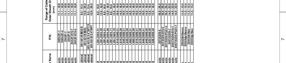
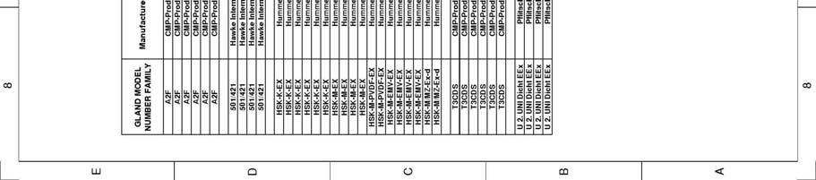
21 8 SUPPLEMENTARY INSTRUCTIONS FOR SAFE ASSEMBLY AND INSTALLATION 8.1 Use Control Drawing, Install Per Code Ensure installation is consistent with the requirements of the Control Drawing (see Annex B or C, depending on transmitter model number) and that the markings on the equipment are consistent with the classifications of the installation locations. Use cables and cable installation techniques consistent with applicable electric codes of the facility in which it is installed and/or per the guidance of EN Make Correct Terminal Block Connections Transmitter terminal block connections are as shown in Tables 2, 3, 4, and Use Cable Glands and/or Conduit Entries Cable entering the transmitter enclosure shall utilize cable glands or shall enter using conduit with appropriate conduit fittings to maintain the Zone 2 and IP55 ratings of the transmitter enclosure Selection of Cable Glands Cable glands shall be ATEX-approved for Group II or Group IIC gasses, have at least an IP55 rating, be appropriately constructed and sized for the cable and mounting hole where they are to be installed, and used in a manner consistent with the gland manufacturer s instructions. See drawing C (Annex A) for a list of recommended glands and corresponding cable size limitations Selection of Conduit Fittings Conduit entries shall be constructed and mounted such that they do not alter the type of protection and the specific characteristics of the electrical apparatus. They shall be locked into the unthreaded holes at the bottom of the transmitter or into an adaptor plate designed to be fitted in or on the bottom of the transmitter enclosure. 8.4 Wire With Power OFF All wiring operations should be performed with dead circuits C Rev 04 Page 8-1
22 8.5 Wire Securely to Terminals and Route Neatly Refer to the Process Monitoring System Installation and Startup Manual for the proper wire insulation strip length for each terminal block. The proper strip length will be long enough to guarantee that the terminal grips the bare wire and not the insulation, yet short enough to minimize the risk of shorting exposed bare wires projecting from adjacent terminals. After stripping the insulation, twist strands of stranded wire together prior to inserting into terminal so that all strands are gripped by the terminal. Securely tighten the terminal. Tug gently on wire after installation to ensure the wire is being well gripped by the terminal. Route the wire neatly in the lower portion of the transmitter and secure with wire ties to keep the wires from getting pinched when the cover closes, to keep the wires away from the circuit boards, and to keep the three groupings of wire separated from each other (mains power, incendive customer I/O, and sensor signals). Do not store excessive amounts of excess wire inside the transmitter. 8.6 No Foreign Objects Do not store tools or extraneous loose items inside the transmitter or sensor head enclosures. 8.7 Avoid Leaky Pipes Do not install the sensor band on pipes that are likely to leak. If there is doubt, perform the appropriate pipe inspections to look for evidence of an impending leak prior to installation of the sensor band. (See also paragraph 7.6.) 8.8 Seal Sensor Head Cover Ensure sensor head cover gaskets are in good condition and mate properly to each other and to the pipe. Connect all latches and properly install the clamps on the boot gaskets. 8.9 Secure The Access Panel. Use the access panel opening to access the sensor band cable connector and connect it to the preamplifier. This operation is performed after the sensor head cover is secured onto the pipe. Afterwards, securely re-install the access panel to seal that opening C Rev 04 Page 8-2
23 9 SUPPLEMENTARY INSTRUCTIONS FOR SAFELY PUTTING INTO SERVICE 9.1 Prior to Applying Power Perform a final inspection of the installation. Use the installation instructions and the Control Drawing to aid in the inspection. Verify the absence of condensation or frost inside the enclosures. Verify the customer input / output connections are made properly and are connected to remote circuits operating within the allowed ranges of voltage and current (refer to Table 3). Verify that Sensor #1 and #2 inputs (if used) are connected to passive (not active) 4-20mA transducers (reference Table 4). 9.2 Apply Power Apply power and verify a normal startup sequence as defined in the main Installation and Startup manual. If the startup sequence is abnormal, then remove power until ready to perform troubleshooting. 9.3 Perform Setup Perform the system setup procedures as defined in the main manual. 9.4 Verify Proper Operation Verify proper operation of the sonar process monitoring system and its configuration prior to using the system as a feedback element in a process control loop C Rev 04 Page 9-1
24 10 SUPPLEMENTARY INSTRUCTIONS FOR SAFE USE (NORMAL OPERATION WITH NO OPERATOR INTERVENTION) 10.1 Keep Enclosures Closed During Use Transmitter Verify the following: Sensor Head The transmitter cover should be tightly closed and all 4 screws installed to secure the cover. Cable glands should be properly installed and snug in their mounting holes in the enclosure and snug around their cables. Cables shall be prevented from applying pulling or twisting forces on the cable glands. Verify the following: All sensor head latches should be snugly mated. Clamps should be snugly installed on the boot seals. The cable connector shall be snugly latched onto the mating connector. The cable shall be installed with a drip loop (if necessary) such that water will not run along the cable toward the connector The cable shall be installed such that the connector will not be subjected to twisting or pulling forces Periodic Inspections Include the sonar process monitoring system in periodic inspections of the facility Transmitter Inspections Verify the absence of the following: Loose hardware or fittings Damage to enclosure Damage to seals Dirt or moisture inside enclosure C Rev 04 Page 10-1
25 Sensor Head Inspections Verify the absence of the following: Cables Inspections Loose or damaged latch hardware Loose or damaged boot seal clamps Damage to enclosure Damage to seals Loose or damaged access cover (including screws and seals) Loose handles Loose or damaged electrical connector or seals at the connector Evidence from the condition of the pipe that a pipe leak under the Sensor Head might occur before the next inspection (reference paragraph 7.6). Verify the absence of the following: Damaged cables Improperly installed cables (for example, cable is under tension or too tight bend radius) Loose cable management elements (strain reliefs, clamps, etc.) 10.3 Problems Found During Inspection If inspections turn up serious problems, remove the sonar process monitoring system from service until repairs can be made C Rev 04 Page 10-2
26 11 SUPPLEMENTARY INSTRUCTIONS FOR SAFE ADJUSTMENT 11.1 General Note: Making adjustments to the meter usually interrupts normal function of the meter and its outputs. If the meter is being used in a control loop, this can cause the loop to open. Inform Control Room Personnel that adjustments to the meter are going to be made to allow them to put the control loop into a manual mode of operation until adjustments are complete and the meter is ready to be brought back on line in the control loop Transmitter Adjustments Use of Keypad and RESET Switch The Zone 2 certification permits the transmitter cover to be opened for short periods of time while the power is ON for the purpose of making software configuration adjustments using the keypad or the RESET button. This is permitted without the necessity of testing first to be certain that no hazardous gasses are present. However, it is essential that when using the keypad or the RESET switch the wiring within the transmitter not be intentionally or unintentionally disturbed and that the circuitry inside the transmitter be kept clean and dry Use of USB Memory Stick Interface The USB connector is for use of a USB memory stick and is intended only for short-term infrequent use. The USB connector may only be used if the area is known to be free of explosive gas mixtures during the time immediately prior to, during, and after use of the memory stick. The USB connector is behind a tool-enabled cover. Close and secure this cover over the USB connector after use of the USB interface Use of RJ45 Ethernet Connector Interface This is a diagnostic interface and intended only for short-term infrequent use. The RJ45 Ethernet connector may only be used if the area is known to be free of explosive gas mixtures during the time immediately prior to, during, and after use of the Ethernet interface to connect to a laptop computer for diagnostic purposes C Rev 04 Page 11-1
27 Use of DB9 RS232 Connector Interface This is a diagnostic interface and intended only for short-term infrequent use. The DB9 RS232 connector may only be used if the area is known to be free of explosive gas mixtures during the time immediately prior to, during, and after use of the RS232 interface to connect to a laptop computer for diagnostic purposes Sensor Head Adjustments In normal operation there are no adjustments that need to be made at the sensor head C Rev 04 Page 11-2
28 12 SUPPLEMENTARY INSTRUCTIONS FOR SAFE MAINTENANCE, SERVICING AND EMERGENCY REPAIR 12.1 General UOS, OFF And No Explosive Gasses Present All maintenance, service, and repair should be performed with dead circuits and after testing to make sure that no explosive gas mixtures are present, unless otherwise stated (UOS) Notify Control Room Note: In most cases, servicing will interrupt normal functioning of the meter and its outputs. If the meter is being used in a control loop, this can cause the loop to open. Inform Control Room Personnel that the meter will be off-line so the control loop can be placed into a manual mode of operation until adjustments are complete and the meter is ready to be brought back on line in the control loop Transmitter General Ensure There Are No Explosive Gases Present No connection or disconnection of wiring at any of the terminal blocks in the transmitter shall be performed in the hazardous area without first testing to make sure that no explosive gas mixtures are present Keep Clean and Dry Keep the inside of the transmitter enclosure clean and dry Mains Power OFF Wiring of the mains power terminal blocks shall only be performed with the mains power wiring in a de-powered and locked-out safe state Fuse Replacement The two fuses on the power entry board are the only user serviceable fuses. They may only be replaced with the mains power wiring in a de-powered and locked-out safe state. Use only the replacement fuses indicated on the fuse warning label C Rev 04 Page 12-1
29 Sensor Terminal Blocks The Sensor Terminal blocks should be wired with the mains power OFF. This ensures that these signals are all de-powered Customer Input / Output and Fieldbus Terminal Blocks To the extent possible, ensure that the equipment on the far end of these lines is de-powered before servicing the associated terminal block connections. If unsure about whether the remote equipment is de-powered, ensure that no explosive gas mixtures are present before servicing Electrical Circuitry and Electro-Static Discharge (ESD) Take simple ESD precautions to protect the electronics such as touching a grounded metal object prior to reaching into the transmitter or sensor head enclosures and avoiding touching the circuit boards with hands, gloves, or sleeves when servicing the system Sensor Head General Ensure the inside of the sensor head cover remains clean and dry during installation and inspection Sensor Head Electrical Connector Access Panel Sensor Band Properly re-install the sensor head connector if it is removed for inspection or troubleshooting. Note: This cable connector can be removed with the power ON and without the necessity of testing first to be certain that no hazardous gasses are present. Close and latch the dust cover over the connector half that remains on the sensor head cover whenever the sensor head electrical connector on the cable is removed from the sensor head cover. Prevent contamination of the de-mated cable connector. Prior to mating the cable to the cover connector, inspect both halves to ensure they are clean and dry. Properly re-install the access panel after every time it is opened Use of Access Panel The access panel must be used to gain access to and disconnect the sensor band cable connector from the preamplifier before the sensor C Rev 04 Page 12-2
30 head cover can be removed from the pipe. Failure to do this will damage the sensor band Safety Procedure for Damaged Sensor Bands The sensor band should be removed from service and taken out of the hazardous area if it has mechanical damage. The damaged sensor band must be treated as a potentially incendive device even when it is disconnected from a power source. The damaged sensor band should not be handled in or transported through any areas where explosive gas mixtures may be present C Rev 04 Page 12-3
31 13 SUPPLEMENTARY INSTRUCTIONS FOR SAFE DISASSEMBLY OR DISPOSAL 13.1 Most Warnings Same As For Maintenance Most warnings are the same as those in Supplementary Instructions for Safe Maintenance, Servicing, and Emergency Repair, in paragraph 12, above. Additions and modifications are described below General Dead Circuits Power must be disconnected and testing performed to ensure that no explosive gas mixtures are present during disassembly and/or disposal Disposal Issues Refer to Process Monitoring System Installation and Startup Manual for disposal instructions (WEEE considerations) Sensor Band Damaged Sensor Bands The sensor band should be removed from service and taken out of the hazardous area if it has mechanical damage. The damaged sensor band must be handled as a potentially incendive device even when it is disconnected from a power source. The damaged sensor band should not be handled in or transported through any areas where explosive gas mixtures may be present Undamaged Sensor Bands Handle the band carefully to avoid damaging it (no sharp bend radii and avoid actively flexing it or allowing it to be bumped during transport). If there is any doubt about whether the sensor band might be damaged, follow the handling and transport procedures for damaged sensor bands, above. The original packing foam mandrel packing material should be used for storage. Do not store the sensor band in a hazardous area C Rev 04 Page 13-1
32 14 TRAINING Contact CiDRA Customer Support for availability and scheduling of training courses C Rev 04 Page 14-1
33 15 CONTACT INFORMATION CiDRA Corporate Services 50 Barnes Park North Wallingford, Connecticut USA Telephone numbers Toll-free in US and Canada Elsewhere Fax C Rev 04 Page 15-1
34 Annex A C, CERTIFICATION, CABLE GLAND, ZONE C Rev 04 Page A-1


35 C Rev 04 Page A-2
36 Annex B C, CONTROL DRAWING, SYSTEM, EEX, CLASS I, ZONE C Rev 04 Page B-1
37 C Rev 04 Page B-2
38 Annex C C, CONTROL DRAWING, TRANSMITTER, EEX, CLASS I, ZONE C Rev 04 Page C-1
39 C Rev 04 Page C-2
40
Additional Operating Instructions SITRANS F. Vortex flowmeters. SITRANS FX330 Ex-nA.
 Additional Operating Instructions SITRANS F Vortex flowmeters Ex-nA Edition 08/207 CONTENTS Safety instructions 3. General notes... 3.2 EU conformity... 3.3 Approval according to the IECEx scheme... 3.4
Certificate of Compliance
 FF0 001 Certificate of Compliance Certificate: 70116284 (LR 064969_0_00) Issued to: Mine Safety Appliances Company North American Division 1000 Cranberry Woods Dr Cranberry Township, Pennsylvania 16066-5296
Certificate of Compliance
 FF0 001 Certificate of Compliance Certificate: 70116279 (LR 025993_0_000) Issued to: General Monitors, Incorporated 26776 Simpatica Circle Lake Forest, California 92630 USA Attention: Larry Vlagea The
Additional Operating Instructions SITRANS F. Vortex flowmeters. SITRANS FX330 Ex-d.
 Additional Operating Instructions SITRANS F Vortex flowmeters Ex-d Edition 09/208 CONTENTS Safety instructions 3. General notes... 3.2 EU conformity... 3.3 Approval according to the IECEx scheme... 3.4
Rosemount 4500 Hygienic Pressure Transmitter. Start
 Quick Installation Guide June 2007 Rosemount 4500 Rosemount 4500 Hygienic Pressure Transmitter ProductDiscontinued Start Step 1: Mount the Transmitter Step 2: Set the Switches Step 3: Connect Wiring and
OilSET Installation and Operating Instructions. Oil Separator Alarm Device
 Labkotec Oy Myllyhaantie 6 FI-33960 PIRKKALA FINLAND Tel: +358 29 006 260 Fax: +358 29 006 1260 18.11.2010 Internet: www.labkotec.fi 1/10 OilSET-1000 Oil Separator Alarm Device Copyright 2010 Labkotec
SET-2000 Hi Level/Oil
 Labkotec Oy Labkotie 1 FI-36240 KANGASALA FINLAND Tel: + 358 29 006 260 Fax: + 358 29 006 1260 13.03.2008 Internet: www.labkotec.fi Alarm Device for Oil Separators Copyright 2008 Labkotec Oy We reserve
INSTRUCTION MANUAL (ATEX/IECEx/SIL2) BExBG05D-SIL Flameproof Xenon SIL 2 Beacons For use in Flammable Gas and Dust Atmospheres
 BExBG05D-SIL Flameproof Xenon SIL 2 Beacons For use in Flammable Gas and Dust Atmospheres") INSTRUCTION MANUAL (ATEX/IECEx/SIL2) BExBG05D-SIL Flameproof Xenon SIL 2 Beacons For use in Flammable Gas and Dust Atmospheres 1) Introduction The BExBG05D-SIL is a flameproof beacon which is certified
INSTRUCTION MANUAL (ATEX/IECEx/SIL2) BExBG05D-SIL Flameproof Xenon SIL 2 Beacons For use in Flammable Gas and Dust Atmospheres 1) Introduction The BExBG05D-SIL is a flameproof beacon which is certified
OilSET Installation and Operating Instructions. Oil Separator Alarm Device with SET/DM3AL sensor
 Labkotec UK Ltd Adminicle House 1 Lumb Lane Audenshaw Manchester M34 5WH GREAT BRITAIN Tel: 0844 3350 477 Fax: 0161 4281 179 E-mail: info@labkotec.co.uk 10.8.2012 Internet: www.labkotec.co.uk 1/13 OilSET-1000
Operating Instructions
 Operating Instructions ProVicom MT-65, MT-125 R. STAHL HMI Systems GMBH Im Gewerbegebiet Pesch 14 50767 Köln Version 1.7 Issue: 21.07.2008 R. STAHL HMI Systems GmbH / OperatingInstruction_Provicom_Falcon_en_1_7.doc
INSTRUCTION MANUAL IS-mB1 Minialite Intrinsically Safe Round LED Beacon
 INSTRUCTION MANUAL Minialite Intrinsically Safe Round LED This instruction sheet describes installations which conform to EN60079:Part14:2008 Electrical Installation in Hazardous Areas. When designing
OPTIBAR DP 7060 Supplementary Instructions
 OPTIBAR DP 7060 Supplementary Instructions Differential pressure transmitter Category ATEX II 1/2G, 2G Ex db ia IIC T6...T1 Ga/Gb, Gb IECEx Ex db ia IIC T6...T1 Ga/Gb, Gb Housing Aluminium: Single chamber,
Operating Instructions
 Important information: These instructions contain safety information, read and follow them carefully. Dialight will not accept any responsibility for injury, damage or loss which may occur due to incorrect
Model 144H. Product Data Sheet , Rev DB February Content
 Rosemount 144 PC-Programmable Temperature Transmitter Provides an installation-ready solution for temperature monitoring applications using Complete Point Solutions (CPS) Increases measurement accuracy
SET Installation and Operating Instructions. Level switch for one sensor
 Labkotec Oy Myllyhaantie 6 FI-33960 PIRKKALA FINLAND Tel.: +358 29 006 260 Fax: +358 29 006 1260 7.11.2013 Internet: www.labkotec.fi 1/14 SET-1000 Level switch for one sensor Copyright 2013 Labkotec Oy
Duct and Rough Service Carbon Monoxide Sensor
 Product Identification and Overview Duct and Rough Service Carbon Monoxide Sensor BAPI s Carbon Monoxide Sensor offers enhanced electrochemical sensing with outstanding accuracy at low concentrations.
OilSET-1000 (12 VDC)
") Labkotec Oy Myllyhaantie 6 FI-33960 PIRKKALA FINLAND Tel: +358 29 006 260 Fax: +358 29 006 1260 Internet: www.labkotec.fi 20.03.2009 1/11 OilSET-1000 (12 VDC) Oil Separator Alarm Device Copyright 2009
Labkotec Oy Myllyhaantie 6 FI-33960 PIRKKALA FINLAND Tel: +358 29 006 260 Fax: +358 29 006 1260 Internet: www.labkotec.fi 20.03.2009 1/11 OilSET-1000 (12 VDC) Oil Separator Alarm Device Copyright 2009
Annubar Flowmeter Series
 Reference Manual Appendix B Approvals Annubar Flowmeter Series Hazardous Locations Installations.................. page B-1 Rosemount 3051SFA Product Certifications.......... page B-1 Rosemount 3095MFA
INSTALLATION AND OPERATING INSTRUCTIONS R-3F2-LXX
 INSTALLATION AND OPERATING INSTRUCTIONS R-3F2-LXX UL APPROVED FOR: CLASS I, DIVISION 2 HAZ LOC CAT III & IV www.pesd.com Part Number Description: The XX specifies the fiber-o cable length in inches. General
User manual. Explosion-safe window air conditioning system Type series AR-054. II 3 G Ex ic nac h IIC T3 Gc
 User manual Explosion-safe window air conditioning system Type series AR-054 II 3 G Ex ic nac h IIC T3 Gc 1. Safety Instructions The window air conditioning series AR-054 is an explosion-safe product suitable
SAFETY MANUAL. PointWatch Eclipse Infrared Hydrocarbon Gas Detector Safety Certified Model PIRECL
 SAFETY MANUAL PointWatch Eclipse Infrared Hydrocarbon Gas Detector SIL 2 Certified Model PIRECL Safety Certified Model PIRECL PointWatch Eclipse IR Gas Detector This manual addresses the specific requirements
SET-2000 Oil/Sludge. Alarm Device for Oil Separators. Installation and Operating Instructions
 SET-000 Oil/Sludge Alarm Device for Oil Separators Copyright 007 Labkotec Oy We reserve the right for changes without notice TABLE OF CONTENTS GENERAL... INSTALLATION... 4. SET-000 Oil/Sludge Control Unit...
Carbon Monoxide Transmitter
 Introduction The CO Transmitter uses an electrochemical sensor to monitor the carbon monoxide level and outputs a field-selectable 4-20 ma or voltage signal. The voltage signal may also be set to 0-5 or
Inductive slot sensor
 0102 Model Number Features 2 mm slot width Technical Data specifications Switching function Normally closed (NC) Output type NAMUR Slot width 2 mm Depth of immersion (lateral) 5... 7 mm, typ. 6 mm Output
INSTRUCTION & SERVICE MANUAL
 INSTRUCTION & SERVICE MANUAL D2xC1 ALARM HORN AND STROBE For Use In Hazardous Locations 3) Ratings and Markings 3.1 ATEX / IECEx certification The D2xC1 Alarm Horn and Strobe complies with the following
OPTISENS TUR 2000 Technical Datasheet
 OPTISENS TUR 2000 Technical Datasheet Sensor for turbidity measurement in water and wastewater Rugged design for harsh applications Integrated transmitter with direct 4...20 ma output Near infrared light
Remote Vacuum Sensor and Variable Speed Vacuum Pump Control Manual. Version Date - June Part Number
 Innovation In and Out of Parlour Remote Vacuum Sensor and Variable Speed Vacuum Pump Control Manual Version - 1.0 Date - June 2016 Part Number - 39-0038 Index Manual Version... 3 About the Remote Vacuum
OPTIWAVE X500 Supplementary Instructions
 OPTIWAVE X500 Supplementary Instructions OPTIWAVE 3500 C OPTIWAVE 6500 C OPTIWAVE 7500 C Supplementary Instructions for ATEX applications KROHNE CONTENTS OPTIWAVE X500 1 General safety information 4 1.1
MANUAL Overflow sensor NVF-104/34-PF
 PROCESS AUTOMATION MANUAL Overflow sensor NVF-104/34-PF ISO9001 0102 Overflow sensor NVF-104/34-PF With regard to the supply of products, the current issue of the following document is applicable: The
GETTING STARTED GUIDE NI TC, ±78 mv, 24 Bit, 75 S/s Aggregate
 GETTING STARTED GUIDE NI 9213 16 TC, ±78 mv, 24 Bit, 75 S/s Aggregate This document explains how to connect to the NI 9213. Note Before you begin, complete the software and hardware installation procedures
POINTEK CLS 100 OINTEK CLS 100 CAPACITANCE LIQUIDS/SOLIDS. Instruction Manual March 2001
 POINTEK CLS 100 CAPACITANCE LIQUIDS/SOLIDS Instruction Manual March 2001 OINTEK CLS 100 Safety Guidelines Warning notices must be observed to ensure personal safety as well as that of others, and to protect
Immersion heating type IN 16.. PTB 99 ATEX 1009 U. May thuba Ltd. CH-4015 Basle Telefon Telefax
 Immersion heating type IN 16.. PTB 99 ATEX 1009 U May 1999 thuba Ltd. CH-4015 Basle Telefon +41 061 307 80 00 Telefax + 41 061 307 80 00 headoffice@thuba.com www.thuba.com Manual PTB 99 ATEX 1009U 2 Immersion
GETTING STARTED GUIDE NI Channel, 0 ma to 20 ma, 16-Bit Analog Output Module. This document explains how to connect to the NI 9265.
 GETTING STARTED GUIDE NI 9265 4-Channel, 0 ma to 20 ma, 16-Bit Analog Output Module This document explains how to connect to the NI 9265. Note Before you begin, complete the software and hardware installation
NT DUAL CHANNEL DISPLAY. User Guide
 NT DUAL CHANNEL DISPLAY User Guide Table of Contents Introduction... 2 Input Signals... 2 Output Signals... 2 User Programmable Features... 2 Installation... 3 Mechanical Installation... 3 Dimensional
DSF xx15.xx xhv Ex-Atex Ex-Atex Certified Two wire Hall Effect Speed Sensor
 DSF xx15.xx xhv Ex-Atex Product ID Type # Product # Drawing # DSF 1215.01 SHV Ex-atex (5m) 304Z-05197 113216 DSF 1415.01 AHV Ex-atex S148 304Z-05256 113351 DSF 1615.01 SHV Ex-atex (5m) 304Z-05196 113214
Model 144H. Product Data Sheet , Rev DB February Content
 Rosemount 144 PC-Programmable Temperature Transmitter Provides an installation-ready solution for temperature monitoring applications using Complete Point Solutions (CPS) Increases measurement accuracy
OPTIBAR P 1010/2010 C Supplementary instructions
 OPTIBAR P 1010/2010 C Supplementary instructions Pressure transmitter Equipment category II 1G / Ga, II 1D / Da in protection type intrinsic safety Exi KROHNE CONTENTS OPTIBAR P 1010/2010 C 1 Safety instructions
DSF xx10.xx xhv Ex-Atex Hall Effect Single Channel Speed Sensor
 Product ID Type # Product # Drawing # DSF 1210.00 SHV Ex-atex (2m) 374Z-05066 110428F1 DSF 1210.00 SHV Ex-atex (5m) 374Z-05176 110428F1 DSF 1210.00 SHV Ex-atex (10m) 374Z-05590 110428F1 DSF 1410.00 SHV
Radar Transmitters SITRANS LR400 (HART/PROFIBUS PA) Quick Start Manual 03/2013 SITRANS
 Quick Start Manual 03/2013 SITRANS") Radar Transmitters SITRANS LR400 (HART/PROFIBUS PA) Quick Start Manual 03/2013 SITRANS SITRANS LR 400 Quick Start Manual This manual outlines the essential features and functions of the SITRANS LR 400
Radar Transmitters SITRANS LR400 (HART/PROFIBUS PA) Quick Start Manual 03/2013 SITRANS SITRANS LR 400 Quick Start Manual This manual outlines the essential features and functions of the SITRANS LR 400
DL424/425 DirectLine Sensor Module for Dissolved Oxygen Probes Series DL5000 Specifications
 DL424/425 DirectLine Sensor Module for Dissolved Oxygen Probes Series DL5000 Specifications 70-82-03-48 January 2003 Overview The DirectLine DL424/425 Sensor Modules are part of a family of products developed
Compliance with EN : 2006 Electrical apparatus for explosive atmospheres Type of Protection «n» for Zone 2
 Compliance with EN60079-15: 2006 Electrical apparatus for explosive atmospheres Type of Protection «n» for Zone 2 RJ11FTVX series: rugged and sealed RJ11/12 connectors Report Prepared by : Amphenol Socapex
VERSAFLOW VORTEX Supplementary instructions
 VERSAFLOW VORTEX Supplementary instructions Vortex flowmeter Equipment category II 2G CONTENTS VERSAFLOW VORTEX 1 Safety instructions 3 1.1 General notes... 3 1.2 EC conformity... 3 1.3 Approval according
4) Intrinsic Safety Certification
 Intrinsic Safety Certification") INSTRUCTION MANUAL Minialert Intrinsically Safe Round Combined Unit Section Volume Control Tone Generator S2 S3 Tone Selection Switches Fig 1 Simplified block diagram The combined unit is CE marked for
INSTRUCTION MANUAL Minialert Intrinsically Safe Round Combined Unit Section Volume Control Tone Generator S2 S3 Tone Selection Switches Fig 1 Simplified block diagram The combined unit is CE marked for
Advance Optima Continuous Gas Analyzers AO2060-Caldos15, -Caldos17, -Magnos106, -Uras14 Category 2G Analyzer Modules
 Advance Optima Continuous Gas Analyzers AO2060-Caldos15, -Caldos17, -Magnos106, -Uras14 Category 2G Analyzer Modules Operator s Manual 42/24-12 EN Rev. 4 Contents Page Preface 4 Safety Information General
MANUAL Oil Level Sensor
 PROCESS AUTOMATION MANUAL Oil Level Sensor KVF-104-PF ISO9001 0102 With regard to the supply of products, the current issue of the following document is applicable: The General Terms of Delivery for Products
SET-2000 Oil/Sludge 12 VDC
 Labkotec Oy Myllyhaantie 6 FI-33960 PIRKKALA FINLAND Tel: + 358 29 006 260 Fax: + 358 29 006 1260 12.2.2015 Internet: www.labkotec.fi 1/14 SET-2000 Oil/Sludge 12 VDC Alarm Device for Oil Separators with
Dual Column Dehydrating Breather Manual
 Dual Column Dehydrating Breather Manual DCB-MANUAL 1.6 Read and understand this manual prior to operating or servicing the products. SPX Transformer Solutions, Inc., Service & Components Division U.S.
GETTING STARTED GUIDE NI RTD, 0 Ω to 400 Ω, 24 Bit, 400 S/s Aggregate, PT100
 GETTING STARTED GUIDE NI 9217 4 RTD, 0 Ω to 400 Ω, 24 Bit, 400 S/s Aggregate, PT100 This document explains how to connect to the NI 9217. Note Before you begin, complete the software and hardware installation
Earth-Rite II PLUS Static Earthing System
 READ MANUAL BEFORE COMMENCING WITH INSTALLATION EN Earth-Rite II PLUS Static Earthing System P1 PLUS - DC Supply Installation & Operating Instructions The safety of any system incorporating the equipment
Series DCT1000DC Dust Collector Timer Controller Specifications Installation and Operating Instructions
 Series DCT1000DC Dust Collector Timer Controller Specifications Installation and Operating Instructions Bulletin E-97DC Thank you for purchasing the Dwyer DCT1000DC Dust Collector Timer Controller. You
Certification Supplement Manual
 PROCESS ANALYSERS SERVOTOUGH FluegasExact (2700) Gas Analyser Certification Supplement Manual Part Number: 02700008D Revision: 2 Language: UK English Blank CONTENTS 1 INTRODUCTION 2 EC DECLARATION OF CONFORMITY
Fieldbus Non-Incendive Concept takes FISCO into Zone 2 and Division 2 hazardous areas. Phil Saward
 Foundation Fieldbus End Users Council Australia Inc. 9 Corcoran St Duncraig, WA 6023 P.O.Box Z5546 Perth, WA 6831 AUSTRALIA ABN 60 120 236 370 Fieldbus Non-Incendive Concept takes FISCO into Zone 2 and
Snifter ATEX22 VERSION. User Manual. Distributor
 Snifter ATEX22 VERSION User Manual Distributor Version 1.4 09/09/2009 Table of Contents 1. INTRODUCTION... 3 1.1. Safety... 3 1.2. Product overview... 4 1.3. How does it work?... 4 2. INSTALLATION... 5
PILOT VALVE ENCLOSURES FOR HAZARDOUS LOCATIONS PENTAIR CLEAN AIR SYSTEMS
 PENTAIR CLEAN AIR SYSTEMS 3-VFD COMBINATION FLAME AND DUST IGNITION PROOF ENCLOSURES Goyen pilot valve enclosures for hazardous locations are available in a combination of flame proof and dust ignition
Analog Room Pressure Monitor RPC Series
 Description The Room Pressure Monitor is used to measure differential pressure in the range of 0.125 to 1"wc or 30 to 250 Pa. It combines precision high sensitivity silicon sensing capabilities and the
REGULATIONS EUROPEAN ATEX DIRECTIVE. INTERNATIONAL SCHEME: IECEx AREAS CLASSIFICATION DEFINED BY DIRECTIVE 1999/92/EC
 EUROPEAN ATEX DIRECTIVE > European Directive 2014/34/EU ATEX Directive 2014/34/EU is a "new approach" directive that applies to protective systems against explosions as well as all equipment used in or
Intrinsically Safe Pressure Transmitters for installation in hazardous locations Models IS-20-S, IS-21-S, IS-20-F, IS-21-F WIKA Datasheet IS-20
 Electronic Pressure Measurement Intrinsically Safe Pressure Transmitters for installation in hazardous locations Models IS-20-S, IS-21-S, IS-20-F, IS-21-F WIKA Datasheet IS-20 Applications Chemical, Petrochemical
GETTING STARTED GUIDE NI DI, 30 V, Sourcing, 7 μs
 GETTING STARTED GUIDE NI 9426 32 DI, 30 V, Sourcing, 7 μs This document explains how to connect to the NI 9426. Note Before you begin, complete the software and hardware installation procedures in your
Engineering Guideline. pac- Carriers Type Universal
 Engineering Guideline pac- Carriers Type 9195 Universal Integration of conventional process automation interfaces pac- Carrier The pac- Carrier reflects the intention of R. STAHL to provide state-of-the-art
Global Series. Installation and Maintenance Instructions. Model G-STR Strobe Beacon. For Use in Hazardous Locations
 Global Series Model G-STR Strobe Beacon For Use in Hazardous Locations Ex d Surface Mount Ex de Surface Mount Installation and Maintenance Instructions 25500185 Rev. B4 1217 Printed in U.S.A. Limited Warranty
INSTRUCTION MANUAL. E2xB05 & E2xB10 Xenon Beacons For use in Hazardous Locations
 INSTRUCTION MANUAL E2xB05 & E2xB10 Xenon Beacons For use in Hazardous Locations 1) Warnings DO NOT OPEN WHEN AN EXPLOSIVE ATMOSPHERE IS PRESENT DO NOT OPEN WHEN ENERGISED POTENTIAL ELECTROSTATIC CHARGING
4-Channel Contact Closure Fiber Link Card System
 USER GUIDE RLH Industries, Inc. The leader in rugged fiber optic technology. U-020 2017A-0330 4-Channel Contact Closure Fiber Link Card System SYSTEM INSTALLATION INFORMATION Description The 4 Channel
Dräger Polytron 5100 EC Detection of toxic gases and vapors
 Dräger Polytron 5100 EC Detection of toxic gases and vapors The Dräger Polytron 5100 EC is a cost-effective explosion proof transmitter for the detection of toxic gases or oxygen. It uses a high performance
Flameproof Manual Call Points
 Operating instructions Additional languages www.r-stahl.com CS & Clifford & Snell Contents General Information.... Manufacturer.... Information regarding the operating instructions.... Further documents....
Dependable Solutions for Gas Detection
 Dependable Solutions for Gas Detection Combustibles/Flammables Standard & Exotic Toxics Oxygen Enrichment/Deficiency Introduction to Sensidyne Established in 1983 - acquired by Schauenburg GmbH in April
Installing the Cisco ONS FAP-4 Fuse Alarm Panel
 Installing the Cisco ONS 15454-FAP-4 Fuse Alarm Panel Product Number: 15454-FAP-4= This document explains how to install, test, operate, and maintain the Cisco ONS 15454-FAP-4 fuse alarm panel. This document
LC3000 Level Controller Installation and Maintenance Instructions
 4025550/12 IM-P402-36 AB Issue 12 LC3000 Level Controller Installation and Maintenance Instructions 1. General safety information LC3000 NORM ALARM TEST 2. General product information 3. Installation 4.
Immersion heating type FL65.. PTB 97 ATEX 1027 X. March thuba Ltd. CH-4015 Basle Telefon Telefax
 Immersion heating type FL65.. PTB 97 ATEX 1027 X March 1999 thuba Ltd. CH-4015 Basle Telefon +41 061 307 80 00 Telefax +41 061 307 80 10 Headoffice@thuba.com www.thuba.com Manual PTB 97 ATEX 1027 X 2 Immersion
Technical Data. General specifications. Rated operating distance s n 5 mm
 0102 Model Number Features 5 mm non-flush Usable up to SIL 2 acc. to IEC 61508 Technical Data specifications Switching function Normally closed (NC) Output type NAMUR Rated operating distance s n 5 mm
Rosemount 3490 Series
 Product Data Sheet July 2014 00813-0100-4841, Rev DA Rosemount 3490 Series 4 20 ma + HART Compatible Controller Field mounted controller with integral multi-function LCD and keypad Tough weatherproof wall
Technical Data. General specifications Switching element function Rated operating distance s n 5 mm
 0102 Model Number Features 5 mm flush Usable up to SIL 3 acc. to IEC 61508 Application Danger! In safety-related applications the sensor must be operated with a qualified fail safe interface from Pepperl+Fuchs,
Circulation heaters for ATEX/IECEx hazardous areas or in non-atex version
 for ATEX/IECEx hazardous areas or in non-atex version * Non contractual picture Warning It is imperative to read these instructions carefully before installing or maintaining the equipment. MI500EN 09/2017
Technical Data. General specifications Switching element function Rated operating distance s n 4 mm
 0102 Model Number Features 4 mm non-flush Accessories BF 12 Mounting flange, 12 mm Technical Data specifications Switching element function NAMUR, NO Rated operating distance s n 4 mm Installation non-flush
Operating & Maintenance Manual. Alert-4 Ethernet LCD Master Alarm
 Operating & Maintenance Manual Alert-4 Ethernet LCD Master Alarm w w w. a m i c o. c o m Contents User Responsibility 4 Introduction 4 Features 5 Description of the Alarm 5 Shipment Details 5 The Alarm
Schedule of Accreditation issued by United Kingdom Accreditation Service 2 Pine Trees, Chertsey Lane, Staines-upon-Thames, TW18 3HR, UK
 2 Pine Trees, Chertsey Lane, Staines-upon-Thames, TW18 3HR, UK 17065:2012 to provide product conformity certification Newport Business Park New Port Road Ellesmere Port CH65 4LZ United Kingdom Contact:
Flammable gases Detectors. Model DAX 03F DAX 03F- C DAX 03F- H. Note for installation, use and maintenance. Version 1.2
 Flammable gases Detectors Model DAX 03F DAX 03F- C DAX 03F- H Note for installation, use and maintenance Version 1.2 Introduction This handbook must be read carefully by any person who has or will have
SAFETY INFORMATION AND WARNINGS
 This manual refers to the Model SST-3 control panel manufactured since October 31, 2013, which uses a universal (100 277 VAC; 50/60 Hz) power supply. Older units use a voltage-specific power supply and
Additional Operating Instructions SITRANS F. Vortex flowmeters. SITRANS FX330 Ex-i.
 Additional Operating Instructions SITRANS F Vortex flowmeters Ex-i Edition 09/2018 CONTENTS 1 Safety instructions 3 1.1 General notes... 3 1.2 EU conformity... 3 1.3 Approval according to the IECEx scheme...
MODELS 304GC, 304GCX, 314GC, and 314GCX
 2562109A REV. A1 0317 Printed in U.S.A. MODELS 304GC, 304GCX, 314GC, and 314GCX INSTALLATION AND SERVICE INSTRUCTIONS FOR SELECTONE Limited Warranty This product is subject to and covered by a limited
SAFETY MANUAL. X2200 UV, X9800 IR, X5200 UVIR SIL 2 Certified Flame Detectors
 SAFETY MANUAL X2200 UV, X9800 IR, X5200 UVIR SIL 2 Certified Flame Detectors SAFETY-CERTIFIED Flame DETECTORs This manual addresses the specific requirements and recommendations applicable to the proper
Operating Instructions
 Important information: These instructions contain safety information, read and follow them carefully. Dialight will not accept any responsibility for injury, damage or loss which may occur due to incorrect
Manual Power relay SR853
 Manual Power relay SR853 Product types SR853.8.x.x, Rev. 1 SR853 manual page2 The symbols WARNING, CAUTION, NOTE This symbol warns of a serious hazard. Failure to observe this warning may result in death
standards: standards:
 INSTRUCTION MANUAL D2xB1LD2 LED Beacons For use in Hazardous Locations 1) Warnings DO NOT OPEN WHEN AN EXPLOSIVE ATMOSPHERE IS PRESENT DO NOT OPEN WHEN ENERGISED POTENTIAL ELECTROSTATIC CHARGING HAZARD
Two-Channel Gas Controller
 Two-Channel Gas Controller Specifications subject to change without notice. USA 09 Page of DESCRIPTION Highly configurable, UL 0 performance-tested and -certified, and wall-mounted gas monitor; continuously
RADAR LEVEL GAUGE SPECIAL SAFETY INSTRUCTION
 Special Safety Instruction en RADAR LEVEL GAUGE SPECIAL SAFETY INSTRUCTION Contents TankRadar Pro European ATEX Directive Information............................... 2 ATEX marking and Ex Certification
DB5 Intrinsically Safe Sounder Type DB-5
 Operating Instructions RTK Instruments Limited DB5 Intrinsically Safe Sounder Type DB-5 Description The DB5 Sounder is a strong, lightweight warning sounder, CENELEC certified to Ex II 1G EExia IIC T4
GETTING STARTED GUIDE NI DIO, 5 V/TTL, Bidirectional, 7 μs
 GETTING STARTED GUIDE NI 9403 32 DIO, 5 V/TTL, Bidirectional, 7 μs This document explains how to connect to the NI 9403. Note Before you begin, complete the software and hardware installation procedures
HAZARDOUS AREA CLASSIFICATION AND SELECTION OF EQUIPMENT FOR SAFE USE THEREIN FROM AN ELECTRICAL VIEWPOINT
 HAZARDOUS AREA CLASSIFICATION AND SELECTION OF EQUIPMENT FOR SAFE USE THEREIN FROM AN ELECTRICAL VIEWPOINT Olof Bekker Pr. Eng. BSc. Eng. BML S.MSAIEE, M.NACE Engineering Manager, Electrical COMMITMENT
SAFETY CERTIFIED MODEL FP-700 COMBUSTIBLE GAS DETECTOR
 SAFETY MANUAL SIL 2 Certified Model FP-700 Combustible Hydrocarbon Gas Sensor Version 2.0 1 SAFETY CERTIFIED MODEL FP-700 COMBUSTIBLE GAS DETECTOR This manual addresses the specific requirements and recommendations
INSTRUCTION MANUAL (ATEX / IECEx)
") INSTRUCTION MANUAL (ATEX / IECEx) BExS110D and BExS110D-R Sounder For use in Flammable Gas and Dust Atmospheres BExS110D BExS110D-R 1) Warnings DO NOT OPEN WHEN AN EXPLOSIVE ATMOSPHERE IS PRESENT DO NOT
INSTRUCTION MANUAL (ATEX / IECEx) BExS110D and BExS110D-R Sounder For use in Flammable Gas and Dust Atmospheres BExS110D BExS110D-R 1) Warnings DO NOT OPEN WHEN AN EXPLOSIVE ATMOSPHERE IS PRESENT DO NOT
GM420. Digital Ground Continuity Relay For AC Systems. Technical Bulletin NAE /
 3 GM20 Digital Ground Continuity Relay For AC Systems Technical Bulletin NAE03230 / 0.20 GM20 Ground continuity monitor For AC systems Description The GM20 monitors the loop resistance of ground conductors
Quick Start Guide For the
 A Leader in Level Measurement Quick Start Guide For the Universal IV Lite and Universal IV Pro Model Transmitters 2-Wire RF Admittance / Capacitance Level Measurement System with HART Protocol For Assistance
PDU Power Distribution Unit for IP-NINJAR. User s Guide Ver
 Power Distribution Unit for IP-NINJAR PDU-1209 User s Guide Ver. 1.0.0 Thank you for choosing this IDK product. To ensure the best performance of this product, please read this User s Guide fully and carefully
IECEx TEST REPORT IEC Explosive atmospheres Part 0: Equipment General requirements
 ExTR Reference Number...: ExTR Free Reference Number...: 223531 Compiled by + signature (ExTL)...: Reviewed by + signature (ExTL)...: NO/NEM/ExTR12.0018/00 Stig André Norheim Arne Hortman Date of issue...:
Duct heaters for ATEX/IECEx hazardous areas or in non-atex version
 for ATEX/IECEx hazardous areas or in non-atex version * Non contractual picture Warning It is imperative to read these instructions carefully before installing or maintaining the equipment. MI200EN 09/2017
Rosemount 248 Temperature Transmitter. Quick Start Guide , Rev. EA April 2013
 Rosemount 248 Temperature Transmitter 00825-0100-4825, Rev. EA NOTICE This installation guide provides basic guidelines for the Rosemount 248 Wireless. It does not provide instructions for detailed configuration,
WATLOW ELECTRIC MANUFACTURING COMPANY Installation & Maintenance Manual for ECO-HEAT Heaters I&M MANUAL No: Page: 1 Date: 3/15/2017 Rev: 4
 I&M MANUAL No: 316-42-76-1 Page: 1 General Statement The purpose of this product manual (the Manual ) is for Watlow Electric Manufacturing Company ( Watlow ) to convey certain recommendations, advisories,
Sentry LIQUID LEVEL ALARM MODEL 100 OPERATING MANUAL.
 Sentry LIQUID LEVEL ALARM MODEL 100 OPERATING MANUAL www.aquaticsentry.com TABLE OF CONTENTS 1. SAFETY PRECAUTIONS... 3 2. APPLICATION... 3 2.1 HIGH Liquid Level Alarm 2.2 LOW Liquid Level Alarm 3. INSTALLATION...
TraceTek Sensing Module Installation, Operation and Maintenance Instructions DESCRIPTION SPECIFICATIONS APPROVALS TYPE NM
 TTC-1 TraceTek Sensing Module Installation, Operation and Maintenance Instructions DESCRIPTION The nvent RAYCHEM TraceTek TTC-1 sensing module is used with TraceTek sensing cables to detect liquid leaks.
Fiber Optic Cable Fence Disturbance Sensor
 Architectural & Engineering Specification for Fiber Optic Cable Fence Disturbance Sensor Purpose of document This document is intended to provide performance specifications and operational requirements