APPENDIX A PROCESS CONTROL NARRATIVE
|
|
|
- Roland Boone
- 6 years ago
- Views:
Transcription
1 Town of Virden Phase 2 WWTF Upgrades MWSB#:1302 / APPENDIX A APPENDIX A PROCESS CONTROL NARRATIVE
2


3 PROCESS CONTROL NARRATIVE Town of Virden Phase 2: Wastewater Treatment Facility Upgrades January 2017
4 COPYRIGHT 2017 BY ASSOCIATED ENGINEERING (SASK.) LTD. All copyright and other intellectual property rights in these materials are reserved for the exclusive use and benefit of Associated Engineering (Sask.) Ltd. and its subsidiary companies. No part of this document may be reproduced, stored in retrieval systems or transmitted in any form or by any means, electronic, mechanical, photocopying, recording or otherwise, without the prior express written approval of Associated Engineering (Sask.) Ltd. Furthermore, this document is intended for the sole use of authorized employees of Associated Engineering (Sask.) Ltd. and its subsidiary companies in accordance with the internal policies and procedures in place and from time to time updated or adopted. Any use of this document by others is prohibited and any such use made, or any reliance made upon it or decisions made based on it, by third parties shall be at the sole responsibility of such user. Associated Engineering (Sask.) Ltd. and its subsidiary companies accepts no responsibility for loss or damages suffered by others as a result of decisions made or actions taken based on this document. Such user parties, by their use of or reliance on this document, shall be deemed to have released Associated Engineering (Sask.) Ltd. and its subsidiary companies, as well as their officers, directors, employees, agents and contractors (collective, the "Releasees") from all liability and such user parties hereby waive and release against the Releasees all recourse, claims, liabilities, damages, actions or causes of actions, of any kind whatsoever, in respect to all personal injuries, property losses or other damages or liabilities which such users or other third parties may suffer arising directly out of or connected with their use of or reliance upon this document, notwithstanding that such injuries, losses, damage or liabilities may have been related to or caused by use of or reliance upon the contents of this document.
5 PROCESS CONTROL NARRATIVE Table of Contents SECTION PAGE NO. Table of Contents i List of Tables iv List of Figures v List of Abbreviations vi Document History viii 1 Process Overview Introduction Process Narrative Overview Flow Parameters Gas Detection Flood Detection Control Structures and Vendor integration Device Naming Control Devices and Programming Equipment Types Alarms Fault Response Interlocks Trending Raw Sewage Metering and Sampling Screen Splitter Box Screens Salsnes Filter Septage System Septage Receiving Station Septage Lift Station Grit Removal System Grit Chamber Grit Pumps Grit Classifier 7-4 i
6 Town of Virden 8 Plant Lift Station Wet Wells Raw Sewage Pumps SBR System System Overview SBR Influent Splitter Box SBR Basin Equalization Tank UV System UV Disinfection Equipment UV Influent Control UV Channel Effluent Flow Monitoring and Sampling Aerobic Digestion Normal Operation Day Tank Operation Dewatering System Sludge Transfer Pumps Polymer System Screw Press Sludge Cake Screw Conveyor Blower Room Alum System Alum Tanks and Secondary Containment Area Alum Dosing Skid Plant Service Water Station Inlet Valve Operation Pressure Tank Operation Plant Service Water Pump Operation Process Water Supply as Plant Service Water Backup Power Start-up Sequence 17-1 ii \\s-wpg-fs-01\projects\ \00_virden_wwtp_ph_2\engineering\05.00_design\process narrative\pcn_wwtp_draft_ docx
7 Table of Contents Appendix A Process Flow Diagram Appendix B Helisieve Screen Control Philosophy Appendix C Salsnes Filter Control Philosophy Appendix D Grit Removal Control Philosophy Appendix E SBR and Digester Aeration Control Philosophy Appendix F UV Disinfection Control Philosophy Appendix G Dewatering System Control Philosophy Appendix H Polymer System Control Philosophy Appendix I Alum System Control Philosophy Appendix J Septage Receiving Station Control Philosophy Appendix K Naming Convention Appendix L Device Data Tables Appendix M PLC Programming Guidelines Appendix N HMI Programming Standards iii
8 Town of Virden List of Tables PAGE NO. Table 1-1 Flow Parameters 1-4 Table 1-2 Summary of SCADA System Components 1-6 Table 1-3 Summary of Virtual Alarms (Software Generated) 1-10 Table 2-1 Summary of the Equipment and Control Elements for Metering and Sampling 2-1 Table 3-1 Summary of the Equipment and Control Elements in Screen Splitter Box 3-1 Table 4-1 Summary of the Equipment and Control Elements in Screen System 4-1 Table 5-1 Summary of the Equipment and Control Elements in Filter System 5-1 Table 6-1 Septage Receiving Station s Process Units 6-1 Table 6-2 Transaction Information 6-2 Table 6-3 Septage Lift Station s Process Units 6-2 Table 7-1 Summary of the Equipment and Control Elements within Grit Removal System 7-2 Table 8-1 Summary of the Equipment and Control Elements in Plant Lift Station 8-1 Table 9-1 Summary of the Process Tanks and Super Structures within SBR Building 9-1 Table 9-2 Summary of the Equipment and Control Elements within ICEAS System 9-4 Table 10-1 Summary of the Equalization Tank Valve and Level Elements 10-1 Table 11-1 Design Effluent Water Quality 11-1 Table 11-2 UV System s Characteristics 11-2 Table 11-3 List of the Major Equipment and Control Elements of the UV System 11-2 Table 11-4 Summary of UV Influent Flow Target (m 3 /d) at Different Water Levels in EQ Tank 11-5 Table 11-5 Summary of the Equipment and Control Elements for Effluent Flow Monitoring and Sampling 11-5 Table 12-1 Summary of the Equipment and Control Elements within the Aerobic Digestion System 12-1 Table 13-1 Summary of the Equipment and Control Elements within Dewatering System 13-1 Table 13-2 Summary of Water Level Setpoints in Digester Day Tank 13-3 Table 14-1 Summary of the Equipment and Control Elements within Blower System 14-1 Table 15-1 Summary of the Equipment and Control Elements within Alum System 15-1 Table 16-1 Summary of the Equipment and Control Elements for the Plant Service Water System 16-1 iv \\s-wpg-fs-01\projects\ \00_virden_wwtp_ph_2\engineering\05.00_design\process narrative\pcn_wwtp_draft_ docx
9 List of Figures List of Figures PAGE NO. Figure 1-1 Site Orientation 1-1 Figure 9-1 Estimated Cycle Times at Normal and Storm Mode Conditions 9-3 v
10 Town of Virden List of Abbreviations The following abbreviations are used throughout the Process Control Narrative. Abbreviation AB AAF ADWF AIT BPV BUV CHV CIP CP DO EF EQ Ethernet/IP FIT HMI HOA HP KGV kpa L/s LALL LIT LSH LSHH LSL LSLL m 3 m 3 /d MCC MDF Definition Allen Bradley Average Annual Flow Average Dry Weather Flows Analyzing Indicator Transmitter Backpressure Valve Butterfly Valve Check Valve Clean-In-Place Control Panel Dissolved Oxygen Exhaust Fan Equalization Tank Ethernet Industrial Protocol Flow Indicator Transmitter Human Machine Interface Hand-Off-Auto Horse Power Knife Gate Valve Kilo Pascal Litre per second Level Alarm Low Low Level Indicator Transmitter Level Switch High Level Switch High High Level Switch Low Level Switch Low Low Cubic metre Cubic metre per day Motor Control Centre Design Maximum Day Flow vi \\s-wpg-fs-01\projects\ \00_virden_wwtp_ph_2\engineering\05.00_design\process narrative\pcn_wwtp_draft_ docx
11 List of Abbreviations Abbreviation mg/l MX NaOH PSF P&IDs PI PID PIT PIP PLC ppm PRV PSL PSW PSWP PWWF RPU SB SBR SCADA SCR TS TSL TSS UV VFD Virden WAS WWTF Definition Milligram per litre Mixer Sodium Hydroxide Parshall Flume Process and Instrumentation Diagrams Pressure Indicator Proportional Integral Derivative Pressure Indicator Transmitter Pressure Indicator Pump Programmable Logic Controllers parts per million Pressure Relief Valves Pressure Switch Low Plant Service Water Plant Service Water Pump Peak Wet Weather Flow Radio Processing Unit Splitter Box Sequencing Batch Reactor Supervisory Controls and Data Acquisition Screen Temperature Switch Temperature Switch Low Total Suspended Solids Ultraviolet Variable Frequency Drive Town of Virden Waste Activated Sludge Virden Wastewater Treatment Facility vii
12 Town of Virden Document History Document Purpose: The purpose of this document is to describe the general process control for the Virden Wastewater Treatment Facility, it will be used to aid the Integrator for programming of the facilities PLC and HMI systems. Revision History: The revision history of this document is as follows: Version Date Description Author(s) 0.1 November 2016 Document Created Kevin Yu 0.2 December 2016 Document Modified for I&C Michael Gabos viii \\s-wpg-fs-01\projects\ \00_virden_wwtp_ph_2\engineering\05.00_design\process narrative\pcn_wwtp_draft_ docx

13 PROCESS CONTROL NARRATIVE 1 Process Overview 1.1 INTRODUCTION Project Name: Town of Virden Manitoba Water Services Board Wastewater Treatment Facility Upgrades Phase 2 Location: On Third Avenue between Kent and Ashburton Streets on the South-east side of Virden, Manitoba Site Orientation: Refer to Figure 1-1. Figure 1-1 Site Orientation This process narrative discusses the Phase 2 Upgrades of the Virden Wastewater Treatment Facility (WWTF). 1-1
14 Town of Virden The Phase 1 Upgrades Headworks Project consisted of the influent wastewater metering, fine screen systems, primary treatment, and effluent chlorination/dechlorination systems upgrades and was finished in The current Headworks Building houses the metering, screen system and the primary treatment Salsnes filter. The effluent chlorination system and the dechlorinating system are reused systems from the old plant. The effluent is discharged to Gopher Creek through the outfall and ultimately ends up in the Assiniboine River. Upon completion of the Phase 1 Upgrades project, the Facility was able to achieve primary treatment flow rate of 75 L/s (6,480 m 3 /d) but had no secondary treatment capacity. The dewatered and compacted screenings are collected in a bagger unit for disposal at the landfill. The primary solids cake produced by the Salsnes Filter is of sufficient dryness that it also is disposed at the local landfill. In the Phase 2 Upgrades Project, the Virden WWTF was upgraded to provide a secondary level of treatment, biosolids stabilization, and dewatering. The upgraded facility can provide secondary treatment capacity up to 42 L/s (3,600 m 3 /d) and process a peak flow rate of 100 L/s (8,640 m 3 /d). In the Headworks Building, the existing influent metering, fine screen system, and primary treatment Salsnes Filter were retained, but a second influent forcemain, a raw sewage splitter box, and a second fine screen were added. The primary treatment Salsnes Filter was repurposed as a standby unit to facilitate plant maintenance activities. The existing old plant building was repurposed as the Main Building and expanded to accommodate additional treatment processes. The effluent chlorination system and the dechlorination system that was originally located in this building were demolished. The Main Building houses the grit removal, plant lift station, UV disinfection system, effluent Parshall flume, alum storage and dosing system, digested sludge transfer pumps, biosolids dewatering unit, biosolids storage bin, plant service water system, and a septage receiving system. A new sequencing batch reactor (SBR) secondary treatment system was built adjacent to the Headworks and Main Building. This SBR Building was constructed to include SBR reactors, equalization tanks, and aerobic digestion system. The major unit processes for the upgraded Virden WWTF are summarized as follows: Headworks Building Two influent forcemains. Influent flowmeters. Influent splitter box. Two fine screens. One Salsnes filter. Main Building Grit Removal System, including grit chamber, two grit pumps, one classifier and a grit bin. Plant Lift Station, including two wet wells and three raw sewage pumps. UV system, including influent control, UV Reactor. Parshall Flume. Sludge Dewatering System, including sludge transfer pumps, polymer system, screw press, screw conveyor and roll-off bin. Septage system, including septage receiving station, septage tank and septage transfer pumps. 1-2 \\s-wpg-fs-01\projects\ \00_virden_wwtp_ph_2\engineering\05.00_design\process narrative\pcn_wwtp_draft_ docx
15 1 - Process Overview Alum System, including dosing pump skid and two storage tanks. Plant service water station, including plant service water storage tank, two pumps and a pressure tank. SBR Building SBR Splitter box. Two (2) SBR tanks each with a fine bubble diffused aeration system, decanter, WAS pumps, and associated instruments. Two (2) Equalization Tanks. Aerobic digestion system, including two (2) aerobic digesters, one (1) digested sludge Day Tank fine bubble diffuser aeration systems, decanters and associated instruments. Blower Room with three (3) blowers for SBR tanks and two (2) blowers for aerobic digester. 1.2 PROCESS NARRATIVE OVERVIEW The following is an overview of the treatment processes at the Virden WWTP. Refer to Appendix A Process Flow Diagram. Wastewater collected in the Town of Virden is transferred to the Virden WWTP through two (2) 200 mm diameter forcemains. Each forcemain is equipped with a magnetic flow meter inside the Headworks Building. These two forcemains connect to a screen splitter box. Wastewater entering the screen splitter box is conveyed through two (2) fine screens to the grit removal system. Wastewater can also be diverted directly to the grit removal system bypassing the screens, in the event that both screens are clogged. During screen maintenance or if additional treatment is required, wastewater can have additional preliminary treatment through the Salsnes filter, which is normally on stand-by and operated manually. Grit is removed in the grit removal system which consists of a vortex grit removal chamber, two (2) grit pumps (duty/standby), and a grit classifier. Degritted water flows into the plant lift station that has two wet wells and three (3) pumps (lead/lag/standby) to convey wastewater to the SBR splitter box. Alum is dosed prior to entering the SBR tanks for phosphorus reduction. The SBR splitter box overflows into two (2) SBR tanks where the screened and degritted wastewater is treated in four main cycles; fill, react, settle and decant. Treated wastewater from each SBR is conveyed into its own equalization tank. Wastewater from the two equalization tanks flows by gravity to be disinfected in an UV reactor. The final effluent then passes through a Parshall Flume and enters the gravity outlet that discharges to the nearby Gopher Creek. The disinfected effluent can also be diverted after disinfection to the Plant Service Water (PSW) Station. The PSW station provides flushing water and wash-down water for the various unit processes within the facility (i.e., screens). Waste activated sludge from the SBRs is transferred to a two stage aerobic digester, where it is further stabilized. The digester tanks are equipped with decanters to facilitate intermittent thickening of the sludge. The supernatant is transferred by gravity to the Plant Lift Station. The stabilized sludge, or biosolids, is transferred by gravity to a day tank, and then conveyed by two (2) progressive cavity pumps (1 duty/1 standby) to the dewatering system. 1-3
16 Town of Virden The dewatering system consists of: a polymer system to help thicken sludge, a screw press which dewaters sludge, and a sludge cake conveyor, which conveys dewatered biosolids cake to a roll off bin for disposal at the local landfill. The WWTP is also capable of treating septage. There is a septage receiving station, which consists of an access control panel access for the authorized septage truck Operators, a rock trap, grinder, flowmeter storage tank, and two (2) progressive cavity pumps (1 duty/1 standby) to transfer the septage to the Plant Lift Station. The facility has a diesel generator to provide standby power for the facility, during any power outages. 1.3 FLOW PARAMETERS Table 1-1 summarizes the expected flows for 2036 for the Virden WWTF, which is the basis of design for this facility. Table 1-1 Flow Parameters Parameter Flow (m 3 /d) Design Average Annual Flow (AAF) 2,250 Design Average Dry Weather Flows (ADWF) 1,800 Design Maximum Day Flow (MDF) - Design Flow 3,600 Peak Wet Weather Flow (PWWF) - 2-hour duration 8, GAS DETECTION The headworks area, cake room, and grit room are fitted with two gas detectors, respectively: one (1) methane detector (AIT-1221, AIT-1621, AIT-1721) and one (1) H2S detector (AIT-1222, AIT-1622, AIT-1722). In the Headworks room, the ventilation system is interlocked with the lights in the room. The makeup air unit (MAU-1) and the exhaust fan (EF-1) will start whenever combustible gas is detected or the outside temperature is above 16ºC. The ventilation system will shut down upon detection of smoke or fire. In the Cake Room and Grit Room, the supply and exhaust fan will be started whenever combustible gas is detected or outside temperature is above 16ºC. The supply and exhaust fan will be shut down upon detection of smoke or fire. The ventilation system can be manually started when an Operator enters room. 1-4 \\s-wpg-fs-01\projects\ \00_virden_wwtp_ph_2\engineering\05.00_design\process narrative\pcn_wwtp_draft_ docx
17 1 - Process Overview Upon detection of elevated gas levels by either detector, a Level 1 Alarm is issued and hardwired LED strobes at the associated entry will be activated. 1.5 FLOOD DETECTION The Grit Room and Lower Equipment Room in the Main Building are equipped with one (1) capacitive type level switch (LSHH-1723, LSHH-2360), respectively: Upon detection of water levels by the detector, a Priority 1 Alarm is issued. 1.6 CONTROL STRUCTURES AND VENDOR INTEGRATION Plant instrumentation is a combination of packaged systems with localized controls and individual instrumentation components. All individual components (not part of vendor packages) will communicate with the Master Programmable Logic Controller (PLC) via discrete/analog wiring. An Ethernet based local area network will be implemented to achieve near real time monitoring and control with Rockwell Logix based PLCs; there are currently no off-site remote communications involved. Local instrumentation has indicating displays where possible. All devices connected via Ethernet (including vendor packages) will utilize heartbeat signals and timers to indicate communication integrity between the master PLC and the remote device. An Alarm will be issued if communications are lost within an Operator adjustable delay timer. The master PLC will control all data communications, and thus, perform bandwidth management between equipment throughout the site. All vendor provided packages containing PLC controllers will utilize Allen-Bradley Logix based processors. The communication protocol used will be AB Ethernet or Ethernet/IP, making available all vendor I/O to the master PLC. In the case of vendor control panels, which do not connect directly to the plant Ethernet network, all available discrete and analog I/O available will be wired directly to the nearest Master PLC for remote control. Vendors are responsible for programming PLCs and controllers that they supply and are to assist the integrator, as required, to fully incorporate the vendor packages into the master PLC system. Both the vendor and integrator are required to cooperate for commissioning and integration. Once the vendor has completed commissioning of their PLC, the integrator will import the tags and control logic into the Main PLC Program and make available all signals to the Master HMI. All vendor provided packages containing HMI screens will utilize Allen-Bradley PanelView Plus touchscreens. Similar to the PLC systems, the communication protocol used for HMI communications will be AB Ethernet or Ethernet/IP. Once the vendor has completed commissioning of their HMI, the integrator will import all available HMI screens. If screens are not available for import, it is the responsibility of the integrator to re-create the vendor screens including all functionality available locally, including the ability to remotely acknowledge and 1-5
18 Town of Virden reset vendor Alarms, as well as place the vendor system into off, manual, or remote mode. All vendor tags will be monitored, trended, and alarmed through the master SCADA system, similar to all other local tags. Vendors must adhere to the plant-wide IP scheme, using a XX.XX IP range; it is the responsibility of the vendor to configure suitable device IPs, such that there is no conflict with other network equipment within the WWTP. Vendor supplied packages each have complete control narratives for their provided products. Refer to Appendices B through K for detailed system narratives. Table 1-2 summarizes the location of the SCADA system components: Table 1-2 Summary of SCADA System Components CP/PLC Node Location Communication Description CP-1001 Headworks/Electrical Room/Screen #1 (Existing) Hardwired I/O back to master PLC CP-1201 Headworks/Electrical Room/Screen #2 Hardwired I/O back to master PLC CP-1101 Headworks/Electrical Room/Salsnes (Existing) Logix based PLC Ethernet/IP CP-1600 Main Building/Cake Room/Septage Receiving Station CompactLogix L35E PLC Ethernet/IP CP-1620 Main Building/Cake Room/Septage Receiving Grinder Hardwired I/O back to master PLC CP-1640 Main Building/Cake Room/Septage Pump 1 Hardwired I/O back to master PLC CP-1650 Main Building/Cake Room/Septage Pump 2 Hardwired I/O back to master PLC CP-1700 Main Building/Grit System Logix based PLC Ethernet/IP CP-1700B Main Building/Grit Room/ Grit Chamber Local Panel Hardwired I/O back to Grit System PLC CP-1701 Main Building/Grit Room/ Grit Mixer Local Panel Hardwired I/O back to Grit System PLC CP-2000 Main Building/Grit Room/ Grit Screw Local Panel Hardwired I/O back to Grit System PLC CP-2310 CP-2320 CP-2330 Main Building/Lower Equipment Room/ Raw Sewage Pump 1 Main Building/Lower Equipment Room/ Raw Sewage Pump 2 Main Building/Lower Equipment Room/ Raw Sewage Pump 3 Hardwired I/O back to master PLC Hardwired I/O back to master PLC Hardwired I/O back to master PLC CP-2600 SBR Building/SBR & Digester System ControlLogix L71 PLC Ethernet/IP CP-3200 Main Building/UV System CompactLogix L35E PLC Ethernet/IP CP-3800 Main Building/Process Service Water Pumps Hardwired I/O back to master PLC CP-4710 Main Building/Sludge Pump 1 Hardwired I/O back to master PLC I/O transmitted to CP-4800 via Ethernet/IP 1-6 \\s-wpg-fs-01\projects\ \00_virden_wwtp_ph_2\engineering\05.00_design\process narrative\pcn_wwtp_draft_ docx
19 1 - Process Overview CP/PLC Node Location Communication Description CP-4720 Main Building/Sludge Pump 2 Hardwired I/O back to master PLC I/O transmitted to CP-4800 via Ethernet/IP CP-4800 Main Building/Dewatering System ControlLogix L71 PLC Ethernet/IP CP-5300 Main Building/Polymer System Hardwired I/O between CP-5300 and CP Polymer pump status I/O then transmitted to master PLC via Ethernet/IP from CP-4800 CP-5500 Main Building/Alum System Hardwired I/O back to master PLC CP-0001 Main Building/Electrical Room ControlLogix L71 PLC Ethernet/IP WS1 Office Operator Workstation RSView32 View/Development Node Ethernet/IP 1.7 DEVICE NAMING Devices are named in two components, in an XXXX-#### format. The first component denotes the type of device (reference abbreviations sheets (D and D-006-0)), while the second denotes the appropriate tag number. Refer to Appendix L Naming Convention, for the naming convention. In general, the tag numbers are allocated as follows: for Headworks for Septage for Grit System (includes Grit Bin) for Plant Lift Station for SBR for Equalization Tank for UV for Plant Service Water Station for Blower Serving SBR for Blower Serving Digesters for Digestion for Dewatering for Polymer System for Sodium Hydroxide (NaOH, future) for Alum for Miscellaneous 1-7
20 Town of Virden 1.8 CONTROL DEVICES AND PROGRAMMING All PLC systems onsite, including vendor packages, will utilize Allen Bradley Logix based processors with expandable I/O. Communications between PLCs and HMIs will be either via AB Ethernet (Allen Bradley - Rockwell Automation) or Ethernet/IP (utilizing generic CIP messaging). Instrument and device controls, outside of vendor packages, will be via discrete/analog wiring back to the master PLC; these signals are identified in the top portion of the P&IDs. PLC Programming Guidelines, for general operation of devices within the WWTP, are located in Appendix M. HMI Programming Standards, for the creation of HMI screens, are located in Appendix N. Instruments will receive 120 VAC or 24 VDC power, as required, from the protected power supply feed, located within the master PLC cabinet. Motors and actuators will use 600 VAC/120VAC un-protected power directly from their designated electrical panels. PLC programming will be done with the latest version of Rockwell Automation RSLogix5000. HMI design and programming will utilize the latest version of Rockwell Automation FactoryTalk View SE, complete with automated daily, weekly, and monthly reporting. 1.9 EQUIPMENT TYPES Valves All motorized valves that are not included in vendor packaged equipment will utilize hardwired discrete/ analog signals back to the master PLC. Where I/O is not directly available from the valves actuator, a positioner will be installed to receive limit feedbacks Instruments All non-vendor supplied instruments will utilize communication protocols, as follows: Turbidity Analyzers 4-20 ma analog. Level Bulbs Discrete Conductors. Level Transmitters 4-20 ma analog. Gas Detectors 4-20 ma analog. Magnetic Flowmeters 4-20 ma analog HART. Parshall Flume 4-20 ma analog. ph Analyzers 4-20 ma analog. Pressure Transmitters 4-20 ma analog. Temperature Switch Discrete Conductors. Solenoids Discrete Conductors. 1-8 \\s-wpg-fs-01\projects\ \00_virden_wwtp_ph_2\engineering\05.00_design\process narrative\pcn_wwtp_draft_ docx
21 1 - Process Overview Motors Plant service water pumps (PSWP-3810, PSWP-3820) and digested sludge transfer pumps (SLP-4710, SLP-4720) are variable speed pumps with hardwired I/O via the variable frequency drive (VFD). Raw sewage pumps, septage transfer pumps, grit pumps, and WAS (waste activated sludge) pumps are single speed pumps with hardwired I/O, via the starter. Operator resettable run time totalizers for each motor will be programmed into the HMI; the run time will be derived from the pumps running signal ALARMS Alarms are derived from analog signals, within the PLC, logical errors, such was Valve Failure Alarms or Watchdog Alarms and directly from discrete input alarm signals. All alarms throughout the system will be monitored and handled via an external alarm dialler. An Ethernet connection between the plant PLC and the alarm dialler will be utilized for alarm annunciation. A Barnett Engineering alarm dialler will be installed within the main PLC cabinet for callout annunciations at the WWTP. Alarm logic is handled in the PLC and alarm bits are produced that trigger an HMI tag for annunciation on the Operator s workstation HMI, as well as a dial-out, if warranted. The integrator will populate and program this connection to update the callout alarm bits from the PLC, including acknowledge read back (allowing the Operator to remotely acknowledge alarms via telephone). The PLC continuously monitors plant equipment and measurements for alarm conditions. Alarms can be either digital (discrete on or off values) or analog (based on threshold values defined in the HMI). All analog signals are to have appropriate alarms derived from them. Dedicated setpoint pages will allow Operators to adjust alarm setpoints throughout the range of the associated device; PLC logic will prevent the Operator from entering a low alarm higher than a set high alarm, and vice versa. If this event occurs, a popup will be displayed indicating an incompatible value has been entered and it will revert back to its previous setpoint. All alarms, within the system, must have Operator adjustable alarm delay setpoints, giving the ability to adjust how long it takes before a true alarm is issued by the PLC. A separate alarm delay setpoint page will be made available on the Master HMI screens. The HMI must be programmed with an alarm dialer callout disable feature to localize the plant alarms to the plant only, when desired. The HMI will give the Operator the choice to automatically disable alarm callouts, when an Operator is logged in (and show callouts are disabled) or allow for manual enable/disable of callouts (HOA functionality). In Auto, the Master PLC has a time of day setpoint (Operator adjustable) that re-enables the alarm dialler callout automatically should the Operator on-call forget to re-enable the alarm dialler before leaving the plant. This feature cannot be overridden by the Operator, unless he unplugs the telephone from the alarm dialler. 1-9
22 Town of Virden Digital Alarms There are two (2) types of digital alarms used to notify Operators of an alarm condition: field generated alarms (hardwired) and software generated alarms (virtual). A field generated alarm is generated by a signal directly wired into the PLC from a field device. Possible field generated alarms could be from a hardwired float switch, a hardwired temperature switch, or a hardwired device overload signal. It should be noted that some field generated alarms from equipment, such as a pump, require that the Operator physically press the Reset button on the equipment s field mounted controls before the equipment can be restarted. Virtual alarms are generated by the PLC logic. Virtual alarms are reported when the device s current operational status does not match the status commanded by the PLC for more than a specified period of time (e.g., 30 seconds). An example of a virtual alarm is a pump fail to start alarm (Watchdog) or a valve fail alarm. If the PLC commands a pump to start and does not receive a running status ON signal from the pump within a specified period of time, a pump fail to start alarm will be generated by the PLC and displayed on the HMI. Virtual alarms must be reset by the Operator, at the HMI, before the device is able to be placed back into service and started again by the PLC. No reset is necessary at the equipment s field mounted controls as is the case for a majority of field generated alarms. Table 1-3 provides a summary of virtual alarms for all equipment types. Table 1-3 Summary of Virtual Alarms (Software Generated) Virtual Alarm Fail to Start Fail to Stop Uncommanded Start Uncommanded Stop Incorrect Position Incorrect Speed Fail to Open Fail to Close Uncommanded Open Uncommanded Close Equipment Type VS Pumps, CS Pumps, Blowers, Mixers, Generators VS Pumps, CS Pumps, Blowers, Mixers, Generators VS Pumps, CS Pumps, Blowers, Mixers, Generators VS Pumps, CS Pumps, Blowers, Mixers, Generators Modulating Valves VS Pumps Non-Modulating Valves Non-Modulating Valves Non-Modulating Valves Non-Modulating Valves 1-10 \\s-wpg-fs-01\projects\ \00_virden_wwtp_ph_2\engineering\05.00_design\process narrative\pcn_wwtp_draft_ docx
23 1 - Process Overview Analog Alarms Analog alarms are generated by the PLC to trigger a bit within the HMI; they are typically the result of a process variable being outside of the normal or expected range, as determined by the alarm setpoint entered. Typical analog alarm levels for a critical process variable are: High High (HIHI), High (HI), Low (LO), and Low Low (LOLO). The PLC contains the alarm setpoint values that are used for comparison with the process variable Alarm Display All alarms, including virtual, field generated, and analog alarms, are displayed at the HMI on both the Alarm Summary banner and the graphical representation of the equipment in alarm. The acknowledged/unacknowledged state of the alarm is indicated on both the Alarm Summary banner and the graphical representation of the equipment Remote Alarming High priority alarms require immediate Operator attention, and during non-operational hours, must be dialled out to the on-call Operator via the alarm dialler. The Operators must have the ability on the HMI to disable individual alarm callouts or all alarm callouts, at one time Other The following equipment derived alarms must be wired and made available within the PLC s alarm structure, including vendor packages containing pertinent equipment like PLCs or UPS. This includes, but is not limited to, the following: Individual 24Vdc power supply fault 24Vdc redundancy module active 120VAC UPS on-battery Generator system alarms Automatic transfer switch alarms Security system general alarm Smoke detectors Eye wash station high flow alarms Building high temperature alarms PLC general alarms Low Battery, Fault, Power Failure 1.11 FAULT RESPONSE The following guideline describes the standard fault response for communication, RPU, and equipment failures. Additional fault responses, if necessary, are described in the chapter specific to the equipment s process area. 1-11
24 Town of Virden Communication Failure In the event of a communications failure between a PLC and the HMI, the continued operation of the equipment will depend on the equipment control mode prior to the communications failure, as defined below: If the equipment was operating in REMOTE-AUTO mode prior to the communications failure, the PLC will continue to operate the equipment based on the Operator defined process setpoints. The state of the equipment can be changed if the Operator switches the equipment to LOCAL mode at the equipment s local control panel and starts/stops equipment, using field mounted controls. If the equipment was operating in REMOTE-MANUAL mode prior to the communications failure, the equipment will revert to REMOTE-AUTO mode upon loss of communication continuing operation, using the last known setpoints. If the equipment was operating in LOCAL-MANUAL mode, it is the Operator s responsibility to manually operate this device or place it back into REMOTE-AUTO or it will not function via PLC control. When running in LOCAL-MANUAL mode, the device will continue operating in its current state (running/stopped) until a hard-wired interlock stops the equipment. An alarm will be displayed at the HMI, indicating the failed communications link Equipment Failure In the event of a plant power failure, the SCADA will store the active setpoints and duty statuses, allowing the Operator to restart the plant with the prior configuration. Any failed equipment will issue an alarm. In most cases, level transmitters will defer operation of designated pumps to associated float bulbs. Vendor package control panels that lose communication with their parent PLC will trigger a communication alarm, and continue to operate locally, if possible. In the event of a level transmitter failure, the PLC will force the level sensor value to 0 (empty well reading) and a transmitter failure alarm will be displayed at the HMI. All other transmitter failures will result in an alarm being displayed at the HMI. The transmitter will need to be inspected and repaired. An actuator fault can be a jam, electrical fault, or loss of communication. In motors, additional faults are overcurrent, leakage, over-speed, and/or vibration \\s-wpg-fs-01\projects\ \00_virden_wwtp_ph_2\engineering\05.00_design\process narrative\pcn_wwtp_draft_ docx
25 1 - Process Overview Most actuators (particularly gate actuators) are configured to remain in their current position in the event of a fault. In most cases this will allow the current duty device to continue operating, while giving the Operator enough time to attend to the faulted actuator, and shut down the related process equipment, if necessary. In many cases, this means gates are failing to the open position. By failing to the open position, gates are less likely to cause upstream flooding under normal flow conditions. However, if pipes are damaged or clogged, preventing proper flow, flooding may occur in the event of a fault INTERLOCKS Safety interlocks are designed to prevent damage to equipment and injury to plant personnel. Hard-wired interlocks, such as high temperatures and pump overloads will stop the equipment and prevent it from running, until the alarm condition has been reset in the field. Software (PLC generated) interlocks, such as pump watchdogs or valve failure alarms, must be reset by the Operator at the HMI, before the equipment is allowed to be operated again in any REMOTE mode. Any alarm listed in this document s alarm tables, containing a reset location of Field, indicates it is a hardwired interlock, while any alarm with a reset location of SCADA, indicates it is a software interlock TRENDING Trends displaying process information over an Operator selectable period of time (e.g., 3, 6, 12, or 24 hours) for all plant instrumentation are accessible to the Operator via the Master HMI screens. Trend screens allow the Operator to view Historical data up to the past 400 days. 1-13
26
27 PROCESS CONTROL NARRATIVE 2 Raw Sewage Metering and Sampling Headworks building mainly contains the following major process equipment: One (1) Screen Splitter Box, SB-1200; Two (2) Helisieve screens, SCR-1001 and SCR-1201; and One (1) Salsnes Filter System, FIL Raw wastewater is pumped into the Screen Splitter Box (SB-1200) via two (2) 200 mm diameter forcemains from two (2) lift stations in the Town. Flows are measured and recorded respectively by the two (2) magnetic flowmeters installed on the two (2) forcemains, which were tagged as FE-1001 and FE Table 2-1 shows the flow range for the two (2) flow meters and summarizes the major process equipment and associated control elements within the Raw Sewage Metering and Sampling System. Table 2-1 Summary of the Equipment and Control Elements for Metering and Sampling Equipment / Instrument / Control Valve Tag Comments Flow Meter for Inflow Line #1 FIT mm, 0-70 L/s Flow Meter for Inflow Line #2 FIT mm, 0-70 L/s Automatic Composite Sampler #1 SMP-1001 Connecting to Screen Splitter Box - Inlet solenoid valve (existing) SNV-1005 Normally Closed - Sampling line isolation Valve BAV-1005 Manual, Normally Open The Headworks has one (1) automatic composite sampler analyzer (SMP-1001), which is connected with the Screen Splitter Box via a sample line to take raw sewage samples. A sampling action is performed through a normally closed solenoid valve. When a sample cycle starts, the solenoid valve will open. Following completion of a successful sample cycle, the sampler will emit a 4 second 15 VDC pulse. If the pulse has not been received for a period of time equal to one hour, a General Alarm will be issued. Wastewater sampling will either be proportional to the total plant inflow combined reading from FIT-1201 and FIT-1001 or at an adjustable time interval. 2-1
28
29 PROCESS CONTROL NARRATIVE 3 Screen Splitter Box The purpose of the Screen Splitter Box (SB-1200) is to combine the two inflows from the lift stations outside of the WWTP and the flow from the Headworks sump and then distribute the combined sewage to the two (2) Helisieve Screens, via two (2) 250 mm diameter outlet nozzles. Each incoming line can be isolated from SB-1200 (KGV-1001, KGV-1201). The Screen Splitter Box also has an overflow to allow wastewater to bypass around the Helisieve Screens in the event that both screens are clogged or off-line. The overflow can be directed to either the grit system or the Salsnes Filter by adjusting downstream valves (KGV-1002, KGV-1003). The level switch (LSH-1201), installed in the Screen Splitter Box (SB-1200), will generate an Alarm when the water level inside the Screen Splitter Box reaches the overflow setpoint of xxx.xxx m to indicate a bypass event is occurring. Table 3-1 summarizes the major process equipment and associated control elements within the Screen Splitter Box. Table 3-1 Summary of the Equipment and Control Elements in Screen Splitter Box Equipment / Instrument / Control Valve Tag Comments Screen Splitter Box SB Level Switch High LSH-1201 Level 2 Alarm - Line#1 Inlet Isolation Valve (existing) KGV-1001 Manual, Normally Open - Line #2 Inlet Isolation Valve KGV-1201 Manual, Normally Open 3-1
30
31 PROCESS CONTROL NARRATIVE 4 Screens The screen system consists of two mechanical fine screens (SCR-1001, SCR-1201). The screens are Helisieve units with identical capacity and both operate in DUTY mode, under normal conditions. Each screen can be isolated manually, using the knife gate valves upstream and downstream of the screen (KGV-1007, KGV-1011, KGV-1207, KGV-1211). Table 4-1 summarizes the major process equipment and associated control elements within the Screens. Table 4-1 Summary of the Equipment and Control Elements in Screen System Equipment / Instrument / Control Valve Tag Comments Helisieve Screen #1 SCR-1001 Duty - Level Indicator (existing) LIT Spray Wash System Solenoid Valve (existing) SNV Inlet Isolation Valve KGV-1007 Manual, Normally Open - Effluent Isolation Valve KGV-1011 Manual, Normally Open - Screenings Bin BIN Helisieve Screen #1 Control Panel CP-1000 Helisieve Screen #2 SCR-1201 Duty - Level Indicator LIT Spray Wash System Solenoid Valve SNV Inlet Isolation Valve KGV-1207 Manual, Normally Open - Effluent Isolation Valve KGV-1211 Manual, Normally Open - Screenings Bin BIN Helisieve Screen #2 Control Panel CP-1200 A Helisieve Screen unit consists of a spiral assembly, screen basket assembly, transport tube assembly, press zone assembly, discharge assembly, drive system, tank assembly with integral bypass, and controls. Each screen has its own control panel (CP-1000, CP-1200) that will control the operation of the screen, and start and stop signals will be available for remote control of the units. All available status feedback and alarm signals will be sent to the master PLC and displayed on the HMI. 4-1
32 Town of Virden Under normal operation, influent is directed to the internal surface of the screen basket, where the larger solids will be retained. The motorized spiral will transport the solids up the screen basket through the transport tube and into the press zone, where they will be dewatered. The dewatered solids will then be discharged to a screenings bin. In the event of screen blinding or mechanical failure, the flow will enter the bypass chamber over an adjustable weir. The bypass bar rack, located in the tank assembly, can temporarily function as a manual screen to retain larger solids, but Operator intervention is required immediately. The level indicator, LIT- 1001, installed in SCR-1001, and the level indicator, LIT-1201, in SCR-1201, will generate a High Level Alarm, when the water level inside the screen reaches the pre-set overflow setpoint to indicate a bypass event is occurring. A Helisieve Screen runs either via the level sensor (LIT-1001, LIT-1201) installed before the screen, or via a repeat cycle timer, initially set for 60 minutes off time (first) and 15 seconds on time. The off timer will reset, if the unit runs based off of the level sensor or is manually operated. Upon loss of the run signal, the unit will continue to run for the length of time set on the off delay timer, initially set at 30 seconds. The spray wash system in the press zone is used to flush screenings residue from the press zone. The spray wash system consists of a radial spray header and solenoid valve (SNV-1001 in SCR-1001 and SNV in SCR-1201). The spray wash system will operate independently via a repeat cycle timer (i.e., 15 seconds on, followed by 30 minutes off). When one of the two Helisieve Screens need to be taken out for maintenance, the procedures below will be followed: Manual isolation valves upstream and downstream of the spiral screen are closed (KGV-1007 and KGV-1011 or KGV-1207 and KGV-1211). Screen is placed in LOCAL mode at the Vendor s control panel (CP-1000, CP-1200). The local disconnect switch is adjusted to the OFF position. Complete maintenance on the screen. Once finished, the manual valves upstream and downstream of the spiral screen are opened. The local disconnect switch adjusted to the ON position. Spiral screen is put back into REMOTE-AUTO mode at the Vendor s PLC. In the event of both fine screens being taken off-line, influent flows can overflow directly to the grit removal system, bypassing the screens. Refer to the vendor-provided document in Appendix B - Helisieve Screen Control Philosophy for information on the system s operational strategy. 4-2 \\s-wpg-fs-01\projects\ \00_virden_wwtp_ph_2\engineering\05.00_design\process narrative\pcn_wwtp_draft_ docx
33 PROCESS CONTROL NARRATIVE 5 Salsnes Filter The Salsnes Filter System is capable of performing solid separation, primary sludge thickening, and dewatering. Wastewater enters the system inlet well and is then filtered through a rotating filter belt. Filtered effluent leaves the system by gravity and is sent to the grit removal system for further treatment. An air knife automatic cleaning system uses air to clean the filter mesh. The solids drop onto the screw press for thickening and pressing and is then discharged into a bin. Hot water is used for the filter belt flushing at a pre-set time interval. Table 5-1 summarizes the major process equipment and associated control elements within the Salsnes Filter. Table 5-1 Summary of the Equipment and Control Elements in Filter System Equipment / Instrument / Control Valve Tag Comments Salsnes Filter FIL-1101 Normally on Standby - Inlet Valve KGV-1002 Manual, Normally Closed - Bypass Valve KGV-1003 Manual, Normally Open - Level Indicator LIT Hot Water Solenoid Valve NEV Hot Water Pressure Switch Low PSL-1101 Level 2 Alarm - Hot Water Temperature Switch Low TSL-1101 Level 2 Alarm - Cold Water Solenoid Valve NEV Cold Water 4-way Solenoid Valve TWV Drain Valve GAV-1101 Filter Air Blower BLO Cooling Fan FN Pressure Indicator PIT-1101 Level 2 Alarm - Filter Sludge Screw SCP Bin BIN Salsnes Control Panel CP
34 Town of Virden The Salsnes System has its own control panel (CP-1100) that will control the operation of the unit, but status and alarms will be sent to the Main Plant PLC and displayed on the HMI. The Salsnes Filter System functions as a backup primary treatment process. Normally, the system is in standby status and only runs when the plant needs the pre-treatment process, due to deteriorated water quality or if the screens are offline for maintenance. During standby period, the motorized inlet valve, KGV-1002, is normally closed and the bypass valve, KGV-1003, is open. In the case that the WWTP needs to bring the Salsnes Filter online, the motorized inlet valve, KGV-1002, is opened first and then the motorized bypass valve, KGV-1003, is closed. By doing so, the screened wastewater is directed to the Salsnes Filter. Both the Filter Belt and Sludge Screw have a variable frequency drive (VFD), and the speed of the motors will be varied to maintain the water level of the filter inlet well. When the water level inside the inlet well is below a setpoint, the Filter Belt and Sludge Screw stop. If the inlet well water level is above an overflow setting level, the filter system overflow occurs. The existing Salsnes Filter has an Allen-Bradley Logix based PLC, which controls the operation of the Filter Belt and Sludge Screw; it communicates all available I/O with the master PLC via Ethernet. Refer to the vendor-provided document in Appendix C - Salsnes Filter Control Philosophy for information on the system s operational strategy. 5-2 \\s-wpg-fs-01\projects\ \00_virden_wwtp_ph_2\engineering\05.00_design\process narrative\pcn_wwtp_draft_ docx
35 PROCESS CONTROL NARRATIVE 6 Septage System 6.1 SEPTAGE RECEIVING STATION The Septage Receiving Station serves as a terminal to collect and pre-process septage for the grit removal, SBR, and sludge digester processes. Septage flows from the user s haul tanker by gravity through the septage station and into the WWTP s septage tank (TK-1630). The main equipment are the mechanical units shown in Table 6-1. Table 6-1 Septage Receiving Station s Process Units Process Units Tag # Functions Motorized Plug Valve PLV-1611 Automated: Start/Stop septage intake Rock Trap RT-1610 Remove heavy mineral solids to protect the grinder Grinder GRD-1620 Comminute solids in the septage Grinder Control Panel CP-1620 Septage Flowmeter FE-1601 Communicate flowrate and total volume to the station Access Station Septage Receiving Station Control Panel CP-1600 The plug valve (PLV-1611) is connected to a union that users can connect to from their haul tank s discharge, and it can be opened or closed by the septage station s controller, using a motorized actuator. The rock trap (RT-1610) is installed before the grinder (GRD-1620) for equipment protection because hard mineral solids may shorten the service life of grinder equipment. The grinder is the main process unit and provides a fault signal back to the master PLC; it reduces the septage solid materials sizes to mitigate plugging of downstream equipment or piping. The grinder can handle flow rates up to L/s and pressure up to 90 psi. Operating flow rates vary and depend on the height of the user s septage hauler tank. Lastly, the flowmeter communicates the flow rates and the total offloaded volume of septage to the system s controller. In addition to the mechanical components, a septate receiving user interface panel is installed near the unloading connection, allowing interaction between the haul tanker and the septage unloading system. First, the user is prompted to login by entering a passcode and/or swiping a magnetic strip containing a proxy ID (as per vendor standard). Upon successful login, they begin the transaction by pressing Start on the user interface panel. The controller commences the process by opening the valve (PLV-1611) and starting the grinder (GRD-1620). During septage offload, the controller s software tracks the septage flow rates and the total volume offloaded by the user. During a transaction, the user may terminate the process by pressing Stop on the 6-1
36 Town of Virden user interface panel. The controller is also capable of ending the process, when the septage tank level switch, LSH-1632, is triggered or there are no flows for a predetermined time. For each transaction, the information, shown in Table 6-2, is communicated to the station s controller. The information may be printed in a receipt or display on the HMI. The SCADA system also stores the information to better understand and optimize the WWTP s septage receiving procedures. Date and Time of Transaction: Septage Receiving Station ID: Hauler s User ID: Volume Offloaded: Elapsed Time: Waste Type: Capacity Balance: Table 6-2 Transaction Information Process Units 6.2 SEPTAGE LIFT STATION The Septage Lift Station has two (2) progressive cavity pumps (SEP-1640 and SEP-1650, duty/standby), located in the Main Building s basement, which are used to transfer septage from the Septage Tank (TK-1630) to the grit tank (GCB-1700). Each pump has a capacity of 2.8 L/s. The duty pump is to be selected by the Operator from the HMI. The flow is monitored by FIT Level Indicator Table 6-3 Septage Lift Station s Process Units Process Units Tag # Functions LIT-1631 Level Switch Low LSL-1631 Stop the septage pump Level Switch High LSH-1632 Level 1 Alarm, indicating the tank is full, to stop receiving septage Septage Pump #1 Pressure Switch Low SEP-1640 PSL-1641 Pressure Switch High PSH-1642 Level 1 Alarm Temperature Switch TS-1640 Level 1 Alarm 6-2 \\s-wpg-fs-01\projects\ \00_virden_wwtp_ph_2\engineering\05.00_design\process narrative\pcn_wwtp_draft_ docx
37 6 - Septage System Process Units Tag # Functions Septage Pump #2 SEP-1650 Pressure Switch Low PSL-1651 Pressure Switch High PSH-1652 Level 1 Alarm Temperature Switch TS-1650 Level 1 Alarm Flow meter FIT-1641 Pressure switches and temperature switches were installed to protect the septage pumps from dry-running or overloading, including: Pressure switch low on suction line for each pump (PSL-1641 and PSL-1651) is to Stop the pump, when the suction line is less than the low pressure setpoint of 0 kpa. Pressure indicator on discharge line for each pump (PIT-1642 and PIT-1652) is to Stop the pump, when the discharge line pressure is higher than the high pressure setpoint of 350 kpa Temperature switch integrated into each pump (TS-1640 and TS-1650) is to Stop the pump, when the temperature in the pump is higher than the high temperature setpoint of xxx degree. Septage normally has high TSS and organic concentrations and should not be continuously fed to the WWTP, in a short period of time. The control strategy is to feed septage with a certain volume on an hourly basis to avoid upsetting the biological process units in the WWTP. During normal septage feeding operation, the duty septage transfer pump will be turned On once per hour and run for 5-10 minutes (Tf) until a pre-set volume (Vs) is reached. The feeding volume is measured by the flowmeter, FIT The pre-set volume (Vs) can be calculated, based on the following parameters: Maximum septage feeding volume per day (m 3 /d), Qd, which will not exceed 10% of the current plant s average daily flow. Feeding hours per day (hr), Th, which can be adjusted between 12 to 24. Pre-set volume Vs = Qd / Th. The pump running time Tf (min) will be checked to make sure the Tf is not less than 5 minutes for pump protection. Refer to the vendor-provided document, Appendix J Septage Receiving Station Control Philosophy, for more details on the operation of the Septage Receiving Station System. 6-3
38
39 PROCESS CONTROL NARRATIVE 7 Grit Removal System The Grit Removal System is designed to remove grit from screened sewage at a peak design flow of 8,640 m 3 /d. The grit system also receives flow from the septage receiving system and filtrate from the dewatering system. The septage has been through a rock trap and processed through a grinder. The grit removal system is designed to allow for a grit removal efficiency as follows: 96% for grit larger than 300-microns diameter in size. 87% for grit larger than 210-microns diameter and less than 300-microns in size. 75% for grit larger than 150-microns diameter and less than 210-microns in size. 68% for grit larger than 100-microns diameter and less than 150-microns in size. The grit system consists of three major components: grit chamber, two (2) grit pumps, and a grit classifier with a hydrocyclone concentrator. In the event that grit system is taken off-line, influent flow can be directed into the Plant Lift Station via a bypass line and pumped to the SBRs directly. The grit accumulates in the grit chamber and a duty grit pump (GTP-1910 or GTP-1920) will periodically discharge the grit slurry into the hydrocyclone for dewatering. The supernatant from the hydrocyclone is discharge by gravity to the Plant Lift Station. The concentrated solids pass into the grit classifier (GCL- 2000) where the grit is settled, dewatered, and transferred to a grit storage bin (BIN-2000) for disposal. The supernatant from the classifier is also transferred by gravity to the Plant Lift Station. The two (2) grit pumps are installed adjacent to the grit chamber, but located in the Lower Equipment Room, which is a non-classified area. The hydrocyclone and grit classifier are located in Cake Room, where the dewatered grit is discharged into a grit bin (BIN-2000) and trucked out. The Grit and Cake Rooms are classified as Class I, Division 1. The Grit System has a dedicated control panel that will operate this system (mixer, water scour, and grit pumps); all available status and alarms will be sent to the master PLC and displayed on the HMI. Table 7-1 summarizes the major process equipment and associated control elements within the Grit Removal System. 7-1
40 Town of Virden Table 7-1 Summary of the Equipment and Control Elements within Grit Removal System Equipment / Instrument / Control Valve Tag Comments Grit Chamber GCB-1700 Bypass valve w/actuator KGV-1702 Not included in Grit Package / Automated, Normally Closed Inlet Isolation Valve KGV-1701 Manual, Normally Open Outlet Isolation Valve KGV-1703 Manual, Normally Open Paddle mixer Level indicator transmitter Fluidization system solenoid valve MX-1701 LIT-1701 SNV-1701 Fluidization Inlet Isolation Valve #1 BAV-1701 Manual, Normally Open Fluidization Inlet Isolation Valve #2 BAV-1702 Manual, Normally Open Fluidization Strainer Grit Pump #1 STR-1701 GTP-1910 Inlet valve PLV-1910 Manual, Normally Open Outlet valve PLV-1912 Manual, Normally Open Outlet pressure gauge w/ annular seal PI-1911 Not included in Grit Package Ball Check Valve (not necessary if grit pump comes with internal check valve) Grit Pump #2 BCV-1910 GTP-1920 Not included in Grit Package Inlet valve PLV-1920 Manual, Normally Open Outlet valve PLV-1922 Manual, Normally Open Outlet pressure gauge w/ annular seal PI-1921 Not included in Grit Package Ball Check Valve (not necessary if grit pump comes with internal check valve) BCV-1920 Not included in Grit Package Grit Classifier GCL-2000 Hydrocyclone and classifier Grit System Control Panel Grit Pump Control Panel CP-1700 CP \\s-wpg-fs-01\projects\ \00_virden_wwtp_ph_2\engineering\05.00_design\process narrative\pcn_wwtp_draft_ docx
41 7 - Grit Removal System 7.1 GRIT CHAMBER The Grit Chamber (GCB-1700) is located in the Grit Room, in the Main Building. The Grit Room extends from the basement floor up to the ceiling and is physically separated from other non-classified rooms in the Main Building. It is classified as Class I, Division 1. The grit chamber is equipped with a paddle type mixer (MX-1701), which is rotating continuously at a preset speed (adjustable in Grit System Control Panel CP-1700) in order to maintain the rotation water flow regime for maximizing grit removal efficiency. The vertical location of the paddle mixer can be adjusted. Three knife gate valves are installed before and after the grit chamber to determine operating or bypassing mode of the grit chamber. Among the three valves, the inlet and outlet valves (KGV-1701 and KGV-1703) are manual, and the bypass valve (KGV-1702) is electrical. Under normal operation, the manual inlet valve (KGV-1701) and the outlet valve (KGV-1703) are open and the bypass valve (KGV-1702) is closed. Screened influent discharge is directed to the vortex grit chamber through the inlet valve (KGV-1701), on the 400 mm diameter inlet line, and leaves the grit chamber through the outlet valve (KGV-1703) to the Plant Lift Station wet wells. When the water level inside reaches the overflow Water Level High setpoint of m, an Alarm will be generated to notify the Operator of a High Water Level Event. Operator will check the cause of the Water Level High Alarm and act at their discretion. When the water level inside reaches the Overflow Water Level High-High setpoint of m, the bypass valve (KGV-1702) will be automatically open to allow excess flow to be bypassed. A Level 1 Alarm will be generated to prompt the Operator to solve the Water Level High-High Issue. The grit removal system can also be intentionally bypassed by manually shutting off the inlet valve (KGV- 1701) and the outlet valve (KGV-1703) and opening the bypass valve (KGV-1702). This will allow the water to flow directly into the Plant Lift Station; bypassing the grit removal system, if it needs to be closed for maintenance. The grit chamber is provided with a fluidisation system, which is at the bottom of the grit chamber. The purpose of the fluidisation system is to scour the grit settlement in the grit chamber hopper before the duty grit pump starts extracting grit to the grit classifier. Grit chamber fluidisation is provided by opening a solenoid valve (SNV-1701) for scouring water that is controlled by CP The fluidisation system will remain active for the complete duration of the grit extraction cycle. 7-3
42 Town of Virden 7.2 GRIT PUMPS Two non-clog impeller type grit pumps (GTP-1910 and GTP-1920) are required to remove accumulated grit from the grit tank. These pumps operate as duty/standby; the duty status is assigned by the Grit System control panel (CP-1700). The inlet and the outlet of the pumps are controlled be manual plug valves, which can be used to isolate the pumps during pump maintenance. Under normal auto operation, the grit pumping cycles (extraction sequences) are initiated by an automatic time setpoint (adjustable). When the sequence begins, the water scouring valve (SNV-1701) opens and the duty grit pump operates for a pre-determined period of time. At the end of the pre-determined period of time for the duty grit pump operation, the Grit System Control Panel (CP-1700) will close the scouring valve and shut-off the duty grit pump. 7.3 GRIT CLASSIFIER The purpose of the hydrocyclone and grit classifier is to concentrate the grit and return the organic portion of the wastewater to the main treatment process for further treatment. The grit and wastewater mixture from the grit pump flows through the hydrocyclone, where the slurry stream is concentrated prior to it entering the classifier. The concentrated grit stream then enters the classifier hopper for settling. The grit classifier has an inclined spiral screw conveyor that removes the collected grit from the hopper and further dewaters the grit as it conveys it to the discharge chute. The grit is dropped into a grit bin (BIN-2000), which is later trucked away. The screw conveyor motor is wired to the starter located in the dewatering system s control panel; the panel provides local indication lights, in addition to HOA controls for the conveyor. All conveyor operations are controlled by the dewatering system s PLC, using the following signals: Start Forward, Start Reverse, Running Forward, Running Reverse, Fault and Zero Speed Switch indication. Wastewater from the hydrocyclone and the classifier hopper overflow is discharged into the Plant Lift Station wet wells by gravity for further treatment. Under normal auto operation, the grit classifier starts with the grit pumping cycles (extraction sequences). The classifier runs as long as the start signal is maintained by the outside source, then continues to run for a pre-set duration after the extraction sequence ends. The grit system control panel (CP-1700) controls the operation of the grit classifier. Refer to the vendor-provided document, Appendix D - Grit Removal Control Philosophy, for a detailed functional description of the screenings equipment, alarms, controls, and manual operation. 7-4 \\s-wpg-fs-01\projects\ \00_virden_wwtp_ph_2\engineering\05.00_design\process narrative\pcn_wwtp_draft_ docx
43 PROCESS CONTROL NARRATIVE 8 Plant Lift Station The Plant Lift Station contains two wet wells (T-2200 and T-2300) and three centrifugal type raw sewage pumps (RWP-2310, RWP-2320, and RWP-2330 [lead/lag/standby]). The maximum pumping capacity of the Plant Lift Station is 8,640 m 3 /d. The main purpose of the Plant Lift Station is to transfer screened and degritted wastewater from the wet wells to SBR system. In addition, the Plant Lift Station receives and conveys other sewage inflows to the SBR, including: Dewatering Room: Dewatering area floor drains, filtrate from the Screw Press, Cake Room floor drains, overflow from the grit classifier, and supernatant from the hydrocyclone. Supernatant from the digesters. Sanitary from the Locker Rooms, Office, Laboratory and local low pressure collection system. Table 8-1 summarizes the major process equipment and associated control elements for the Plant Lift Station. Table 8-1 Summary of the Equipment and Control Elements in Plant Lift Station Equipment / Instrument / Control Valve Tag Comments Wet Well #1 T Level Indicator LIT Grit System Effluent Isolation Valve KGV-2201 Manual, Normally Open - Digester Decant Isolation Valve KGV-2202 Manual, Normally Open - Dewatering Room Isolation Valve KGV-2203 Manual, Normally Open - Wet Well 1 Outlet Isolation Valve KGV-2206 Manual, Normally Open - Outlet Valve Limit Switch ZSH-2206 Valve Position Indicator Wet Well #2 T Level Indicator LIT Level Switch Low Low LSLL-2301 All Pump Stop - Level Switch Low LSL-2302 Start Duty Pump 1 - Level Switch High LSH-2303 Start Duty Pump 2 - Level Switch High High LSHH-2304 Trigger overflow alarm (Level 1) - Grit System Effluent Isolation Valve KGV-2301 Manual, Normally Open - Digester Decant Isolation Valve KGV-2302 Manual, Normally Open - Dewatering Room Isolation Valve KGV-2303 Manual, Normally Open 8-1
44 Town of Virden Equipment / Instrument / Control Valve Tag Comments - Wet Well 2 Outlet Isolation Valve KGV-2306 Manual, Normally Open - Outlet Valve Limit Switch ZSH-2306 Valve position indicator Raw Sewage Pump #1 RWP Pressure Gauge PI Pump #1 Inlet Isolation Valve KGV-2311 Manual, Normally Open - Pump #1 Discharge Isolation Valve KGV-2312 Manual, Normally Open - Pump #1 Check Valve CHV Pump #1 Inlet Drain Valve BAV-2313 Manual, Normally Closed - Pump #1 Discharge Drain Valve BAV-2314 Manual, Normally Closed Raw Sewage Pump #2 RWP Pressure Gauge PI Pump #2 Inlet Isolation Valve KGV-2321 Manual, Normally Open - Pump #2 Discharge Isolation Valve KGV-2322 Manual, Normally Open - Pump #2 Check Valve CHV Pump #2 Inlet Drain Valve BAV-2323 Manual, Normally Closed - Pump #2 Discharge Drain Valve BAV-2324 Manual, Normally Closed Raw Sewage Pump #3 RWP Pressure Gauge PI Pump #3 Inlet Isolation Valve KGV-2321 Manual, Normally Open - Pump #3 Discharge Isolation Valve KGV-2322 Manual, Normally Open - Pump #3 Check Valve CHV Pump #3 Inlet Drain Valve BAV-2323 Manual, Normally Closed - Pump #3 Discharge Drain Valve BAV-2324 Manual, Normally Closed Plant Lift Station Flow Indicator FIT-2352 Plant Lift Station Discharge Pipe Drain BAV-2351 Manual, Normally Closed Plant Lift Station Air Release Valve ARV-2351 Air Release Isolation Valve PLV-2351 Manual, Normally Open Alum Injection Quill Isolation Valve BAV-5585 Manual, Normally Open Alum Injection Back Pressure Valve BPV \\s-wpg-fs-01\projects\ \00_virden_wwtp_ph_2\engineering\05.00_design\process narrative\pcn_wwtp_draft_ docx
45 8 - Plant Lift Station 8.1 WET WELLS Wet wells function as temporary storage for those inflows before pumping. For each inflow stream, one inlet valve is installed for each wet well, so that the wet well can receive and transfer all inflows independently, as identified in Table 8-1. One manual 250 mm diameter knife gate valve, with a limit switch, is installed on the outlet of each wet well (KGV-2206, KGV-2306). When the two outlet valves are open, the two wet wells are hydraulically connected. The two wet wells have interconnected overflow openings on the dividing wall, so that sewage can overflow from one wet well to another. One 400 mm diameter overflow line was installed in wet well #2 to avoid sewage flooding in the Main Building. The overflow level is set at m. In the event the water level rises to an overflow elevation, raw sewage starts bypassing to downstream of the UV channel via the overflow line and a Level 1 Alarm will be issued. Wet Well #1 (T-2200) is equipped with a level indicator (LIT-2201) and Wet Well #2 (T-2300) with four (4) level switches to provide level information for raw sewage pump control. Level switches, LSLL, LSL, and LSH, provide backup level control upon failure of level indicator. Level switch, LSLL, is an emergency stop for all pumps, whether they are being controlled by the level indicator or the level switches. LSLL is a protection system for the pumps so that they do not operate in an undesirable condition. Level switch, LSHH, indicates when the water level in the wet well reaches the overflow setpoint and generates a Critical Alarm. The alarm will be reset when water level in wet well is lower than the overflow setpoint for a pre-set duration of 10 min (can be adjusted). When Wet Well #2 is off-line for maintenance and isolated (KGV-2306 closed), the level indicator in Wet Well #1 remains active and will be used to control the pumps. When Wet Well #1 is taken out of service and isolated (KGV-2206 closed), the level switches in Wet Well #2 will remain active to provide level information to control the pumps. To take one of the wet wells out of service, all inlet valves and the outlet valve connecting to the wet well will be closed. All level elements inside the wet well will be deactivated. 8.2 RAW SEWAGE PUMPS Three (3) raw sewage pumps were installed downstream of the wet wells to transfer screened and degritted wastewater from the wet wells to the SBR System. All three (3) pumps are constant speed centrifugal pumps (RWP-2310, RWP-2320 and RWP-2330), each with a capacity of m; two (2) act as lead/lag while the third is the standby on a rotating basis. The lead, lag, and standby pumps are autoalternated after each pumping cycle, i.e., all pumps have operated and then reached the stop level. The Raw Sewage Pump System is connected to the Master PLC for remote control. All signals are available on the HMI, including the ability to acknowledge alarms. 8-3
46 Town of Virden During normal operation, the start/stop of the lead and lag pumps is based on the wet well level start/stop setpoints, defined by the Operator. When the water rises to the start level setpoint, the lead pump will start. If the water level continues to rise past the first high level setpoint, the lag pump will start. When the level drops to the stop point, all pumps stop. This cycle will continue as the wet well level rises and falls. The pump s primary control level setpoints by the ultrasonic level transmitter (LIT-2201) setpoints will be as below. Note these values are to true geodetic datum m - Overflow m - Lag Pump Start m - Lead Pump Start m - All Pumps Stop The pump backup control level setpoints by float switches will be as shown below. Note these values are to true geodetic datum. The bottom of the tank is m. Backup level switch LSHH-2304: m - Water Level High-High Alarm Backup level switch LSH-2303: m - Lag Pump Start Backup level switch LSL-2302: m - Lead Pump Start Backup level switch LSLL-2301: m - All Pumps Stop (hardwired) A 200 mm diameter flow meter is installed on the common discharge header of the raw sewage pumps to measure the flow of wastewater entering the SBR System. Alum is added to the pumped sewage via the injection quill on the common discharge header of the raw sewage pumps to assist with phosphorus removal. Alum is injected in a flow-paced manner; refer to the Alum Control Strategy Section for details. 8-4 \\s-wpg-fs-01\projects\ \00_virden_wwtp_ph_2\engineering\05.00_design\process narrative\pcn_wwtp_draft_ docx
47 PROCESS CONTROL NARRATIVE 9 SBR System 9.1 SYSTEM OVERVIEW The SBR Building consists of the following process tanks and super structures: Table 9-1 Summary of the Process Tanks and Super Structures within SBR Building Tanks SBR Splitter Box (SBOX-2500) SBR Tank #1 (SBR-2600) SBR Tank #2 (SBR-2700) Super Structures Blower Room Electrical Room SBR Decanter Room Digester #1 (SSD-4100) Digester #2 (SSD-4200) Day Tank (DT-4300) Equalization Tank #1 (T-3110) Equalization Tank #2 (T-3120) Sequencing Batch Reactors (SBRs) provide secondary treatment to the influent. The purpose of the SBR system is to oxidize organic matter and ammonia, and remove suspended solids and phosphorus from screened and de-gritted wastewater. This is achieved in an aerobic environment, where microbiological activity is controlled to oxidize the organic material. A SBR process is a modification of a conventional activated sludge process, which is designed such that the process allows the unit processes of react, settle, and discharge to occur sequentially in one basin. The SBR process for this project is named as: Intermittent Cycle Extended Aeration System (ICEAS), The ICEAS process features a time-based control system, allowing continuous inflow of wastewater during all phases of the cycle. The continuous flow is an advantage over conventional SBRs, which normally require switching inflows among cells and would bring significant challenges to the process control system. The ICEAS process consists of one (1) splitter box and two (2) ICEAS basins. The influent splitter box receives influent from the Plant Lift Station and splits the inflow into two ICEAS basins evenly via overflow weirs. Each ICEAS basin contains two zones: a pre-react zone and a main-react zone. The two zones are hydraulically connected through openings at the bottom of the dividing wall between the zones. An ICEAS cycle consists of three phases: React, Settle, and Decant. The pre-react zone receives continuous raw sewage inflow through all three phases. The oxygen concentration in the pre-react zone is controlled so that the zone is under anoxic condition and acting as a biological selector. 9-1
48 Town of Virden The main-react zone is provided with complete aerating and mixing, in order to perform biological oxidation/ reduction reactions, during the React Phase, in the basin. During the Settle Phase, agitation in two zones has to stop so that the mixed liquid can start to settle. As solids (sludge) are separated by gravity, supernatant becomes clear and is, thereafter, decanted during the following Decant Phase via a mechanical decanter. Supernatant (effluent) is discharged into the Equalization Tanks and goes through UV disinfection unit. Waste Activated Sludge (WAS) is wasted from the main-react zone, using a WAS pump at the end of the Decant Phase. With both basins in service, three time-based cycles are used to hydraulically process the flow: The Normal Cycle with 4 hours duration can process a flow rate of up to 5,400 m 3 /d. The High Flow Cycle with 3 hours duration has time periods that are 25% shorter than the Normal Cycle to process flows up to 7,200 m 3 /d. The Very High Flow Cycle with 2 hours duration has time periods that are 50% shorter than the Normal Cycle to process flows up to 10,800 m 3 /d. With only one (1) basin in service, three cycles are still applicable. However, the hydraulic capacity of the ICEAS system will be limited to half of that of the two (2) basins, accordingly. The selection of different cycles depends on the water level in the ICEAS basins. For example, if a basin s water level indicates that a flow above the PDWF is entering the basin, the system will transition into High Flow Cycle or Very High Flow Cycle. In terms of biological treatment capacity, the ICEAS system provides Nitrification-Denitrification-Phosphorus Process (NDNP mode) and nitrification (NIT mode) via turning the air On/Off in the React Phase. During high flow and very high flow cycles, only NIT mode is available. The operating procedure for the different flow conditions is shown in Figure 9-1. Table 9-2 summarizes the major process equipment and associated control elements within the SBR system. Refer to the vendor-provided document, Appendix E - SBR and Digester Aeration Control Philosophy, for detailed functional description and control strategy of the ICEAS system, all available I/O from the SBR/Digester system will be transmitted to the master PLC via an Ethernet/IP connection. 9-2 \\s-wpg-fs-01\projects\ \00_virden_wwtp_ph_2\engineering\05.00_design\process narrative\pcn_wwtp_draft_ docx

49 9 - SBR System Figure 9-1 Estimated Cycle Times at Normal and Storm Mode Conditions 9-3
50 Town of Virden Table 9-2 Summary of the Equipment and Control Elements within ICEAS System Equipment / Instrument / Control Valve Tag Comments SBR Influent Splitter Box - Level switch - high LSH-2501 Not included in ICEAS package SBR #1 SBR Influent valve PLV Main air inlet valve BUV Pre-reactor aeration grid bleed valve SNV Main reactor aeration grid bleed valve SNV Level indicator transmitter LIT Level switch high LSH-2601 Level 1 Alarm - MLSS sensor AIT DO sensor DO Tank mixer MX WAS Pump SLP Decanter DCT-2620 SBR #2 SBR Influent valve PLV Main air inlet valve BUV Pre-reactor aeration grid bleed valve SNV Main reactor aeration grid bleed valve SNV Level indicator transmitter LIT Level switch high LSH-2701 Level 1 Alarm - MLSS sensor AIT DO sensor DO Tank mixer MX WAS Pump SLP Decanter DCT Control Panels CP \\s-wpg-fs-01\projects\ \00_virden_wwtp_ph_2\engineering\05.00_design\process narrative\pcn_wwtp_draft_ docx
51 9 - SBR System 9.2 SBR INFLUENT SPLITTER BOX The purpose of the SBR Influent Splitter Box (SBOX-2500) is to receive degritted sewage from the Plant Lift Station and divert the incoming flow evenly to the pre-react zones of the two (2) ICEAS basins via two (2) fixed weirs chamber after the fixed weir is connected to the ICEAS pre-react zone via 400 mm diameter pipe. Two actuated plug valves (PLV-2601 or PLV-2701), supplied by the ICEAS supplier, are installed on the 400 mm diameter lines to provide inflow isolation for the ICEAS. When one of the ICEAS needs to be taken offline for maintenance, the influent isolation valve will be closed accordingly. The ICEAS Splitter Box also provides overflow line connecting to SBR #1 in the event that the inflow exceeds the ICEAS influent line capacity. A level switch (LSH-2501) in the ICEAS Splitter Box will generate an Alarm when the water level inside the ICEAS Splitter Box reaches the high level setpoint of m. 9.3 SBR BASIN SBR Basin consists of an aeration system, with blowers and air valve, mixer, decanter, WAS pump, level sensor, TSS and DO sensors. The following sections provide brief descriptions of the equipment operation for the ICEAS process. For more details, refer to the vendor-provided document, Appendix E - SBR and Digester Aeration Control Philosophy, for detailed functional description and control strategy of the ICEAS System Aeration System Aeration is applied to the ICEAS basins for a pre-determined amount of time during each cycle. The typical two-basin ICEAS process is designed such that only one basin receives air at a time. Three positive displacement blowers can operate to supply air to the aeration systems in the basins. Each blower is capable of delivering 50% of the air requirements to the process for the 75% maximum day condition. When both ICEAS basins are in service, a single blower should be able to satisfy the oxygen demand of the system. Essentially, under normal operation, one (1) blower operates continuously while air is cycled back and forth between basins through the use of automatic air control valves. Each basin has a complete fine bubble aeration system, which operates to deliver diffused air to the process. The aeration system only receives air when the air valve for the basin is open. A solenoid valve connected to the aeration system periodically opens and closes to allow the aeration system to purge and depressurize. 9-5
52 Town of Virden Each basin has a motorized air valve, which will operate to allow air to enter one basin at a time. The two air valves will operate in an alternating sequence, during blower operation; when one valve is open, the other one is closed, etc. The air valves divert air between the two basins when blower operation is required in the cycle Mixer Each basin has a mixer installed in the main-react zone, which operates during the air off periods of the React Phase. The Operator can enable or disable the mixer during each air off period through the HMI. If a reduced air on time is selected for an air period or if the air shuts off due to the DO control system, the Operator can also select to run the mixers for these time periods. The aeration and mixers cannot be operating at the same time Decanter Operation The decanters (DCT-2620 and DCT-2720) are designed to remove clarified effluent from the top of the basin, during the Decant Phase of the operational cycle. They are installed on the basin wall at the end opposite from the pre-react zone. Each decanter is raised and lowered, using an electro-mechanical actuator. The actuator moves between the top and bottom limit switches, whenever the decanter is in operation, ensuring that the decanter travels from the park position to the bottom water level (BWL). The decanter is parked above the top water level (TWL), during the aeration and settling phases of the cycle, thereby eliminating any possibility of solids carryover during these periods WAS Pump Operation The ICEAS process is dependent upon a healthy microorganism population, which means that sludge needs to be wasted regularly. The Operator must monitor the MLSS level in the basin in conjunction with the system sludge s age and adjust the waste sludge pump run time accordingly. Sludge is typically wasted during the Decant Phase of the cycle to take advantage of maximum solids concentration. Each basin has a submersible pump, which operates to waste sludge from the basin, during the Decant Phase of the cycle. The waste activated sludge (WAS) pump total run time, start time, number of wasting periods, and time between run times are adjustable through the HMI, located on the ICEAS control panel Level Sensors A level transducer and float switch are installed in each basin. The level transducer continuously indicates the basin water level at the HMI. The PLC uses the water level reading to calculate the corresponding flow rate into the basin. If the basin water level indicates that a flow above the PDWF is entering the basin, the system will transition into the storm cycle. 9-6 \\s-wpg-fs-01\projects\ \00_virden_wwtp_ph_2\engineering\05.00_design\process narrative\pcn_wwtp_draft_ docx
53 9 - SBR System The float switch has two functions. One function is to signal a high level in the basin and force the system into a Settle Phase to allow a minimum of 30 minutes of settle time prior to the water level overtopping the decanter. The second function is to signal that the system must transition into the storm cycle, if the level transducer has not already signaled this to take place Total Suspended Solids (TSS) There is a total suspended solids (TSS) meter is installed in each basin. The probes send a reading back to the PLC via an analyzer at the basin. The TSS values are continuously indicated at the HMI. The sludge wasting line from the basin has a common pipe that has an in-line TSS probe. The in-line TSS probe has a separate analyzer and measures the WAS concentration, when the WAS pumps operate to waste solids from the basins Dissolved Oxygen (DO) Control The dissolved oxygen (DO) control system regulates the DO in the basin by controlling the blower operation. Each basin has a DO probe and analyzer. The analyzer sends the signal received from the probe in the basin to the PLC, indicating the DO concentration in parts per million (ppm), which is the same as milligrams per liter (mg/l). High, low, and target DO setpoints in ppm are selected and entered at the local HMI. Blower operation is regulated by the PLC, based on the DO setpoints. When the high DO setpoint has been reached, there is a time delay before the blower will respond that is Operator adjustable through the HMI. The goal of the system is to achieve a constant DO concentration without over- or underaerating the process, during the aeration periods in the React Phase. Refer to the vendor-provided document, Appendix E - SBR and Digester Aeration Control Philosophy, for more details on the operation of the vendor supplied equipment Solids Retention Time (SRT) Control System, SIMS The Solids Retention Time (SRT) Control System (SIMS) regulates the SRT in the basin by controlling the wasting rate. The wasting rate is controlled by adjusting the WAS pump start time, run time, number of run periods, and time between the run times. The SIMS system utilizes the TSS measurements from the two (2) TSS probes in each basin, the one on the common sludge wasting line, and the WAS flowrate from the sludge wasting line to determine the WAS pump running parameters. Refer to the vendor-provided document, Appendix E - SBR and Digester Aeration Control Philosophy, for more details on the operation of the SIMS System. 9-7
54
55 PROCESS CONTROL NARRATIVE 10 Equalization Tank Two Equalization Tanks (EQ Tanks) were included in the design to store the intermittent effluent from the SBRs to help the disinfection system work efficiently. The basins have been sized to accommodate approximately 390 m 3 of decanted effluent from the SBRs. Equalization Tank #1 (T-3110) has a volume of 230 m 3 and Equalization Tank #2 (T-3120) has a volume of 160 m 3. They receive effluent only from the corresponding SBR. A 400 mm diameter drain line is encased in the bottom slope benching of the tanks. One 400 mm diameter butterfly valve is installed in each EQ Tank to provide isolation, when an EQ Tank needs to be off-line for maintenance. The EQ Tanks are equipped with level transmitters and level switches, which are summarized in Table Table 10-1 Summary of the Equalization Tank Valve and Level Elements EQ Tank #1 EQ Tank #2 Butterfly Valve, BUV-3110 Level Transmitter, LIT-3111 Butterfly Valve, BUV-3120 Level Switch #1, LSL-3121 Level Switch #2, LSH Level Switch #3, LSH Level Switch #4, LSH Level Switch High-High, LSHH-3125, Level 1 Alarm Normally, the two butterfly valves are open. The two EQ Tanks are hydraulically connected. The level transmitter (LIT-3111) is the primary level indicator and provides level information for control. On failure of the level transmitter in EQ Tank #1 (LIT-3111 in T-3110), or when EQ Tank #1 is off-line for maintenance, the float switches in EQ Tank #2 (T-3120) will take the place of the level transmitter (LIT-3111) to provide water level information. When EQ Tank #2 (T-3120) is in maintenance, EQ Tank #1 (T-3110) can provide level information from the level transmitter (LIT-3111). An alarm will be generated when the water level in EQ Tank reaches the overflow level of m. The signal of reaching an overflow level in the EQ Tanks can come from one of the following level elements: Equalization Tank #1 Ultrasonic Level Indicator Transmitter LIT-3111; or Equalization Tank #2 Level Switch LSHH Note these level setpoint values are to true geodetic datum. The bottom of the EQ Tanks is m. 10-1
56
57 PROCESS CONTROL NARRATIVE 11 UV System The effluent discharged from the SBR Process (SBR-2600 and SBR-2700) is collected in the Equalization (EQ) Tanks (T-3110, T-3120), and then transferred by gravity to the UV System. On the gravity line, just prior to the UV System, there is a flowmeter (FIT-3201) and a modulating valve (BUV-3201) that will operate in conjunction with the water levels in the EQ Tanks (LIT-3111, LSL-3121, LSH1-3122, LSH2-3123, LSH3-3124, LSHH-3125) to limit the flowrate to the UV System. There is a level control weir installed at the end of the UV channel to ensure that the minimum submergence is provided for the UV system. Once the SBR effluent has been disinfected by the UV System, the final effluent passes over the level control weir and is either sent to the Plant Service Water Tank (T-3800) or it goes through the Parshall Flume (FIT-3301) to the outfall. One (1) open channel ultraviolet (UV) system is utilized for effluent disinfection and it is designed to keep Fecal Coliform counts less than or equal to 200 cfu/100 ml, based on a one (1) day never to exceed standard. In order to meet the disinfection performance, it is crucial that the effluent from the SBR system meets both the percent UV transmittance (%UVT) and total suspended solid (TSS) design criteria shown in Table Table 11-1 Design Effluent Water Quality Parameter Range %UVT 60 TSS (daily avg.) TSS (monthly avg.) 20 mg/l 10 mg/l The UV system is sized to deliver a UV dose of 39,000 uw.s/cm 2, which is adequate to maintain the effluent s Fecal Coliform limit at 60%UVT, at a peak flow of 3600 m 3 /day. This UV system has been provided with one (1) UV bank, comprised of three (3) modules each with eight (8) lamps per module to provide the design dose. The modules are submerged in the channel next to each other, and each module s lamps are horizontally stacked above each other in positions that are parallel to the channel. Accordingly, the design spacing between each lamp is mm; the ideal channel width is mm, and the ideal water level of the channel to achieve the required disinfection is mm. The UV channel s level control weir is set to maintain the mm depth, in the UV channel for optimal disinfection performance. During normal operation, the flows to the UV system are controlled to be 3600 m 3 /day or less. During storm events or other high inflow scenarios, the flowrate will periodically increase to the UV channel s maximum hydraulic capacity of 8,640 m 3 /day. A summary of the UV system s characteristics is given in Table
58 Town of Virden Table 11-2 UV System s Characteristics UV Channel Description Parameter No. of Channels 1 No. of Banks per Channel 1 No. of Modules per Bank 3 Design UVT 60% Lamp power Peak Flow Setpoint Hydraulic Pass Flow 125 W 3600 m 3 /day 8640 m 3 /day The UV system operation is controlled and monitored by a vendor supplied system control panel (SCC - CP-3200). The UV system is connected to the master PLC via Ethernet, allowing for monitoring of UV status and alarms via the Master HMI. The UV system is also supplied with an automatic wiper system and hydraulic cleaning system UV DISINFECTION EQUIPMENT Table 11-3 summarizes the major process equipment and associated control elements of the UV system. Table 11-3 List of the Major Equipment and Control Elements of the UV System Equipment Description Tag Comments Influent Control Valve BUV mm Ф, modulating Influent Flow Meter FIT mm Ф,0-10,800 m 3 /d UV Module #1 in UV Channel UV Module #2 in UV Channel UV Module #3 in UV Channel UVT Analyzer in UV Channel UV-3201 UV-3202 UV-3203 AIT-3201 UVI Analyzer in UV Channel AIT to 100% Level Switch in UV Channel LSL-3201 Low Level Alarm UV Control Panel (System Control Centre (SCC)) Power Distribution Centre (PDC) CP-3200 PDC \\s-wpg-fs-01\projects\ \00_virden_wwtp_ph_2\engineering\05.00_design\process narrative\pcn_wwtp_draft_ docx
59 11 - UV System Influent Control determines SBR effluent flowrates going into the UV Channel. The UV System includes the followings units: Influent flow meter; UV Transmittance (UVT) (AIT-3201) analyzer, Twenty-four (24) lamps UV bank consists of three 8-lamp modules (UV-3201, UV-3202, UV-3203); UV intensity (UVI) (AIT-3202) analyzer that is part of the UV bank; Low level switch (LL-3201); Cleaning system; Power Distribution Centre; and System Control Panel. Flowrate (FIT-3201) information along with the information from the UVT analyzer will be used by the SCC (CP-3200). This panel has a dose pacing algorithm that maintains the required UV dose of uw.s/cm 2 by adjusting the UV bank s percent ballast power level (%BPL) through the Power Distribution Centre (PDC). The UVI analyzer (AIT-3202) is used by the SCC (CP-3200) to determine when there is fouling on the UV lamps protective quartz sleeves and require cleaning. System performance will be compromised should the quartz sleeves fouling factors drop below 0.95, as specified in Table The SCC (CP-3200) will automatically initiate the cleaning cycle UV INFLUENT CONTROL The UV Influent Control limits the UV system s flowrate, based on the current water level in the EQ Tanks and the SBR cycle mode. For example, the target flowrate will increase when the EQ Tanks level reach a higher setpoint. Similarly, when the SBRs switch from Normal Cycle Mode to High Flow Mode or Very High Flow Mode, the Influent Control will limit a higher flowrate through the UV system to avoid SBR effluent buildup in the EQ Tanks. Flowrates are regulated by throttling the motorized influent butterfly valve (BUV-3101) automatically at preset values. During normal operation, flowrate is limited to3600 m 3 /day, but a storm event or a high flow scenario will move the target flowrate up to 8640 m 3 /day. The influent control strategies are outlined for the various scenarios in the following sections SBR in Normal Cycle Mode In Normal Operation, influent flow rate from EQ Tanks measured by the influent flow meter (FIT-3201) and the ultrasonic level transmitter (LIT-3111) in EQ Tank #1 (T-3110) are acquired to determine the target flow rate going through the UV channel. The influent control valve (BUV-3201) will maintain the influent not to exceed a pre-set flow rate limit based on the following water level setpoints: 11-3
60 Town of Virden Less than 3600 m 3 /d (150 m 3 /h), when the water level in the EQ Tank is less than m; Less than 5400 m 3 /d (225 m 3 /h), when the water level in the EQ Tank is less than m; Less than 7200 m 3 /d (300 m 3 /h), when the water level in the EQ Tank is less than m; and Less than 8640 m 3 /d (360 m 3 /h), when the water level in the EQ Tank is less than m. In the event of the failure of the ultrasonic level transmitter (LIT-3111), the level switches in the EQ Tank #2 (T-3120) will be used as backup control. The setpoints are as shown below: Less than 3600 m 3 /d (150 m 3 /h), when LS-3121 in the EQ Tank is less than m; Less than 5400 m 3 /d (225 m 3 /h), when LS-3122 in the EQ Tank is less than m; Less than 7200 m 3 /d (300 m 3 /h), when LS-3123 in the EQ Tank is less than m; and Less than 8640 m 3 /d (360 m 3 /h), when LS-3124 in the EQ Tank is less than m. Note those level setpoint values are to true geodetic datum. The bottom of the EQ Tanks is m. The high level alarm will be initiated at via the level device (LIT-3201) or via LSHH This high level alarm will indicate an overflow from the EQ tanks SBR in High Flow Mode When SBRs are in High Flow Mode, the influent control valve (BUV-3201) will maintain the influent not to exceed a pre-set flow rate limit based on the following water level setpoints based on the level sensor in EQ#1 (LIT-3111): Less than 7200 m 3 /d (300 m 3 /h), when the water level in the EQ Tank is less than m; and Less than 8640 m 3 /d (360 m 3 /h), when the water level in the EQ Tank is less than m. The level switch setpoints in the EQ Tank #2 (T-3120) will be as shown below: Less than 7200 m 3 /d (300 m 3 /h), when the backup flow LSLL in the EQ Tank is less than m; and Less than 8640 m 3 /d (360 m 3 /h), when the backup flow LSH in the EQ Tank is less than m SBR in Very High Flow Mode When SBRs are in Very High Flow Mode, the influent control valve (BUV-3201) will only maintain the influent flow rate at 8640 m 3 /d (360 m 3 /h) regardless of the current water level in EQ Tanks. In summary, the UV influent flow limits are listed in Table \\s-wpg-fs-01\projects\ \00_virden_wwtp_ph_2\engineering\05.00_design\process narrative\pcn_wwtp_draft_ docx
61 11 - UV System Table 11-4 Summary of UV Influent Flow Target (m 3 /d) at Different Water Levels in EQ Tank SBR Cycle Mode Water Level from LIT (LIT-3111) Water Level from Float Switches (LS-3121 LS-3124) Normal Cycle High Flow Mode Very High Flow Mode UV CHANNEL The UV Channel is designed to provide ideal hydraulic conditions for disinfecting the SBR effluent. Hydraulic conditions significant to the UV System s disinfection performance are the approach hydraulic length, the exit hydraulic length, and the reservoir s water level. The operating channel water level should be maintained by the channel s weir to the height of mm EFFLUENT FLOW MONITORING AND SAMPLING The final effluent that is discharged to the outlet gravity sewer to Gopher Creek is to be sampled, monitored, and recorded. Table 11-5 summarizes the process equipment and associated control elements. Table 11-5 Summary of the Equipment and Control Elements for Effluent Flow Monitoring and Sampling Equipment / Instrument / Control Valve Tag Comments Parshall Flume PSF mm Throat Flow Meter FIT-3301 Level Instrument integrated with Flow Transmitter Automatic Composite Sampler SMP Inlet solenoid valve SNV Isolation valve BAV-3311 Manual, Normally Open Outfall Level LIT-3302 The final effluent flow that is discharged from this facility is measured and recorded by a Parshall Flume System and open channel flow monitor. The final effluent flow will normally be the disinfected effluent, but the flow meter FIT-3301 will also capture the partially treated overflows from the Plant Lift Station and the Equalization Tanks. 11-5
62 Town of Virden The Parshall Flume System is comprised of a 229 mm (9ʺ) wide throat Parshall Flume (PFS-3300) insert that is installed in the concrete channel, an ultrasonic level sensor (FE-3301), and a flow transmitter (FIT- 3301) that converts the level measurement to open channel volumetric flow. There is one composite sampler (SMP-3310) to carry out sampling of the final effluent per schedule. The sample tubing is inserted in the Parshall Flume Channel. When a sample cycle starts, the solenoid valve will open. Following completion of a successful sample cycle, the sampler will emit a 4 second 15 VDC pulse. If the pulse has not been received for a period of time equal to one hour, a General Alarm will be issued. Effluent sampling will either be proportional to the total plant effluent flow rate obtained from Parshall Flume measurement (FIT-3301) or at an adjustable time interval. Refer to the vendor-provided document, Appendix F UV Disinfection Control Philosophy, for more details on the operation of the UV System \\s-wpg-fs-01\projects\ \00_virden_wwtp_ph_2\engineering\05.00_design\process narrative\pcn_wwtp_draft_ docx
63 PROCESS CONTROL NARRATIVE 12 Aerobic Digestion Aerobic digesters are designed to stabilize the Waste Activated Sludge (WAS) from the SBRs to produce Class B biosolids, and to reduce volume and weight of recovered biosolids, and control odours. The aerobic digestion system consists of two (2) digesters (SSD-4100 and SSD-4200), one (1) day tank (DT-4300) and associated process equipment. Each digester is equipped with one decanter. A decanter is designed to remove supernatant from the top of digesters, during the supernating phase of the operational cycle. It is installed on the basin wall at the end opposite from the day tank. The decanter is lowered and raised using an electro-mechanical actuator. The actuator moves between the top and bottom limit switches, whenever the decanter is in operation ensuring that the decanter travels from the park position to the bottom water level (BWL). The decanter is parked above the top water level (TWL), during the aeration and settling phases of the cycle, thereby eliminating any possibility of solids carryover during these periods. One digester can decant at a time. The rate of decanting is limited to a maximum of 15.5 l/s. The Day Tank is designed to provide temporary storage for digested sludge prior to dewatering. The digested sludge is pumped from the day tank to the Main Building for dewatering via the sludge transfer pumps, located in the Main Building. Table 12-1 summarizes the major process equipment and associated control elements within the aerobic digestion system. Table 12-1 Summary of the Equipment and Control Elements within the Aerobic Digestion System Equipment / Instrument / Control Valve Tag Comments Digester #1 SSD Level Indicator LIT Level switch - high LSH DO sensor AIT ORP sensor AIT Air inlet valve BUT Mixer #1 MX Mixer #2 MX Digester Decanter #1 DCT-4110 Digester #2 SSD Level Indicator LIT Level switch high LSH
64 Town of Virden Equipment / Instrument / Control Valve Tag Comments - DO sensor AIT ORP sensor AIT Air inlet valve BUT Mixer MX Digester Decanter #2 DCT-4210 Day Tank DT Level Indicator LIT Level switch low LSH-4301 Stop sludge transfer pump - Level switch high LSH-4302 Stop jet aerator - Inlet valve #1 PLV Inlet valve #2 PLV Jet Aerator MX-4301 Supernatant Flow Meter FIT NORMAL OPERATION During normal operation, the two digesters operate in series, from Digester #1 to Digester #2. Waste activated sludge (WAS) is pumped from the SBR units into Digester #1 from time to time. Primarily digested sludge overflows from Digester #1 to Digester #2, when WAS is entering Digester #1. Plug valve (PLV- 4202) opens when digested sludge needs to be discharged to the Day Tank and closes after a predetermined period of time (1 hour, adjustable). Plug valves (PLV-4101, PLV-4102) normally remain closed, unless Digester #2 is offline for maintenance. In that case, PLV-4101 remains open. PLV-4102 will open when digested sludge needs to be discharged from Digester #1 to the Day Tank and closes after a pre-determined period of time (1 hour, adjustable). Supernatant from Digester #2 is discharged via digester decanter #2 to the Plant Lift Station every day (adjustable), in order to free up volume for next batch of digested sludge overflow from Digester #1. Supernatant flow rate is measured by the supernatant flow meter (FIT-4410), installed in the Main Building. Refer to the vendor-provided document, Appendix E - SBR and Digester Aeration Control Philosophy, for more details on the operation of the vendor supplied equipment \\s-wpg-fs-01\projects\ \00_virden_wwtp_ph_2\engineering\05.00_design\process narrative\pcn_wwtp_draft_ docx
65 12 - Aerobic Digestion 12.2 DAY TANK OPERATION The main function of the Day Tank is to provide digested sludge storage before pumping the sludge to the dewatering system to ensure uniform consistency, condition it, and maintain the flow required to supply the dewatering equipment to achieve the best possible dewatering result. The digestion process is dependent upon a healthy microorganism population, which means that digested sludge needs to be removed regularly. The Operator must monitor the MLSS level in the digester in conjunction with the system sludge s age and adjust the transfer of digested sludge through the plug valves (PLV-4201 or PLV-4202), connecting the digester and day tanks accordingly. The plug valves (PLV-4201 or PLV-4202), connecting the digesters and day tanks, are opened the day before dewatering occurs, so that the sludge is ready to be pumped for dewatering the following day. Dewatering will typically occur for three (3) to four (4) days per week, for six (6) hours per day. Ideally, the digested sludge should be transferred to the day tanks at the end of the supernating/decanting period to take advantage of maximum solids concentration. The plug valves to the day tanks are closed after a pre-determined period of time (1 hour, adjustable). Once the water level in the day tank has reached LSH-4302 (or from LIT-4301), the Jet Aerator mixer (MX-4310) should start to keep the digested sludge as homogeneous as possible. The jet aerator comes with an aeration feature, which will be turned off when the sludge transfer pump starts drawing digested sludge from the day tank. The digested sludge duty pump (SXP-4710 or SXP-4720) will be operated, when the plant is ready to dewater the digested sludge. Refer to the sludge dewatering section for the pump operating control details. 12-3
66
67 PROCESS CONTROL NARRATIVE 13 Dewatering System The dewatering system is used to separate liquid from the digested sludge discharged from the aerobic digester day tank before trucking out the resulting biosolids cake for disposal at the landfill. The system is located on the Lower Equipment Room in the Main Building. It consists of two (2) sludge transfer pumps, a polymer system, screw press, and a sludge screw conveyor. The screw press has its own PLC called: C-Press Main Control Panel (CP-4800), which controls the sludge transfer pumps, the polymer system, the screw press system and sludge screw conveyor. The polymer system has a local control panel (CP-5300), which can accept a Run/Stop signal and speed control signal from the C-Press Main Control Panel to Start/ Stop/Adjust the duty polymer pump. The sludge screw conveyor comes with its own control panel (CP-4900), which is also commanded by C-Press Main Control Panel (CP-4800). The status and alarms are shown on the SCADA. Refer to the vendor-provided document, Appendix G Dewatering System Control Philosophy, for more detailed control description of sludge transfer pumps, polymer system, screw press equipment, alarms, controls, and manual operations. Table 13-1 summarizes the major process equipment and associated control elements within the Dewatering System. Table 13-1 Summary of the Equipment and Control Elements within Dewatering System Equipment / Instrument / Control Valve Tag Comments Sludge Transfer Pump #1 SLP Suction pressure switch low PSL Temperature switch TS-4710 Level 1 Alarm - Discharge pressure indicator PIT-4711 Sludge Transfer Pump #2 SLP Suction pressure switch low PSL Temperature switch TS-4720 Level 1 Alarm - Discharge pressure indicator PIT-4721 Screw Press SCP Main drive motor (VFD) SCP Reversing conveyor motor M Spray arm motor M Feeding sludge flow indicator FIT Dynamic mixer MX
68 Town of Virden Equipment / Instrument / Control Valve Tag Comments - Feeding pressure indicator PIT Detecting switch #1 GS Detecting switch #2 GS Air pressure gauge PI Choke air solenoid valve SNV Washing water solenoid valve #1 SNV Washing water solenoid valve #2 SNV-4832 Air Compressor COMP Air tank pressure gauge PI-4821 Wash Water Booster Pump SP Pressure gauge PI Pressure switch low PSL-4831 Polymer Tote Polymer Pump #1 PYST-5301 PLP Discharge pressure gauge PI-5311 Polymer Pump #2 PLP Discharge pressure gauge PI-5321 Polymer Mixing Chamber MX Neat polymer flow switch FS Discharge pressure gauge PI-5331 Water Supply - Solenoid valve SNV Flow indicator FIT Pressure gauge PI-5342 Screw Conveyor SCC Washing solenoid valve SNV-4901 Sludge roll off bin BIN \\s-wpg-fs-01\projects\ \00_virden_wwtp_ph_2\engineering\05.00_design\process narrative\pcn_wwtp_draft_ docx
69 13 - Dewatering System 13.1 SLUDGE TRANSFER PUMPS Two (2) VFD driven progressive cavity pumps, located in the Main Building s basement, are used as sludge transfer pumps (SLP-4710 and SLP-4720, Duty/Standby) to convey sludge from the digester day tank to the screw press. Each pump has a capacity of 15 m 3 /h at 16 psi. The duty pump is to be selected by the Master PLC. Pressure switches and temperature switches were hardwire interlocked to protect the sludge pumps from dry-running or overloading, including: Pressure switch low on suction line for each pump (PSL-4710 and PSL-4720) is to Stop pump, when the suction line is less than the low pressure setpoint of xxx kpa. Pressure indicator on discharge line for each pump (PIT-4711 and PIP-4721) is to Stop pump, when the discharge line pressure is higher than the high pressure setpoint of xxx kpa Temperature switch integrated into each pump (TS-4710 and TS-4720) is to Stop pump, when the temperature in the pump is higher than the high temperature setpoint of xxx degree. The level indicator transmitter and level switches, installed in the Digester Day Tank (DT-4300), provides level information and are interlocked with the sludge transfer pumps for dry-run protection. During normal operation, the level indicator transmitter (LIT-4301) is monitoring the water level inside the Digester Day Tank, regardless of whether or not the pump is running. The level indicator will shut down the sludge transfer pump, when the water level is lower than the Low Level setpoint of xxx m and will issue an Alarm, when the level is higher than the High Level setpoint of xxx m. The level switch, Low (LSL-4301), is interlocked with the sludge transfer pumps and will Stop the pump, when the water level drops to the LSL setpoint. The level switch, High, will generate a High Level Alarm, when the digested sludge level reaches the LSH setpoint of xxx m. On failure of the level transmitter (LIT-4301), the level switches (LSL-4301 and LSH-4302) can be used as backup level control elements. Table 13-2 summarizes the Day Tank water level setpoints for the sludge transfer pump. Table 13-2 Summary of Water Level Setpoints in Digester Day Tank Equipment / Instrument / Control Valve Water Level Setpoints Notes Level indicator (LIT-4301) high level Level indicator (LIT-4301) low level Level switch Low (LSL-4301) Interlocked with sludge pump Level switch High (LSH-4302)
70 Town of Virden The duty sludge transfer pump is controlled, based on the speed signal sent by the dewatering control panel (CP-4800). During normal operation, the operation of the sludge transfer pump is integrated with the operation of Screw Press System (CP-4800). The duty pump is Started/Stopped/Adjusted by the Screw Press control panel. The level indicator and level switches will provide dry-run protection for the duty sludge transfer pump. Refer to the vendor-provided document, Appendix G Dewatering System Control Philosophy, for more detailed control description of sludge transfer pumps POLYMER SYSTEM A liquid emulsion Polymer System is provided for the conditioning of digested sludge prior to dewatering, including neat polymer storage tote (275 or 330 gallons) and polymer skid. The polymer skid was supplied by the screw press supplier, and as such, is controlled by CP-4800; indications and alarm status for the polymer pumps will be sent back to the Master PLC. The system is located close to the screw press on the Ground Floor of the Main Building. When the system is activated, a duty polymer pump draws polymer from the neat polymer storage tote and sends polymer into the mixing chamber (MX-5330), where neat polymer is mixed with dilution water (normally potable water), and then discharge to the polymer application point. The polymer skid is equipped with two progressive cavity pumps (PLP-5310 and PLP-5320, Duty/Standby), and a mixing chamber. The duty pump is to be selected by the Operator manually from the skid control HMI (CP-5300). The pump flow rate is from 0.38 L/hr to 7.57 L/s ( GPH). The pump discharge pressure is approximately 40 psi. The dilution water inlet assembly is to be turned On/Off, via a solenoid valve SNV A magmeter (FIT- 5342) and a pressure gauge (PI-5342) are installed on the water inlet line connecting to the mixing chamber. The water flow rate is controlled manually, via the water control valve, located on the mixing chamber. The dilution water flow can be adjusted from 0.13 L/s to 1.3 L/s (2.0 to 20 GPM). The polymer skid has its own control panel, which can accept a Run/Stop signal and speed control signal from the screw press control panel (CP-4800) to Start/Stop/Adjust the duty polymer pump. The pump discharge line is equipped with a loss of flow sensor (FS-5331), so that the duty pump can be shut down in case of dry-running. The polymer skid has three (3) modes of operation: Manual Mode: Water rate is manually set to the desired rate via the water control valve located on the mixing chamber. Operator sets polymer pump rate manually by the increase and decrease push buttons on the controller face. Ratio Mode: Water rate is manually set to desired rate via the water control valve, located on the mixing chamber. Operator sets desired solution concentration. The polymer pump automatically follows the dilution water flow rate to maintain desired solution concentration \\s-wpg-fs-01\projects\ \00_virden_wwtp_ph_2\engineering\05.00_design\process narrative\pcn_wwtp_draft_ docx
71 13 - Dewatering System Remote Pacing Mode: Water rate is manually set to desired rate, via the water control valve located on the mixing chamber. The neat polymer flow will be controlled via a 4-20mA pacing signal from the plant or dewatering system (FIT-4731). During normal operation, the operation of the polymer system is integrated with the operation of the Screw Press (SCP-4800). The polymer system is Started/Stopped/Adjusted by the Screw Press System. Refer to the vendor-provided document, Appendix G Dewatering System Control Philosophy and Appendix H Polymer System Control Philosophy for information on the system operation sequence SCREW PRESS Screw press is the core component of the dewatering system. It is designed to process the peak month biosolids production by operating six (6) hours per day, four (4) days per week. During weekend periods, when the screw press is not operating, digested biosolids are stored within the aerobic digesters and day tank. Under normal operations, digested biosolids stored in the aerobic digester day tank are pumped through the duty sludge transfer pump (SLP-4710 or SLP-4720) to the screw press (SCP-4800), located in the Main Building. Diluted polymer from the polymer skid is injected into a dynamic mixer (MX-4810) to be blended with digested sludge. Polymer helps to condition the sludge to improve dewatering efficiency. After mixing, the conditioned sludge is then conveyed to the screw press for water sludge separation. Cake from the screw press is discharged to a shaftless screw conveyor (SCC-4900), which directs cake to the roll off bin (BIN-4910), located in the Cake Room. The filtrate flows by gravity to the Plant Lift Station wet wells and is then pumped together with degritted raw sewage to SBR tanks for treatment. As mentioned, the screw press has its own control panel (CP-4800), which can provide two control modes: Manual Mode: System components can be Started/Stopped manually from the control panel. However, this mode is provided for maintenance purposes only and should not be left unattended. Auto Mode: System components are Started/Stopped automatically, following the sequence of events programmed in the system, once the Auto Start push button is initiated Normal Operation Sequence Before initiating the Auto Mode of the CP-4800, it is important to ensure that all control switches are in the proper position and equipment is ready to operate. Upon operating the Auto Start pushbutton, the following sequence of events is initiated: 1. Air compressor (COMP-4820) Starts. 2. Choke air solenoid valve (SNV-4841) Actuates. 3. Screw press reversing conveyor (M-4801) Starts. 4. Screw conveyor (SCC-4900) Starts. 5. Screw press (SCP-4800) Starts. 13-5
72 Town of Virden 6. Polymer system (PLP-5310 / PLP-5320 and MX-5330) Starts. 7. Sludge pump (SLP-4710 or SLP-4720) Starts. 8. Inline mixer (MX-4810) Starts. 9. Washing operation can be performed (initiated by Operator). Operating the Auto Stop pushbutton will initiate the following sequence of events: 1. Sludge pump (SLP-4710 or SLP-4720) Stops. 2. Polymer system (PLP-5310 / PLP-5320 and MX-5330) Starts. 3. Screw press (SCP-4800) switches to speed control, if not automatically selected. 4. Choke air solenoid valve (SNV-4841) Closes. 5. Washing operation initiates. 6. Screw conveyor (SCC-4900) Stops. 7. Screw press reversing conveyor (M-4801) Stops. 8. Screw conveyor (SCC-4900) Stops. 9. Washing operation Stops. Some events require time delays before or after initiating, which normally can be adjusted by Operator from the Screw Press Control Panel Washing Operation Washing operations are mainly carried out by two (2) solenoid valves (SNV-4831 and SNV-4832), one wash water booster pump (SP-4830), and one spray arm motor (M-4802). The booster pump is installed adjacent to the plant service water station storage tank. The pump draws water from the storage tank and provides the screw press high pressure wash water. The solenoid valves and spray arm motor are integrated in the screw press. Solenoid valve 1 (SNV-4831) is in charge of washing the feed end of the screw press and solenoid valve 2 (SNV-4832) is for washing the discharge end. The spray arm can move to the extend limit or retract limit, via the spray arm motor (M-4802), so that the whole length of the screw press can be washed through the washing operation. The sequence of operation requires solenoid valve to open before the wash water booster pump starts and closes, after the pump stops Operating Modes for Components The screw press control panel (CP-4800) provides different control modes for the system components. They can be summarized as follows: Sludge transfer pump (SLP-4710 or SLP-4720): flow control/pressure control/speed control. Polymer system (for polymer pumps PLP-5310 or PLP-5320): speed control/ratio mode/dosage mode \\s-wpg-fs-01\projects\ \00_virden_wwtp_ph_2\engineering\05.00_design\process narrative\pcn_wwtp_draft_ docx
73 13 - Dewatering System Screw press (SCP-4800): pressure control (PID Auto)/speed control (PID Manual). Screw press choke: torque/manual. The screw press dewaters the digested sludge. It utilizes a conical shaft and a decreasing pitch of flights on the screw to dewater sludge through a reinforced screen basket. As the shaft rotates, sludge is compressed to one direction forcing water to be separated out through the screen basket. The screw press is also connected to the PSW line to enable washing. There are three washing options; feed end washing, discharge end washing, and full scree washing. This can be enabled through the solenoid valves (SNV and SNV-4832). Sludge is discharged into a conveyor, which conveys thickened sludge to the sludge cake bin SLUDGE CAKE SCREW CONVEYOR Dewatered biosolids drop by gravity into the hopper of the screw conveyor (SCC-4900) from the bottom of the screw press, and are then conveyed through a shaftless screw to the roll off bin (BIN-4910). The bin is removed periodically, with dewatered biosolids being disposed of offsite. The inlet of the conveyor is gas-tight sealed with the port. The conveyor trough is covered and sealed as the conveyor conveys sludge cake from unclassified area to classified cake room. The outlet of the conveyor has a discharge chute to drop sludge cake into the sludge bin. The sludge screw conveyor is equipped with zero speed switch and two (2) emergency stops. One emergency stop is located in the same room with the screw press, and the other one is installed in the cake room close to the roll off bin. The screw conveyor receives command signals from the C-Press Main Control Panel (CP-4800), under Auto mode and sends back a zero speed signal to CP-4800, when zero speed event is detected. 13-7
74
75 PROCESS CONTROL NARRATIVE 14 Blower Room Five (5) VFD driven positive displacement blowers are installed in the Blower Room, on top of the SBR basins. Three (3) 50 horsepower blowers (BLO-3910, BLO-3920 and BLO-3930) supply air to the SBR aeration system, operating as two duty/one standby. Two (2) blowers (BLO-4010, 40HP and BLO-4020, 25 HP) are dedicated to digester #1 and digester #2, respectively. However, blower (BLO-3930) also serves as a standby blower for the aerobic digestion system in the even that one of the digester blowers is out of service. The blower package is supplied by the SBR and digester vendor. Each blower is equipped with inlet air pressure differential indicator, outlet air pressure, temperature sensors and switches to provide overload protection. Table 14-1 summarizes the major process equipment and associated control elements within the Blower System. Table 14-1 Summary of the Equipment and Control Elements within Blower System Equipment / Instrument / Control Valve Tag Comments SBR Blower #1 BLO Inlet pressure differential transmitter DPT Outlet pressure gauge PI Outlet pressure switch PS Outlet temperature indicator TI Outlet temperature switch TS-3911 SBR Blower #2 BLO Inlet pressure differential transmitter DPT Outlet pressure gauge PI Outlet pressure switch PS Outlet temperature indicator TI Outlet temperature switch TS-3921 SBR Blower #3 BLO Inlet pressure differential transmitter DPT Outlet pressure gauge PI Outlet pressure switch PS Outlet temperature indicator TI
76 Town of Virden Equipment / Instrument / Control Valve Tag Comments - Outlet temperature switch TS-3931 Digester Blower #1 BLO Inlet pressure differential transmitter DPT Outlet pressure gauge PI Outlet pressure switch PS Outlet temperature indicator TI Outlet temperature switch TS-4011 Digester Blower #2 BLO Inlet pressure differential transmitter DPT Outlet pressure gauge PI Outlet pressure switch PS Outlet temperature indicator TI Outlet temperature switch TS-4021 Air header isolation valve #1 Air header isolation valve #2 Air header isolation valve #3 BUV-3951 BUV-3952 BUV-4051 Three (3) valves are installed on the common air header between the air feed nozzles to SBR and digesters to provide duty/standby blower switchover between SBR and digester blowers. Under normal operation, valves (BUV-3952 and BUV-4051) are closed and valve (BUV-3951) is open. The two blower systems are physically isolated. In the event that one of the digester blowers fails, valves (BUV-4051 and BUV-3952) will be open and valve (BUV-3951) will be closed. The blower (BLO-3930) will be operated as duty blower for the aerobic digestion system. This switchover will be finished by the Operator manually. The blower speed is controlled by the SBR and Digester control panel, based on the DO measurements in SBRs and digesters. Refer to the vendor-provided document, Appendix E - SBR and Digester Aeration Control Philosophy, for more details on the operation of the Blower System \\s-wpg-fs-01\projects\ \00_virden_wwtp_ph_2\engineering\05.00_design\process narrative\pcn_wwtp_draft_ docx
77 PROCESS CONTROL NARRATIVE 15 Alum System Aluminum salts are added to wastewater for chemical phosphorus removal. Normally, liquid aluminum sulfate (alum), supplied as a 50% solution is used. The alum solution is injected into the influent feeding to the SBR in flow rates paced to the influent flow rate. The alum system is located in the Main Building s basement. It consists of two (2) alum tanks, one (1) alum dosing skid; and a containment area to contain any spills or leaks from the system. Table 15-1 summarizes the major process equipment and associated control elements within the Alum System. Table 15-1 Summary of the Equipment and Control Elements within Alum System Equipment / Instrument / Control Valve Tag Comments Alum Containment Area Level Switch High Alum Tank #1 LSH-5501 AT Level indicator LIT Supply Diaphragm Valve DIV Supply Check Valve CHV Supply Drain Valve BAV-5510 Normally Closed, Manual - Supply Isolation Valve BAV-5511 Normally Open, Manual - Sight Glass Level Indication SG-5510 Normally Open, Manual - Level Isolation BAV-5512 Normally Open, Manual - Tank Outlet Isolation BAV-5512 Normally Open, Manual - Outlet to Drain Valve BAV-5512 Normally Closed, Manual - Supply to Pump Isolation BAV-5512 Normally Open, Manual Alum Tank #2 AT Level indicator LIT Supply Diaphragm Valve DIV Supply Check Valve CHV Supply Drain Valve BAV-5520 Normally Closed, Manual - Supply Isolation Valve BAV-5521 Normally Open, Manual - Sight Glass Level Indication SG-5520 Normally Open, Manual - Level Isolation BAV-5522 Normally Open, Manual - Tank Outlet Isolation BAV-5522 Normally Open, Manual 15-1
78 Town of Virden Equipment / Instrument / Control Valve Tag Comments - Outlet to Drain Valve BAV-5522 Normally Closed, Manual - Supply to Pump Isolation BAV-5522 Normally Open, Manual Alum Skid - Sight Glass for Calibration SG-5540 Normally Closed, Manual - Level Isolation BAV-5540 Normally Open, Manual - Strainer STR Alum feed pump #1 ASP Alum pump #1 temperature switch TS Alum Feed Pump #1 Inlet Isolation Valve BAV-5550 Normally Open, Manual - Alum Feed Pump #1 Drain Valve BAV-5551 Normally Closed, Manual - Alum Feed Pump #1 Discharge Isolation Valve BAV-5552 Normally Open, Manual - Alum feed pump #2 ASP Alum pump #2 temperature switch TS Alum Feed Pump #2 Inlet Isolation Valve BAV-5560 Normally Open, Manual - Alum Feed Pump #2 Drain Valve BAV-5561 Normally Closed, Manual - Alum Feed Pump #2 Discharge Isolation Valve BAV-5562 Normally Open, Manual - Discharge pressure gauge PI Discharge Pressure Reducing Valve PRV Discharge Back Pressure Valve BPV Supply Line Isolation Valve BAV-5581 Normally Open, Manual - Supply Line Drain Valve BAV-5582 Normally Closed, Manual - Supply Line Isolation Prior to leaving Main Building BAV-5584 Normally Open, Manual - Alum System Control Panel CP ALUM TANKS AND SECONDARY CONTAINMENT AREA The two (2) alum tanks provide the WWTP with a month s supply of alum. Tanks are made of cross linked polyethylene (XLPE). Each tank has an effective 11.4 m 3 capacity, so the total storage volume is adequate to accommodate 1.5 times a standard truck delivery of 20,000 kg. Each alum tank is installed with one (1) side glass and five (5) nozzles, including connections for a fill line, an overflow line, a drain line, a vent line, and a return line \\s-wpg-fs-01\projects\ \00_virden_wwtp_ph_2\engineering\05.00_design\process narrative\pcn_wwtp_draft_ docx
79 15 - Alum System Each tank is equipped with a level indicator transmitter, indicating the alum level inside the tank (LIT-5511, LIT-5521). The level indicator sends out an Alarm, when the chemical level in the tank reaches the maximum level setpoint of xxx m. A secondary containment area is used to contain spills or leaks from the chemical tank or skid. One (1) level switch is installed in the secondary containment area and will issue a Flood Alarm, when the liquid level in the containment area reaches the setpoint of xxx m ALUM DOSING SKID The alum dosing skid consists of two peristaltic pumps (ASP-5550 and ASP-5560) that operate as duty/ standby. Each pump has design capacity of kpa (40 psi). The pump skid contains its own PLC to control the pumps (CP-5500), with inputs from the Main PLC. The status and alarms of the alum dosing system are displayed on the SCADA. The duty alum dosing pump is flow paced by adjusting the pump speed, based on a 4-20 ma signal the CP-5500 receives from the raw sewage pump flow (FIT-2352). A pressure gauge with diaphragm isolator (PI-5581) is installed on the solution discharge line to provide pressure information. A flow meter is not provided for the alum dosing skid. To obtain an accurate alum solution flow rate, the alum pumps need to be calibrated onsite, using the calibration column supplied by the manufacturer. During calibration, a pump can be set up such that when the pump receives a 20mA signal from the raw sewage flow meter (FE-2352), the pump is to pump the maximum flow required for alum. After calibration, the flow of alum will be paced to the flow of wastewater entering the SBRs. The maximum alum dosage is typically calculated, based on the maximum raw sewage flow rate and average phosphorus concentration. Under worst case scenario, the maximum flow rate via the flow meter (FE-2352) is 8,640 m 3 /d, and the average phosphorus concentration is expected to be 8.10 mg/l, according to the latest SBR IFP (Issued for Proposal). Process calculations indicate that the maximum alum solution flow rate is 33 L/hr in this case. The maximum dosage can be adjusted, when the average total-phosphorus concentration is much greater than the anticipated 8.10 mg/l. Refer to the vendor-provided document, Appendix I Alum System Control Philosophy, for more details on the operation of the Alum System. 15-3
80
81 PROCESS CONTROL NARRATIVE 16 Plant Service Water Station The Plant Service Water (PSW) Station is located, in the basement of the Main Building. The purpose of the station is to provide wash water for various process units onsite. The capacity of the plant service water station is 10 L/s. Water flow is measured through a magnetic flow meter (FIT-3831), located on the pump discharge header. Disinfected water from the UV reactor flows into the Parshall Flume Channel. At the front of the Parshall Flume Channel, a portion of the flow is directed into the PSW station wet well via a 150 mm feed line. The remaining plant effluent continues to the outfall through the Parshall Flume. Two (2) variable speed vertical turbine pumps (PSWP-3810, PSWP-3820), each with a capacity of 10 L/s at 60 m TDH, pump disinfected effluent water throughout the WWTP, using a duty/standby configuration. A booster pump (SP-4830) for dewatering equipment also draws washing water from the PSW tank. The pump requires a higher submergence water depth. A float switch (LSL-3802) will be hardwire interlocked with the pump to prevent the pump from starting when the water level is lower than the required water depth. Table 16-1 summarizes the major process equipment and associated control elements within the Plant Service Water System. Table 16-1 Summary of the Equipment and Control Elements for the Plant Service Water System Equipment / Instrument / Control Valve Tag Comments Plant Service Water Tank T Inlet Control Valve BUV-3811 Normally Open, Automated - Level indicator LIT Float Switch High - pumps allowed to start LSH-3801 Including booster pump SP Float Switch Low - booster pump (SP-4830) Stop LSL-3802 interlock - Float Switch Low-Low - All Pumps Stop LSLL-3803 Level 2 Alarm PSW Pump 1 PSWP Combination Air/Vacuum Valve CAV CAV Isolation Valve BAV-3811 Manual, Normally Open - Discharge Pressure Indication PI-3811 Gauge - Discharge Pressure Switch High PSH-3812 Level 1 Alarm - Check Valve CHV
82 Town of Virden Equipment / Instrument / Control Valve Tag Comments - Discharge Isolation Valve BUV-3811 Manual, Normally Open PSW Pump 2 PSWP Combination Air/Vacuum Valve CAV CAV Isolation Valve BAV-3821 Manual, Normally Open - Discharge Pressure Indication PI-3821 Gauge - Discharge Pressure Switch High PSH Check Valve CHV Discharge Isolation Valve BUV-3821 Manual, Normally Open In-line Strainer STR-3831 Differential Pressure Indicator DP-3831 Issue alarm at setpoint Surge Release Valve SRV-3832 Overpressure Line Isolation Valve BAV-3832 Manual, Normally Open Discharge Pressure Transmitter PIT-3831 Discharge Pressure Transmitter Isolation Valve BAV-3833 Manual, Normally Open Pressure Tank TK System Isolation Valve BAV-3841 Manual, Normally Open - Pressure Gauge PI Pressure Relief Valve PRV Drain BAV-3842 Manual, Normally Closed PSW System Isolation Valve BUV-3831 Actuated, Normally Open Process Water Isolation Valve BUV-3851 Actuated, Normally Closed PSW Flow Meter FIT-3831 PSW Isolation Valve BUV-3833 Manual, Normally Open Control Panel CP INLET VALVE OPERATION A motorized butterfly valve (BUV-3801) is installed on the 150 mm feed line. The purpose of the valve is to prevent raw sewage from entering the plant service water station, in the event of overflowing from the Plant Lift Station or the SBR Equalization Tanks to the upstream of Parshall Flume. The valve is normally open, so that the plant service water station remains at the highest water level at all times to provide storage for at least 1 hour washing water usage \\s-wpg-fs-01\projects\ \00_virden_wwtp_ph_2\engineering\05.00_design\process narrative\pcn_wwtp_draft_ docx
83 16 - Plant Service Water Station The motorized valve (BUV-3801) will be automatically closed, when the water level in the Plant Lift Station reaches an overflow level (or LSHH) of m. The signal of reaching overflow level in the Plant Lift Station can come from either of the following level elements: Plant Lift Station Wet Well #1 Ultrasonic Level Indicator Transmitter LIT Plant Lift Station Wet Well #2 Level Switch LSHH The motorized valve (BUV-3801) will be automatically closed, when the water level in the EQ Tanks reaches an overflow level (or LSHH) of m. The signal of reaching overflow level in the EQ Tanks can come from either of the following level elements: EQ Tank #1 Ultrasonic Level Indicator Transmitter LIT EQ Tank #2 Level Switch LSHH The motorized valve (BUV-3801) will automatically reopen, when the following conditions are met: The water level inside the Plant Lift Station is lower than the overflow level for a pre-set duration of 30 min (can be adjusted). The water level inside the EQ Tank is lower than the overflow level for a pre-set duration of 30 min (can be adjusted). The UV influent flow rate measured from the flow meter (FIT-3201) is greater than 5 L/s (can be adjusted). Under manual mode, the motorized valve (BUV-3801) is to be manually opened or closed by the Operator PRESSURE TANK OPERATION A pressure tank (TK-3840) will provide a small volume of storage to reduce the number of pump starts and increase system component life. A pressure tank is a steel tank containing a sealed-in-place heavy duty diaphragm which separate air from the water storage in the lower portion of the tank. The pressure tank can provide small flow when the plant service water pump is not running at a service water demand lower than the minimum pumping capacity. Prior to shipping, the pressure tank (TK-3840) was pressurized to a standard pre-charge setpoint of xxx kpa. The pressure tank is installed on top of the station and connects to the plant service water pump 100 mm common discharge line. As water enters the pressure tank, the air above the diaphragm is compressed and the pressure in the tank rises. Water continues to enter until the pump cut-out pressure setpoint is reached and the demand is lower than the pumping rate at the pump minimum speed setpoint. The pump shuts off and the tank completes filling. The pressure in the air chamber forces water into the system, when a demand occurs without causing the duty pump to operate immediately. When the pressure on the discharge line finally drops to the pump cut-in pressure, the duty pump is activated and the filling cycle repeats. 16-3
84 Town of Virden The pressure tank system is provided with a pressure relief valve (PRV-3841), so that if a pre-set high pressure (xx kpa) is encountered in this line then the valve will release and divert water to the floor to reduce the pressure. Once the pressure is below a pre-set pressure (xx kpa), then the RPV will close PLANT SERVICE WATER PUMP OPERATION The PSW pump operation is controlled via the Master PLC. Under normal operation, the Duty and Standby pumps are selectable and alternate, based on adjustable time interval. The Duty pump speed and On/Off status is based on the plant service water system pressure, water demand, and pump minimum speed setpoint. The system pressure is measured through the pressure transmitter (PIT-3831), located on the pump discharge header. The system pressure setpoint is between 414 kpa (60 psig) and 552 kpa (80 psig), and pump VFD speed setpoint is between 80% (adjustable) to 100%. These setpoints should be Operator adjustable. When the pressure transmitter (PIT-3831) senses a pressure drop in the plant service water system below 414 kpa (60 psig), the pump speed increases; When pressure transmitter senses a pressure rise in the plant service water system up to 552 kpa (80 psig), the pump speed decreases. The duty pump will start at a minimum VFD speed, when the system drops below 400 kpa (58 psig) (adjustable) and will shut-off, when the system pressure exceeds 566 kpa (82 psig) (adjustable). If the instant plant service water demand is lower than the pumping rate at the pump minimum speed setpoint, 80% of full speed (adjustable), and the system pressure is at 552 kpa (80 psig), the duty pump stops. The pressure difference gauge (DP-3831), installed on the basket strainer, generates an Alarm, when it reaches a predetermined differential pressure of 35 kpa (5 psig, adjustable), which would indicate the majority of dirt holding capacity of the strainer has been reached and cleaning or changing of the filter element is required. The surge relief valve (SRV-3841), located at the pump discharge header, is set at 620 kpa (90 psig) and will open to release surge or excess system pressure, in an event of power failure or pump stop. The pressure relief valve (PRV-3841), located on the pressure tank system, is set at 690 kpa (100 psig) and will open to release excess pressure built up inside the process water system, in an event of the failure of the surge valve PROCESS WATER SUPPLY AS PLANT SERVICE WATER Process water, which is potable water that has passed through a backflow preventer (designed by Building Mechanical), is used as a backup when the plant service water is unavailable, due to low pressure or low water level in the Plant Service Water Station wet well \\s-wpg-fs-01\projects\ \00_virden_wwtp_ph_2\engineering\05.00_design\process narrative\pcn_wwtp_draft_ docx
85 16 - Plant Service Water Station Pressure transmitter (PIT-3831) generates a low pressure Alarm, when pressure in the line drops below 379 kpa (55 psig) (adjustable) and the service water pumps are off. Below this pressure, the pumps will stop and the plant service water supply will switch to portable water supply. When the water level inside the plant service water station wet well drops to the Low Level (from LIT-3801 or float switch LSLL-3803), all pumps stop. The plant service water supply will switch to potable water supply. When switching from the effluent water to process water supply, the motorized valve (BUV-3831) will close first, and then the motorized valve (BUV-3851) will open. The flow rates from effluent water and process water supply will be separately recorded by the plant service water flow meter (FIT-3831). When the water level inside the Plant Service Water Station rises above LSH-3801 (or from LIT-3801) for a pre-set duration, the Low Level Alarm is cleared, the plant service water supply will automatically switch from process water supply back to effluent water supply. Motorized valve (BUV-3851) will close first, and then the motorized valve (BUV-3831) will open. 16-5
86
87 PROCESS CONTROL NARRATIVE 17 Backup Power Start-up Sequence The station will be equipped with an independent, backup generator system. The local PLC will monitor the generator running (XI-0201), common alarm (XA-0201B), charger fault (XA-0201D), generator status (XA-0201A), low battery (XA-0201C), enclosure low temp (TAL-0201), breaker open, (ZAO-0201), not in auto (HA-0201), leak detected (LA-0201), and diesel Low Low level (LALL-0201); all of which will be displayed on the HMI for indication and alarming purposes. Utility power status from the transfer switch will also be displayed on the HMI and be monitored via the transfer switch position normal (YS-0201), trouble (XA-0201) and emergency power (YS-0201D) signals. 17-1
88
89 PROCESS CONTROL NARRATIVE Appendix A Process Flow Diagram A-1
90

 M 200Ø BLOWER ROOM HELISIEVE SCREEN #1 CAKE ROOM AIR AIR AIR AIR TO SBR #2 TO SBR #1 TO DIGESTER #1 TO DIGESTER #2 SCREENINGS SCREENINGS SLUDGE SALSNES FILTER M POLYMER SYSTEM")
91 TO OFF SITE DISPOSAL IF NOT 50 mm ADJUST SCALES 50 mm SEPTAGE TRUCKS CLASSIFIED AREA SEPTAGE RECEIVING STATION SEPTAGE TANK GRIT BIN BIOSOLID BIN SUPERNATANT (FOR MAINTENANCE ONLY) AIR DIGESTER # Five Donald Street, Winnipeg, Manitoba, R3L 2T4 Ph: Fax: SCALE(S) SHOWN ARE INTENDED FOR ANSI D (22X34) SIZE DRAWINGS, TABLOID (11X17) SIZE DRAWINGS ARE 1/2 OF SCALE(S) SHOWN UNLESS NOTED OTHERWISE RAW SEWAGE EX. LIFT STATION (45 L/s) M 200Ø BLOWER ROOM HELISIEVE SCREEN #1 CAKE ROOM AIR AIR AIR AIR TO SBR #2 TO SBR #1 TO DIGESTER #1 TO DIGESTER #2 SCREENINGS SCREENINGS SLUDGE SALSNES FILTER M POLYMER SYSTEM FILTRATE M SCREW PRESS DEWATERING SYSTEM ALUM SYSTEM ALUM SUPERNATANT AIR DIGESTED SLUDGE AIR AIR SBR #3 (FUTURE) SBR #2 M M DIGESTER #2 DAY TANK EQUALIZATION TANK #3 (FUTURE) EQUALIZATION TANK #2 OVERFLOW M RAW SEWAGE NEW LIFT STATION (45 L/s) M 200Ø SCREEN SPLITTER BOX OVERFLOW HEADWORKS BUILDING HELISIEVE SCREEN #2 CLASSIFIED AREA GRIT SYSTEM BYPASS M RAW SEWAGE PUMPS PLANT LIFT STATION WET WELLS M SBR SPLITTER BOX SBR #1 M EQUALIZATION TANK #1 OVERFLOW \\s-wpg-fs-01\projects\ \00_virden_wwtp_ph_2\working_dwgs\400_process_mech\ d dwg DATE: , Kevin Yu LEGEND PSW AIR ALUM SEWAGE (MAJOR PROCESS) SLUDGE / GRIT / SCREENINGS SEWAGE (MINOR PROCESS) PLANT SERVICE WATER AERATION AIR ALUM M MAIN BUILDING UV REACTOR SERVICE WATER PUMPS PLANT SERVICE WATER STATION OVERFLOW PARSHALL FLUME PLANT SERVICE WATER BACKUP FROM POTABLE WATER SYSTEM (REFER TO BUILDING MECHANICAL DRAWING FOR CONTINUATION) M SBR BUILDING PSW OVERFLOW EFFLUENT CHAMBER PLANT EFFLUENT TO OUTFALL PLANT SERVICE WATER SYSTEM (SEE DWG D FOR CONTINUATION) JAN11 K. YU W. ZHUANG ISSUED FOR TENDER REV DATE SCALE: DESIGN DRAWING DRAWN REVISION DESCRIPTION TOWN OF VIRDEN & MANITOBA WATER SERVICES BOARD PHASE 2: WASTEWATER TREATMENT FACILITY UPGRADES M.W.S.B. # 1302 / N/A PROCESS PROCESS FLOW DIAGRAM GENERAL D SHEET 149
92
93 PROCESS CONTROL NARRATIVE Appendix B Helisieve Screen Control Philosophy B-1
94
95
96

97
98

99
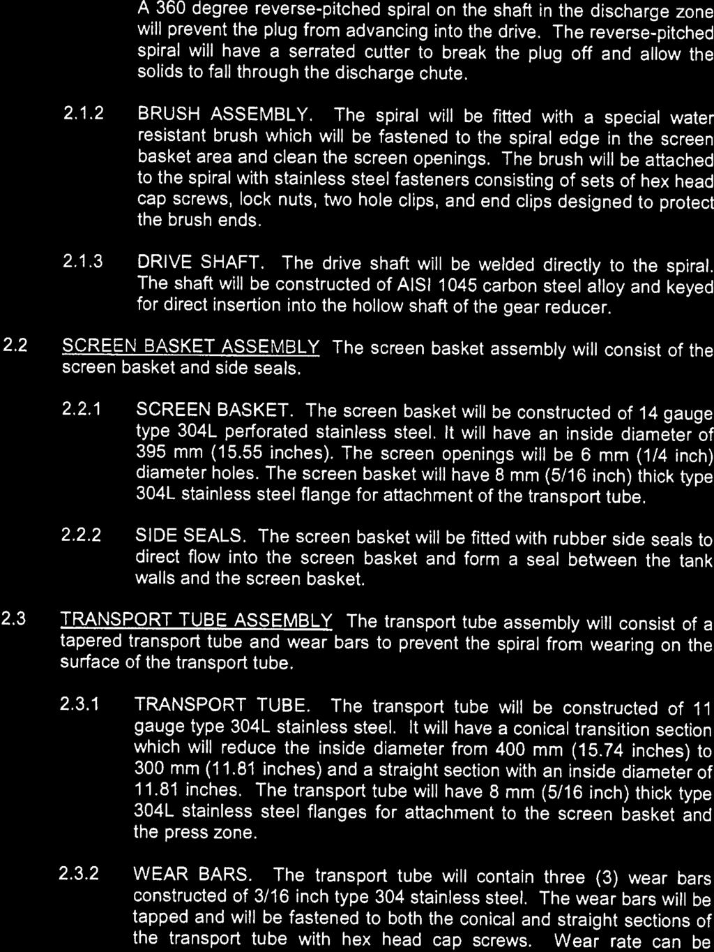


100

101
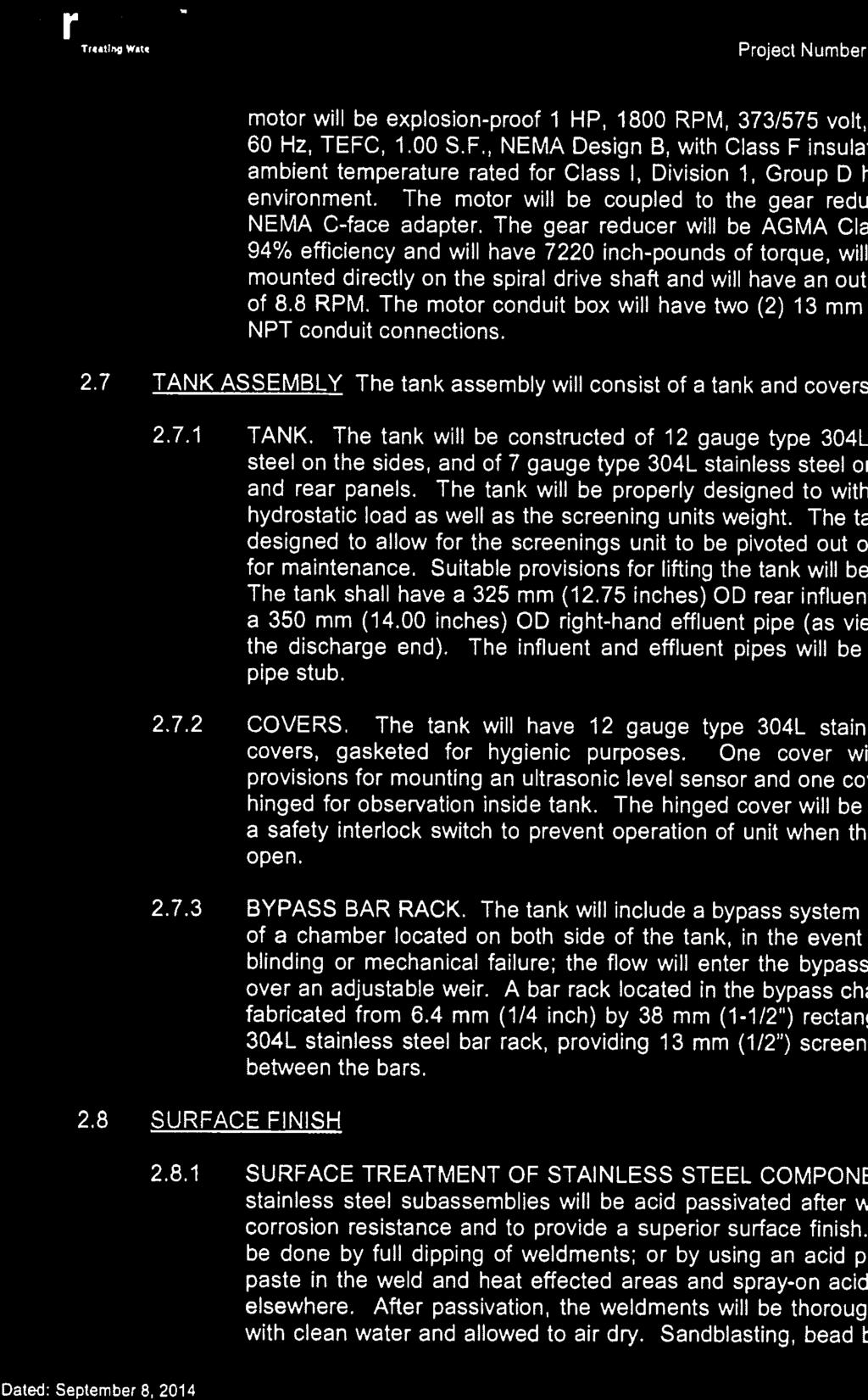
102


103

104
105
106


107


108


109
110
111 PROCESS CONTROL NARRATIVE Appendix C Salsnes Filter Control Philosophy C-1
112
113 Controls Philosophy PART F CONTROLS PHILOSOPHY CPXXXXXX - REV 0.0 Salsnes Filter Original Instructions Submittal
114 Controls Philosophy Salsnes Filter Original Instructions Submittal
115 Project # xxxxxx CONTROLS PHILOSOPHY Salsnes Filter Template CONTROLS PHILOSOPHY Salsnes Filter Templatee Salsnes Filter System... 3 Glossary System Overview Control Strategy Priorities Safety Features Alarm Classifications CPP IO Layout... 4 Discrete Inputs Embedded I/O Discrete Outputs Embedded I/ /O Discrete Inputs I/ O Module Discrete Inputs I/ O Module Analog Inputs I/O Module Communications Layout CPP Standard Operation Operation Modes Alarms Operator Interface Filter Belt Control Architecturee Operation Modes Alarms Operator Interface Blower Control Architecturee Operation Modes Alarms Operator Interface - Overview Sludge Screw Control Architecturee Rev 0.0 Page 1 of 24 Salsnes Filter 25 July 14
116 Project # xxxxxx 6.2 Operation Modes Alarms Operator Interface Level Transmitter Control Architecturee Alarms Operator Interface Blower Pressure Transmitter Control Architecturee Alarms Operator Interface Hot Water Valve Control Architecturee Operation Modes Alarms Operator Interface Operatorr Interface Alarms Passwords Data logging/trending Screen Interfacee with Plant Control System Hardwired Status Signals Revision History Rev 0.0 Page 2 of 24 Salsnes Filter 25 July 14
117 Project # xxxxxx 1.0 Salsness Filter System The objective of this document is to provide details regarding the control strategy for the Salsnes Filter (SF) System. The control philosophy outlines the major hardware components, system status, alarm conditions, and modes of operation of the System. 1.1 SF PLC IO CPP OIT VFD Glossary Salsnes Filter Programmable Logic Controller Inputs/Outputs Control Power Panel. The CPP contains the local power distribution components for each system. It also houses the PLC, IO, and the Operator Interface Terminal Operator Interface Terminall Variable Frequency Drive 1.2 System Overview The SF System uses a PLC based control system that provides optimized control of a mesh Filter Belt. Each SF System is powered by a CPPP that houses the PLC, IO, and OIT which provides local control and monitoring. The PLC will control the Filter Belt rotational speed to obtain optimum separation of the incoming material. The speed will be varied by a Filter Motor to maintain a specified water level in the inlet well. The solids are depositedd off of the belt into an outlet well, where optional dewatering may be performed by the Sludge Screw. 1.3 Control Strategy Priorities The strategic operational priorities of the SF System controls are as follows (arranged in order of priority): Operator and equipment safety Maximize Separation, Thickening, and Dewatering Efficiency 1.4 Safety Features The SF System control strategy employs an equipment protection interlock and monitors a number of alarm conditions that will result in controll actions designed to maximize efficiency. There is one critical interlock signal that is hardwired to the CPPP that will disable the motors in the SF System. This critical interlock is: Emergency Stop Push Button Dewatering Screw Failure Options: Air Pressure Not Present, Ventilation Differential Pressure Alarm, External Sludge Bin Fault Rev 0.0 Page 3 of 24 Salsnes Filter 25 July 14
118 Project # xxxxxx Certain other alarm conditions will trigger a control action that will result in the filter motor running at a fixed high speed. Examples of these types of alarm conditions are more fully described later in this document. 1.5 Alarm Classificat tions Critical A critical alarm will cause an immediate system shutdown. Any inlet water will flow from the inlet to the security overflow andd no filtration is expected Major A major alarm will not stop the filtration process, but the machine will change to a fixed speed (that is adjustable manually) ) on the Filterr Belt to ensure that the system will cope with the flow. Reduced filtrationn performancee is expected Minor A minor alarm will have no impact on the system. This alarm is intended to provide warning and maintenance information. 2.0 CPP IO Layout Type Details CPU Allen Bradley Compact Logix Controller Embedded Discrete Input 16 Input, 24VDC Embedded Discrete Output 16 Output, 24VDC Discretee Input 8 Input, 24VDC Discretee Input 8 Input, 24VDC Analog Input I 4 Input 0-20mA Model 1769-L16ER-BB1B Embedded Processor I/O Embedded Processor I/O 1734-IB IB IE4C Rev 0.0 Page 4 of 24 Salsnes Filter 25 July 14
119 Project # xxxxxx In0 In1 In2 In3 In4 In5 In6 In7 In8 In9 In10 In11 In12 In13 In14 In15 Channel 2.1 Discretee Inputs Embedded I/O Description Tagname Range Emergency Stop Pressed Panel Temperature OK 07 HS303 1=Estop Pressed 0=High Temperature Surge Protection Tripped 07 YA307 1=Protection Error Phase Monitoring Relay: Phase Errorr Phase Monitoring Relay: Voltage Error Spare Air Conditioner Faulted 07 JA304B 07 EA304A 1=Phase Error 1=Voltage Error 1=Air Conditioner Error Air Blower Cooling Fan Running 07 M330A 1=Motor Running 24VDC Power Supply OK 0=Power Supply Error UPS Main Supply Faulted UPS Battery Faulted Air Blower Running 07 YA308A 07 YA308B 07 M330 1=UPS Active 1=Battery Error 1=Motor Running Air Blower Overload Tripped 07 M330 1=Overload Tripped Inlet Valve Opened Inlet Valve Closed Air Conditioner Overload Tripped 07 ZSO ZSO310 1=Valve Open 1=Valve Closed 1=Overload Tripped Rev 0.0 Page 5 of 24 Salsnes Filter 25 July 14
120 Project # xxxxxx Out0 Out1 Out2 Out3 Out4 Out5 Out6 Out7 Out8 Out9 Out10 Out11 Out12 Out13 Out14 Out15 Channel 2.2 Discretee Outputs Embedded I/O Description Spare Air Blower Start Cooling Fan Start Air Blower Open Hot Water Valve Spare Open Drain Valve Open Inlet Valve Close Inlet Valve Spare Start external sludge screw forward Start external sludge screw reverse Spare Spare Status Bit 1 Configurable Status Bit 2 Configurable Status Bit 3 Configurable Tagname 07 M330A 07 M SV SV FV FV M M YA390A 07 YA390B 07 YA390C Range 1=Start Motor 1=Start Motor 1=Open Valve 1=Open Valve 1=Open Valve 1=Close Valve 1=Screw Fwd 1=Screw Rev 1=Configured Condition True 1=Configured Condition True 1=Configured Condition True Rev 0.0 Page 6 of 24 Salsnes Filter 25 July 14
121 Project # xxxxxx 2.3 Discretee Inputs I/O Module 1 Channel Description Tagname Range In0 Spare In1 HMI Mode (switch in cabinet door) 07 HS301A 1=HMI mode In2 Local On Mode (switch in cabinet door) 07 HS301B 1=Local mode In3 Remote Permissive Run (customer) 07 YA391 1=OK to run In4 Remote Reset (customer) 07 YA392 1=Reset In5 External Sludge Conveyor Running 07 M352 1=Motor On In6 Inlet Valve Overload Tripped 1=Overload Tripped In7 Spare 2.4 Discretee Inputs I/O Module 2 Channel Description Tagname Range In0 Spare In1 Spare In2 Hot Water Pressure Low 07 PSL362B 1=Low Pressure In3 Hot Water Temperaturee Low 07 TSL362A 1=Low Temperaturee In4 Spare In5 Spare In6 Spare In7 Spare 2.5 Analog Inputs I/O Module 3 Channel Description Tagname Range In0 Filter level 07 LT3000 TBD In1 Air pressure 07 PT psi In2 Flow meter 07 FI3111 TBD In3 Spare Rev 0.0 Page 7 of 24 Salsnes Filter 25 July 14
122 Project # xxxxxx 2.6 Communications Layout Devicee Description Address Subnet Mask Gateway Tagname CPP PLC CPP OIT CPP WiFi Gateway/Local Gateway CPP Modem CPP Filter VFD CPP Sludge Screw VFD CPP Blower VFD (optional) M M M CPP 3.1 Standard Operation Startup The startup sequence is as follows (system in HMI mode, all devices in Automatic): If PLC is configured to control the inlet valve, this valve will be opened when the filter is Local On or in HMI mode and a filter Start is requested either throughh a HMI start request or byy a remote SCADA or hardwired Permissive Run request System remains idle until the water level in the inlet welll reaches the start level set-point Once the water level in the inlet well reaches the start level set-point, the following motors willl start: o Blower Motor (starts at adjustable water level before filter) o Blower Motor Cooling Fan o Filter Motor o Sludge Screw Motor (after adjustable time delay) The Blower Motor must be at full speed in Auto before the Filter Motor will be allowed to start the blower start level may be adjusted in order to optimize the system The filter belt speed may be set using the following configurable modes: o PID controlled to maintain a target water level set-point o Directly proportional to the water levell o Fixed speed manual mode The Filter Motor will stop if the water level drops below the stop level set- point Rev 0.0 Page 8 of 24 Salsnes Filter 25 July 14
123 Project # xxxxxx The controlled shutdown sequence is as follows: System remains running while thee water level in the inlet well stays above the stop level set-point The critical shutdown sequence is as follows: Controlled Shutdown Once the water level drops below the stop level set-point, the Filter Motor will stop immediately The Sludge Screw Motor will stop after a configurable time delay, after the Filter Motor has stopped The Blower Motor will then stop after the stop delay time expires The Blower Motor Cooling Fan will stop after a hard coded 1-minute time delay, after the Blower Motor hass stopped Optionally the filter stop sequence may also be triggered by the loss of the plant permissive digital input signal which will also result in the inlet valve being closed (if applicable) Critical Shutdown System shutdown signal is issuedd due to a critical alarm The Blower Motor turns off The Blower Motor Cooling Fan turns off The Filter Motor turns off The Sludge Screw Motor turns off Inlet valve close (if applicable) All valves and motors will shut down simultaneously System will not re-start until the critical alarm has been cleared Hot Water Flush Automatic Hot Water Flushing of the filter mesh and dewatering basin is performed as follows: System must be in HMI mode with selected to Automatic Mode, and no critical or major alarms are present The Hot Water Flush interval time, which is set from the OIT, expires The Hot Water Flush Valve opens The Filter Motor runs at a constant speed The Hot Water Flush Valve closes after the flush duration time expires The Filter Motor speed regulationn mode goes back to normal control Rev 0.0 Page 9 of 24 Salsnes Filter 25 July 14
124 Project # xxxxxx 3.2 Operation Modes Off When the Filter Control Switch is in thee Off position, the CPP control of the motors or valves. PLC will have no On When the Filter Control Switch is in thee On position, the CPP PLC will have no control of the motors or valves. In this mode the filter starters and drives will all be electrically activated and will operate at a fixed speed using the manual speed setcontrol points on the HMI HMI Mode When the filter control mode switch is in the HMI position the CPP PLC has of all motors in the system based on the configurationn set in the CPP OIT. From the OIT, the filter system HMI mode can be set to Off, Manual, or Auto modes. When the filter system is set to HMI-Manual mode, each motor and valve may be individually requested to be started/opened or stopped/closed. When the filter control mode switch transitions to the HMI position,, the PLC will automatically set the HMI mode to Automatic and all valves and motors will be automatically controlled by the PLC. The HMI mode must be switched to OFF or Manual if direct operator control of the devices is required. Normal Operation of the SF System is to have all Motors and valves automatically controlled with the system in HMI Autoo mode. Fully automatic operation of the system is described in section 3.1 Standard Operation. HMI Manual Operation of individual Motors is described later in thiss document. 3.3 Alarms Each CPP alarm conditionn will generate a corresponding system level alarm. Classification Alarm Description Alarm Condition Delay Minor Major The Phase Monitoring relay detected a Main Power Supply Failure loss of main input power on one or more phases. The UPS has detected a loss of main UPS Supply Activated power and the PLC is now operating on UPS power. Critical UPS Battery Fault The UPS has detected that the battery None pack is faulted. Enabled The Emergency Stop located at the Filter Emergency Stop Activated is activated. Key Switch Reset is required to enable the system. None The Filter Motor, Blower Motor, or Sludge Motor Failure Screw Motor has failed to respond to a control command (start/stop) within a Critical certain amount of time Critical Enabled Enabled Enabled Enabled Rev 0.0 Page 10 of 24 Salsnes Filter 25 July 14
125 Project # xxxxxx Alarm Description Alarm Condition Delay Minor Classification Major Critical Service is due (Blower, Sludge Screw, Filter) Indicates that service is required based on run time of equipment (should be 300 hours initially on blower, then 3000 hours) None Enabled 3.4 Operator Interface Display Data The OIT will have a System Overview screen that will be used to display system status information and to provide operator control functions. The System Overview screen will containn the following information: System status System fault indicators 4.0 Filter Belt 4.1 Control Architecture The Filter Belt, which contains a filter mesh mounted on a removable cartridge, is used to draw waste material from the inlet to outlet sludge conveyor. Water is separated from the material as it is transported on the mesh towards the outlet well. A Filter Motor, which rotates the Filter Belt, is driven by a VFD that regulates the speed based on a PID control algorithm. The speed is continuallyy regulated in order to maintain an enterable inlet water level set-point. Optionally the system may be configured to operate the filter speed in a proportional mode so that the speed of the filter is proportionally increased as the filter water level increases, but a target water level is nott maintained. The VFD is controlled by a network communication signal controlled from the CPP PLC. 4.2 Operation Modes System Mode - Off When the System Mode selector switch start. is set to OFF, the Filter Belt Motor will not System Mode On When the System Mode selector switchh is set to ON, the Filter Belt Motor will be started by an electrical interlock that will force the motor to run at a fixed speed configured by the manual HMI set-points.. Rev 0.0 Page 11 of 24 Salsnes Filter 25 July 14
126 Project # xxxxxx System Mode HMI - Off When the System Mode selector switch is in the HMI position, and the HMI mode is set to Off, the CPP PLC will keep motor turned off and will not automatically start the Filter Motor, regardless of Filter level System Mode HMI - Manuall When the System Mode selector switch is in the HMI position, and the HMI mode is set to Manual, the CPP PLC will start and run Filter Motor according to requests by the operator from the HMI. The speed of the Filter Motor will be controlled by an operator entry on the OIT. NOTE: This mode should not be used when the filter inlet valve is open unless the blower and sludge screw is also operating System Mode HMI - Auto When the System Mode selector switch is in the HMI position, and the HMI mode is set to Auto, the CPP PLC has control off the Filter Belt. See section 3.1 Standard Operation. 4.3 Alarms Each Filter Belt alarm condition will generate a corresponding system level alarm. Classification Alarm Description Alarm Condition Delay Minor Major Critical The VFD for the Filter Motor has 07-M320 Fault Filter Cloth Enabled reported a fault condition 4.4 Operator Interface Display Data - Overview The OIT will have a System Overview screen that will be used to display Filter Belt status information and to provide operator control functions. The screen will contain the following information: Filter Motor status Filter Motor fault indicators Filter Motor manual control Display Data - Information Filter Motor running time (today, yesterday, total) Filter Motor starts (today, yesterday, total) Rev 0.0 Page 12 of 24 Salsnes Filter 25 July 14
127 Project # xxxxxx Operator Settings Users will have access to screens which will allow them to view and modify the following Filter Belt options and settings: Adjust the Mode of the Filter Belt t Motor Adjust the Start and Stop Level of the Filter Belt Motor Level set-point for Filter High level alarm set-point Minimum and maximum speed Filter Acceleration and Deceleration time Adjust the speed set-point of the Filter Belt Motor when it is in Manual 5.0 Blower 5.1 Control Architecture The Blower is used to provide air for the Air Knife Mesh Cleaning System, which is used to blow material off of the filter mesh into the sludge conveyor. The Blower Motor is driven by a soft starter and maintains a fixed speed based on the selected blower specification. The soft starter is controlled by a signal communicated from the CPP PLC. A Blower Cooling Fan is mounted in the Blower enclosure. It will run when the Blower Motor is on, and it will stop when the Blower Motor stops after a hard coded 1 minute time delay. 5.1 Operation Modes System Mode - Off When the System Mode selector switch is set to OFF, the Blower Motor and Cooling Motor will not start System Mode On When the System Mode selector switch is set to ON,, the Blower Motor and Cooling Motors will be started by an electrical interlock System Mode HMI - Off When the System Mode selector switch is in the HMI position, and the HMI mode is set to Off, the CPP PLC will keep motor turned off and will not automatically start the Blower Motor and Blower Cooling Motor, regardless of Filter level System Mode HMI - Manuall When the System Mode selector switch is in the HMI position, and the HMI mode is set to Manual, the CPP PLC will start and run Blower Motor and Blower Cooling Motor according to requests by the operator from the HMI. Rev 0.0 Page 13 of 24 Salsnes Filter 25 July 14
128 Project # xxxxxx System Mode HMI - Auto When the Filter Control Switch is in the HMI position, and the HMI mode is set to Auto, the CPP PLC has control of the Blower. See section 3.1 Standard Operation. 5.2 Alarms Each Blower Motor alarm condition will generate a corresponding system level alarm. Classification Alarm Description Alarm Condition Delay Minor Major Critical The VFD for the Blower Motor 07-M330 Fault Blower Enabled has reported a fault condition 07-M330A Fault Blower Cooling The Blower Motor Cooling Fan Enabled Fan has reported a fault condition 5.3 Operator Interface - Overview Display Data The OIT will have a System Overview screen that will be used status information and to provide operator control functions. The screen will contain the following information: Blower Motor status Blower Motor fault indicators Blower Motor manual control to display Blower Display Data - Information Blower Motor running time (today, yesterday, total) Blower Motor starts (today, yesterday, total) Operator Settings Users will have access to screens which will allow them to view and modify the following Blower Motor options and settings: Adjust the Mode of the Blower Motor Start and Stop blower motor in manual mode Adjust the Stop Delay time of thee Blower Motor Adjust the Stop Delay speed of the Blower Motor Adjust the speed set-point of the Blower Motor Rev 0.0 Page 14 of 24 Salsnes Filter 25 July 14
129 Project # xxxxxx 6.0 Sludge Screw 6.1 Control Architecture The Sludge Screw is used to dewater and/or convey the Sludge that has been transported by the filter mesh. The Sludge is collected and conveyed by the screw where it is optionally pressed and dewatered before exiting the SF System. The Sludge Screw Motor is driven by a VFD that maintains a fixed speed target based on a configurable setting from the CPP OIT. The Sludge Screw may be operated in forward or reverse direction in manual mode. The VFD is controlled by a signal communicated from the CPP PLC. 6.2 Operation Modes System Mode - Off When the System Mode selector switch iss set to OFF, the Sludge Screw will not start System Mode On When the System Mode selector switch iss set to ON, the Sludge Screw will be started by an electrical interlock System Mode HMI - Off When the System Mode is in the HMI position, and the HMI mode is set to Off, the CPP PLC will keep the motor turned offf and will nott automatically start the Sludge Screw, regardless of Filter level System Mode HMI - Manuall When the System Mode selector switch is in the HMI position, and the HMI mode is set to Manual, the CPP PLC will start and run the Sludge Screw according to requests by the operator from the HMI. The speed of the Sludge Screw will be controlled by an operator entry on the OIT System Mode HMI - Auto When the System Mode selector switch is in the HMI position, and the HMI mode is set to Auto, the CPP PLC has controll of the Sludge Screw. See section 3.1 Standard Operation. 6.3 Alarms Each Sludge Screw Motor alarm condition will generate a corresponding system level alarm. Classification Alarm Description Alarm Condition Delay Minor Major Critical The VFD for the Sludge Screw 07-M350 Fault Sludge Screw Motor has reported a fault Enabled condition Rev 0.0 Page 15 of 24 Salsnes Filter 25 July 14
130 Project # xxxxxx 6.4 Operator Interface Display Data - Overview The OIT will have a System Overview screen that will be used Screw status information and to provide operator control functions. The screen will contain the following information: Sludge Screw Motor status Sludge Screw Motor fault indicators Sludge Screw Motor manual control to display Sludge Display Data - Information Sludge Screw Motor running timee (today, yesterday, total) Sludge Screw Motor starts (today, yesterday, total) Operator Settings Users will have access to screens which will allow them to view and modify the following Sludge Screw Motor options andd settings: Adjust the Mode of the Sludge Screw Motor Adjust the Stop Delay time of thee Sludge Screw Motor Adjust the speed set-point of the Sludge Screw Motor 7.0 Level Transmitt ter Alarm Description 07-LT300 HL Level Filter 07-LT300 Overflow Filter 07-LT300 Defect 7.1 An inlet well water level transmitter is required in order to determine when to start and stop the SF System. The water level is also used to control the speed of the Filter Belt. The value is supplied to the CPP PLC via a 4-20 ma analog signal that is passed through a smoothing algorithm to reduce noise. This signal is then scaled to engineering units based on a full scale level set-point. 7.2 Control Architecture Alarms Each level transmitter alarm condition will generate a corresponding system level alarm. Alarm Condition The level is greater than the High Level Alarm value The level is greater than the Overflow limit. The level transmitter is not within the allowable 4-20mA range Delay Minor Enabled Enabled Classification Major Enabled Critical Rev 0.0 Page 16 of 24 Salsnes Filter 25 July 14
131 Project # xxxxxx 7.3 Operator Interface Display Data - Overview The OIT will have a System Overview screen that will be used to display Transmitter status information and to provide operatorr control functions. The screen will contain the following information: Level Transmitter status Level Transmitter fault indicators Level Display Data - Information Overflow time (today and yesterday) Overflow time total # of overflows (today and yesterday) Total number of overflows Operator Settings Users will have access to screens which will allow following Level Transmitter options and settings: Adjust the Inlet Well water level set-point Adjust the start and stop water level limit Adjust the High Level alarm limit Adjust the Overflow alarm limit them to view and modify the 8.0 Blower Pressure Transmitter 8.1 Control Architecture A pressure transmitter is required in order to determine if the Blower is operating correctly. The value is supplied to the CPP PLC via a 4-20 ma analog signal that is passed through a smoothing algorithm to reduce noise. This signal is then scaled to engineering units based on a full scale pressure set-point. 8.2 Alarms Each pressure transmitterr alarm condition will generate a corresponding system level alarm. Classification Alarm Description Alarm Condition Delay Minor Major Critical The pressure is less than the 07-PT331 LL Pressure Blower Enabled Low Level Alarm value The pressure is greater than the 07-PT331 HL Pressure Blower Enabled High Level Alarm value Rev 0.0 Page 17 of 24 Salsnes Filter 25 July 14
132 Project # xxxxxx Alarm Description Alarm Condition Delay Classification Minor Major Critical 07-PT331 Defect The pressure transmitter is not within the allowable 4-20mA range Enabled 8.3 Operator Interface Display Data The OIT will have a System Overview screen that will be used to display Pressure Transmitter status information and to provide operatorr control functions. The screen will contain the following information: Pressure Transmitter status Pressure Transmitter fault indicators 9.0 Hot Water Valve 9.1 Control Architecture Hot Water is used for filter belt cleaning. All motors must be operating and in Automatic mode before a Hot Water flush will occur. The hot water valve is controlled by the CPP PLC via a discrete open signal, or the OIT in manual mode. The CPP PLC will automatically perform a Hot Water flush based on a configurable time delay. The Blower Motor, Blower Motor Cooling Fan, Filter Motor, and Sludge Screw Motor will start when the Hot Water Valve is being commanded to open via the in Auto mode. 9.2 Operation Modes System Mode - Off When the System Mode selector switch open. is set to OFF, the Hot Water valve will not System Mode On When the System Mode selector switch is set to ON, the Hot Water valve will remain closed System Mode HMI - Off When the System Mode is in the HMI position, and the HMI mode is set to Off, the CPP PLC will keep the Hot Water valvee closed and will not automatically open the Hot Water valve. Rev 0.0 Page 18 of 24 Salsnes Filter 25 July 14
133 Project # xxxxxx System Mode HMI - Manuall When the System Mode selector switch is in the HMI position, and the HMI mode is set to Manual, the CPP PLC will open and close the Hot Water valve according to requests by the operator from the HMI System Mode HMI - Auto When the System Mode selector switch is in the HMI position, and the HMI mode is set to Auto, the CPP PLC has control of the Hot Water valve. See section 3.1 Standard Operation. The Hot Water flush timer will count down to control the operation of the valve only in HMI-Autoo mode. In all other modes, the Hot Water flush timer will be reset and suspended. 9.3 Alarms Each transmitter alarm condition will generate a corresponding system level alarm if optional sensors are configured in the filter system. Classification Alarm Description Alarm Condition Delay Minor Major Critical The water temperature is less 07-TSL362A Hot water than the Low Temperature temperature low Alarm value Enabled* 07-PSL362B Hot water pressure The Hot water pressure is low low Enabled* * Enabled only during a hot water flush 9.4 Operator Interface Display Data The OIT will have System Overview and Flushing screens that will be used to display Hot Water Valve status information and too provide operator control functions. The screens will contain the following information: Valve status Adjust the Remote Mode of the Hot Water Valve Manual flush one control Operator Settings Users will have access to screens which will allow them to view and modify the following Hot Water Valve options and settings: Adjust the automatic Hot Water Flush interval delay time Adjust the automatic Hot Water Flush duration time Adjust the Hot Water temperaturee alarm delay Rev 0.0 Page 19 of 24 Salsnes Filter 25 July 14
134 Project # xxxxxx Operator Interface 10.1 Alarms Alarms generated by the CPP PLC will be logged and displayedd on the local OIT Alarm screen, as well as being passed to the Plant Control System. Each alarm generated will be time and date stamped at the OIT. The most recent alarms are recorded and displayed in the alarm history register of the OIT. The OIT for the equipment described within this document will each contain 3 levels of password protection; Operator, Technician and OEM level. Operator level has less user privileges for accessing and changing parameters for the system. Technician level has a higher level of user privileges and OEM level has full system configuration privileges. Users will be prompted to log in if trying to view or operate items with insufficient user privileges. Unique user passwords will not be provided for this system. A system log will record a history of the user log in access. The OIT will store data points into a datalog file for retrieval for offline analysis, or for display on a Trend screen. The sample rate of the data pointss will be fixed at 5 secondss between samples and data willl be stored for 3 days in a FIFO buffer. The following data will be stored: 10.2 Passwords 10.3 Data logging/trending Screen Filter Level Filter Belt Speed Blower Air Pressure Filter Flow Filter Motor Voltage Filter Motor Current Sludge Screw Motor Voltage Sludge Screw Motor Current Rev 0.0 Page 20 of 24 Salsnes Filter 25 July 14
135 Project # xxxxxx 11.0 Interface with Plant Control System The filter PLC will provide 3 discrete outputs (Status Bit 1 to 3) which can be configured as desired to provide alarm or operating status information. Multiple outputs may also be assigned to the same alarm output such that if anyy of the assigned conditions are present, the output contact will be closed. The following signals are available for assignment to these outputs: 11.1 Hardwired Status Signals Filter motor running Sludge screw running Air blower running Water sampler pulse Hot water flush active Drain valve open Filter in Automatic mode Common Critical Alarm Common Major Alarm Common Minor Alarm Rev 0.0 Page 21 of 24 Salsnes Filter 25 July 14
136 Project # xxxxxx 12.0 Revision History Rev. Description Rev By Date 0.0 Initial release for Review EC 25 June, 2014 Rev 0.0 Page 22 of 24 Salsnes Filter 25 July 14
137 PROCESS CONTROL NARRATIVE Appendix D Grit Removal Control Philosophy D-1
138
139 5.2 CONTROL FUNCTIONAL DESCRIPTION Tsawwassen FN SSTP DB
140 TSAWWASSEN FIRST NATION SSTP Functional Description PROJECT: FUNCTIONAL DESCRIPTION Page 1 of 24
141 TSAWWASSEN FIRST NATION SSTP Functional Description PROJECT: TABLE OF CONTENTS 1 GENERAL DESCRIPTION CONTROL LAYOUT HARDWARE CONNECTION LOCAL CONTROL Pilot lights Pushbuttons Local Operator Interface TRANSMISSION OF SIGNALS ANALYSER AND DETECTOR Analyser Display on operator interface Scaling Out of range Process alarm Calibration mode Detectors General Digital alarm delay Security logic Activation conditions for alarms VALVES Operational Mode TYPICAL MOTOR Operational Mode Local disconnect switch Wired logic stop Motor alarm delay Start fault alarm Overload alarm Running time SECURITY LEVEL ALARM MANAGEMENT Alarm Priorities PLC low battery alarm Power failure alarm GENERAL EMERGENCY STOP General emergency stop actions Recovery after general emergency stop General emergency stop alarm ROTARC TYPE SB SHAFTLESS SPIRAL FINE SCREEN INTERFACE CONTROLS Displays Operators Local station AUTOMATION Automatic Mode High Water Differential Level Sequence (Ultrasonic) High Water Level Sequence (Float) Clock Sequence Screen Cleaning Cycle Compaction/Dewatering Zone Cleaning Sequence Manual Mode Manual Test Page 2 of 24
142 Page 3 of 24 TSAWWASSEN FIRST NATION SSTP Functional Description PROJECT: Local jog Emergency stop MOTOR Shaftless Spiral Fine Screen motor Thermal protection Jamming protection VALVES Screening Zone Solenoid Valve Compaction/Dewatering Zone Solenoid Valve ROTOPAC TYPE RLK SHAFTLESS SCREW CONVEYOR INTERFACE CONTROLS Displays Operators Local station AUTOMATION Automatic Mode Manual Mode Manual Test Local jog Emergency stop/pull cord MOTOR Shaftless spiral conveyor motor Thermal protection Jamming protection Zero speed protection MECTAN GRIT REMOVAL MECHANISM (WITH GRIT PUMPS) INTERFACE CONTROLS Displays Operators AUTOMATION Automatic Mode Normal operation Extraction sequence Manual Mode Emergency stop VALVES Water scour solenoid valve MOTORS Agitator motor Agitator motor fault Agitator motor overload Grit pump 1 motor Grit pump motor fault Grit pump motor overload Grit pump 2 motor Grit pump motor fault Grit pump motor overload SAM TYPE GDS GRIT DEWATERING SCREW INTERFACE CONTROLS Displays Operators Local station AUTOMATION Automatic Mode... 23
143 TSAWWASSEN FIRST NATION SSTP Functional Description PROJECT: Normal operation Manual Mode Emergency stop MOTORS Grit dewatering screw motor Motor fault Motor overload Motor overcurrent Page 4 of 24
144 TSAWWASSEN FIRST NATION SSTP Functional Description PROJECT: General description The following document describes the typical operation of the system. Some of the described components may not be supplied by John Meunier Inc. The control system shall be supplied by the pre-treatment equipment manufacturer. It shall provide total automatic machine operation with protection against overload conditions, which might damage the equipment. The control system shall be rated for the following classifications: Main control cabinet NEMA-4X SS304, Non-hazardous area Local control stations NEMA-7, Class I, Division I, Group D The following basic components shall be assembled in the system main control panel enclosure and pre-wired to identified terminal blocks. This enclosure shall provide upfront panel door operation. Panel hook up shall be made on site by the contractor. a. Main fusible type disconnect breaker sized for the application shall be front panel mounted c/w NEMA-4X operating handle and interlock; b. Full voltage reversible / non-reversible motor starters (IEC rated) sized for the application with manual starter, circuit and adequate magnetic overload and over current protection; c. Dry contacts shall be available for external status and alarm feedback; d. Safety barrier for digital signals (float switch); e. Operator devices shall be 22 mm diameter, type NEMA-4X. The system is composed of the following equipments (with controls): Two (2) ROTARC Type SB Shaftless Spiral Fine Screens One (1) ROTOPAC Type RLK Shaftless Screw Conveyor One (1) MECTAN Grit Removal Mechanism Two (2) Grit Pumps One (1) SAM Type GDS Grit Dewatering Screw 1.1 Control layout An Allen Bradley MicroLogix 1400 PLC controls the system. This PLC is located within a NEMA 4X stainless steel control panel. The control panel is equipped with an Exter T60 touch-screen operator interface from BEIJER. 1.2 Hardware connection All motors and instruments are controlled by the system s panel. Panel connections on site will be done by others and are not included in John Meunier s scope of supply. Page 5 of 24
145 TSAWWASSEN FIRST NATION SSTP Functional Description PROJECT: Local control Pilot lights The pilot lights are installed on the control panel door. They are used to identify the operating condition that prevails: Pilot light Color State Operating condition Steady The panel is powered. "POWER ON" White Off The panel is not powered. Blinking An alarm signal has been activated but not acknowledged. "GENERAL ALARM" Red Steady All activated alarm signals were acknowledged. Off No alarm is present Pushbuttons Push buttons and selectors are installed on the control panel door. They are used for general emergency stop and to reset faults: Pushbutton Color Type "EMERGENCY STOP" Red "Mushroom" "ALARM RESET" Black "Momentary" Local Operator Interface The operator interface provided with this system will allow to access all manual and automatic functions of the control system. The setting of all adjustable delays inserted in the auto sequence is accessible at the operator s interface, but the access is limited. All data entries are limited in minimum and maximum to avoid faulty entries. Local operator interface allows: 1. Access to different screens by a main menu. 2. Automatic/Manual mode selection for all valves and motors. 3. Open/Close or Start/Stop selection for manual operation of valves and motors. 4. Visualization of motor and valve status 5. Visualization and acknowledgement/reset of alarms 6. Visualization of analog measurements with engineering values or graphics. 7. Modification of ranges, set points and delays. Pages are accessible with a valid password. 1.4 Transmission of signals Some signals are transmitted by wired-logic to the system s panel or from the system s panel. These signals might be used during start-up and/or troubleshooting; they might also be used to start/stop other related equipments. See appended I/O list. Page 6 of 24
146 TSAWWASSEN FIRST NATION SSTP Functional Description PROJECT: Analyser and detector Analyser Display on operator interface Each analog input is displayed in engineering units Scaling Each analog input is scaled in engineering units. The scale values must be set up on the operator interface to match the range of the instrument Out of range The minimum range and maximum range of an instrument are defined as the engineering values respectively associated to 4 ma and 20 ma signals. They stand for the limits of the operational scale of the instrument. All instruments mentioned in this document have a programmed Out of Range alarm. If signals exceed 20.5 ma or drop below 3.5 ma for over 60 seconds, an Out of Range alarm is activated and the instrument s reading is forced to 0. All process alarms for the instrument are also deactivated Process alarm A process alarm is activated when the instrument s reading is over or under the set point (determined by operator) and when the common analog alarm delay ran out. The most common are HH (very high), H (high), L (low) and LL (very low). Process alarms are deactivated when corresponding transmitter is out of range. When an alarm has a different delay than the common analog alarm, it is specified with the description of the instrument s alarm Calibration mode The calibration mode sets the engineering value of the instrument at its last value, so the calibration of the instrument may be done without activating useless alarms. When the instrument is in calibration mode the operator is able to modify the engineering value at the interface Detectors General Detectors give a digital signal. A change of state produces an alarm and/or an action. A common alarm delay, adjustable or not, is always programmed to avoid false alarms. Detectors may be high level switches, low level switches, etc Digital alarm delay The digital alarm delay is common to all detectors. If a detector s delay is different from common delay, it is specified in the instrument s section Security logic When a detector s dry contact is used to trigger an alarm, it is wired to trigger the alarm when the circuit opens (power loss) Activation conditions for alarms The activation conditions for process and deviation alarms are particular to each instrument and depend on the process phase in which it is required. When an alarm requires activation condition, these are noted with the instrument s description. Page 7 of 24
147 TSAWWASSEN FIRST NATION SSTP Functional Description PROJECT: Valves Operational Mode Interface manual mode: A valve may operate in MANUAL mode if the following conditions are met: 1. If manual mode is selected on interface 2. If the local control station selector or the override module is in REMOTE position 3. If there is no detected fault (ALARM) 4. If the emergency stop is not activated Actions: Open: the valve opens if there is no prevailing closing condition through wired logic. Close: valve closes. Auto mode: A valve may operate in AUTO mode if the following conditions are met: 1. If automatic mode is selected on interface 2. If the local control station selector or the override module is in REMOTE position 3. If there is no detected fault (ALARM) 4. If the emergency stop is not activated 5. If the automatic open/close conditions are met 1.7 Typical Motor Operational Mode Interface manual mode: A motor may operate in manual mode if the following conditions are met: 1. If manual mode is selected on interface 2. If local selector or override module is in Auto position 3. If no fault is detected (ALARM) 4. If the emergency stop is not activated Actions: Start: the motor starts if there is no prevailing fault condition through wired logic. Stop: motor stops. Auto mode: A motor may operate in auto mode if the following conditions are met: 1. If auto mode is selected on interface 2. If local selector or override module is in Auto position 3. If no fault is detected (ALARM) 4. If the emergency stop is not activated 5. If auto start conditions are met Local disconnect switch If a disconnect switch is supplied and installed (by others), it is lockable and it is installed near the motor. It contains an auxiliary contact that opens the starter s control circuit. Note: the disconnect switch must never be activated when motor is running. The motor should be stopped before activating or deactivating the disconnect switch. Page 8 of 24
148 TSAWWASSEN FIRST NATION SSTP Functional Description PROJECT: Wired logic stop Regardless of selector s position and selected mode, hardwired logic stop conditions protect motor and force its stopping. These conditions, if relevant, are described in each the motor sections Motor alarm delay For each motor alarm, a delay is always programmed. This delay is common to all motors unless otherwise indicated in motor description Start fault alarm If the motor start command is activated, the running status is not and the alarm delay ran out, the start fault alarm is activated. Operator must address the situation and reset fault to restart. This alarm occurs with the presence of one of the following conditions: Activated overload relay ; Local selector or override module in Off position ; Local disconnect open ; Overload alarm The detection of a motor overload is a transmitted signal from the overload relay of a DOL starter to the digital input of the automation system. The overload alarm is activated as soon as the overload detection signal is detected. Operator must locally reset the overload relay and reset fault in order to restart Running time For each motor two running time totalizers are programmed: The first one in hours and minutes (HHHHHHHH:MM) is dedicated to interface display The second, in minutes, is used for reports. These totalizers are reset to zero at and the one dedicated to display may be edited by operator on interface. 1.8 Security Level Different security levels are configured in the control system. The various levels allow an access management of different data and setpoint change according to the various needs of the project. Unless otherwise indicated, the following security levels are applied: Security Level Description 1 User may view all the project s pages, but no action is possible. (Default level) 2 User may start and stop equipments. 3 User may change operational setpoints. 4 User has access to password management. (Administration level) A security level allows access to all the functions of the inferior levels. If the operator interface doesn t allow multiple security levels, a password is mandatory for all levels. Page 9 of 24
149 TSAWWASSEN FIRST NATION SSTP Functional Description PROJECT: Alarm management Alarm Priorities Alarms are grouped in to two priority levels for various attention requirements: Alarms priority 1: 1. Needs immediate operator attention. 2. An equipment component may be stopped. Alarms priority 2: 1. Does not need immediate operator attention. 2. May precede an alarm priority 1 (warning) Alarm priorities are specified in the description of each alarm PLC low battery alarm Alarm priority 1 Sequence of events when the alarm is tripped: 1. The "LOW BATTERY PLC" message is displayed on the operator interface. 2. The "GENERAL ALARM" warning light is activated. Activation conditions for this alarm: Always active Power failure alarm Alarm priority 1 Sequence of events when the alarm is tripped: 3. The "POWER FAILURE ALARM" message is displayed on the operator interface. 4. The "GENERAL ALARM" warning light is activated. Activation conditions for this alarm: Always active 1.10 General emergency stop General emergency stop actions When an emergency stop button is activated, an alarm is triggered. The fault associated with this alarm will latch. During emergency stop, many stopping actions are initiated on equipments or process blocks. These actions are presented in sections describing the relevant equipments or process blocks. Emergency stop shall stop all the equipment controlled by the main panel Recovery after general emergency stop When all emergency stop buttons are back into normal position, the fault associated with an alarm is maintained until the operator presses the reset button General emergency stop alarm Alarm priority 1 Sequence of events when the alarm is tripped: 1. Launch of stopping actions. 2. The "EMERGENCY STOP ALARM" message is displayed on the operator interface. 3. The "GENERAL ALARM" warning light is activated. Activation conditions for this alarm: Always active Page 10 of 24
150 TSAWWASSEN FIRST NATION SSTP Functional Description PROJECT: MECTAN Grit Removal Mechanism (with grit pumps) The MECTAN vortex grit system (with grit pump) includes the following components: One (1) Agitator motor One (1) Water scouring solenoid valve Two (2) Grit pump motors (Two grit pump assemblies provided 1 Duty, 1 Standby) 4.1 Interface controls Displays The following operating conditions can be viewed through the operator interface: Operator Interface Display State Condition "AGITATOR MOTOR " Running The motor is running. Stopped The motor is stopped. "GRIT PUMP 1 " Running The motor is running. Stopped The motor is stopped. "GRIT PUMP 2 " Running The motor is running. Stopped The motor is stopped. "FLUIDIZATION VALVE " Opened The valve is opened. Closed The valve is closed Operators When MANUAL mode is selected, the following can be operated through the operator interface: Device "MECTAN-AGITATOR" "MECTAN - WATER FLUIDIZATION" "GRIT PUMP 1 " "GRIT PUMP 2 " Function START / STOP OPEN / CLOSE START / STOP START / STOP 4.2 Automation Time presets and level setpoints are set to suit site conditions; some of them may be adjustable on the operator interface Automatic Mode Normal operation The agitator motor shall run continuously Extraction sequence The present set up includes two grit pumps: one (1) duty pump and one (1) standby pump. Page 18 of 24
151 TSAWWASSEN FIRST NATION SSTP Functional Description PROJECT: Prior to equipment start up or pump servicing, the operator must select the duty pump through the operator interface and manually adjust the suction side knife gate valves to ensure proper routing of the extracted grit. The MECTAN extraction sequence can be initiated by an automatic time setpoint (HH:MM), through the operator interface, or by an external start signal (HWL float/sensor, SCADA, etc.). Time setpoints start the extraction sequence. Each of these setpoints can be adjusted or disabled through the operator interface. The extraction sequence can also be launched on an external signal. The external signal can come from a HWL signal or from the SCADA. The HWL can come from a device (float, ultrasonic, etc.) that will be set to start an extraction when the water will reach a preset water level. When an extraction sequence begins, the water scouring valve shall open for a water scour runtime (adjustable from 1 to 60 minutes). At the end of this period, the selected grit pump shall start and run for an extraction runtime (adjustable from 1 to 60 minutes). The water scouring valve shall remain open during the extraction. At the end of the extraction period, the selected grit pump shall stop and the water scouring valve shall close Manual Mode When switched to MANUAL through the operator interface, each individual component shall be activated continuously regardless of other conditions. Agitator motor Duty Grit pump Water scouring solenoid valve (open or close) Emergency stop During an emergency stop, the motors are forced to stop and the solenoid valve is forced to close. The current sequence is also cancelled. Valves Water scour solenoid valve Automatic mode: This valve will open: During the extraction sequence 4.3 Motors Agitator motor This motor has one direction and one speed. The motor will run forward at all times. Interlock: None Agitator motor fault Sequence of event when the alarm is tripped: 4. Stop the motor, and cancel current sequence. Page 19 of 24
152 TSAWWASSEN FIRST NATION SSTP Functional Description PROJECT: The "AGITATOR MOTOR START FAULT" message is displayed on the operator interface. 6. The "GENERAL ALARM" warning light is activated. Activation conditions for this alarm: Always active Agitator motor overload Alarm priority 1 Sequence of event when the alarm is tripped: 1. Stop the motor, and cancel current sequence. 2. The "AGITATOR MOTOR OVERLOAD" message is displayed on the operator interface. 3. The "GENERAL ALARM" warning light is activated. Activation conditions for this alarm: Always active Grit pump 1 motor This motor has one direction and one speed. Automatic mode: The motor will run: During the extraction sequence if selected as the Duty pump Interlock: Operation only if the downstream equipment (grit screw) is in operation without any fault Grit pump motor fault Sequence of event when the alarm is tripped: 1. Stop the motor, and cancel current sequence. 2. The "GRIT PUMP # FAULT" (where # is the number of the duty pump) message is displayed on the operator interface. 3. The "GENERAL ALARM" warning light is activated. Activation conditions for this alarm: Always active Grit pump motor overload Alarm priority 1 Sequence of event when the alarm is tripped: 1. Stop the motor, and cancel current sequence. 2. The "GRIT PUMP # OVERLOAD" (where # is the number of the duty pump) message is displayed on the operator interface. 3. The "GENERAL ALARM" warning light is activated. Activation conditions for this alarm: Always active Page 20 of 24
153 TSAWWASSEN FIRST NATION SSTP Functional Description PROJECT: Grit pump 2 motor This motor has one direction and one speed. Automatic mode: The motor will run: During the extraction sequence if selected as the Duty pump Interlock: Operation only if the downstream equipment (grit screw) is in operation without any fault Grit pump motor fault Sequence of event when the alarm is tripped: 4. Stop the motor, and cancel current sequence. 5. The "GRIT PUMP # FAULT" (where # is the number of the duty pump) message is displayed on the operator interface. 6. The "GENERAL ALARM" warning light is activated. Activation conditions for this alarm: Always active Grit pump motor overload Alarm priority 1 Sequence of event when the alarm is tripped: 4. Stop the motor, and cancel current sequence. 5. The "GRIT PUMP # OVERLOAD" (where # is the number of the duty pump) message is displayed on the operator interface. 6. The "GENERAL ALARM" warning light is activated. Activation conditions for this alarm: Always active Page 21 of 24
154 TSAWWASSEN FIRST NATION SSTP Functional Description PROJECT: SAM Type GDS Grit Dewatering Screw The SAM grit dewatering screw includes the following components: SAM grit dewatering screw motor 5.1 Interface controls Displays The following operating conditions can be viewed through the operator interface: Pilot light Status Condition Running The motor is running. "GRIT DEWATERING MOTOR" Stopped The motor is stopped Operators When MANUAL mode is selected, the following can be operated through the operator interface: Selectors Selector "MOTOR" Type "START / STOP" Local station The SAM grit dewatering screw shall be supplied with an auxiliary control station to be field located near the unit. The following components shall be assembled in a separate NEMA-7 explosion proof enclosure. SAM Label Operator Type Selector Switch "OFF / REMOTE / MAN. TEST" GRIT SCREW" (spring return from MAN TEST to REMOTE ) Push button, pad-lockable "E-STOP Mushroom 5.2 Automation Time presets and level setpoints are set to suit site conditions; some of them may be adjustable on the operator interface. Page 22 of 24
155 TSAWWASSEN FIRST NATION SSTP Functional Description PROJECT: Automatic Mode Normal operation Whenever the MECTAN extraction sequence is in the extraction period, the SAM grit dewatering screw shall run. When the extraction period ends, the SAM shall continue running for a minimum dewatering time (adjustable from 1 to 60 minutes), then stop Manual Mode When switched to MANUAL through the operator interface, the following shall be activated continuously regardless of other conditions. SAM grit dewatering screw motor Emergency stop During an emergency stop, the motor is forced to stop. The current sequence is also cancelled. 5.3 Motors Grit dewatering screw motor This motor has one direction and one speed. Automatic mode: The motor will run in forward: During the MECTAN extraction sequence During the grit dewatering period Interlock: None Motor fault Sequence of event when the alarm is tripped: 7. Stop the motor, and cancel current sequence. 8. The "SAM SCREW START FAULT" message is displayed on the operator interface. 9. The "GENERAL ALARM" warning light is activated. Activation conditions for this alarm: Always active Motor overload Alarm priority 1 Sequence of event when the alarm is tripped: 7. Stop the motor, and cancel current sequence. 8. The "SAM SCREW OVERLOAD" message is displayed on the operator interface. 9. The "GENERAL ALARM" warning light is activated. Activation conditions for this alarm: Always active Page 23 of 24
156 TSAWWASSEN FIRST NATION SSTP Functional Description PROJECT: Motor overcurrent Alarm priority 1 Sequence of event when the alarm is tripped: 1. Stop the motor, and cancel current sequence. 2. The "SAM SCREW OVERCURRENT" message is displayed on the operator interface. 3. The "GENERAL ALARM" warning light is activated. Activation conditions for this alarm: Always active Page 24 of 24
157 PROCESS CONTROL NARRATIVE Appendix E SBR and Digester Aeration Control Philosophy E-1
158
159 Operational Description ICEAS (Intermittent Cycle Extended Aeration System) NDNP Process with OSCAR TM Process Performance Optimizer Town of Virden WWTF Virden, Manitoba Project No AC Xylem Sanitaire Products Brown Deer, Wisconsin, USA July 2016
160 Issue, Revision, and Approval Record Sections Changes Approved Issue Date Description of Changes Changed Made By By A na na AS DHJ This material may not be copied or reproduced in any way without prior written approval from Xylem Sanitaire.
161 Table of Contents 1.0 Introduction Abbreviations SBR and ICEAS Process Basin Design ICEAS Process Overview Basin Layers Basin Hydraulics and Loading Nitrification-Denitrification-Phosphorus Process (Normal Operation) ICEAS Cycle Time NDNP Process, 2 Basins Nitrification Process (Single Tank Operation) High Flow Mode Cycle Transitions Equipment Operation Control System Decanters Blowers Air Valves Aeration Systems Influent Valves Mixers Waste Activated Sludge (WAS) Pumps Level Sensing Equipment Total Suspended Solids (TSS) Instrumentation Dissolved Oxygen (DO) Control System Solids Retention Time (SRT) Control System, SIMS Plant Specifics Plant Design Parameters Dissolved Oxygen Control Setpoints Waste Activated Sludge (WAS) Pump Setpoints This material may not be copied or reproduced in any way without prior written approval from Xylem Sanitaire.
162 1.0 Introduction Xylem Sanitaire Products is the provider of the Sanitaire process and associated equipment. This Operational Description describes the basic operation of the process and is specific to the following plant: Project Name: Project Location: Sanitaire Number: Process, Basins: Town of Virden WWTF Virden, Manitoba AC NDNP 2-Basin This document will be used in conjunction with the Functional Design Specification (FDS) for the system. This document is a process overview, whereas, the FDS will describe in detail the control of each system component, interlocks between components, operating ranges and how to change control setpoints. Operational Description Town of Virden WWTF Project # AC Xylem - Sanitaire Virden, Manitoba Page 1
163 2.0 Abbreviations The following abbreviations apply to this Operational Description and the FDS for the control logic for the plant. ADWF Average Dry Weather Flow NDNP Nitrification/Denitrification/Phosphorus Process Auto Automatic Control NH 3 -N Ammonia - Nitrogen BOD Biochemical Oxygen Demand NIT Nitrification Process BOD 5 Biochemical Oxygen Demand - 5 day test NO 2 -N Nitrite - Nitrogen BWL Bottom Water Level NO 3 -N Nitrate - Nitrogen CBOD Carbonaceous Oxygen Demand COAO Close-Off-Auto-Open COD Chemical Oxygen Demand ORP Oxidation-Reduction Potential DO Dissolved Oxygen PID Proportional Integral Derivative EQ Equalization P&ID Piping and Instrumentation Diagram ETM Elapsed Time Meter PC Personal Computer FDS Functional Design Specification PD Positive Displacement F/M Food to Microorganism Ratio PDWF Peak Dry Weather Flow FS Float Switch PLC Programmable Logic Controller ft feet PWWF Peak Wet Weather Flow gpd gallons per day RAS Return Activated Sludge HMI Human-Machine Interface SBR Sequencing Batch Reactor HOA Hand-Off-Auto SCADA Supervisory Control and Data Acquisition HOR Hand-Off-Remote SOR Standard Oxygen Requirements HRT Hydraulic Retention Time SOTE Standard Oxygen Transfer Efficiency I/O Inputs/Outputs SRT Sludge Retention Time ICEAS Intermittent Cycle Extended Aeration System SSV Settled Sludge Volume kg kilogram SVI Sludge Volume Index lb pound SWD Side Water Depth Lps Liters per second TKN Total Kjeldahl Nitrogen LT Level Transducer TN Total Nitrogen m meter TP Total Phosphorus m 3 /day cubic meters per day TWL Top Water Level MCC Motor Control Center VFD Variable Frequency Drive mg/l milligrams per Liter (parts per million, ppm) WAS Waste Activated Sludge MLSS Mixed Liquor Suspended Solids WWTP Wastewater Treatment Plant MLVSS Mixed Liquor Volatile Suspended Solids C degrees Celcius NDN Nitrification/Denitrification Process 3.0 SBR and ICEAS Process The sequencing batch reactor (SBR) process is a modification of a conventional activated sludge plant. The SBR process allows the unit processes of react, settle, and discharge to occur sequentially in one basin. As a result, the footprint of a SBR is typically much smaller than that of a conventional activated sludge plant. The Intermittent Cycle Extended Aeration System (ICEAS) process is a modification of a conventional SBR. Operational Description Town of Virden WWTF Project # AC Xylem - Sanitaire Virden, Manitoba Page 2
164 The ICEAS process allows continuous inflow of wastewater into the treatment basins during all phases of the cycle. The continuous inflow is an advantage over conventional SBRs in that it optimizes biological treatment by supplying a constant food source for the process and equalizes the flow loadings in multiple-basin systems. A cycle consists of different phases (react, settle, and decant) during which treatment takes place. The cycles operate continuously in each basin to meet the treatment goals of the plant. 3.1 Basin Design An ICEAS basin has two compartments: a pre-react zone and a main-react zone. The prereact zone acts as a biological selector and receives the continuous influent flow. The two compartments are separated by a baffle wall that spans the tank width and has openings at the basin floor. The baffle wall prevents short circuiting and allows the two zones to be hydraulically connected as it directs the flow to enter the main-react zone at the bottom of the basin. Operational Description Town of Virden WWTF Project # AC Xylem - Sanitaire Virden, Manitoba Page 3

165 3.2 ICEAS Process Overview The following is a brief process overview of the three phases common to all Sanitaire cycles: 1.) React, 2.) Settle, and 3.) Decant. React Phase Settle Phase During the react phase, raw wastewater flows into the pre-react zone continuously to react with the mixed liquor suspended solids. Depending on the process scheme, the basin contents are aerated, anoxically mixed, allowed to react anaerobically, or a combination thereof. As the basin continues to fill, biological oxidation/reduction reactions take place simultaneously to treat the wastewater. During the settle phase, basin agitation from the react phase (i.e. aeration or mixing) is stopped to allow the solids to settle to the bottom of the basin. Raw wastewater continues to flow into the pre-react zone as the main-react zone settles. As the solids settle, a clear layer of water will remain on top of the basin. Decant Phase During the decant phase, the decanter rotates downward to draw off the clarified supernatant and discharge it to the effluent line. Raw wastewater continues to flow into the pre-react zone as the main-react zone is decanted. Sludge is typically wasted from the basin during this phase in the cycle. Operational Description Town of Virden WWTF Project # AC Xylem - Sanitaire Virden, Manitoba Page 4
166 3.3 Basin Layers The picture illustrates the three stratified layers that are formed in each basin at the end of the settle phase and beginning of the decant phase. The sludge blanket forms on the bottom of the basin as the mixed liquor suspended solids (MLSS) settle. A buffer zone of three feet acts to buffer the sludge blanket from the volume that will be removed during the decant phase. The drawdown is the top layer of clear liquid that remains after the MLSS settle and is the maximum volume that will be drawn off during the decant phase. Buffer Zone Sludge Blanket 3.4 Basin Hydraulics and Loading During all phases of the ICEAS cycle, raw influent (usually screened and degritted) flows into the basin. To allow equal loading, flow is split equally to all basins by a splitter box. Since influent flow is continuous, the ICEAS process can be operated in a single basin allowing for basins to be taken out of service for maintenance or during low flow/loading conditions. With both basins in service, the ICEAS basins are designed to handle the average dry weather flow (ADWF), the peak dry weather flow (PDWF), and the peak wet weather flow (PWWF), with the 2036 Design Mass Loadings, as specified in the design parameters. With a single basin in service operated in the NIT mode, the system can treat the 2036 Design Mass Loadings with the Digester and Septage Loads applied at off-peak hours, as specified in the design parameters, but the hydraulic capacity will be limited to half of the hydraulic capacity of 2 basins. Flow enters the basin continuously and the treated effluent leaves the basin intermittently (only during the decant phase). Three time-based cycles are used to hydraulically process the flow. The normal cycle will process the ADWF and the PDWF. The high flow cycle has time periods that are 25 percent shorter than the normal cycle to process flows above the PDWF up to the PWWF1. The very high flow cycle has time periods that are 50 percent shorter than the normal cycle to process flows above the PWWF1 up to the PWWF Nitrification-Denitrification-Phosphorus Process (Normal Operation) The nitrification-denitrification-phosphorus (NDNP) process operates to remove BOD, TSS, ammonia-nitrogen (NH 3 -N) through nitrification, nitrite-nitrogen (NO 2 -N)/nitrate-nitrogen (NO 3 - N) through denitrification, and phosphorus through biological luxury uptake. The react phase is divided into six 20-minute periods. In the NDNP mode, the first react period will have the air off and the mixer on, and then the air will switch on for the remaining five react periods. The aeration periods supply oxygen to the biomass for BOD oxidation and nitrification. The air off period provides an anaerobic condition for phosphorus release. When the aeration is started after the air off period, the phosphorus that was released plus extra phosphorus is taken up in the biomass with oxygen present. Operational Description Town of Virden WWTF Project # AC Xylem - Sanitaire Virden, Manitoba Page 5
167 3.6 ICEAS Cycle Time NDNP Process, 2 Basins The ICEAS process will complete one normal cycle every 240 minutes or 4.0 hours. Each cycle is divided into 120 minutes of react phase, 60 minutes of settle phase, and 60 minutes of decant phase. The react phase is divided into six 20-minute periods, which have adjustable blower run times and mixer operation modes. To operate in the NDNP mode at the design conditions, the first react period will be set to an anaerobic air off operation, and the remaining five react periods will be set to an aerobic air on operation. When the plant is operating below the design mass loading rate, additional periods can be switched to air-off to enhance nutrient removal. The two basins are staggered in their respective timelines as shown in the cycle chart below. The high flow mode cycle is 180 minutes or 3.0 hours in duration as shown in the cycle chart below. The high flow mode cycle has time periods that are reduced by 25 percent of the normal cycle time periods. Each of the six periods in the react phase are 15 minutes instead of 20 minutes, the settle phase is 45 minutes and the decant phase is 45 minutes as shown in the cycle chart below. The total react, settle and decant times per day remain the same as the normal cycle. It is only the duration per cycle that is changed to accommodate higher flows and process more flow in a shorter amount of time. The very high flow mode cycle is 120 minutes or 2.0 hours in duration, as shown in the cycle chart below. The very high flow mode cycle has time periods that are reduced by 50 percent of the normal cycle time periods. Each of the six periods in the react phase are 10 minutes instead of 20 minutes, the settle time is 30 minutes, and the decant phase is 30 minutes, as shown in the cycle chart below. The total react, settle and decant times per day remain the same as the normal cycle. It is only the duration per cycle that is changed to accommodate higher flows and process more flow in a shorter amount of time. During very high flow mode operation, there is an operator selectable option to disable the last air period to allow for additional settle time. ICEAS 2-Basin NDNP Normal Cycle: 240 minutes (4.0 hours) Basin #1 AIR OFF (20 min Mix) AIR ON (0-20 min) AIR ON (0-20 min) AIR ON (0-20 min) AIR ON (0-20 min) AIR ON (0-20 min) SETTLE (60 min) DECANT (60 min) / Basin #2 SETTLE (60 min) DECANT (60 min) AIR OFF (20 min Mix) AIR ON (0-20 min) AIR ON (0-20 min) AIR ON (0-20 min) AIR ON (0-20 min) AIR ON (0-20 min) ICEAS 2-Basin NDNP High Flow Mode 180 mins (3 hours) Recommended Chemical Addition Points if Needed. Operational Description Town of Virden WWTF Project # AC Xylem - Sanitaire Virden, Manitoba Page 6
168 ICEAS 2-Basin NDNP High Flow Mode: 180 minutes (3.0 hours) Basin #1 AIR OFF (15 min Mix) AIR ON (0-15 min) AIR ON (0-15 min) AIR ON (0-15 min) AIR ON (0-15 min) AIR ON (0-15 min) SETTLE (45 min) DECANT (45 min) / Basin #2 SETTLE (45 min) DECANT (45 min) AIR OFF (15 min Mix) AIR ON (0-15 min) AIR ON (0-15 min) AIR ON (0-15 min) AIR ON (0-15 min) AIR ON (0-15 min) ICEAS 2-Basin NDNP Very High Flow Mode: 120 minutes (2.0 hours) Basin #1 AIR OFF (0-10m) AIR ON (0-10m) AIR ON (0-10m) AIR ON (0-10m) AIR ON (0-10m) AIR ON* (0-10m) SETTLE (30 min) DECANT (30 min) / Basin #2 SETTLE (30 min) DECANT (30 min) AIR OFF (0-10m) AIR ON (0-10m) AIR ON (0-10m) AIR ON (0-10m) AIR ON (0-10m) AIR ON* (0-10m) * "Air On" periods in period 7 can be turned off and allow extra time for settling if needed The duration of the react phase in the 4.0-hour, 3.0-hour, and 2.0-hour cycles allows air to be directed into one basin at a time by the operation of motorized air control valves. This allows for the Duty blower to cycle between the two basins. When Basin #1 is in the react phase and receiving air, Basin #2 is in an air off period or the settle or decant phase. When Basin #2 is in the react phase and receiving air, Basin #1 is in an air off period or the settle or decant phase. Chemical addition for phosphorus removal is recommended to take place during the last aeration period around minute 100 in each basin as shown in the normal cycle chart. If the option to convert period 6 to additional settle time during the very high flow is enabled, the chemical addition start time can be moved forward to the start of period 5 (minute 80). 3.1 Nitrification Process (Single Tank Operation) The nitrification (NIT) process operates to remove BOD, TSS, and ammonia-nitrogen (NH 3 -N) through nitrification. In the NIT process, the react phase consists only of aeration periods to supply oxygen to the biomass for BOD oxidation and nitrification. To operate in the NIT mode, the all six react periods will be set to an aerobic air on operation. In this mode of operation, biological phosphorus removal will be limited and it may be necessary to increase the metal salt dosage to meet the effluent phosphorus limit. Operational Description Town of Virden WWTF Project # AC Xylem - Sanitaire Virden, Manitoba Page 7
169 3.2 High Flow Mode Cycle Transitions The system switches from normal cycle operation to high flow mode operation when the level sensing equipment in a basin detects a water level that corresponds to a flow that is above PDWF. The system switches from high flow mode operation to very high flow mode operation when the level sensing equipment in a basin detects a water level that corresponds to a flow that is above the PWWF1. After the high flow or very high flow mode is initiated, the system will stay in the high flow/very high flow mode until the basin that indicated a high flow event has completed its cycle (end of decant phase) and completed another full high flow mode cycle. However, when the system is in high flow mode, it can switch into the very high flow mode. At the completion of the full high flow mode/very high flow mode cycle for that basin, the system will switch back to normal cycle operation if no basins are indicating water levels that correspond to a flow above PDWF. If a basin detects high water levels that indicate a flow above PDWF, the system will stay in the high flow mode/very high flow mode cycle until normal cycle water levels return. The system can switch into high flow mode at any time during the normal cycle. The system cannot, however, switch from high flow mode back to normal cycle until the completion of the high flow mode cycle for the initiating basin. Operational Description Town of Virden WWTF Project # AC Xylem - Sanitaire Virden, Manitoba Page 8
170 4.0 Equipment Operation The following sections contain brief descriptions of the equipment operation for the ICEAS process. More detailed descriptions are found in the FDS. 4.1 Control System The control system for the ICEAS NDNP process has a control panel, which contains the programmable logic controller (PLC), a human-machine interface (HMI), control switches, indicator lights, power connection, etc. The variable frequency drives (VFDs) for the decanters are also mounted in the control panel. Motor starters for the other rotating equipment are located in a motor control center (MCC) supplied by others. The PLC contains the logic to operate the process equipment when the equipment is in automatic control. Local and/or remote control switches are provided for equipment operation when taken out of automatic control. The HMI is an operator interface that communicates with the PLC to display system status, allow setpoint adjustments, and perform alarm handling. 4.2 Decanters Each basin has a decanter installed on the wall opposite the pre-react zone. The decanter operates to remove clarified effluent from the top layer of the basin (drawdown) during the decant phase of the cycle. The drawdown is defined by the top water level (TWL) and the bottom water level (BWL). When the decanter is not operating, it remains in a parked position above the TWL, which eliminates the possibility of solids carryover during other phases in the cycle. In the park position, the decanter can act as a clarifier weir in the event of a power outage. The decanter is mechanically operated by the use of an electro-mechanical actuator that is mounted on the basin walkway for easy access. The actuator moves the decanter between the top and bottom limit switches whenever the decanter is in operation. The decanter speed is controlled through the use of a variable frequency drive (VFD). As a result, the decanter discharge rate will be relatively constant from the time the decanter enters the water to the time it reaches the BWL. During the end of the settle phase, the decanter will travel from the park position to the TWL. When decant phase is started, the decanter will travel from the TWL to the BWL in the allotted time to remove the drawdown volume from the basin. Since influent flow to the plant varies, the water level in the basin at the start of each decant phase will be at differing levels above BWL. Consequently, during the decant phase, the decanter will travel downward for a period of time before reaching the water surface. Also mounted on the decanter in front of the weir is a floatable scum guard that operates to exclude floating material during the decant phase. Operational Description Town of Virden WWTF Project # AC Xylem - Sanitaire Virden, Manitoba Page 9
171 4.3 Blowers Three positive displacement blowers can operate to supply air to the aeration systems in the basins. Each blower is capable of delivering 50 percent of the air requirements to the process for the 75% maximum day condition. When both ICEAS basins are in service, a single blower should be able to satisfy the oxygen demand of the system. During the 75% maximum day condition with a single ICEAS reactor in operation, two blowers will be required. One blower operates as the Lead Duty blower and the second one operates as the Lag Duty blower. The third blower operates as the Standby blower in the event that one of the Duty blowers is not available. The Duty blowers can alternate duty on a weekly basis. 4.4 Air Valves Each basin has a motorized air valve, which will operate to allow air to enter one basin at a time. The two air valves will operate in an alternating sequence during blower operation; when one valve is open, the other one is closed, etc. The air valves divert air between the two basins when blower operation is required in the cycle. 4.5 Aeration Systems Each basin has a complete fine bubble aeration system, which operates to deliver diffused air to the process. The aeration system only receives air when the air valve for the basin is open. A solenoid valve connected to the aeration system periodically opens and closes to allow the aeration system to purge and depressurize. The duration that the solenoid valve is open for purging and depressurizing is operator adjustable through the HMI. In addition to the automatic purge, the aeration system has a manual purge valve that the operator can use as needed. 4.6 Influent Valves Each basin has a motorized influent valve, which will normally be open. If a basin needs to be taken off-line because the plant is underloaded or to allow maintenance to be performed, the influent valve for that basin can be closed using the selector switch on the face of the control panel. 4.7 Mixers Each basin has a mixer installed in the main-react zone, which operate during the air off periods of the react phase. The operator can enable or disable the mixer during each air off period through the HMI. If a reduced air on time is selected for an air period or if the air shuts off due to the DO control system, the operator can select to run the mixers for these time periods as well. The aeration and mixers cannot be operating at the same time. Operational Description Town of Virden WWTF Project # AC Xylem - Sanitaire Virden, Manitoba Page 10
172 4.8 Waste Activated Sludge (WAS) Pumps Each basin has a submersible pump, which operates to waste sludge from the basin during the decant phase of the cycle. The waste activated sludge (WAS) pump total run time, start time, number of wasting periods, and time between run times are adjustable through the HMI located on the ICEAS control panel. 4.9 Level Sensing Equipment A level transducer and float switch are installed in each basin. The level transducer continuously indicates the basin water level at the HMI. The PLC uses the water level reading to calculate the corresponding flow rate into the basin. If the basin water level indicates that a flow above the PDWF is entering the basin, the system will transition into the storm cycle. The float switch has two functions. One function is to signal a high level in the basin and force the system into a settle phase to allow a minimum of 30 minutes of settle time prior to the water level overtopping the decanter. The second function is to signal that the system must transition into the storm cycle if the level transducer has not already signaled this to take place Total Suspended Solids (TSS) Instrumentation There is a total suspended solids (TSS) meter is installed in each basin. The probes send a reading back to the PLC via an analyzer at the basin. The TSS values are continuously indicated at the HMI Dissolved Oxygen (DO) Control System The dissolved oxygen (DO) control system regulates the DO in the basin by controlling the blower operation. Each basin has a DO probe and analyzer. The analyzer sends the signal received from the probe in the basin to the PLC indicating the DO concentration in parts per million (ppm), which is the same as milligrams per liter (mg/l). High, low, and target DO setpoints in ppm are selected and entered at the HMI. Blower operation is regulated by the PLC based on the DO setpoints. When the high DO setpoint has been reached, there is a time delay before the blower will respond that is operator adjustable through the HMI. The goal of the system is to achieve a constant DO concentration without over- or under-aerating the process during the aeration periods in the react phase Solids Retention Time (SRT) Control System, SIMS The solids retention time (SRT) control system regulates the SRT in the basin by controlling the wasting rate. The wasting rate is controlled by adjusting the WAS pump run time. During High Flow mode, the actual pump run time is reduced proportionally to match the cycle time, which results in the same amount of sludge wasted per day in all cycle modes. The WAS pump can be selected to run up to three separate times during the cycle and the operator can select the time between the wasting periods. The purpose of running the pump more than one time per cycle is to avoid pumping clear water as biomass close to the pump is removed. The Operational Description Town of Virden WWTF Project # AC Xylem - Sanitaire Virden, Manitoba Page 11
173 WAS pump start time, run time, number of run periods and time between the run times are operator adjustable on the operator interface. Each basin has a total suspended solids (TSS) probe. The analyzer will read the signals from the four in-basin TSS probes and send the signal received from the probe in the basin to the PLC indicating the TSS concentration in milligrams per liter (mg/l), which represents the MLSS concentration. The wasting line from the basin has a common pipe that will have an inline TSS probe. The in-line TSS probe has a separate analyzer and will measure the WAS concentration when the WAS pumps operate to waste solids from the basins. A common air compressor will operate to automatically clean each of the three TSS probes; two in-basin and one in-line. A flow meter will be installed in the WAS line to determine the volume of sludge wasted. Using the flow and WAS TSS measurements, the PLC calculates the mass of TSS wasted. There are four different SIMS control modes available to control the wasting cycles. Three of the SIMS operating modes utilize TSS measurements in the system to adjust the mass of solids wasted to maintain a target value, and the fourth option maintains a constant pump run time per day regardless of the measurements of the TSS probes in the system. For any of the three automatic SIMS control modes, when the measured/calculated value is above the target setpoint, the PLC will increase the WAS pumping time incrementally. The reverse is true if the measured/calculated value is below the target setpoint; the PLC will decrease the WAS pumping time incrementally. The goal of the SIMS system is to maintain a consistent target value without wasting too much or too little solids, which provides a stable biomass population. MLSS Mode When SIMS is set to operate in MLSS Mode, the PLC automatically adjusts the WAS pump run time to maintain a user-defined MLSS concentration in the basin. A target MLSS concentration is entered at the HMI. SRT Mode When SIMS is set to operate in SRT Mode, the PLC automatically adjusts the WAS pump run time to maintain a user-defined SRT or Sludge Age in the basin. A target SRT is selected and entered at the HMI. WAS pump operation is regulated by the PLC based on the SRT setpoint and the calculated SRT using data from the solids monitoring instruments. Smart SRT Mode Smart SRT Mode uses the basin temperature and the target effluent ammonia level combined with an operator selectable safety factor to determine the optimum SRT for the basin to operate at and automatically adjusts the WAS pump run time to maintain a consistent SRT or Sludge Age in the basin. Time Mode When SIMS is set to operate in Time Mode, the PLC operates the WAS pump for a userdefined run time during each cycle, regardless of the measurements of the TSS probes in the system. A WAS pump run time per cycle is entered at the HMI. Operational Description Town of Virden WWTF Project # AC Xylem - Sanitaire Virden, Manitoba Page 12
174 5.0 Plant Specifics The specifics for the Town of Virden WWTF are briefly described in this section. Refer to the Contract Documents for more details regarding the overall process at the plant. 5.1 Plant Design Parameters The Town of Virden WWTF has been designed based on the following influent wastewater characteristics and site conditions. These parameters have been used for basin design and the process criteria Design Loadings (digester &septage off-peak) 1 basin NIT mode Units 2036 Design Loadings Condition 2 basins NDNP mode ADWF 3,600 1,800 m 3 /day PDWF 5,400 2,700 m 3 /day PWWF1 7,200 3,600 PWWF2 10,800 5,400 m 3 /day BOD 5 Conc. (at 20 C) mg/l BOD Loading kg/day TSS Conc mg/l TSS Loading kg/day TKN Conc mg/l TKN Loading kg/day Total Phosphorus Conc mg/l Total Phosphorus Loading kg/day Alkalinity required (minimum) mg/l Wastewater Temperature, Min C Wastewater Temperature, Max C Ambient Air Temperature -40 to to +30 C Site Elevation - above sea level m The ICEAS NDNP process has been designed to meet the following effluent requirements on a 30-day arithmetic average Design Loadings Condition 2036 Design Loadings 2 basins NDNP mode (digester &septage off-peak) 1 basin NIT mode Units BOD 5 Conc. (at 20 C) mg/l TSS Conc mg/l NH 3 -N Conc mg/l TN Conc. 15 N/A mg/l TP Conc. 1 1 mg/l Operational Description Town of Virden WWTF Project # AC Xylem - Sanitaire Virden, Manitoba Page 13
175 To meet the effluent requirements, the ICEAS NDNP process has the following basin design Design Loadings Condition 2036 Design Loadings 2 basins NDNP mode (digester &septage off-peak) 1 basin NIT mode Units Number of Basins 2 1 basins Basin Length m Basin Width m TWL m BWL m Basin Volume at BWL 1,296 1,296 m 3 Basin Volume at TWL 1,633 1,633 m 3 To meet the effluent requirements, the ICEAS NDNP process has been designed with the following parameters for each basin Design Loadings Condition 2036 Design Loadings 2 basins NDNP mode (digester &septage off-peak) 1 basin NIT mode Units F/M Ratio kg BOD/kg MLSS-day SVI (after 30 min settle) ml/gm (max) MLSS (at BWL, design loading) 5,292 5,736 mg/l HRT days SRT days Normal Decant Rate L/s Peak Decant Rate L/s WAS Produced (mass) kg/day/basin WAS 0.85% solids m 3 /day/basin 5.2 Dissolved Oxygen Control Setpoints For nitrification to occur, it is important to maintain DO concentrations in the basin around 2 ppm during the aeration periods in the react phase. The following DO Setpoints are recommended for design conditions and can be adjusted by the operator through the HMI. Parameter Enable/Disable DO Control High DO Setpoint Target DO Setpoint Low DO Setpoint High DO Off Delay Setpoint Value On 3.0 ppm 2.0 ppm 1.0 ppm 2 minutes More information on changing setpoints is located in the controls FDS. Operational Description Town of Virden WWTF Project # AC Xylem - Sanitaire Virden, Manitoba Page 14
176 5.3 Waste Activated Sludge (WAS) Pump Setpoints To maximize the concentration of solids in the waste to be removed from the basin, it is recommended that the WAS pump operate near the end of the decant phase. This will allow the solids the most time to settle and compact. The NDNP process decant phase takes place in each basin from minute 180 to minute 240 (60 minutes total). It is recommended that the WAS pump start time be around minute 190, which is during the decant phase for each basin. Up to three run times can be selected if needed. One wasting event is recommended and is sufficient for the process needs if wasting is under five minutes. Two wasting times with a ten minute break is recommended for wasting for five to fifteen minutes. If wasting is needed for fifteen minutes or more, three wasting times are recommended with ten minutes breaks. If coning or a lighter wasting towards the end of the wasting time is occurring, several wasting periods could be implemented to alleviate the problem. Under manual SIMS control, the operator must monitor the MLSS level in the basin in conjunction with the system solids retention time (SRT) and food-to-microorganism (F/M) ratio to adjust the waste sludge pump run time accordingly. A change in sludge settling characteristics must also be considered when setting the WAS pump run time. The WAS pump selected for the plant has a capacity around 110 gpm (0.416 m 3 /min). The table below lists the required sludge wasting volume and WAS pump run time for the two available operating modes, along with WAS pump setpoints. For different loading conditions, the WAS pump setpoints can be adjusted by the operator through the HMI. Parameter 2036 Design Loadings 2036 Design Loadings 2 basins NDNP mode (digester &septage off-peak) 1 basin NIT mode SRT Volume of WAS per day 31 m 3 per basin per day 63 m 3 per basin per day First Starting Time Minute 190 Minute 190 Total Wasting Time per cycle 12 minutes 25 minutes # of Wasting Periods 2 3 Time Between Wasting Periods Under automatic control, SIMS uses the operator input target SRT and information coming in from the probes. Automatic control allows the SIMS control logic to alter the wasting to make the target SRT and actual SRT match. Additional information on SIMS is located in the SIMS O&M Manual. More information on changing setpoints is located in the FDS. Operational Description Town of Virden WWTF Project # AC Xylem - Sanitaire Virden, Manitoba Page 15
177 Functional Design Specification (FDS) ICEAS (Intermittent Cycle Extended Aeration System) NDNP Process with OSCAR TM Process Performance Optimizer Town of Virden WWTF Virden, Manitoba Project No AC Xylem Sanitaire Products Brown Deer, Wisconsin, USA July 2016
178 Issue, Revision, and Approval Record Sections Changes Approved Issue Date Description of Changes Changed Made By By A 7/20/16 N/A Initial Release TEG DHJ This material may not be copied or reproduced in any way without prior written approval from Xylem.
179 Table of Contents 1.0 Introduction Major Components Control System Programmable Logic Controller (PLC) Operator Interface HMI (PanelView Plus) Making an HMI Setpoint Change HMI Alarm Handling Equipment Status Convention Influent Valves Air Valves Air Valve Permissive Conditions Air Valve Faults Aeration Blowers Positive Displacement Blower Operation Manual VFD Speed Control Basin, 3-Blower System (1 Lead Duty, 1 Lag Duty, 1 Standby) NIT Blower Run Times Blower Permissive Blower Faults Dissolved Oxygen (DO) Control System Single Duty, VFD Controlled Blower Operation Aeration System Purge/Depressurization Valve Mixers Mixer Permissive Conditions Mixer Faults Mixer Leak Sensing Decanters Decanter Actuators and Limit Switches Decanter Travel Time Decanter Permissive Conditions Decanter Faults and Warnings Decanter Lubrication Alarm Waste Activated Sludge (WAS) Pumps WAS Pump Permissive Conditions WAS Pump Faults WAS Pump Leak Sensing High Flow Mode Transition and Operation Level Transducer Float Switch High Flow Mode Permissive Condition Additional Settling Option for High Flow Modes Take a Basin Out of Service Tertiary Treatment System Interface Chemical Feed System i
180 Table of Contents 15.0 Solids Inventory Management System (SIMS) Time Mode MLSS Mode SRT Mode Smart SRT Mode SIMS Basin Data Average 7-day Data Process Alarms Process Instrumentation ii
181 1.0 Introduction Xylem Sanitaire Products is the provider of the Sanitaire process and associated equipment. This functional design specification (FDS) details the control of each system component, interlocks between components, operating ranges and how to change control setpoints through the operator interface. This FDS is specific to the following plant: Project Name: Project Location: Sanitaire Number: Process/Basins: Town of Virden WWTF Virden, MB AC NIT, 2-Basin This document will be used in conjunction with the Operational Description for the system, which provides the process overview and recommended setpoint values. All abbreviations associated with this FDS can be found in the Operational Description. 1.1 Major Components Sanitaire has provided a complete control system for operating the process. The major components and instrumentation provided by Sanitaire for this control system will include the following: Main Control Panel Programmable Logic Controller Operator Interface (HMI) Variable Frequency Drives (wall mounted) Pilot Devices Decanter Local Control Station Dissolved Oxygen Control System Level Transducers and Float Switches Telephone Modem Chemical Feed Control SIMS Functional Design Specification Virden WWTF, MB Project # AC Xylem Sanitaire Products Page 1
182 2.0 Control System An overview of the control system is provided in the Operational Description. In general, the control system consists of the PLC and an operator interface, which will be the humanmachine interface (HMI). 2.1 Programmable Logic Controller (PLC) The PLC, an Allen Bradley Compact Logix, contains the logic to operate the process equipment when the equipment is in automatic control. The PLC sends and receives signals and is connected to a modem for remote access. The PLC memory is protected by an on board battery that is designed to last for five (5) years of service. The PLC will normally be powered up and the battery is not in use. It is only when the power to the PLC is off that the battery holds memory. The PLC will detect if the battery is failed and report an alarm to the operator. If an alarm occurs, the operator will need to contact Sanitaire (414) to arrange for purchasing a replacement. 2.2 Operator Interface HMI (PanelView Plus) The HMI, a PanelView Plus 1000, is the operator interface that communicates with the PLC to display the system status, allow setpoint adjustments, and perform alarm handling. It is located on the main control panel door and allows the operator to navigate through the different screens to monitor and control the process. The HMI provides a graphic display of the process parameters and equipment status. From the alarm screens the operator will be able to acknowledge and clear faults. The HMI layout consists of screens with touch areas on each screen to navigate to the different screens Making an HMI Setpoint Change To make a change to a setpoint value, touch the setpoint to be changed. After touching the setpoint, a pop-up window will open that has a numeric touch keypad, which will prompt for a value. Using the numeric key pad, enter the desired value and press the enter key. It is important to make sure enter is pressed to ensure the setpoint value is accepted. You will see the value updated on the display HMI Alarm Handling Located on the lower right of the screen is a box that will indicate System OK (filled in green), High Flow or optional Very High Flow (filled in black), System Fault (filled in black), or Alarm Active (filled in red). An alarm is a text message describing the alarm with a date and time stamp. When an alarm occurs, it will be displayed across the top of the screen. Touching the label Alarm will access the alarm screen that will list all the current alarms. The operator may acknowledge all alarms at once or select each individual alarm to acknowledge. Once an alarm is acknowledged, pressing the Clear All button will remove the message. This does not mean the alarm condition is resolved; the operator must address all alarm issues. When the alarm has been resolved, the box at the bottom right of the screen will read System OK (filled in green). Functional Design Specification Virden WWTF, MB Project # AC Xylem Sanitaire Products Page 2
183 Once an alarm condition (what caused the alarm) has been resolved, the operator must press fault reset to clear the latched fault from the PLC and allow the device to be available for operation. When an alarm occurs, a horn on the control panel will sound. The operator can manually silence the horn through the operator interface. There will be a button on the screen that reads, Horn Silence Equipment Status Convention The following list of conventions used to represent the equipment s status on the operator interface: Display Shown Animation (rotation) White Hand Red Alarm Bell Status Options Running Not in Auto Alarm 3.0 Influent Valves The influent valves are for basin isolation only in normal operation all influent valves will be open. An electrical actuator operates the influent valve and limit switches signal the PLC if it is completely open or completely closed. Each valve has a COAO (close-off-auto-open) selector switch and Open and Closed pilot lights located on the main control panel door. The pilot lights indicate the current position of the influent valve. There is no automatic control for these valves if the operator wishes to close one then they will need to place the COAO switch on the front of the control panel in the close position. The operator interface will display the current status of each influent valve by one of the following: Parameter Displayed Influent Valve Status Options Open, Closed, Opening, Closing, or Faulted To manually open, close, or turn off the valve, the operator selects the desired position on the COAO switch. When the COAO switch is in the auto position, the valve will operate based on the logic in the PLC program. Local Operator Station Each influent valve will have a local operator station with an LOR (local-off-remote) switch. For the influent valve to operate automatically, remote must be selected on the LOR. For local operation of the influent valve, local must be selected on the LOR and the local open or closed button must be pressed. To stop the valve from operating, the off position must be selected on the LOR. Functional Design Specification Virden WWTF, MB Project # AC Xylem Sanitaire Products Page 3
184 4.0 Air Valves Each basin has an air valve for controlling when air is allowed into the basin s aeration system. An electrical actuator operates the air valve and limit switches on the valve signal the PLC if it is completely open or completely closed. Each air valve has a COAO (close-off-auto-open) selector switch and Open and Closed pilot lights located on the main control panel door. The pilot light indicates the current position of the air valve. The operator interface will display the current status of each air valve by one of the following: Parameter Displayed Air Valve Status Options Open, Closed, Opening, Closing, or Faulted To manually open, close, or turn off the air valve, the operator selects the desired position on the COAO switch. When the COAO switch is in the auto position, the valve will operate based on the logic in the PLC program. In automatic control, the air valve will only open for a basin if the cycle timeline is in an aeration or air on period of the react phase. When the air periods for the two basins are back-to-back, the air valves will alternate positions such that when one valve is open, the other is closed and vice versa. When an air valve is going to close, there is a 45 second time delay before the call to close occurs to allow another air valve to open (if selected to do so). This sequence allows blowers to run continuously if the air valves on the basins share blowers. Local Operator Station Each air valve will have a local operator station with an LOR (local-off-remote) switch. For the air valve to operate automatically remote must be selected on the LOR. For local operation of the air valve, local must be selected on the LOR and the local open or closed button must be pressed. To stop the valve from operating, the off position must be selected on the LOR. Functional Design Specification Virden WWTF, MB Project # AC Xylem Sanitaire Products Page 4
185 4.1 Air Valve Permissive Conditions To operate the air valve automatically, the following conditions must exist: Action Call to Open Action Call to Close Permissive Conditions Air valve in auto position at COAO switch Air valve called to open from PLC based on cycle timeline Decanter interlocks satisfied (see NOTE below) Basin float switch not tripped High DO setpoint is not reached in basin (see DO Control System) Air valve local operator station in remote Permissive Conditions Air valve in auto position at COAO switch Air valve called to close from PLC based on cycle timeline Air valve local operator station in remote NOTE: Two (2) interlocks exist between the air valve and the decanter. The air valve is allowed to open if the decanter meets one of the following conditions: 1.) the decanter has reached the park position OR 2.) the decanter has been raising for a minimum of four (4) minutes in the auto position AND the decanter is not faulted. 4.2 Air Valve Faults The air valve will be in faulted status when one of the following conditions exists: Status Faulted Status Conditions Fail to open Fail to close Position fault (Both open and closed position limit switches are tripped at the same time.) Functional Design Specification Virden WWTF, MB Project # AC Xylem Sanitaire Products Page 5
186 5.0 Aeration Blowers Blowers will operate to deliver air to the basins. An HOA selector switch for each blower located on the main control panel allows the operator to select hand, off, or auto positions. In the off position, the blower will not run and in the auto position the blower will operate based on the logic in the PLC program. In the hand position, the blower will run continuously without permissive conditions or interlocks from the PLC. Manual blower operation requires the operator to be aware of basin air valve positioning to prevent forcing air against a closed valve. The blower screen on the operator interface will display the following information for each blower in the system. An elapsed time meter (ETM) will display each blower s run time in hours and after 99,999 hours of operation, the ETM will reset to zero. Parameter Displayed Blower Status ETM Status Options Auto, Running, or Faulted Run time in hours If auto and running are not active as a status option, the equipment is likely in the off position on the selector switch. If auto is not active and running is shown, the equipment is likely in the hand position on the selector switch. 5.1 Positive Displacement Blower Operation Positive displacement blowers will operate to deliver air to the basins to satisfy the process oxygen requirements. There is a motor winding over temperature switch that is wired in series with the starter and will stop the motor if it overheats. Automatic blower operation allows the operator to control the amount of air fed to the system by time, motor speed (VFD) or a combination of both Manual VFD Speed Control A VFD will regulate the speed of the blower motor based on an operator setpoint or by automatic DO control (optional see DO Control System). Optional To control the blower manually by selecting the speed reference, the DO control system must be disabled/ off. The minimum speed which the blower is allowed to run is 50 percent. The operator will select a Blower Speed setpoint from the operator interface setpoint screen for manual speed control as follows: Parameter Displayed Selection Options Blower Speed % DO Control On or Off Basin, 3-Blower System (1 Lead Duty, 1 Lag Duty, 1 Standby) Three (3) blowers, each capable of delivering 50 percent of the process air requirements, are connected to the two (2) basins by a common manifold. The system can be operated with one or two duty blowers when aeration is required in the process cycle for each of the two basins. One duty blower is called the Lead Duty blower and the other blower is called the Lag Duty blower. The third blower is called the Standby blower. At the operator interface, the plant Functional Design Specification Virden WWTF, MB Project # AC Xylem Sanitaire Products Page 6
187 operator can select the number of duty blowers to run and the delay time for the Lag Duty blower to begin operation. Initially with all three blowers HOA selector switches in the off position, the first blower set to auto will be the Lead Duty blower. The next sequentially numbered blower that is available will be the Lag Duty blower when placed into auto. The next sequentially numbered blower that is available will be the Standby blower when placed into auto. The following table summarizes the sequence based on the first blower selected in auto. 1 st Selected (Lead) 2 nd Selected (Lag) 3 rd Selected (Standby) Blower 1 Blower 2 Blower 3 Blower 2 Blower 3 Blower 1 Blower 3 Blower 1 Blower 2 When the PLC calls for a blower to operate, the Lead Duty blower will start. After the Lag Blower Start Delay time has expired, the Lag Duty blower will begin to run if two (2) duty blowers are selected on the operator interface. Once the two blowers are running, they will remain in operation unless called to stop. The third blower serves as a standby if either duty blower is unable to operate (faulted) or is taken out of the auto position. When a Standby blower is called to run, it becomes the Lag Duty blower and the other operating blower becomes or remains the Lead Duty blower. Every week the blowers switch positions to allow equal run time on all three blowers. The Lead Duty blower becomes the Standby blower, the Lag Duty blower becomes the Lead Duty blower, and the Standby blower becomes the Lag Duty blower. When one blower is turned off, one of the two remaining blowers will be Lead Duty blower and the other will be the Lag Duty blower and alternate status on a weekly basis. The blower screen on the operator interface will display the status of each blower as follows: Parameter Displayed Status Options Blower 1 Position Lead Duty, Lag Duty, Standby Blower 2 Position Lead Duty, Lag Duty, Standby Blower 3 Position Lead Duty, Lag Duty, Standby Number of Duty Blowers 1 or 2 Lag Blower Start Delay 0 10 minutes The schematic below shows the general arrangement of the blowers. Functional Design Specification Virden WWTF, MB Project # AC Xylem Sanitaire Products Page 7
188 Blower No. 1 Basin Air Valve No. 1 Basin No. 1 Blower No. 2 Basin Air Valve No. 2 Basin No. 2 Blower No NIT Blower Run Times When the blower and air valve are in automatic control, the duration of time the air valve is open and the blower is running is based on the programmed time for each air period. Typically, there are four (4) 24-minute air periods that are each programmable from zero (0) to 24 minutes. Depending on the react phase arrangement, there can be as many as seven (7) air periods. From the operator interface setpoint screen, the operator can select the duration of each air period as follows: Parameter Displayed React Phase Air Time 1 React Phase Air Time 2 React Phase Air Time 3 React Phase Air Time 4 React Phase Air Time 5 React Phase Air Time 6 Selection Options 0 20 minutes 0 20 minutes 0 20 minutes 0 20 minutes 0 20 minutes 0 20 minutes Refer to the Operational Description for the recommended cycle times and the cycle charts. When blowers are shared for multiple basins, certain air periods cannot overlap. The entered air time will be overwritten by the PLC to a 0 if it overlaps with another basin s designated air time. Being able to select more aeration time is an added control feature however the Operational Description should be consulted first to understand how the system was designed to operate. 5.3 Blower Permissive To operate the blowers automatically, the following conditions must exist: Functional Design Specification Virden WWTF, MB Project # AC Xylem Sanitaire Products Page 8
189 Action Call to Run Permissive Conditions Blower in auto position at HOA switch Air valve is open, in auto, and not faulted Blower is not faulted Blower Restart Delay expired if applicable (see NOTE below) NOTE: There is a restart delay on each blower to prevent the blower from restarting too often when in automatic control. The blower restart delay will be factory set per the blower manufacturer s recommended parameters. When the blower restart delay has been initiated, the blower screen on the operator interface will flash the status Restart Delay until the timer expires. 5.4 Blower Faults The blower will be in faulted status when one of the following conditions exists: Status Faulted Status Conditions Run Fault Overload VFD Fault Discharge High Pressure Discharge High Temperature Oil Temperature Inlet pressure Regardless of the blower operating status (automatic or manual), there is a Winding Over Temperature Switch that is wired in series with the blower starter coil and will stop the motor from running if the motor overheats. Functional Design Specification Virden WWTF, MB Project # AC Xylem Sanitaire Products Page 9
190 6.0 Dissolved Oxygen (DO) Control System Each basin has a dissolved oxygen (DO) probe and analyzer that communicates with the PLC to control the blowers to complete the DO control system. The system regulates the DO in the basins by controlling the blower operation based on operator adjustable setpoints. The analyzer sends signals received from the probe in the basin to the PLC. The operator interface will display the current DO concentration in parts per million (ppm), which is the same as milligrams per liter (mg/l) as follows: Parameter Displayed Basin DO Concentration Status Options ppm The DO control system can be turned on or off at the operator interface by selecting the On/Off DO Control button. When DO Control is enabled or on, the PLC program will automatically control the blower operation to maintain a target or limited range of DO in the basin during aeration. When the DO Control is disabled or off, the blower(s) will operate based on the amount of time selected for the air on period or by a manual control method. Parameter Displayed DO Control Selection Options On or Off Recommended DO setpoints based on design parameters are located in the Operational Description. If the air time is set for less than 100 percent of the air period as described in the blower run time section, the reduced time will take priority over the automatic DO control. When the reduced air time has expired, the basin air valve will close and the blower will stop running until the next air period. 6.1 Single Duty, VFD Controlled Blower Operation The operator will set the DO control setpoint to on and select a Target DO setpoint, a High DO setpoint, a Low DO setpoint and a High DO Off Delay setpoint from the operator interface setpoint screen as follows: Parameter Displayed DO Control High DO Setpoint High DO Off Delay Time Target DO Setpoint Low DO Setpoint Selection Options On or Off ppm 0 15 minutes ppm ppm When aeration is required, the PLC program will signal for the basin air valve to open. Once the air valve is fully open, the blower will start to run (or continue to run if it was providing air to another basin that is no longer aerating.) Using a PID [Proportional Integral Derivative] control loop, the PLC controls the speed of the blower to maintain the DO level in the basin at the Target DO setpoint. If the DO level in the basin exceeds the High DO setpoint with the blower operating at the minimum VFD controlled speed, the High DO Off Delay timer will Functional Design Specification Virden WWTF, MB Project # AC Xylem Sanitaire Products Page 10
191 start. At the end of the delay time if the DO level remains above the High DO setpoint, the air valve will close and the blower will stop. If the DO level in the basin falls below the Low DO setpoint, the air valve will open and the blower will restart. At the beginning of each cycle (after decant phase) when the first air on period is reached, the blower(s) will start if all permissive conditions are met and the system will begin checking the DO level in the basin. The blower can be operated without automatic DO control by setting the Enable/Disable DO Control to off. When aeration is required, the blower will run at a constant speed, which can be manually adjusted at the operator interface. If the aeration is stopped due to a high DO concentration in the basin, on the basin page on the operator interface, a status will be active that states Air Off High DO. 7.0 Aeration System Purge/Depressurization Valve A solenoid valve connected to the aeration system will periodically open to allow the aeration system to purge and depressurize. Purging of the system takes place at the beginning of the first air period in the react phase of the cycle. The solenoid valve will open to purge the system when the open limit switch for the air valve has been completed (basin begins first air period). Depressurization of the system takes place at the completion of the last air period in the react phase of the cycle. The solenoid valve will open to depressurize the system when the closed limit switch for the air valve has been completed (basin has completed last air period). The duration that the solenoid valve is open for each basin for purging and depressurizing is operator adjustable through the setpoint screen on the operator interface as follows: Parameter Displayed Purge Time Depressurization Time Selection Options 0 15 minutes seconds The Purge Time and Depressurization Time are separate timers that are based on real time. The duration of these timers is independent of the process Normal and Storm cycle clock times. It is recommended that the purge and depressurization time be set to values that allow the operator to hear air coming out of the solenoid valve. The basin overview screen on the operator interface will display the status of each basin s solenoid valve as follows: Parameter Displayed Purge/Depressurization Valve Status Options Opened or Closed Functional Design Specification Virden WWTF, MB Project # AC Xylem Sanitaire Products Page 11
192 8.0 Mixers Each basin has a mixer installed in the main-react zone, which operates during periods in the react phase. Located on the main control panel is a HOA selector switch for each mixer. In the hand position, the mixer will operate continuously with no interlocks or permissive conditions from the PLC. In the off position, the mixer will not operate and in the auto position, the mixer will operate according to the PLC program. Regardless of the HOA selector switch position; there is a winding over temperature switch that is wired in series with the motor starter that will stop the mixer motor if it over heats. During the air off periods, each mixer can be enabled or disabled by selecting Enable or Disable, respectively through the operator interface on the mixer screen. During the air on periods, the mixers can be enabled to operate when the aeration is off by selecting Enable through the operator interface on the mixer screen. The mixer will operate for the remaining minutes left in the air on period. The aeration will be off during the air on periods when a reduced air time has been selected and/or the DO control is on and the basin reaches a high DO condition. The following selection options are available for allowing the mixers to operate during the periods in the react phase: Parameter Displayed React Phase Mixer Control 1 React Phase Mixer Control 2 React Phase Mixer Control 3 React Phase Mixer Control 4 React Phase Mixer Control 5 React Phase Mixer Control 6 Selection Options Enable or Disable Enable or Disable Enable or Disable Enable or Disable Enable or Disable Enable or Disable The operator interface will display the current status of each mixer by one of the following: Parameter Displayed Mixer Status Options Auto, Running, or Faulted If auto and running are not active as a status option, the equipment is likely in the off position on the selector switch. If auto is not active and running is shown, the equipment is likely in the hand position on the selector switch. Functional Design Specification Virden WWTF, MB Project # AC Xylem Sanitaire Products Page 12
193 8.1 Mixer Permissive Conditions To operate the mixers automatically, the following conditions must exist: Action Call to Run Permissive Conditions Mixer in auto position at HOA switch Mixer called to run from PLC based on cycle timeline ( Enable in react phase) Mixer is not faulted Basin float switch not tripped Air valve is closed Decanter interlocks satisfied (see NOTE below) NOTE: Two (2) interlocks exist between the mixer and the decanter. The mixer is allowed to operate if the decanter meets one of the following conditions: 1.) the decanter has reached the park position OR 2.) the decanter has been raising for a minimum of four (4) minutes in the auto position AND the decanter is not faulted. 8.2 Mixer Faults The mixer will be in faulted status when one of the following conditions exists: Status Faulted Status Conditions Run Fault Mixer over temperature If an over temperature condition is detected, the problem must be corrected prior to the mixer being allowed to resume operation Mixer Leak Sensing Located in the motor housing on each mixer is a sensor that is wired to a relay mounted in the main control panel. The sensor will provide two levels of protection, leak detection and housing over temperature. An over temperature alarm will result in the mixer ceasing operation and the mixer will be in faulted status as displayed in the Faults section above. A detected leak means that liquid has entered the inside of the mixer housing and the operator will be notified by an alarm, which is a warning only and the mixer will continue to operate. Mixers with leak sensing equipment will show the following additional status condition: Status Mixer Warning Status Conditions Mixer leak detected Functional Design Specification Virden WWTF, MB Project # AC Xylem Sanitaire Products Page 13
194 9.0 Decanters Each basin has a decanter installed on the wall opposite the pre-react zone. An electromechanical actuator controls the movement of the decanter. A selector switch is located on the decanter s local control station with the following positions: lower, off, auto, or raise. To manually operate the decanter up or down, the operator must select raise or lower, respectively. To stop the decanter from operating, the operator must select off. In the auto position, the decanter will operate based on the PLC program. 9.1 Decanter Actuators and Limit Switches The electro-mechanical actuator is driven by a VFD to control the speed of the decanter. In manual operation, the decanter will travel at full speed in the direction selected. In automatic control, the decanter s lowering speed is controlled by the VFD to maintain a constant vertical travel time for the decanter weir, which results in a constant effluent discharge rate. When the decanter is rising, it will travel at full speed. The decanter has magnetic upper and lower limit switches to define the range of motion and end of travel in either direction. There are four (4) limit switches, two (2) at the top called raised and secondary raised and two (2) at the bottom called lowered and secondary lowered. The secondary limit switches operate as backups in case the first limit switch fails to operate. 9.2 Decanter Travel Time The decant phase in the normal cycle is 60 minutes in duration to remove the drawdown, which is defined from TWL to BWL. The decanter is located in the park position, three (3) inches above the TWL when it is not in operation. To allow for travel time from park position to TWL, the total decanter lowering time is typically in the range of 60 to 63 minutes. To set the total decanter lowering travel time, there is an operator adjustable value called decanter speed on the setpoints screen on the operator interface. The decanter speed represents a percentage of the average lowering speed and is selectable from 10 to 100 percent as follows: Parameter Displayed Selection Options Decanter Speed % The VFD will receive the selected decanter speed from the PLC and lower the decanter accordingly. The time it takes the decanter to complete travel to the BWL will be displayed on the operator interface along with a suggested decanter speed as follows: Parameter Displayed Status Options Decanter Time 0 70 minutes Decanter Suggested Speed % If the decanter travel time is not in the desired decant time range of 60 to 63 minutes, the operator will have to adjust the decanter speed accordingly. If the decant time is less than the desired time, the decanter speed must be decreased, whereas, if the decant time is more than the desired time, the decanter speed must be increased. The decanter suggested speed is Functional Design Specification Virden WWTF, MB Project # AC Xylem Sanitaire Products Page 14
195 displayed to assist the operator in selecting a decanter speed that will achieve the decant time in the desired range. After the decanter has reached BWL, it will begin rising at full speed until reaching the raised limit switch or Park Position. 9.3 Decanter Permissive Conditions To operate the decanters automatically, the following conditions must exist: Action Call to Lower Permissive Conditions Decanter in auto position at the local selector switch Decanter called to lower from PLC based on cycle timeline (decant phase) Basin air valve closed Mixer not running Action Call to Raise Permissive Conditions Decanter in auto position at the local selector switch Decanter not called to lower, raised limit switch not activated. Decanter not at park position (raised limit switch) when basin is not in decant phase and dwell time finished If the decanter s lower limit switch is not reached before the beginning of the react phase, the decanter will time out and then begin raising to reach the park position. If the decanter is taken out of auto when it is traveling between limit switches, it will continue to lower if switched back into auto before the end of the decant time. If the decanter is not switched back to auto within the decant time and is switched to auto during the other phases in the cycle, it will begin to raise to reach the park position. 9.4 Decanter Faults and Warnings The operator interface will display a fault or warning when the decanter has one of the following conditions: Status Faulted Status Conditions Top Fault (decanter failed to raise from BWL to park position within 30 minutes) VFD fault Move fault (VFD not running) Functional Design Specification Virden WWTF, MB Project # AC Xylem Sanitaire Products Page 15
196 Status Warning Status Conditions Decanter secondary raised limit switch (raised limit switch failed) Decanter secondary lowered limit switch (lowered limit switch failed) When a warning is displayed, the decanter will continue to operate and the operator must correct the condition to clear the warning. 9.5 Decanter Lubrication Alarm Located on the operator interface will be a pop-up alarm box that will flash to alert the operator that it is time to lubricate the decanter actuators. This alarm will occur every 30 days of plant operation. This alarm is only a reminder and is not intended to alert the operator of all the maintenance items required for the decanters. Refer to the O&M manual for the decanters. All other equipment maintenance should be completed as detailed in the O&M manual. The lubrication alarm will be as follows: Parameter Displayed Decanter Lubrication Status Options Reminder: Lubricate Decanter Actuators (see O&M manual for other maintenance items) The operator can acknowledge the reminder alarm by selecting the following: Parameter Displayed Decanter Lubrication Selection Options Acknowledge Functional Design Specification Virden WWTF, MB Project # AC Xylem Sanitaire Products Page 16
197 10.0 Waste Activated Sludge (WAS) Pumps Each basin has a waste activated sludge (WAS) pump to waste sludge from the basin. Located on the main control panel is a HOA selector switch for each WAS pump. In the hand position, the WAS pump will operate continuously with no interlocks or permissive conditions from the PLC program. In the off position, the WAS pump will not operate and in the auto position, the WAS pump will operate according to the PLC program. Regardless of the HOA selector switch position, there is a winding over temperature switch that is wired in series with the motor starter that will stop the WAS pump motor if it over heats. The operator interface will display the current status of each WAS pump by one of the following: Parameter Displayed WAS Pump Status Options Auto, Running, or Faulted If auto and running are not active as a status option, the equipment is likely in the off position on the selector switch. If auto is not active and running is shown, the equipment is likely in the hand position on the selector switch. The Operational Description has recommended WAS pump start times and run times, which are based on the cycle timeline and the design conditions. During storm mode the actual pump run time is proportional to the reduced overall cycle, this results in the same amount of sludge wasted per day in either mode. The WAS pump can be run up to three separate times during the cycle. The WAS pump total duration, number of times the pump runs and time between the run times are operator adjustable on the WAS pump screen through the operator interface as follows: Parameter Displayed Selection Options First Wasting Start Time Minute Total Wasting Duration minutes (0.1 minute increments) # of Wasting Periods 1-3 Time Between Wasting Periods minutes (0.1 minute increments) The Total Wasting Duration is divided by the # of Wasting Periods to break up the wasting cycle to allow options to circumvent post-holing of the sludge near the pump. Based on the operator selections the end of the wasting event is calculated and displayed. It is most likely preferable that this Waste Finished time displayed is still in the Decant phase of the cycle. Parameter Displayed Status Options Waste Finished Minute WAS Pump Permissive Conditions To operate the WAS pumps automatically, the following conditions must exist: Functional Design Specification Virden WWTF, MB Project # AC Xylem Sanitaire Products Page 17
198 Action Call to Run Permissive Conditions WAS pump in auto position at HOA switch WAS pump called to run from PLC based on start time setpoint WAS pump is not faulted WAS pump in Remote position at the local station switch 10.2 WAS Pump Faults The WAS pump will be in faulted status when one of the following conditions exists: Status Faulted Status Conditions Run Fault WAS pump over temperature If an over temperature condition is detected, the problem must be corrected prior to the WAS pump being allowed to resume operation WAS Pump Leak Sensing Located in the motor housing is a sensor that is wired to a relay mounted in the main control panel. The sensor will provide two levels of protection, leak detection and housing over temperature. An over temperature alarm will result in the WAS pump ceasing operation and the WAS pump will be in faulted status as displayed in the Faults section above. A detected leak means that liquid has entered the inside of the WAS pump housing and the operator will be notified by an alarm, which is a warning only and the WAS pump will continue to operate. WAS pumps with leak sensing equipment will show the following additional status condition: Status Warning Status Conditions WAS pump leak detected Functional Design Specification Virden WWTF, MB Project # AC Xylem Sanitaire Products Page 18
199 11.0 High Flow Mode Transition and Operation The basins are designed to handle the ADWF, PDWF, and PWWF as described in the Operational Description. The normal cycle is used for flows up to the PDWF. Flows over the PDWF up to the PWWF require the use of the high flow mode. The transition from normal cycle to high flow mode takes place when the level sensing equipment in the basin detects levels that correspond to flows above the PDWF. The operator interface will display the current basin operating cycle as follows: Parameter Displayed Basin Operating Cycle Status Options Normal Cycle or High flow mode After the high flow mode is initiated, the system will stay in the high flow mode until the basin that indicated high flow water levels has completed one (1) full high flow mode (end of decant phase). At the completion of the complete high flow mode for that basin, the system will switch back to normal cycle operation if no basins indicate high flow water levels. If a basin detects high flow water levels, the system will stay in the high flow mode until normal water levels return. The system can switch into the high flow mode at any time during the normal cycle. The system cannot, however, automatically switch from high flow mode back to normal cycle until the completion of one (1) full high flow mode for the initiating basin. The operator can force the system back into a normal cycle manually by selecting the High flow Release button. The system will remain in the normal cycle if high flow levels are not present in the basins. The operator can speed up the cycle time manually by selecting the Fast Advance button. Both of these buttons are located on the operator interface as follows: Parameter Displayed High flow Release Fast Advance Selection Options Enable by selecting button Enable by selecting button Each basin s water level is measured by the level sensing equipment, which includes a level transducer and a float switch Level Transducer Each basin has a level transducer that can be used to calculate the rate of change of the water level. The rate of change calculation can be turned on or off through the operator interface as follows: Parameter Displayed Rate of Change Selection Options On or Off By referencing the basin overview screen on the operator interface, the current level in the basin will be displayed. If the rate of change calculation is disabled or off, the operator interface will give a level reading but not perform the calculations as outlined in this section. When the rate of change is enabled or on, the PLC program uses the basin level to calculate an Average Rate of Change in feet per minute (ft/min), which is averaged over a 15-minute period. The Average Rate of Change is compared to the High flow Activation Rate of Functional Design Specification Virden WWTF, MB Project # AC Xylem Sanitaire Products Page 19
200 Change, which is a value that corresponds to a flow at or above PDWF. After cycle clock is greater than 20 minutes and when the Average Rate of Change is at or above the High flow Activation Rate of Change and the level in the tank is above the High flow Activation Level for that time in the cycle, the system will transition into the high flow mode. When the level transducer is disabled, the rate of rise will only be displayed and not used to make system changes. The operator interface will display the following: Parameter Displayed Basin Level Average Rate of Change High flow Activation Rate of Change High flow Activation Level at Min xxx Status Options 0 20 ft xxx ft/min xxx ft/min xxx ft 11.2 Float Switch Each basin has a float switch as a backup level sensing device to the level transducer. The float switch is positioned so when it is tripped, it will allow 30 minutes of time before the water overtops the decanter. If the level transducer has not signaled for the system to transition into the high flow mode (failed or disabled), the float switch will signal the transition when it is tripped. Another function of the float switch is to stop aeration or mixing if it is tripped during the react phase. This allows a minimum of 30 minutes of settling prior to the water overtopping the decanter. When the float switch is tripped during the react phase, it will send a message called Forced Settle to the operator interface High Flow Mode Permissive Condition The system will transition into the high flow mode when the following conditions exist: Action Transition to High flow mode Transition to Normal Cycle Permissive Conditions Average Rate of Change at or above the High flow Activation Rate of Change and Basin Level at or above the High flow Activation Level at that basin minute and at least 20 minutes into the react phase or Float switch tripped within 30 minutes of water overtopping decanter No basins with Average Rate of Change values at or above High flow Activation Rate of Change One (1) full high flow mode complete (end of decant phase for initiating basin) No float switches tripped When the high flow mode is initiated, the operator interface will generate a warning, which will include the cycle time that the transition to high flow mode took place. Also when the float switch is tripped, a Forced Settle message will be generated. The status conditions will be displayed on the operator interface as follows: Functional Design Specification Virden WWTF, MB Project # AC Xylem Sanitaire Products Page 20
201 Status Warning Message Status Conditions High flow mode (cycle time displayed) Forced Settle (no aeration or mixing in react phase) 12.0 Additional Settling Option for High Flow Modes For high flow modes with settling phases less than 45 minutes, the option to disable the last period before the settling phase is available. This will allow additional settling time in the event that the high flow mode is initiated. During the short high flow mode, all activity (aeration, mixing, etc.) in the last period before the settle phase will be prohibited from occurring if the Disable button is selected. The following will be displayed on the operator interface: Parameter Displayed Last Period Activity (High flow mode) Selection Options Enable or Disable 13.0 Take a Basin Out of Service To take a basin out of service, the operator must manually select off on each component s HOA selector switch for the basin to be taken out of service. If a component has a local control station or local selector switch, the operator must also select the off position on these items. At a minimum, the following components should be manually turned to the off position on the basin to be taken out of service: Equipment to Turn off Decanter Air Valve Mixer WAS Pump Influent Valve (if applicable)* *If operating in SBR Mode, the other basins must be available/able to accommodate the additional flow from the basin taken out of service. NOTE: All equipment will still have energy to it and should be locked and tagged out according to the plant s safety procedure. The logic in the PLC program will continue to control the operation of the remaining equipment that is in the auto position and not faulted. Functional Design Specification Virden WWTF, MB Project # AC Xylem Sanitaire Products Page 21
202 14.0 Tertiary Treatment System Interface The PLC interfaces with the tertiary treatment system by sending and receiving signals to and from the system s local control panel Chemical Feed System The PLC interfaces with the chemical feed system to signal when the feed pumps should operate to deliver chemicals to the process. The operator can enable or disable the operation of the chemical feed system through the operator interface as follows. Parameter Displayed Chemical Feed System Selection Options Enable or Disable If there is a failure of the system, the screen will show the system as faulted. The status of the chemical feed system will be displayed as follows: Status Chemical Feed System Faulted Status Conditions Auto, Running, or Faulted Chemical feed pump failure A start and run time in minutes is also operator adjustable as follows: Parameter Displayed Selection Options Start Time Minute Run Time minutes (0.1 minute increments) Functional Design Specification Virden WWTF, MB Project # AC Xylem Sanitaire Products Page 22
203 15.0 Solids Inventory Management System (SIMS) The solids inventory management system (SIMS) is a solids retention time (SRT) control system. SIMS regulates the wasting rate to maintain a stable basin mass with a consistent SRT. Each basin has a mixed liquor suspended solids (MLSS) probe and analyzer that communicates with the PLC the MLSS concentration. The level transducer in the basin provides a signal to determine the basin depth. Each wasting line from the basins has an inline TSS probe. The in-line TSS probe will measure the WAS concentration when the WAS pumps operate to waste solids from the basins. A flow meter is installed in each WAS line to determine the quantity of sludge wasted. There are four different control modes available to control the wasting amount each cycle. In each mode the SIMS control uses the same setpoints from the Waste Activated Sludge (WAS) Pumps section, except for the Run Time setpoint. Indifferent to the mode, the WAS pump will always use the same Start Time, Number of Runs, and Time Between operator adjustable setpoints. On the operator interface, the operator can select a control mode as follows: Parameter Displayed Time Mode MLSS Mode SRT Mode Smart SRT Mode Selection Options On or Off On or Off On or Off On or Off 15.1 Time Mode See the Waste Activated Sludge (WAS) Pumps section for the functional description for the Time Mode operation MLSS Mode MLSS mode uses the operator selectable MLSS setpoint to calculate a target basin mass. Then every cycle MLSS Mode reads the current basin mass and automatically adjusts the pump operation to reach the target basin mass. This control will work to maintain a consistent MLSS concentration in the basin. When MLSS Mode is On the following selection option will be on the operator interface for controlling wasting: Parameter Displayed MLSS Setpoint Selection Options 0-10,000 mg/l 15.3 SRT Mode In SRT mode the PLC will control the amount wasted based on the basin mass and operator selectable SRT value. SRT Mode automatically adjusts the pump operation every cycle to maintain a consistent SRT or Sludge Age in the basin. When SRT Mode is On the following selection options will be on the operator interface for controlling wasting: Functional Design Specification Virden WWTF, MB Project # AC Xylem Sanitaire Products Page 23
204 Parameter Displayed SRT Setpoint Selection Options 0-99 Days 15.4 Smart SRT Mode Smart SRT Mode reads the basin temperature and uses the operator selectable target effluent ammonia level and safety factor to determine the optimum SRT for the basin. The control automatically adjusts the pump operation to maintain a consistent SRT or Sludge Age in the basin. When Smart SRT Mode is On the following selection options will be on the operator interface for controlling wasting: Parameter Displayed Target Eff NH4 Safety Factor The following data will be displayed: Selection Options 0-10 mg/l Status Status Conditions Design Safety Factor 1-3 Calculated SRT 0-99 Days SIMS Basin Data The following basin data will be displayed on the operator interface: Parameter Displayed Last Cycle Basin MLSS Current WAS Flow Current WAS TSS Last Cycle WAS TSS Temperature 7-Day SRT Last Cycle Run Time Runs Last Cycle Status Options 0 10,000 mg/l gpm 0 30,000 mg/l 0 30,000 mg/l 0 50C 1 99 Days Min Average 7-day Data The average basin mass and average wasting rate over a 24-hour day will be stored in the historical 7-day data list on the operator interface. The Day 1 values represent the previous day s values and the Day 2 values represent the values from two (2) days ago, etc. The values in the list will be averaged to obtain a 7-day average basin mass and wasting rate. These values will be used to calculate the average 7-day SRT value. All the calculated values will be displayed as follows: Parameter Displayed Wasting Rates (Day 1 Day 7) Basin Mass (Day 1 Day 7) Average Wasting Rate Average Basin Mass Average 7-day SRT Status Options 0 10,000 Kg (1.0 Kg increments) 0 100,000 Kg (1.0 Kg increments) 0 10,000 Kg (1.0 Kg increments) 0 100,000 Kg (1.0 Kg increments) days Functional Design Specification Virden WWTF, MB Project # AC Xylem Sanitaire Products Page 24
205 15.7 Process Alarms The basin MLSS and in-line TSS probes and analyzers will give a status alert if there is a fault or if the controls have detected an abnormality. All MLSS and WAS alarms are constantly being monitored to verify proper instrument readings and for abnormalities in the process. When SIMS is in any mode, except Time Mode, there will be alarms to monitor the pump run time and phase transitions in a cycle. The instrument status will be given as follows: Status MLSS Error WAS Line Flow Error WAS Line TSS Error Coning Detected WAS Pump Run Time too Short WAS Pump Run Time too Long Cycle Ended Prior to Reaching Target Mass Wasted Status Conditions An error has been detected with the basin MLSS reading. The error occurs from either no change in the value or the values from the probe have changed greatly from the last cycle average. An error has been detected with the flow values from the WAS line flow meter. The error occurs from the values from the probe have changed greatly from the last cycle average. An error has been detected with the WAS TSS reading. The error can be caused from a zero change in the WAS line concentration during wasting. An error has been detected with the WAS line TSS reading. The error occurs from the values from the probe have changed greatly during the last wasting cycle average. SIMS is telling the pump to run for a shorter time than considered reasonable based on process parameters. SIMS is telling the pump to run for a longer time than considered reasonable based on process parameters. The available time for the pump to run before the next cycle start is not enough to waste the required mass. Functional Design Specification Virden WWTF, MB Project # AC Xylem Sanitaire Products Page 25
206 16.0 Process Instrumentation Process instrumentation consists of probes/sensors and analyzers located in the plant. Refer to the Operational Description for instrument names, parameter measured and the locations within the plant. Refer to the Equipment List in the Operation & Maintenance Manual for the quantity, manufacturer and model numbers for the instrumentation. The analyzer sends signals received from the probe/sensor to the PLC. The operator interface will display the instrument readings. Each probe and analyzer will send a fault signal to the PLC if there is an issue with the instrument. The operator interface will display the fault as follows: Status Faulted Status Conditions Instrument faulted OR Signal Out of Range Select process instrumentation will have additional information available through a pop-up screen on the operator interface. This additional information is called IQ SensorNet Information and includes the following items: Parameter Displayed Sensor Number Sensor Model Sensor Status Main Value Main Value State Second Value Second Value State Status Info Value Description Unique identifier on the IQ SensorNet system Instrument model number Mode or error seen by the IQ SensorNet system Instrument Read Out Value Displays if the main value is valid or in error Secondary variable being measured by probe Displays if the secondary value is valid or in error. Detail of error from sensor [specific to sensor type] When an instrument is in Maintenance Mode, the operator interface will display the status as follows: Parameter Displayed Status Options Instrument Status Maintenance Mode Functional Design Specification Virden WWTF, MB Project # AC Xylem Sanitaire Products Page 26
207 PROCESS CONTROL NARRATIVE Appendix F UV Disinfection Control Philosophy F-1
208
209 Controls Philosophy PART H Controls Philosophy TrojanUV3000Plus Original Instructions Submittal
210 Controls Philosophy TrojanUV3000Plus Original Instructions Submittal
211 CONTROLS PHILOSOPHY VIRDEN, MB, CA Project # BS REV: A 1.0 UV3000PLUS System The objective of this document is to provide details regarding the control strategy for the UV3000Plus System. The control philosophy outlines the major hardware components, system status, alarm conditions, and modes of operation of the UV System. 1.1 PLC I/O Layout The following is the list of PLC hardware that is included in the SCC. Type PLC Processor Analog Input Card Discrete Output Card Discrete Input Card Communication Operator Interface Details Allen Bradley CompactLogix L35E 1769-IF4 (4 Channel) 1769-OB16 (16 Channel) 1769-IQ16 (16 Channel) Ethernet/IP Onboard Processor Allen Bradley 7" Colour Touchscreen Panelview Plus An optional integrated modem for remote access to permit offsite personnel to monitor system performance and assist in diagnosing failures: Installed Rev. 1.0 Page 1 of 25 8/11/2016 TROJAN UV3000PLUS TM
212 The standard Analog Input card is configured to include the following reserved I/O points: Analog Input Card 1 Channel Function Range 1 Flow Signal Input m^3/day 2 Spare Spare Spare The Discrete Output card is configured to include the following reserved I/O points below. Discrete Output 1 Channel Function Channel Function 1 Common Minor Alarm 9 Spare 2 Common Major Alarm 10 Spare 3 Common Critical Alarm 11 Spare 4 Bank 1A On/Off Status 12 Spare 5 Spare 13 Spare 6 Spare 14 Spare 7 Spare 15 Spare 8 Spare 16 Spare The Discrete Input card is configured to include the following reserved I/O points: Discrete Input 1 Channel Function Channel Function 1 Spare 9 Spare 2 Spare 10 Spare 3 Spare 11 Spare 4 Spare 12 Spare 5 Spare 13 Spare 6 Spare 14 Spare 7 Spare 15 SCC On UPS Power 8 Spare 16 UPS Failure Condition Rev. 1.0 Page 2 of 25 8/11/2016 TROJAN UV3000PLUS TM
213 1.2 Site Specific Design Data The following parameters were used to configure the UV system and are specific for this site: No. of Channels: 1 Design Dose Target: uw s/cm 2 No. of Banks per Channel: 1 Dose Type: 4.0" NWRI Mean MS2 V2.1A Greenway No. of Redundant Banks per Channel: 0 Design UVT: 60 % No. of Modules per Bank: 3 UVT Type: Manual No. of Lamps per Module: 8 Base Retention Time: 8.17 Seconds # CCBs: 1 EOL Output 0.98 Lamp Spacing: 4.0 Fouling Factor 0.95 Lamp Type: Heraeus Flow Type: Analog Minimum No. of Banks On per Channel: 1 Peak Flow Setpoint: m^3/day Inlet Gate Control: No Peak Flow per Channel: m^3/day Modulating Weir Control No # HCBs: 1 LAN Monitor & Control # Wiper Groups: 1 NWRI Controls No HSC Type: G4 HMI Language English Lamp Power 125 W PLC IP Address HMI IP Address Future Expansion Comments: 1.3 Site Specific Control Strategy The following items are non-standard control features for this system which deviates from the Trojan s UV3000Plus 07 control strategy. None 1.4 Control Strategies Priorities The strategic operational priorities of the UV3000 Plus controls are as follows (arranged in order of priority): Operator and equipment safety Prevention of flood conditions (for multi-channel systems with gate control) Maintain dose at or above operator setpoint at all times including during equipment failure conditions 1.5 Safety Features The UV3000Plus control strategy employs a minimum of equipment protection interlocks but does monitor a number of alarm conditions that will result in control action designed to maintain the delivered dose. The only critical interlock condition that will disable a bank of UV lamps is a low water level alarm. This alarm input is wired directly to each PDC and will override all lamps to an off state for all modules wired to that PDC. Certain other alarm conditions will trigger a control action that may result in a bank being shut down and another bank coming on in its place, or will result in all banks running at full power. Examples of this type of alarm would be a multiple lamp failure, or bank communication fault. These alarm conditions are more fully described later in this document. Rev. 1.0 Page 3 of 25 8/11/2016 TROJAN UV3000PLUS TM
214 2.0 Control System Overview 2.1 General Description The control system for a UV3000Plus system consists of a PLC controller with associated I/O in a local rack, a HMI for operator interface and system configuration, one CCB board which provides I/O termination points and local control for one bank, and one HCB board which provides I/O termination points and local control for the wiper control group. The PLC and HMI will be accessible through a remote dial-up modem for the purpose of monitoring logic and making online changes. A plant SCADA network can be connected to the PLC through available network protocols and will be able to access designated read and write integer arrays. The PLC communicates to the PDC s, HSC s via an integral RS485 port. In cases where only a RS232 port is available, then a RS232/485 converter capable of intelligent line switching is utilized to enable communication on a multi-point network. The PLC polls the PDC and the HSC in sequence continually communicating to these devices. Each device when polled will respond with a message string that contains status information about modules, ballasts, lamps and the hydraulic system. The PLC will check for a valid response from each device after sending a polling message. If a device fails to respond within a pre-set time period, a communication failure timer will begin. Each of these devices uses Modbus RTU protocol to communicate with the PLC and uses a checksum to ensure data integrity. If communication is lost between the PLC and an associated PDC, the PDC will switch to full power. 2.2 System Fault Conditions The UV system is subject to a number of fault conditions which may be a minor, major, or critical in nature. All alarms are subject to a minor, major, critical or individually configured alarm delay timers. The following table summarizes all of the available general system alarms: Alarm Description Alarm Delay PLC Battery PLC battery has a low Fixed Low output voltage 10sec SCADA Fault Failed to detect Fixed watchdog bit from 20sec SCADA system toggling Panel on SSC power failure Fixed UPS Power detected 30sec UPS Failure UPS failure detected Fixed 30sec Masks None None None None None Control Action If option selected, flow will go to manual entered value. None None Alarms are grouped together with Common Critical, Common Major and Common Minor alarm bits that are set if any of the assigned conditions are active. These alarms are described further in subsequent sections. Common alarm outputs may be overridden to an OK status by setting a SCADA Winterization HMI selector. Rev. 1.0 Page 4 of 25 8/11/2016 TROJAN UV3000PLUS TM
215 Severity Of Alarm Common Critical Alarms Common Major Alarms Common Minor Alarms Definition of Severity and Impact on the System Alarms indicate a condition where dis-infection may not be met Alarms indicate a condition where UV equipment has failed or is not setup correctly so that a control action may have taken place to ensure dis-infection Alarms indicate Maintenance is required Description Of Alarm Low Water, Low UV Dose, Peak Flow In Channel Exceeded, Not Enough Banks, Not Enough Healthy Channels, Flowmeter signal fault Bank Communication Fault, Bank Not in Remote Auto, Multiple Lamp Failure, Multiple Ballast Failure, Module Comm. Fault, Low UVT, HSC shutdown, HSC High Pressure, HSC Comm. Fault, HSC Low Fluid Level Shutdown, HSC Motor Run Fault, Wiper Group Not In Remote Lamp Failure, Ballast Failure, Lamp Hours Exceeded, Low UV Intensity, Low Flow, HSC power On reset fault, CCB power On Reset fault, PLC Low Battery Rockwell Hardware Only, SCADA Comm Fault, SCC Running on UPS and UPS Fault Condition. 3.0 Bank Control 3.1 Control Architecture An UV3000Plus bank consists of a Power Distribution Center (PDC) connected to one or more modules. A module contains 4 ballasts and 8 lamps. A ballast is used to monitor and control 2 lamps. Modules are connected through individual RS485 communication links to a custom module board which receives commands from the bank s Communication Control Board (CCB) and generates the necessary signals to control the ballast. Lamp and ballast status information is passed through the module board back to the CCB. The CCB controls a module through a Pulse Width Modulation signal that corresponds to the desired power output level of the lamps. A PDC consists of an electrical power distribution network used to route power to each module, and one or two CCBs used to monitor and control the UV modules, monitor critical system interlocks and monitor a UV intensity sensor for each bank. 3.2 Bank Control Modes A UV bank can be placed in Local Off, Local On or Remote control modes. The selection of Local-Off, Local-On or Remote modes is made through a 3-way selector switch mounted on a PDC, which is wired to the CCB. When a bank is in Local Off mode, all modules are de-energized. When a bank is in Local On mode, the CCB will energize the bank at full power for the configured warm-up time, and then operate the modules that are enabled at the power level which is stored in its Local Memory. When a bank is in the Remote mode of operation, the PLC is in control of the bank. The PLC has 3 modes of operation for a bank that is in Remote mode; Remote Off; Remote Hand and Remote Auto. A bank in Remote Off is commanded by the PLC to turn off. A bank in Remote Hand is controlled by the operator. When the bank is switched to Rev. 1.0 Page 5 of 25 8/11/2016 TROJAN UV3000PLUS TM
216 Remote Hand, it is energized for an initial configured warm-up time, and then will drop to a power level that is operator enterable. A bank in Remote Auto is controlled by the Dose Pacing routine of the PLC. The PLC will control the number of banks that are operating and the power level of each bank to a level maintains the current delivered UV dose above an entered setpoint. In Remote Auto mode, all banks that are requested to be switched on are operated at full power for an initial configured warm-up time, and will then drop to a power level that is requested by the Dose Pacing routine once the warm-up and dampen timers expire. Additionally, all banks in a channel will be forced to full power any time any additional bank is in a warm-up phase. When a bank is no longer required by the Dose Pacing routine, the bank will remain running at a minimum power level until a configured Bank Time Off period expires. All banks in the UV system have a Bank Healthy bit that is used to determine if they are available to the Dose Pacing routine. Banks that are not Healthy due to a Multiple Lamp or Ballast fault will only be operated at full power when no other banks are available or until other banks are online to meet dose requirements. The Dose Pacing routine is further described in section 10. In all modes, individual modules are can be disabled by an operator or forced to go through a reset function if the bank is in remote mode. As a bank operates, a timer will record the number of hours a bank has been running. This timer is not able to be reset by an operator. A separate timer also runs for each bank that records the number of hours that lamps in a bank have run. An operator would reset this timer any time the lamps are changed in a bank. A counter records the number of on/off cycles for each bank. The following table further summarizes the available control modes: Mode Controlled By Power Level Local Off CCB Off Local On CCB 100% (or power level set in local map write) Remote Off PLC Off Remote Hand PLC 60% -100% Operator Set Remote Auto PLC Off or 60% - 100% Dose Pacing Routine Set 3.3 Bank Fault Conditions Banks are subject to a number of fault conditions which may be a minor priority and identify service requirement, may be major in nature and result in a bank either being shut down when in Remote Auto or run at full power as required, or may be critical and prevent the bank from running in either Remote Auto or Remote Hand modes. All alarms are subject to a minor, major, critical or individually configured alarm delay timers. The following table summarizes all of the available bank alarms: Alarm Description Alarm Masks Control Action Delay Lamp Failure A lamp is off that was Minor None None commanded to be on; one alarm per bank Ballast Failure A ballast is off that was commanded to be on; one alarm per bank Minor Lamp Failures (same bank) None Low Water Level Bypassed Low Water level alarm is bypassed on CCB (DIP Minor Low Water Level Rev. 1.0 Page 6 of 25 8/11/2016 TROJAN UV3000PLUS TM None
217 Alarm Description Alarm Delay Masks Control Action Sw8 Lamp Hours Exceeded Lamps in a bank have been operated for a period longer than the lamp hours setpoint None None None Bank Not in Remote Auto Adjacent Lamp Failure Module Comm. Failure Multiple Lamp Failure Bank is either not in Remote at PDC or not in Auto at SCC Lamps have failed that are next to each other either vertically, horizontally or diagonally A module is not communicating with its CCB; one alarm per bank The number of lamps that are off after warm-up exceeds the setpoint - latched None None Bank Not Healthy bit set Minor None Bank Not Healthy bit set if NWRI Controls and bank timed off else this is a minor alarm Major Lamp and Ballast Failures on same module. Bank Not Healthy bit set bank timed off if spare bank available Major None Bank Not Healthy bit set bank timed off if spare bank available Multiple Ballast Failure Bank Comm Failure Low Water Level Power Loss Power On Reset The number of ballasts that are off after warm-up exceeds the setpoint - latched A CCB is not responding to polling A CCB low level input is cleared Configured number (adjustable) of lamps off in a running bank CCB reports power failure by setting POR bit for 1 minute Major None Bank Not Healthy bit set bank timed off if spare bank available Major All bank alarms except Lamp Hours Bank Not Healthy bit set bank operates as per setup config None None Bank Not Healthy bit set bank immediately shut off; Wiping disabled. 3x Comm Cycle + 10 seconds Lamp, Ballast, Adjacent Lamp, Multiple Lamp and Ballast Failures Bank Not Healthy bit set bank is able to restart by dose pacing None None Banks currently running are forced into warm-up. 3.4 Bank HMI Interface Operator Interface for Bank Control The operator interface will have a single dedicated screen that will be used to display bank status information and be used to control the bank. This common Rev. 1.0 Page 7 of 25 8/11/2016 TROJAN UV3000PLUS TM
218 screen will allow an operator to cycle between banks using next/previous bank buttons. The Bank Control screen will contain the following information: Bank Transition Status indicator Bank Priority status for Dose Warming Up, Timing Off, Pacing Dampening, Comm Fault, Power On Reset Bank Operational Mode indicator Local Off, Local On, Remote Hand, Remote Off, Remote Auto Healthy Status indicator Lamp Runtime Hours Bank Runtime Hours Bank Cycle Counter Module Enable/Disable indicator Number Of Lamps Faulted Operational Status indicator In Operation, Off Bank Major Alarm Indicator Lamp Status indicator Ballast Status indicator Bank Power Levels; Target & Actual Module communication failure Number Of Ballast Faulted This screen will also provide a selector to allow an operator to navigate to a back to the System Overview. Control buttons are provided to allow an operator to: Cycle to next/previous bank Cycle to next/previous channel Cycle to next/previous module Enable/Disable selected module Enable all modules Reset selected module Cycle Operational Mode between Remote Off, Remote Hand and Remote Auto modes for selected bank Unlatch all Lamp and Ballast fault bits for selected bank Unlatch all Low-Low UVI or Adjacent Lamp Alarms for selected bank Manual mode power entry for selected bank Modify Bank and Lamp hours and cycles Plant Interface for Bank Control Some of the options and settings used for selecting bank control configuration will be available in a selection of Protected Settings screens that are accessed with a password used by plant maintenance personnel. The following items will be available on these screens: Multiple Ballast Failure Setpoint Min Number Banks On / Channel Rotate Last Bank in Channel Multiple Lamp Failure Setpoint Auto Bank Rotation Enabled Adjacent Lamp Fault Detect Enabled Rev. 1.0 Page 8 of 25 8/11/2016 TROJAN UV3000PLUS TM
219 4.0 Hydraulic Wiping Control 4.1 Control Architecture The UV3000Plus hydraulic wiping system consists of a Hydraulic Systems Center (HSC) connected to one or more modules through hydraulic manifolds and piping. The HSC provided is a G4 Single unit which is be used to control wiper in a bank. A HSC has discrete inputs for Local/Remote wiper group status, Local Mode Extend and Local Mode Sequence wiper group status, high wiper fluid pressure, low hydraulic fluid level and motor run fault. The HSC has discrete outputs to control hydraulic pump start, extend and retract functions. A G4 has the ability to control multiple wiper groups as well as a single wiper group. A single wiper group will be control for this project. 4.2 Wiping Control Modes A HSC can be operated in Off, Local or Remote Control Modes. The selection of this mode is made through a 3-way selector switch mounted on the HSC, which is wired to the HSC. The Off mode is the default mode if neither the Local Remote inputs are set. When a HSC is on off mode, the hydraulic pump is de-energized and all wiper group control relays (if present) are in the retract mode. HSC Configuration can be initiated at the HSC only when in off mode. When a HSC (one or more wiper groups on a Multibank HSC) is in Local mode, the HSC will examine a 3-way selector switch, which sets a Retract, Extend or Sequence status. The HSC has inputs for Extend and Sequence modes and the Retract mode is the default mode if neither input is set. In Local mode, only the first group on a HSC that is put into local will operate and all other groups will be ignored, as a Multibank HSC is only capable of wiping one group at a time. When the HSC is switched to Local Retract mode, a wiper retract sequence will occur for the duration of the configured retract time and then the hydraulic system will be shut down. When the HSC is switched to Local Extend mode, a wiper extend sequence will occur for the duration of the configured extend time and then the hydraulic system will be shut down. When the HSC is switched to Local Sequence mode, a wiper extend sequence will occur, followed immediately by a wiper retract sequence and then the hydraulic system will be shut down. When a HSC is in the Remote mode of operation, the PLC is in control of the HSC. The PLC only has a single Remote Auto wiper mode. When a HSC is in Remote Auto, a wipe sequence may be initiated by the PLC on an operator selectable elapsed time basis, or as desired by an operator through the HMI. The PLC will continue sending a wipe request bit to the HSC once initiated until a confirmation is received back that the wipe is in progress. A wipe sequence elapsed time set-point is entered by an operator and when this time expires, a wipe sequence will be scheduled. All wiper groups on a single HSC will be scheduled to wipe by sending a wiper Automatic Wipe Sequence Initiate bit and setting the enable bits for all configured groups. An operator may also initiate a wipe for a single wiper group through the HMI. An operator is able to disable individual wiper groups if desired. The following table further summarizes the available control modes: Mode Wiping Controlled By Wiper Action Local Off HSC Off HSC Local Extend Initiate extend sequence for duration of extend time Rev. 1.0 Page 9 of 25 8/11/2016 TROJAN UV3000PLUS TM
220 Local Retract Local Sequence Remote Auto HSC HSC SCC Initiate retract sequence for duration of retract time Initiate extend and then retract sequence Automatic sequence initiated for all enabled wiper groups or HMI initiated sequence for individual wiper group 4.3 Wiping Fault Conditions Wipers are subject to a number of fault conditions, which may be critical in nature and result in a HSC being shut. All alarms are subject to a minor, major, critical or individually configured alarm delay timers. Note that as mentioned in the table below, some wiper fault conditions must be reset by placing the HSC into a Local Off mode. The following table summarizes all of the available wiping alarms: Alarm Description Alarm Delay Masks Control Action Wiper Group X Wiper is not in Remote None None None Not in Remote HSC Comm. Failure at HSC A HSC is not responding to polling Major All Wiper alarms. Wiping is disabled for this device Motor Run Fault Low Fluid Level Shutdown High Pressure Shutdown Power On Reset Hydraulic pump motor has tripped it s overload circuit or has no power Hydraulic fluid reservoir level is low Hydraulic fluid pressure is high when wiping & sequence shut down HSC reports power failure by setting POR bit for 1 minute None None Wiping is disabled for this device until reset at HSC and SCC None None Wiping is disabled for this device until condition reset at HSC None None Wiping is disabled for this device until condition reset at HSC None None None Additionally, the following conditions will result in a suspension of timed automatic wiping functions and will display a warning message on the wiping screen, but will not generate an Alarm History message: Flow Limit For Wiping Exceeded indicates the flow is greater than the configured limit for a channel and so timed automatic wiping sequences are suspended until the condition is cleared Low Water indicates that the water level in a channel is low and so automatic timed wiping sequences are suspended unit the condition is cleared (indicated by all banks in a channel at low level) Wipers already in sequence will complete their sequence regardless of these conditions but a new automatic wipe sequence will not be initiated. 4.4 Wiping HMI Interface Rev. 1.0 Page 10 of 25 8/11/2016 TROJAN UV3000PLUS TM
221 4.4.1 Operator Interface for Wiper Control The operator interface will have a single dedicated screen that will be used to display wiper status information and be used to control the wiper group. This common screen will allow an operator to cycle between wiper groups using next/previous wiper group and HSC buttons. The Wiper Control screen will contain the following information: Wiper Operational Mode indicator Local Off, Local Extend, Local Retract, Remote Auto Wiper Group Enable/Disable indicator Sequence In Progress Indicator Sequence Idle, Wipe In Progress Low Water Level indicator Indicates when a Low Water condition is suspending Automatic Wiping Wiper Pressure Fault Indicator Motor Run Fault Indicator Communication Fault indicator Operational Status indicator Idle, Extending, Retracting Next Sequence Countdown timer Flow Limit Exceeded indicator Indicates when a Flow Limit for Wiping is exceeded Wiper Fluid Level Fault Indicator Wipe Request Indicator - Wipe Requested, Cancel Wipe This screen will also provide a selector to allow an operator to navigate to the System Overview. Control buttons are provided to allow an operator to: Enable/Disable selected Wiper Group Initiate a Wipe Sequence on the selected Wiper Group Cancel a Wipe Sequence on the selected Wiper Group if a request had previously been made and an in sequence feedback has not been received by the PLC within 60 seconds. The cancel wipe button will resets all manual and auto requests on the particular HSC Plant Interface for Wiper Configuration Some of the options and settings used for selecting wiper control configuration will be available in a selection of Protected Settings screens that are accessed with a password used by plant maintenance personnel. The following items will be available on these screens: Wiper Sequence Cycle Time Flow Limit for Wiping Wipers Enabled Rev. 1.0 Page 11 of 25 8/11/2016 TROJAN UV3000PLUS TM
222 5.0 Flow Input Signal 5.1 Control Architecture A flow signal is required in order to provide Dose Pacing functionality for the UV3000Plus system. The UV System will use one (1) flow signal input for control on the UV Channel. 5.2 Flow Measurement Modes The flow is received as a 4-20 ma signal. The input signal is scaled to a configurable engineering units range of m 3 /day. The input signal is passed through a smoothing algorithm that reduces the effect of temporary spikes and drops in flow. Alternately, a flow signal may be passed from a Plant network through a configured SCADA system to a designated address in the UV PLC. The signal must be passed as 16-bit integer value that represents an engineering unit s signal. When flow is received from SCADA, the smoothing algorithm will not be used. In either of these modes, a manually entered flow value may be used to replace the measured flow value upon operator demand. A default flow value will be used if a flow fault condition (4-20 flow input) or SCADA communication fault occurs. 5.3 Flow Fault Conditions The following table summarizes all of the available flow alarms: Alarm Description Alarm Masks Control Action Delay Low Flow Flow is below preset setpoint Enterable None All banks time off if min. # of banks = 0 Flowmeter Fault 4-20 ma flow signal input is below 2 ma or above 20.5 ma Critical None Use manual entered flow SCADA Flow Signal Fault SCADA communication has failed Critical None Use manual entered flow 5.4 Flow Signal HMI Interface Operator Interface for Flow Control The operator interface will display the scaled flow value in the selected Engineering Units on a System Overview screen. The displayed value will represent the total system flow currently being used by the Dose Pacing routine and will be based on the current mode of operation for flow. A flow distribution percentage for each channel will also be visible on the System Overview screen Plant Interface for Flow Configuration The Manual Flow setpoint will be available without requiring an operator to login, on a System Overview screen. Some of the options and settings used for selecting flow signal configuration will be available in Protected Settings screens that are accessed with a password used by plant maintenance personnel. The following items will be available on these screens: Flow Signal Sample Rate Low Flow Alarm Setpoint Flowmeter Full Scale Flow Signal Filter Factor Low Flow Alarm Time Delay Flow Default Value Rev. 1.0 Page 12 of 25 8/11/2016 TROJAN UV3000PLUS TM
223 6.0 UVT Input Signal 6.1 Control Architecture A UVT signal is required in order to provide Dose Pacing functionality for the UV3000Plus system. The UV System will use one (1) UVT signal input for control and assume that the effluent flow through all operating banks is at the same UVT value. A 4-20mA analog UVT signal option is available on all systems. A manually entered UVT value is available to all operators and may be selected if an online value is not available. 6.2 UVT Measurement Modes If the UVT is received as a 4-20 ma signal, the input signal is scaled to a fixed 0 to 100% engineering units range. In analog input mode, the input signal is passed through a smoothing algorithm that reduces the effect of temporary spikes and drops in UVT. A manually entered UVT value will be used when selected by the operator. A default value will be used when some UVT fault conditions occur. 6.3 UVT Fault Conditions The following table summarizes all of the available UVT alarms: Alarm Description Alarm Delay Low UV Transmittance UVT is below preset low limit setpoint Enterable Low-Low UV Transmittance UVT is below preset low limit setpoint Enterable 6.4 UVT Signal HMI Interface Operator Interface for UVT Control The operator interface will display the scaled UVT value in % on a System Overview screen. The displayed value will represent the UVT value currently being used by the Dose Pacing routine and will be based on the current mode of operation for UVT. A selector will allow the operator to toggle between online or manual entered mode. When manual entered mode is selected by an operator, the UVT display will be replaced with an enterable manual value Plant Interface for UVT Configuration The Manual UVT setpoint will be available without requiring an operator to login, on System Overview screen. Some of the options and settings used for selecting UVT signal configuration will be available in Protected Settings screens that are accessed with a password used by plant maintenance personnel. The following items will be available on these screens: UVT Signal Sample Rate Low UVT Alarm Setpoint Low-Low UVT Alarm Setpoint UVT Signal Filter Factor Low UVT Alarm Delay UVT Default Value Rev. 1.0 Page 13 of 25 8/11/2016 TROJAN UV3000PLUS TM
224 7.0 Intensity Input Signal 7.1 Control Architecture A UV Intensity signal is provided for each UV bank. This signal originates from a 4-20 ma sensor probe mounted on the middle module of a bank of lamps. The signal is terminated in the CCB in a PDC and sent via the serial communication link to the UV host controller. 7.2 Intensity Measurement Modes Measured Intensity is used for operator display purposes as an indication of poor UV disinfection performance and is never used for dose control. The intensity displayed in Measured %. Measured Intensity in % is derived by comparing the measured current from the UV Intensity sensor against a theoretical current at the present measured or entered UVT, bank power level and lamp age. The result is displayed as a percentage value from 0 to 100%. 7.3 Intensity Fault Conditions The following table summarizes all of the available intensity alarms: Alarm Description Alarm Delay Low UV Intensity Measured Intensity % is below configured Minor setpoint 7.4 Intensity Signal HMI Interface Operator Interface for UV Intensity Control The operator interface will display Intensity on the Bank Control screen in the configured mode (Measured %, Measured EU (UVDis Dose Only)) for each bank. The HMI on the System Overview screen will always display the average Calculated Intensity if required by the current dose calculation mode, regardless of the configured display mode for intensity Plant Interface for UV Intensity Configuration Some of the options and settings used for selecting UV Intensity configuration will be available in a selection of Protected Settings screens that are accessed with a password used by plant maintenance personnel. The following items will be available on these screens: Low and Low-Low UV Intensity Alarm Setpoint Rev. 1.0 Page 14 of 25 8/11/2016 TROJAN UV3000PLUS TM
225 8.0 Dose Calculations 8.1 Dose Calculation Modes The UV Dose value can be selected to be calculated in a NWRI, UVDis or Bioassay dose mode. Only one of these dose modes can be selected at a time, and the selected mode will be indicated on the operator interface where dose is configured on the Dose Settings screen and the current value will be displayed on both the System Overview and Channel Overview screens. Regardless of the dose calculation mode that is selected, the system will always calculate dose for display taking into account all banks that are currently running in Remote mode regardless of their operational status (Local On, Remote Auto, Remote Hand, Warming, Timing Off, or Dampening). The dose calculation for dose pacing will be based only upon the power levels and number of banks operating that is required to meet dose. The Low UV Dose alarm will be set at any time if the dose calculated for display is less than the entered dose target. 8.2 Dose Calculation Fault Conditions The following table summarizes all of the available dose calculation alarms: Alarm Description Alarm Delay Low UV Dose Calculated Dose is below the configured Critical Alarm Offset % 8.3 Dose Calculation HMI Interface Operator Interface for Dose Calculation The operator interface will display the dose on the System Overview screen. The displayed value will represent the Dose value currently being calculated for display as described above and will be based on the current mode of operation for Dose. The relevant supporting data such as flow, retention time, intensity etc. that is used to calculate Dose in the currently selected mode will also be displayed on the System Overview Plant Interface for Dose Calculation Configuration Some of the options and settings used for selecting dose control configuration will be available in a selection of Protected Settings screens that are accessed with a password used by plant maintenance personnel. The following items will be available on these screens: Low UV Dose Alarm Offset Rev. 1.0 Page 15 of 25 8/11/2016 TROJAN UV3000PLUS TM
226 9.0 Dose Pacing 9.1 Bank Lead/Lag Selection The Dose Pacing routine is designed to allow a variable number of banks to operate in a channel from none to a maximum of the number of banks configured in each channel. The minimum number of banks required to meet dose will always be requested in order to minimize the amount of equipment running at any given time. In order to maintain even wear on all equipment, banks are sorted based on the priority of the bank. The highest priority bank in an operating channel will always be on if healthy (unless minimum banks is equal to 0 and a low flow alarm condition exists), and when additional banks are required to meet dose, the subsequent prioritized banks will be energized. The automatic selection of priority of the banks will occur when the current highest priority bank s lamp life hours meets or exceeds the End of Lamp Life hours setpoint. When this occurs, a rotation will take place where the current highest priority bank will becomes the lowest priority, and all other banks will increase their priority level by one. If the new highest priority bank is at its End of Lamp Life hours, another rotation will occur until a bank is assigned that is not at the End of Lamp Life. If all banks in a channel have an End of Lamp Life condition, then the rotation function will not take place within that channel. Optionally, an operator can override the automatic rotation at any time and assign any bank in a channel to any Priority desired. Additionally, the automatic rotation may be completely disabled through a Plant Setting screen. A feature also allows operators to remove the lowest prioritized bank in a channel from the automatic rotation cycle. This feature allows a bank (usually the last bank in a channel), to be permanently assigned as the lowest priority if desired, while the other banks in the channel are allowed to rotate as described above. 9.2 Dose Pacing Control The Dose Pacing routine is used to control the number of UV banks that are operating and the power level that banks run at. All lamps in a UV bank and all UV banks will operate at the same power level and are modulated between 60 and 100 percent power by the Dose Pacing routine. The dose calculation used for Dose Pacing is selected on a site specific basis as NWRI, UVDis or Bioassay dose. Regardless of the dose calculation method, the Dose Pacing routine will attempt to maintain the fewest number of operating banks at the minimum power level required to keep the calculated dose above the entered setpoint. Once a stage is reached where adequate dose will be delivered, the Dose Pacing routine will assign the required power levels for the required number of banks based on the priority level of the banks. If the number of healthy banks in a channel is less than the number of banks required to meet the target dose, a Not Enough Healthy Banks alarm is latched for that channel. In a single channel system, when this alarm occurs, all banks in that channel will be run at full power including any banks previously shut down for multiple lamp, multiple ballast, adjacent lamp, low-low UVI, power loss or module communication faults. When the Dose Pacing routine determines that a bank must increase its power or that more banks are required to be started, the request is processed immediately by bank control routines. If a bank is required to be energized, its bank control routine will energize the lamps in the bank and hold them at full power for the configured warm-up time period. During this time, all banks in the channel will also be held at full power. Once all energized banks are warmed up in the channel and the dampen timer expires, they will go to their power level as assigned by the Dose Pacing routine. When the Dose Pacing routine determines that a banks must decrease power, the bank control routine for each bank will initiate a Power Dampen timer (typically 2 minutes), that must expire Rev. 1.0 Page 16 of 25 8/11/2016 TROJAN UV3000PLUS TM
227 before power is allowed to decrease. The Dampen timer will reset if at any time the bank power level is requested by the Dose Pacing routine to be at or above its current power level. The Dampen timer serves to minimize the number of power level changes a bank will experience due to fluctuating process conditions. If the Dose Pacing routine determines that a bank is no longer required and must be shut down, then the bank control routine for the bank will initiate a Bank Time Off timer (typically 15 to 30 minutes). The Bank Time Off timer will reset if at any time the bank is requested to run by the Dose Pacing routine. Once the timer expires, the bank will be shut off. The Bank Time Off timer serves to minimize the number of bank on/off cycles due to fluctuating process conditions. 9.3 Dose Pacing Fault Conditions The following table summarizes all of the available alarms: Alarm Description Alarm Delay Dose Pacing routine is unable to meet the dose target with equipment currently available in Remote Auto Healthy (latched) Not Enough Healthy Banks Available 9.4 Dose Pacing HMI Interface Masks Control Action Critical None Triggers all banks to operate, including banks with Bank Not Healthy bit set to operate at full power Operator Interface for Dose Pacing The operator interface will display the priority and current power level of each bank on the System Overview and Bank Status screens. The displayed value for power will represent the current actual power level of each bank and not the level required by the dose pacing routine. The UV Dose will be displayed on the System Overview and will represent the dose as contributed by all operating banks. The displayed dose should exceed the dose setpoint at all except for short periods of time when the UV system is responding to changes in process conditions and higher power levels have not yet been reported back from individual banks. Plant Interface for Dose Pacing Configuration Plant Interface for Dose Pacing Configuration Some of the options and settings used for selecting Dose Pacing configuration will be available in Plant Settings screens that are accessed with a password used by plant maintenance personnel. The following items will be available on these screens: Design Dose Setpoint Bank Time Off Timer Preset Dampen Timer Preset Rev. 1.0 Page 17 of 25 8/11/2016 TROJAN UV3000PLUS TM
228 10.0 Power Failure Recovery The UV system controller will detect and recover from various power failure scenarios automatically. The response to a power failure depends upon where the failure occurs Power Failure at SCC When a power failure occurs at the SCC controller, the control program will detect that it is running its first pass of the program. When this occurs, the control logic will force all banks that are currently running to go back through their warm-up cycle. No banks that were previously off will be started unless required by the Dose Pacing routine to meet current dose demands Power Failure Detection by PDC When a power failure occurs at the PDC for a sufficient duration (>150 ms), the CCB for any banks that experience the power failure will set a Power on Reset bit for 1 minute. When this bit is set, the SCC control program will force the banks in this condition to go through a warm-up routine and system will return to normal Dose Pacing. No banks that were previously off will be started unless required by the Dose Pacing routine to meet current dose demands Power Failure Detection by SCC When a power failure occurs at the PDC for a short duration (<150 ms), the CCB for any banks that experience the power failure will not detect the failure and will be unable to set the Power on Reset bit. When the SCC detects this condition for a number of communication cycles (minimum 3), it will force the banks affected as to go through a warm-up routine. This condition is detected if a bank reports that a configurable percentage of it s lamps are suddenly off and no other major alarms have been latched for that bank. If the bank does not report that a pre-set number of lamps has turned on after restarting before a major alarm delay expires, the bank will be flagged unhealthy and will not continuously attempt to be restarted. The Dose Pacing routine will then call on the required number of healthy banks in order to meet the target dose to compensate for banks that are unhealthy. The Power Lost bit is cleared when a pre-set (adjustable) number of lamps in a bank reports as on or once the multiple lamp fault push button is pressed. If a Power Loss fault occurs on enough banks such that the Dose Pacing routine cannot meet the dose target, a Low UV Dose will be posted and a Not Enough Banks for Disinfection alarm will be latched, in which the banks with a power loss fault will be called on again. Rev. 1.0 Page 18 of 25 8/11/2016 TROJAN UV3000PLUS TM
229 11.0 System Trending The UV system controller will store data into files that are able to be accessed for file transfer while the UV system is in operation (either through removable media or file transfer). The data files will be able to be imported into Excel for diagnostic purposes. Some logged data will also be available for display on Trending screens available to the UV system operators. All data trended will be sampled on change but at a rate no faster than every 10 seconds and stored to a data log file. A total of 300,000 points will be collected before data gets overwritten. Depending on the number of factors in the system this could amount to anywhere from one week to one month worth of data If the storage card is removed, the HMI application must be re-started in order to properly re-start the data-logging functionality. The easiest way to do this is to power cycle the HMI. The following data points will be trended: Current Filtered Flow Current Filtered UVT Total Dose Bank 1A Power Level Bank 1A UVI A Trend display will be configured that will display Flow, UVT and Dose on the same screen. The Trend display will be configured with a moving 8 hour timescale. All values will be shown in engineering units. Flow in the units previously selected, UVT in % and Dose as mw s/cm². The Y-axis min / max values are user adjustable and have default values of unless changed. If weir gates are configured then those values will be shown on individual channel trends with moving 1 hour timescale. The timescales and data collection rates have been selected to optimize trend refresh performance and decrease HMI memory usage. Rev. 1.0 Page 19 of 25 8/11/2016 TROJAN UV3000PLUS TM
230 12.0 Plant SCADA Interface 12.1 Plant SCADA Interface Architecture The UV system template can optionally provide a selection of data which is available to the plant SCADA system to allow remote monitoring of the UV system. The UV PLC may be configured with an optional SCADA interface protocol as specified on a per project basis. The UV PLC will act as a slave node only and will not initiate any communication messaging or data transfers, but will respond to polling messages on the required network address. SCADA information will be available in a selection of contiguous 16-bit integer addresses as defined in the data table which is to be provided. A minimal amount of data will also be able to be transferred from a SCADA system to the UV PLC in order to allow limited remote control functions. SCADA interface protocols that are available as standard options are listed in the beginning of this specification document for the selected PLC platform. Plant SCADA Interface Read Data The following data will be available to be read from the UV PLC and reports information relating to general system operation: RSLogix 5000 Symbolic Address RSLogix 5000 Mapped Address Tag Description Units N_SCADA_system[0].0 N90:0/0 LOW UV DOSE ALARM 1=Fault N_SCADA_system[0].1 N90:0/1 NOT ENOUGH CHANNELS 1=Fault N_SCADA_system[0].2 N90:0/2 PLC LOW BATTERY FAULT 1=Fault N_SCADA_system[0].3 N90:0/3 WATCHDOG PULSE 2s On then 2s Off N_SCADA_system[0].4 N90:0/4 LOW FLOW ALARM 1=Fault N_SCADA_system[0].5 N90:0/5 FLOWMETER FAULT 1=Fault N_SCADA_system[0].6 N90:0/6 LOW FLOW OUT OF NWRI VALIDATION RANGE 1=Fault N_SCADA_system[0].7 N90:0/7 HIGH FLOW OUT OF NWRI VALIDATION RANGE 1=Fault N_SCADA_system[0].8 N90:0/8 LOW UV TRANSMITTANCE ALARM 1=Fault N_SCADA_system[0].9 N90:0/9 RESERVED N_SCADA_system[0].10 N90:0/10 RESERVED N_SCADA_system[0].11 N90:0/11 RESERVED N_SCADA_system[0].12 N90:0/12 COMMON CRITICAL ALARM 1=Fault N_SCADA_system[0].13 N90:0/13 COMMON MAJOR ALARM 1=Fault N_SCADA_system[0].14 N90:0/14 COMMON MINOR ALARM 1=Fault N_SCADA_system[0].15 N90:0/15 UV INTENSITY IN ENGINEERING UNITS 0=%, 1=mW/cm 2 N_SCADA_system[1].0 N90:1/0 SYSTEM WINTERIZATION MODE 1=True N_SCADA_system[1].1 N90:1/1 SCC RUNNING ON UPS POWER 1=True N_SCADA_system[1].2 N90:1/2 UPS FAULT 1=Fault N_SCADA_system[1].3 N90:1/3 LOW-LOW UV TRANSMITTANCE ALARM 1=Fault N_SCADA_system[1].4 N90:1/4 RESERVED N_SCADA_system[1].5 N90:1/5 RESERVED N_SCADA_system[1].6 N90:1/6 RESERVED N_SCADA_system[1].7 N90:1/7 LOW-LOW UV DOSE ALARM 1=Fault Rev. 1.0 Page 20 of 25 8/11/2016 TROJAN UV3000PLUS TM
231 RSLogix 5000 Symbolic Address RSLogix 5000 Mapped Address Tag Description Units N_SCADA_system[1].8 N90:1/8 NWRI CRITICAL ALARM (CONTINGENCY PLAN RESPONSE) 1=Fault N_SCADA_system[2] N90:2 SYSTEM FLOW Flow Units (For scaling factor see N_SCADA_system[20]) x Scaling Factor N_SCADA_system[3] N90:3 SYSTEM RETENTION TIME Seconds x 1000 N_SCADA_system[4] N90:4 CALCULATED AVERAGE UV INTENSITY mw/cm 2 x 10 N_SCADA_system[5] N90:5 CALCULATED SYSTEM UV DOSE mws/cm 2 x 100 N_SCADA_system[6] N90:6 UV TRANSMITTANCE % x 10 N_SCADA_system[7] N90:7 RESERVED N_SCADA_system[8] N90:8 TIME TO NEXT WIPE SEQUENCE Minutes N_SCADA_system[9] N90:9 WIPER SEQUENCE TIMER SETPOINT Hours N_SCADA_system[10] N90:10 DESIGN DOSE SETPOINT mws/cm 2 x 10 N_SCADA_system[11] N90:11 BANK TIME OFF DELAY SETPOINT Minutes N_SCADA_system[12] N90:12 RESERVED N_SCADA_system[13] N90:13 RESERVED N_SCADA_system[14] N90:14 RESERVED N_SCADA_system[15] N90:15 CRITICAL ALARM DELAY SETPOINT Seconds N_SCADA_system[16] N90:16 MAJOR ALARM DELAY SETPOINT Minutes N_SCADA_system[17] N90:17 MINOR ALARM DELAY SETPOINT Minutes N_SCADA_system[18] N90:18 TOTAL SYSTEM POWER CONSUMPTION kw x 10 N_SCADA_system[19] N90:19 RESERVED N_SCADA_system[20] N90:20 FLOW SCALING FACTOR 1 = 1 2 = 10 3 = = = 0.01 Rev. 1.0 Page 21 of 25 8/11/2016 TROJAN UV3000PLUS TM
232 The following data will be available to be read from the UV PLC and reports information relating to the operation of Hydraulic System Center #1: RSLogix 5000 Symbolic Address WIPER DATA HSC1 RSLogix 5000 Mapped Address Tag Description Units N_SCADA_HSC1[0].0 N91:0/0 HSC1 COMM FAULT 1=Fault N_SCADA_HSC1[0].1 N91:0/1 HSC1 LOW FLUID LEVEL SHUTDOWN 1=Fault N_SCADA_HSC1[0].2 N91:0/2 HSC1 MOTOR RUN FAULT (STANDALONE HSC ONLY) 1=Fault N_SCADA_HSC1[0].3 N91:0/3 HSC1 HIGH PRESSURE SHUTDOWN 1=Fault N_SCADA_HSC1[0].4 N91:0/4 HSC1 POWER ON RESET 1=Power Reset N_SCADA_HSC1[1].0 N91:1/0 WIPER GROUP 1 ENABLED 1=Enabled N_SCADA_HSC1[2].0 N91:2/0 WIPER GROUP 1 IN REMOTE 1=Remote N_SCADA_HSC1[3].0 N91:3/0 WIPER GROUP 1 SEQUENCE IN PROGRESS 1=Seq. in Progress N_SCADA_HSC1[4].0 N91:4/0 WIPER GROUP 1 IN LOCAL 1=Local N_SCADA_HSC1[5].0 N91:5/0 WIPER GROUP 1 WIPING SUSPENDED 1=Suspended N_SCADA_HSC1[6].0 N91:6/0 WIPER GROUP 1 NOT IN REMOTE AUTO 1=Fault N_SCADA_HSC1[6].1 N91:6/1 WIPER GROUP 1 WIPER SYSTEM HIGH PRESSURE SHUTDOWN 1=Fault N_SCADA_HSC1[6].2 N91:6/2 WIPER GROUP 1 MOTOR RUN FAULT 1=Fault N_SCADA_HSC1[6].3 N91:6/3 WIPER GROUP 1 WIPER SYSTEM LOW FLUID LEVEL 1=Fault N_SCADA_HSC1[7] N91:7 WIPER GROUP 1 MODE 0=Local Off 1=Local Extend 2=Local Retract 3=Local Sequence 4=Remote Auto Rev. 1.0 Page 22 of 25 8/11/2016 TROJAN UV3000PLUS TM
233 The following data will be available to be read from the UV PLC and reports information relating to the general operation of Channel #1 and bank specific information for each bank in this channel: RSLogix 5000 Symbolic Address CHANNEL 1 GENERAL DATA RSLogix 5000 Mapped Address Tag Description Rev. 1.0 Page 23 of 25 8/11/2016 TROJAN UV3000PLUS TM Units N_SCADA_ch1[0].0 N110:0/0 CH 1 LOW WATER LEVEL 1=Fault N_SCADA_ch1[0].1 N110:0/1 CH 1 NOT ENOUGH BANKS AVAILABLE 1=Fault N_SCADA_ch1[0].2 N110:0/2 CH 1 HIGH FLOW-WIPING SUSPENDED 1=Fault N_SCADA_ch1[1].0-15 N110:1/0-15 RESERVED N_SCADA_ch1[2] N110:2 RESERVED N_SCADA_ch1[3] N110:3 CH 1 FLOW (For scaling factor see N_SCADA_system[20]) Flow Units x Scaling Factor N_SCADA_ch1[4] N110:4 CH 1 DOSE mws/cm 2 x 100 N_SCADA_ch1[5] [10] N110:5-10 RESERVED CHANNEL 1 BANK A DATA N_SCADA_ch1_bank1[0].0 N111:0/0 BANK 1A LOCAL MODE 1=local N_SCADA_ch1_bank1[0].1 N111:0/1 BANK 1A REMOTE MODE 1=remote N_SCADA_ch1_bank1[0].2 N111:0/2 BANK 1A REQUESTED TO RUN 1=Requested N_SCADA_ch1_bank1[0].3 N111:0/3 BANK 1A IN OPERATION 1=In Operation N_SCADA_ch1_bank1[0].4 N111:0/4 BANK 1A IN HAND MODE 1=In Hand N_SCADA_ch1_bank1[0].5 N111:0/5 BANK 1A IN SCADA HAND MODE 1=In SCADA Hand N_SCADA_ch1_bank1[0].6 N111:0/6 BANK 1A IN AUTO MODE 1=In Auto N_SCADA_ch1_bank1[0].7 N111:0/7 BANK 1A MAJOR ALARM 1=Fault N_SCADA_ch1_bank1[0].8 N111:0/8 BANK 1A LAMP FAILURE 1=Fault N_SCADA_ch1_bank1[0].9 N111:0/9 BANK 1A BALLAST FAILURE 1=Fault N_SCADA_ch1_bank1[0].10 N111:0/10 BANK 1A LOW UV INTENSITY FAULT 1=Fault N_SCADA_ch1_bank1[0].11 N111:0/11 BANK 1A COMMUNICATION FAULT 1=Fault N_SCADA_ch1_bank1[0].12 N111:0/12 BANK 1A LOW WATER FAULT 1=Fault N_SCADA_ch1_bank1[0].13 N111:0/13 BANK 1A MULTIPLE LAMP FAULT 1=Fault N_SCADA_ch1_bank1[0].14 N111:0/14 BANK 1A MULTIPLE BALLAST FAULT 1=Fault N_SCADA_ch1_bank1[0].15 N111:0/15 BANK 1A POWER LOSS FAULT 1=Fault N_SCADA_ch1_bank1[1].0 N111:1/0 BANK 1A MODULE COMM FAULT 1=Fault N_SCADA_ch1_bank1[1].1 N111:1/1 BANK 1A LOW LEVEL SENSOR BYPASS 1=Bypass N_SCADA_ch1_bank1[1].2 N111:1/2 BANK 1A POWER ON RESET 1=Power Reset N_SCADA_ch1_bank1[1].3 N111:1/3 BANK 1A ADJACENT LAMP FAULT 1=Fault N_SCADA_ch1_bank1[1].4 N111:1/4 BANK 1A LOW-LOW UV INTENSITY FAULT 1=Fault
234 RSLogix 5000 Symbolic Address RSLogix 5000 Mapped Address Tag Description N_SCADA_ch1_bank1[2] N111:2 BANK 1A LAMP HOURS (1000's) Units Hours - Thousands N_SCADA_ch1_bank1[3] N111:3 BANK 1A LAMP HOURS (0-999) Hours N_SCADA_ch1_bank1[4] N111:4 BANK 1A POWER LEVEL % N_SCADA_ch1_bank1[5] N111:5 BANK 1A UV INTENSITY (For Units See N_SCADA_system[0].15 ) Units x 10 N_SCADA_ch1_bank1[6] N111:6 BANK 1A RUNTIME HOURS (1000 s) Hours - Thousands N_SCADA_ch1_bank1[7] N111:7 BANK 1A RUNTIME HOURS (0-999) Hours N_SCADA_ch1_bank1[8] N111:8 BANK 1A MODE N_SCADA_ch1_bank1[9] N111:9 BANK 1A PRIORITY INDICATOR 0=Local Off; 1=Local On; 2=Remote Off; 3=Remote Hand; 4=Remote SCADA; 5=Remote Auto 0=Highest Priority (Lead) N_SCADA_ch1_bank1[10] N111:10 BANK 1A MODULE 1 LAMP STATUS Bit0=0 Lamp1 On; Bit1=0 Lamp2 On N_SCADA_ch1_bank1[11-12] N111:11-12 BANK 1A MODULE 2-3 LAMP STATUS As above N_SCADA_ch1_bank1[42] N111:42 BANK 1A MODULE 1 BALLAST STATUS Bit0=0 Ballast1 On; Bit1=0 Ballast2 On; N_SCADA_ch1_bank1[43-44] N111:43-44 BANK 1A MODULE 2-3 BALLAST STATUS As Above N_SCADA_ch1_bank1[74] N111:74 BANK 1A MODULE 1-3 COMM STATUS Bit 0 =1 Module1 Fault; Bit1=1 Module2 Fault; N_SCADA_ch1_bank1[76] N111:76 BANK 1A NUMBER OF LAMPS FAULTED N_SCADA_ch1_bank1[77] N111:77 BANK 1A NUMBER OF BALLASTS FAULTED N_SCADA_ch1_bank1[78] N111:78 BANK 1A CYCLES Rev. 1.0 Page 24 of 25 8/11/2016 TROJAN UV3000PLUS TM
235 Plant SCADA Interface Write Data The following data can be written from the SCADA PLC to the UV PLC: RSLogix 5000 Symbolic Address SCADA WRITE DATA RSLogix 5000 Mapped Address Tag Description Units N_SCADA_system_ctrl[0].0 N80:0/0 SBR SYSTEM FLOW PRESENT 1 = Full Flow Present N_SCADA_system_ctrl[0].1 N80:0/1 SCADA HEARTBEAT SIGNAL On for 2s, Off for 2s N_SCADA_system_ctrl[0].2-15 N80:0/2-15 RESERVED - SPARE N_SCADA_system_ctrl[1] N80:1 UV SYSTEM TOTAL FLOW (For scaling factor see (N_SCADA_system[20]) Flow Units x Scaling Factor N_SCADA_system_ctrl[2] - [4] N80:2 4 RESERVED - SPARE N_SCADA_system_ctrl[5].0-5 N80:5/0-5 RESERVED - SPARE N_SCADA_system_ctrl[5].6 N80:5/6 CHANNEL 1 BANK 1A PERMISSIVE RUN 0=Enabled The SCADA heartbeat signal will be monitored at the UV PLC and will start a failure timer if it does not toggle at the expected rate. Once the SCADA failure alarm is set, a control action can be selected which will result in no action (no alarm), alarm with no action, or post alarm and go to manual flow value. A SCADA Winterization mode may be selected from the Plant General settings. This mode will clear all SCADA values except a bit signaling that this mode is enabled, and is used to prevent unnecessary alarming when the UV system is shut down. Rev. 1.0 Page 25 of 25 8/11/2016 TROJAN UV3000PLUS TM
236
237 PROCESS CONTROL NARRATIVE Appendix G Dewatering System Control Philosophy G-1
238
239 TOWN OF VIRDEN WWTF S-7035 C-PRESS _CSD-R0.Docx JLR 8/17/2016 CONTROL SYSTEM DESCRIPTION One C-Press will be supplied with a C-Press Main Control Panel (CP-MCP) NEMA 4X stainless steel 304 dimension 1832mm H X 1565mm W X 460mm D free standing enclosure with 2 door with piano hinges, 3 point latch system and flange mounted disconnect. In order isolate High voltage and low voltage areas, Custom doors widths (Low Voltage Door to be mm wide, and High Voltage Door to be wide) will be provided as well as, a metal barrier. The CP-MCP will house the control equipment needed to operate the C-Press machine and associated controls The CP-MCP will provide a complete C-Press control system capable of controlling and monitoring the C-Press, monitor and control start/stop of sludge pump, polymer blending system, and reversing conveyor system, as well as interfacing with the Owner s Process Monitoring and Control system (PMCS), over Ethernet/IP Protocol, and Phone Line Modem for remote access. The following major components will be mounted within the CP-MCP: Main power circuit breaker disconnect switch, accepts 600 VAC, 3 Phase, 30 Amps. VFD fuse blocks with fuses. Variable frequency drives for: o C-Press Main Drive 3 HP Heavy Duty AB Power Flex 525 series Line Reactor / Load Reactors for C-Press Main Drive VFD Motor Starters for the following Loads. o Spray Arm (Reversing Type) o Inline Motor Mixer (Non Reversing Type) o Reversing Conveyor Motor (Reversing Type) o Water Booster Pump (Non Reversing Type) o Air Compressor (Non Reversing Type) Primary control voltage fuses Control voltage transformer Fuses and fuse blocks Uninterruptible Power Supply (UPS) with External Battery Cabinet for up to 30min backup time. Automatic Transfer Switch. (2) 24VDC power supply. Power Supply redundant module. PLC with DI, DO, AI, AO Cards Control relays Safety Control Relay. Filter/Line Surge Protector. Ethernet Switch (8 RJ45 Ports) Ethernet-Phone Line modem Miniature circuit breakers (1) GFCI duplex power receptacle for Laptop use connection. Terminal strips for all external connections with other equipment Fused Terminal Blocks for DI, AI, AO Ground Bar. PAGE 1
240 TOWN OF VIRDEN WWTF S-7035 C-PRESS _CSD-R0.Docx JLR 8/17/2016 Enclosure Lighting Elapsed Time Meter. The following controls shall be mounted on the CP-MCP Doors: System Control Illuminated Selector Switch (On-Off) Emergency Stop: Maintained position, mushroom head pushbutton non-illuminated. Main disconnect: Circuit breaker operator handle with tripped indication, lockable Alarm Beacon (Red) Alarm Horn Operator Interface Terminal (Touch Screen) Thru-Door Voltage Indicator Motor Control Selector switches o Screw Motor Operation Mode HOA (Hand-Off-Auto) o Spray Arm Operation Mode HOA o Spray Arm Run Direction RSF (Reverse-Stop-Forward) o Booster Pump Operation Mode HOA o In-Line Mixer Operation Mode HOA o Reversing Conveyor Operation Mode HOA o Reversing Conveyor Run Direction RSF o Air compressor Operation Mode HOA Valve Control Selector Switches o Solenoid Valve 1 HOA o Solenoid Valve 2 HOA All pushbuttons, selector switches, indicator lights and disconnect handle will be NEMA 4X rated. OPERATOR INTERFACE TERMINAL The OIT will provide the following system controls and status indicators: Main Drive Hand/Auto Main Drive Start/Stop Main Drive Drive Speed Main Drive Running Main Drive Fault Main Drive Motor Current Spray Arm Hand/Auto Spray Arm Run Forward Spray Arm Run Reverse Spray Arm Running Forward Spray Arm Running Reverse Spray Arm Fault PAGE 2
241 TOWN OF VIRDEN WWTF S-7035 C-PRESS _CSD-R0.Docx JLR 8/17/2016 Spray Arm Retracted Spray Arm Extended In-Line Mixer Hand/Auto In-Line Mixer Start/Stop In-Line Mixer Running In-Line Mixer Fault Reversing Conveyor Hand/Auto Reversing Conveyor Run Forward Reversing Conveyor Run Reverse Reversing Conveyor Running Forward Reversing Conveyor Running Reverse Reversing Conveyor Fault Reversing Conveyor Zero Speed Water Booster Pump Hand/Auto Water Booster Pump Start/Stop Water Booster Pump Running Water Booster Pump Fault Wash Water Low Pressure Air Compressor Hand/Auto Air Compressor Start/Stop Air Compressor Running Air Compressor Fault Air Compressor Low Pressure C-Press WW Valve 1 Hand/Auto C-Press WW Valve 1 Open-Close C-Press WW Valve 1 Hand/Auto C-Press WW Valve 1 Open-Close Sludge Pump Hand/Auto Sludge Pump Remote Sludge Pump Start/Stop Sludge Pump Running Sludge Pump Fault Sludge Pump VFD Fault Sludge Pump Speed Setpoint Sludge Flow Rate Sludge Pressure Polymer System Running Polymer System Remote Polymer System Fault Polymer System Start Polymer System Stop Polymer System Flow Rate Polymer System Speed Setpoint UPS Faulted PAGE 3
242 TOWN OF VIRDEN WWTF S-7035 C-PRESS _CSD-R0.Docx JLR 8/17/2016 UPS Low Battery UPS On Battery DC Power Supply Redundancy OK Choke Hand/Auto Choke Air Pressure Setpoint Choke Air Valve Open/Close Alarm silence/reset The following indicators shall be provided for C-Press control system via the Control Panel OIT: Auto-Start Starting in Auto Running in Auto Stopping in Auto Paused for Process repairs Paused for Bin Removal Wake Mode Sleep Mode Stopped in Manual Running in Manual Auto-Stop Emergency stop Fault The following quantifying indicators shall be provided for C-Press control system via the panel mounted OIT: C-Press main drive motor amps and % of full load C-Press main drive speed in RPM (Actual and Setpoint) Wake Time MACHINE WIRING The C-Press machine will be supplied with the following NEMA 4X rated components: Stainless steel terminal box (for machine instrumentation components) o All components will be wired complete to the terminal box. C-PRESS CONTROL PANEL INTERFACE REQUIREMENTS Power input from customer supply: o 600 VAC, 3 Phase, 60 HZ, 30 amps Power output from CP-MCP to motors (600 VAC): o Main Drive Motor (2.2KW) o Spray Arm Motor (0.1864KW) o In-Line Mixer Motor (0.55KW) PAGE 4
243 TOWN OF VIRDEN WWTF S-7035 C-PRESS _CSD-R0.Docx JLR 8/17/2016 o Reversing Conveyor Motor (3.73KW) o Water Booster Pump Motor (3.73KW) o Air compressor Motor (1.47KW) Power output from CP-MCP to ancillary equipment. o Polymer Blending System (120VAC, 1PH, 15 A Max) o Sludge Flow Transmitter (120VAC, 1 PH, 3A Max) o Polymer Flow Transmitter (120VAC, 1PH, 3A Max) Interface o Ethernet/IP For C-Press and other non-c-press Equipment o Phone line for Remote Access Discrete Outputs Dry Contacts to Customer Supplied Equipment: Sludge Screw Conveyor system Run Command Dry Contacts to Andritz Supplied Equipment: Polymer Blending System Run Command 120VAC Outputs to Customer Supplied Equipment: None 120VAC Outputs to Andritz Supplied Equipment: C-Press Wash Water Valve 1 Open Command C-Press Wash Water Valve 2 Open Command 24VDC Outputs to Customer Supplied Equipment: None 24VDC Outputs to Andritz Supplied Equipment: C-Press Choke Air Valve Open Command. Analog Outputs Outputs to Customer Supplied Equipment: Sludge Pump Speed Setpoint Outputs to Andritz Supplied Equipment Choke Pressure Setpoint Polymer Speed Setpoint. Discrete Inputs Inputs from Customer Supplied Equipment (Dry Contacts) Reversing Conveyor Zero Speed Switch Sludge Pump Remote Sludge Pump Run Confirm Sludge Pump Faulted Sludge Pump VFD Run Confirm Inputs from Andritz Supplied Equipment (120VAC) (2)On Machine E-Stop Wash water Low Pressure Switch Air Compressor Low Pressure Switch PAGE 5
244 TOWN OF VIRDEN WWTF S-7035 C-PRESS _CSD-R0.Docx JLR 8/17/2016 Polymer Blending System Auto Polymer Blending System Run confirm Polymer Blending System Faulted. Inputs from Andritz Supplied Equipment (24VDC) Spray Arm Extended Proximity Switch Spray Arm Retracted Proximity Switch Analog Inputs Inputs from Customer Supplied Equipment: None Inputs from Andritz Supplied Equipment Sludge Feed Pressure Transmitter Sludge Feed Flow Transmitter Polymer Flow Transmitter SOFTWARE The following Software versions will be used for Programming. PLC o RSLogix 5000 Version Touch Screen o Factorytalk View ME 8.0 PAGE 6
245 TOWN OF VIRDEN WWTF S-7035 C-PRESS SEQ Rev0.Doc DAD 8/18/16 SEQUENCE OF OPERATION The C-press control system consists of a C-Press Main Control Panel (CP-MCP) which houses the variable frequency drives, PLC, and the operator interface terminal (OIT) as well as interlocking components. It is important to ensure that all control switches are in the proper position and equipment is ready to operate from the CP-MCP. The CP-MCP or field mounted emergency stop(s) will de-energize the master control relay to interrupt all run commands for immediate shutdown. To restart the system, the emergency stop must be manually reset. OIT SCREENS Main - this screen provides a system overview with operational status indicators, mode selection touch zones, sequence start and stop touch zones, and access to other system screens. Manual Control - this screen provides start and stop touch zones and status indicators for each piece of equipment. Feed setup - This screen provides set-point entry for the feed pump and polymer system speed references along with numerical and bar graph representations of both speed set-point and actual speed. System Monitor - This screen provides numerical and bar graph representations of set-points and actual values of all system-monitored values along with C-press runtime, and pump runtime. Alarms - This screen provides indication for all system alarms including counters for high vibration and high torque alarms (see alarm description below for details). PID Setup - this screen is password protected and provides entry for PID tuning parameters for all system PID control loops. Setup1 - this screen is password protected and provides entry for C-Press specific machine and motor data for PLC program use. Trends- This screen provides short term trending for process control use, trends for sludge flow, polymer flow, C-press speed, and sludge feed pressure are available. C-press Setup- This screen provides setting of the torque, choke setpoint and screw speed, as well as selecting of different control modes of operation. STARTING/STOPPING MODES On the Main screen select the system-operating mode by touching one of the mode select touch zones. All equipment must be stopped to change modes; this will be indicated by the mode select enabled indicator. This screen also provides the operator with a visual of the auto stop countdown as well as a countdown to the next automatic washing, if enabled. Manual mode In this mode, system components can be started with their respective start pushbuttons on the "Manual Control" screen. Maintained running of components shall be allowed when interlocks are satisfied. System components are stopped with their respective stop pushbuttons. Emergency stop will always stop all equipment. This mode of operation is provided for maintenance purposes only and should not be left unattended. Page 1 (6)
246 TOWN OF VIRDEN WWTF S-7035 C-PRESS SEQ Rev0.Doc DAD 8/18/16 Auto mode In this mode, start-up and shutdown can be controlled from the auto start/auto stop pushbuttons. Operating the auto start pushbutton will initiate the sequence of events described below. At any time while in the Auto mode the operator can begin a start-up or shutdown. Operating the Auto Start pushbutton will initiate the following sequence of events: While Auto start is in progress the Auto start indicator light will flash STARTING IN AUTO. After startup is complete the indicator light will stay on steady RUNNING IN AUTO. 1. Air compressor starts Instantly. 2. Choke air solenoid actuates Instantly. 4. Conveyor starts After C-press drive starts. 4. C-Press starts After a 10 second delay 3. Polymer blending system starts. 4. Sludge pump starts. After an operator settable time delay. xx second delay from polymer starting. 5. Inline mixer starts. After sludge pump starts. 6. Solenoid valve 1 & 2 opens/closes. 7. Wash water booster pump starts/stops. 8. Spray arm extends/retracts See washing during run below. See washing during run below. See washing during run Below. Operating the Auto Stop pushbutton will initiate the following sequence of events: Auto stop indicator light will flash STOPPING IN AUTO while in progress and go on steady STOPPED IN AUTO when complete. Page 2 (6)
247 TOWN OF VIRDEN WWTF S-7035 C-PRESS SEQ Rev0.Doc DAD 8/18/16 1. Sludge pump stops. Instantly. 2. Polymer system stops. Instantly. 3 C-press switches to speed control if not automatically selected. 4. Air solenoid closes(opens choke plate) Instantly. After an operator settable time delay. 5. Wash solenoid valve 1 and 2 open. When air solenoid closes. 6. Wash water booster pump runs 7. Spray arm extends and then retracts 8. C-press stops. 9. Conveyor stops. 10. Wash water booster pump stops 11. Wash water solenoid 1 and 2 close. 12. Spray arm stops After solenoid valve 1 and 2 open. After wash water pump starts, spray arm will move to extend limit and then retract limit repeatedly. After Completion of auto stop countdown. Conveyor stops/starts in reverse. After completion of auto stop countdown. After completion of auto stop countdown. After completion of auto stop countdown and the Arm has returned to the retracted position. Washing during automatic operation: During automatic or manual operation the operator may choose to do a one-time wash of the C-press. The operator may elect to; 1. Wash just the discharge end of the C-press, one pass of the spray arm with solenoid valve 2 open and the booster pump running. 2. Wash just the feed end of the C-press, one pass of the spray arm with solenoid valve 1 open and the booster pump running. 3. Wash the length of the C-press, one pass of the spray arm with both solenoid valve 1 open, solenoid valve 2 open, and the booster pump running. Page 3 (6)
248 TOWN OF VIRDEN WWTF S-7035 C-PRESS SEQ Rev0.Doc DAD 8/18/16 During automatic operation the operator may choose to select a timed mode of washing, this mode is selected from the C-press main page. During the timed mode the C-press will wash the feed end and discharge end separately based on an operator settable run time for each. OPERATING MODE Pressure/Speed control The C-Press operates in two different control modes Pressure control (PID Auto) or Speed control (PID manual). The active control mode is indicated on the C-press setup page. To access control mode selection and set point entry touch the C-press graphic, this will display the C-press control screen. The control mode is selected by touching either the Pressure or Speed selection button. The set-point is entered by touching the numeric display button, which brings up a numeric entry keypad. The set-point range is 0-1RPM * for speed control. The set-point range is mbar ** for the pressure control set-point. ** - C-press pressure maximum is limited on Setup 1 screen. * - C-press speed maximum is limited on Setup 1 screen. Choke- Torque/Manual The C-press choke has two different control modes Torque/Manual. The active control mode is indicated on the C-press setup page. To access control mode selection and set point entry touch the C-press graphic on the main page, this will display the C-press control screen. The control mode is selected by touching either the Auto (torque) or manual push button. Feed Control The speed set-points for the selected feed pump and polymer system can be accessed by touching the feed pump graphic on the main screen. This will display the Feed Setup screen. The set-point is entered by touching the numeric displays below the word set-point. This will bring up a numeric entry keypad. The set-point range will be determined at start up. The Feed pump may be controlled in the following modes; 1. Flow control-flow may be maintained by use of a PID structure to regulate C-press feed pump speed based on feedback from the sludge flow meter. 2. Pressure control- Sludge flow may be regulated to maintain a set feed pressure. 3. Speed control- A set speed reference can be given to the pump to maintain a set output speed. The Polymer system maybe controlled in the following modes; 1. Speed control- A set speed reference can be given to the system to maintain a set output speed. 2. Ratio mode- Speed of the polymer system can be regulated as a ratio of sludge flow. Page 4 (6)
249 TOWN OF VIRDEN WWTF S-7035 C-PRESS SEQ Rev0.Doc DAD 8/18/16 3. Dosage mode- In dosage control mode the polymer speed will be regulated as a function of sludge feed flow to maintain a set dosage in kg/t, this mode requires the operator to enter in operational data consisting of polymer characteristics (specific gravity or weight per liter). Feed Control Pause There is a pause push-button located on the Main screen and the Feed Setup screen. These buttons when depressed will cause a temporary feed shutdown. To reactivate the feed system, depress the appropriate Resume pushbutton. When a centrifuge has been paused for 10 minutes the alarm horn will sound 3 times to draw attention to a none processing machine. The machine will auto stop after one hour in pause. Software-manual/Hardware-manual Operation It is considered Software-manual operation when all Hand-Off-Auto (HOA) switches are located in the auto position, and the manual mode of operation is selected from the C-press main page. When Software-manual operation is used all device start and stops will be from the C-press manual screen, most operational interlocks are ignored (exception is the E-stop, and interlocking of the Wash water booster pump with the wash valve 1 & 2.) Hardware-manual operation is via the Hand-Off-Auto (HOA) switches located on the CP-MCP, operation in this mode has no interlocks except for the E-stops. Both Software/Hardware-manual modes are intended for use in maintenance mode only. ALARMS Alarm conditions are indicated with red indicators on the alarm screen and will cause alarm horn to sound and beacon to flash. Alarm lights will go on steady as long as condition is still in fault condition. Operating silence pushbutton will silence the horn. Operating reset button will clear alarm indicator and allow system start-up if condition has been cleared. All alarms from the CP-MCP will be provided to Plant SCADA System via Ethernet /IP Connection. The following fault conditions will immediately shutdown the complete system in auto, manual, or CIP: Panel Emergency stop Field mounted Emergency stop. C-press VFD fault. Air compressor fault. Loss of air fault. Conveyor Fault. High Torque* Page 5 (6)
250 TOWN OF VIRDEN WWTF S-7035 C-PRESS SEQ Rev0.Doc DAD 8/18/16 The following fault conditions will enable a feed pause in the auto mode: Polymer system fault. Sludge pump fault. High feed pressure fault. Inline mixer fault. Wash water booster pump fault. *- These alarm set-points are set on Setup 1 screen. The following fault conditions will cause the alarm beacon to illuminate and the horn to sound but will otherwise not affect operation: Low water pressure alarm. UPS on battery alarm. UPS low battery alarm. Page 6 (6)
251 PROCESS CONTROL NARRATIVE Appendix H Polymer System Control Philosophy H-1
252
253 2.2 Scope of Supply Bid Type: Per customer s request. PROPOSED SCOPE OF SUPPLY Velocity Dynamics is pleased to offer the following proposal for the liquid polymer blending equipment, including options and accessories as indicated below. QTY. 1 DESCRIPTION VeloBlend Model VM-2P/2P-1200-Rwx-2A-A-2x Liquid Polymer Blending System Polymer Flow Range: 0.1 to 2.0 GPH Dilution Water Flow: 2 to 20 GPM Each unit shall include the following unless otherwise indicated: 1 Polymer Mixing Chamber: A. Series: VeloBlend VM B. Type: Staged Hydro-Mechanical C. Mixer Motor: ½ HP, 90 VDC, 1750 RPM, Wash-down duty D. Mixer Shaft Seal: Mechanical with seal flushing assembly E. VeloCheck TM Neat Polymer Check Valve with Quick Release Pin F. Construction: 1. Body: Stainless steel 2. Impeller: Stainless steel 3. Mechanical Seal: Ceramic, Carbon, Stainless steel, Viton 4. Cover: Clear polycarbonate with stainless steel reinforced flange & discharge G. Pressure Rating: 100 psi H. Pressure Relief Valve: Brass 1 Neat Polymer Metering Pump Assembly: A. PVC FNPT union style polymer inlet B. Type: Progressive Cavity type Qty. 2 C. Motor: ½ HP, 1750 RPM, 90 VDC, Wash-down duty motor with gear reducer Qty. 2 D. Loss of polymer flow sensor E. Pressure relief valve plumbed to suction Qty. 2 F. Neat polymer pump discharge pressure gauge with diaphragm seal Qty. 2 G. Metering pump calibration assembly with isolation valves: 250 ml H. Plumbing: SCH. 80 PVC 1 Dilution Water Inlet Assembly shall be provided, including the following: A. Stainless steel FNPT water inlet connection B. Dilution water ON/OFF solenoid valve C. Control Valve: Manual rate control valve D. Primary dilution water flow meter type: Mag Meter E psi inlet water pressure gauge (stainless steel, liquid filled) F. Plumbing SCH. 80 PVC 1 Solution Discharge Assembly: A. Stainless steel FNPT solution discharge connection B psi solution discharge pressure gauge (stainless steel, liquid filled) C. Plumbing SCH. 80 PVC Project: Virden Manitoba Page 1 of 3 Date: 9/26/2016 Proposal # (dual pump option) VeloDyne Velocity Dynamics, LLC. 543 S. Pierce Ave., Louisville, CO (P) Virdem Manitoba Submittal 2. System Information/Specifications VeloBlend Model: VM-2P/2P-1200-Rwx-2A-2x Page 2-9
254 1 Control Panel: A. Enclosure: NEMA 4X FRP B. Power: 1. Required: 120 VAC, 60 Hz, 1 Ph C. Controller: Allen Bradley MicroLogix 1100 D. Operator Interface: C-More 8 E. Motor controllers: 1. Mixing Chamber 2. Neat polymer metering pump F. Miscellaneous: 1. Control circuit protection 2. Control relays 3. Power supplies 4. Grounding blocks 5. Numbers terminal blocks 6. Wire labels, shrink-tube type 7. Cabling G. Certification: CSA H. Description: 1. The controller shall have three (3) modes of operation: a. Manual Mode: Operator sets polymer pump rate manually by increase and decrease push buttons on controller face. Water rate is controlled manually via the water control valve located on the mixing chamber. b. Proportional Auto Mode: Operator sets desired solution concentration. Water rate is manually set to desired rate via the water control valve located on the mixing chamber. The metering pump automatically follows dilution water flow rate to maintain desired solution concentration. c. Remote Pacing Mode: The dilution water flow shall be controlled manually and the neat polymer flow shall be controlled via 4-20mA pacing signal from plant. I. Operator Interface Functions: 1. System ON/OFF 2. Mode (change mode, select mode): 3. Manual Mode 4. Proportional Auto Mode 5. Set % Solution (proportional modes only) 6. Set Poly Rate (manual mode only) 7. Polymer Pump Calibrated Value Input J. Operator Interface Display: 1. Pump Rate 2. Water Rate 3. Solution Concentration 4. Status / Alarm Indicators: 5. Low Water Flow Alarm 6. Low Polymer Flow Alarm 7. Mode Select 8. Calibration Mode K. Inputs (signals by others): mA input L. Outputs: 1. Common Alarm (discrete dry contact) M. Special Functions / Features: 1. Proportional control of water to polymer flow (ratio control) as outlined above 2. Programmable auto flush keeps water control valve open for programmable amount of time when unit is shut-off. 3. Polymer pump rate input for calibration. 1 System Skid: A. Frame: 304 stainless steel, open frame design for access to all components B. Fasteners: 304 SS C. Designed for bolt-down Project: Virden Manitoba Page 2 of 3 Date: 9/26/2016 Proposal # (dual pump option) VeloDyne Velocity Dynamics, LLC. 543 S. Pierce Ave., Louisville, CO (P) Virdem Manitoba Submittal 2. System Information/Specifications VeloBlend Model: VM-2P/2P-1200-Rwx-2A-2x Page 2-10
255 1 Accessories (quantities shown are total for project provided loose for field installation): A. One (1) 1 Pressure Regulating Valve B. One (1) Drum Suction Wand Assembly C. One (1) Drum Desiccant Dryer Assembly D. One (1) 1 ElectroMagnetic Flowmeter (for installation on solution discharge) 1 Engineering: Submittals: A. Complete submittal package for approval O&M Manuals: A. Five (5) hard copy and CD versions for approval B. Two (2) final hard copy and CD versions per system 1 Start-Up / Field Services: A. Provided by factory authorized technician. B. Factory Start-Up & Field Services: 1. Number of Trips: One (1) Trip 2. Number of Days: Two (2) Days Clarifications: Note: four (4) weeks notice required prior to factory services being scheduled 1. Any equipment or appurtenances not specifically listed in the scope of supply shall be provided by others. 2. Not included in this proposal: Installation. Chemicals. Interconnecting wiring, conduit, piping, valves. Anchor bolts. Field Painting. Taxes. Bonds. 3. VeloDyne has proposed its standard equipment modified only to the extent to meet the functional intent of the project requirements as specified and indicated in the project drawings. Where there are contradictions between project specifications and drawings or omissions, VeloDyne is providing what is detailed in our scope of supply. VeloDyne s scope of supply meets the full functional intent of the specification. 4. This proposal is based on equipment delivery within one year of date of customer s purchase order. 5. Per Mixing chamber impeller will be driven by VeloDyne standard variable speed ½ HP, 90 VDC, 1750 RPM washdown duty motor. 6. Per The VeloBlend mix chamber is not retention time dependent, VeloDyne does not utilize secondary dilution water or static mixer. The use of secondary dilution water including static mixer is not recommended and is not provided herein. 7. Per Electromagnetic flowmeter utilized for dilution water flow, rotameter not supplied herein. 8. Per Electromagnetic flowmeter utilized for low flow/pressure indication, differential pressure switch not provided herein. 9. Per Local Remote selection will be per supplied HMI, selector switch not provided herein. Commercial Terms Summary (see complete terms & conditions attached) 1. Price Valid For 90 Days 2. Payment Terms: Net Freight: FOB Destination, Pre-Pay & Add 4. Submittals: 4-6 weeks after acceptance of order 5. Shipment: 4-6 weeks after acceptance of order or customer s written approval and release for production * Note: lead times are estimates based on the current engineering and production work load at the time of bid. Actual lead times may vary based on the workloads at the time of order and release for production consult factory at time for order and release for production to confirm lead times. Project: Virden Manitoba Page 3 of 3 Date: 9/26/2016 Proposal # (dual pump option) VeloDyne Velocity Dynamics, LLC. 543 S. Pierce Ave., Louisville, CO (P) Virdem Manitoba Submittal 2. System Information/Specifications VeloBlend Model: VM-2P/2P-1200-Rwx-2A-2x Page 2-11
256 2.3 Control Description NOTE: THE FOLLOWING DESCRIPTION AND SCREEN DISPLAYS ARE FOR REFERENCE ONLY AND MAY NOT BE INDICATIVE OF FINAL PROGRAMMING AND FUNCTIONALITY. Rw System Control Description Manual Mode: When placed in Manual Mode, the polymer flow rate will be set and adjusted at the HMI touch screen; the water flow rate will be set and adjusted via the flow control valve mounted on the mixing chamber. Polymer flow rate is adjusted using Increment and Decrement buttons on the touch screen. When running, the polymer pump rate is adjusted instantaneously and actual flow rate is displayed. When stopped, the desired polymer flow rate is adjusted and displayed. Remote Pacing Mode: When placed in Remote Pacing Mode, the Rw system will be looking for a remote 4-20mA pacing signal. This remote signal is used to pace the neat polymer pump: as the signal increases towards 20mA, the neat polymer pump will speed up, increasing the flow of neat polymer to the VeloBlend mixing chamber; as the remote signal decreases towards 4mA, the neat polymer pump will slow down, decreasing the flow of neat polymer to the mixing chamber. A 20mA remote pacing signal will translate to maximum pump speed. Water flow rate is set and adjusted via the flow control valve mounted on the mixing chamber. Ratio Mode: When placed in Ratio Mode, the desired output concentration will be set and adjusted at the HMI touch screen. The polymer flow rate is adjusted automatically dependant on the set water flow and desired output concentration. The water flow rate is set and adjusted via the flow control valve mounted on the mixing chamber. Desired Output Concentration is adjusted via Increment and Decrement buttons on the touch screen. Both desired and actual output concentrations are displayed at all times. Virdem Manitoba Submittal 2. System Information/Specifications VeloBlend Model: VM-2P/2P-1200-Rwx-2A-2x Page 2-12
257 Starting and Stopping: The system can be locally or remotely started and stopped. A local START button exists on the main screen and also on each running screen when the system is stopped. To enable remote start, press the ENABLE REMOTE START/STOP button on the main screen. When remote start is enabled but the system is stopped, a warning screen is displayed announcing that the system will start when a remote start signal is received. To stop the system when running due to a local start button press, press the STOP button displayed on the running screen. To stop the system when running in remote start mode, either remove the remote start signal (system will stop but remain in remote start enabled mode) or press the STOP button displayed on the running screen (this will stop the system and disable the remote start mode). When the system receives a start command, the water valve will be opened and the polymer pump will be started (the polymer activation chamber mixer will also start if present). Water and polymer flow rates will be controlled according to the current operational mode. When the system receives a stop command, the polymer pump will be stopped and the flush timer will be started. When the flush timer times out, the mixer (if present) will be stopped and the water valve closed. Virdem Manitoba Submittal 2. System Information/Specifications VeloBlend Model: VM-2P/2P-1200-Rwx-2A-2x Page 2-13

 WATER MASTER MODE")


258 LOCAL START SCREEN REMOTE START SCREEN 1 OPERATION MODE DEPENDANT 03 OR OR MANUAL MODE (PAGE 7) WATER MASTER MODE (PAGE 8) RATIO MODE (PAGE 9) Virdem Manitoba Submittal VeloBlend Model: VM-2P/2P-1200-Rwx-2A-2x 2. System Information/Specifications Page 2-14
259 PROCESS CONTROL NARRATIVE Appendix I Alum System Control Philosophy I-1
260
261
262
263 PROCESS CONTROL NARRATIVE Appendix J Septage Receiving Station Control Philosophy J-1
264
265 Septage Receiving Station PART 1 GENERAL 1.1 SUMMARY A. This section refers to the work unique to the supply and installation of a Septage Receiving Station, including the electrical panel used to control the associated equipment and the software used to configure and collect the data generated by the users of the station. B. The CONTRACTOR shall furnish, install and place into operation a complete 4 (100mm) station for receiving septage from haulers. This specification outlines the required system, controls and software that shall, as a minimum, identify permitted users, accept a volume of septage and communicate the data for each transaction to an administrator s office PC and other networked PCs (Laptop, IT Database Manager, etc.). C. Refer to other sections of this specification for requirements for concrete pad, truck connection fittings, pumps, valves, and instrumentation. 1.2 QUALITY ASSURANCE A. The equipment, control system and software furnished under the section shall be provided by a manufacturer who has been regularly engaged in the design and manufacture of systems for at least 8 years. B. The approved manufacturer of this system shall be required to demonstrate a fully functional system that complies with this specification. An Online presentation shall be provided with references and contact information for five (5) installations. C. The control systems shall be manufactured in accordance with all local and applicable standards and shall be inspected as an Industrial Control Assembly with either UL or CSA label identification. D. The manufacturer shall provide documentation necessary for the installation and operation of all associated components of the system. E. The products defined in this specification shall be furnished complete, without imposing any obligation onto the SCADA system or proposed SCADA system or the owner to create a database, reports, or other features. Systems that imply that features 1 Flowpoint Environmental Systems sales@flowpointsystems.com
266 Septage Receiving Station are included, yet reference these features as being provided by SCADA shall not be accepted on this project. 1.3 WARRANTY A. The manufacturer shall guarantee all components furnished as part of this specification for a period of one (1) year from date of shipment. B. The manufacturer shall provide software updates and phone support services for a period of one (1) year from date of shipment 1.4 TRAINING AND FIELD SERVICE A. The manufacturer shall provide online orientation and web based training for initial software installation and configuration. B. The manufacturer shall provide one (1) trip, and onsite service for administrative training and field configuration/testing of the system (if requested by the owner or engineer). 1.5 USAGE & LICENSING A. The manufacturer shall provide a multi-user license to the facility to allow the software to be installed on multiple PCs (administrative office, lab, etc.) as is required without additional charge. 1.6 APPROVED MANUFACTURER A. The products specified shall be a manufactured by Flowpoint Environmental Systems Ltd. The software specified is Septage+. B. This Specification is based on Septage Receiving Station design by Flowpoint. Contractor shall be responsible for any and all additional costs of other manufacturers alternative equipment designs. Additional costs associated with alternative equipment designs may include, but not be limited to, electrical and control modifications, piping, conduit, cable, anchors, and supports. PART 2 PRODUCTS 2.1 ENCLOSURE A. The entire system must be enclosed in an approved enclosure designed for this purpose. The system shall be housed within a lockable, weatherproof and insulated 2 Flowpoint Environmental Systems sales@flowpointsystems.com
267 Septage Receiving Station kiosk style enclosure fabricated from panels consisting of a foamed polyurethane core surrounded by a profiled 26 gauge coated galvanized steel exoskeleton on all four sides and insulated for heat and cold protection. The enclosure shall have provisions for heat to protect the system from extreme weather. 2.2 HAULER ACCESS STATION A. The manufacturer shall provide an access terminal hauler interface. The access station shall include a keypad, and digital display for users to log on and to see totalized volume of wastewater being offloaded. The base shall include the metering device and valve. The station and base shall be constructed and tested as an assembly prior to delivery at the site. B. The Hauler Access terminal shall be an integral part of a comprehensive fullymanaged septage receiving station, including the necessary software as described later in this specification. C. The Hauler Access terminal and base shall be constructed with corrosion resistant materials, with outer door and access panels that can be closed to enable a wash down without damaging the internal mounted electrical devices. The hauler access terminal shall be rated Type 3R. D. The Hauler Access terminal shall be provided with a daylight visible display and outdoor-rated, robust keypad. The display shall prompt the hauler with log-on instruction and display responsive messages that allow the unattended use of the facility. E. The Hauler Access terminal shall continue to function normally without a network connection to the office. All data shall be stored in non-volatile memory. When the network connection is established, all transaction data shall be automatically synchronized and securely stored to the database. F. The Hauler Access terminal shall be maintained without requiring Arc Flash protective clothing. Motor starters or other high voltage devices must be located in a separate control panel. G. The manufacturer shall provide a secured Hauler Access Station that shall identify waste haulers and be configurable to interface with associated equipment such as doors, gates, valves, samplers, and screens & washers 3 Flowpoint Environmental Systems sales@flowpointsystems.com
268 Septage Receiving Station H. The hauler access station shall be provided with the following components: 1. Enclosure a. External Swing-out door b. Powdercoated marine grade aluminum NEMA 3R rated c. Lockable Handle d. Insulated door to protect from severe cold weather installations 2. Access Keypad a. Flowpoint Model FP-KTECK-FUAB16 integrated Keypad/HMI b. Secure, robust, and outdoor rated c. Clear, backlit LCD display, visible in all levels of light. d. Advanced tamper-proof design 3. Programmable logic controller, PLC, including; a. Allen-Bradley 1769-L18 Compactlogix PLC, Wireless Ethernet connection to Septage+ software. b. Wireless Ethernet by Digi Wireless Bridge b. Configurable spare digital I/O with optional analog c. Detachable terminals d. Non-volatile memory 4. Control Valve and Flowmeter a. 120 VAC Bray Actuator mounted on a 4 (100 mm) Valmatic Plug Valve b. 4 (100mm) Endress+Hauser Promag 53W or equivalent c. Totalizer 5. Grinder and Rock Trap a. 316 Stainless Steel large object (rock) trap manufactured by Flowpoint b. 4 JWC Environmental in-line Muffin Monster Grinder 6. Piping a. All piping shall be 4 (100mm) Stainless Steel (316) piping. b. All piping connections shall be Victaulic Rigid Couplings (Style 107) and Victaulic VIC-Flange Adaptors (Style 741), c. Piping shall be secured with adequate supports for the operation of the station. Pipe hangers are not acceptable. 4 Flowpoint Environmental Systems sales@flowpointsystems.com
269 2.3 MANAGEMENT SOFTWARE: Septage Receiving Station A. The Septage Receiving Station shall include the necessary software to allow a local or remote networked PC to seamlessly interface with one or multiple hauler station/s using an Ethernet connection. B. The software shall allow the facility to connect and exchange data to one or more hauler stations, located at one or more sites. C. The software shall be used to configure the station s access device and enable/disable hauler access codes. D. The software shall be used to configure the devices that shall measure the volume. Other analog devices, if installed, shall also be configured. E. The software shall monitor each station and automatically upload the hauler s transaction data. F. The data shall be stored into a secure database. The data shall include Site ID, Station ID, Hauler ID, Date and Time of Transaction, Volume loaded, Rate ID,, and Volume Remaining, G. The software shall be installed on any site owned PC using Windows XP Pro or Windows 7 Pro OS with a network card configured to communicate with the hauler access station/s. PART 3 SYSTEM FEATURES 3.1 CUSTOMER AND TRUCK FEATURES: A. The software shall allow the facility to create a list of customers that will be billed for the station/s use. A user-friendly interface shall be provided for entering customer details and account number. The software shall not limit the facility as to the number of customer accounts that can be created. B. The software shall allow the facility to create multiple truck accounts and link these accounts to the customer (owner of truck). The software shall not limit the facility as to the number of trucks that can be assigned to each customer. C. User-friendly interface shall be provided to enter the Hauler ID, PIN, and other details regarding the truck, including capacity, weight, and vehicle identification. 5 Flowpoint Environmental Systems sales@flowpointsystems.com
270 Septage Receiving Station D. The customer shall be provided with a Hauler ID and 4-Digit PIN for each truck that will access the Septage Receiving Station. PIN assignment can be unique per owned truck or common to all owned trucks, depending on facility and customer preference. or allow manual entry of a PIN. E. The software shall include an Overview Screen, divided into sections that shall display the Transaction Log, Customers, Truck Status, Customer Balances and quick-link to Reports. Data views shall be configurable to show customer and truck activity using built-in sorting tools. F. The software must be able to configure up to 3 analog devices and a sampler to allow the owner to establish acceptable parameters for waste pre-screening and sampling on a per truck or overall basis. F. The software shall allow the facility to enable or disable a truck s access privilege. Once disabled, a Hauler s access shall be denied at all stations and at all sites upon station update. A message shall be displayed to inform the hauler to contact the office. G. The software shall have multiple pre-formatted reports that can be printed to a networked printer, ed or exported using common file formats. As a minimum, the software shall include reports to show Activity with daily totals, Statements, and Customer and Truck usage. Systems that only allow offer manual file retrieval from the station or manipulation of.csv files are not acceptable. H. User-friendly interface screens shall be included for the facility to enter billing rates, alarm identification, station name and location. This data shall be used in both the basic and advanced features of the system management. 3.2 BILLING RATE FEATURES: 1. System software must accept 100 user definable Carrier Truck accounts (upgradable to 9999 users). 2. System software must allow for software upgrade of extra Carrier Truck accounts 3. System software must maintain information on Truck Carriers (including company name, billing address and billing discount %), Carrier Trucks (including Carrier Truck account number, PIN number, Truck Description, Plate number, Load Capacity, and Driver Name) and account balance. 6 Flowpoint Environmental Systems sales@flowpointsystems.com
271 Septage Receiving Station 4. System software must allow User to configure and communicate with multiple Access Terminals located at any number of Septage Receiving Stations. 5. System software must allow User to automatically upload Carrier Truck account information to each Access Terminal at Septage Receiving Station via remote modem. 6. System software must automatically collect all transactions from each Access Terminal / Septage Receiving Station at a user defined interval. 7. System software must have integrated on-line help screens 8. System software must allow User to define Volume Units for bill generation (i.e. m3, ft3, litres, US Gal, Imp Gal) 9. System software must allow User to define billing method either by Volume or by Load and by Discountable Rate based on customer. 10. System software must allow User to manage accounts on either a Credit basis or a Pre-pay/Debit basis. 11. System software must allow User to print a detailed Carrier Reports. 12. System software must allow User to print a batch of Bills for all or one Carrier 13. System software must allow User to re-print a batch of Bills for all or one Carrier 14. Each Bill shall include detailed information for each transaction with a date stamp, time stamp, quantity, unit factor, unit rate and total. 15. Each Bill shall include transactions for each Carrier: by Carrier Truck, Septage Receiving Station, Subtotals and Totals. 16. The software must be able to provide for waste generator and waste class billing rates if desired. Once configured the access screen will prompt the user to enter these parameters. A. The software shall allow the facility to define a list of allowed billing rates for received septage. The billing rate per 1/10/100/1000 units is used by the software to calculate the transaction s amount. Multiple billing rates offer the facility flexibility to allow volume or residential users a discount. The use of different rates is not required to use the software. Units can be user-defined (Gallons, liters, etc.). B. The software shall total the truck volume and calculate the total cost for the transaction. 7 Flowpoint Environmental Systems sales@flowpointsystems.com
272 3.3 BILLING & PAYMENT FEATURES: Septage Receiving Station A. The facility shall be able to use the features of this software to substantiate the data recorded for each transaction and accurately calculate the total cost on a per customer basis. B. The facility shall have the option to use the software to create a billing statement or export the data to the primary accounting software. Export options shall include XML, CSV, Excel or HTML. C. The software shall allow the facility to manage each customer on a debit or credit basis. The customer is required to pay in advance or the customer can pay after usage of the station. D. The software shall debit the account balance automatically and auto-deactivate the truck s access privilege should the customer s balance drops below a minimum. E. The software shall allow the facility to bill on a metered basis. This feature shall be configured with Septage+. F. The software shall allow the facility to enter payments if required. The total balance shall automatically recalculate once a payment is applied. A customer s account that is deactivated shall be automatically activated once money is received. 3.4 OTHER FEATURES: A. The software shall allow the facility to define the Station s Operating Time Schedule. Each day shall be configured with Open and Close times. If closed, station shall prompt the hauler that the station is CLOSED. PART 4 OPERATION 1 Upon entering User ID and PIN by customer, system to provide authorization to User and activate system. 2 Once authorized, when ready, press, Start to Open the valve to begin the transaction. 3 System controls to open Plug Valve (PV) and start Grinder to begin the transaction. 8 Flowpoint Environmental Systems sales@flowpointsystems.com

273 Septage Receiving Station 4 System must measure the volume of wastewater by receiving input from a magnetic flow meter. 5 PV to close if there is a No-Flow condition for a predetermined time or the access terminal Stop button is pressed. 4.1 ALARM SHUTDOWN: The system shall automatically disable if an alarm condition is triggered. The valve shall close and the screen shall display out of order 9 Flowpoint Environmental Systems sales@flowpointsystems.com
274
275
276


277 WELD STUDS TO BASEPLATE ITEM QTY DESCRIPTION LENGTH MATERIAL 1 1 AUTOMATIC ACTUATOR COUPLING 2 1 BRAY S70 ELECTRIC ACTUATOR 3 1 CAMLOCK FEMALE x FNPT 4'' ALUMINUM FLAT WASHER HALF NIPPLE 4'' x 4'' SCH 40, GRV x MNPT 4" SS304/304L 6 4 HBOLT NC x HEX NUT NC 8 1 MUFFIN MONSTER 30004T PIPE 4'' SCH 10S, GRV x GRV 22 7/8" SS316/316L 10 1 PIPE 4'' SCH 10S, GRV x GRV 15 1/16" SS316/316L 11 1 PIPE 4'' SCH 10S, GRV x GRV 13 15/16" SS316/316L 12 1 PIPE 4'' SCH 10S, GRV x GRV 7 15/16" SS316/316L 13 1 PIPE 4'' SCH 10S, GRV x GRV 3 7/8" SS316/316L 14 1 PROMAG FLOW METER 4'' 15 8 QUICKVIC RIGID COUPLING STYLE 107H, 4'' STUD NC x STUD NC x VALVE - 4" CAMCENTRIC PLUG VALVE 19 4 VIC 45 DEG ELBOW #411-SS, 4'' SS316/316L 20 1 VIC 90 DEG ELBOW #410-SS, 4'' SS316/316L 21 7 VIC FLANGE ADAPTER STYLE #741, 4'' 22 1 ROCK TRAP 4'' MUFFIN MONSTER STAND 24 2 SUPPORT 4.0 NPS 150 LB P2942 BASE 25 1 SUPPORT 6.0 NPS 150 LB P2942 BASE 26 2 SUPPORT D APPROXIMATE WEIGHT: 1173 LBS COMPONENTS TO BE SHIPPED LOOSE ANCHORS, ASSEMBLY & INSTALLATION BY OTHERS " " " " " 16 " SHIM " 8 " NO DR CH REVISION APPD DATE SCALE: 1:24 UNITS: IN, LBS INSPECTION DATE SIGNATURE PROJECT CLIENT TOWN OF VIRDEN, MB A JB JM ISSUED FOR INFORMATION THIS DOCUMENT IS FOR THE SOLE USE OF FLOWPOINT. THE DOCUMENT CONTAINS BEFORE FAB PROPRIETARY AND CONFIDENTIAL INFORMATION SEPTAGE RECEIVING STATION TITLE THAT SHALL NOT BE REPRODUCED IN ANY FLOWPOINT MANNER WITHOUT THE EXPRESSED WRITTEN PIPING ASSEMBLY MECHANICAL COMPONENTS PERMISSION OF FLOWPOINT. INFORMATION ON DURING FAB THIS DOCUMENT IS TO BE CONSIDERED THE DRAWING NO. INTELLECTUAL PROPERTY OF FLOWPOINT IN ACCORDANCE WITH CANADIAN COPYRIGHT LAW. FLOWPOINT ENVIRONMENTAL SYSTEMS FINAL QC VIRDEN-1 I:\Shared\011 - Flowpoint\Sales\Projects\Proposal\ VIRDEN SG\Design\Solidworks\ VIRDEN REV A
278
279 PROCESS CONTROL NARRATIVE Appendix K Naming Convention K-1
280
281 TSAWWASSEN FIRST NATION SSTP Functional Description PROJECT: ROTOPAC Type RLK Shaftless Screw Conveyor The ROTOPAC Type RLK control system shall be supplied by the conveyor manufacturer. It shall provide total automatic machine operation with protection against overload conditions, which might damage the equipment. Each ROTOPAC Shaftless Screw Conveyor includes the following components: One (1) Shaftless spiral driving motor One (1) Zero speed switch One (1) Safety pull switch 3.1 Interface controls Displays The following operating conditions can be viewed through the operator interface: Pilot light Status Operating condition Running The motor is running. "MOTOR RUNNING" Stopped The motor is not running Operators When MANUAL mode is selected, the following can be operated through the operator interface: Device "MOTOR" Function START / STOP Local station The ROTOPAC Shaftless Screw Conveyor shall be supplied with a local control station located near the unit. The following components shall be assembled and pre-wired to identified terminal blocks: Label Operator Type Selector Switch "LOCAL / REMOTE / MAN. TEST" (spring return from MAN TEST to REMOTE ) CONVEYOR" Selector Switch "REV / OFF / FWD" (spring return from FWD and REV to OFF ) Push button, pad-lockable "E-STOP Mushroom 3.2 Automation Time presets are set to suit site conditions; some of them may be adjustable through the operator interface Automatic Mode The system shall initiate a start signal when one of the upstream equipment (fine screen) starts. This signal shall make the conveyor run continuously. Page 15 of 24
282 TSAWWASSEN FIRST NATION SSTP Functional Description PROJECT: An adjustable timer shall allow the conveyor motor to continue to run for a predetermined time after the screen motor stops. Upon expiration of the timer, the conveyor motor shall stop Manual Mode Manual Test The following sequence shall be triggered by the MAN.TEST operator on the local control station. This start signal shall start the motor. The motor shall run for the predetermined time set in the adjustable timer described is section Local jog This feature is available through the selector on the local control station to manually operate the conveyor motor in forward and reverse direction Emergency stop/pull cord A safety pull cord switch is provided and wired in series with the emergency stop. During an emergency stop, the motor is forced to stop. The current sequence is also cancelled. 3.3 Motor Shaftless spiral conveyor motor This motor has two directions and one speed. This motor will run forward during: Upstream equipment motor start signal Manual FWD operation from local control station This motor will run reverse during: Manual REV operation from local control station Interlock: None Thermal protection The protection circuit shall cut the power off to the motor and to the control circuit of the motor starter, should the following conditions occur: Overheat of the motor Short circuiting Loss of phase Upon detection of an overload by monitoring of the current, the dedicated motor shall stop and the alarm indicator light shall be activated. The overload protection shall be sized according to the motor nameplate full load rating. This component shall be equipped with a manual reset inside the control panel. Alarm priority 1 Sequence of event when the alarm is tripped: 1. Stop the motor, and cancel current sequence. 2. "MOTOR OVERLOAD / OVERCURRENT" message is displayed on the operator interface. 3. The GENERAL ALARM warning light is activated. Activation conditions for this alarm: Page 16 of 24
283 TSAWWASSEN FIRST NATION SSTP Functional Description PROJECT: Always active Jamming protection A current metering system shall protect the equipment components against jamming. A continuous current reading shall be monitored by an adjustable relay (CMR). The motor starting current being higher than the setting of the CMR, the jamming protection shall be put out of service by a time delay for a predetermined adjustable motor start period, long enough to allow the current to fall below the CMR setting when it reaches its normal full load level. Upon detection of an over current, the dedicated motor shall stop and the alarm indicator light shall be activated. This system shall be reset manually by a push button. Alarm priority 1 Sequence of event when the alarm is tripped: 1. Stop the motor, and cancel current sequence. 2. "MOTOR OVERLOAD / OVERCURRENT" message is displayed on the operator interface. 3. The GENERAL ALARM warning light is activated. Activation conditions for this alarm: Always active in automatic mode only Zero speed protection A zero speed switch shall monitor the rotation of the free end of the spiral. Upon detection of an under-speed condition, the conveyor motor shall stop and the alarm indicator light shall be activated. This system shall be reset manually by a push button. Alarm priority 1 Sequence of event when the alarm is tripped: 1. Stop the motor, and cancel current sequence. 2. "SPIRAL ZERO SPEED" message is displayed on the operator interface. 3. The GENERAL ALARM warning light is activated. Activation conditions for this alarm: Always active in automatic mode only. Page 17 of 24
284
285 PROCESS CONTROL NARRATIVE Appendix L Device Data Tables L-1
286

287 PROCESS CONTROL NARRATIVE Appendix M PLC Programming Guidelines M-1
288
289 PLC PROGRAMMING GUIDELINES 1.0 PLC PROGRAMMING GUIDELINES 1.1 ACCESS LEVELS Three system access levels will exist: Operator, Supervisor and Developer. The Operator level has rights to view (not modify) process values/setpoints, acknowledge alarms and control various process equipment. The Supervisor has all these access rights plus the ability to modify all setpoints and reset flow totalizers. The Developer user has unrestricted access rights and is only used for screen maintenance and development purposes. The screens contain process graphics showing status, alarms, values and real and historical trend graphs. Process trends are grouped by site. All reporting requirements will be handled at the respective plant HMI. The reporting data will automatically populate into an Excel spreadsheet that generates every 24 hours and auto saves copies of itself in a separate directory for archive or retrieval. Local setpoints are adjustable via the local HMIs as well as from the Master HMI screens in the administration building. Adjustable and non-adjustable setpoint ranges are listed in the document. The adjustable setpoint ranges must be within the minimum and maximum range of the instrument unless specified otherwise in this document. The HMI must not accept adjustable setpoint outside the permitted ranges. 1.2 GENERAL MOTOR CONTROLS Each motor shall have the ability to be placed into three different modes of control as governed by its local control station hand switch (local HOA) indicating Hand, Off, or Auto and a remote HMI based HOA controls: Automatic: Remote-Manual: Remote-Off: Manual: The local motor controls are in Auto and it is ready (Ready to Run) and able to accept automated PLC commands as determined by PLC logic. When the motor is in this mode it enables the HMI HOA controls. The local motor controls are in Auto and it is Ready (Ready to Run) and able to respond to PLC commands as issued by the operator via the HMI. The motor is unresponsive to automated sequence commands. The motor only responds to commands as issued via the HMI interface such as manual motor start/stop and motor speed for the variable frequency drive (VFD) controlled motors. The local motor controls are in Auto and it is Ready (Ready to Run) but the HMI controls have placed the device in an out of service mode and thus unable to respond to PLC logic or Remote-Manual commands. The local hardwired motor controls are in Hand or Off (not Ready to Run). Hand will cause the motor to start or stop and the VFD controlled motor speed to be set based on local controls only. Off mode will disable the motor s ability to operate locally or remotely. The motor is unresponsive to PLC issued commands either from the HMI or PLC logic. Page 1 of 6
290 PLC PROGRAMMING GUIDELINES All motors will have remote HOA capability on the HMI. All motor shall be placed off on first scan of PLC program. All pumps must be in ready in order to change between Duty/Standby/Off or Lead/Lag/ Standby/Off. When a motor is placed in the Off position the operator cannot switch between Auto and Manual. Each motor has a watchdog timer/alarm. The Watchdog Alarm (WDA) is activated when the PLC requests a start, but does not receive the motor run status or if the motor run status is on before the PLC requests a start. The primary function of the WDA is used to remove the PLC request to start should a power failure occur. This will prevent equipment from un-expectantly restarting when plant power returns. Motors with running signals available contain runtimers. The runtimer is a continuously running clock that counts the number of hours that a motor has been in operation. This is useful for maintenance purposes to allow for scheduling of packing changes, greasing cycles and / or belt tightening Duty/Standby General Operation Pumps operating in a Duty/Standby configuration can be placed in Duty, Standby, or Out of Service at the HMI and are interlocked to the ready status of the pump. For example, if Pump 1 is Ready and set to Duty that is acceptable, if it is not ready then it is not allowed to be set to duty or stand-by; default status is Out of Service. Should the Duty pump fail to start (Watch Dog Alarm) or trips when called to start the Standby pump shall automatically be promoted to Duty pump and the failed pump demoted to Out of Service. A pushbutton on the HMI will be available on the pump faceplates to enable an auto-alternation mode, meaning that each time a pumping cycle is complete the Duty/Standby designations are automatically swapped. Otherwise, the operator is responsible for alternating pump designations. If both the Duty and Standby pumps are placed out of service, a Level 2 Alarm is issued (after a short debounce timer) to warn the operator of the situation Lead/Lag General Operation Pumps operating in a Lead/Lag configuration can be placed in Lead, Lag, or Out of Service at the HMI and are interlocked to the Ready Status of the pump. IE/ If Pump 1 is Ready and set to Lead that is acceptable, if it is not ready then it is not allowed to be set to Lead or Lag; default status is Remote-Off. Should the Lead pump fail to start (Watchdog Alarm) or trips when called to start the Standby pump shall automatically be promoted to Lead pump. Otherwise, the operator is responsible for alternating pump designations. Typical VFD control Sequence for a 2 pump Lead/Lag system: The operator enters a desired system parameter the VFD s are to maintain (typically pressure or flow). The associated pressure/flow transmitters are used to control the pump sequence. The operator also has control from the HMI as to which pump is Lead or Lag. This document assumes mechanical overpressure backups are in place for situations of low flow but high header pressure due to pump sizing. The Lead pump, using a PID loop control algorithm in the PLC, will adjust its speed up or down to meet the desired system parameter. The loop control setpoints are accessible from the HMI (supervisor access) for Gain, Integral and Derivative. Page 2 of 6
291 PLC PROGRAMMING GUIDELINES When the parameter, as measured by associated transmitter is lower than the setpoint, the Lead pump increases speed to a maximum speed. The Lead pump decreases speed when the parameter is higher then the setpoint to a minimum speed set in the VFD. The minimum speed is the lowest speed the pump can run at while still moving fluid in the column, otherwise the pump will overheat and damage itself. When the Lead pump reaches maximum speed, for a supervisor adjustable setpoint time delay (nominal 3 minutes), the Lead VFD will lock at 100% speed and the Lag pump shall start. The Lag pump shall now vary its speed according to the PID algorithm. The Lag pump shall first ramp to its minimum speed and then the PID algorithm shall assume control. The Lag pump now varies its speed to maintain the pressure setpoint. When the Lag pump runs at minimum speed, for a supervisor adjustable setpoint time delay (nominal 3 minutes), the Lag pump shall stop and the Lead pump shall revert to PID loop control. If the Lead pump reduces to minimum speed, for a supervisor adjustable setpoint time delay (nominal 10 minutes) the Lead pump shall stop. If at the end of the timer the pump is no longer running at its minimum spend, the the timer shall restart and the Lead pump shall stay in operation. The PLC shall monitor the status of the pumps and perform the following logic. If the Lead pump is called to operate and it is either not ready (in Auto) or fails to issue a run status feedback after a 30s timer delay, the pump is declared as failed. The PLC shall automatically swap the Lead and Lag pumps and proceed in logic to start the Lead pump. The PLC shall issue a pump fail alarm when either pump is not ready when called upon. These are latched alarms and require a reset command from the HMI to clear. In configurations where a 3 rd standby pump is available the following logic will be performed. If the Lead pump is called to operate and it is either not ready (in Auto) or fails to issue a run status feedback after a 30s timer delay, the pump is declared as failed. The PLC shall automatically promote the standby pump to Lead and proceed in logic to start the Lead pump, the same applies if the Lead pump is already running and the Lag is called to start, but fails to run. The PLC shall issue a Pump Fail Alarm, when either pump is not ready when called upon. These are latched alarms and require a reset command from the HMI to clear. Lead/Lag stop delay timers are to apply to the pump designated as Lead/Lag and not a particular pump based on tagging, this gives the ability to turn off Lead/Lag directly regardless of which pump within the system is designated as Lead/Lag General Valve Controls Each control valve shall have the ability to be placed into three different modes of control as governed by its local control station switch (local HOA; if it exists) indicating Hand, Off, or Auto and a remote HMI based HOA controls: Automatic: The local valve controls are in Auto and it is Ready (Ready to Run) and able to accept automated PLC commands as determined by PLC logic. When the motor is in this mode it enables the HMI HOA controls. Page 3 of 6
292 PLC PROGRAMMING GUIDELINES Remote-Manual: Remote-Off: Manual: The local valve controls are in Auto and it is ready (Ready to Run) and able to respond to PLC commands as issued by the operator via the HMI. The valve is unresponsive to automated sequence commands. The valve only responds to commands as issued via the HMI interface such as valve Open/Close and % open depending on valve functionality. The local motor controls are in Auto and it is Ready (Ready to Run) but the HMI controls have placed the device in an out of service mode and thus unable to respond to PLC logic or Remote-Manual commands. The local control is in Hand or Off (not Ready to Run). Hand will cause the valve to open or close based on local controls only. Off mode will disable the valve s ability to operate locally or remotely. The valve is unresponsive to PLC issued commands either from the HMI or PLC logic. All actuated valves will have remote HOA capability on the HMI even if they do not have local HOA controls. For valves without a local HOA a hand wheel is typically present. Each valve has a Valve Failure Timer/Alarm. The Valve Failure Alarm (VFA) is activated when the PLC requests the valve to open, but does not receive the open limit from the valve within a specified period of time, the same applies to the close request. The primary function of the VFA is used to remove the PLC request to open/close should a power failure occur. This will prevent equipment from un-expectantly actuating when plant power returns. For positionable valves with position feedback signals going back to the PLC, if the valve is commanded to be at a particular travel percentage and the feedback signal does not match this request (within a 1-2% deadband), a VFA will be issued General Chemical Pump Controls Three modes of operation exist for the chemical pumps: Dosing, Flow, and Off mode. Dosing mode sets the duty pump speed at an operator entered value ranging from 0 to max capacity of the pump (typically in L/hr). It is essentially manual control over the duty pump from the HMI. Flow mode adjusts the duty feed pump dosing speed proportionally from 0 to the max capacity of the pump (0-100%) with the required flow signal from the system it is being flow paced to (examples would be total raw water inlet flow etc.). The operator in this mode has the option of entering a multiplier factor (0-2) that is applied to the output signal to increase (if greater than 1) or decrease (if less than 1) the relative flow rate, i.e.: with a multiplier of 1 a 50% flow rate signal results in a 50% duty pump speed. A multiplier of 1.2 applied to the same flow rate % results in 60% output speed on the pump. This allows the operator to adjust dosing amounts while maintaining a relative flow pacing dosage rate. Page 4 of 6
293 PLC PROGRAMMING GUIDELINES Systems that require formula based flow pacing will be identified within the detailed control document. The following formula is typically used but is intended as a guideline and may vary according to the application: Where: = 2 ( ).. ( ) = Chemical Pump Speed (%) 2 = Desired dose (mg/l) 2 = Flow pacing rate (L/s).. = Chemical specific gravity (unitless) 1 = Chemical concentration (%) = Pump stroke selected (%) = Chemical pump max design flow rate (L/hr) 100 Off mode simply places the respective pump out of service. All Flow/Dosing/Off Modes for chemical systems shall be placed off on first scan of PLC program. The same applies for all Modes with Off capability Reporting/Trending The PLC will track all daily min, max and average values for display on the HMI (real-time/historical trends) and reporting purposes. Daily, weekly, monthly, and yearly reports to be automatically generated into an Excel spreadsheet based on Client specific standards. The operator shall be allowed to enter manual laboratory data via an HMI pop-up screen, these values will automatically be added to the generated reports in their pertinent sections. The reports shall populate Excel sheets automatically and save each sheet for retrieval on the specified frequency. The reporting shall include everything identified in the contract documents and include all requirements listed in the latest revision of the Environmental Protection and Enhancement Act Approval issued by the governing body applicable to this project Alarming An Ethernet connection between the plant s PLC and the alarm dialler will be utilized for alarm annunciation. A Barnett Engineering alarm dialler will be installed within the main PLC cabinet for callout annunciations at the WWTP. Alarm logic is handled in the PLC and alarm bits are produced that trigger an HMI tag for annunciation on the operator workstation HMI, as well as a dial out, if warranted. Page 5 of 6
294 PLC PROGRAMMING GUIDELINES Remote Access Remote access will be provided for the operators, vendors and integration contractors via a secure VPN connection into the Cisco RV-042G router, from there all components on the WWTP Ethernet network can be accessed via their associated IPs. Remote viewing software such as UltraVNC or Windows Remote Desktop will be utilized to provide remote control of the HMI screens located on the operator workstation, a suitable application must be installed on both the local operator workstation and the device which is connecting into the system in order to remotely view screens. Page 6 of 6
295 PROCESS CONTROL NARRATIVE Appendix N HMI Programming Standards N-1
296
297 HMI PROGRAMMING STANDARDS 1 HMI Programming Standards 1.1 OVERVIEW All HMI s (current and future) will use the same graphical screens, including the following features: Security: Menus: Process Screens: Historical Trending: Real Time Trending: Alarm Summary: Setpoint Screens Operation History: The operator must login successfully before accessing the system, this function is provided by the Login screen. One main menu at the top of the screen gives access to system functions. The menu also includes a status bar to indicate status of important process information at a glance. Screen selection is made from the menu at the bottom of the screen. Both of these menus are visible from most other screens. Multiple process screens for the Distribution Station, and Reservoir. Additional screens can be added in the future. Local touch screens will only display local information. One screen for historical trending on the Master HMI screens (not on local touchscreens). This is an analysing tool for the operator allowing the display of up to eight analog points at a time. The display is configurable for zoom, scrolling, and quick selection of groups for trend points. This trending is an event driven logger using adjustable deadbands. Multiple real time trending of process analogs, accessed from the respective process screen. Not operator configurable. This trending is time based usually on a 12- or 24-hour period. All active alarms are shown on one screen. Alarms are acknowledged and reset only from this screen. All system setpoints should be made available on these screens, including delay timer setpoints for associated alarms. All alarm and event occurrences are appended to this screen, it is meant to give the operator a tool for tracking the time of occurrence of alarms and events. Events include: system events, changes in state of equipment and logical states in the process. 1.2 SCREENS, GRAPHICS & OPERATOR CONTROLS Any setpoints that can be entered by the operator on the GUI screen are indicated by XXX in the process descriptions. The term "selecting", as used in the following description, means selecting an object on the touchscreen by touching its respective area on the GUI screen. Any items that are selectable are highlighted by the HMI software when pressed upon. Page 1 of 4
298 HMI PROGRAMMING STANDARDS 1.3 GRAPHICAL STANDARDS Screens The graphic screens consist of one login screen for security, a main overview graphic, sub overview screens (summary), as well as process graphic screens. The main overview displays all the critical plant data, the summary screens display all the important data for that specific process area and the process graphic screens display the information in a manner similar to the P&IDs to aid the operator in understanding the process relationships. The screens also contain an alarm summary screen, historical trend screen, as well as a set point screen for each of the main process areas Graphic Colors Graphical colours are broken down into two groups, operational colours and process schematic line colours, following Alberta Environmental Protection guidelines. Operational Colours: On / Open - Green Off / Closed - Red Alarm - Flashing Red Process Colours: Raw Water - Dark Green Potable Water - Blue Gas - Orange Oil - Burgundy Steam - Purple Air - White Chemical Line - TBD by Engineer Fire Protection - Red Graphical line weights will be used to indicate major process verses minor processes. The thicker line will highlight the major process flow. 1.4 SECURITY The user login ID defines his/her security level. There are three main security levels, OPERATOR, SUPERVISOR, and DEVELOPER. The supervisor level supersedes the operator level, and the developer level supersedes the supervisor level. Certain functions are locked out from either level. Page 2 of 4
299 HMI PROGRAMMING STANDARDS 1.5 ALARMS All alarms are functional whether the process is in auto or manual. There are three distinct alarm levels: Level 1 Level 2 Level 3 Critical. Immediate action is required! This level of alarm should be considered before any level 2 or level 3 alarm. Acknowledgement is required to silence the horn. Once the condition is cleared, reset is required to remove the alarm from the alarm summary and thus remove any interlocks associated with the alarm. Normal. Important but non critical, fix abnormality when time allows. Acknowledgement is required to silence the horn. The alarm will automatically clear when condition itself has cleared, provided that it has been acknowledged. Event. Important but not critical, intended for operator notification only. Acknowledgement is not required and the horn is not triggered for this type of alarm. Typically used to log setpoint changes, motor starts or other critical events. Alarms and events will be displayed with the following classifications: ACK UNACK ALM EVT RTN SYS USER Alarm was acknowledged (WHITE). Alarm has not been acknowledged. Alarm has occurred (RED). Event has occurred (YELLOW). Return from an alarm state to a normal state (GREEN). A system event has occurred. The operator login has changed. 1.6 MOTOR OPERATION All motors that can be controlled by the PLC are selected from the applicable process graphic. By selecting the motor on the screen a pop up window is displayed. The pop up window displays all the specific details for that motor as well as any buttons to control that piece of equipment. Each pop-up will contain the following information: Motor running status Auto/manual status Auto/manual push selector Start/Stop push buttons Ready to run status Watchdog alarm status Run timer values Even though each motor is different, they will all share the same pop up control window. If the motor does not contain a specific indication, such as a speed switch for a pump, that item will be blacked out. All motors will show a "READY TO RUN" status on the GUI. The status is an indication if the motor is ready to be run from the PLC. Items that would cause the motor to be "NOT READY" would be disconnect not on (local or MCC), stop button depressed or HOA in the OFF or HAND position, and/or motor O/L (overload) tripped. Page 3 of 4
300 HMI PROGRAMMING STANDARDS When the MCC HOA is in hand it is shown as red on the GUI with a "M" to indicate manual function, auto is shown as green and an "A". The GUI will not be permitted to be switched to auto unless the motor is "READY TO RUN". With the motor HOA in hand, the motor will immediately start regardless of any interlocks. With the motor HOA in auto the PLC is able to control the motor either automatically (GUI in auto) or the operator can control the motor with the GUI in manual via the stop / start push buttons. In manual, all interlocks are invalid, and the operator is responsible for stopping the motor. All motors can be immediately stopped by pressing the stop button for that piece of equipment. 1.7 VALVE OPERATION All valves will operate in the same manner as described below. All valves will show the valve position and auto / manual on the graphic. When the operator selects the valve on the screen a common pop-up will display the valve position status, auto / manual status, auto / manual selector buttons, open / closed buttons, as well as the watchdog alarm if active. The open / close button will only be active if the valve is in manual. All valves are programmed for bumpless transfer. If the operator decides to switch a valve from auto to manual, the valve position will remain in the last state if PLC logic allows. If the valve is in the valve fail alarm state it will flash red on the graphic and the pop-up. Page 4 of 4
301 Town of Virden Phase 2 WWTF Upgrades MWSB#:1302 / APPENDIX B APPENDIX B HISTORIC DRAWINGS FOR INFORMATION ONLY
302
303 For Information Only - Contractor to Confirm
304 For Information Only - Contractor to Confirm
305 For Information Only - Contractor to Confirm
306 For Information Only - Contractor to Confirm

307 For Information Only - Contractor to Confirm
308 For Information Only - Contractor to Confirm
309 For Information Only - Contractor to Confirm
310 For Information Only - Contractor to Confirm

311 For Information Only - Contractor to Confirm
312 For Information Only - Contractor to Confirm
313 For Information Only - Contractor to Confirm
314 For Information Only - Contractor to Confirm
315 For Information Only - Contractor to Confirm
316 For Information Only - Contractor to Confirm
317 For Information Only - Contractor to Confirm
318 For Information Only - Contractor to Confirm
319 For Information Only - Contractor to Confirm
320 For Information Only - Contractor to Confirm
321 For Information Only - Contractor to Confirm
322 For Information Only - Contractor to Confirm
323 For Information Only - Contractor to Confirm
324 For Information Only - Contractor to Confirm
325 For Information Only - Contractor to Confirm
326 For Information Only - Contractor to Confirm
327 For Information Only - Contractor to Confirm
328 For Information Only - Contractor to Confirm
329 For Information Only - Contractor to Confirm
330 For Information Only - Contractor to Confirm
331 For Information Only - Contractor to Confirm
332 For Information Only - Contractor to Confirm
333 For Information Only - Contractor to Confirm
334 For Information Only - Contractor to Confirm
335 For Information Only - Contractor to Confirm
336 Town of Virden Phase 2 WWTF Upgrades MWSB#:1302 / APPENDIX C APPENDIX C HAZARDOUS MATERIALS ASSESSMENT REPORT FOR EXISTING MAIN BUILDING
337
 is pleased to submit the following addendum to the Draft Hazardous Materials Assessment report for the Virden Wastewater Treatment Plant (WWTP) located in Virden, Manitoba.")
338 EGE Engineering Ltd. August 27, 2015 File: Associated Engineering Ltd Donald Street Winnipeg, Manitoba R3L 2T4 Attention: Mr. Colin McKinnon, P.Eng. Project Manager RE: Addendum to Hazardous Materials Assessment Virden Wastewater Treatment Plant - Virden, Manitoba EGE Engineering Ltd. (EGE) is pleased to submit the following addendum to the Draft Hazardous Materials Assessment report for the Virden Wastewater Treatment Plant (WWTP) located in Virden, Manitoba. The draft report was issued August 25, Subsequent to issuing the draft report, EGE received the analytical results for one Toxicity Characteristic Leaching Procedure (TCLP) analysis for lead for the paint sample P-3, from the green paint on the head tank. This test was requested to determine if the painted surface would be considered a hazardous waste that would require segregation from the general construction waste and handling, transportation and disposal as a hazardous material. The TCLP criteria for classification as a hazardous material is 5.0 mg/l for lead. The analytical result for the P-3 sample was 1.05 mg/l for lead, which is below the hazardous criteria. The analytical report is included as Attachment A. Based on the TCLP result for sample P-3 (which had the second highest lead concentration of all samples collected from the Virden WWTP), all painted surfaces, except the yellow paint over red on the railing near the polymer tank in the service room (sample P-2) and at two other railing locations, would be considered non-hazardous and can be disposed of with the general construction waste. A TCLP analysis for lead was not requested for sample P-2 (yellow paint) due to the significantly elevated concentration of lead. This paint colour is assumed to be a potentially hazardous material and the yellow railing in the service room should be removed, transported and disposed accordingly. We trust that this meets your needs at this time. Should you have any questions or require any additional information please contact the undersigned at (204) Sincerely, EGE ENGINEERING LTD. David Klassen, P.Geo. Project Geoscientist Pdk/dk 511 Pepperloaf Crescent, Winnipeg, Manitoba, Canada, R3R 1E6 Tel: (204) ; Fax: (204) ; egegroup@mts.net
339 ATTACHMENT A ANALYTICAL REPORT
340 Attention:DAVID KLASSEN EGE ENGINEERING LTD. 511 PEPPERLOAF CRESCENT WINNIPEG, MB CANADA R3R 1E6 Your Project #: Site Location: VIRDEN WWTP Your C.O.C. #: N Report Date: 2015/08/25 Report #: R Version: 2 - Revision MAXXAM JOB #: B Received: 2015/08/11, 14:10 Sample Matrix: Solid # Samples Received: 11 Analyses Asbestos Identification (1, 2) Metals - TCLP (1) Elements by ICP-AES (acid extr. solid) (1) TCLP ph Measurements (<100g sample used) (1) CERTIFICATE OF ANALYSIS REVISED REPORT Date Quantity Extracted Date Analyzed Laboratory Method N/A 2015/08/12 BBY5SOP /08/ /08/25 BBY7SOP /08/ /08/17 BBY7SOP N/A 2015/08/25 BBY7SOP Analytical Method NIOSH 9002 Issue #2 EPA 6020a R1 m EPA 6010c R3 m EPA 1311 R1992 m Reference Method suffix m indicates test methods incorporate validated modifications from specific reference methods to improve performance. * RPDs calculated using raw data. The rounding of final results may result in the apparent difference. (1) This test was performed by Maxxam Vancouver (2) RDL = 0.5% Encryption Key Please direct all questions regarding this Certificate of Analysis to your Project Manager. Janelle Kochan, B.Sc., Project Manager JKochan@maxxam.ca Phone# (204) Ext:2209 ==================================================================== Maxxam has procedures in place to guard against improper use of the electronic signature and have the required "signatories", as per section of ISO/IEC 17025:2005(E), signing the reports. For Service Group specific validation please refer to the Validation Signature Page. Total Cover Pages : 1 Page 1 of 8 Maxxam Analytics International Corporation o/a Maxxam Analytics Winnipeg: Unit D, 675 Berry Street R3H 1A7 Telephone (204) Fax (204)
341 Maxxam Job #: B Report Date: 2015/08/25 EGE ENGINEERING LTD. Client Project #: Site Location: VIRDEN WWTP RESULTS OF CHEMICAL ANALYSES OF SOLID Maxxam ID Sampling Date COC Number UNITS MW /08/10 00:00 N P-3 RDL QC Batch Metals LEACHATE Lead (Pb) mg/l RDL = Reportable Detection Limit Page 2 of 8 Maxxam Analytics International Corporation o/a Maxxam Analytics Winnipeg: Unit D, 675 Berry Street R3H 1A7 Telephone (204) Fax (204)
342 Maxxam Job #: B Report Date: 2015/08/25 EGE ENGINEERING LTD. Client Project #: Site Location: VIRDEN WWTP ASBESTOS IDENTIFICATION (SOLID) Maxxam ID Sampling Date COC Number UNITS MW /08/10 00:00 N M-1 MW /08/10 00:00 N M-2 RDL QC Batch Asbestos Type Actinolite % vol/vol Amosite % vol/vol Anthophyllite % vol/vol Chrysotile % vol/vol Crocidolite % vol/vol Tremolite % vol/vol Others Cellulose % vol/vol Filler % vol/vol Glass Fibres % vol/vol Hair % vol/vol Other Fibers % vol/vol RDL = Reportable Detection Limit <0.5 <0.5 <0.5 <0.5 <0.5 <0.5 < <0.5 <0.5 <0.5 <0.5 <0.5 <0.5 <0.5 < <0.5 <0.5 < Page 3 of 8 Maxxam Analytics International Corporation o/a Maxxam Analytics Winnipeg: Unit D, 675 Berry Street R3H 1A7 Telephone (204) Fax (204)
343 Maxxam Job #: B Report Date: 2015/08/25 EGE ENGINEERING LTD. Client Project #: Site Location: VIRDEN WWTP ELEMENTS BY ATOMIC SPECTROSCOPY (SOLID) Maxxam ID Sampling Date COC Number UNITS MW /08/10 00:00 N P-1 MW /08/10 00:00 N P-2 MW /08/10 00:00 N P-3 MW /08/10 00:00 N P-4 MW /08/10 00:00 N P-5 MW /08/10 00:00 N P-6 MW /08/10 00:00 N P-7 RDL QC Batch TCLP Extraction Procedure Initial ph of Sample ph after HCl Final ph of Leachate ph of Leaching Fluid Total Metals by ICP Total Lead (Pb) ph ph ph ph mg/kg RDL = Reportable Detection Limit N/A = Not Applicable N/A N/A N/A N/A 25.8 N/A N/A N/A N/A N/A N/A N/A N/A 1800 N/A N/A N/A N/A 25.9 N/A N/A N/A N/A 458 N/A N/A N/A N/A 1170 N/A N/A N/A N/A Maxxam ID Sampling Date COC Number UNITS MW /08/10 00:00 N P-8 MW /08/10 00:00 N P-9 RDL QC Batch Total Metals by ICP Total Lead (Pb) mg/kg RDL = Reportable Detection Limit Page 4 of 8 Maxxam Analytics International Corporation o/a Maxxam Analytics Winnipeg: Unit D, 675 Berry Street R3H 1A7 Telephone (204) Fax (204)
344 Maxxam Job #: B Report Date: 2015/08/25 EGE ENGINEERING LTD. Client Project #: Site Location: VIRDEN WWTP GENERAL COMMENTS Each temperature is the average of up to three cooler temperatures taken at receipt Package C For Asbestos: Filler = Non-fibrous material All layers found are homogeneous Site Location: Not Provided Sample MW : 1 layer: Grey fibrous mix Sample MW : 2 layers: Beige paint and Beige fibrous mix Sample MW : Insufficient sample received to use standard sample weight (100g) for TCLP extraction as per Reference Method EPA 1311 R1992. The uncertainty of the analysis may be increased. Results relate only to the items tested. Page 5 of 8 Maxxam Analytics International Corporation o/a Maxxam Analytics Winnipeg: Unit D, 675 Berry Street R3H 1A7 Telephone (204) Fax (204)
345 Maxxam Job #: B Report Date: 2015/08/25 QUALITY ASSURANCE REPORT EGE ENGINEERING LTD. Client Project #: Site Location: VIRDEN WWTP Matrix Spike Spiked Blank Method Blank RPD QC Standard QC Batch Parameter Date % Recovery QC Limits % Recovery QC Limits Value UNITS Value (%) QC Limits % Recovery QC Limits Total Lead (Pb) 2015/08/17 <3.0 mg/kg NC LEACHATE Lead (Pb) 2015/08/ <0.10 mg/l NC 35 Duplicate: Paired analysis of a separate portion of the same sample. Used to evaluate the variance in the measurement. Matrix Spike: A sample to which a known amount of the analyte of interest has been added. Used to evaluate sample matrix interference. QC Standard: A sample of known concentration prepared by an external agency under stringent conditions. Used as an independent check of method accuracy. Spiked Blank: A blank matrix sample to which a known amount of the analyte, usually from a second source, has been added. Used to evaluate method accuracy. Method Blank: A blank matrix containing all reagents used in the analytical procedure. Used to identify laboratory contamination. NC (Duplicate RPD): The duplicate RPD was not calculated. The concentration in the sample and/or duplicate was too low to permit a reliable RPD calculation (one or both samples < 5x RDL). Page 6 of 8 Maxxam Analytics International Corporation o/a Maxxam Analytics Winnipeg: Unit D, 675 Berry Street R3H 1A7 Telephone (204) Fax (204)
346 Maxxam Job #: B Report Date: 2015/08/25 EGE ENGINEERING LTD. Client Project #: Site Location: VIRDEN WWTP VALIDATION SIGNATURE PAGE The analytical data and all QC contained in this report were reviewed and validated by the following individual(s). Rob Reinert, Data Validation Coordinator Maxxam has procedures in place to guard against improper use of the electronic signature and have the required "signatories", as per section of ISO/IEC 17025:2005(E), signing the reports. For Service Group specific validation please refer to the Validation Signature Page. Page 7 of 8 Maxxam Analytics International Corporation o/a Maxxam Analytics Winnipeg: Unit D, 675 Berry Street R3H 1A7 Telephone (204) Fax (204)
347 Page 8 of 8

348 ASSOCIATED ENGINEERING LTD. Hazardous Materials Assessment Virden Wastewater Treatment Plant Virden, Manitoba August 2015 Project No.: Prepared for: Prepared by: Associated Engineering Ltd. EGE Engineering Ltd Donald Street 511 Pepperloaf Cres. Winnipeg, Manitoba Winnipeg, Manitoba R3L 2T4 R3R 1E6
349 EGE Engineering Ltd. August 25, 2015 File: Associated Engineering Ltd Donald Street Winnipeg, Manitoba R3L 2T4 Attention: Mr. Colin McKinnon Project Manager RE: Hazardous Materials Assessment Virden Wastewater Treatment Plant - Virden, Manitoba Dear Mr. McKinnon EGE Engineering Ltd. is pleased to submit the following report on the Hazardous Materials Assessment completed at the Virden Wastewater Treatment Plant (WWTP) in Virden, Manitoba. Should you have any questions or require any additional information on the report please contact the undersigned at (204) or David Klassen at (204) Sincerely, EGE ENGINEERING LTD. Larry Bielus, M.Sc., P.Eng. Manager Lpb/lb 511 Pepperloaf Crescent, Winnipeg, Manitoba, Canada, R3R 1E6 Tel: (204) ; Fax: (204) ; egegroup@mts.net
350 Executive Summary EGE Engineering Ltd. (EGE) was retained by Associated Engineering Ltd. (AE) to conduct a Hazardous Materials Assessment at the Virden Wastewater Treatment Plant (WWTP) located on Third Avenue between Kent and Ashburn Streets, in the southeast part of Virden, Manitoba. The Hazardous Material Building Survey was requested to provide additional information for Contractors working on the Virden Wastewater Treatment Facility (WWTF) Upgrade project. Scope of Work The objective of the Hazardous Materials Assessment was to determine the presence (or absence) of specific hazardous materials or hazardous building materials, within the Virden WWTP. The hazardous materials considered during the assessment included: Asbestos-containing materials (ACMs); Lead-containing materials including lead-containing paints (LCPs); Polychlorinated biphenyls (PCBs) in light fixture ballasts and electrical equipment; Mould affected building materials; Mercury; Ozone depleting substances (ODS); Radioactive materials; Urea formaldehyde foam insulation (UFFI); and Silica. The Hazardous Materials Assessment was completed within the subject building on August 10, Conclusions and Recommendations Asbestos Asbestos is present at the building in the asbestos cement board located around the perimeter of the foundation. Suspected ACMs are also present in the gasket material found on the mechanical systems in the service room (near the unit heater on the ceiling and the compressor) and possibly within the bladders in the diaphragm pumps in the basement of the process area.. An ACM is defined as containing more than 0.1% asbestos (for a friable material) or 1% asbestos (for a non-friable material). To meet the legislative requirements, an Asbestos Control Plan (ACP) should be developed and implemented for the building in accordance with the guidance provided in Safe Work Manitoba s Guidelines for an Asbestos Operations and Maintenance Program. The ACP should compile all relevant data, results and reports regarding asbestos in the building, including the presence, extent, handling, removal and disposal of ACMs. The ACP should also outline future sampling and analysis of suspected ACMs, propose abatement programs, where required, and provide guidance on the management of asbestos within the building. EGE i
351 The identified ACMs at the Virden WWTP can be managed in place since they are non-friable and generally in good condition. There is limited potential for release of fibres from the asbestos cement board, suspected gaskets and suspected bladders in the diaphragm pumps. Suspected ACMs deemed visually similar to the ACMs identified in this report should be considered asbestos-containing and handled as such, unless proven otherwise, through analytical testing. If renovation activities are to impact the identified and suspected ACMs, these materials must be managed and handled in accordance with the requirements of the Act and Regulations, and with Safe Work Manitoba s Guideline for Working with Asbestos. This would include Type 1 (low risk) abatement procedures. Lead and Lead-Containing Paint Manitoba does not currently have a guidance document for the assessment and remediation of LCPs. The disposal of construction waste with LCPs is governed in Manitoba by The Dangerous Goods Handling and Transportation Act and associated Regulation, which specifies that waste is considered hazardous if the leachable lead concentration exceeds 5.0 mg/l. Typically, when the lead concentration in paint exceeds 5,000 mg/kg, there is a potential that leachate may exceed the 5.0 mg/l hazardous criteria. The United States Department of Housing and Urban Development (HUD) has set 5,000 ppm (mg/kg) as the criteria for classification of an LCP and this criteria is generally accepted as an industry standard for determining whether precautions should be used during renovation work on painted surfaces. Two samples exceeded 5,000 mg/kg of lead: the yellow paint (over red) on the railing near the polymer tank in the service room (at 92,500 mg/kg lead); and the green paint (over grey and red) on the piping in the main process area. These painted surfaces are also in poor condition with significant peeling and cracking. Four additional samples had lead concentrations above the current surface coatings guideline of 90 mg/kg: the grey paint on the head tank in the process area (at 1,800 mg/kg); the blue paint on railings in the process area (at 458 mg/kg); the red paint (over grey) on the floatation tanks (at 1,170 mg/kg) and the yellow exterior paint (117 mg/kg). These surfaces were also generally in poor condition with peeling and cracking. The remaining three painted surfaces, including the dark yellow paint on the ducting, the white paint on the interior walls and ceiling, and the light blue paint on the walls, are not considered LCPs and these painted surfaces do not pose a potential hazard. Small amounts of airborne lead may be generated during renovation activities such as cutting, grinding or sanding. Dust control procedures are recommended to control airborne lead levels associated with the LCPs at the Virden WWTP. If possible, avoid operations that generate large amounts of dust (sanding and grinding) on the LCPs identified above. The requirement for personal protective equipment should be assessed when working on painted surfaces in the building. Best practices would include avoiding skin contact with paint waste and wearing respiratory protection when cutting, grinding or sanding painted surfaces. Airborne lead dust should not exceed the eight-hour occupational exposure limit (OEL) which in EGE ii
352 Manitoba is adopted from the threshold limit value (TLV) published by the American Conference of Governmental Industrial Hygienists (ACGIH). The OEL for lead is 0.05 mg/m 3 during the removal of LCPs or building components containing LCPs. Based on the elevated lead concentration for the yellow paint on the railing surface in the service room, this material is likely to generate leachable lead above the hazardous waste guideline, and should be transported and disposed as a hazardous substance. Mercury Mercury is present in one thermostat observed in the building and mercury is present in the fluorescent light tubes. These materials can be managed in place. Direct skin contact with mercury materials should be avoided, as well as, inhalation of mercury vapour. In this regard, breaking of light tubes should be avoided, in particular, in confined areas. Good environmental practice includes diverting light tubes and thermostats from the waste stream to recover the mercury, rather than disposal of mercury as a waste material. If the thermostat and light tubes area to be replaced, care should be taken to not damage the materials and cause a release of mercury. The materials should be properly disposed of and not placed within the general waste stream. Liquid mercury is classified as hazardous waste. Polychlorinated Biphenyls Although no light ballasts were found to contain PCBs not all of the ballasts were checked and there is the possibility that some older units with PCBs remain from the original construction. If any light ballasts are removed and replaced, they should be checked to determine if they contain PCBs and if found to contain PCBs, segregated for proper off-site disposal. The Federal PCB Regulations SOR/ specify requirements for manufacturing, importation, end of use dates, storage, labelling and releases of PCBs. All PCB-containing materials should be handled and disposed according to the Manitoba The Dangerous Goods Handling and Transportation Act and associated Regulation and Federal Transportation of Dangerous Goods Act and associated Regulations. Mould There were no areas of mould observed in the building. Ozone Depleting Substances There were no refrigerators, freezers or cooling systems located inside the building. One new roof-top natural-gas fired heater was observed during an inspection of the roof area; however, no evidence of ODS was noted. Any servicing of the refrigerant in the roof-top units or other equipment on-site should be carried out by properly trained and licensed contractors to ensure that the refrigerant is not discharged to EGE iii
353 the atmosphere. All refrigerants classified as an ODS must be handled, recycled and disposed of in accordance with Manitoba s The Ozone Depleting Substances Act and may not be vented to the atmosphere. ODS refrigerant must also not be reinstalled into leaking units. Radioactive Materials No evidence of fire/smoke detection systems were observed and no current action is warranted. If radioactive components are subsequently identified, and require removal, these items should be transported and disposed of in accordance with the following Acts and Regulations: The Federal Transportation of Dangerous Goods Regulation; The Nuclear Safety and Control Act, Nuclear Substances and Radiation Devices Regulations; and The Manitoba Dangerous Goods Handling and Transportation Act. Urea Formaldehyde Foam Insulation As no evidence of the application of UFFI was observed within the building, no recommendations have been developed. Silica If silica-containing materials within the building are to be disturbed and/or removed (e.g. coring through concrete slabs, demolition of concrete walls or ceilings, adding a new entrance through a concrete wall), ensure dust control measures are employed so that airborne silica concentrations do not exceed the OEL (ACGIH TLV) of mg/m 3. Remedial actions would include, but are not limited to, the following: Providing workers with respiratory protection; Wetting the surface of the materials and the use of water or dust suppressing agents to prevent dust emissions; and Providing workers with facilities to properly wash prior to exiting the work area. EGE iv
354 Table of Contents 1.0 INTRODUCTION AND SCOPE OF WORK SITE DESCRIPTION METHODOLOGY ASBESTOS LEAD AND LEAD-CONTAINING PAINT MERCURY POLYCHLORINATED BIPHENYLS MOULD OZONE DEPLETING SUBSTANCES RADIOACTIVE MATERIALS UREA FORMALDEHYDE FOAM INSULATION SILICA FINDINGS ASBESTOS LEAD PAINT AND OTHER LEAD PRODUCTS MERCURY POLYCHLORINATED BIPHENYLS MOULD OZONE DEPLETING SUBSTANCES RADIOACTIVE MATERIALS UREA FORMALDEHYDE FOAM INSULATION SILICA CONCLUSIONS AND RECOMMENDATIONS ASBESTOS LEAD AND LEAD CONTAINING PAINT MERCURY POLYCHLORINATED BIPHENYLS MOULD OZONE DEPLETING SUBTANCES RADIOACTIVE MATERIALS UREA FORMALDEHYDE FOAM INSULATION SILICA CLOSURE EGE v
355 7.0 REFERENCES TABLES (In Text) Table 01 - Summary of Asbestos Analyses Table 02 - Summary of Lead Paint Analyses Table 03 - Summary of Inspected Fluorescent Light Ballasts FIGURES (Following Text) Figure 01 - Location Plan Figure 02 - Surrounding Land Use Figure 03 - Sample Locations APPENDICES Appendix A - Analytical Report EGE vi
356 Hazardous Materials Assessment Virden Wastewater Treatment Plant Virden, Manitoba August INTRODUCTION AND SCOPE OF WORK EGE Engineering Ltd. (EGE) was retained by Associated Engineering Ltd. (AE) to conduct a Hazardous Materials Assessment at the Virden Wastewater Treatment Plant (WWTP) located on Third Avenue between Kent and Ashburn Streets, in the southeast part of Virden, Manitoba. The Hazardous Materials Assessment was requested to provide additional information for Contractors working on the Virden Wastewater Treatment Facility (WWTF) Upgrade project. The objective of the Hazardous Materials Assessment was to determine the presence (or absence) of specific hazardous materials or hazardous building materials, within the Virden WWTP. The hazardous materials considered during the assessment included: Asbestos-containing materials (ACMs); Lead-containing materials including lead-containing paints (LCPs); Polychlorinated biphenyls (PCBs) in light fixture ballasts and electrical equipment; Mould affected building materials; Mercury; Ozone depleting substances (ODS); Radioactive materials; Urea formaldehyde foam insulation (UFFI); and Silica. The Hazardous Materials Assessment was completed within the subject building on August 10, 2015 by Andrew Passalis, P.Eng., Project Engineer with EGE. The assessment was undertaken in accordance with EGE s proposal for environmental services, dated July 28, 2015 (1). The following report summarizes the findings of the Hazardous Materials Assessment. It is based on the information obtained from as-built construction drawings provided by AE, the site inspection, the hazardous materials assessment and interviews. A general location plan is provided as Figure 01 and a site plan of the property and surrounding area is provided as Figure 02. Representative photographs of the building, property and surrounding land use at the time of the assessment are included throughout the report. EGE 1
357 Hazardous Materials Assessment Virden Wastewater Treatment Plant Virden, Manitoba August SITE DESCRIPTION Domestic wastewater from the Town is collected and conveyed to a mechanical wastewater treatment plant located on Third Avenue between Kent and Ashburn Streets, in the southeast part of Virden. This treatment plant, which was constructed in 1979, replaced an earlier primary treatment facility located approximately one block west on Fifth Avenue. The existing WWTP is being upgraded with a new wastewater treatment facility (WWTF) being constructed on the property adjacent to the existing plant. The existing plant will be decommissioned during the upgrade project. Based on information provided by AE, this work will include: Removal of the existing grit tanks and surge tank outside of the building; Removal of all flotation tanks and head tanks in the main process area, including all process equipment and ancillary piping. Lights and electrical equipment will remain. An overhead door may be installed in one wall to allow access; and Removal of all equipment and piping from the mechanical room, service room and abandoned chlorine room. As noted by AE, the intent of the decommissioning work will be to take the entire areas being decommissioned back to concrete walls and floors. The purpose of the Hazardous Materials Assessment is to provide additional information to the Contractor(s) as part of the tender package for this phase of the project. The Virden WWTP is a free standing single storey structure, with a partial open basement under the process area of the building and one floor located at grade. As noted above, the building was constructed in and the original construction time period is consistent with dates when various hazardous building materials were commonly used. The interior of the building contains a main process area containing three flotation tanks, head tanks and associated piping. The main process area is open to the basement. The east side of the building contains a control room, small laboratory, washroom, abandoned chlorine room and service room. Grit channels and a surge tank are located outside the building on the west side, and a chlorine contact chamber is located outside the building on the south side. Representative photographs of the exterior and main areas of the interior of the building, as taken during the site inspection in August 2015, are provided below. EGE 2


358 Hazardous Materials Assessment Virden Wastewater Treatment Plant Virden, Manitoba August 2015 Photo 01: East and north elevations. Photo 02: South elevation and the chlorine. contact chamber. Photo 03: West elevation and surge tank. Photo 04: Grit channels on west elevation. Photo 05: Main process area and floatation tanks. Photo 06: Service room. EGE 3


359 Hazardous Materials Assessment Virden Wastewater Treatment Plant Virden, Manitoba August 2015 Photo 07: Laboratory. Photo 08: Control room. EGE 4
360 Hazardous Materials Assessment Virden Wastewater Treatment Plant Virden, Manitoba August METHODOLOGY A room by room survey was conducted to identify the hazardous materials included in the scope of work, as discussed in Section 1.0. This included all corridors, service areas, etc. where access was possible. Representative samples were collected and/or visual observations of the hazardous materials were completed in each room or area of the building and unique sample numbers were given to each sample. Mechanical systems, structures and finishes of the building were visually examined to determine the suspected presence of ACMs, lead and LCPs, PCBs, mould, mercury, radioactive materials, UFFI, and silica. Where building materials were suspected, but not confirmed, to contain asbestos or lead, samples were collected for analysis to confirm the presence (or absence) of these specific hazardous materials. Visually similar materials were referenced to specific analyzed samples to reduce the number of samples collected. The sample locations are highlighted on Figure 03. The methodology used to determine the presence or absence of each specific hazardous material is outlined in the following sections. 3.1 ASBESTOS The use of friable ACMs (materials that, when dry, can be easily crumbled or powdered by hand) in construction generally stopped by the mid 1970 s, but was formally banned through legislation in the late 1980 s. Friable asbestos was generally used in building products such as high temperature insulations, spray-applied structural fireproofing and insulation (vermiculite) used in concrete block walls that was contaminated with asbestos. Other non-friable ACMs were also commonly used, such as floor tiles, acoustical ceiling tiles and Transite cement products. The building was inspected for the presence of ACMs and relevant information was recorded where ACMs were present, including the approximate quantity, location, condition and accessibility. The building floor plan drawings were provided to EGE by AE and the location descriptions were referenced to these drawings. The information gathered on the building materials found within each area and/or room was categorized into the following building components: Flooring; Ceiling; Walls; Structure; Pipes; Ducts; Mechanical Systems; and Other miscellaneous systems. Each component was then categorized into particular sub-components and materials (i.e.: insulation on pipe elbows). For each ACM identified, a risk assessment was performed that included: condition of the EGE 5
361 Hazardous Materials Assessment Virden Wastewater Treatment Plant Virden, Manitoba August 2015 ACM; friability of the ACM; and public and employee accessibility to the ACM. Remedial action was determined from the risk assessment and considered the following: Practicality of repair; Efficiency of the work (i.e.: if ACM is being removed in one area, it may be most practical to remove all ACM from the area, even if it is in good condition); and Mandatory regulatory requirements (provincial or federal). The risk assessment, and resulting remedial recommendations, are based on the conclusions of published studies and EGE s experience involving buildings that contain ACMs. Representative samples of building materials suspected to contain asbestos were obtained to confirm the visual identification. In some cases, asbestos can be identified visually, such as Transite pipe or cement asbestos boards, which were present around the exterior of the building. Pipes that run along the ceiling of the building were visually inspected from the ground and were not sampled. Samples were collected to represent homogeneous materials based on visual examination, and information on renovations and building construction. For example, visual examination revealed that one type of acoustic ceiling tile was used throughout the office space and visual examination revealed the tiles to be cellulose; therefore, no sample of this material was obtained for analysis. Bulk samples were obtained by cutting small pieces from suspected building materials, such as pipe elbows. Each of the bulk samples were placed in sealable polyethylene bags, labelled with a unique sample number and double bagged into another sealable polyethylene bag. Care was taken to minimize the disturbance of the building material and samples were obtained from already disturbed areas. The collected bulk samples were submitted for analysis to Maxxam Analytics Inc. (Maxxam) in Winnipeg, Manitoba. The analyses were performed in accordance with the National Institute for Occupational Safety and Health (NIOSH) 9002-Polarized Light Microscopy method, whereby bulk samples are examined under a stereoscopic microscope. Individual fibre bundles are mounted in refractive index liquids and are observed under a polarized light microscope with a special dispersion staining objective. The dispersion staining colours are compared to reference samples of known asbestos forms. A total of two bulk samples were submitted for asbestos analysis. EGE did not sample the following materials, which may contain asbestos: Components or wiring within motors or lights; Underground services or piping; High voltage wiring; or Gaskets in mechanical flanges. EGE 6
362 Hazardous Materials Assessment Virden Wastewater Treatment Plant Virden, Manitoba August LEAD AND LEAD-CONTAINING PAINT Lead is commonly found in buildings in the solder used on copper domestic pipes, in the caulking on bell fittings of cast iron drainage pipes, electrical storage batteries and in electrical equipment. Lead was also added to paint mixtures for use in both interior and exterior applications. Each distinctive paint finish was investigated for lead content. Representative samples were collected for analysis by scraping paint from the building surfaces, placing the paint chips into a sealable polyethylene bag, labelling the bag with a unique sample number and double bagging the sample into a second sealable polyethylene bag. The presence of lead sheeting, lead-acid batteries or other solid lead uses were also noted, if observed. Bulk samples collected for lead analysis were submitted to and analyzed by Maxxam at their Winnipeg, Manitoba facility. The analyses were performed in accordance with United States Environmental Protection Agency (US EPA) Method SW , using Inductively Coupled Plasma Atomic Emission Spectrometry (ICP-AES). To determine if remedial action is required, a risk assessment was conducted that considered: the condition (such as peeling paint, deterioration or debris); friction impact (opening and closing doors or windows); building and occupant use; concentration of lead in comparison to the existing federal surface coatings regulation; and the proximity to any unprotected workers or occupants. Nine paint samples were submitted for lead analysis. 3.3 MERCURY Mercury is commonly used in batteries, fluorescent lamps, thermometers, manometers and electrical switches. The presence of mercury and mercury-containing equipment was assessed through visual means. Equipment was not dismantled and no sampling was performed. 3.4 POLYCHLORINATED BIPHENYLS A representative number of fluorescent light fixtures were disassembled to examine the ballasts and to determine whether the ballasts contained PCBs. High intensity discharge (HID) fixtures were noted where observed on the property. This information was used in conjunction with the date of construction to determine the quantity of ballasts containing PCBs. Information labels on electrical equipment, such as transformers, capacitors for motors and hydraulic fluid were examined, where feasible, to assist in determining PCB content. No bulk sampling was performed on dielectric or hydraulic fluids. 3.5 MOULD Visible mould growth was identified, where present in a significant quantity on exposed building surfaces. Mould growth within wall cavities and other concealed locations was not addressed in this assessment. Moisture testing was not conducted, and bulk and air samples for mould were not collected during this survey. EGE 7
363 Hazardous Materials Assessment Virden Wastewater Treatment Plant Virden, Manitoba August OZONE DEPLETING SUBSTANCES Air conditioning units, chillers and the roof-top heating, ventilation and air conditioning (HVAC) unit were inspected, where accessible, for the presence of ODS. The determination of ODS was made by recording the manufacturers labels and maintenance records. 3.7 RADIOACTIVE MATERIALS Radioactive materials may be present in smoke detection devices. Storing multiple smoke detection devices together may increase the risk of exposure to radioactive substances. A visual assessment for the presence of equipment that might contain radioactive substances was completed. 3.8 UREA FORMALDEHYDE FOAM INSULATION Most UFFI was placed in Canada between 1977 and 1980, when it was banned in Canada under the federal Hazardous Products Act. Although most excess formaldehyde off-gases within days of curing, UFFI can also begin to deteriorate when exposed to water and moisture, and additional formaldehyde gas can be emitted. A visual assessment for the potential presence of UFFI within the building was completed. This assessment involved the inspection of the exterior and interior walls for evidence of repaired openings (i.e. nozzle holes) made to facilitate the installation of UFFI. The as-built construction plans were also referenced to determine if insulation was specified for the concrete block walls. 3.9 SILICA Silica is a mineral group consisting of silicon and oxygen. The crystalline form of silica occurs in several forms, most commonly quartz. Silica in construction materials includes concrete, grout, plaster, glass and ceramics. Crystalline silica dust particles are small enough to be inhaled into the lungs and can cause a number of health problems. Dust containing respirable crystalline silica is produced during construction activities such as: Demolition; Masonry, bricklaying and/or stone setting; Rock drilling; Repair, drilling and/or finishing concrete materials; Abrasive blasting; and Dry sweeping. A visual assessment of the interior and exterior areas of the building was completed for the presence of building materials that may contain silica. EGE 8
364 Hazardous Materials Assessment Virden Wastewater Treatment Plant Virden, Manitoba August FINDINGS Mr. Andrew Passalis, P.Eng., conducted an inspection of the site on August 10, The site inspection consisted of a walkthrough of the entire building, including all accessible rooms and corridors. A number of photographs were taken during the site inspection and are included throughout the report. 4.1 ASBESTOS EGE identified various suspected ACMs within the building, including the following: Pipe insulation and pipe elbow parging; Cement board/transite material; Gaskets in mechanical flanges; and Diaphragm pumps (bladders). Two bulk samples of the pipe insulation materials were submitted for analysis of asbestos. The cement board was not sampled, as it was identified visually to be an ACM. It was not possible to collect a sample of the gasket material at the two locations where this material was observed. The results of the asbestos analyses are summarized in Table 1 below and photographs of the sample locations are provided. The analytical report is provided in Appendix A. Table 1: Summary of Asbestos Analyses Sample ID Sample Media/Description Analytical Result (% vol/vol) M-1 M-2 Parging material on pipe elbow directly above the hot water tank outside the washroom. Parging material on pipe elbow located above the suspended ceiling (above the hot water tank). Asbestos: < 0.5% No asbestos fibres detected Asbestos: < 0.5% No asbestos fibres detected EGE 9


365 Hazardous Materials Assessment Virden Wastewater Treatment Plant Virden, Manitoba August 2015 M-1 M-2 Photo 09: Sample M-1 from pipe elbow parging material above the ceiling at the hot water tank. Photo 10: Sample M-2 from pipe elbow parging material at the hot water tank. The analytical results indicate the parging material on the domestic hot water line (from the hot water tank) does not contain asbestos. This was the only area where pipe insulation and parging was observed that could potentially contain asbestos. The pipe insulation material for this pipe was fibreglass and the wrap material was canvas. There were no other insulated piping materials observed inside the building. The exterior surge tank and some associated piping was also insulated with fibreglass. One confirmed ACM is present at the Virden WWTP: the cement board (Transite material) used on the exterior around the perimeter of the building. The 1978 construction drawings for the plant show the exterior wall detail to consist of concrete block walls covered with a 5 cm thick layer of rigid insulation to 1.2 m below ground, covered by 0.6 cm thick asbestos cement board to 0.3 m below grade. This detail is shown on Plate 01 below. EGE 10


.")
366 Hazardous Materials Assessment Virden Wastewater Treatment Plant Virden, Manitoba August 2015 Plate 01: 1978 construction drawing showing asbestos cement board detail. Photographs of the asbestos cement board taken during the assessment are provided below. Photo 11: Asbestos cement board in good condition (southwest corner). Photo 12: Asbestos cement board in poor condition (northwest corner). EGE 11

367 Hazardous Materials Assessment Virden Wastewater Treatment Plant Virden, Manitoba August 2015 Photo 13: Asbestos cement board in poor condition at the northwest corner of the Virden WWTP. The asbestos cement board is non-friable and was generally observed to be in good condition, except near the entrance at the northwest corner of the building, where it was in poor condition with broken sections and small pieces laying on the ground nearby. A suspected ACM was also present in the rubberized gaskets found on the mechanical flanges in two locations. Photographs of the gaskets are provided below. The gasket material was non-friable and in good condition. EGE 12

 on unit heater in service room.")
368 Hazardous Materials Assessment Virden Wastewater Treatment Plant Virden, Manitoba August 2015 Photo 14: Gas-fired unit heater in service room. Photo 15: Potential ACM (gasket) on unit heater. Photo 16: Potential ACM (gasket) on unit heater in service room. EGE 13
 on compressor in the service room.")


369 Hazardous Materials Assessment Virden Wastewater Treatment Plant Virden, Manitoba August 2015 Photo 17: Potential ACM (gasket) on compressor in the service room. Photo 18: Potential ACM (gasket) on compressor in the service room. Several old diaphragm pumps were observed in the building and the rubber bladder material in the pumps may also contain asbestos. The pumps were not dissembled and sampled as part of this assessment. Photo 19: Diaphragm pumps in the basement near the base of floatation tanks. Rubber bladders inside these pumps may contain asbestos. EGE 14
370 Hazardous Materials Assessment Virden Wastewater Treatment Plant Virden, Manitoba August 2015 The following potential ACMs were not observed in the building: Sprayed fireproofing and thermal insulation; Texture finishes (acoustical/decorative); Mechanical equipment insulation; Vinyl sheet flooring and vinyl floor tiles; Plaster; Drywall joint compound; Vermiculite insulation; Roofing paper and felt; and Brick mortar. The building plans show the exterior concrete block walls were filled with concrete for the first three layers. Interior walls were generally completed as cavity walls with concrete stabilizing fill in the top layer. There was no evidence that vermiculite insulation was used as cavity fill in the walls at the Virden WWTP. The lay-in acoustical ceiling tiles in the office, laboratory and washroom were observed to be new and contained a cellulose material. The ceiling tiles were not sampled as they are not suspected to be ACMs. 4.2 LEAD PAINT AND OTHER LEAD PRODUCTS A total of nine representative samples of the painted surfaces, one from each color present in the building, were collected and submitted for lead analysis. The results of the analyses are summarized in Table 2 below and the sample locations are shown on Figure 03. A copy of the analytical report is provided in Appendix A. Table 2: Summary of Lead Paint Analyses Sample ID Sample Media/Description Lead Concentration P-1 P-2 P-3 Dark yellow paint on the unit heater in the service room (east side of building) Yellow paint over red paint on the railing near the chlorine tank in the service room (east side of building). Green paint over grey paint over red paint on piping at the head tank in the process area mg/kg 92,500 mg/kg 5,970 mg/kg P-4 Grey paint on the head tank in the process area 1,800 mg/kg P-5 P-6 P-7 White paint on the interior wall of the process area (west end of building) Blue paint on the handrail of the stairs to the basement in the main process area Red paint over grey paint on Floatation Tank No. 1 in the process area 25.9 mg/kg 458 mg/kg 1,170 mg/kg EGE 15
 117")


371 Hazardous Materials Assessment Virden Wastewater Treatment Plant Virden, Manitoba August 2015 Sample ID Sample Media/Description Lead Concentration P-8 Light yellow paint on the exterior wall (north side of building) 117 mg/kg P-9 Light blue paint on the interior wall in the control room 36.8 mg/kg Photographs of the paint surfaces that were sampled are provided below. P-1 Photo 20: Sample P-1 (dark yellow) on unit heater Photo 21: Sample P-2 (yellow over red) on railing in service room. at chlorine tank in service room. This is an LCP. P-4 P-3 Photo 22: Sample P-3 (green over grey over red) at the head tank. This is an LCP. Photo 23: Sample P-4 (grey) on the head tank, EGE 16
 on rail to basement in the process area. P-7 P-8 Photo 26: Sample P-7 (red over grey) on Flotation Tank No. 1 in process area. Photo 27: Sample P-8 (light yellow) on exterior.")
 include: the dark yellow paint on the mechanical ducting; the white interior paint on the")

372 Hazardous Materials Assessment Virden Wastewater Treatment Plant Virden, Manitoba August 2015 P-5 Photo 24: Sample P-5 (white) on interior basement wall in the process area Photo 25: Sample P-6 (blue) on rail to basement in the process area. P-7 P-8 Photo 26: Sample P-7 (red over grey) on Flotation Tank No. 1 in process area. Photo 27: Sample P-8 (light yellow) on exterior. The analytical results shown in Table 2 above indicate that the painted surfaces in the building all contain lead. The paint surfaces with minor amounts of lead (below the current surface coatings guideline of 90 mg/kg) include: the dark yellow paint on the mechanical ducting; the white interior paint on the walls and ceiling; and the blue interior paint on walls. All of the remaining paint surfaces that were sampled had elevated lead concentrations and should, be considered as potential LCPs. The highest lead concentration was 92,500 mg/kg for the the yellow over red paint found on the railing above the polymer tank in the service room. This concentration is sufficiently elevated that it is likely the material would have a leachable lead concentration that exceeds the hazardous waste criteria. EGE 17

373 Hazardous Materials Assessment Virden Wastewater Treatment Plant Virden, Manitoba August 2015 The green paint (over grey and red) found on the piping throughout the process area was also elevated, at 5,970 mg/kg. Two other samples exceeded 1,000 mg/kg lead: the grey paint on the head tank in the process area (at 1,800 mg/kg); and the red paint (over grey) on the floatation tank in the process area (at 1,170 mg/kg). The blue paint on the railing leading to the basement of the process area had a lead concentration of 458 mg/kg and the yellow exterior paint had lead concentration of 117 mg/kg. To determine whether construction waste from the painted surfaces (excluding the yellow railing) can be disposed without special consideration for lead, the next highest sample, with a lead concentration of 5,970 mg/kg (green paint), was submitted for a Toxicity Characteristic Leaching Procedure (TCLP) analysis to determine the leachable concentration of lead. The guideline for a hazardous material is 5.0 mg/l of leachable lead as measured by TCLP analysis. The result was not available at the time this report was prepared, and will be issued as soon as it is received. The majority of the paint in the building is in poor condition, particularly in the process area, where the majority of the painted surfaces on tanks, piping and walls in the basement area is peeling and workers may be exposed to the LCPs. There was no lead sheeting observed in the building. Batteries containing lead acid are expected to be part of the emergency lighting system, as shown on the photograph below. 4.3 MERCURY Photo 28: View of emergency lighting, potentially containing a lead battery. Two thermostats were observed side by side in the service room area of the building. The older model contained a mercury switch, while the second unit did not. Mercury vapour is present in all fluorescent light tubes within the building. EGE 18

374 Hazardous Materials Assessment Virden Wastewater Treatment Plant Virden, Manitoba August 2015 Photo 29 - Thermostats in the service room. The left thermostat does not contain mercury, the right thermostat does contain mercury. 4.4 POLYCHLORINATED BIPHENYLS The building was constructed before the use of PCBs in light ballasts was prohibited (after approximately 1980). One light ballast was checked in the control room and one light ballast was checked in the service room area for the presence/absence of PCBs. The results are summarized in Table 3 below. Table 3: Summary of Inspected Fluorescent Light Ballasts Sample ID and Location Ballast Identification PCBs Control Room Sylvania QTP2x32T8/UNV Non-PCB (labelled) Service Room Philips Advance Centrium ICN-2P32-N Non-PCB (labelled) As shown in Table 3, both of the ballasts were labelled non-pcbs. Photographs of the Advance and Sylvania ballasts are provided below. EGE 19


375 Hazardous Materials Assessment Virden Wastewater Treatment Plant Virden, Manitoba August 2015 Photo 30: Sylvania electronic ballast, non-pcb. Photo 31 - Advance electronic ballast, non-pcb. The one transformer in the building was a Westinghouse DT-3 dry type and does not use PCB-containing dielectric fluids. A photograph of the transformer is provided below. EGE 20

376 Hazardous Materials Assessment Virden Wastewater Treatment Plant Virden, Manitoba August MOULD Photo 32 - Dry transformer located in the service room on the east side of the building. There were no areas of mould observed during the survey and no samples were collected. The building has flooded in the past; however, clean-up after that event and normal procedures include chlorine washing surfaces which inhibits microbiological amplification. 4.6 OZONE DEPLETING SUBSTANCES There were no refrigerators, freezers or cooling systems located inside the building. One new roof-top natural-gas fired heater was observed during an inspection of the roof area; however, no evidence of ODS was noted. Portable fire extinguishers at various locations in the building are likely to contain Halon 1211, an ODS. 4.7 RADIOACTIVE MATERIALS No smoke detection devices were observed during the assessment. Several carbon monoxide monitoring devices were present; however, these do not contain radioactive materials. 4.8 UREA FORMALDEHYDE FOAM INSULATION No evidence of the application of UFFI was observed within the building at the time of the assessment. EGE 21
377 Hazardous Materials Assessment Virden Wastewater Treatment Plant Virden, Manitoba August SILICA Silica may be present in the following building materials and locations: Concrete foundation; Concrete block exterior walls and interior cavity walls; Concrete columns and supports; Concrete ceiling inside the building; The concrete basement floor and main floor on the east side of the building; and Any cement/mortar in the building. EGE 22
378 Hazardous Materials Assessment Virden Wastewater Treatment Plant Virden, Manitoba August CONCLUSIONS AND RECOMMENDATIONS The results of the Hazardous Materials Assessment and recommendations presented in this report are based strictly on the review of the site drawings, the visual site inspection that was carried out on August 10, 2015 and the analytical results provided by Maxxam. Based on the above, the following is a summary of the findings, identified concerns and recommendations for follow-up or corrective action, where applicable. 5.1 ASBESTOS Asbestos is present at the building in the asbestos cement board located around the perimeter of the foundation. Suspected ACMs are present in the gasket material found on the mechanical systems in the service room (near the unit heater on the ceiling and the compressor) and possibly within the bladders on the diaphragm pumps in the basement of the process area. In accordance with the Workplace Safety and Health Act (W210) (2) and Parts 36 and 37 of the Workplace Safety and Health Regulations (M.R. 217/2006) (3), employers and workplace parties are required to take specific actions when a potential health risk is present in the workplace. Asbestos is identified as a designated material under Part 36, Section 36.5 (1)(b) of the Regulation. An ACM is defined as containing more than 0.1% asbestos (for a friable material) or 1% asbestos (for a non-friable material). To meet the legislative requirements, an Asbestos Control Plan (ACP) should be developed and implemented for the building in accordance with the guidance provided in Safe Work Manitoba s Guidelines for an Asbestos Operations and Maintenance Program (4). The ACP should compile all relevant data, results and reports regarding asbestos in the building, including the presence, extent, handling, removal and disposal of ACMs. The ACP should also outline future sampling and analysis of suspected ACMs, propose abatement programs, where required, and provide guidance on the management of asbestos within the building. The identified ACMs at the Virden WWTP can be managed in place since they are non-friable and generally in good condition. There is limited potential for release of fibres from the asbestos cement board, suspected gaskets and suspected bladders in the diaphragm pumps. Suspected ACMs deemed visually similar to the ACMs identified in this report should be considered asbestos-containing and handled as such, unless proven otherwise, through analytical testing. If renovation activities are to impact the identified and suspected ACMs, these materials must be managed and handled in accordance with the requirements of the Act and Regulations, and with Safe Work Manitoba s Guideline for Working with Asbestos (5). This would include Type 1 (low risk) abatement procedures. The procedures required for Type 1 abatement, as outlined in the Safe Work Manitoba guideline, are reproduced below. Procedures for Type 1 Removal Eating, drinking, chewing or smoking is prohibited in the work area. EGE 23
379 Hazardous Materials Assessment Virden Wastewater Treatment Plant Virden, Manitoba August 2015 All asbestos dust and contaminated debris must be removed by a vacuum cleaner equipped with a HEPA filter or by wet mopping, wet sweeping or wet wiping. Compressed air must not be used to clean up or remove dust and debris from contaminated surfaces. Wet handling techniques must be used to control dust on the surfaces of any asbestoscontaining materials mentioned in Type 1 removal unless wetting creates a hazard or causes damage. Where the surfaces mentioned above cannot be wetted, a vacuum cleaner equipped with a HEPA filter or other method that does not create airborne asbestos fibres, must be used to control the spread of dust. The spread of asbestos from the work area must be controlled by appropriate methods, including the use of polyethylene sheeting. The polyethylene sheeting mentioned above must be frequently cleaned with the use of a vacuum cleaner equipped with a HEPA filter or wetted, to control the spread of asbestos. The polyethylene sheeting mentioned above must be double-bagged in 6-mil polyethylene bags and disposed of as asbestos waste at the end of the removal activity. An employer must provide appropriate respiratory protection and protective clothing to any worker who requests such equipment on reasonable grounds. Hand and face washing facilities must be available for workers in the work area, and workers must wash before leaving the work area. The following procedures must be used for removing cementitious asbestos containing Transite panels, siding, shingles and wallboard: Grinding, cutting, drilling, sanding or scraping the asbestos-containing material mentioned above with a power tool is prohibited unless the power tool is equipped with a HEPA filter. The asbestos-containing material mentioned above must be wetted prior to removal. Ensure the material is removed with minimal breakage. Above-mentioned materials are to be handled in either of two ways: o immediately lowered to the ground, in a manner which will not break the material and then either wrapped in polyethylene sheeting or double-bagged in 6-mil polyethylene bags and disposed of as asbestos waste; or o wrapped in polyethylene sheeting or double-bagged 6-mil polyethylene bags immediately and lowered to the ground by the end of the shift and disposed of as asbestos waste. 5.2 LEAD AND LEAD CONTAINING PAINT The Surface Coating Materials Regulation (6) of the Hazardous Products Act (7), which came into effect in 2005 and were amended in 2011 state that the concentration of total lead present in a surface coating material must not be greater than 90 mg/kg. This guideline was reduced from 600 to 90 mg/kg after a recalculation of the toxicological assessment from 1972, using current information, showed that reducing the total lead limit in surface coatings would result in a daily lead intake by a child that was below the EGE 24
380 Hazardous Materials Assessment Virden Wastewater Treatment Plant Virden, Manitoba August 2015 tolerable daily intake value for lead established by the World Health Organization and endorsed by Health Canada. Manitoba does not currently have a guidance document for the assessment and remediation of LCPs. The disposal of construction waste with LCPs is governed in Manitoba by The Dangerous Goods Handling and Transportation Act (8) and associated Regulation (9), which specifies that waste is considered hazardous if the leachable lead concentration exceeds 5.0 mg/l. Typically, when the lead concentration in paint exceeds 5,000 mg/kg, there is a potential that leachate may exceed the 5.0 mg/l hazardous criteria. The United States Department of Housing and Urban Development (HUD) has set 5,000 ppm (mg/kg) as the criteria for classification of an LCP (10) and this criteria is generally accepted as an industry standard for determining whether precautions should be used during renovation work on painted surfaces. Two samples exceeded 5,000 mg/kg of lead: the yellow paint (over red) on the railing near the polymer tank in the service room (at 92,500 mg/kg lead); and the green paint (over grey and red) on the piping in the main process area. These painted surfaces are also in poor condition with significant peeling and cracking. Four additional samples had lead concentrations above the current surface coatings guideline of 90 mg/kg: the grey paint on the head tank in the process area (at 1,800 mg/kg); the blue paint on railings in the process area (at 458 mg/kg); the red paint (over grey) on the floatation tanks (at 1,170 mg/kg) and the yellow exterior paint (117 mg/kg). These surfaces were also generally in poor condition with peeling and cracking. The remaining three painted surfaces, including the dark yellow paint on the ducting, the white paint on the interior walls and ceiling, and the light blue paint on the walls, are not considered LCPs and these painted surfaces do not pose a potential hazard. Small amounts of airborne lead may be generated during renovation activities such as cutting, grinding or sanding. Dust control procedures are recommended to control airborne lead levels associated with the LCPs at the Virden WWTP. If possible, avoid operations that generate large amounts of dust (sanding and grinding) on the LCPs identified above. The requirement for personal protective equipment should be assessed when working on painted surfaces in the building. Best practices would include avoiding skin contact with paint waste and wearing respiratory protection when cutting, grinding or sanding painted surfaces. Airborne lead dust should not exceed the eight-hour occupational exposure limit (OEL) which in Manitoba is adopted from the threshold limit value (TLV) published by the American Conference of Governmental Industrial Hygienists (ACGIH) (11). The OEL for lead is 0.05 mg/m 3 during the removal of LCPs or building components containing LCPs. Based on the elevated lead concentration for the yellow paint on the railing surface in the service room, this material is likely to generate leachable lead above the hazardous waste guideline, and should be transported and disposed as a hazardous substance according to Manitoba is The Dangerous Goods Handling and Transportation Act (8) and associated Regulation (9) and the Federal Transportation of Dangerous Goods Act (12) and associated Regulations (13). EGE 25
381 Hazardous Materials Assessment Virden Wastewater Treatment Plant Virden, Manitoba August MERCURY Mercury is present in one thermostat observed in the building and mercury is present in the fluorescent light tubes. These materials can be managed in place. Direct skin contact with mercury materials should be avoided, as well as, inhalation of mercury vapour. In this regard, breaking of light tubes should be avoided, in particular, in confined areas. Good environmental practice includes diverting light tubes and thermostats from the waste stream to recover the mercury, rather than disposal of mercury as a waste material. If the thermostat and light tubes area to be replaced, care should be taken to not damage the materials and cause a release of mercury. The materials should be properly disposed of and not placed within the general waste stream. Liquid mercury is classified as hazardous waste by the Manitoba is The Dangerous Goods Handling and Transportation Act (8) and associated Regulation (9) and should be transported and disposed according to the Manitoba and Federal Transportation of Dangerous Goods Act (12) and associated Regulations (13). 5.4 POLYCHLORINATED BIPHENYLS Although no light ballasts were found to contain PCBs not all of the ballasts were checked and there is the possibility that some older units with PCBs remain from the original construction. If any light ballasts are removed and replaced, they should be checked to determine if they contain PCBs and if found to contain PCBs, segregated for proper off-site disposal. The Federal PCB Regulations SOR/ (14) specify requirements for manufacturing, importation, end of use dates, storage, labelling and releases of PCBs. All PCB-containing materials should be handled and disposed according to the Manitoba The Dangerous Goods Handling and Transportation Act (8) and associated Regulation (9) and Federal Transportation of Dangerous Goods Act (12) and associated Regulations (13). 5.5 MOULD There were no areas of mould observed in the building. 5.6 OZONE DEPLETING SUBTANCES There were no refrigerators, freezers or cooling systems located inside the building. One new roof-top natural-gas fired heater was observed during an inspection of the roof area; however, no evidence of ODS was noted. Any servicing of the refrigerant in the roof-top units or other equipment on-site should be carried out by properly trained and licensed contractors to ensure that the refrigerant is not discharged to the atmosphere. All refrigerants classified as an ODS must be handled, recycled and disposed of in accordance with Manitoba s The Ozone Depleting Substances Act (15) and may not be vented to the atmosphere. ODS refrigerants must also not be reinstalled into leaking units. EGE 26
382 Hazardous Materials Assessment Virden Wastewater Treatment Plant Virden, Manitoba August RADIOACTIVE MATERIALS No evidence of fire/smoke detection systems were observed and no current action is warranted. If radioactive components are subsequently identified, and require removal, these items should be transported and disposed of in accordance with the following Acts and Regulations: The Federal Transportation of Dangerous Goods Regulation (12) ; The Nuclear Safety and Control Act (16), Nuclear Substances and Radiation Devices Regulations (17) ; and The Manitoba Dangerous Goods Handling and Transportation Act (8). 5.8 UREA FORMALDEHYDE FOAM INSULATION As no evidence of the application of UFFI was observed within the building, no recommendations have been developed. 5.9 SILICA If silica-containing materials within the building are to be disturbed and/or removed (e.g. coring through concrete slabs, demolition of concrete walls or ceilings, adding a new entrance through a concrete wall), ensure dust control measures are employed so that airborne silica concentrations do not exceed the OEL (ACGIH TLV) (11) of mg/m 3. Remedial actions would include, but are not limited to, the following: Providing workers with respiratory protection; Wetting the surface of the materials and the use of water or dust suppressing agents to prevent dust emissions; and Providing workers with facilities to properly wash prior to exiting the work area. EGE 27
383 Hazardous Materials Assessment Virden Wastewater Treatment Plant Virden, Manitoba August CLOSURE This report has been prepared by EGE for the use of AE (the Client) for the specific application described in Section 1.0. The information and data contained herein are to be treated as confidential, and are intended for the sole use of the client, and may not be relied upon by any other persons or entity without the express written consent of EGE and the Client. Any use of this report by a third party or any reliance on decisions made based on it, are the responsibility of such third parties. EGE does not accept any responsibility for damages, if any, suffered by any third party as a result of decisions made or actions taken based on this report. The work has been conducted in accordance with generally accepted environmental engineering practices. Although every effort has been made to confirm that the information and data presented, including without limitation the results of any sampling and analyses conducted by EGE, is factual, complete and accurate, EGE makes no guarantees or warranties whatsoever, whether expressed or implied, with respect to such information or data. The conclusions presented in this report are based on the conditions which existed on site at the time of the work and in respect of the environmental media which were assessed. The Client, and any other parties using this report, should acknowledge that conditions affecting the site can vary with time and that other media than those described herein could be affected on site. EGE cannot warrant against undiscovered environmental liabilities. Should additional information become available, EGE requests that this information be brought to our attention so that we may re-evaluate the findings and conclusions of this report. Respectively Submitted, EGE ENGINEERING LTD. David Klassen, P.Geo. Project Geoscientist EGE 28
384 Hazardous Materials Assessment Virden Wastewater Treatment Plant Virden, Manitoba August REFERENCES 1. EGE Engineering Ltd., Proposal for Hazardous Materials Assessment, Virden Wastewater Treatment Plant, Virden, Manitoba, July 28, Manitoba, The Workplace Safety and Health Act, C.C.S.M., c. W210, last amended Manitoba, Workplace Safety and Health Regulation (M.R. 217/2006), Safe Work Manitoba, Guidelines for an Asbestos Operations and Maintenance Program, February Safe Work Manitoba, Guideline for Working with Asbestos, March, Canada, Surface Coating Materials Regulation (SOR/ ), last amended June 20, Canada, Hazardous Products Act (R.S.C., 1985, c. H-3), last amended February 11, Manitoba, The Dangerous Goods Handling and Transportation Act (C.C.S.M., c.d12), last amended June Manitoba, Classification Criteria for Products, Substances and Organisms Regulation (M.R. 282/87). 10. U.S. Department of Housing and Urban Development, Guidelines for the Evaluation and Control of Lead-Based Paint Hazards in Housing, Office of Healthy Homes and Lead Hazard Control, Second Edition, July American Conference of Government Industrial Hygienists (ACGIH), Threshold Limit Values (TLV) TLVs and BEIs, Canada, The Transportation of Dangerous Goods Act, 1992 (S.C. 1992, c.34), last amended February 26, Canada, Transportation of Dangerous Goods Regulations. 14. Canada, PCB Regulations (SOR/ ), last amended January 1, Manitoba, The Ozone Depleting Substances Act (C.C.S.M., c.o80), last amended Canada, Nuclear Safety and Control Act (S.C. 1997, c.9), last amended February 26, Canada, Nuclear Substances and Radiation Devices Regulations (SOR/ ), last amended March 13, EGE 29
385 EGE FIGURES


386

387
Section UV DISINFECTION SYSTEM Greater Vernon Water Page 1 of 18 TABLE OF CONTENTS
 Greater Vernon Water Page 1 of 18 TABLE OF CONTENTS 1. Introduction... 2 1.1 Process Overview... 2 1.2 Functionality of Equipment... 3 2. Controls... 8 2.1 Vendor Supplied PLC... 8 2.2 Remote-Auto... 9
CITY OF WHITEHORSE SERVICING STANDARDS MANUAL SECTION 2 - CONSTRUCTION DESIGN CRITERIA SUB-SECTION 2.A SCADA STANDARDS.
 CITY OF WHITEHORSE SERVICING STANDARDS MANUAL SECTION 2 - CONSTRUCTION DESIGN CRITERIA SUB-SECTION 2.A SCADA STANDARDS Table of Contents 2.A.1 SCADA Standards 2.5-2 2.A.1.1 Generators 2.5-2 2.A.1.2 Building
34 th Street Pump Station Improvements Project SAWS Job No Solicitation No. CO RA. ADDENDUM No. 3. October 18, 2016
 34 th Street Pump Station Improvements Project SAWS Job No. 13-6004 Solicitation No. CO-00072-RA ADDENDUM No. 3 October 18, 2016 This addendum, applicable to work designated above, is an amendment to the
CELLTROL II BIOREACTOR CONTROL SYSTEM OPERATIONS MANUAL
 Operation Manual Celltrol II Bioreactor Control System Page 1 of 33 Table of Contents 1) Introduction... 3 1.1) Scope of Document... 3 1.2) Control System Overview... 3 1.3) Introduction to Celltrol II...
PRODUCT REVIEW Honeywell HC900 Hybrid Vacuum Furnace Control System
 PRODUCT REVIEW Honeywell HC900 Hybrid Vacuum Furnace Control System Making a Difference VAC AERO Control Systems With heat treaters under increasing pressure to maximize plant efficiency and minimize costs,
ModSync Sequencing System Installation & Operation Manual. For use with Fulton Steam Boilers.
 ModSync Sequencing System Installation & Operation Manual For use with Fulton Steam Boilers. Revision 3.0 8/21/2008 - 2 - Table of Contents Introduction Page 4 Features Page 4 Sequence of Operation Page
Technical Memorandum. 1 Summary Findings and Conclusions. SMCSD Headworks, Primary and Secondary Treatment Pre-Design
 Technical Memorandum Water andenvironment SMCSD Headworks, Primary and Secondary Treatment Pre-Design Subject: Prepared For: Prepared by: Reviewed by: SMCSD Dennis Gellerman Steve Clary, Mark Takemoto
HAWK INTEGRATED BOILER CONTROL SYSTEM
 HAWK INTEGRATED BOILER CONTROL SYSTEM The HAWK is a state-of-the-art boiler control system that integrates the functions of a Programmable Controller and Burner Management Controller, as well as other
2012 ISA Water/Wastewater and Automatic Controls Symposium
 2012 ISA Water/Wastewater and Automatic Controls Symposium Holiday Inn Castle Resort Orlando, Florida, USA...Aug 7-9, 2012 Sponsored by the ISA Water/Wastewater Industries Division www.isawwsymposium.com
SCC Inc. Master Panel. Specifications. Document No. TS 2010 February 11, Product Description. Sample Specification
 February 11, 2019 Master Panel Product Description The Master Panel shall provide lead/lag control and time based, automatic rotation of up to eight (8) boilers, when used in conjunction with LMV3 or LMV5
Technical Report #3 Mechanical Systems Existing Conditions Evaluation
 Mechanical Option Technical Report #3 Technical Report #3 Mechanical Systems Existing Conditions Evaluation Instructor: Dr. Bahnfleth 11.15.04 Building Sponsor: CCG Facilities Integration Table of Contents
User s Manual. TIGER S EYE E-Series Mark V Jockey. TIGERFLOW Systems, Inc Mint Way Dallas, Texas
 User s Manual TIGER S EYE E-Series Mark V Jockey TIGERFLOW Systems, Inc. 4034 Mint Way Dallas, Texas 75237 214-337-8780 www.tigerflow.com TABLE OF CONTENTS Introduction... 4 Sequence of Operation... 5
Operation Manual. Programmable Logic Controller
 Operation Manual Programmable Logic Controller Part No. 9983-0000-E01 / January 2018 OPERATION MANUAL TABLE OF CONTENTS CUSTOMER SERVICE 3 CONTACT INFORMATION 3 ORDER INFORMATION 3 INTRODUCTION 4 THE PROCESS
PROJECT ADDENDUM NO. 1
 MUNICIPALITY OF THE COUNTY OF COLCHESTER WASTE MANAGEMENT MASTER PLAN COMPONENT 1 CENTRAL COLCHESTER WASTEWATER TREATMENT FACILITY UPGRADES PROJECT 807400 ADDENDUM NO. 1 (to be added to and made part of
APP 721 MODBUS Mapping
 SUMMARY This document is intended to be a reference for communicating with the Flygt APP721 controller using MODBUS RTU communication. Communication settings to the unit are as follows: MODBUS RTU, 8 data
For Complete Fire and Gas Solutions
 Industrial Fire For Complete Fire and Gas Solutions 2 The Total Package What do you need from an integrated fire and gas system? In industrial fire and gas environments it s important to have a reliable
SCADA 101 Introduction to SCADA Systems - Sensors, Data and Screens
 Introduction to SCADA Systems - Sensors, Data and Screens Graham Nasby, P.Eng, PMP, CAP Water SCADA & Security Specialist City of Guelph Water Services SCOWWA Spring Conference Ontario Water Works Association
Control Panel. 1.0 GENERAL SCOPE OF WORK Introduction... 2
 Architectural & Engineering Specifications Control Panel 1.0 GENERAL... 2 1.1 SCOPE OF WORK... 2 1.1.1 Introduction... 2 1.2 GENERAL CONDITIONS... 2 1.2.1 After-Sales Support... 2 1.2.2 Quality assurance...
Technical Publications. FactoryTalk Alarms and Events System Configuration Guide
 Technical Publications FactoryTalk Alarms and Events System Configuration Guide Important user information Read this document and the documents listed in the additional resources section about installation,
SK-6_ADD#7 FACILITY. TORONTO WATER Operational Support - Capital Works Delivery
 SCALE: DATE: DRAFTING: NTS 2017/02/23 PR FACILITY GROUP 5 - REHABILITATION AND UPGRADES TO SEVEN(7) SEWAGE PUMPING STATIONS TORONTO WATER Operational Support - Capital Works Delivery DRAWING NUMBER: SK-6_ADD#7
SECTION SEQUENCE OF OPERATIONS FOR HVAC CONTROLS
 PART 1 - GENERAL SECTION 23 09 93 SEQUENCE OF OPERATIONS FOR HVAC CONTROLS 1.1 SUMMARY A. This Section includes control sequences for HVAC systems, subsystems, and other equipment. B. See Division 23 Section
Ammonia Detection System Codes and Design Specifications
 Ammonia Detection System Codes and Design Specifications January 15, 2018 Revision 6 Ammonia detection system codes and design specifications Following is a discussion of ammonia detection system design
Electrical, Instrumentation, Monitoring and Control Systems
 Electrical, Instrumentation, Monitoring and Control Systems Guidelines for Specifications LMW 8.2 S008 ACTEW Water a business name owned by ACTEW Corporation Limited ABN 86 069 381 960. Table Of Contents
Sequence of operation
 Sequence of operation IPS 4000 secondary variable speed control File No: 90.96 Date: february 21, 2013 Supersedes: new Date: new sequence of operation ips 4000 2 list of abbreviations: adj: Field Adjustable
PROCESS CONTROL COURSES
 PROCESS CONTROL COURSES To be a world class industrial training provider in Saudi Arabia. To provide world class industrial technical training to prepare a skilled and competent workforce for the hydrocarbon,
Fifth Annual Waste Treatment Symposium, September Kelly Brown, BDP Industries, Inc.
 Fifth Annual Waste Treatment Symposium, September 2010 Kelly Brown, BDP Industries, Inc. Agenda Description of Operation Advantages / Disadvantages verses Other Options Performance Parameters Capital and
LC150 VIEW-AT-A-GLANCE PUMP CONTROL-TELEMETRY UNIT
 LC150 VIEW-AT-A-GLANCE PUMP CONTROL-TELEMETRY UNIT Simply Features In Brief Telemetry Ready Security 2 or 3 Pump Control UL Listed Alarm/Event Log Volumetric Flow Calculator VFD Control Optional Dialer
HEADWORKS PERFORATED PLATE FILTER SCREEN ROTARY DRUM SCREEN IN CHANNEL PERFORATED DRUM SCREEN
 HEADWORKS PERFORATED PLATE FILTER SCREEN The Filter Screen eliminates operational disruptions caused by fibrous and other inorganic material. Depending on the perforated panel, the screening capture rate
EMD - Rotary Drum Screens
 EMD - Rotary Drum Screens Pre-treatment of Domestic & Municipal Waste Waters Solids Recovery & Processing from Industrial Effluents MBR Membrane Bioreactor Inlet Screening Storm Overflows and Sea Outfalls
BASIL 6700 TUNNEL CAGE WASHER
 BASIL 6700 TUNNEL CAGE WASHER APPLICATION For thorough, efficient cleaning of cages, debris pans, bottles, feeder bowls and miscellaneous items used in the care of laboratory animals. DESCRIPTION The Basil
Hydroflo Prepackaged Pumping Systems
 Hydroflo Prepackaged Pumping Systems Presented to: Presented by: John Curls Jr., P.E. BARNEY S PUMPS INC. What is it? Hydroflo A Hydroflo Packaged Pumping System provides variable volume at a constant
DESIGN STANDARD DS 73-02
 Acquisition Group Infrastructure Design Branch DESIGN STANDARD DS 73-02 Control Functional Specification VERSION 1 REVISION 0 DATE DECEMBER 2014 FOREWORD The intent of Design Standards is to specify requirements
Architecting a Distributed FactoryTalk View SE Application
 Architecting a Distributed FactoryTalk View SE Application October 5 th, 2017 Kendall Connection Live PUBLIC PUBLIC - 5058-CO900H Copyright 2016 Rockwell Automation, Inc. All Rights Reserved. Agenda Introduction
KELTRON LS 7000 ALARM MANAGEMENT SYSTEM Keltron Alarm Monitoring, Dispatch, and Reporting Software
 KELTRON LS 7000 ALARM MANAGEMENT SYSTEM Keltron Alarm Monitoring, Dispatch, and Reporting Software OVERVIEW The Keltron LS 7000 Alarm Management System software and computers make up the dispatch portion
Covidien Articulating Absorba Tack Foil Pouch Leak Tester Owner s Manual IPE SN Rev 1
 Covidien Articulating Absorba Tack Foil Pouch Leak Tester Owner s Manual IPE SN 12497 Rev 1 MANUFACTURER: INNOVATIVE PRODUCTS & EQUIPMENT, INC. 5 PROGRESS AVE TYNGSBORO, MASSACHUSETTS 01879 U.S.A Revision
DESIGN STANDARD DS 72-02
 Acquisition Group Infrastructure Design Branch DESIGN STANDARD DS 72-02 LIME STORAGE, MIXING & DOSING SYSTEM VERSION 1 REVISION 0 MARCH 2012 FOREWORD The intent of Design Standards is to specify requirements
Operational Overview and Controls Guide
 DOCUMENT: ECSEQ2-2 EFFECTIVE: 02/26/10 SUPERSEDES: 02/14/07 Operational Overview and Controls Guide Standard Two or Three Pump Type VFD Booster Controls 6700 Best Friend Road. Norcross, GA 30071. (770)
PURCHASING SECTION th Street, Surrey, B.C. V3S 3C7 Tel: Fax: ADDENDUM NO.
 PURCHASING SECTION 6645 148 th Street, Surrey, B.C. V3S 3C7 Tel: 604-590-7274 Fax: 604-599-0956 E-mail: purchasing@surrey.ca ADDENDUM NO. 2 REQUEST FOR QUOTATIONS (RFQ) NO.: 1220-040-2014-001 TITLE: DISTRICT
VERSA Rotary Drum Screens
 NEW UNIVERSAL SCREEN VERSA Rotary Drum Screens Suitable to be installed in each channel and in every condition Pre-treatment of Domestic & Municipal Waste Waters Solids Recovery & Processing from Industrial
LMV52 Control. Specifications. Document No. LV February 3, Product Description. Sample Specification
 LMV52 Control Product Description February 3, 2017 The LMV52 is a microprocessor-based burner management system with matching system components for the control and supervision of forced draft burners.
SECTION PACKAGED HEAT TRANSFER SYSTEM
 PACKAGED HEAT TRANSFER SYSTEM Page 1 of 6 SECTION PACKAGED HEAT TRANSFER SYSTEM 1 GENERAL 1.1 SUMMARY A. Packaged steam-to-water heat transfer system 1.2 REFERENCES A. ASHRAE American Society of Heating,
Tri-Stack Smart System
 Tri-Stack Smart System TM Notes & Warnings - The protection provided by this equipment may be impaired if it is not used in the manner specified herein. - Ensure all wiring meets applicable national and
FactoryTalk Alarms and Events. System Configuration Guide
 FactoryTalk Alarms and Events System Configuration Guide Important user information Read this document and the documents listed in the additional resources section about installation, configuration, and
Laboratory Enclosed Scroll Air Compressor System with Premium NFPA Controls
 Laboratory Enclosed Scroll Air Compressor System with Premium NFPA Controls Specification General The Powerex Laboratory Scroll Enclosed Air Compressor System is designed to provide clean, dry air for
Project: SEWPCC Ventilation Upgrades. Table of Contents
 Table of Contents 1.0 Overview... 4 1.1 Associated s... 4 1.2 of Work... 4 1.3 PLC Communications... 5 1.4 Groups and Priorities... 5 2.0 Removals... 6 3.0 Wet Well Venitlation Upgrades... 7 3.1 Wet Well
Version 1.03 January-2002 USER S MANUAL
 Version 1.03 January-2002 1 USER S MANUAL 2 Version 1.03 January-2002 System Details CUSTOMER:...... PHONE:... FAX:... INSTALLED BY:...... PHONE:... FAX:... MAINTENANCE & SERVICE:...... PHONE:... FAX:...
Table of Contents 1. OVERVIEW SYSTEM LAYOUT SPECIFICATIONS FUNCTION... 11
 Table of Contents 1. OVERVIEW... 3 2. SYSTEM LAYOUT... 4 3. SPECIFICATIONS... 8 3.1 SYSTEM COMPONENTS...9 3.2 PLC INPUTS AND OUTPUTS...9 3.3 FUNCTION KEYS...10 3.4 DEFAULT SET POINTS AND TIMERS...10 4.
DRINKING WATER WORKS PERMIT
 DRINKING WATER WORKS PERMIT Permit Number: 014-201 Issue Number: 8 Pursuant to the Safe Drinking Water Act, 2002, S.O. 2002, c. 32, and the regulations made thereunder and subject to the limitations thereof,
WASTEWATER DISINFECTION
 WASTEWATER DISINFECTION The Reference Standard in UV Proven, chemical-free disinfection from the industry leader Trojan Technologies is an ISO 9001: 2000 registered company that has set the standard for
25% Cake and 95% Capture, or Lowest Total Cost? Optimizing Dewatering
 25% Cake and 95% Capture, or Lowest Total Cost? Optimizing Dewatering Chris Maher and Mike Gates Peter LaMontange, The Centrifuge Guy Agenda Solids Treatment at the Rock Creek AWWTF Historical Performance
Updated: September 12, 2018 DIVISION INTEGRATED AUTOMATION. INTEGRATED AUTOMATION Page 1 of INTEGRATED AUTOMATION
 Page 1 of 7 25 00 00 25 10 00 NETWORK EQUIPMENT Standby Power 1. Consider whether the controls system should be on standby/emergency power, or UPS when central applications are controlled or the equipment
Biosolids Technology Fact Sheet Recessed-Plate Filter Press
 United States Environmental Protection Agency Office of Water Washington, D.C. EPA 832-F-00-058 Biosolids Technology Fact Sheet Recessed-Plate Filter Press DESCRIPTION Recessed-plate filter presses are
FUNCTIONAL DESIGN SPECIFICATION
 Issue Date: Issued To: Revision: FUNCTIONAL DESIGN SPECIFICATION Specification Number: SP-XXXX Company Name Signature Date Issued By: Manutec Ltd. Approved By: Approved By: Approved By: Approved By: Authorised
AIRPORTS. CARECALLER PowerfulSecuritySolutionsForSeriousSecurityNeeds
 AIRPORTS CARECALLER PowerfulSecuritySolutionsForSeriousSecurityNeeds CARECALLER CARECALLER Emergency Call Systems are perfect for any Airport that is concerned with the safety and security of their employees.
DESIGN STANDARD DS 71-02
 Assets Delivery Group Engineering DESIGN STANDARD DS 71-02 VERSION 1 REVISION 1 OCTOBER 2017 FOREWORD The intent of Design Standards is to specify requirements that assure effective design and delivery
Pretreatment Applications. John Meunier Products and Solutions WATER TECHNOLOGIES
 Pretreatment Applications John Meunier Products and Solutions WATER TECHNOLOGIES 1 A long tradition in excellence John Meunier products have been serving North American municipalities and industries since
AquaLynx 200 ADX. Monitoring and Control System. Background. Operation
 AquaLynx 200 ADX Monitoring and Control System The RODI Systems AquaLynx 200 ADX is a unique monitoring system for water treatment applications. The AquaLynx 200 ADX offers a dependable yet affordable
INDUSTRIAL CONDENSATE POLISHERS. LWTCP Series
 INDUSTRIAL CONDENSATE POLISHERS 150,000 TO 3,000,000 GRAINS CAPACITY (Sodium Cycle) Optimum Efficiency And Proven Reliability 1 P a g e Condensate Polishers are important in systems treating condensed
Tetra Pak Pasteurizer D Efficient pasteurization for dairy applications
 Efficient pasteurization for dairy applications Application Tetra Pak Pasteurizer for dairy applications is designed for continuous processing and pasteurization of market milk, cheese milk, yoghurt milk,
Lift Station Monitoring & Control The process begins here
 Lift Station Monitoring & Control The process begins here Standards Certification Education & Training Publishing Conferences & Exhibits Speakers: Alan Vance E+H Industry Mgr W/WW Terry Sages Rockwell
OPERATING MANUAL Enertronic Control System 2
 OPERATING MANUAL Enertronic Control System 2 The integrated control system for Lennox chillers in the Ecologic range Manufacturer: Lennox Benelux B.V. Postbus 1028, 3860 BA NIJKERK Watergoorweg 87, 3861
OWEA Biosolids Specialty Workshop December 3, 2015
 Operation, Performance, Optimization, Advantages & Disadvantages OWEA Biosolids Specialty Workshop December 3, 2015 Dan Fronhofer, P.E. BDP Industries Recessed Chamber Press Plate & Frame Centrifuge Belt
Intelligent alarm management
 Intelligent alarm management icontrol Web s Advanced Alarm Management enables operators to work together to identify and resolve facility faults to minimize the MTTR. icontrol Web offers Advanced Alarm
Tasman Sea Control System
 Tasman Sea Control System Operations Manual (Base System) PLC Firmware Version: 2.03 HMI Firmware Version: 1.22 Control System Operations Manual AGE Page 1 of 112 Document Revision: Version Author Date
The system is expanded via the RCC network with each RCC capable of passing information to and from up to 31 detection or output devices.
 FireCell Radio Hub Fully addressable Wireless activation Third party approved (EN54) 2-way radio communication Loop powered Diagnostics port Range in excess of 150 metres Overview The model FCX-500-001
WALLACE & TIERNAN CONTROLLERS & ANALYSERS CHEMTRIM DISINFECTION CONTROLLER PRODUCT SHEET
 WALLACE & TIERNAN CONTROLLERS & ANALYSERS CHEMTRIM DISINFECTION CONTROLLER PRODUCT SHEET INTRODUCTION The ChemTrim Disinfection Controller is a modern, dedicated controller incorporating the latest advanced
Tender Document. MR 193/ Design, Supply & Commission New Control Panel for Ruston 16RK270 Generator
 Tender Document MR 193/2017 - Design, Supply & Commission New Control Panel for Ruston 16RK270 Fiji Electricity Authority Generation 17-Jul-17 Tender Submission - Instruction to bidders It is mandatory
Current Trends in SCADA Systems. Situational Awareness Alarm Management Data Availability System Robustness/Redundancy
 Current Trends in SCADA Systems Situational Awareness Alarm Management Data Availability System Robustness/Redundancy Graham Nasby, P.Eng, PMP, CAP Water SCADA & Security Specialist City of Guelph Water
REACTIon TANks. Pump control-telemetry Unit
 REACTIon TANks IntraLink LC150 View-at-a-Glance Pump control-telemetry Unit about evoqua water technologies Evoqua Water Technologies has been providing leading technologies and know-how for over 100 years
Dryer Controller M720
 User Manual Dryer Controller M720 Hardware version 2.00 Software version 2.00 Manual M720 Dryer controller Page 1 of 60 Document history Preliminary version: - Created in April, 2009 Hardware Version 2.00,
SAN ANTONIO WATER SYSTEM CENTRAL WATER INTEGRATION PIPELINE TERMINUS TREATMENT FACILITY SAWS Job No SAWS Solicitation No.
 To Respondent of Record: SAN ANTONIO WATER SYSTEM SAWS Job. 18-8616 SAWS Solicitation. CO-00185 ADDENDUM. 8 September 11, 2018 This addendum, applicable to work referenced above, is an amendment to the
Original operating instructions Safety switch with guard locking AC901S AC902S
 Original operating instructions Safety switch with guard locking AC901S AC902S 7390914/03 01/2017 Contents 1 Preliminary note...4 1.1 Explanation of symbols...4 2 Safety instructions...4 3 Items supplied...5
Sedimentation. Photo Credit: Virginia Department of Health
 Sedimentation. Photo Credit: Virginia Department of Health Objective In this lesson we will answer the following questions: How does sedimentation fit into the water treatment process? What zones are present
I&C Upgradation and Modernization at CHASNUPP 1 & 2. Presented By: Waseem Uddin Farooqi PAEC, Pakistan
 I&C Upgradation and Modernization at CHASNUPP 1 & 2 Presented By: Waseem Uddin Farooqi PAEC, Pakistan Contents of Presentation Nuclear Power in Pakistan I&C Overview of CHASNUPP-1 & 2 (C-1 & C-2) I&C Upgradation
ADAC. Advanced Deaerator Control
 The Advanced Deaerator Control System ADAC Advanced Deaerator Control MAXIMum safety and efficiency for steam applications One package from a single source supplier Features in an easy-to-use interface
SUPREMATouch. Modular Fire & Gas Detection System
 SUPREMATouch Modular Fire & Gas Detection System Tel: +44 (0)8 9388 Email: info@ Fire & Gas Detection Solutions MSA permanent gas detection systems are used throughout the world to protect plant and personnel
Biosolids and Composting in Midwest City, OK
 Biosolids and Composting in Midwest City, OK Owner: Midwest City Municipal Authority Midwest City, Oklahoma Design Engineer: Black & Veatch Corporation Constructed By: Garney Companies, Inc. The Problem:
Simplex Panel Interface Guide
 Simplex Panel Interface Guide February 2016 SATEON Software Integrations Simplex Panel Interface Guide Issue 1.0, released February 2016 Disclaimer Copyright 2016, Grosvenor Technology. All rights reserved.
Wallace & Tiernan Controllers & Analysers ChemTrim Disinfection Controller
 Wallace & Tiernan s & Analysers ChemTrim Disinfection Introduction The ChemTrim Disinfection is a modern, dedicated controller incorporating the latest advanced electronics and process control application
LineGuard 2300 Program User Manual (FloBoss 107)
") Form A6251 Part Number D301346X012 November 2012 LineGuard 2300 Program User Manual (FloBoss 107) Remote Automation Solutions Revision Tracking Sheet November 2012 This manual may be revised periodically
Form A6251 Part Number D301346X012 November 2012 LineGuard 2300 Program User Manual (FloBoss 107) Remote Automation Solutions Revision Tracking Sheet November 2012 This manual may be revised periodically
SUPREMATouch. Modular Fire & Gas Detection System
 SUPREMATouch Modular Fire & Gas Detection System Fire & Gas Detection Solutions MSA permanent gas detection systems are used throughout the world to protect plant and personnel from hazardous gases in
CALL FOR TENDER - MUNICIPALITY OF THE DISTRICT OF CLARE LITTLE BROOK, N.S.
 CALL FOR TENDER - MUNICIPALITY OF THE DISTRICT OF CLARE LITTLE BROOK, N.S. NAME OF TENDER: CONSTRUCT, DELIVER AND COMMISSION 3 (THREE) LIFT STATION ELECTRICAL LOCATION OF WORK: 3 Separate work sites in
Exercise 8. Controlling a Batch Mixing Process EXERCISE OBJECTIVE
 Exercise 8 Controlling a Batch Mixing Process EXERCISE OBJECTIVE To create a ladder program for controlling a batch mixing process. To test program operation through the completion of verification steps.
Effluent Monitoring. Solutions
 Products Solutions Effluent Monitoring Solutions Avoid Unnecessary Fines Services Effluent Monitoring Solution Overview Our effluent monitoring solution consists of a base package with a redundant ph system.
Pioneer-R16 Gas Monitor Operator s Manual
 Pioneer-R16 Gas Monitor Operator s Manual Edition 7/2/97 RKI INSTRUMENTS, INC RKI Instruments, Inc. 33248 Central Ave, Union City, CA 94587 (510) 441-5656 Chapter 1: Description About the Pioneer-R16 Gas
Ozonated Water System
 Ozonated Water System AirTreee Ozone Technology Co. Http: //www.airtree.com E-mail: market@airtree.com Tel: 886-2-2693-2663 1. Ozonated water system The Ozonated water system is a skid-mounted and plug-
VAC PLC. System Description
 VAC PLC System Description Contents 1 General... 5 1.1 Expressions and phrases... 5 1.2 Locations... 5 1.3 Abbreviations and terms... 6 1.4 Function... 6 1.5 Parts... 7 1.5.1 PLC... 7 1.5.2 Point IO...
Manual# User s Manual. 200 Series. DCU 210/208 Diesel Engine Control Unit RP 210 Remote Panel
 Manual# 1100334 User s Manual 200 Series DCU 210/208 Diesel Engine Control Unit RP 210 Remote Panel Rev. March 2012 User's Manual for the Marine Pro 200 Series ~~~ DCU 210 Diesel Engine Control Unit DCU
BASIL 6000 TUNNEL CAGE WASHER
 BASIL 6000 TUNNEL CAGE WASHER APPLICATION For thorough, efficient cleaning of cages, debris pans, bottles, feeder bowls, and miscellaneous items used in the care of laboratory animals. DESCRIPTION The
Project Name: Location: Engineer: Contractor: I. GENERAL
 Part I - General Part II - Product Part III - Installation Project Name: Location: Engineer: Contractor: I. GENERAL I. PRODUCT Rep: Date: A. Supply and install modulating and condensing boiler(s) as specified
PERS-3600 PERSONAL EMERGENCY REPORTING SYSTEM INSTALLATION & OPERATION INSTRUCTIONS
 PERS-600 PERSONAL EMERGENCY REPORTING SYSTEM BY BY INSTALLATION & OPERATION INSTRUCTIONS (760) 8-7000 USA & Canada (800) -587 & (800) 9-0 Toll Free FAX (800) 68-0 www.linearcorp.com CONTENTS CONTROL AREA
88MLV Series Open Channel Modular UV Systems
 88MLV Series Open Channel Modular UV Systems Series description Modular 88MLV series is based on up-to-date high output amalgam lamps and designed for installation into open channels for wastewater disinfection.
Networked Access Control Panel. Installation Guide
 XP2M Networked Access Control Panel V1.0X Installation Guide X P 2 M A C C E S S C O N T R O L S Y S T E M Installation Guide Document Ref: PLAN XP2M Installation Guide V4(G)2010 Access Control Services
Hydronic & HVAC Control Systems
 tekmar 218 Full Line Catalog Hydronic & HVAC Control Systems HVAC Multi-Staging Alternative Energy Zoning Snow Melting Setpoint tekmarcontrols.com tekmarcontrols.com Better Design, Better Control, Better
MYRIAD DPC DUPLEX PUMP CONTROLLER INSTRUCTION MANUAL VERSION 3.7
 MYRIAD DPC DUPLEX PUMP CONTROLLER INSTRUCTION MANUAL VERSION 3.7 VISIT OUR WEBSITE SIGMACONTROLS.COM MYRIAD DPC MANUAL 013114 1 2 TABLE OF CONTENTS INTRODUCTION 3 Ordering Information Specifications Features
Control/Communicator
 Architectural & Engineering Specifications Control/Communicator 1.0 GENERAL... 2 1.1 SCOPE OF WORK... 2 1.1.1 Introduction... 2 1.2 GENERAL CONDITIONS... 2 1.2.1 After-Sales Support... 2 1.2.2 Quality
SECTION SEQUENCE OF OPERATIONS FOR BUILDING CONTROLS
 PART 1 GENERAL 1.01 SECTION INCLUDES SECTION 23 0993 SEQUENCE OF OPERATIONS FOR BUILDING CONTROLS A. This section defines the manner and method by which controls function. Requirements for each type of
Operating instructions
 MA00929301 09/2015 Operating instructions ED10429002 ESYLUX GmbH An der Strusbek 40 22926 Ahrensburg Germany info@esylux.com www.esylux.com 1 Table of contents 1 Using the manual 8 2 Safety instructions
SPECIFICATIONS - DETAILED PROVISIONS Section Magnetic Flowmeters C O N T E N T S
 Revised 04/13/16 SPECIFICATIONS - DETAILED PROVISIONS Section 17210 - Magnetic Flowmeters C O N T E N T S PART 1 - GENERAL... 1 1.01 GENERAL REQUIREMENTS... 1 1.02 PROJECT SPECIFIC REQUIREMENTS... 1 1.03
CIRRUS PRO. User Manual and Responsibilities ASPIRATING FIRE DETECTOR
 CIRRUS PRO ASPIRATING FIRE DETECTOR User Manual and Responsibilities Protec Fire Detection (Export) Ltd, Protec House, Churchill Way, Nelson, Lancashire. BB9 6RT. Telephone: +44 (0) 1282 717171 Fax: +44