Version 1.03 January-2002 USER S MANUAL
|
|
|
- Neal Sherman
- 6 years ago
- Views:
Transcription


1 Version 1.03 January USER S MANUAL
2 2 Version 1.03 January-2002 System Details CUSTOMER: PHONE:... FAX:... INSTALLED BY: PHONE:... FAX:... MAINTENANCE & SERVICE: PHONE:... FAX:... MONITORED BY: PHONE:... FAX:... AREAS: ZONES:
3 Version 1.03 January Contents System Details Introduction 1.1 System Overview Types of Users. Installer, Master & Normal Users Default Users The LED Terminal (Operator Terminal) 2.1 Special key functions Beeper indications Lamp indications User Operations 3.1 Quick Arming Arming / Dis-arming a Single-Area system Arming / Dis-arming Areas in a Multi-Area system Arming / Dis-arming individual Areas in a Multi-Area system Isolating (Bypassing) Zones and System Inputs... 9 NEXT Emergency Alarm activation. -Panic, Fire and Medical Alarms PIN Code Duress alarm activation Acknowledge alarms Master Operations 4.0 Accessing the Operational Modes Adding / Changing / Deleting Users NEXT View history NEXT Walk test mode NEXT Setting the Real-Time Clock NEXT Auxiliary Control and Test mode NEXT Fault Analysis mode NEXT Zone Self Test display NEXT Program Telephone numbers NEXT View Software Version number NEXT Acknowledge Door Alarms NEXT De-Isolate System Inputs NEXT Test Siren and Strobe (Auxiliary 1) NEXT Battery test NEXT Test transmission. (Test report) NEXT Day alarm on / off NEXT Reset Latching Auxiliaries NEXT Answer Phone NEXT Reset Smoke Detectors NEXT 99 5 Telephone Remote Control Domestic Dialer Reporting System Inputs Table Notes... 26
4 4 Version 1.03 January SYSTEM OVERVIEW Your CONCEPT IQ System. 1. Introduction Thank you for purchasing this CONCEPT product. Your CONCEPT IQ System is part of a product family that has been protecting people and property, controlling personnel access and automating building functions in an enormous variety of premises and industrial sites for over 12 years. In designing the CONCEPT IQ, Inner Range has used it s extensive experience to produce a very affordable alarm system that offers a comprehensive suite of operations and functions particularly suited to domestic and small commercial premises. In addition to this, the Operator interfaces (The LED Terminal, Remote Key, etc.) and operational procedures have been designed to be simple to use, without compromising the power and flexibility of the system. Basic Operation. Security monitoring in your system is provided by different types of detectors connected into Zone Inputs. These are individually programmed to define the requirements for Alarm Processing, Reporting, Siren activation and Testing, etc. System Inputs monitor Faults and System Alarms such as Power Problems, Tampering, Communication Problems, Fuses and Keypad Emergency Alarms (Panic, Fire, Medical & Duress). The Installer enables the Siren and Reporting options for each System Input required. Areas. The system can be configured in Single or Multi Area Mode according to the site requirements. Up to 4 Areas are available and each Area can be Armed in AWAY or HOME modes. Zone Inputs are assigned to one or more Areas and become active when an Area that they area assigned to, is Armed (turned On). Zone Inputs can also be configured as 24 Hour Zones that are always active. (e.g. For Fire, Panic & Duress alarms) The LED Terminals can be configured for Multi-Area mode or assigned to a Single Area. Access Control operations for up to 4 Doors is also available via the Enhanced LED Terminals. The Siren has a programmable timer and can generate 4 different siren tones for Burglary, Fire, Medical & Panic alarms. System Alarms are differentiated from Zone Alarms by a pulsing siren tone. A Strobe output is provided and additional Auxiliary outputs can be configured to indicate different types of alarms or system status, provide additional warning of Entry, Exit & Auto-Arm timers, Automatically turn lighting and other appliances on and off, etc. System reporting is via Contact ID or Domestic dialing options with a Secondary telephone number, Telephone line monitoring and Test reporting for a higher level of system integrity. Remote Control operations can be performed via a telephone when the optional DTMF Card is fitted, and the system can also provide automation functions via the 4 TimeZones. These can be used to turn Auxiliaries On and/or Off and to control Areas. The TimeZones include provision for up to 10 Holiday dates and automatic Daylight Saving adjustment is also catered for.
5 Version 1.03 January TYPES OF USERS The system has 2 special Users and 45 normal Users. The system can be configured for 4 digit or 6 digit PIN codes depending on the requirements of the site. The normal Users can each be assigned a User Type and their User Areas to define the items that they can control and the operations that they can perform. Installer - User 1: The Installer can perform all Installer operations, and all Master operations except for User programming. The Installer can only change their own PIN code. Master User - User 2: The Master User can perform all the Master operations and has access to all Areas. The Master operations include; Edit Users, View history, Walk test Zones, Set Real-time clock, Siren/Strobe/Auxiliary Testing, Fault Analysis, View Software Version, Test Battery and Door Bell Enable/Disable. The Master User can also perform all User operations. (This includes Arming / Dis-arming the system, Isolating zones and Acknowledging alarms.) The Master User automatically has permission to control all the Areas, Zones and Auxiliary outputs in the system. These permissions cannot be changed for User 2. Any normal User can also be programmed as a Master User if required. In a multi-area system, a normal User programmed as a Master User can only add a new User or edit existing Users who can access a subset of their own Area list. Normal Users - User 3 to User 47: Normal Users can perform a variety of operations such as Arming / Dis-arming, Isolating zones and Acknowledging alarms with various levels of functionality as defined by the User s User Type. DURESS Codes: Each User in the system has their own unique Duress PIN Code. Your Duress PIN Code is the same as your normal PIN Code except that the value of the last digit is increased by 1. Only the last digit is changed, all other digits of the PIN Code remain the same as the normal PIN. e.g. If PIN is 3456: 3457 is the Duress Code. If PIN is 3459: 3450 is Duress code. If PIN is : is the Duress Code. 1.3 DEFAULT USERS: User 1. User 2. User 3 - User 47. User 48. The Installer. The Master User. Factory Default PIN code = 0123 or See below. General Users who can be programmed as Master Users. Reserved for system functions (e.g. Reporting Auto-arming etc.) The Default Master PIN Code is 0123 if the system is programmed for 4 Digit PIN Codes, or if the system is programmed for 6 Digit PIN Codes. This Code should be changed as soon as possible. Ensure that a new Master PIN code is chosen that is secure, but will not be forgotten.
 -Used to toggle between Zone Test modes.")
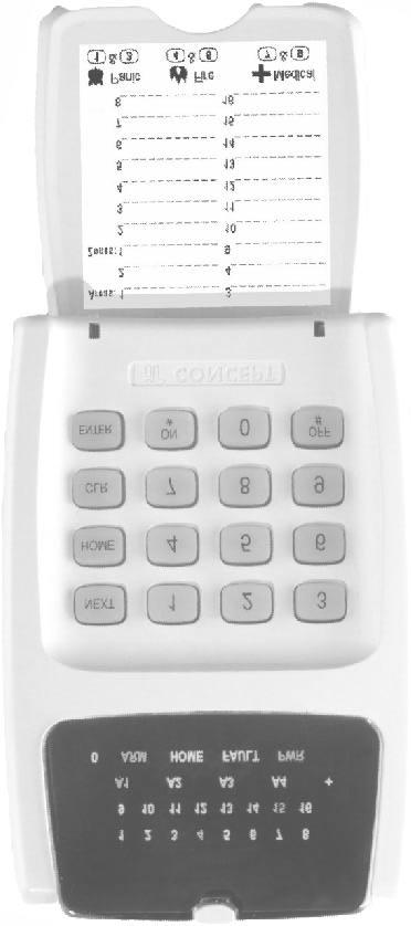
6 6 Version 1.03 January SPECIAL KEY FUNCTIONS 2. The LED Terminal NEXT HOME -Select a Master User operation. (Enter PIN code, press <NEXT> then the Mode number. -Used to Arm the system, or an individual Area, in Home Mode. Master User: -Used to step through programming Addresses (Users or Telephone numbers) -Used to toggle between Zone Test modes. CLR -Set the data in the current Address to the Factory Default. -Clear the data already entered if you have made a mistake. -Logoff the Terminal. (Exit the current Mode of operation) ENTER -Selects the specified programming Address. (After PIN Code and the Address number have been entered) -Saves the data entered in a programming Address. PANIC. FIRE. MEDICAL. Keys 1 & 3 pressed simultaneously. Keys 4 & 6 pressed simultaneously. Keys 7 & 9 pressed simultaneously. REX. (Request to Exit) <OFF> Key. (Enhanced Terminals only) 2.2 BEEPER INDICATIONS. AUTO-LOGOFF: The Terminal will automatically logoff the operator if there is no keypad activity detected for 30 seconds. 2 or 3 Short Beeps: A User, Master or Installer function was successful. 1 Long Beep: A User, Master or Installer function has been unsuccessful. Continuous Short Beeps*: Entry Delay Timer, Exit Delay Timer or Auto-arm Warning. *NOTE: Single Area systems. All Terminals in the system will beep in response to Exit delay, Entry delay or Auto-arm warnings. Multi-Area systems. Only Terminals associated with a particular Area will beep in response to that Area s warning functions. IMPORTANT NOTE: Terminals not associated with an Area will only beep on Area 1 warning functions.
 When the Zone is Sealed. Area is Dis-armed. FAST: * When there has been an Alarm / Tamper on the Zone. SLOW: * When the Zone has been Isolated.")
7 Version 1.03 January LAMP INDICATIONS. Lamp ON OFF FLASHING ZONE Lamps 1 to 16 AREA Lamps A1, A2, A3, A4 When the Zone is Un-sealed. (If the "Zone activity" option enabled) Area is Armed. (Multi-Area mode only) When the Zone is Sealed. Area is Dis-armed. FAST: * When there has been an Alarm / Tamper on the Zone. SLOW: * When the Zone has been Isolated. There has been an Alarm in the Area. (Multi-Area mode only) ARM HOME FAULT ^ Area/s are armed in normal mode. Area/s are armed in home mode. A system input is currently in alarm. System not armed in normal mode. System not armed in home mode. No system inputs are in alarm. PWR AC mains OK AC mains problem FAST: * A system input has been in alarm and must be acknowledged. SLOW: * When a System Input has been Isolated. ARM & HOME - - System is in "Isolate" mode. (NEXT, 10) FAULT & PWR - - System is in "Master Operations" mode. i.e. NEXT functions. 0 Used to display values in programming mode. NOTES: ^ See "Fault Analysis Lamps" in Chapter 4.6 or the "System Inputs Table". * Alarm indication takes priority over Isolate indication.
8 8 Version 1.03 January User Operations 3.1 QUICK ARMING. (If enabled in your system) SINGLE AREA SYSTEM: Enter Area number;, to Arm the system. Enter Area number;, to Arm the system in Home Mode. MULTI-AREA SYSTEM: Enter Area number;, to Arm the system. Enter Area number;, to Arm the system in Home Mode. NOTE: If the Terminal is in Single Area Mode, only the Associated Area can be Armed. 3.2 ARMING / DISARMING A SINGLE-AREA SYSTEM. Arming with PIN code (If enabled in your system) Enter PIN;..., to Arm the system. Enter PIN;..., to Arm the system in Home Mode. Disarming the system Enter PIN;..., to Dis-arm the system. 3.3 ARMING / DIS-ARMING AREAS IN A MULTI-AREA SYSTEM. Each LED keypad can be configured for Single-Area Mode or Multi-Area Mode. The Lamps A1, A2, A3 & A4 show when each Area is Armed. Arming the system. Enter PIN;..., Single Area Mode Arms Area assigned to the Terminal. Multi-Area Mode Arms all Areas in the User s Area List. Enter PIN;...,, Arms all Areas in the - User s Area List. Dis-arming the system. Enter PIN;..., Dis-arms Area assigned to the Terminal. Dis-arms all Areas in the User s Area List. Enter PIN;...,, Arms all Areas in the - User s Area List.
9 Version 1.03 January ARMING / DIS-ARMING INDIVIDUAL AREAS IN A MULTI-AREA SYSTEM. The LED keypad allows the User to Arm and Dis-arm individual Areas in a Multi-Area system. The Lamps A1 A2 A3 A4 show when each area is armed. The procedure for Arming an individual Area is the same for Multi-Area and Single-Area mode. The Area selected must be in the User s Area list. 9 ARM / DISARM Arming the system. Enter PIN;..., Area number, then Dis-arming the system. Enter PIN;..., Area number, then 3.5 ISOLATING (BYPASSING) ZONE INPUTS AND SYSTEM INPUTS NEXT 10 Enter the Isolate Zone mode. (NEXT 10) Enter PIN;..., then,, The <ARM> and <HOME> Lamps will flash together. Isolate / De-Isolate Zone Inputs or System Inputs. Enter the Zone Input or System Input number;... (One to Three digits), then. System Input numbers are listed in the TABLES section at the rear of this manual. When a Zone Input is Isolated, the <Zone Lamp> will flash slowly. When any System Input is Isolated the <FAULT> Lamp will flash slowly. To Isolate or De-Isolate more Inputs, simply repeat this step for each Input. An Isolated Zone Input is De-Isolated by following the same procedure. When the Input is De-isolated, the Zone Lamp slow flashing will stop. Isolated System Inputs can only be De-Isolated by the Installer or a Master User Code. (NEXT 90) Exit the Isolate Zone mode. Press
10 10 Version 1.03 January EMERGENCY ALARM ACTIVATION. -PANIC, FIRE AND MEDICAL ALARMS. Depending on the configuration of the Emergency Alarm options, each different Emergency alarm can activate the Siren and/or the Dialer communications. Consult with the Installer to detemine how each Emergency Alarm will operate. The Emergency Alarms are activated by pressing two specific keys on the Terminal keypad simultaneously. PANIC and keys pressed at the same time. FIRE and keys pressed at the same time. MEDICAL and keys pressed at the same time. 3.7 PIN CODE DURESS ALARM ACTIVATION. If enabled in your system, this function allows the User to activate the PIN Code Duress alarm while performing any normal LED Terminal operations. When activated, the system sends a silent Duress report to the Central Monitoring Station. No local indication is provided. See additional notes on Page 5. To activate the PIN Code Duress alarm. Simply enter your PIN code at an LED Terminal in the normal manner, but increase the last digit of your PIN by a value of 1. NOTE: If the last digit is a 9, then it becomes 0. e.g. If your PIN code is 3456 then enter If your PIN code is 3579, enter ACKNOWLEDGE ALARMS Note the details of any alarms. When an alarm has occurred, the details of the alarm are displayed on the LED Terminal: - The Zone Lamps will flash fast to indicate the Zone (or Zones) that are in alarm. - The Area Lamps will flash to indicate the Area (or Areas) in which the alarm has ocurred. Dis-Arm the System. Follow the normal procedure for Dis-Arming the System. NOTE: In a Multi-Area System, the Area in which the Alarm has occurred must be Dis-Armed. Acknowledge the Alarms. Enter PIN;..., Performing this operation when the System is Dis-Armed will acknowledge the alarms. i.e. Clear the alarms from the display.
11 Version 1.03 January Master User Operations 4.0 ACCESSING THE OPERATIONAL MODES. The Default Master Code is (Or is system is configured for 6 Digit PIN codes) This Code should be changed as soon as possible after installation. When choosing a new Master Code, ensure that a PIN code is chosen that will not be forgotten, while still providing security against unauthorised access. Master User Operations require the User to Access a number of different Operational Modes. This is done by entering a valid Master PIN code, then pressing the <NEXT> key before selecting the 2-digit Mode number. e.g. Enter PIN;..., then, then the Mode number;, This key sequence must be used to access all Operational Modes described in this section. The descriptions of each operation will only show the key sequence <NEXT>, n, n. when showing how to access the Operational mode required. Remember that this is preceded by the PIN code. Master Operations Mode Indication. The <FAULT> and <PWR> Lamps will flash together to indicate that the system is in Master User Operational Modes. Exiting the Master User Operations. Press to exit any of the Master Operations. 4.1 Adding / Changing / Deleting Users.... NEXT View history.... NEXT Walk test mode.... NEXT Setting the Real-Time Clock.... NEXT Auxiliary Control and Test mode.... NEXT Fault Analysis mode.... NEXT Zone Self Test display.... NEXT Edit Telephone numbers.... NEXT View Sofware Version number.... NEXT Acknowledge Door Alarms.... NEXT De-Isolate System Inputs.... NEXT Test Siren speaker and Strobe (Aux. 1).... NEXT Battery Test.... NEXT Test Transmission. (Test report)... NEXT Day Alarm on / off... NEXT Reset Latching Auxiliaries.... NEXT Answer Phone... NEXT Reset Smoke Detectors.... NEXT 99
12 12 Version 1.03 January ADDING / CHANGING / DELETING USERS. NEXT 20 ADDING OR CHANGING A USER 1. Enter the User Editing Mode. Press,,. 2. Enter the User number to be changed. Press, then the User number (User 2 to User 47), then The User number will be displayed on the Terminal via the Zone Lamps. NOTE: If the User number is greater than 16, the first digit will be displayed via a flashing Zone Lamp. If you need to check the User number, press to view the second digit. 3. Enrol the User s Access Card. (If required) Present the Card at any Access Reader in the system within 30 seconds of selecting the User number. Three short beeps will sound to confirm that the Card has been enrolled and assigned to the selected User. If the Card is already assigned to another User, or is not recognised by the system, one long beep will sound to indicate a problem. 4. Enter the new PIN Code. Press, then the new PIN number... (4 or 6 digits), then Three short beeps will sound to confirm the PIN number has been programmed. If the PIN is rejected, one long beep will sound to indicate a problem. 5. Assign the User Type. Press Press, then the new User Type number, then USER TYPE: 0 Arm only Can only Arm the system. 1 Arm/Dis-arm Can Arm and Dis-arm the system. 2 Arm/Dis-arm/Isolate Can Arm/Dis-arm the system and Isolate Zones. 3 Master Can perform all operations above & Master User Operations. 2 beeps will sound to confirm the new User Type has been programmed.
13 Version 1.03 January Assign the User Area or Areas. (Only required if you have a Multi-Area System) Press (A long beep will sound if the System is not in Multi-Area mode) Then for each Area that is to be assigned to this User, Press, then an Area option number, then OPTION: 0 All Areas De-selected. 1 General Area (Single Area Mode) or Area 1 (Multi-Area Mode) selected. 2 Area 2 selected 3 Area 3 selected 4 Area 4 selected When access control is provided, Area assignment also detemines which Doors a User may access. Access is only granted at Door/s associated with the User s Area/s. 2 beeps will sound to confirm the new Area Option has been selected. e.g. If Area 1 and Area 3 are to be assigned to the User; Press <*>, 1, <ENTER>; <*>, 3, <ENTER>. To change another user simply repeat steps 2 to 7. ADD / DELETE USERS DELETING A USER 1. Enter the User Editing Mode. Press,,. 2. Enter the User number to be changed. Press, then the User number (User 2 to User 47), then The User number will be displayed on the Terminal. 3. Delete the User. Press, then to delete the PIN code and/or Card data for this User number.
14 14 Version 1.03 January VIEW HISTORY. NEXT Enter the View History Mode. Press,,. The most recent event will be displayed first. Up to 128 Events are stored in the History. 2. View the other Events. Press Press to view the Next Event. to view the Previous Event. If the are no further events to be displayed, one long beep will sound. History Event Types. Arm Armed in Home Mode Dis-arm Zone Input in alarm System Inputs in alarm <ARM> Lamp. <HOME> Lamp. <ARM> and <0> Lamp. <Zone 1> to <Zone 16> Lamp. <0> Lamp. 4.3 ZONE TEST. NEXT Enter the Zone Alarm Test Mode. Press,,. In Alarm Test Mode, any Zone Input in the Terminal s Associated Area that goes into the Alarm (or Un-sealed) state will cause: - The corresponding Zone Lamp to fast flash. - The Siren to sound for 3 seconds. - The Terminal beeper to emit a short beep. 2. Select Zone Tamper Test. Press to switch between Alarm Test Mode and Tamper Test Mode. In Tamper Test Mode, any Zone Input in the Terminal s Associated Area that goes into the Tamper state will cause: - The corresponding Zone Lamp to slow flash. - The Siren to sound for 3 seconds. - The Terminal beeper to emit a short beep. NOTES: While in the Zone Test Mode, the <HOME> key can be used to toggle between the Alarm Test Mode and the Tamper Test Mode at any time.
15 Version 1.03 January SET THE REAL-TIME CLOCK. NEXT Enter the Real-Time Clock Programming Mode. Press,,. 2. Enter the current Time and Date. Press, then the Time & Date data:... (11 digits), then The date and time are stored in the following order: mm:hh ; DD:MM:YY ; d i.e. Minute, Minute; Hour, Hour; Day, Day; Month, Month; Year, Year; Day Of Week: TIME & DATE Minute (00-59) Hour (00-23) Day (01-31) Month (01-12) Year (00-99) DAY OF THE WEEK Sunday 1 Monday 2 Tuesday 3 Wednesday 4 Thursday 5 Friday 6 Saturday 7 e.g. TIME & DATE: DATA STRING: 1) 07:24 AM, Monday, June 5, ,4,0,7,0,5,0,6,0,1,2, <ENTER> 2) 05:15 PM, Thursday, September 20, ,5,1,7,2,0,0,9,0,1,5, <ENTER> 3. View the current Time and Date. After entering the Real Time Clock Programming Mode, the first digit (Tens of seconds) of the Time and Date Data will be displayed on the Terminal Zone Lamps. Press the key to step through the 13 digits in the Time and Date Data. e.g. Using the Time and Date in Example 1 above, the following data will be displayed: <NEXT> 23 1st digit of Seconds will be displayed. <NEXT> 2nd digit of Seconds will be displayed. <NEXT> 2 will be displayed. (minute) <NEXT> 4 will be displayed. (minute) <NEXT> 0 will be displayed. (hour) <NEXT> 7 will be displayed. (hour) etc. When the end of the data is reached, a long beep will sound to indicate there are no more characters to display, and the first digit will again be displayed. IMPORTANT NOTE: In the event that power is completely removed from the Control Module (i.e. Both the AC input and the Battery are disconnected), when power is restored, the Real-Time Clock will need to be re-programmed to the current Time and Date
16 16 Version 1.03 January AUXILIARY CONTROL AND TEST MODE. NEXT Enter the Auxiliary Control and Test Mode. Press,,. 2. Change the State of an Auxiliary Output. Enter the Auxiliary Output number then Press: to turn the Auxiliary ON. OR to turn the Auxiliary OFF. (1 or 2 digits); If necessary (e.g. When testing the Auxiliary), remember to return the Auxiliary to it s original state before exiting Auxiliary Control and Test Mode. 4.6 FAULT ANALYSIS MODE. NEXT Enter the Fault Analysis Mode. If the <FAULT> Lamp is ON, Press,,. The Zone Lamps on the Terminal are used to display the Faults and Alarms. See following table. 2. Note the details of any System Inputs currently still in Alarm. System Inputs that are currently in Alarm will be indicated by Fast flashing on the relevant Zone Lamp. These Alarms cannot be acknowledged until the problem is rectified. 3. Acknowledge any previous Faults and Alarms. Press. System Inputs that have been in Alarm but subsequently restored since the last Acknowledgement will be indicated by Slow flashing on the relevant Zone Lamp. Note the datails of the Alarm/s displayed. Press to Acknowledge and Clear any of the Faults or Alarms that are not currently in Alarm. This will also cancel the Siren if activated. When a Fault or Alarm has been Acknowledged, the corresponding Zone Lamp will be turned OFF. If all System Inputs have been Acknowledged the <FAULT> Lamp will be turned OFF. IMPORTANT NOTES: 1) Press to toggle between the Current Alarms & Previous Alarms displays. 2) Zone self test (Lamp 10) can only be cleared from Zone Self Test Display Mode (NEXT 26). 3) Door Alarm (Lamp 15) can only be cleared from Acknowledge Door Alarms Mode (NEXT 29).
17 Version 1.03 January FAULT ANALYSIS LAMPS LAMP 1 AC Fail. 2 Low battery. 3 Cabinet Tamper. 4 Siren monitor. 5 PWR fuse. 6 Battery fuse. 7 Comms fail. 8 System reset. 9 Keypad lockout. 10 Zone self test. 11 Keypad Medical Alarm. 12 Keypad Panic Alarm. 13 Keypad Duress Alarm. 14 Keypad Fire Alarm. 15 Door Alarm. 16 Program Change. 4.7 ZONE SELF TEST DISPLAY. NEXT Enter the Zone Self Test Display Mode. If a Zone Input fails the Zone Self Test, the <FAULT> Lamp will be displayed on the Terminal. Fault Analysis Mode (NEXT 25) will also display the Zone Self Test fail Lamp (Zone 10). To view the Zone or Zones that have failed the Zone Self Test, Press,,. 2. Note the details of any Zones that have failed the Zone Self Test. The Zone 1 to Zone 16 Lamps will indicate any Zones that have failed the Zone Self Test so that appropriate action may be taken. e.g. A detector fault may need to be rectified by the Installer. FAULT ANALYSIS 3. Acknowledge the Zone Self Test fault. Press to acknowledge any Zone Self Test faults. When a Zone Self Test fault has been acknowledged, the corresponding Zone Lamp will turn OFF, and the Zone Self Test fail Lamp <Zone 10> in Fault Analysis Mode will also be cleared. If all System Inputs have been acknowledged the <FAULT> Lamp will be turned OFF.
18 18 Version 1.03 January PROGRAM THE TELEPHONE NUMBERS. NEXT Enter the Telephone number programming Mode. Press,,. 2. Program the new Primary Telephone number. Press, then the Telephone number... (Up to 15 digits), then The digits are entered according to the following table. Telephone number digit to program: 0 to 9 # * Pause (1 Second) Key to Press on keypad: 0 to 9 # * <NEXT> Value displayed on Zone Lamps: 0 to e.g. Telephone number: 1 Pause is entered by the key sequence: <*>, 1, <NEXT>, 1, 2, 3, 4, 5, 6, 7, 8, <ENTER> If a mistake is made while keying in the Telephone number digits, press entered and start keying in the number again. to clear all the digits 3 beeps will sound to confirm the new Telephone number has been programmed. If the Telephone number was rejected, one long beep will sound to indicate a problem. 3. View the Telephone number. After entering the Telephone number Programming Mode, Press The first digit of the Telephone number will be displayed on the Terminal Zone Lamps. Press the key to step through all the digits in the Time and Date Data. e.g. Using the Telephone number example 1 Pause , the following data will be displayed: <ENTER> 1 will be displayed. <NEXT> 12 will be displayed. <NEXT> 1 will be displayed. <NEXT> 2 will be displayed. etc. When the end of the Telephone number is reached, 3 short beeps will sound to indicate there are no more digits to display, and the first digit (1 in this example) will again be displayed. 4. Program a new Secondary Telephone number. (Optional) Press and wait for the Terminal to sound a short beep. Press, then the Telephone number... (Up to 15 digits), then
19 Version 1.03 January The digits are entered in the same manner as described for the Primary Telephone number. If a mistake is made while keying in the Telephone number digits, press to clear all the digits entered and start keying in the number again. 3 beeps will sound to confirm the new Telephone number has been programmed. If the Telephone number was rejected, one long beep will sound to indicate a problem. While in the Secondary Telephone number programming Mode, the number can be viewed as described in Step Program a new Callback Telephone number. (Optional) Press and wait for the Terminal to sound a short beep. The Callback Telephone number is Programmed and Viewed as described for the Primary and Secondary Telephone numbers. After the Callback number has been Entered and/or Viewed, pressing Primary Telephone number programming if required. Otherwise, press to exit Telephone number programming. again will return to A long beep will sound indicating that there are no more phone numbers to program. 4.9 VIEW THE SOFTWARE VERSION NUMBER. NEXT Enter the View Software Version number Mode. To view the current Software Version number on the Terminal, press,,. The 1st digit of the 4-digit Version number is displayed by the corresponding Zone Lamp flashing. 2. View the Software Version number. To display each of the remaining digits of the Version number press the key. When the last digit is displayed, and the <NEXT> key is pressed, a long beep will sound and the first digit will again be displayed. e.g. If the version number is V <NEXT>, 2, 8. Zone 1 will be flashing <NEXT> 0 will be flashing <NEXT> 0 will be flashing <NEXT> Zone 3 will be flashing <NEXT> Long beep will sound and Zone 1 will be flashing again.
20 20 Version 1.03 January ACKNOWLEDGE DOOR ALARMS. NEXT Enter Acknowledge Door Alarm Mode. If Zone Lamp 15 on the Terminal indicates a Door Alarm when in Fault Analysis Mode (NEXT 25), one or more Door Alarms need to be acknowledged. Press,,. 2. Acknowledge any Door Alarms. Door Alarms will be indicated by the relevant Zone Lamp 1 to 4. Note the datails of the Alarm/s displayed. Press to Acknowledge any Door Alarms. When a Door Alarm has been Acknowledged, the corresponding Zone Lamp will be turned OFF. If all System Inputs have been Acknowledged the <FAULT> Lamp will be turned OFF.
21 Version 1.03 January DE-ISOLATE SYSTEM INPUTS. NEXT 90 When necessary, System Inputs may be manually isolated (via NEXT 10). This might be the case when a system fault has been detected, appropriate action is being taken and the Alarm no longer needs to be displayed. If any System Inputs are Isolated, this is indicated by the <FAULT> Lamp Slow Flashing. When the fault has been rectified, this operation allows any Isolated System Inputs to be re-enabled. To De-isolate any System Input that has been manually Isolated, Press,,. The Slow flashing on the <FAULT> Lamp will stop TEST SIREN AND STROBE (AUX. 1) NEXT 91 This operation typically instructs the Control Module to activate the Siren & Strobe for 3 seconds. (Note that Siren and Strobe activation will depend on how the devices are connected and programmed. If in doubt, consult your installer) 4.13 BATTERY TEST. NEXT 92 This operation instructs the Control Module to switch off the battery charger for 5 seconds so the battery voltage can be tested. If the battery is above 11.2V, the Terminal will beep 3 times at the end of the test period. If the battery voltage is low, the Terminal will sound one long beep at the end of the test period and you should contact your installer/maintenance technician. (Note that the system can be programmed by the installer to do an automatic battery test every 8 hours.) 4.14 TEST TRANSMISSION. NEXT 93 This operation will instruct the Control Module to send a test transmission to a central station or a domestic telephone number. When transmitting to a Central Station in Contact ID format, Event Code 602 is sent.
22 22 Version 1.03 January DAY ALARM ON / OFF. NEXT 94 This operation dis-ables and enables the Day Alarm function. If the Day Alarm is programmed to operate then this operation will disable it. If the Day Alarm has been disabled, this operation will re-enable it. NOTE: If Disabling, if the Day Alarm is currently On, it will turn Off. If Enabling, the Day Alarm will turn On for the programmed timer period RESET LATCHING AUXILIARIES. NEXT 96 This operation will reset any Auxiliaries that are a latching type, and any Auxiliaries that are currently On with a timer running. (i.e. Auxiliaries that don t have an Off function programmed.) 4.17 ANSWER PHONE. NEXT 97 This operation will cause the Control Module to answer an incoming telephone line call when connection is required for remote programming. IMPORTANT NOTE: THIS OPERATION IS ONLY TO BE USED WHEN INSTRUCTED TO DO SO BY THE INSTALLER OR MAINTENANCE TECHNICIAN SMOKE DETECTOR RESET. NEXT 99 Smoke Detectors connected to your system may be of the Latching type. These smoke detectors need to be reset after they have been triggered into alarm. This operation instructs the Control Module to activate the Smoke Detector Reset Auxiliary, to perform the reset function on any latching smoke detectors. The Auxiliary will automatically turn off after a time period (usually only a couple of seconds) programmed by the installer. Consult your installer to ascertain whether your system requires use of this operation.
23 Version 1.03 January Telephone Remote Control Consult your installer to ascertain whether your system has Telephone Remote Control enabled. (Telephone Remote Control requires the DTMF Card to be fitted to the Control Module) TELEPHONE KEY FUNCTIONS: The following Telephone Keys are used to perform the specified LED Terminal functions: IMPORTANT NOTE: Use short key presses. If keys are held down they may register as multiple presses. <*> Arm / On <#> Disarm / Off <9> NEXT OPERATION: Call the system and Logon: System Telephone Number:... 1) Dial the telephone number of the system from a Touch-tone (DTMF) telephone or mobile phone. 2) When the Control Module answers you will hear a brief tone. 3) When the line is quiet, enter your PIN Code on the telephone keypad. 4.1) To Arm or Disarm the System: To Arm: -All Areas in your Area List. Press <*> -A specific Area. Press <Area Number>, <*> To Disarm: -All Areas in your Area List. Press <#> -A specific Area. Press <Area Number>, <#> e.g. To Arm Area 2. Press: 2, <*>. The Control Module will then reply with a Status message: - A series of Beeps of the same tone to indicate the operation was successful. - A series of Beeps of 2 different tones to indicate the operation could not be performed. IMPORTANT NOTE: You MUST wait to here the Status message beeps before attempting another command. 4.2) To Control an Auxiliary Output: a) Select Auxiliary Control Mode: Press <9>, then 24 (Auxiliary Control & Test Mode) b) Turn an Auxiliary On: Press <Auxiliary Number>, <*> Turn an Auxiliary Off: Press <Auxiliary Number>, <#> e.g. To Turn Auxiliary 3 Off. Press: 3, <#>. DIAL-UP CONTROL c) Logout of Aux Control Mode: Press <#>. (If this is not done before hanging up, you must wait at least 30 seconds before calling the system again) No Status message beeps are sent for Auxiliary control operations.
24 24 Version 1.03 January Domestic Dialer reporting Consult your installer to ascertain whether your system has Domestic dialing enabled. If the system is programmed to report to a Central Monitoring Station, Domestic dialing cannot be enabled. OPERATION: When the alarm signal is received by the remote Telephone, the Telephone user will hear: - Beeps of the same tone to indicate an Area Opening or Closing event. - Beeps of 2 different tones to indicate an Alarm Event. The alarm is acknowledged by the receiving telephone answering the call. The Telephone User does not have to perform any operation to acknowledge the alarm. Once the alarm signal is heard, the User can simply hang-up the telephone. IMPORTANT NOTE: -Once the receiving telephone has answered the call, the alarm message is regarded as being acknowledged and will not be sent again, regardless of whether a User has heard the alarm signal or not. -This means that if an Answering Machine, Fax machine or similar device answers the call, the alarm will still be regarded as being acknowledged. -If this feature is used, care must be excercised in selecting appropriate telephone numbers to ensure that the alarm signal will be heard by an appropriate User.
25 Version 1.03 January System Inputs Table System Inputs are mapped to the following Input Numbers. ALARM I/P No. Zone Lamp DESCRIPTION AC Fail The AC mains has failed, or has been absent for more than the AC Fail delay time. Low Battery Battery voltage is too low to provide backup power if AC fails. Cabinet Tamper Un-authorised removal of cabinet cover or removal of the cabinet from it's mounting surface. Siren Monitor Alarm The Siren speaker is disconnected from the Control Panel. LAN Fuse fail LAN fuse has blown. Short circuit or over-current condition. Battery Fuse fail Battery fuse has blown. Short circuit or over-current condition. Comms Fail System failed to report. System Reset The system has been powered down and powered up again Keypad Lockout System has registered 5 incorrect PIN code attempts in a row. Zone Self Test Fail One or more Zone Inputs have failed the Zone Self Test Keypad Medical Alm The Medical Alarm has been activated on a Terminal keypad. Keypad Panic Alarm The Panic Alarm has been activated on a Terminal keypad. Keypad Duress Alarm A Duress PIN code has been entered on a Terminal keypad. Keypad Fire Alarm The Fire Alarm has been activated on a Terminal keypad. Programming Change There has been a programming change in the system database Door Alarm. Door "Door Forced" or "Door Held" Condition on Door 1. Door Alarm. Door "Door Forced" or "Door Held" Condition on Door 2. Door Alarm. Door "Door Forced" or "Door Held" Condition on Door 3. Door Alarm. Door "Door Forced" or "Door Held" Condition on Door 4. Test Report A Test report transmission has been sent.
26 26 Version 1.03 January-2002 NOTES
27 Version 1.03 January NOTES
28 28 Version 1.03 January-2002 DISCLAIMER 1. While every effort has been made to ensure the accuracy of this manual, the manufacturer and/or it s agents assume no responsibility or liability for any errors or omissions. Due to ongoing development and product improvements, the contents of this manual are subject to change without notice. 2. This manual describes many optional features that may or may not be utilized in a particular system. Optional features generally require additional programming and/or installation of additional hardware. Consult the Installer for details of features and functions available in your system Inner Range Pty. Ltd. Part Number:
(31/03/05) Version p1. INNER RANGE IQ. Programmer s Manual. Programmer s Manual Inner Range Pty. Ltd. Part Number:
 Version p1. INNER RANGE IQ. Programmer s Manual. Programmer s Manual Inner Range Pty. Ltd. Part Number:") (31/03/05) Version 2.604 p1 Programmer s Manual 2005. Inner Range Pty. Ltd. Part Number: 630047 p2 Version 2.604 (31/03/05) TABLE OF CONTENTS. Programming Methods... 3 1. Introduction 1.1 System Overview...
(31/03/05) Version 2.604 p1 Programmer s Manual 2005. Inner Range Pty. Ltd. Part Number: 630047 p2 Version 2.604 (31/03/05) TABLE OF CONTENTS. Programming Methods... 3 1. Introduction 1.1 System Overview...
Quick Programmer s Manual
 Version 2.604 (31/03/05) p1 Quick Programmer s Manual 2005. Inner Range Pty. Ltd. Part Number: 630048V2 p2 Version 2.604 (31/03/05) TABLE OF CONTENTS. 1. PROGRAMMING FLOWCHART. The following flowchart
CC880/LP880, SC8016. Operators Guide Solution-16, Solution-16 Safecom
 CC880/LP880, SC8016 EN Operators Guide Solution-16, Solution-16 Safecom CC880/LP880, SC8016 Operators Guide EN 2 Copyright Notice Unless otherwise indicated, this publication is the copyright of Bosch
INSTALLATION AND PROGRAMMING MANUAL
 INSTALLATION AND PROGRAMMING MANUAL Contents Section 0. Section 1. Section 2. Section 3. Section 4. Section 5. Section 6. Section 7. Section 8. Section 9. Section 10. Section 11. Section 12. Section 13.
Solution Ultima Series Operators Manual ISSUE 1.00
 Solution Ultima Series Operators Manual ISSUE 1.00 Solution Ultima Series Operators Manual Copyright 1998 by, SYDNEY, AUSTRALIA Document Part Number MA488O DOCUMENT ISSUE 1.00 Printed 16 February 1999
AXI LED USER MANUAL (REV. 1.0)
") Security & Home Automation System AXI LED USER MANUAL (REV. 1.0) CONTENTS PREFACE FEATURES LED KEYPAD OUTLOOK 1.0 LIGHT INDICATION 1 2 4 6 CHAPTER 1: ALARM SYSTEM CONTROL 1.0 USING LED KEYPAD 1.0.1 ARMING
Security & Home Automation System AXI LED USER MANUAL (REV. 1.0) CONTENTS PREFACE FEATURES LED KEYPAD OUTLOOK 1.0 LIGHT INDICATION 1 2 4 6 CHAPTER 1: ALARM SYSTEM CONTROL 1.0 USING LED KEYPAD 1.0.1 ARMING
Alarm Control Panel WIC-16Z4P WIC-5Z2P. User Instructions
 WIC-16Z4P WIC-5Z2P User Instructions Page : 2/14 INDEX # Function Page 1 Add a New User Code 11 2 Arm or Disarm All Areas or Disarm Selected Areas (Partitioned System) 8 3 Arming the System (Away Mode)
Solution 844 Operators Manual ISSUE 1.10
 Solution 844 Operators Manual ISSUE 1.10 Solution 844 Operators Manual Copyright 2001 by, SYDNEY, AUSTRALIA Document Part Number MA406O DOCUMENT ISSUE 1.10 Printed 24 April 2001 This documentation is provided
Solution 880 Operators Manual. Issue 1.00
 Solution 880 Operators Manual Issue 1.00 Solution 880 Operators Manual Copyright 1998 by, SYDNEY, AUSTRALIA Document Part Number MA408O Document ISSUE 1.00 Printed 15 June 1998 This documentation is provided
Destiny Destiny Owners Manual
 Destiny 4100 Destiny 4100 Owners Manual TABLE OF CONTENTS INTRODUCTION Control Panel...3 Detection Devices...3 Telephone Keypads...3 GLOSSARY... 4-5 LOCAL PHONE ACCESS Using Your Telephones As Keypads...6
Contents. Glossary
 Contents Glossary ------------------------------------------------------------------------------------------------------ 6 1. Introduction to the IDS 1632 -------------------------------------------------------------
Solution Ultima 862 Operators Manual ISSUE 1.10
 Solution Ultima 862 Operators Manual ISSUE 1.10 Solution Ultima 862 Operators Manual Copyright 2001 by, SYDNEY, AUSTRALIA Document Part Number MA486O DOCUMENT ISSUE 1.10 Printed 24 April 2001 This documentation
Elite 16D Version 16 Zone Controller Arrowhead Alarm Products Ltd. Operating Guide. Proudly Designed and Manufactured in New Zealand
 6 Elite 16D Version 16 Zone Controller Arrowhead Alarm Products Ltd Operating Guide 1 Proudly Designed and Manufactured in New Zealand CONTENTS Page No. INTRODUCTION 3 About your Alarm 3 OPERATING YOUR
Control/Communicator Installation Manual
 DAS NETWORX NX-12 Control/Communicator Installation Manual General Description...2 Ordering Information...2 Option Definitions...3 Programming the LED Code Pads...5 Programming the NX-12...9 Types of Programming
NESS 5000 SERIES DIALLER
 NESS 5000 SERIES DIALLER INSTALLATION MANUAL This manual is designed to provide the installation instructions on the NESS SECURITY PRODUCT'S 5000 SERIES Dialler. For complete details on the warranty or
Solution 4+4 Operators Manual ISSUE 1.25
 Solution 4+4 Operators Manual ISSUE 1.25 Solution 4+4 Operators Manual Copyright 1997 by, SYDNEY, AUSTRALIA Document Part Number MA400O Document ISSUE 1.25 Printed 02 August 1999 This documentation is
ICP-CC408 ICP-CC408 EN. Control Panel. User s Guide
 ICP-CC408 EN User s Guide ICP-CC408 Control Panel ICP-CC408 User's Guide Notices EN 2 Copyright Notice Unless otherwise indicated, this publication is the copyright of Bosch Security Systems, Inc, ( Bosch
Elite 64 Version 64 Zone Controller Arrowhead Alarm Products Ltd. Operating Guide. Proudly Designed and Manufactured in New Zealand
 2 Elite 64 Version 64 Zone Controller Arrowhead Alarm Products Ltd Operating Guide Proudly Designed and Manufactured in New Zealand 1 CONTENTS Page No. INTRODUCTION 3 About your Alarm 3 OPERATING YOUR
User s Information Guide R2A
 Pi HSC505 Home Security Controller User s Information Guide R2A Page 1 of 15 of its development program. 1This document and product are copyrighted and all rights are reserved. Introduction Convention
DL150 DOWNLOADABLE CONTROL COMMUNICATOR INSTALLATION MANUAL
 DL150 DOWNLOADABLE CONTROL COMMUNICATOR INSTALLATION MANUAL TABLE OF CONTENTS 1. GENERAL DESCRIPTION... 2 2. STANDARD AND OPTIONAL PARTS LIST... 2 3. FEATURE DEFINITIONS... 3 4. TERMINAL DRAWING AND SPECIAL
Watchguard WGAP864 User Manual
 Watchguard WGAP864 User Manual v1.0 Issued September 2016 1 2 Table of Contents Glossary... 5 1. Introduction to your Watchguard WGAP864... 6 2. Before Operating your Alarm System... 6 3. Understanding
IDS S E C U R I T Y IDS816. User Manual MANUAL NO C ISSUED APRIL 2005 VERSION 2.00
 INHEP DIGITAL IDS S E C U R I T Y IDS816 User Manual MANUAL NO. 700-283-01C ISSUED APRIL 2005 VERSION 2.00 Contents 1. Introduction to the IDS816... 4 2. Understanding the Keypad Indicators... 4 3. Programmable
ICP-CC488 ICP-CC488 EN. Control Panel. User s Guide
 ICP-CC488 EN User s Guide ICP-CC488 Control Panel ICP-CC488 User's Guide Notices EN 2 Copyright Notice Unless otherwise indicated, this publication is the copyright of Bosch Security Systems, Inc. ( Bosch
IDS S E C U R I T Y IDS816. User Manual MANUAL NO B ISSUED DEC 2004 VERSION 2.00
 INHEP DIGITAL IDS S E C U R I T Y IDS816 User Manual MANUAL NO. 700-283-01 B ISSUED DEC 2004 VERSION 2.00 Contents 1. Introduction to the IDS816... 4 2. Understanding the Keypad Indicators... 4 3. Programmable
HILLS Series LED Code Pad User Manual
 HILLS Series LED Code Pad User Manual Not all features may be available on your system Check with your installer to find out which features are programmed Page 2 TABLE OF CONTENTS Code Pad Diagrams...2
L900 series USER MANUAL
 INTRODUCTION The BLUGUARD Control Panel is designed for simple operation yet provides the maximum protection for you. Please read this manual carefully and follow the instructions contained in this book.
Using Your. Security System With LED Keypad S5030, S5031, S5032
 Using Your Security System With LED Keypad S5030, S5031, S5032 Contents 1 Overview Your Security System... 1 How Your Security System Works... 2 Your System's Programming... 3 Getting Used to Your System...
Solution 6+6 Wireless - AE Operators Manual ISSUE 1.10
 Solution 6+6 Wireless - AE Operators Manual ISSUE 1.10 Solution 6+6 Wireless - AE Operators Manual Copyright 1997 by, SYDNEY, AUSTRALIA Document Part Number MA660O Document ISSUE 1.10 Printed 02 December
Alarm Control Panel WIC-16Z4P WIC-5Z2P. Installation & Operation User Manual
 WIC-16Z4P WIC-5Z2P Installation & Operation User Manual Page : 1/34 INDEX # Function Page 1 Abort Current Communication and Clear Reporting Queue (*59) 13 2 Abort Current Communications (*59) 10 3 Account
User s Guide. SUB-MA7240O-0001.OG.Solution doc. Created: 6/05/03. Last Updated: 23/09/03. MA7240AO-0001 Version 1.0
 User s Guide SUB-MA7240O-0001.OG.Solution40-111.doc Created: 6/05/03 Last Updated: 23/09/03 MA7240AO-0001 Version 1.0 2 Table Of Contents User List...6 Quick Reference..7 Features...7 Keypad User's Guide...8
Elite S Version 8-16 Zone Controller Arrowhead Alarm Products Ltd. Operating Guide. Proudly Designed and Manufactured in New Zealand
 9 Elite S Version 8-16 Zone Controller Arrowhead Alarm Products Ltd Operating Guide Proudly Designed and Manufactured in New Zealand 1 CONTENTS Page No. INTRODUCTION About your Alarm 3 3 OPERATING YOUR
Control Panel ICP-SOL2-P/ICP-SOL3-P. en User's Guide
 Control Panel ICP-SOL2-P/ICP-SOL3-P en User's Guide Control Panel Table of Contents en 3 Table of contents 1 Introduction 5 2 Specifications 6 3 Codepad Introduction 7 3.1 Codepad 7 3.2 Quick Codepad
CC408. Quick Reference Guide Solution 880
 CC408 EN Quick Reference Guide Solution 880 CC408 Quick Reference Guide Notices EN 2 Copyright Notice Unless otherwise indicated, this publication is the copyright of Bosch Security Systems Pty Ltd ( Bosch
Control Panel ICP-SOL2-P/ICP-SOL3-P. en User's Guide
 Control Panel ICP-SOL2-P/ICP-SOL3-P en User's Guide Control Panel Table of Contents en 3 Table of contents 1 Introduction 5 2 Specifications 6 3 Codepad Introduction 7 3.1 Codepad 7 3.2 Quick Codepad
NetworX NX-8V2. LED Keypad User Manual
 NetworX NX-8V2 LED Keypad User Manual POWER Light is on when AC power is present; flashes to indicate a low battery condition. ARMED Light is on when armed; off when disarmed; flashes to indicate a previous
Contents. Glossary Introduction to the IDS Notes Understanding the Keypad Indicators Operation of the Keypad...
 2 Contents Glossary...7 1. Introduction to the IDS805...8 1.1 Notes...8 2. Understanding the Keypad Indicators...8 3. Operation of the Keypad...9 4. System Information...10 4.1 Programmed Functions...10
IDS816 User Manual H Issued January 2009
 1 Contents Glossary-------------------------------------------------------------------------------------------------------------------6 1. Introduction to the IDS 816---------------------------------------------------------------------------7
Challenger Series Users Manual
 Challenger Series Users Manual P/N MAUSER-TS1016 05 20AUG15 Copyright Trademarks and patents Manufacturer 2015 UTC Fire & Security Australia Pty Ltd. All rights reserved. The Challenger name and logo are
Digiplex System V2.14 / V2.2ACC. Control Panel Programming Guide
 Digiplex System V2.14 / V2.2ACC Control Panel Programming Guide Table of Contents Getting Started...2 What Do I Do First?...2 How Do I Program the Control Panel?...2 Single Digit Entry Method...2 Multiple
PowerWave-16. Users Operating and Programming Guide Version P/N Rev. B N.A July 2002
 ELECTRONIC ENGINEERING LTD. PowerWave-16 16 zone Control panel Communicator Users Operating and Programming Guide Version 6.20 P/N 7121240 Rev. B N.A July 2002 Contents Introduction...4 Meet the Crow Alarm
NETWORX TM. User manual NX-4
 NETWORX TM User manual NX-4 POWER Light is on when AC power is present; flashes to indicate a low battery condition. ARMED Light is on when armed; off when disarmed; flashes to indicate a previous alarm.
Voice Board. Installation and Programming Guide. Runner 4/8,PowerWave 4/8/16 &, Elite64. Add-on Board For Storing Recorded Voice Messages
 ELECTRONIC ENGINEERING LTD. Voice Board Runner 4/8,PowerWave 4/8/16 &, Elite64 Add-on Board For Storing Recorded Voice Messages And listen-in. Installation and Programming Guide. P/N 7101372 Rev. C V.K
Understanding the Code Pad lights...4. Code Pad tones...5. Fully arming the system On MODE...6. Fully arming the system - Quick Arm MODE...
 TABLE OF CONTENTS...Glossary of terms...2...code Pad Diagram...3 Understanding the Code Pad lights...4 Code Pad tones...5 Fully arming the system On MODE...6 Fully arming the system - Quick Arm MODE...6
Control Panel. Operators Manual TO SUIT AS216 KEYPAD. AS216-OM-6.2. Advanced Digital Controls
 Control Panel Operators Manual TO SUIT AS216 KEYPAD AS216-OM-6.2 Ultra-16 Control Panel AS216 OPERATORS MANUAL Copyright 2002 by NZ Ltd Auckland, New Zealand Document Part Number: This document is provided
Summit 3208GLD USER MANUAL. Electronics Line
 Summit 3208GLD USER MANUAL Electronics Line Table of Contents 1: Introduction... 2 2: Overview... 3 3: Keypad Functions... 4 3.1: Keypads... 4 3.2: 3108 LCD Keypad Layout... 4 4: Basic System Operation...
Challenger10 Users Manual
 Challenger10 Users Manual P/N MAUSER-TS1016 REV 01 ISS 18FEB13 Copyright Trademarks and patents Manufacturer Agency compliance Contact information 2013 UTC Fire & Security. All rights reserved. The Challenger
ELT-KLED EliteSuite LED Keypad Installation Manual
 ELT-KLED EliteSuite LED Keypad Installation Manual ELT-KLED EliteSuite Installation Manual PUBLICATION INFORMATION First Publication Draft Document Release Only Updated fire zone information Second Publication
IDS S E C U R I T Y IDS816. User Manual. MANUAL NO A ISSUED November 2004 VERSION 1.00
 INHEP DIGITAL IDS S E C U R I T Y IDS816 User Manual MANUAL NO. 700-283-02A ISSUED November 2004 VERSION 1.00 Contents 1. Introduction to the IDS816... 4 2. Understanding the Keypad Indicators... 4 3.
JA-63 Profi User manual
 JA-63 Profi User manual Contents: 1 Limited warranty... 2 2 Indicators... 3 3 Controlling the system... 4 3.1 Arming... 5 3.2 Disarming... 6 3.3 Panic Alarm... 6 3.4 To stop ALARM... 6 3.5 Home arming...
HARDWIRED CONTROL PANELS
 USER GUIDE 9651 HARDWIRED CONTROL PANELS Contents 1. Introduction...3 The Alarm System...3 The Keypad...3 About This Guide...5 2. Everyday Operation...6 How Do I Know if the System is Working?...6 Setting
NetworX Series NX-1500E LED Keypad
 NetworX Series NX-1500E LED Keypad User Manual SECURITY SYSTEM NOTES Installing/Service Company For Service Call Central Station Duress Code FUNCTION CODES Function Code Controls Function This system
SCORPION Z16040C, Z8040C and Z5120C
 SCORPION Z16040C, Z8040C and Z5120C Alarm Controller User Instructions Thank you for choosing to purchase this micron security alarm controller. Micron product is manufactured to exacting quality standards.
3 User s settings. 3.3 Internal clock setting
 2.9 Subsystem arming In a large building a sub control panel can be enrolled to the JA-63. The subsystem reports all alarms and failures to the main system. The installer can program if the systems will
NookBox Installation Guide Keypad. Installation Guide. NookBox Keypad (P / E )
") 1 Installation Guide NookBox Keypad (P119010 / E6309744) 2 NookBox Keypad (P119010 / E6309744) 3 Parts Identification 1. Active LED 2. Status LED 3. Fault Display LED 4. Arm Key 5. Home Key 6. Key Check
1 Installation Guide NookBox Keypad (P119010 / E6309744) 2 NookBox Keypad (P119010 / E6309744) 3 Parts Identification 1. Active LED 2. Status LED 3. Fault Display LED 4. Arm Key 5. Home Key 6. Key Check
SECURITY SYSTEM NOTES
 SECURITY SYSTEM NOTES Installing/Service Company For Service Call Central Station Duress Code FUNCTION CODES Function Code Controls Function EMERGENCY ACTIVATION KEYS (check if enabled) Fire Auxiliary
TABLE OF CONTENTS TABLE OF CONTENTS 1
 TABLE OF CONTENTS TABLE OF CONTENTS 1 FEATURES 2 Keypad Programmable... 2 EEPROM Memory... 2 Static/Lightning Protection... 2 Supervision... 2 Operation... 2 SPECIFICATIONS 2 PC1550 Control Panel... 2
BENTEL SECURITY srl reserves the right to modify the technical specifications of this product without prior notice.
 BENTEL SECURITY srl reserves the right to modify the technical specifications of this product without prior notice. via Florida - Z.I. Valtesino - 63013 GROTTAMMARE (AP) - ITALY USER MANUAL: Digital communicator
CC488. Quick Reference Guide Solution Ultima 880
 CC488 EN Quick Reference Guide Solution Ultima 880 CC488 Quick Reference Guide Notices EN 2 Copyright Notice Unless otherwise indicated, this publication is the copyright of Bosch Security Systems Pty
Power Wave LCD Keypads. Users Operating and Programming Guide Version 2.00
 Power Wave LCD Keypads CR-16S CR-16M Users Operating and Programming Guide Version 2.00 P/N 7102265 Rev. C N.A May 2003 Contents Introduction...4 Meet the PowerWave Alarm Control System... 4 Typical Alarm
USER CODES. User Codes (1-6 digits) Access Levels + Access Levels. Time Control Address Address Address Address User 1 (Master)
 Access Levels + Access Levels. Time Control Address Address Address Address User 1 (Master)") User Codes (1-6 digits) Access Levels Access Levels + Time Control User 1 (Master) 1 1 2 3 25 49 73 0 User 2 2 26 50 74 0 User 3 3 27 51 75 0 User 4 4 28 52 76 0 User 5 5 29 53 77 0 User 6 6 30 54 78 0
User Codes (1-6 digits) Access Levels Access Levels + Time Control User 1 (Master) 1 1 2 3 25 49 73 0 User 2 2 26 50 74 0 User 3 3 27 51 75 0 User 4 4 28 52 76 0 User 5 5 29 53 77 0 User 6 6 30 54 78 0
ABORT Light flashes during an abort delay time; is on during or after an alarm report to the central station. EMERGENCY ACTIVATION KEYS
 POWER Light is on when AC power is present; flashes to indicate a low battery condition. CHIME Light is on when the chime feature is active. ABORT Light flashes during an abort delay time; is on during
DS7446KP. User Guide. Keypad
 DS7446KP EN User Guide Keypad DS7446KP User Guide Command Quick Reference Command Quick Reference Command Type Basic Arming Commands Advanced Arming Commands System Disarming Commands Command Turn the
Solution 862 Installation Manual ISSUE 1.30
 Solution 862 Installation Manual ISSUE 1.30 MA406I This page has been included for you to cut out and insert into the spine of the folder Solution 862 Installation Manual ISSUE 1.30 (61-2) 9672 1233 Solution
Challenger Version 8 Programming Relays.
 Challenger Version 8 This document provides details of the programming requirements for activating relays on the Challenger system. The following are some of the applications that Challenger Relays may
GE Security. Challenger V8 & V9. User Manual
 GE Security Challenger V8 & V9 User Manual Copyright Disclaimer Trademarks and patents Intended use Copyright 2008, GE Security Pty. Ltd.. All rights reserved. This document may not be copied or otherwise
D6500 reports are shown in typewriter style letters. For example, AC FAILED indicates the report sent when the panel reports an AC power failure.
 Notice The material and instructions covered in this manual have been carefully checked for accuracy and are presumed to be reliable. However, Radionics, Inc. assumes no responsibility for inaccuracies
IDS800 USER MANUAL. Summary of Operation. + [ ] 2 IDS800 USER MANUAL NO K ISSUED APR 2003 VER 1.44
![IDS800 USER MANUAL. Summary of Operation. + [ ] 2 IDS800 USER MANUAL NO K ISSUED APR 2003 VER 1.44](/thumbs/89/98095999.jpg "IDS800 USER MANUAL. Summary of Operation. + [ ] 2 IDS800 USER MANUAL NO K ISSUED APR 2003 VER 1.44") Summary of Operation A rm/ disarm [#] + [USER CODE] Quick Quick Quick Away Arm Stay Arm Stay Arm & Go H old down [ 1] for 1 second H old down [ 5] for 1 second H old down [ 6] for 1 second Panic Fire Medical
Summary of Operation A rm/ disarm [#] + [USER CODE] Quick Quick Quick Away Arm Stay Arm Stay Arm & Go H old down [ 1] for 1 second H old down [ 5] for 1 second H old down [ 6] for 1 second Panic Fire Medical
TABLE OF CONTENTS. FOR THE RECORD 15 PROGRAMMING WORK SHEETS 16 CONTROL PANEL WIRING DIAGRAM inside back cover
 TABLE OF CONTENTS FEATURES 2 SPECIFICATIONS 2 INSTALLATION 3 Mounting the Panel... 3 Mounting the Keypad... 3 Auxiliary Power Connection... 3 PGM Terminal Connections... 3 Bell/Siren Connection... 3 Keypad
MG Partition 64-Zone Wireless Console with GPRS/GSM Version 1.6. Section Programming Guide
 MG6250 2-Partition 64-Zone Wireless Console with GPRS/GSM Version.6 Section Programming Guide Things You Need to Know About this Programming Guide The MG6250 All-in-one Wireless Console can be programmed
Security System. User Guide for the LED Command Center
 Security System User Guide for the LED Command Center National Security Systems Inc (800)457-1999 MY SECURITY COMPANY IS: CALL BEFORE TEST: THIS SECURITY SYSTEM IS CONNECTED TO TELEPHONE NUMBER: THE SECURITY
2000 Series. Program Entry Guide. Control Panels
 2000 Series EN Program Entry Guide Control Panels 2000 Series Program Entry Guide About This Manual EN 2 About This Manual This guide describes the programming parameters available to the 2000 Series Control
HA-263K HA-263D. OWNER'S MANUAL Installation And Operation 8-ZONE ALARM CONTROL PANEL FOR HOME AND OFFICE PROTECTIONS OPEN THE CABINET FOR SERVICE
 D (OPERATION) INITIATE A DYNAMIC BATTERY TEST The system tests the back-up battery once every 24 hours. The owner can initiate a dynamic battery test at any time with the following codes while the system
The Icon Series. User Guide. CDV25 Version 1.0. Iconopm1.pm
 The Icon Series User Guide CDV25 Version 1.0 Iconopm1.pm6 200198 The Icon Series The Icon Series The Icon Series Contents Contents 2 Terms you need to Know 3 Keypad Indicators 4 Keypad Keys 5 User Functions
Challenger10 Administrators Manual
 Challenger10 Administrators Manual P/N MAADMN-TS1016 REV 01 ISS 18FEB13 Copyright Trademarks and patents Manufacturer Agency compliance Contact information 2013 UTC Fire & Security. All rights reserved.
DESTINY 6100 SERIES SECURITY SYSTEM OWNER S MANUAL V1 12/01
 DESTINY 6100 SERIES SECURITY SYSTEM OWNER S MANUAL 800-6006V1 12/01 System Overview General Information Control Panel Detection Devices You have made a wise decision to protect your family and property
All-In-One Wireless Security System V3.2 Programming Guide. Model # MG6130 / MG6160
 All-In-One Wireless Security System V3.2 Programming Guide Model # MG6130 / MG6160 We hope this product performs to your complete satisfaction. Should you have any questions or comments, please visit www.paradox.com
Wireless Keypads LKP(E)S8M Series
S8M Series") Wireless Keypads LKP(E)S8M Series User manual Contents Congratulations on your purchase of this Honeywell wireless keypad. To make the best out of your equipment we advise you to read this manual carefully.
Wireless Keypads LKP(E)S8M Series User manual Contents Congratulations on your purchase of this Honeywell wireless keypad. To make the best out of your equipment we advise you to read this manual carefully.
X64 Wireless Training
 X64 Wireless Training IDS Contents 1 Contents Features 3 Wireless Hardware 4 IDS & Duevi integration PCB 5 LED operation 5 Wireless Device Hardware setup 6 Location 260 7 LED Keypad Instructions 7 Adding
Digiplex LED Keypads User s Manual
 KLEDEU03.fm Page -1 Friday, May 4, 2001 11:25 AM Digiplex LED Keypads User s Manual KLEDEU03.fm Page 0 Friday, May 4, 2001 11:25 AM KLEDEU03.fm Page 1 Friday, May 4, 2001 11:25 AM TABLE OF CONTENTS 1.0
DESTINY OWNER S MANUAL
 DESTINY OWNER S MANUAL DESTINY You have made a wise decision to protect your family and property with the DESTINY Security System. The DESTINY has been designed to provide you with a maximum level of security
The Challenger Version 8 User Guide
 The Challenger Version 8 User Guide CONTENTS Function included in your system Introduction...4 Glossary... 6 The Challenger Console.. Liquid Crystal Display... 9 Keypad...10 Indicator Lights...11 User
Solution 6+6 Wireless - AE Installation Manual ISSUE 1.10
 Solution 6+6 Wireless - AE Installation Manual ISSUE 1.10 MA660I Solution 6+6 This page has been included for you to cut out and insert into the spine of the folder Wireless AE Installation Manual ISSUE
4-PGM Expansion Module
 4-PGM Expansion Module APR3-PGM4 = Default setting SECTION [001] : General Options SECTION [002] : PGM Options Option OFF ON Option OFF ON [1] Future Use N/A N/A [1] PGM1 Deactivation After Deactivation
8 plus and16 plus. User s Guide * # ent. esc GALAXY 16+ V2.XX TUE 30 JUN. IU ZST 962 Issue 2. A u B u
 8 plus and16 plus User s Guide GALAXY 16+ V2.XX 06.22 TUE 30 JUN 1 2 3 4 5 6 7 8 9 0 * # A u B u ent esc IU1-0018 ZST 962 Issue 2 Contents INTRODUCTION... 1 Glossary of Terms... 3 KEYPAD INFORMATION...
WIRELESS ALARM SYSTEM WITH TELEPHONE AUTO DIALER
 BAT.LOW AC WIRELESS ALARM SYSTEM WITH TELEPHONE AUTO DIALER THE SYSTEM THAT CALLS YOU! Our WIRELESS ALARM SYSTEM WITH TELEPHONE AUTO DIALER is designed to allow you to create your own security system.
RANGER 8600 DOWNLOADABLE CONTROL COMMUNICATOR INSTALLATION MANUAL
 RANGER 8600 DOWNLOADABLE CONTROL COMMUNICATOR INSTALLATION MANUAL TABLE OF CONTENTS GENERAL DESCRIPTION... 2 STANDARD AND OPTIONAL PARTS LIST... 2 PARTS DIAGRAM... 3 TERMINAL DRAWING AND SPECIAL NOTES...
Protégé Eclipse LED Keypad User Manual PRT-KLES
 Protégé Eclipse LED Keypad User Manual PRT-KLES The specifications and descriptions of products and services contained in this manual were correct at the time of printing. Integrated Control Technology
The most user friendly Security Alarm System L S Section 1 Overview of System Section 2 Planning your Installation
 The most user friendly Contents Section 1 Overview of System 1.1 Kit Contents 1.2 Tools Required 1.3 System Features Security Alarm System L S 4 0 0 Section 2 Planning your Installation 2.1 Location of
MG5000 V2.4 MG5050 V2.4 SP5500 V2.4 SP6000 V2.4 SP7000 V2.4. Programming Guide
 MG5000 V2.4 MG5050 V2.4 SP5500 V2.4 SP6000 V2.4 SP7000 V2.4 Programming Guide We hope this product performs to your complete satisfaction. Should you have any questions or comments, please visit www.paradox.com
RUNNER 8/64. 8/64 Zones Control Panel. Program Summary Guide
 RUNNER 8/64 8/64 Zones Control Panel Program Summary Guide SOFTWARE VERSION This manual relates to RUNNER 864 control panels with software version V10.0.115 and above Special Programming Operating Procedures
Security System. User s Guide for the Text Command Center
 User s Guide for the Text Command Center MY ALARM COMPANY IS: CALL BEFORE TEST: THIS SECURITY SYSTEM IS CONNECTED TO TELEPHONE NUMBER: THE SECURITY CONTROL PANEL IS CONNECTED TO THE PHONE JACK LOCATED:
THE OPERATOR ACCESSING YOUR SYSTEM 3 FUNCTIONS OF THE "OPERATOR" 4 PROGRAMMING/CHANGING ACCESS CODES 13 ACTIVATING EMERGENCY ALARMS 14
 THE OPERATOR INTRODUCTION 3 ACCESSING YOUR SYSTEM 3 FUNCTIONS OF THE "OPERATOR" 4 SECTION I. CHECKING SYSTEM STATUS 4 SECTION II. USING THE MENU 5 SECTION III. ARMING YOUR SECURITY SYSTEM 6 SECTION IV.
Intruder alarm system Operating Instructions
 Intruder alarm system Operating Instructions 0 2 3 4 5 6 7 8 9 CHIME OMIT RESET PROG SET S Power 0 2 3 5 6 7 8 Chime Omit Prog 4 9 Set AccentaG3 mini Servicing organisation details Servicing organisation
RANGER 7600 DOWNLOADABLE CONTROL COMMUNICATOR INSTALLATION MANUAL
 RANGER 7600 DOWNLOADABLE CONTROL COMMUNICATOR INSTALLATION MANUAL TABLE OF CONTENTS 1. TABLE OF CONTENTS... P.1 2. GENERAL DESCRIPTION... P.2... 3. STANDARD AND OPTIONAL PARTS LIST... P.2... 4. FEATURE
HARDWIRED CONTROL PANELS
 USER'S GUIDE HARDWIRED CONTROL PANELS Cooper Security Limited 2007 Every effort has been made to ensure that the contents of this book are correct. However, neither the authors nor Cooper Security Limited
Solution 6+6 Wireless On/Off Installation Manual ISSUE 1.20
 Solution 6+6 Wireless On/Off Installation Manual ISSUE 1.20 MA670I This page has been included for you to cut out and insert into the spine of the folder Solution 6+6 Wireless On/Off Installation Manual
Fire Burglary Instruments Inc. XL-2G Gold Control/Communicator Installation Training Seminar Rev. 5/96
 Fire Burglary Instruments Inc. XL-2G Gold Control/Communicator Installation Training Seminar Rev. 5/96 XL-2G Gold Product Overview 7 Zones (6 programmable + panic or keyswitch zone) Fast Loop Response
Property of Monitronics Inc
 Enter Program Press CODE key + * + 2468 + 1 (also try 2121) Installer Options Move to location Program location Exit Program Default Panel Hex Program Code + * + Installer Code + 1 = Enter Programming
HEXA PROGRAMMING: STREAMLINED SECTION PROGRAMMING
 -961212-0004 SOFTWARE VERSION 3.10 CONTROL PANEL RESET: Installer lock must be unlocked. ( 058: enter any value other than 147) Power down reset (1) Remove battery and AC to power down the unit. (2) Connect
 Solution-6 Operators Manual Page 1 Preface Congratulations on selecting the Solution-6 security control system for your installation. So that you can obtain the most from your unit, we suggest that you