Contents. Glossary
|
|
|
- Herbert Parrish
- 5 years ago
- Views:
Transcription
1
2 Contents Glossary Introduction to the IDS Before Operating Your Alarm System Understanding the Keypad Indicators The Keypad Buzzer Setting the Time Programmable Functions Arming the Control Panel Away Arm Quick Away Arm Stay Arm How to Stay Arm Quick Stay Arm How to Stay Arm and Go Key-switch or Remote Arming (If fitted) Auto Arm Disarming the Control Panel How to Disarm with a User Code How to Disarm using a Key-switch or Remote Bypassing Zones Bypassing/Un-bypassing a Zone Emergency Alarms Fire Alarms Panic Alarms Medical Alarms Duress Alarms Alarm Memory User Codes Adding, Deleting and Editing User Codes How to enter User Program Mode Explanation of Programmable Options Add a New User Code - Option Edit a User Name - Option 1 (LCD Keypads only) Edit a Selected User Code - Option View a User Code Slot Number - Option User Code Properties - Option Explanation of User Code Properties Master Code (Only Adjustable by the Installer)
3 Duress Code Maid's Code Group Arm Code Group Disarm Code Arm Code Disarm Code Report Open and Close User Phone in Access Report User Access Assign User Code to Partitions - Option Adding User Remotes - Option Delete User Code - Option 9 (Code known) Delete a User Code - Option 10 ("Slot" known) Viewing a User Name - Option 11 (Slot known) Stay Zones How to Select a Stay Profile How to Program Stay Zones Buzz Zones How to Program a Buzz Zone Chime Zones How to Program Chime Zones Viewing Trouble Conditions Changing a Partition Output Control via a Keypad Remote Telephone Access Controlling the IDS 1632 via Cellphone SMS Checking the Airtime Balance Recharging/Topping up Airtime Index Tables Table 1 User Programming Options Table 2 User Code Properties Table 3 Trouble Conditions Table 4 Remote Telephone Operation
4 4
5 5
6 Glossary Alarm Memory This is the history of the most recent tampers and violations occurred the last time the system was armed, as well as which zones were bypassed. Arm Arming the system sets the system into the ARMED mode. In this mode, violating a zone will activate an alarm condition. If the system is programmed correctly, this will cause an appropriate reporting code to be sent to the monitoring company. Bypass Bypassing deactivates a zone. When the panel is ARMED, violation of a bypassed zone will be ignored. Disarm Disarming deactivates the system. Fire, medical and panic functions remain active while the system is disarmed. Entry/Exit Zones These are zones that you may pass through during the entry/exit delay period without triggering an alarm. Their purpose is to provide a means by which you can exit after arming the system and a means of getting to the panel to disarm it after gaining access to the premises. Generally the last exit point of the building and the first entry point, this is the front door of the home / business premises, in most cases. Follower Zone A zone that may be temporarily violated during the Exit zone delay period or after violation of an Entry/Exit zone. This allows the user (limited time) access to disarm the system, and sufficient time to exit before arming comes into effect. A Follower zone will behave as per an Instant zone if violated prior to the violation of an Entry/Exit zone. Instant Zone When the system is armed, violation of an Instant Zone will immediately cause an alarm condition to be registered. Master User Master user status (by default attributed to the first User Code) enables this user to add new user codes and alter the properties of codes already in use. Any user may be given Master User Status by selecting the Master User option in the User Code Properties for that User. Partition A partition is a group of zones which may be armed and disarmed independently without affecting zones or users assigned to other partitions. The IDS 1632 Alarm Panel may have been programmed by your installer to have up to 8 partitions. Stay Arm This is an arming mode that allows for certain pre-programmed, STAY zones to be bypassed (temporarily disabled) while the system is armed. If you arm the system and do not leave the premises within the exit delay, the system will assume that you are remaining in the premises, and will stay arm. Stay Arm and Go Arming that allows the user to STAY ARM and leave the premises. 6
7 Stay Zone A zone that is bypassed automatically when the system is STAY ARMED. User Code There may be up to 250 unique user codes. Each has its own set of associated properties (action and access rights) which can only be set by a Master User. By default, the first User Code is a Master User. Violate A zone is violated when a sensor connected to a zone input registers a door opening, a window opening, somebody moving in the room, or glass breaking depending on the sensor for that zone.) Zone A zone is a specific area of your premises monitored by sensors that detect violations (doors/windows opening or people moving) in that area. 1. Introduction to the IDS 1632 The IDS 1632 is a versatile, microprocessor-based sixteen-zone Alarm Panel. There are eight partitions and the panel can be expanded to monitor thirty two burglary zones. Most features are optional and may be programmed directly through the keypad. There is a dedicated Panic zone, monitored siren output, auxiliary power outputs and eight (expandable to twelve) programmable outputs which may be programmed to perform various trigger/switching functions. The panel interfaces with a GPRS module (optional), allowing remote control by SMS, as well as SMS reporting to up to 5 cellphone users. An optional Voice Module reports to the user in English and provides a voice-prompted menu over the telephone. For correct operation these Alarm Panels must be used in conjunction with the specified transformer/battery combination and appropriate peripheral sensors and signalling devices. 2. Before Operating Your Alarm System Read the entire manual carefully and keep it in an accessible place. Note that your security system should be installed and serviced by a qualified security professional who should instruct you regarding the level of protection provided and the operation of the system. Should you have any questions regarding the operation of the system, contact your security company representative. Note that your system should be tested on a regular basis. Before testing the system please notify your security company of your intention to do so. NEVER disconnect the mains power as the back-up battery will eventually discharge thereby causing the control panel to shutdown. Note that a security system cannot prevent emergencies. It is only intended to alert you and (if applicable) your central station, of an emergency situation. Note that smoke and heat detectors may not detect all fire situations. 7
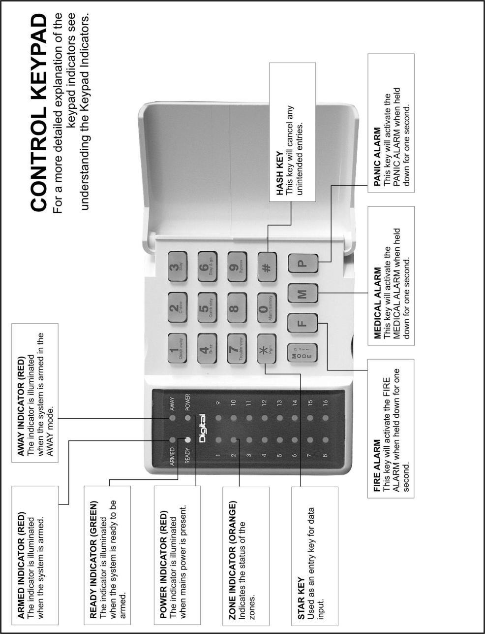
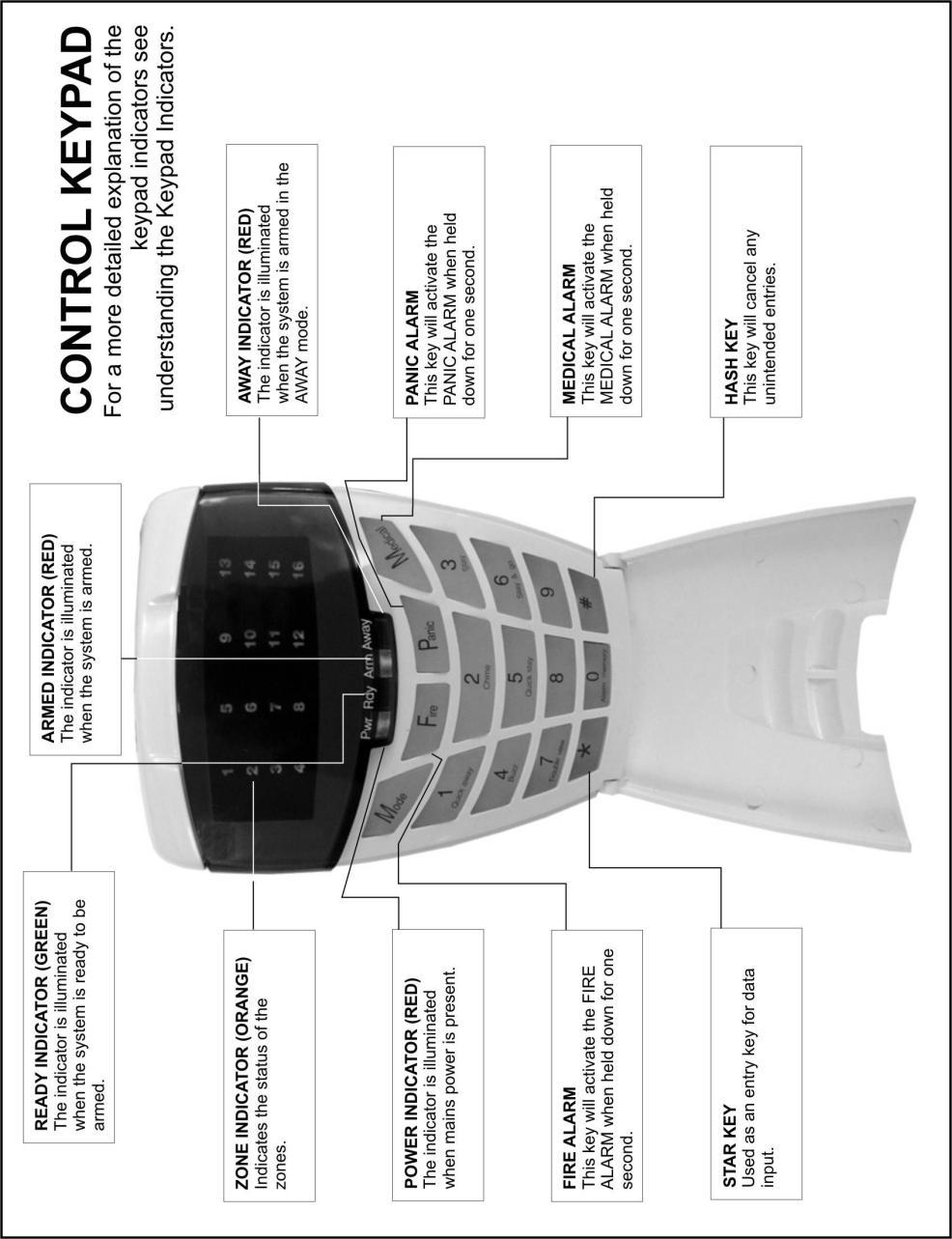
8 3. Understanding the Keypad Indicators Refer to the labelled pictures of the keypads. 1. ARMED Indicator (Red) On Off Flashing System Armed System Disarmed Alarm Condition (Check Alarm Memory zone details BEFORE re-arming) 2. AWAY Indicator (Red) On Off Flashing System Armed in Away Mode System Disarmed / Armed in Stay Mode User Programming (Chime/Buzz/Stay zones) 3. POWER Indicator (Red) On Flashing Mains Power is Present Trouble Condition 4. READY Indicator (Green) On System is Ready to be Armed 5. ZONE Indicators (Yellow) On Off Flashing Zone Bypassed Zone Clear Zone Violated or Tampered 8
9 4. The Keypad Buzzer [#] WITH any key from [0] to [3] for 1 second The keypad includes a buzzer which is used for audible signalling and verification of certain keypad functions. There are 4 possible volume settings: loud, medium, soft and click, loud being the default setting. To program the keypad volume, use the following table: Key Entry Keypad Buzzer Options [#] [3] Loud (Default setting) [#] [2] Medium [#] [1] Soft [#] [0] Click To change the volume (for this example to the soft setting) hold the [#] and [1] key down simultaneously for 1 second (long press). At the end of this delay, the keypad will respond with a beep at the new volume setting. This is a keypad specific setting, and applies to the keypad that this operation is performed on. All zones programmed as Chime or Buzz zones, will sound with a loud beep regardless of the keypad volume set above. 5. Setting the Time Hold down the [MODE] key until the beep, then enter [5] [*] [time] [*] 1. Hold down [MODE] until the keypad buzzer sounds. 2. Press [5] [*]. 3. Using the 24 hour clock format i.e. 17:15 enter the time. Only numerics need be entered however four digits must always be used e.g. for 01:45 press [0] [1] [4] [5]. 4. Press [*] to confirm your entry. 6. Programmable Functions Functions include: Quick Away Arm Quick Stay Arm Arm with Entry/Exit or Follower zones violated Stay Arm Stay Arm and Go Forced Arm Push to Arm Siren sound on Arm/Disarm (single toot arm / double toot disarm) Panic Alarm Fire Alarm Medical Alarm Chime zones 9
10 Buzz zones Zone tamper Arm with Key-switch or Remote Control 7. Arming the Control Panel 7.1 Away Arm [#] [USER CODE] (Leave via Entry/Exit zone) 1. Ensure that the READY indicator is on. If not check that all protected doors and windows are closed and that all movement has ceased in areas covered by motion detectors. If necessary, close the front door. 2. Press the [#] key. 3. Enter a valid [USER CODE]. If an incorrect code is entered the keypad buzzer will beep three times. In the event of an error press the [#] key and re-enter the code. 4. The ARMED indicator will come on and the keypad buzzer will beep repeatedly for the duration of the exit delay. Any bypassed zones will be indicated by a steady on zone indicator. 5. Leave only via a designated exit route (leaving by any other can set off the alarm.) The panel will arm at the end of the exit delay. 7.2 Quick Away Arm Hold down the [1] key until the beep If this function is enabled, it is possible to AWAY arm by simply holding down the [1] key until the keypad buzzer sounds and the arming process begins. NOTE: If the partition is already STAY armed this key will initialise AWAY arming. It is therefore possible to change directly from STAY armed to AWAY armed. 7.3 Stay Arm Stay arming allows the user to monitor selected perimeter zones and bypass interior zones. The user can remain on the premises with access to designated areas during the STAY ARM cycle. Any zone which may be violated accidentally should be programmed as a BUZZ ZONE. When violated, a BUZZ ZONE will cause the keypad buzzer to sound for thirty (30) seconds before sounding the siren. Entering a valid USER CODE before the siren sounds will silence the keypad buzzer and prevent the siren from sounding. To provide greater flexibility the panel caters for the programming of two different STAY PROFILES. Each STAY PROFILE contains a unique combination of STAY, BUZZ and ALARM zones which cater for a particular STAY ARM requirement. Example: PROFILE 1 might be used when the family goes to bed in the evening. In this profile some interior zones may be programmed as alarm zones or buzz zones, whereas PROFILE 2 is used while watching television when all interior zones would be bypassed. (See How to Select a Stay Profile, under Stay zones) 10
11 7.3.1 How to Stay Arm [#] [USER CODE] (Do not leave premises) 1. Select the required STAY PROFILE (See page 21) 2. Ensure that the READY indicator is on. If not, check that all protected doors and windows are closed and that all movement has ceased in the areas covered by motion detectors. 3. Press the [#] key. 4. Enter a valid [USER CODE]. If an incorrect code is entered the keypad will give an error beep. In the event of an error press the [#] key and re-enter the [USER CODE]. 5. The ARMED indicator will come on and the keypad buzzer will sound for the duration of the exit delay. 6. DO NOT violate the Entry/Exit zone (normally the front door). If the Entry/Exit zone is violated the system will arm in the AWAY mode. 7. Upon expiry of the exit delay, the AWAY indicator will remain off. 8. Any STAY zones will be automatically bypassed (indicated by a steadily lit indicator). 9. Ensure that you enter only those areas that are bypassed. 7.4 Quick Stay Arm Hold down the [5] key until the beep It is possible to STAY arm by holding down the [5] key until the keypad buzzer sounds. The panel will immediately arm into the stay mode without any exit delay. All stay zones will be bypassed. NOTE: Holding the button down again will cause the panel to toggle between stay profiles. This STAY profile then becomes the active profile and the panel will STAY arm using this profile - until you elect to switch profiles again How to Stay Arm and Go Hold down the [6] key until the beep This is a single key arm function which allows the user to STAY arm and leave the premises. If a partition is already stay armed, holding down the 6 key initiates an exit delay, thus allowing the user to leave the premises without disarming. At the end of the exit delay the partition will re-arm in the same stay profile it was armed in before the 6 key was held down. 1. Hold down the [6] key until the keypad buzzer sounds. The keypad buzzer will sound for the duration of the exit delay. Only leave via a designated exit route. 2. At the end of the exit delay the ARMED indicator will come on and the AWAY indicator will remain off. All stay zones will be bypassed. NOTE: Holding down the [6] key until the keypad buzzer sounds also ensures an Entry delay on entering the premises. 11
12 7.5 Key-switch or Remote Arming (If fitted) 1. Ensure that the READY indicator is lit before leaving. 2. Leave and close the door (remembering to lock!) 3. Activate the remote or the key-switch. The panel will arm in the away mode. (An IDS remote receiver with matching TX unit can be used to Stay Arm or Away Arm.) NOTE: If a remote control is used it is advisable to have the siren toot on arm function enabled. This provides verification that the system has armed. (Speak to your installer about this feature) 7.6 Auto Arm The panel may be programmed to arm automatically at a pre-programmed time. Should the premises be occupied at the time of auto arming, a valid [USER CODE] entered during the pre-arm delay will terminate the arming sequence. The pre-arm delay is signalled by an exit beep. 8. Disarming the Control Panel 8.1 How to Disarm with a User Code [#] [USER CODE] 1. Enter the premises through a designated entry route. Entering via any other route will cause an alarm. 2. As soon as the Entry/Exit zone is violated the entry delay will begin. The keypad buzzer will sound for the duration of the entry period. 3. Press the [#] key and enter a valid [USER CODE]. 4. Once the system disarms, the ARMED indicator will turn off and the keypad buzzer will stop sounding. 5. If no valid user code has been entered prior to the expiry of the entry delay period an alarm condition will be registered. 6. If the entry period is too short, have your installer change the entry delay period. NOTE: If a strobe (or flashing light) has been installed and an alarm condition is registered, the strobe will continue flashing after the siren has stopped sounding. Entering a valid [USER CODE] will cancel the strobe. 8.2 How to Disarm using a Key-switch or Remote 1. Activate the remote or key switch. 2. The system will disarm and the remote indicator (if installed) will turn off. If the siren toot on disarm option is enabled, the siren will provide a double toot when the panel is disarmed 12
13 9. Bypassing Zones The term BYPASS is used to describe a zone which has been deactivated; i.e. violation of a bypassed zone is ignored and will not cause an alarm condition. Once the system is armed it is not possible to bypass zones. All bypassed zones will be automatically cancelled each time the panel is disarmed and must be re-bypassed before the next arming. 9.1 Bypassing/Un-Bypassing a Zone Hold down [9] key until the beep, then enter [ZONE NUMBER] [*] [#] 1. Ensure that the panel is not armed (Armed LED OFF). 2. To enter bypass mode, hold down the [9] key for one second (until the keypad buzzer sounds). The Away LED will flash, and bypassed zones will be indicated by lit zone LED s. 3. Entering a zone number [ZONE NUMBER] [*] will toggle the corresponding LED. For example, [2] [*] will turn LED 2 on (if it was off) and off (if it was on). 4. Turn on the LED s corresponding to the zones you need to bypass. The LED zone indicators should now indicate only the zones that you require bypassing. 5. Once satisfied with your selection, press the [#] key to exit the bypass mode. NOTE: Panic zones cannot be bypassed and remember that all bypassed zones are reset at every panel disarm cycle. 10. Emergency Alarms 10.1 Fire Alarms Hold down the [F] key until the beep If the [F] key is pressed until the keypad beeps (approximately 1 second) a FIRE ALARM condition will be activated. The FIRE ALARM CONDITION may also be triggered by a smoke detector connected to an appropriately programmed zone. The siren will sound on and off repeatedly if programmed and the FIRE REPORTING CODE will be transmitted to the monitoring company. To silence the siren enter a valid [USER CODE] Panic Alarms Hold down the [P] key until the beep If the [P] key is pressed until the keypad beeps (approximately 1 second) a PANIC ALARM condition will be activated. A PANIC ALARM may also be activated using any FIXED PANIC button or a REMOTE PANIC button (if installed). 13
14 If the audible panic option has been selected, the siren will sound. A PANIC ALARM will be transmitted to the monitoring company. To silence the siren, enter a valid [USER CODE]. Press the [P] key only in an emergency situation which requires response by emergency personnel Medical Alarms Hold down the [M] key until the beep If the [M] key is pressed until the keypad beeps (approximately 1 second) a MEDICAL ALARM condition will be activated. The keypad buzzer will beep 5 times. A medical reporting code will be reported to the monitoring company Duress Alarms [#] [DURESS CODE] This is a special user code which should only be used in the unique situation where an intruder forces one to disarm the system under duress. When a [DURESS CODE] is entered, the control panel disarms. A Duress Alarm Code (if programmed) will be reported to the monitoring company. It is advisable to choose a Duress code which can be easily remembered by all family (or staff) members. 11. Alarm Memory Hold down the [0] key until the beep The Alarm Memory displays any zones which were violated, tampered with, or bypassed during the last arm cycle. A flashing ARMED indicator notifies the user of an alarm memory condition. To view the alarm memory, disarm the panel and continue as follows: (Hold down the [0] key for two seconds until the keypad buzzer sounds) 1. Hold down [0] until the keypad buzzer sounds. 2. The READY and POWER indicators will turn off and the keypad buzzer will sound briefly. 3. Lit zone indicators show which zones were violated during the last armed period. 4. Press 2 to display zones which were bypassed. 5. Press 3 to display which zones were tampered with. 6. Press 1 to return to violated zones. 7. Note that the alarm memory is erased at the beginning of each arm cycle so it should always be checked BEFORE re-arming, if necessary. 14
15 12. User Codes The IDS 1632 Alarm Panel has 250 programmable user codes. By default user code 1 is the Master USER CODE which contains a pre-programmed 4 digit code of NOTE: User codes may be 4 (default) or 6 digits long (with default code of ). This is a programmable feature Check with your installer to verify which option has been programmed Adding, Deleting and Editing User Codes The IDS 1632 Panel has a friendly programmable interface that allows you to add, modify or delete user codes. See Table 1 for a summary of programmable options. The programmable interface is accessed by entering the USER PROGRAMMING MODE. 13. How to Enter User Program Mode Hold down the [*] key until the beep, then enter [MASTER USER CODE] [*] [PROGRAMMABLE OPTION] [*] 1. Ensure that the panel is not armed. 2. Hold down the [*] key until the keypad buzzer sounds. 3. The ARMED and READY indicators will flash alternately. 4. Enter a [MASTER USER CODE]. The factory default is Should the [MASTER USER CODE] be defaulted to six digits, it will be Press the [*] key. A valid entry will be confirmed by a long beep. 5. If steps 1 to 4 are performed correctly, the READY indicator will flash. If an invalid code was entered the keypad buzzer will give an error beep. (3 short beeps). If the error beep occurs, press the [#] key (this clears all previous entries) and repeat steps 2 to Select a programmable option from Table 1. Example: To add a new user code, enter User Program Mode by completing steps 1 to 5 as listed above. To access Option 0, enter a value of [0] (See table 1) followed by [*]. Enter a [NEW USER CODE] followed by the [*] key. Once the user code is programmed enter the next code followed by [*]. To exit the program mode press the [#] key. For a full list of options refer to Table 1. Programming of these options is explained on the next page. 15
16 Table 1 : User Programming Options Options Option 0 Option 1 Option 2 Option 3 Option 4 Option 5 Option 8 Option 9 Option 10 Option 11 Option 12 Summary of Programmable Options Allows for the addition of new user codes. Allows editing of the user name displayed by LCD keypads. This option is only applicable if LCD keypads are installed. Allows editing of a selected user code. Note that the user code properties are not edited, only the user code itself. Allows viewing of the user code slot number for a selected code. There are 250 available user code slots. Allows editing of the user code properties for a selected user code. This is a bit mapped menu. Allows the allocation of a selected user code to designated partitions. This is a bitmapped menu. Adding User Remotes Deleting a USER CODE Allows the deletion of a user code using the user code slot number. Allows viewing of a user name if the slot number is known. Add user by slot number 14. Explanation of Programmable Options 14.1 Add a New User Code Option 0 Hold down the [*] key until the beep, then enter [MASTER CODE] [*] [0] [*] [New USER CODE] [*] 1. Enter the User Program Mode as per steps 1 to 4 on page Press the [0] key followed by the [*] key to select the programmable option 0 (zero). The Ready and Armed indicators will flash simultaneously. 3. Enter the [New USER CODE] followed by the [*] key. 4. Further codes may be added by repeating step 3 above. 5. After entering the last code press the [#] key to exit the user program mode Edit a User Name Option 1 (LCD Keypads only) Hold down the [*] key until the beep, then enter [MASTER CODE] [*] [1] [*] [User Name] [*] 1. Enter the User Program Mode as per steps 1 to 4 on page Press the [1] key followed by the [*] key to select programmable option The Armed indicator will flash. 3. Enter the [USER CODE] of the User whose name you wish to edit. 4. User Names are displayed as the User Slot Number by default. Edit the User Number so that it reads the correct User Name. To confirm the entry press [*]. 5. Repeat steps 3 to 4 until you have edited all the names you require and then press [#] to exit. 16
17 NOTE: Cursor control keys The [P] key can be used to move the cursor towards the right, whilst the [F] key can be used to move from the curser towards the left. The [MODE] key toggles between upper and lower case (underscore curser for lower case, block curser for upper case) Edit a Selected User Code Option 2 Hold down the [*] key until the beep, then enter [MASTER CODE] [*] [2] [*] [Old Code] [*] [New Code] [*] 1. Enter the User Program Mode as per steps 1 to 4 on page Press the [2] key followed by the [*] key to select programmable option 2. The READY and Armed indicators will flash simultaneously. 3. Enter the [USER CODE] which is to be edited followed by the [*] key. 4. The READY indicator will flash and the AWAY indicator will be on. 5. Enter the [NEW CODE] followed by the [*] key. 6. The READY and ARMED indicators will flash simultaneously. 7. To edit other codes repeat steps 3 to Press the [#] key to exit the User Program Mode View a User Code Slot Number Option 3 Hold down the [*] key until the beep, then enter [MASTER CODE] [*] [3] [*] [USER CODE] [*] 1. Enter the User Program Mode as per steps 1 to 4 on page Press the [3] key followed by the [*] key to select programmable option 3. The READY and ARMED indicators will flash simultaneously. 3. Enter the [USER CODE] followed by the [*] key. 4. The READY indicator will flash and the AWAY indicator will be on. 5. The [USER CODE] slot number will be displayed by the Zone indicators. (See table 2) 6. Press the [#] key to exit the User Program Mode User Code Properties Option 4 Hold down the [*] key until the beep, then enter [MASTER CODE] [*] [4] [*] [USER CODE] [*] [PROPERTY No.] [*] 1. Enter the User Program Mode as per steps 1 to 4 on page Press the [4] key followed by the [*] key to select programmable option 4. The READY and ARMED indicators will flash simultaneously. 3. Enter the [USER CODE] followed by the [*] key. 4. The READY indicator will flash and the AWAY indicator will be on. 5. The properties assigned to the USER CODE are displayed by the Zone indicators. Lit LED(s) indicate that certain properties have been assigned to the USER CODE. Refer to Table 2 for a list of USER CODE properties. 6. To select a user code property, press the key which corresponds to that property followed by the [*] key. The appropriate zone LED will come on. To deselect a property, press the corresponding key followed by the [*] key and the LED will be off. 17
18 Example: To enable a USER CODE to function as a duress code press the [2] key followed by the [*] key. The zone 2 LED will come on to confirm the selection. 7. Repeat step 6 until the desired properties have been programmed. 8. Press the [#] key to exit the User Program Mode. NOTE: Property #1 (Master User settings) are set during installation and cannot be changed by any User (even the Master User) Explanation of User Code Properties Table 2 : User Code Properties Zone LED Property 1 Master User 2 Duress Code 3 Arm to Disarm Code [Maid s Code] 4 Group Arm 5 Group Disarm 6 Arm Code 7 Disarm Code 8 Report User Open Close 9 User Phone in Access 10 Report User Access Master User (Only Adjustable by the Installer) When assigned to a USER CODE, this property affords this user Master User status, which means they will be able to edit USER CODES. This is NOT a user-adjustable setting, only Alarm Installers have access to alter the Master User Status. By default the first User is a Master User. If more Master Users are needed, call your Installer Duress Code This property causes this USER CODE, when entered, to disarm the panel normally - however a DURESS REPORTING CODE is transmitted to the monitoring company to inform them that you have been forced to disarm the control panel by an intruder. It is advisable to choose a code that can be easily remembered by all family (or staff) members Maid s Code Codes having this property may be used to limit access to the premises. The MAID S CODE will only disarm the system if the same code was used for arming. If armed with a code other than this code, the system will view an attempt to disarm using the MAID S CODE as an invalid entry. Any valid user code will disarm the system if it has been armed with the MAID S CODE. 18
19 Group Arm Code This code when entered will arm the partitions assigned to the user depending on their status. If all partitions are disarmed, entering a group code will arm all of the assigned partitions. In a case where some partitions are armed and others disarmed, entering this group code at the keypad of the disarmed partition will arm the disarmed partitions only Group Disarm Code This code when entered will disarm the partitions assigned to the user depending on their status. If all partitions are armed, entering a group code will disarm all of the assigned partitions. In the case where some partitions are disarmed and others armed, entering this group code at the keypad of the armed partition will disarm the armed partitions only Arm Code Codes having this property, when entered, will arm the partition as long as this code is associated with this the current partition Disarm Code Codes having this property, when entered, will disarm the partition as long as this code is associated with this the current partition Report Open and Close This option enables reporting of a pre-programmed reporting code when a partition assigned to this user is armed/disarmed User Phone in Access If enabled this allows the user to arm or disarm the panel using a DTMF telephone Report User Access Codes with this property enabled will cause the Alarm Panel to send a User Access Report Code to the Security Company every time these users enter their code. 19
20 14.6 Assign User Code to Partitions Option 5 Hold down the [*] key until the beep, then enter [MASTER CODE] [*] [5] [*] [USER CODE] [*] [ZONE LED No] [*] [#] 1. Enter the User Program Mode as per steps 1 to 4 on page Press the [5] key followed by the [*] key to select programmable option The READY and ARMED LED s will flash simultaneously. 3. Enter the [USER CODE] followed by the [*] key. 4. The READY indicator will flash and the AWAY indicator will be lit. 5. The partitions to which the USER CODE is assigned are displayed by the zone LED s. If zone LED 1 is on the USER CODE can arm or disarm partition 1. If zone LED 2 is on, the USER CODE can arm or disarm partition 2. If zone LED s 1 and 2 are both lit, the USER CODE can arm and disarm BOTH partitions 1 and 2. It is possible to program codes to arm/disarm a selection from any of the eight possible partitions in the IDS To select which partitions the USER CODE may arm or disarm, toggle zone LED s by entering the [ZONE LED NUMBER] followed by the [*] key. 7. Repeat step 6 until the USER CODE has been assigned to the correct partition(s). 8. Press the [#] key to exit User Program Mode Adding User Remotes Option 8 Hold down the [*] key until the beep, then enter [MASTER CODE] [*] [8] [*] [USER CODE] [*] <press remote button> [*] [#] 1. Enter the User Program Mode as per steps 1 to 4 on page Press the [8] key followed by the [*] key to select programmable option The READY and ARMED LED s will flash simultaneously. 3. Enter the [USER CODE] followed by the [*] key. 4. The READY indicator will flash and the AWAY indicator will be lit. 5. Press any button on the new remote. This will assign the new remote to the user code as entered in Step Press [*] 7. To add additional remotes, repeat steps Press the [#] key to exit User Program Mode Delete User Code Option 9 (Code known) Hold down the [*] key until the beep, then enter [MASTER CODE] [*] [9] [*] [USER CODE] [*] [#] 1. Enter the User Program Mode as per steps 1 to 4 on page Press the [9] key followed by the [*] key to select Menu option 9. The READY and ARMED indicators will flash simultaneously. 3. Enter the [USER CODE] to be deleted followed by the [*] key. Deleting the code in slot one will reprogram it to Further codes may be deleted by repeating Step 3 above. 5. After deleting the final code press the [#] key to exit User Program Mode. 20
21 14.9 Delete a User Code Option 10 ( Slot known) Hold down the [*] key until the beep, then enter [MASTER CODE] [*] [10] [*] [SLOT NUMBER] [*] [#] 1. Enter the User Program Mode as per steps 1 to 4 on page Press the [1] key then the [0] key followed by the [*] key. The ARMED and READY indicators will flash simultaneously. 3. Enter the [SLOT NUMBER] for the USER CODE you wish to delete followed by the [*] key. You can determine the slot number of a particular code by using programmable option Further USER CODEs may be deleted by repeating Step After deleting the final code, press the [#] key to exit Viewing a User Name Option 11 (Slot Known) (LCD Keypad only) Hold down the [*] key until the beep, then enter [MASTER CODE] [*] [1] [1] [*] [SLOT NUMBER] [*] [#] 1. Enter the User Program Mode as per steps 1 to 4 on page Press the [1] key then the [1] key again followed by the [*] key. 3. Enter the [SLOT NUMBER] followed by the [*] key. 4. The USER NAME will be displayed. Default names are displayed as the SLOT NUMBER (i.e. If the SLOT NUMBER has not been edited as per Option 1) 5. Press [#] to exit User Program Mode. 15. Stay Zones Stay arming allows the user to monitor selected perimeter zones and bypass interior zones. The user can remain on the premises with access to designated areas during the STAY ARM cycle. Any zone which may be violated accidentally should be programmed as a buzz zone. When violated a buzz zone will cause the keypad buzzer to sound for thirty (30) seconds before sounding the siren. Entering a valid User Code before the siren sounds will silence the keypad buzzer and prevent the siren from sounding. To provide greater flexibility the panel caters for the programming of two (2) different STAY PROFILES. Each STAY PROFILE contains a unique combination of STAY, BUZZ and ALARM zones which cater for a particular STAY ARM requirement. If a partition is stay armed using Profile one, it is possible to toggle the panel arm status directly to stay arm profile 2 by holding the [5] key for two seconds. STAY and BUZZ zones can be programmed for each profile once the profile has been selected (below) How to Select a Stay Profile Hold down the [MODE] key until the beep, then enter [2] [*] [PROFILE NUMBER] [*] 1. Ensure that the Panel is disarmed. 2. Press the [#] key to clear any previous entries. 3. Hold [MODE] down for one second until the keypad beeps. 21
22 4. Press the [2] key followed by the [*] key. 5. Press [1] or [2] for the required profile. 6. Press [*] to enter. The buzzer will give a long beep. 7. Program STAY and BUZZ zones for the profile (See pages 28 and 29) or ARM the profile 15.2 How to Program Stay Zones After selecting the required stay profile (Page 27), Hold down the [3] key until the beep, then enter [ZONE NUMBER] [*] [#] 1. Select the required stay profile (See Page 21) 2. Hold down the [3] key until the keypad buzzer sounds. The AWAY indicator will flash indicating that the panel is in the Stay zone programming mode. 3. Entering a [ZONE NUMBER] will toggle the corresponding LED. For example, [2] [*] will turn LED 2 on (if it was off) and off (if it was on). (*Flashing zone LED s indicate zones that have been set as Buzz zones and therefore cannot be changed in this menu) 4. Turn on the LED s corresponding to the zones you need to be Stay zones. The LED zone indicators should now indicate only the zones that you require to be Stay zones. 5. Once satisfied with your selection, press the [#] key to exit the Stay zone mode. NOTE: Panic zones cannot be selected as Stay zones. *Buzz zones cannot be selected as Stay zones. The Buzz status must be cleared first. 16. Buzz Zones Violation of a buzz zone when Stay Armed will cause the keypad buzzer to sound for a period of 30 seconds during which time a valid user code must be entered. If a valid user code is not entered during this period the system will register an alarm condition. This feature helps prevent unnecessary false alarms. NOTE: If an Entry/Exit zone is programmed as a buzz zone, violation of the Entry/Exit zone (when the panel is Stay Armed) will cause the keypad buzzer to sound for the duration of the entry delay time (in place of the default 30 seconds). This, if the panel is stay armed, allows the user to enter the premises and disarm the panel. If it is not programmed as a Buzz zone, the alarm will be triggered immediately. If the panel was armed using the [6] key (Stay Arm and Go) violation of the Entry/Exit zone will always start the Entry/Exit delay How to Program a Buzz Zone After selecting the required stay profile (Page 21), Hold down the [4] key until the beep, then enter [ZONE NUMBER] [*] [#] 1. Select the required stay profile (See Page 21) 2. Hold down the [4] key until the keypad buzzer sounds. The AWAY indicator will flash indicating that the panel is in the Buzz zone programming mode. 22
23 3. Entering a [ZONE NUMBER] will toggle the corresponding LED. For example, [2] [*] will turn LED 2 on (if it was off) and off (if it was on). (*Flashing zone LED s indicate zones that have been set as Stay zones and therefore cannot be changed in this menu) 4. Turn on the LED s corresponding to the zones you need to be Buzz zones. The LED zone indicators should now indicate only the zones that you require to be Buzz zones. 5. Once satisfied with your selection, press the [#] key to exit the Buzz zone mode. NOTE: Panic zones cannot be set as Buzz zones 17. Chime Zones The chime mode allows the user to monitor nominated zones while the system is disarmed. The keypad buzzer will sound five times when the nominated zone is violated - the siren will NOT sound and no alarm condition will be reported. Example: If you wish to know each time someone enters or exits the front door of your office program this zone as a chime zone, the keypad will beep each time someone opens the front door How to Program Chime Zones Hold down the [2] key until the beep, then enter [ZONE NUMBER] [*] [#] 1. Select the required stay profile (See Page 21) 2. Hold down the [2] key until the keypad buzzer sounds. The AWAY indicator will flash indicating that the panel is in the Chime zone programming mode. 3. Entering a zone number will toggle the corresponding LED. For example, [2] [*] will turn LED 2 on (if it was off) and off (if it was on). 4. Turn on the LED s corresponding to the zones you need to be CHIME zones. The LED zone indicators should now indicate only the zones that you require to be CHIME zones. 5. Once satisfied with your selection, press the [#] key to exit the CHIME zone mode. 18. Viewing Trouble Conditions Hold down the [7] key until the beep The user is alerted to a trouble condition via a flashing power LED. It is also possible to enable a trouble beep. (Ask your Alarm Panel Installer) If the trouble beep has been enabled, the keypad buzzer will sound to alert the user that a trouble condition has occurred. Press the [#] key to silence the buzzer. Hold down the [7] key for two seconds. The ARMED, AWAY and READY indicators will be flashing simultaneously showing that the keypad is in the TROUBLE VIEW MODE. Refer to the Table 3 to find the significance of each lit zone LED. The system will automatically exit the TROUBLE VIEWING MODE after one minute. (Alternately to exit this mode press [#]). NOTE: Certain trouble conditions will only clear once the trouble condition has restored. To cancel the beeping without viewing the trouble conditions, press [#] key. 23
24 Table 3 : Trouble Conditions Indicator Trouble Condition 1 AC Mains Failure 2 Failure to communicate successfully to monitoring company 3 Phone line trouble 4 Siren tamper 5 Low battery 6 Loss of Clock Timer 7 Engineer Reset 8 Box tamper 9 n/a 10 Tamper on peripheral device 11 Communication loss to peripheral device 12 Loss of power to peripheral devices 13 Reserved 14 SIM PIN Trouble 15 Low Airtime 19. Changing a Partition Hold down the [MODE] key until the beep, then enter [1] [*] [Partition Number] [*] To change partitions the keypad must be a global keypad. 1. Ensure that the Panel is disarmed 2. Hold [MODE] until the keypad beeps. 3. Press [1] [*] followed by the [Partition Number] [*]. If no key is pressed on the keypad for specified delay period (default is 20 seconds), the keypad will beep and default back to its original partition. The keypads may be programmed to remain in the new partition. (Ask your Installer about this option). Entering partition numbers other than those in the range 1 to 8 will produce a key entry error. 20. Output Control via a Keypad If the panel has been set up to control switching functions via its outputs, these can be controlled via the keypad - e.g. turning lights on and off. Hold down the [MODE] key and press [3] [*]. (Any outputs that are currently set [ON] will be shown as an on zone indicator.) To toggle the output status, enter [OUTPUT NUMBER] followed by [*]. Press [#] to exit User Program Mode. Ensure that you have checked with your installer which outputs are used for radio reporting so as to prevent the triggering of false alarms. 24
25 21. Remote Telephone Access Please note that this section only applies if programmed by your installer. The IDS 1632 Alarm Panel has a secure, remote telephone interface that allows a user to arm/disarm, to bypass/un-bypass zones and to set programmable outputs via a phone line. A user accesses the remote dial-in interface by dialling the Alarm Panel using a DTMF phone. To access the remote dial-in interface, dial the Alarm Panel and wait the number of rings programmed (the default number of rings being15). If the fax defeat function has been enabled, dial the panel and hang up after one ring. Dial in again within 1 minute, the panel will pickup immediately and transmit handshake tones consisting of a high pitch tone for two seconds followed by a lower pitch tone for one second. Within twenty seconds of the panel transmitting the handshake tones, enter a valid user code on the DTMF enabled phone. If a user code is not entered or if the user code is invalid - the panel will release the line. If the user code is valid and telephone access has been enabled, the panel will give a single confirmation beep indicating that the user has gained access to the remote interface. If no keypresses are detected for twenty seconds once access has been gained to the remote interface the panel will release the line. Should the panel be programmed to report to your cellular telephone, entering the user code in the delay between beeps will also allow access to the remote telephone interface. The addition of a Voice Module to your Alarm Panel will provide a voice prompted menu as well as voiced reporting over the telephone. (Provided your panel connects to phone lines, or has GPRS Module fitted) 25
26 Table 4 : Remote Telephone Operation Single Partition Installation Key Key Press Sequence Action 1 [1] [*] Arm 2 [2] [*] Disarm 3 [3] [Zone Number] [*] Bypasses the zone number entered 4 [4] [Zone Number] [*] Un-Bypass the zone number entered Currently violated zones No of beeps = zone that was violated 5 [5] [*] Pressing [5] [*] again will move to the next violated zone Zones violated during last arm cycle No of beeps = zone that was violated 6 [6] [*] Pressing [5] [*] again will move to the next violated zone 7 [6] [Output Number] [*] Will turn an output on 8 [8] [Output Number] [*] Will turn an output off 9 [9] [Output Number] [*] Reports output status One beep = output on Two beeps = output off 0 [0] [Door Number] [*] Opens the specified Door # [#] [*] Ends the call Multi-Partition Installation Key Key Press Sequence Action 1 [Partition No] [1] [*] Arm 2 [Partition No] [2] [*] Disarm 3 [3] [Zone Number] [*] Bypasses the zone number entered 4 [4] [Zone Number] [*] Un-Bypass the zone number entered Currently violated zones No of beeps = zone that was violated 5 [5] [*] Pressing [5] [*] again will move to the next violated zone Zones violated during last arm cycle No of beeps = zone that was violated 6 [6] [*] Pressing [5] [*] again will move to the next violated zone 7 [6] [Output Number] [*] Will turn an output on 8 [8] [Output Number] [*] Will turn an output off 9 [9] [Output Number] [*] Reports output status One beep = output on Two beeps = output off 0 [0] [Door Number] [*] Opens the specified Door # [#] [*] Ends the call 26
27 22. Controlling the IDS 1632 via Cellphone SMS This functionality is only available when an IDS GPRS module is installed with the IDS 1632 Alarm Panel. You can control your 1632 Alarm Panel on your premises from any part of the world with coverage that supports your cellphone. Each command you send must include the word code (without the quotes), followed by the user code and then the required instruction. Spaces are ignored so they can be included or left out - and the module is not case sensitive, so upper-case, lower-case (or a mixture of the two) are all acceptable. More than one command can be included in the same SMS. If a command is to be applied to more than one entity, for example to bypass zones 2 and 5, the numbers can be listed with a + symbol between them, like so:- code 1234 bypass 2+5 The following table lists the commands are supported: Table 5 : SMS Commands Command In place of x include: Panel response Arm x The number(s) of the partition(s) to arm. Arm x accepted/rejected. Disarm x The number(s) of the partition(s) to disarm. Disarm x accepted/rejected. Bypass x The zone(s) to bypass. Bypass x accepted/rejected. Un-bypass x The zone(s) to un-bypass. Un-bypass x accepted/rejected. output x on The output(s) to activate. Output x on. output x off The output(s) to deactivate. Output x off. zones N/A Violated zones bypass? N/A Bypassed zones output? Outputs to query the status of. Status of listed outputs. Arm? x Optional - partitions to query status of. Status of listed partitions. If none are listed, status of all partitions. Reply x Another cell phone number to also Panel sends response to this receive the panel response. number too The panel responses will be sent to the originating cell phone, to the number programmed as SMS user number 1 (if they are different), and to the response number (if specified). 27
IDS816 User Manual H Issued January 2009
 1 Contents Glossary-------------------------------------------------------------------------------------------------------------------6 1. Introduction to the IDS 816---------------------------------------------------------------------------7
IDS S E C U R I T Y IDS816. User Manual MANUAL NO C ISSUED APRIL 2005 VERSION 2.00
 INHEP DIGITAL IDS S E C U R I T Y IDS816 User Manual MANUAL NO. 700-283-01C ISSUED APRIL 2005 VERSION 2.00 Contents 1. Introduction to the IDS816... 4 2. Understanding the Keypad Indicators... 4 3. Programmable
IDS S E C U R I T Y IDS816. User Manual MANUAL NO B ISSUED DEC 2004 VERSION 2.00
 INHEP DIGITAL IDS S E C U R I T Y IDS816 User Manual MANUAL NO. 700-283-01 B ISSUED DEC 2004 VERSION 2.00 Contents 1. Introduction to the IDS816... 4 2. Understanding the Keypad Indicators... 4 3. Programmable
IDS S E C U R I T Y IDS816. User Manual. MANUAL NO A ISSUED November 2004 VERSION 1.00
 INHEP DIGITAL IDS S E C U R I T Y IDS816 User Manual MANUAL NO. 700-283-02A ISSUED November 2004 VERSION 1.00 Contents 1. Introduction to the IDS816... 4 2. Understanding the Keypad Indicators... 4 3.
Watchguard WGAP864 User Manual
 Watchguard WGAP864 User Manual v1.0 Issued September 2016 1 2 Table of Contents Glossary... 5 1. Introduction to your Watchguard WGAP864... 6 2. Before Operating your Alarm System... 6 3. Understanding
Contents. Glossary Introduction to the IDS Notes Understanding the Keypad Indicators Operation of the Keypad...
 2 Contents Glossary...7 1. Introduction to the IDS805...8 1.1 Notes...8 2. Understanding the Keypad Indicators...8 3. Operation of the Keypad...9 4. System Information...10 4.1 Programmed Functions...10
IDS800 USER MANUAL. Summary of Operation. + [ ] 2 IDS800 USER MANUAL NO K ISSUED APR 2003 VER 1.44
![IDS800 USER MANUAL. Summary of Operation. + [ ] 2 IDS800 USER MANUAL NO K ISSUED APR 2003 VER 1.44](/thumbs/89/98095999.jpg "IDS800 USER MANUAL. Summary of Operation. + [ ] 2 IDS800 USER MANUAL NO K ISSUED APR 2003 VER 1.44") Summary of Operation A rm/ disarm [#] + [USER CODE] Quick Quick Quick Away Arm Stay Arm Stay Arm & Go H old down [ 1] for 1 second H old down [ 5] for 1 second H old down [ 6] for 1 second Panic Fire Medical
Summary of Operation A rm/ disarm [#] + [USER CODE] Quick Quick Quick Away Arm Stay Arm Stay Arm & Go H old down [ 1] for 1 second H old down [ 5] for 1 second H old down [ 6] for 1 second Panic Fire Medical
L900 series USER MANUAL
 INTRODUCTION The BLUGUARD Control Panel is designed for simple operation yet provides the maximum protection for you. Please read this manual carefully and follow the instructions contained in this book.
Elite 16D Version 16 Zone Controller Arrowhead Alarm Products Ltd. Operating Guide. Proudly Designed and Manufactured in New Zealand
 6 Elite 16D Version 16 Zone Controller Arrowhead Alarm Products Ltd Operating Guide 1 Proudly Designed and Manufactured in New Zealand CONTENTS Page No. INTRODUCTION 3 About your Alarm 3 OPERATING YOUR
Destiny Destiny Owners Manual
 Destiny 4100 Destiny 4100 Owners Manual TABLE OF CONTENTS INTRODUCTION Control Panel...3 Detection Devices...3 Telephone Keypads...3 GLOSSARY... 4-5 LOCAL PHONE ACCESS Using Your Telephones As Keypads...6
Elite 64 Version 64 Zone Controller Arrowhead Alarm Products Ltd. Operating Guide. Proudly Designed and Manufactured in New Zealand
 2 Elite 64 Version 64 Zone Controller Arrowhead Alarm Products Ltd Operating Guide Proudly Designed and Manufactured in New Zealand 1 CONTENTS Page No. INTRODUCTION 3 About your Alarm 3 OPERATING YOUR
AXI LED USER MANUAL (REV. 1.0)
") Security & Home Automation System AXI LED USER MANUAL (REV. 1.0) CONTENTS PREFACE FEATURES LED KEYPAD OUTLOOK 1.0 LIGHT INDICATION 1 2 4 6 CHAPTER 1: ALARM SYSTEM CONTROL 1.0 USING LED KEYPAD 1.0.1 ARMING
Security & Home Automation System AXI LED USER MANUAL (REV. 1.0) CONTENTS PREFACE FEATURES LED KEYPAD OUTLOOK 1.0 LIGHT INDICATION 1 2 4 6 CHAPTER 1: ALARM SYSTEM CONTROL 1.0 USING LED KEYPAD 1.0.1 ARMING
Digiplex LED Keypads User s Manual
 KLEDEU03.fm Page -1 Friday, May 4, 2001 11:25 AM Digiplex LED Keypads User s Manual KLEDEU03.fm Page 0 Friday, May 4, 2001 11:25 AM KLEDEU03.fm Page 1 Friday, May 4, 2001 11:25 AM TABLE OF CONTENTS 1.0
Security System. User Guide for the LED Command Center
 Security System User Guide for the LED Command Center National Security Systems Inc (800)457-1999 MY SECURITY COMPANY IS: CALL BEFORE TEST: THIS SECURITY SYSTEM IS CONNECTED TO TELEPHONE NUMBER: THE SECURITY
User s Guide. SUB-MA7240O-0001.OG.Solution doc. Created: 6/05/03. Last Updated: 23/09/03. MA7240AO-0001 Version 1.0
 User s Guide SUB-MA7240O-0001.OG.Solution40-111.doc Created: 6/05/03 Last Updated: 23/09/03 MA7240AO-0001 Version 1.0 2 Table Of Contents User List...6 Quick Reference..7 Features...7 Keypad User's Guide...8
NetworX NX-8V2. LED Keypad User Manual
 NetworX NX-8V2 LED Keypad User Manual POWER Light is on when AC power is present; flashes to indicate a low battery condition. ARMED Light is on when armed; off when disarmed; flashes to indicate a previous
NX-148 LCD CODE PAD TABLE OF CONTENTS
 NX-148 LCD CODE PAD TABLE OF CONTENTS Glossary Of Terms... 4 Understanding The Lights... 5 Code Pad Functions Arming In The ON Mode... 6 Making The System Ready To Arm... 7 Using Quick Arm... 7 Arming
Control/Communicator Installation Manual
 DAS NETWORX NX-12 Control/Communicator Installation Manual General Description...2 Ordering Information...2 Option Definitions...3 Programming the LED Code Pads...5 Programming the NX-12...9 Types of Programming
Alarm Control Panel WIC-16Z4P WIC-5Z2P. User Instructions
 WIC-16Z4P WIC-5Z2P User Instructions Page : 2/14 INDEX # Function Page 1 Add a New User Code 11 2 Arm or Disarm All Areas or Disarm Selected Areas (Partitioned System) 8 3 Arming the System (Away Mode)
Solution Ultima 862 Operators Manual ISSUE 1.10
 Solution Ultima 862 Operators Manual ISSUE 1.10 Solution Ultima 862 Operators Manual Copyright 2001 by, SYDNEY, AUSTRALIA Document Part Number MA486O DOCUMENT ISSUE 1.10 Printed 24 April 2001 This documentation
DESTINY OWNER S MANUAL
 DESTINY OWNER S MANUAL DESTINY You have made a wise decision to protect your family and property with the DESTINY Security System. The DESTINY has been designed to provide you with a maximum level of security
User s Information Guide R2A
 Pi HSC505 Home Security Controller User s Information Guide R2A Page 1 of 15 of its development program. 1This document and product are copyrighted and all rights are reserved. Introduction Convention
HILLS Series LED Code Pad User Manual
 HILLS Series LED Code Pad User Manual Not all features may be available on your system Check with your installer to find out which features are programmed Page 2 TABLE OF CONTENTS Code Pad Diagrams...2
NetworX Series. NX-8 Commercial Fire Panel Installation and Startup
 NetworX Series NX-8 Commercial Fire Panel Installation and Startup 2004 GE Security All rights reserved. Printed in the United States of America. These instructions do not purport to cover all details
DESTINY 6100 SERIES SECURITY SYSTEM OWNER S MANUAL V1 12/01
 DESTINY 6100 SERIES SECURITY SYSTEM OWNER S MANUAL 800-6006V1 12/01 System Overview General Information Control Panel Detection Devices You have made a wise decision to protect your family and property
Understanding the Code Pad lights...4. Code Pad tones...5. Fully arming the system On MODE...6. Fully arming the system - Quick Arm MODE...
 TABLE OF CONTENTS...Glossary of terms...2...code Pad Diagram...3 Understanding the Code Pad lights...4 Code Pad tones...5 Fully arming the system On MODE...6 Fully arming the system - Quick Arm MODE...6
Power Wave LCD Keypads. Users Operating and Programming Guide Version 2.00
 Power Wave LCD Keypads CR-16S CR-16M Users Operating and Programming Guide Version 2.00 P/N 7102265 Rev. C N.A May 2003 Contents Introduction...4 Meet the PowerWave Alarm Control System... 4 Typical Alarm
Voice Board. Installation and Programming Guide. Runner 4/8,PowerWave 4/8/16 &, Elite64. Add-on Board For Storing Recorded Voice Messages
 ELECTRONIC ENGINEERING LTD. Voice Board Runner 4/8,PowerWave 4/8/16 &, Elite64 Add-on Board For Storing Recorded Voice Messages And listen-in. Installation and Programming Guide. P/N 7101372 Rev. C V.K
Using Your. Security System With LED Keypad S5030, S5031, S5032
 Using Your Security System With LED Keypad S5030, S5031, S5032 Contents 1 Overview Your Security System... 1 How Your Security System Works... 2 Your System's Programming... 3 Getting Used to Your System...
Solution Ultima Series Operators Manual ISSUE 1.00
 Solution Ultima Series Operators Manual ISSUE 1.00 Solution Ultima Series Operators Manual Copyright 1998 by, SYDNEY, AUSTRALIA Document Part Number MA488O DOCUMENT ISSUE 1.00 Printed 16 February 1999
NETWORX TM. User manual NX-4
 NETWORX TM User manual NX-4 POWER Light is on when AC power is present; flashes to indicate a low battery condition. ARMED Light is on when armed; off when disarmed; flashes to indicate a previous alarm.
Table of Contents. Appendix A Special Characters 31
 Table of Contents Introduction 2 Section 1: General System Operation 3 1.1 Getting to Know Your System... 3 1.2 How to Arm... 4 1.3 Alternate Arming Methods... 5 1.4 Disarming... 6 1.5 Alarm Memory...
SECURITY SYSTEM NOTES SPECIAL CODES ENTRY / EXIT DELAY TIMES ARM / DISARM CODES ZONE DESCRIPTIONS
 SECURITY SYSTEM NOTES Installing/Service Company For Service Call SPECIAL CODES "Chime" Digit 1 "Partial Arm" Digit 2 "Quick Arm" Digit 3 ENTRY / EXIT DELAY TIMES Exit Delay Time Entry Delay Time Secondary
Content. 1. Introduction to the IDS Features Installation and Wiring End-of-Line Resistors/Tamper per Zone...
 1 2 Content 1. Introduction to the IDS 805... 7 1.1 Features...7 2. Installation and Wiring...8 3. End-of-Line Resistors/Tamper per Zone...9 4. Connecting the Telephone Communicator...10 5. Programmable
PowerWave-16. Users Operating and Programming Guide Version P/N Rev. B N.A July 2002
 ELECTRONIC ENGINEERING LTD. PowerWave-16 16 zone Control panel Communicator Users Operating and Programming Guide Version 6.20 P/N 7121240 Rev. B N.A July 2002 Contents Introduction...4 Meet the Crow Alarm
ABORT Light flashes during an abort delay time; is on during or after an alarm report to the central station. EMERGENCY ACTIVATION KEYS
 POWER Light is on when AC power is present; flashes to indicate a low battery condition. CHIME Light is on when the chime feature is active. ABORT Light flashes during an abort delay time; is on during
Security System. User s Guide for the Text Command Center
 User s Guide for the Text Command Center MY ALARM COMPANY IS: CALL BEFORE TEST: THIS SECURITY SYSTEM IS CONNECTED TO TELEPHONE NUMBER: THE SECURITY CONTROL PANEL IS CONNECTED TO THE PHONE JACK LOCATED:
NetworX Series NX-1500E LED Keypad
 NetworX Series NX-1500E LED Keypad User Manual SECURITY SYSTEM NOTES Installing/Service Company For Service Call Central Station Duress Code FUNCTION CODES Function Code Controls Function This system
Solution 880 Operators Manual. Issue 1.00
 Solution 880 Operators Manual Issue 1.00 Solution 880 Operators Manual Copyright 1998 by, SYDNEY, AUSTRALIA Document Part Number MA408O Document ISSUE 1.00 Printed 15 June 1998 This documentation is provided
Version 1.03 January-2002 USER S MANUAL
 Version 1.03 January-2002 1 USER S MANUAL 2 Version 1.03 January-2002 System Details CUSTOMER:...... PHONE:... FAX:... INSTALLED BY:...... PHONE:... FAX:... MAINTENANCE & SERVICE:...... PHONE:... FAX:...
PROGRAMMING PROCEDURES (Table 3)
") CONDOPLEX 2600/2600A/2700 Suite Panel User Manual Document Version 8.4 Oct 19, 1998 Condoplex 1998 PROGRAMMING PROCEDURES (Table 3) FUNCTION PRESS KEYPAD DISPLAY Delete user code or duress code. 0 (hold)
CONDOPLEX 2600/2600A/2700 Suite Panel User Manual Document Version 8.4 Oct 19, 1998 Condoplex 1998 PROGRAMMING PROCEDURES (Table 3) FUNCTION PRESS KEYPAD DISPLAY Delete user code or duress code. 0 (hold)
SECURITY SYSTEM NOTES
 SECURITY SYSTEM NOTES Installing/Service Company For Service Call Central Station Duress Code FUNCTION CODES Function Code Controls Function EMERGENCY ACTIVATION KEYS (check if enabled) Fire Auxiliary
Solution 844 Operators Manual ISSUE 1.10
 Solution 844 Operators Manual ISSUE 1.10 Solution 844 Operators Manual Copyright 2001 by, SYDNEY, AUSTRALIA Document Part Number MA406O DOCUMENT ISSUE 1.10 Printed 24 April 2001 This documentation is provided
Alarm Control Panel WIC-16Z4P WIC-5Z2P. Installation & Operation User Manual
 WIC-16Z4P WIC-5Z2P Installation & Operation User Manual Page : 1/34 INDEX # Function Page 1 Abort Current Communication and Clear Reporting Queue (*59) 13 2 Abort Current Communications (*59) 10 3 Account
RANGER 7600 DOWNLOADABLE CONTROL COMMUNICATOR INSTALLATION MANUAL
 RANGER 7600 DOWNLOADABLE CONTROL COMMUNICATOR INSTALLATION MANUAL TABLE OF CONTENTS 1. TABLE OF CONTENTS... P.1 2. GENERAL DESCRIPTION... P.2... 3. STANDARD AND OPTIONAL PARTS LIST... P.2... 4. FEATURE
U ser's Guide PC6010
 User's Guide PC6010 Quick Reference Guide This manual is for Basic and Advanced users. Each of these types of user can access a different set of functions. The and symbols next to the title of each procedure
Summit 3208GLD USER MANUAL. Electronics Line
 Summit 3208GLD USER MANUAL Electronics Line Table of Contents 1: Introduction... 2 2: Overview... 3 3: Keypad Functions... 4 3.1: Keypads... 4 3.2: 3108 LCD Keypad Layout... 4 4: Basic System Operation...
CC880/LP880, SC8016. Operators Guide Solution-16, Solution-16 Safecom
 CC880/LP880, SC8016 EN Operators Guide Solution-16, Solution-16 Safecom CC880/LP880, SC8016 Operators Guide EN 2 Copyright Notice Unless otherwise indicated, this publication is the copyright of Bosch
 Solution-6 Operators Manual Page 1 Preface Congratulations on selecting the Solution-6 security control system for your installation. So that you can obtain the most from your unit, we suggest that you
Security System With Scheduling. User Guide. N5943-8V4 7/04 Rev A
 ADEMCO VISTA-120 Security System With Scheduling User Guide N5943-8V4 7/04 Rev A Your Honeywell security system is designed for use with devices manufactured or approved by Honeywell for use with your
&RPPHUFLDO%XUJODU\ 3DUWLWLRQHG6HFXULW\6\VWHP ZLWK6FKHGXOLQJ
 READY ARMED READY 1 OFF 7 INSTANT READY 2 AWAY 8 CODE 6BYPASS 9 CHIME 9,67$% &RPPHUFLDO%XUJODU\ 3DUWLWLRQHG6HFXULW\6\VWHP ZLWK6FKHGXOLQJ 8VHU*XLGH ARMED READY 1 OFF 2 AWAY 3 STAY 4 MAX 5 TEST 6 BYPASS
Digiplex LED Keypads. User s Manual
 Digiplex LED Keypads User s Manual TABLE OF CONTENTS INTRODUCTION... 6 1.1 Legend...6 BASIC OPERATION... 7 2.1 Auditory Feedback (Beep Tones)...8 2.2 Keypad Indicator Lights...8 2.3 LED Keypads...8 2.4
Master Code Arming Auto-Bypass Option - Home-Away Arming Entry Delay Off Arming
 Master Code The 4 digit Master Code is used for arming and disarming the system, for programming additional access codes, and for changing other features. The Master Code will be supplied to you by your
Quick Reference Guide
 infinite Prime with Hybrid Connections User Manual - Version 1.00 Catalog Number: ZI0473A (1/07) All data is subject to change without prior notice. Hereby, Electronics Line 3000 Ltd. declares that this
Elite S Version 8-16 Zone Controller Arrowhead Alarm Products Ltd. Operating Guide. Proudly Designed and Manufactured in New Zealand
 9 Elite S Version 8-16 Zone Controller Arrowhead Alarm Products Ltd Operating Guide Proudly Designed and Manufactured in New Zealand 1 CONTENTS Page No. INTRODUCTION About your Alarm 3 3 OPERATING YOUR
0 4 / 0 4 / 1 4. GE Concord 4 Quick User Guide. GE Concord 4 Quick User Guide Page 1
 0 4 / 0 4 / 1 4 GE Concord 4 Quick User Guide GE Concord 4 Quick User Guide Page 1 Before Calling Is the keypad beeping? Press *. This will silence the beeping and let you know where the trouble is. Is
SPECIAL CODES AUXILIARY CODES SYSTEM NOTES
 Installing/Service Company For Service Call SPECIAL CODES Master Code Duress Code AUXILIARY CODES "Quick Arm" " Chime" 08 02 09 03 10 04 11 05 12 06 13 07 14 SYSTEM NOTES Exit Delay Time Entry Delay Time
Elite 16D Version 16 Zone Controller Arrowhead Alarm Products Ltd. Operating Guide. Proudly Designed and Manufactured in New Zealand
 5 Elite 16D Version 16 Zone Controller Arrowhead Alarm Products Ltd Operating Guide Proudly Designed and Manufactured in New Zealand About your Alarm Controller Thank you for choosing to protect your premises
ICP-CC488 ICP-CC488 EN. Control Panel. User s Guide
 ICP-CC488 EN User s Guide ICP-CC488 Control Panel ICP-CC488 User's Guide Notices EN 2 Copyright Notice Unless otherwise indicated, this publication is the copyright of Bosch Security Systems, Inc. ( Bosch
OPERATING GUIDE FOR YOUR RP1054D KEYPAD
 OPERATING GUIDE FOR YOUR RP1054D KEYPAD Napco 1992 DESIGN PATS. PENDING Technical Manuals Online! - http://www.tech-man.com CONGRATULATIONS!...on your purchase of a NAPCO Magnum Alert security system.
&RPPHUFLDO)LUHDQG%XUJODU\ 3DUWLWLRQHG6HFXULW\6\VWHP ZLWK6FKHGXOLQJ
LUHDQG%XUJODU\ 3DUWLWLRQHG6HFXULW\6\VWHP ZLWK6FKHGXOLQJ") 9,67$)% &RPPHUFLDO)LUHDQG%XUJODU\ 3DUWLWLRQHG6HFXULW\6\VWHP ZLWK6FKHGXOLQJ 8VHU*XLGH FIRE FIRE * PULL K3522 3/99 TABLE OF CONTENTS SYSTEM OVERVIEW...4 General...4 A Partitioned System...4 Zones...5 Fire
9,67$)% &RPPHUFLDO)LUHDQG%XUJODU\ 3DUWLWLRQHG6HFXULW\6\VWHP ZLWK6FKHGXOLQJ 8VHU*XLGH FIRE FIRE * PULL K3522 3/99 TABLE OF CONTENTS SYSTEM OVERVIEW...4 General...4 A Partitioned System...4 Zones...5 Fire
D1265. User's Guide. Touchscreen Keypad
 D1265 EN User's Guide Touchscreen Keypad D1265 User's Guide Contents This system includes a telephone line seizure feature. The system can be programmed to communicate with a central monitoring station
DL150 DOWNLOADABLE CONTROL COMMUNICATOR INSTALLATION MANUAL
 DL150 DOWNLOADABLE CONTROL COMMUNICATOR INSTALLATION MANUAL TABLE OF CONTENTS 1. GENERAL DESCRIPTION... 2 2. STANDARD AND OPTIONAL PARTS LIST... 2 3. FEATURE DEFINITIONS... 3 4. TERMINAL DRAWING AND SPECIAL
Control Panel. Operators Manual TO SUIT AS216 KEYPAD. AS216-OM-6.2. Advanced Digital Controls
 Control Panel Operators Manual TO SUIT AS216 KEYPAD AS216-OM-6.2 Ultra-16 Control Panel AS216 OPERATORS MANUAL Copyright 2002 by NZ Ltd Auckland, New Zealand Document Part Number: This document is provided
8 plus and16 plus. User s Guide * # ent. esc GALAXY 16+ V2.XX TUE 30 JUN. IU ZST 962 Issue 2. A u B u
 8 plus and16 plus User s Guide GALAXY 16+ V2.XX 06.22 TUE 30 JUN 1 2 3 4 5 6 7 8 9 0 * # A u B u ent esc IU1-0018 ZST 962 Issue 2 Contents INTRODUCTION... 1 Glossary of Terms... 3 KEYPAD INFORMATION...
2000 Series. Program Entry Guide. Control Panels
 2000 Series EN Program Entry Guide Control Panels 2000 Series Program Entry Guide About This Manual EN 2 About This Manual This guide describes the programming parameters available to the 2000 Series Control
VISTA-32FBPT. Commercial Fire and Burglary Partitioned Security Systems with Scheduling. User Guide /12 Rev. B
 VISTA-32FBPT Commercial Fire and Burglary Partitioned Security Systems with Scheduling User Guide 800-11045 2/12 Rev. B 2 TABLE OF CONTENTS SYSTEM OVERVIEW...5 General...5 A Partitioned System...5 Zones...6
Condominium Security Management System
 User Access Codes The CONDOPLEX series panels can be programmed with nine (9) different user codes and one (1) duress code. User codes are normally used for arming and disarming the panel. The duress code
Series. NX-4-EUR Control Panel. Installation manual
 g GE Security NetworX TM Series NX-4-EUR Control Panel Installation manual CONTENTS CONTENTS...2 GENERAL INFORMATION...4 ORDERING INFORMATION...4 FEATURE DEFINITIONS...5 PROGRAMMING THE NX-4 KEYPADS...12
SPECIAL CODES AUXILIARY CODES SYSTEM NOTES
 Installing / Service Company Monitoring Station SPECIAL CODES Master Code Duress Code AUXILIARY CODES "Quick Arm" "Chime" 08 02 09 03 10 04 11 05 12 06 13 07 14 SYSTEM NOTES Exit Delay Time Entry Delay
Wireless Keypads LKP(E)S8M Series
S8M Series") Wireless Keypads LKP(E)S8M Series User manual Contents Congratulations on your purchase of this Honeywell wireless keypad. To make the best out of your equipment we advise you to read this manual carefully.
Wireless Keypads LKP(E)S8M Series User manual Contents Congratulations on your purchase of this Honeywell wireless keypad. To make the best out of your equipment we advise you to read this manual carefully.
Summary of Keypad Main User Commands
 User Manual Summary of Keypad Main User Commands Full Set Code > Part Set Code > System Unset Silence an Alarm Partition Full Set Partition Part Set Code> Code> Code > > Partition No. > Code > > Partition
Power864. User s Guide. Now classified in accordance with ANSI/SIA CP (SIA-FAR)
") WARNING This manual contains information on limitations regarding product use and function and information on the limitations as to liability of the manufacturer. The entire manual should be carefully
WARNING This manual contains information on limitations regarding product use and function and information on the limitations as to liability of the manufacturer. The entire manual should be carefully
ICP-CC408 ICP-CC408 EN. Control Panel. User s Guide
 ICP-CC408 EN User s Guide ICP-CC408 Control Panel ICP-CC408 User's Guide Notices EN 2 Copyright Notice Unless otherwise indicated, this publication is the copyright of Bosch Security Systems, Inc, ( Bosch
Solution 4+4 Operators Manual ISSUE 1.25
 Solution 4+4 Operators Manual ISSUE 1.25 Solution 4+4 Operators Manual Copyright 1997 by, SYDNEY, AUSTRALIA Document Part Number MA400O Document ISSUE 1.25 Printed 02 August 1999 This documentation is
USER'S GUIDE FA1220CV. 2-Partition Security System N7003-1V2 7/98
 USER'S GUIDE FA1220CV 2-Partition Security System N7003-1V2 7/98 SYSTEM OVERVIEW... 3 General... 3 A Partitioned System... 3 Zones... 3 Burglary Protection... 4 Fire Protection... 4 Alarms... 5 Emergency
Solution 6+6 Wireless - AE Operators Manual ISSUE 1.10
 Solution 6+6 Wireless - AE Operators Manual ISSUE 1.10 Solution 6+6 Wireless - AE Operators Manual Copyright 1997 by, SYDNEY, AUSTRALIA Document Part Number MA660O Document ISSUE 1.10 Printed 02 December
LED Keypads D720 Series User s Guide
 LED Keypads D720 Series User s Guide D720 D720W D720B Table of Contents Fire Safety 3 The D720/D720W/D720B Keypad 4 Security System Basics 5 Turning the System On and Off 7 Silencing and Reporting Alarms
**** **** A B ARMED FIRE FIRE C D READY OFF AWAY STAY 2 3 MAXIMUM TEST BYPASS PULL INSTANT CODE CHIME. First Alert READY. * 0 # Professional
 ARMED READY READY )$&&$&% )LUHDQG%XUJODU\ 3DUWLWLRQHG6HFXULW\6\VWHPV ZLWK6FKHGXOLQJ **** **** A B C D FIRE FIRE First Alert OFF AWAY STAY 2 3 1 4 5 6 7 8 9 MAXIMUM TEST BYPASS INSTANT CODE CHIME * 0 #
Training Manual Multi-Language with Wireless
 Training Manual Multi-Language with Wireless Installer Training Firmware Version 2.3 X16 Stock Code: 860-1-473-X16 X64 Stock Code: 860-1-864-XS 2 Contents IDS X Series Training V2.3 Contents Contents 3
BENTEL SECURITY srl reserves the right to modify the technical specifications of this product without prior notice.
 BENTEL SECURITY srl reserves the right to modify the technical specifications of this product without prior notice. via Florida - Z.I. Valtesino - 63013 GROTTAMMARE (AP) - ITALY USER MANUAL: Digital communicator
Interactive Technologies Inc North 2nd Street North St. Paul, MN Technical Manuals Online! -
 Security System Owner s Manual Interactive Technologies Inc. 2266 North 2nd Street North St. Paul, MN 55109 FCC Notices FCC Part 15 Information to the User Changes or modifications not expressly approved
VISTA-50P VISTA-50PUL
 Security System User's Manual VISTA-50P VISTA-50PUL N5943-6V1 Rev B 4/99 TABLE OF CONTENTS SYSTEM OVERVIEW...4 General...4 A Partitioned System...4 Zones...4 Fire Protection...5 Burglary Protection...5
NextGen Home Security. Quick Reference Guide
 TM NextGen Home Security Quick Reference Guide Fire Auxiliary Panic (not active) Stay Away Chime Reset Bypass To view the full user manual, go to www.bellaliant.net/homesecurity and select Support. Arming
The most user friendly Security Alarm System L S Section 1 Overview of System Section 2 Planning your Installation
 The most user friendly Contents Section 1 Overview of System 1.1 Kit Contents 1.2 Tools Required 1.3 System Features Security Alarm System L S 4 0 0 Section 2 Planning your Installation 2.1 Location of
LYNX Touch Security System
 LYNX Touch Security System User Guide 1:35 2 PM October 26, 2011 72 Mostly Sunny 68 F F Feels Like 71 Security Messages Automation 5-Day Forecast News Traffic 800-10615 1/12 Rev. A LYNX Touch L5100 Series
D6500 reports are shown in typewriter style letters. For example, AC FAILED indicates the report sent when the panel reports an AC power failure.
 Notice The material and instructions covered in this manual have been carefully checked for accuracy and are presumed to be reliable. However, Radionics, Inc. assumes no responsibility for inaccuracies
3 User s settings. 3.3 Internal clock setting
 2.9 Subsystem arming In a large building a sub control panel can be enrolled to the JA-63. The subsystem reports all alarms and failures to the main system. The installer can program if the systems will
Protégé Eclipse LED Keypad User Manual PRT-KLES
 Protégé Eclipse LED Keypad User Manual PRT-KLES The specifications and descriptions of products and services contained in this manual were correct at the time of printing. Integrated Control Technology
Solution 862 Installation Manual ISSUE 1.30
 Solution 862 Installation Manual ISSUE 1.30 MA406I This page has been included for you to cut out and insert into the spine of the folder Solution 862 Installation Manual ISSUE 1.30 (61-2) 9672 1233 Solution
RANGER 8600 DOWNLOADABLE CONTROL COMMUNICATOR INSTALLATION MANUAL
 RANGER 8600 DOWNLOADABLE CONTROL COMMUNICATOR INSTALLATION MANUAL TABLE OF CONTENTS GENERAL DESCRIPTION... 2 STANDARD AND OPTIONAL PARTS LIST... 2 PARTS DIAGRAM... 3 TERMINAL DRAWING AND SPECIAL NOTES...
Quick Reference Guide
 WARNING This manual contains information on limitations regarding product use and function and information on the limitations as to liability of the manufacturer. The entire manual should be carefully
DL-250 DOWNLOADABLE CONTROL COMMUNICATOR INSTALLATION MANUAL
 DL-250 DOWNLOADABLE CONTROL COMMUNICATOR INSTALLATION MANUAL TABLE OF CONTENTS 1. GENERAL DESCRIPTION...P.2 2. STANDARD AND OPTIONAL PARTS LIST...P.2 3. FEATURE DEFINITIONS...P.3 4. TERMINAL DRAWING AND
About Your Security System. General System Operation. Fire Detection. Testing. Monitoring
 About Your Security System Your DSC security equipment has been designed to provide you with the greatest possible flexibility and convenience. Read this manual carefully and have your installer instruct
SCORPION Z16040C, Z8040C and Z5120C
 SCORPION Z16040C, Z8040C and Z5120C Alarm Controller User Instructions Thank you for choosing to purchase this micron security alarm controller. Micron product is manufactured to exacting quality standards.
CC408. Quick Reference Guide Solution 880
 CC408 EN Quick Reference Guide Solution 880 CC408 Quick Reference Guide Notices EN 2 Copyright Notice Unless otherwise indicated, this publication is the copyright of Bosch Security Systems Pty Ltd ( Bosch
System Introduction. 1.1 Specifications
 System Introduction S E C T I O N 1 1.1 Specifications Downloading Software Support PC585 uses DLS-1 v6.5 and up. Flexible Zone Configuration Four fully programmable zones; system expandable to eight zones
Tomorrow s technology for today s security needs.
 Tomorrow s technology for today s security needs. The Security Command Keypad Welcome Congratulations on your decision to purchase a Security Command system. The new Security Command keypad, from one of
Table of Contents About This User s Guide... 2 Introduction... 2 Security System Basics... 3 What is a Point?... 3 What is a Faulted Point?...
 Table of Contents About This User s Guide... 2 Introduction... 2 Security System Basics... 3 What is a Point?... 3 What is a Faulted Point?... 3 Are All Points the Same?... 3 Controlled Points... 4 24-Hour
ADEMCO VISTA-10P ADEMCO VISTA-10PSIA Security Systems
 ADEMCO VISTA-10P ADEMCO VISTA-10PSIA Security Systems User Guide K0736V4 10/08 Rev. B IMPORTANT! PROPER INTRUSION PROTECTION For proper intrusion coverage, sensors should be located at every possible point