Addendum Instruction Manual
|
|
|
- Olivia Long
- 5 years ago
- Views:
Transcription


1 1 TDLS200 Tunable Diode Laser Analyzer Addendum Instruction Manual Furnaces, Heaters & Large Scale Combustion
2 2 This ADDENDUM to Instruction Manual has been compiled for Owners/Operators of the Model TDLS200 Tunable Diode Laser Analyzer specifically for installations on Furnaces, Heaters and Large Scale Combustion process Copyright 2012 by Yokogawa Laser Analysis Division All Rights Reserved Product development is a continuous policy of Yokogawa Laser Analysis Division and therefore specifications may be subject to change without notice. SAFETY should be considered first and foremost importance when working on the equipment described in this manual. All persons using this manual in conjunction with the equipment must evaluate all aspects of the task for potential risks, hazards and dangerous situations that may exist or potentially exist. Please take appropriate action to prevent ALL POTENTIAL ACCIDENTS. AVOID SHOCK AND IMPACT TO THE ANALYZER THE LASERS CAN BE PERMANENTLY DAMAGED Laser Safety & Classification according to FDA Regulations. The TDLS200 is registered with the United States FDA as a Laser Product Please carefully read the appropriate Sections of this User Guide. The TDLS200 Tunable Diode Laser (TDL) Analyzer is a technologically advanced instrument that requires the appropriate care when handling, installing and operating. Failure to do so may result in damage and can void any warranties! If there is any doubt about any aspect of the Instrument or its use, the please contact Yokogawa Laser Analysis Division and/or your authorized Representative/Distributor. In this addendum to the Users Guide for TDLS200, the installation to Furnaces, Heaters and Large Scale Combustion is specifically outlined. Items contained
3 3 within this addendum supersede any conflicting statement contained within the standard Users Guide.
4 4 1 Combustion Overview 1.1 Introduction In this addendum to the Users Guide for TDLS200, the installation for combustion is detailed. This information pertains to oxygen and CO/CH4 analyzers. Some typical combustion related installations are outlined below: Ethylene Cracking Furnaces, Refinery Heaters, Reformer Units, VCM Cracking Furnaces, Waste Incineration, Power Generation systems, etc. Radiant section, OPL 1-30m (~99ft), +/- atmospheric pressure, <1200C (~2200F): o Oxygen 0-21% - for control or monitoring o CO 0-5,000ppm for control, monitoring or safety + CH4 0-5% - breakthrough monitoring and/or safety <800C (~1475F) Convection-Economizer section, OPL 1-30m (~99ft), +/- atmospheric pressure, <1200C (~2200F): o Oxygen 0-21% - for control or monitoring o CO 0-5,000ppm for control, monitoring or safety + CH4 0-5% - breakthrough monitoring and/or safety <800C (~1475F) Combustion flue, OPL 1-10m (~33ft), +/- atmospheric pressure, <500C (~930F): o Oxygen 0-21% - for control or monitoring o CO 0-5,000ppm for control, monitoring or safety + CH4 0-5% - breakthrough monitoring and/or safety <800C (~1475F) Waste Incineration, OPL 1-10m (~33ft), +/- atmospheric pressure, <1200C (~2200F): o Oxygen 0-21% - for control or monitoring o CO 0-5,000ppm for control, monitoring or safety + CH4 0-5% - breakthrough monitoring and/or safety <800C (~1475F) For in-situ application (typically large scale combustion) the optical path lengths are generally very long (7-30m for large scale combustion and ethylene furnaces). Standard TDL optics and laser beam configurations are unsuitable because of the mechanical stability of these large scale combustion systems. Yokogawa Laser Analysis Division therefore designed and developed the concept of a diverging beam (i.e. a laser beam that expands over distance) and a large aperture optics detector scheme (i.e. a large target for the laser to hit). The general concept of diverging beam and large aperture optics is shown below:
5 5 In a standard TruePeak TDLS200 analyzer, the laser beam exiting the launch unit is normally collimated parallel before hitting the opposing detect unit. The collimated beam size is typically less than 1 diameter. However, this optical layout is not appropriate for long-path applications (the dimension of process is longer than 23 ). During the initial installation, it is also not so easy to align the laser beam so that it can hit the targeted detect unit over a long distance (small changes in the launch unit angle are magnified over long distances). Also it is almost impossible to keep good alignment with varying ambient and process conditions especially during cold starts and shutdowns (the most extreme thermal changes on the mechanical structures). To resolve the above issues, Yokogawa Laser Analysis Division has developed diverging beam and large aperture optics strategy. At the launch side, the output laser beam has a small diverging angle. For example, the beam size is about 20 (~50cm) diameter at 60 (~18m) optical distance. The optical aperture at the detect unit is enlarged from original diameter. With these two changes, it is much easier to do initial alignment and keep good transmission at all operating conditions. It is however, still important to mechanically strengthen the analyzer attachment nozzles onto the combustion unit walls.
6 6 2 Installation 2.1 Process Measurement Point Considerations The following criteria should be considered when selecting the installation point in respect to the process conditions: Process Gas Flow Conditions Laminar, homogenous gas concentration distribution conditions across the measurement point are recommended. For circular ducts/stacks this condition is generally at least three unimpaired diameters (D) before and after a process bend. For rectangular cross sections, the hydraulic duct diameter (D) is derived from: D = (4 x duct cross sectional area) / duct circumference If neither situation exists or is possible, then distribution of the unimpaired section of duct should be 66% on the inlet side and 34% on the outlet side. Profiling of the proposed measurement point may be required to ensure that a correct installation point is selected. Process Gas Temperature It is recommended that the analyzer be installed at a location where temperature fluctuations are minimized. Generally as a guide, if the temperature of the gas at the point where the analyzer is to be installed is to vary by more than +/-10 o C (+/- 18 o F) then an Active input signal should be used for compensation. Ensure the analyzer has been selected and configured to suit the maximum operating gas temperature. Process Gas Pressure It is recommended that the analyzer be installed at a location where pressure fluctuations are minimized. Generally as a guide, if the temperature of the gas at the point where the analyzer is to be installed is to vary by more than +/-0.05Bar (+/ psi) then an Active input signal should be used for compensation. Ensure the analyzer has been selected and configured to suit the maximum operating gas pressure. Ensure the process isolation windows have been selected and configured to suite the maximum design gas pressure. Process Dust/Particulate Matter It is recommended that the analyzer be installed at a location where dust loadings are minimized. Dust and other particulate matter will reduce the optical transmission of the measuring laser beam. Within limits, the loss of optical transmission does not affect the measurement however a Warning alarm will be initiated when the transmission falls below allowable limits. The amount of dust loading is also dependent upon the optical path length Consult Factory for further details.
7 7 Window Purge Gas Flow Adjustment While there is no specific formula for this purge gas flow rate (due to the many variables/complexity), we include the following information that might help optimize the window purge gas flow rates actually at site. As mentioned in the User s Guide, the window purge flow rate can vary by application from as little as 5 lts./min up to as much as 50 lts./min for typical process applications. There are a couple of methods that can be used to help establish a suitable flow rate. For relatively short optical path lengths (such as process O2 measurements) if there is too much flow the purge gas will protrude/mix into the process gas slightly and therefore possibly cause a slightly shorter actual optical path length (readings lower than expected). Conversely, if there is too little window purge flow the process gas may protrude/mix with the purge gas (worst case contaminate the windows) in the connection nozzle and possibly cause a slightly longer actual optical path (readings higher than expected). One method that can be used (if the process gas is not excessively dirty or wet) would be to measure the process gas without purge for a short period of time. Before starting this test, the process measurement (O2 concentration) should be relatively stable and not expected to change within a few minutes. First, establish the distance between the launch unit window and the detect unit window and enter this value as the Process Path Length (under Advanced Menu, Configure). Then stop the process window purge gas flow to both the launch and detect units while observing the transmission note, if there is a sudden large decrease in transmission then probably contamination/fouling has occurred on the windows! Wait for the process reading to stabilize (i.e. the process gas has filled the nozzle and alignment bellows sections up to each window), take note of the measurement value and resume some window purge flow. Change the Process Path Length back to the normal value and now resume/adjust the launch and detect unit window purges until the process reading matches the value noted when there was no purge flow. If the transmission does not return to its original value then the process windows will have to be cleaned to ensure optimal operation. It is best to repeat this procedure two or three times to ensure repeatable results that establish confidence in the readings. This can be repeated at any time at a later date to verify the process readings. A similar method can also be used by comparing ratios of the path lengths and measurements with and without window purge flow. Using the analyzers integral Trend function, observe the measurement values when both launch and detect window purge gas flows are simultaneously stopped (for approx. 30 seconds or until the reading stabilizes) and then resume window purge flow back to the initial flow rates. As with the other method, observe the transmission note, if there is a sudden large decrease in transmission then probably contamination/fouling has occurred on the windows! Once the process measurement has re-stabilized with window purge gas flow, repeat the simultaneous stopping of window purge gas flow. Repeat this several times until the trend screen clearly shows repeatable measurement results with and without window purge. If the transmission does not return to its original value then the process windows will have to be cleaned to ensure optimal operation. The ratio of these two measurements can now be established based on the repeatable results obtained. Establish the distance between the launch unit window and the detect unit window and calculate the ratio with respect to the normal Process Path Length. The ratio of measurement without purge gas to measurement with purge gas should be equal to path length window-window to process path length thus indicating that the connection nozzles are purged correctly.
8 8 2.2 Position of Process Flanges for Launch and Detect Units: Process flanges should be located on the process such that the Launch and Detect Units can be installed, accessed removed in a safe and convenient manner. The following criteria/check List should be met at a minimum: Good, Safe Engineering practices Local codes and regulations for such equipment installation Appropriate hazardous area (if applicable) precautions Owner Company best practice and engineering standards Access for personnel to stand in front of launch and Detect Units Clearance for installation and removal of Launch and Detect (see below) Clearance for installation and removal of purge insertion tubes (if applicable) Access to process isolation valves Safe routing for interconnecting cables Ambient conditions in accordance with analyzer limits Access to appropriate utilities Adjacent space for mounting to Calibration Cell when off-line
9 9 Clearance for Launch Unit: Ensure there is sufficient clearance and access for the Launch unit:
10 10 Clearance for Detect Unit: Ensure there is sufficient clearance and access for the Detect unit:
11 11 Dimensions for combustion process interface devices: Above: 3 150# ANSI RF (option for Launch unit alignment bellows) Above: 4 150# ANSI RF (option for Launch unit alignment bellows) Above: 4 150# ANSI RF Large Aperture Optics (detect side, LAO)
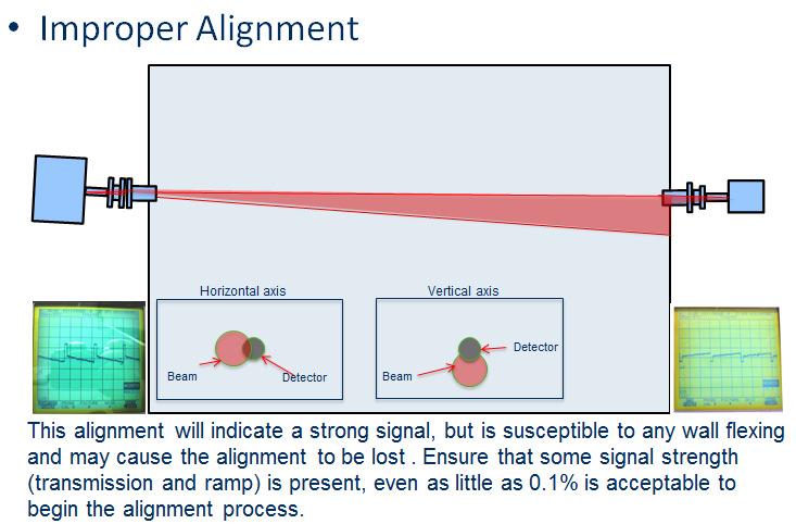
12 12 The standard flange sizes are either 2 3 or 4 150# R.F. ANSI as well as DN50 and DN80. Please check the exact flange size specified and provided for the particular installation. Other flange sizes and a variety of materials (to suit the process) are available so please check these details prior to installing the flanges on the process. The process isolation valves should have at least a 95% diameter clear bore size (aperture) to ensure there is sufficient tolerance to align the laser beam after installation. Ducts and Stacks that have thin and flexible walls should be reinforced to ensure that the laser beam alignment is maintained at all times. Rigid mounting for the process flanges is highly recommended to ensure alignment is maintained. In situations where the process flanges are mounted to these thin and flexible duct/stack walls, a larger reinforcing plate should be welded around the mounting flange area to increase the attaching region. The figure below depicts a typical suggestion however; it is the installer s responsibility to ensure appropriately rigid installation is provided for the analyzer. Below: Typical 24 x 24 x 3/8 reinforcement plate. This approach is NOT suitable for systems that use the Large Aperture Optics (LAO) detect unit, these are typically installed on applications with at least 7m (21ft) optical path length. For these long path length installations, more significant bracing and structural rigidity is required refer to following section:
13 13 Process Flange Welding Alignment and Line-Up The Launch and Detect units are provided with alignment mechanisms that allow for some manual adjustment of the laser beam direction in both planes. It is however recommended that the following angular tolerances be adhered to as closely as possible.
14 14
15 15

16 16 Details of supporting structural steel for long optical path length systems (>7m/21ft): It is important that the angle support steel (used for supporting the nozzle) be welded directly to both the walls and the adjacent heater/furnace structural steel as shown conceptually below Note; horizontal/vertical bracing tied to the adjacent structural steel and walls of the unit: Diagram below shows the preferred nozzle reinforcement method: NOTE: Ensure you have sufficient clearance behind the flange between the angle support to allow for the alignment flange and LAO attachment using appropriate nuts and bolts/studs!
17 Note: The TDLS200 flange must be at least 10 from the furnace wall. Heat will damage the optics at distances less than 10 from the furnace wall!!! The above preferred method may not be possible in every site specific situation. The actual dimensions may have to be adjusted to suit the practical installation considerations in each case but it should remain as close as possible to the above preferred method.


18 18 Case A below shows this preferred method and case B below shows an alternative method if the preferred method cannot be accommodated at the particular site installations: Above Preferred angle mounting above Alternate angle mounting Below: Image of actual installation as Case A preferred method
19 19 Mounting the Launch and Detect Units to the Process Flange Securely bolt the Launch and Detect (LAO) Units to the process flanges using the standard bolt holes/studs provided. Ensure the correct size bolts, nuts, and gasket are used in accordance with the flange specifications and in accordance with the process specifications when applicable. CAUTION: Use anti-seize paste on threads to avoid possible metallic galling on nuts/bolts/studs! START flow to the clean dry window purge gases as soon as possible if the process valve is open this will prevent contamination to the optical surfaces. Before starting the actual purge flows, ensure the lines have been blown out to remove all debris, dirt, oil, water and other media that could contaminate the optical surfaces and impaired the optical transmission/measurement performance. NOTE: the optical surface temperatures MUST NOT exceed 70degC!!! NOTE: If the process isolation valve flange is excessively hot due to the process temperature or radiant heat, then a thermal insolating flange gasket should be used in order to minimize the heat transfer to the analyzer flange face. It is generally beneficial to make the flange of the Launch and Detect Units and the flange of the process concentric with each other. Due to the large clearance provided by standard flanges and bolts, it is possible to mount the two flanges in an un-concentric manner this should be avoided to aid laser beam alignment.
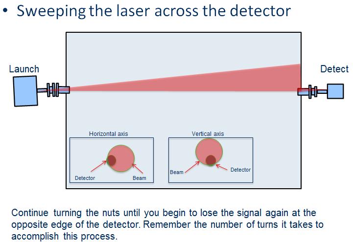
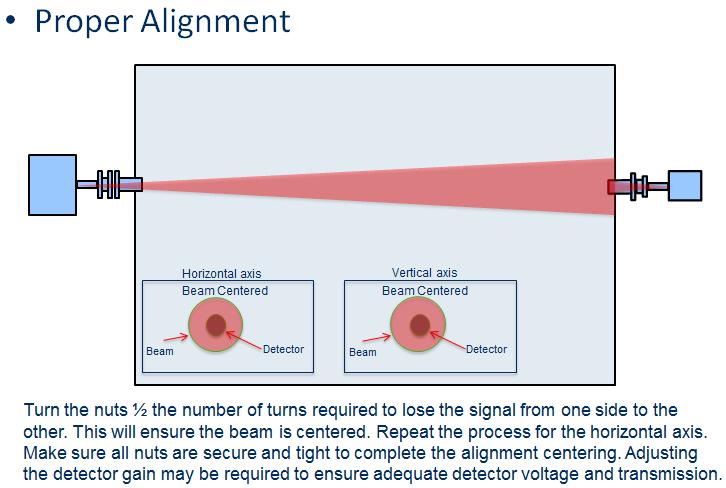
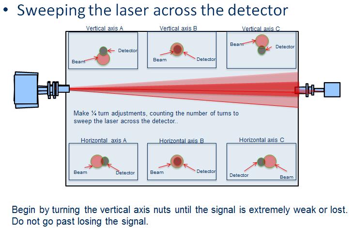
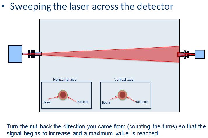
20 Adjustment and Optimization of Alignment - <600 o C (1100 o F) Installations: 3 Installation The following procedure will aide in performing an alignment of the TDLS200 analyzer. The procedure will guide the technician through the necessary steps to align and optimize the signal of the analyzer. Please read the entire procedure before starting work and ask your local Yokogawa service group for further information if required. This procedure can also be performed by local Yokogawa service personnel if required please contact for further details. The alignment of the analyzer will be accomplished by first, visually aligning the analyzer horizontally and vertically. By performing this first step, the signal should be adequate to begin the alignment procedure. Once a visual alignment is achieved and a signal is present, the optimization of the alignment will be accomplished by sweeping the launch beam across the detector beam. Alignment of the detector may be necessary to insure a signal is present. This is accomplished by monitoring the transmission strength while adjusting the top/bottom and left/right nuts on the alignment bellows. The adjustments are performed on one axis at a time. The intent is to use the alignment bellows adjustments to move the beam from one edge of the detector to the other (both horizontally and vertically), while counting the number of ¼ turns of the nuts required to sweep across the detector. The beam is then centered by taking the number of ¼ turns necessary to sweep the analyzer from one signal edge to the other and dividing this number in half and returning the analyzer to the center by turning the nuts so that the beam is centered. Example, begin by monitoring the transmission and turning the top/bottom screws so that that the beam reaches one edge of the detector, this will be noticed by a drop in transmission. Once on the edge, begin turning the nuts the opposite direction a ¼ turn at a time until you see an increase in the transmission and then a decrease and eventually a loss of transmission again. If this required 18 (¼) turns to accomplish, turn the nuts back ½ of that amount, or 9 (¼) turns to center the beam. Repeat this process for the left/right axis. The launch unit will then be centered. Please refer to the following pictorial guide for further details.
21 21


22 22 Above: Zero Transmission/No Signal Above: 0.2% Transmission/small signal
 by moving the launch around using the alignment bellows.")
23 23 Once visual alignment is achieved on both the launch and detect and clean, dry purge gas has been flowing, power may be applied to the analyzer. Begin the alignment process by starting at the launch end; maximize the signal (using the transmission signal and value) by moving the launch around using the alignment bellows. Once maximum signal is achieved, move to the detect end and using the method described in the previous slide, move the LAO/detect assembly around, until maximum signal is achieved. (Note: CO detectors are more sensitive to miss-alignment than the O2 detector)


24 24 The launch and detect alignment steps may need to be repeated several times to ensure maximum transmission. Once maximum transmission is achieved, move to the next step and ensure the laser is centered. This is done by sweeping the laser across the detector in both the horizontal and vertical axis. To accomplish this, use the nuts on the launch alignment bellows to sweep the beam.


25 25

26 26

27 27
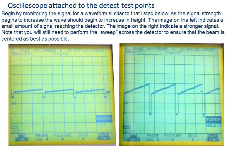
28 Adjustment and Optimization of Alignment - <1200 o C (2200 o F) Installations: This section will aide in the alignment of the large aperture optics assembly in a high temperature (i.e. with variable degree of background radiation >800 o C) application using an oscilloscope (or scope-meter). Please read the entire procedure before starting work and ask your local Yokogawa service group for further information if required. This procedure can also be performed by local Yokogawa service personnel if required please contact for further details. Please note that this procedure is not intended to teach/train someone how to use an oscilloscope! If you do not know how to use an oscilloscope, please align the analyzer by using the method mentioned in the user manual.
29 29


30 30

31 31

32 32 Once visual alignment is achieved on both the launch and detect, power may be applied to the analyzer. Begin the alignment process by starting at the launch unit to maximize the signal by moving the launch around using the alignment bellows while watching the scope screen.. Once maximum signal is achieved, (Note that the signal may be very small initially, as low as 0.1 volts) move to the detect end and using the method described in the previous slide, move the LAO/detect assembly around, until maximum signal is achieved. The launch and detect alignment steps may need to be repeated several times to ensure maximum transmission. Once maximum transmission is achieved, move to the next step and ensure the laser is centered. This is done by sweeping the laser across the detector in both the horizontal and vertical axis. To accomplish this, use the nuts on the alignment bellows to sweep the beam.

33 33
34 34

35 35

.")
36 36 Adjustment of Detector Gain after Optimization of Alignment Please read these directions carefully before attempting work and contact your local Yokogawa service center if there is any doubt about how to perform this procedure. Alternatively, Yokogawa service personnel can perform this procedure please contact you local service center for details, rates, availability, etc. INTRODUCTION Caution Electrostatic Sensitive! For TDLS200 measurement over long optical path length, the laser beam is usually configured with a small diverging angle (either with or without large aperture detector lens). In factory, the detector signal gain is not optimized for the real installation. During the analyzer field start up service, the detector gain needs to be adjusted to achieve the best analyzer performance. This document gives the guidance and procedures to adjust the detector board gain for services and customers after the analyzer is installed and powered up. This operation should be done by qualified personnel. Read instructions fully before starting this operation. Any doubts or questions, please contact Yokogawa. PHOTOS OF DETECTOR BOARD Low-temp detector board (< 600 C) High-temp detector board (> 600 C) RESISTOR KIT BAG For a TDLS200 analyzer with diverging laser beam configuration (either with or without large aperture detector lens), a resistor bag is attached inside the detector box. The resistor bag contains the resistors with the following values. All of them are ¼ W, 5% tolerance metal film through-hole resistors. Resistor Bag for Analyzers With Diverging Beam Optics Resistance (Ω) 100 1k 1.5k 2.2k 3.3k 5.1k 7.5k 11k 15.8k 24.3k Quantity

37 37 Factory gain resistors on the detector board: R21 = ; R22 = ; R23 =. PROCEDURE 1. This procedure requires wearing a grounding strap connected to one of the grounding lugs of the analyzer to prevent any electrostatic damage. 2. Open the detector enclosure and put on a grounding strap. 3. Identify the gain resistors R21, R22 and R23 on the detector board as shown in the photo above. They are all plugged in sockets instead of being soldered, easy to be modified by a pair of small pliers. The existing gain resistors have factory resistance values optimized on a calibration cell. 4. [Optional] For a high-process-temperature application and if the current process temperature is higher than 600 C, apply a multi-meter to measure the voltage across R21. If the measured voltage absolute value is greater than 5V, change R21 to the 100Ω resistor from the resistor bag. Keep the original R21 in the resistor bag as it can be used for future off-line calibration. 5. Remove R22 and R23 from the detector board and replace them with the 11kΩ resistors from the resistor bag. Please keep the original R22 and R23 in the resistor bag as they can be used for future offline calibration. 6. Optimize the analyzer alignment for both the launch and detector sides. Stop the alignment if Detector Signal High fault activates. 7. In the TruePeak user interface software, navigate to Advanced Menu (password) -> Configure -> Laser Spectra & Control screen to check the raw detector signal. Write down the raw detector signal MAX and MIN values for later use. MAX MIN 8. Change R22 and R23 accordingly based on the current raw detector signal. Perform one item of the following selections (a, b, or c). a. If Detector Signal High fault is active, change both R22 and R23 to the next smaller value available in the resistor bag, and then go back to STEP 6. For example, if the current R22 and R23 values are 11kΩ, the new R22 and R23 values should be 7.5kΩ. NOTE: please access Active Alarm in the main user interface panel to check if Detector Signal High fault is active. b. If the raw detector signal is within requirement, remove R22 and R23 (and R21 if it was changed to 100Ω in STEP 3) and cut their leads properly to fit the sockets tight and low, and then go to STEP 9. NOTE: (1) for a low-process-temperature analyzer (with no capacitor on R3), the raw detector signal is within requirement if MAX is between 0.0 and 4.0; (2) for a
38 38 high-process-temperature analyzer (with a capacitor on R3), the raw detector signal is within requirement if MIN is between -4.0 and c. If the raw detector signal is too low (other than a and b), change either R22 or R23 to the next greater value available in the resistor bag, and then go back to STEP 7. How to decide which resistor to change: i. If the current R22 value is greater than the current R23 value, change R23 to the next greater value available in the resistor bag. ii. If the current R22 value is same as the current R23 value, change R22 to the next greater value available in the resistor bag. iii. If the current R22 and R23 are already 24.3kΩ (the greatest value available in the resistor bag), please contact Yokogawa for assistance. 9. Close the detector enclosure. Write down the final values of R21, R22 and R23 below for record. R21 = ; R22 = ; R23 =. 10. Enter these new resistor values into the analyzer configuration under Advanced Menu > Configure > System > Adjustable Resistors > Detect R21, Detect R22, and Detect R23. All resistor values are entered in K ohm unit. 11. Keep the resistor bag and this procedure document by customer. DO NOT leave them in the detector box or throw them away. TIPS How to remove a gain resistor? On the detector board, find the location of the gain resistor. Please note that the resistor is not soldered but resting in sockets. Carefully remove the resistor from the socket on the board. Since the analyzer is still powered on, please take extreme caution to prevent a short circuit on the board, i.e. loose wires or touching adjacent components with pliers or tool used to remove resistor. How to install a new gain resistor? First try the new resistor by molding and clipping the resistor leads to fit into the socket. Then carefully insert the resistor into the socket on the detector board. Since the analyzer is still powered on, please take extreme caution to prevent a short circuit on the board, i.e. loose wires or touching adjacent components with pliers or tool used to install resistor. Please keep the factory/original gain resistors in the resistor bag as they will be used in the future for offline calibration or test. The raw detector signal (MAX-MIN) is proportional to R21 R22 R23. Usually R21 is maintained as factory value. R22 and R23 are optimized in the field. We want to avoid the situation where one of R22 and R23 resistors has extreme low resistance and the other one has extreme high resistance. The analyzer gives best performance when R22 and R23 are balanced. Based on this relation between raw detector signal and gain resistors, service technician or customer can select R22 and R23 faster with the help of a calculator. Multiple alignment actions might be needed if Detector Signal High fault happens. Reduce the gain resistor first as described in STEP 8-a, and then optimize the alignment again. NOTE: If the alignment has been performed on a cold (shut-down) heater/furnace, then it is highly recommended when the heater/furnace is at normal operating temperature, the transmission/alignment be checked again to ensure >10% (ideally >25%) transmission exists and that there are no alarms. Validation gas should also be introduced through the validation cell to ensure peak response, especially if a line-locking gas is not being used.
39 39 4 Contact for Further Assistance Should you require any further information or details not contained herein, then please contact your local Yokogawa Office, Yokogawa Distributor or Yokogawa Sales Representative or Yokogawa Laser Analysis Division directly as listed below: Yokogawa Laser Analysis Division 910 Gemini Street Houston, Texas USA Telephone: Facsimile: SERVICE: (USA toll free) Service: website: TDLS website: support@us.yokogawa.com
New Features TDLS 200. The Process TDLS Solution. Tunable Diode Laser Spectroscopy (TDLS) Analyzer.
 Analyzer.") The Process TDLS Solution New Features TDLS 200 Tunable Diode Laser Spectroscopy (TDLS) Analyzer Bulletin 11Y01B01-01E-A www.yokogawa.com/an/index.htm The first Tunable Diode Laser analyzer Innovative
The Process TDLS Solution New Features TDLS 200 Tunable Diode Laser Spectroscopy (TDLS) Analyzer Bulletin 11Y01B01-01E-A www.yokogawa.com/an/index.htm The first Tunable Diode Laser analyzer Innovative
Operation and Maintenance Manual
 Operation and Maintenance Manual GDS-48 Remote Bridge Sensor for Combustible Gases AUTHORIZED DISTRIBUTOR: GasDetectorsUSA.com - Houston, Texas USA sales@gasdetectorsusa.com - 832-615-3588 CAUTION: FOR
ISO Acceptance tests for Nd:YAG laser beam welding machines Machines with optical fibre delivery Laser assembly
 INTERNATIONAL STANDARD ISO 22827-1 First edition 2005-10-15 Acceptance tests for Nd:YAG laser beam welding machines Machines with optical fibre delivery Part 1: Laser assembly Essais de réception pour
BP Alaska GC-1. Design Review Project. January 2003
 BP Alaska GC-1 Design Review Project January 2003 January 03 _03 January BP Alaska GC-1 Design Review Project I. Statement of requirement The objective of this report is to review the current design drawings
CombustionONE. Improving and Sustaining the Combustion Asset. Driven by the New Standards. Bulletin 53A90A01-01E-A
 1 CombustionONE TM Improving and Sustaining the Combustion Asset Driven by the New Standards Bulletin 53A90A01-01E-A 1 CombustionONE Improving and Sustaining the Combustion Asset TM Yokogawa Corporation
THEORY OR OPERATION 2 SENSOR UNIT - MECHANICAL 6 SENSOR UNIT - ELECTRICAL 8 CONTROL UNIT - MECHANICAL 9 CONTROL UNIT - ELECTRICAL 9 OPTIONS 11
 Table of Contents INTRODUCTION 1 THEORY OR OPERATION 2 DESCRIPTION 5 SENSOR UNIT - MECHANICAL 6 SENSOR UNIT - ELECTRICAL 8 CONTROL UNIT - MECHANICAL 9 CONTROL UNIT - ELECTRICAL 9 SPECIFICATIONS 10 OPTIONS
Duct Heaters volts/1 phase volts/3 phase volts/3 phases volts/3 phases. Flange Type Duct Heater.
 Duct Heaters Synheat duct heaters come in various sizes and dimensions to fit any compartment. There are three types of duct heaters available: open coil, tubular element or finned tubular heating elements
THE STANDARD OF EXCELLENCE WDG-V SERIES COMBUSTION ANALYZERS
 THE STANDARD OF EXCELLENCE WDG-V SERIES COMBUSTION ANALYZERS A Worldwide Manufacturer of Process Analyzers and Instrumentation RELIABILITY EXPERIENCE SOLUTIONS AMETEK Process Instruments is a worldwide
HYDROCARBONENGINEERING June June 2015
 www.hydrocarbonengineering.com Controlled Combustion Arthur Groenbos, Yokogawa Europe, discusses tunable diode laser gas analysis for combustion management in fired heaters. While fired heaters are used
Laser Distance Sensor Type M Analog-Output
 Laser Distance Sensor Type M Analog-Output Operating Manual Version 2.3, May 2009 ELAG Elektronik AG l Stegackerstrasse 14 l CH-8409 Winterthur Contents 1. Safety 1.1 Laser safety 1.2 Electrical safety
T3/E3 Fiber Optic Line Drivers
 MT618A-ST-R3 January 2004 MT619A-ST-R2 MT620AE-R2 T3/E3 Fiber Optic Line Drivers CUSTOMER SUPPORT INFORMATION Order toll-free in the U.S.: Call 877-877-BBOX (outside U.S. call 724-746-5500) FREE technical
End To End Optical Beam Smoke Detector. Additional Information
 End To End Optical Beam Smoke Detector Additional Information EN 1. Multiple Zone Wiring When using more than one System Controller on a single zone of a conventional Fire Control Panel (FCP), it is important
Models TX-KE and TX-KP Toxic Gas Transmitters
 Models TX-KE and TX-KP Toxic Gas Transmitters Instruction Manual PureAire Monitoring Systems, Inc. 557 Capital Dr. Lake Zurich, IL. 60047 Phone: 847-726-6000 Fax: 847-726-6051 Toll-Free: 888-788-8050 www.pureairemonitoring.com
PIP PCTPA001 Testing of Process Analyzer Systems
 January 2016 Process Control PIP PCTPA001 Testing of Process Analyzer Systems PURPOSE AND USE OF PROCESS INDUSTRY PRACTICES In an effort to minimize the cost of process industry facilities, this Practice
Installation and Operating Instructions ISH ELECTRIC STEAM SUPERHEATER
 Installation and Operating Instructions ISH ELECTRIC STEAM SUPERHEATER 1 Installation and Operating Instructions ISH ELECTRIC STEAM SUPERHEATER FOR YOUR SAFETY This manual supplies information on the application,
Advance Optima Module Magnos 17
 Advance Optima Module Magnos 17 Service Manual 43/24-1002-0 EN Table of Contents Page Chapter 1: Description of functions 1-1 Chapter 2: Module variants and components 2-1 Chapter 3: Analyzer variants
Thank You for Attending Today s Webinar:
 Detect, Measure, Analyze. Thank You for Attending Today s Webinar: Oxygen Measurement in Safety Critical Applications Your Host Jim Behnke Sales RAECO-LIC LLC jim@raeco.com Featured Speaker Sr Strategic
ENRGY CURB APPLICATION GUIDE FOR TPO ROOFING SYSTEMS
 1. Introduction The ENRGY Curb mounting system is a lightweight, nonpenetrating, roof-integrated, photovoltaic (PV) mounting system designed to maintain roof integrity and maximize power density. This
SIMRAD GD10PE IR GAS DETECTOR
 SIMRAD GD10PE IR GAS DETECTOR Operating Manual P3404E 1st edition Jan. 2004 www.simrad-optronics.com CONTENTS 1. PRODUCT DESCRIPTION... 5 1.1 General description... 5 1.2 Construction... 5 1.3 Application
Model gffoz Process Ozone Sensor (In-Line)
") Date ECO# Rev Description Originator 9/15/97 1.0 First Publication DB 10/8/97 2.0 Miscelaneous corrections DB 10/28/97 3.0 Minor changes BM 5/1/98 3.1 Added CE compliance BM TM IN USA, INCORPORATED 87
Date ECO# Rev Description Originator 9/15/97 1.0 First Publication DB 10/8/97 2.0 Miscelaneous corrections DB 10/28/97 3.0 Minor changes BM 5/1/98 3.1 Added CE compliance BM TM IN USA, INCORPORATED 87
INSTALLATION INSTRUCTIONS FOR 6532 SERIES PACKAGE HEAT PUMP
 INSTALLATION INSTRUCTIONS FOR 6532 SERIES PACKAGE HEAT PUMP RV Products A Division of Airxcel, Inc. P.O. Box 4020 Wichita, KS 67204 1976-360 (1-02) PP TABLE OF CONTENTS 1. Warnings......................................................
SAMPLE SPECIFICATIONS CONTINUOUS MONITORING SYSTEM (Insitu)
") PART 1 - GENERAL A. RELATED DOCUMENTS SAMPLE SPECIFICATIONS CONTINUOUS MONITORING SYSTEM (Insitu) Federal, State, and local requirements as applicable. Attached Permit Attached drawings B. SUMMARY 1. Provide
PART 1 - GENERAL A. RELATED DOCUMENTS SAMPLE SPECIFICATIONS CONTINUOUS MONITORING SYSTEM (Insitu) Federal, State, and local requirements as applicable. Attached Permit Attached drawings B. SUMMARY 1. Provide
OPERATING AND MAINTENANCE MANUAL
 OPERATING AND MAINTENANCE MANUAL NVPOM-0104 TABLE OF CONTENTS Section Page 1 SPECIFICATIONS...1 1.1 Nova Plus Specifications...1-1 1.2 Warranty...1-2 2 GENERAL BURNER DESCRIPTION...2 2.1 Burner...2-1 2.2
Vibration Of Cooling Tower Fans. Barry T. Cease Cease Industrial Consulting Vibration Institute 2015
 Vibration Of Cooling Tower Fans Barry T. Cease Cease Industrial Consulting Vibration Institute 2015 ceasevibration@icloud.com (843) 200-9705 1 WHAT IS A COOLING TOWER AND WHAT DOES IT DO? All cooling towers
INSTALLATION AND OPERATION MANUAL FOR 2 STAGE RIELLO BURNER ADDENDUM TO ( Mo 437 manual )
") INSTALLATION AND OPERATION MANUAL FOR 2 STAGE RIELLO BURNER ADDENDUM TO ( Mo 437 manual ) FOR USE WITH MODEL: OH6FX072DV4 PLEASE READ THESE INSTRUCTIONS PRIOR TO INSTALLATION, INITIAL FIRING, AND BEFORE
INSTALLATION AND OPERATION MANUAL FOR 2 STAGE RIELLO BURNER ADDENDUM TO ( Mo 437 manual ) FOR USE WITH MODEL: OH6FX072DV4 PLEASE READ THESE INSTRUCTIONS PRIOR TO INSTALLATION, INITIAL FIRING, AND BEFORE
IMPORTANT. PLEASE NOTE: The infrared beam path MUST be kept clear of obstructions at all times!
 USER GUIDE English IMPORTANT PLEASE NOTE: The infrared beam path MUST be kept clear of obstructions at all times! Failure to comply may result in the Detector initiating a Fire or Fault signal. Contents
SEC Signature Process Gas Analyzer
 SEC Signature Process Gas Analyzer Instruction and Operation Manual Sensor Electronics Corporation 5500 Lincoln Drive Minneapolis, Minnesota 55436 USA (952) 938-9486 Fax (952) 938-9617 email sensor@minn.net
FPD - Flame Photometric Detector
 FPD - Flame Photometric Detector FPD Overview - The FPD detector is can be configured for 2 modes of operation, one is highly selective for Sulfur compounds and the other mode highly selective for Phosphorus
INTERNATIONAL STANDARD
 INTERNATIONAL STANDARD IEC 60825-1 1993 AMENDMENT 2 2001-01 PUBLICATION GROUPÉE DE SÉCURITÉ GROUP SAFETY PUBLICATION Amendment 2 Safety of laser products Part 1: Equipment classification, requirements
Ensuring the Health of Tomorrow s Fiber LANs Part II OTDR Trace Analysis Become an Expert Troubleshooter with Advanced OTDR Trace Analysis
 Ensuring the Health of Tomorrow s Fiber LANs Part II OTDR Trace Analysis Become an Expert Troubleshooter with Advanced OTDR Trace Analysis Experience designing cable and network testers has enabled a breakthrough
USERS MANUAL FOR GAS BOILERS
 USERS MANUAL FOR GAS BOILERS PLEASE READ THE MANUAL CAREFULLY: IT CONTAINS IMPORTANT INFORMATION REGARDING SAFETY, INSTALLATION, USE AND MAINTENANCE OF THE APPLIANCE MODELS: NOVADENS 24 NOVADENS 24C NOVADENS
Specifications. Table of contents. 2:Specification. 3:Composition. 4:Instruments outside figure
 DUST DENSITY METER (DDM-2001) Specifications Table of contents 1:Outline 2:Specification 3:Composition 4:Instruments outside figure 1) Main body control box 2) Detector 3) Optical fiber cable 4) Purge
Installation Instructions
 Installation Instructions KFN 9855 ide en - CA Installation, repair and maintenance work should be performed by a Miele authorized service technician in accordance with national and local safety regulations
C7007A, C7008A, C7009A Flame Rod Holder & Flame Rod Assemblies
 Flame Rod Holder & Flame Rod Assemblies The small size of these devices enable their application to flame detection in installations where space is limited. The holder and flame rod assemblies facilitate
CONTROL BE MADE CHANGES MAY NOT. Page 1
 HI 6020IT and HI 6020JB US & Canada Hazardous Locations User Guide (Class I, II, III, Division 1, Class I, Zone 0 and Zone 20) Hardy Process Solutions Document Number: : 0596-0352-01 REV A CONTROL LLED
Approval Standard for Electric Equipment for use in Hazardous (Classified) Locations General Requirements
 Locations General Requirements") Approval Standard for Electric Equipment for use in Hazardous (Classified) Locations General Requirements Class Number 3600 November 1998 2002 FM Approvals LLC. All rights reserved. Foreword FM Approvals
Approval Standard for Electric Equipment for use in Hazardous (Classified) Locations General Requirements Class Number 3600 November 1998 2002 FM Approvals LLC. All rights reserved. Foreword FM Approvals
Steam Trap BK 45 BK 45-U BK 45-LT BK 46
 Steam Trap BK 45 BK 45-U BK 45-LT BK 46 Original Installation Instructions 810437-08 Contents Foreword... 3 Availability... 3 Formatting features in the document... 3 Safety... 3 Use for the intended purpose...
INTRODUCTION THIS MANUAL INCLUDES IMPORTANT SAFETY INFORMATION
 INSTALLATION AND OPERATING INSTRUCTIONS FOR THE HARDY Fuel Oil Furnace Models D-140 & D-350 HARDY MANUFACTURING COMPANY, INC. 12345 ROAD 505 PHILADELPHIA, MS 39350 PHONE: (601) 656-5866 FAX: (601) 656-4559
International comparison of validation methods for dust concentration measurement
 International comparison of validation methods for dust concentration measurement Validation of dust monitors can be divided into 2 steps: 1. Validation of a generic dust monitor as an instrument (Type
Snifter ATEX22 VERSION. User Manual. Distributor
 Snifter ATEX22 VERSION User Manual Distributor Version 1.4 09/09/2009 Table of Contents 1. INTRODUCTION... 3 1.1. Safety... 3 1.2. Product overview... 4 1.3. How does it work?... 4 2. INSTALLATION... 5
Instruction Manual. Self-Leveling Combination Cross-Line Laser and Five-Beam Laser Dot Model No &
 6339H_Manuals 10/24/12 12:56 PM Page 1 Self-Leveling Combination Cross-Line Laser and Five-Beam Laser Dot Model No. 40-6685 & 40-6687 Instruction Manual Congratulations on your choice of this Self-Leveling
Instruction Manual. Self-Leveling Combination Cross-Line Laser and Five-Beam Laser Dot Model No , &
 1622i_Manuals 12/14/16 12:52 PM Page 1 Self-Leveling Combination Cross-Line Laser and Five-Beam Laser Dot Model No. 40-6685, 40-6687 & 40-6688 Instruction Manual Congratulations on your choice of this
Exhaust Duct Design Page 1 of (C)
") Exhaust Duct Design Page 1 of 16 2016-10-07 (C) Oven Exhaust Guide Version: R5 Exhaust Duct Design The following section is for your guidance in establishing a design to suit your Exhaust duct design requirements.
Exhaust Duct Design Page 1 of 16 2016-10-07 (C) Oven Exhaust Guide Version: R5 Exhaust Duct Design The following section is for your guidance in establishing a design to suit your Exhaust duct design requirements.
INDITHERM. Low temperature gas burners
 INDITHERM Low temperature gas burners 1-2.3-1 High turndown for maximum operation flexibility. Maximum capacities up to 1800 kw. Designed for firing in indirect fired processes. Excellent combustion throughout
Important Safety Notice
 Date: 27 th April 2015 Page 1 of 12 SPI Lasers UK Limited Safety Information High Power OEM Fibre Lasers Important Safety Notice This notice outlines important safety related information and must be read
Approved by Principal Investigator: Date: Approved by Laser Safety Officer: Date:
 Black Text is considered mandatory content Red text fill in appropriate information for factual accuracy Blue Text (sample text) may be retained, edited, or deleted as appropriate for factual accuracy
EEM 451 Industrial Control Systems Sensors and Actuators-II. Dept. of Electrical-Electronics Eng. Anadolu University, Turkey
 EEM 451 Industrial Control Systems Sensors and Actuators-II Hakkı Ulaş Ünal Dept. of Electrical-Electronics Eng. Anadolu University, Turkey Sensors In order to monitor, control the process variables, sensors
Chapter 17, Initiating Devices
 Chapter 17, Initiating Devices Summary. Chapter 17 was Chapter 5 in NFPA 72-2007. The term authority having jurisdiction is replaced in some sections by the term other governing laws, codes, or standards.
WATLOW IND. WATROD Flange Heater Installation & Maintenance Manual I&M NUMBER: Page: 1 Date:6/11/2008 Rev: 2.00
 I&M NUMBER: 316-42-8-1 Page: 1 _ Pre Installation Check to make sure that heater received is the same as that ordered. Elements may come in contact with each other during shipment. Minor adjustments to
Powerohm Resistors Digital HRG System
 Installation and Operating Instructions Powerohm Resistors Digital HRG System This manual provides general information, installation, operation, maintenance, and system setup information for the Powerohm
LFE50. UV Flame Safeguard. Building Technologies Division DETACTOGYR
 7 783 DETACTOGYR Flame Safeguard The... together with the QRA50M / QRA51M form a self-checking flame supervision system (DETACTOGYR ) designed for use with continuously operating oil or gas burners or
Operation/Maintenance BLOWER OVERHEAD Ionizing Air Blower
 IONIZING AIR BLOWER MODEL:QUICK442 INSTRUCTIONS Operation/Maintenance BLOWER OVERHEAD Ionizing Air Blower The Ionizing AIR BLOWER (OVERHEAD) is a member of the ionizing air blower family. The BLOWER OVERHEAD
PRODUCT CONFORMITY CERTIFICATE
 PRODUCT CONFORMITY CERTIFICATE This is to certify that the D-R 290 Opacity and Dust Concentration Monitor manufactured by: DURAG GmbH Kollaustraße 105 22453 Hamburg Germany has been assessed by Sira Certification
Understanding total measurement uncertainty in power meters and detectors
 Understanding total measurement uncertainty in power meters and detectors Jay Jeong, MKS Instruments. Inc. INTRODUCTION It is important that users of calibrated power meters and detectors understand and
WATLOW IND. FIREBAR Flange Heater Installation & Maintenance Manual I&M NUMBER: Page: 1 Date: 6/11/2008 Rev: 2.00
 I&M NUMBER: 316-42-2-1 Page: 1 Pre Installation Check to make sure that heater received is the same as that ordered. Elements may come in contact with each other during shipment. Minor adjustments to elements
Product Overview. Ordering Information DM-LK-D10 DM-LK-D10-C. Dust & Opacity Meter Complete Set Controller Unit. Sender Receiver SDS-V5 SDR-V4 HPB-82S
 D10 is a type-approved measuring device which combines the advantages of the measuring principles transmittance and scattered light forward. Therefore, it is ideal for measurement of very low to high dust
Mineral Insulated Band Heater
 The MI band heater is a high-performance heater. Its performance and name are derived from exclusive mineral insulation a material with much higher thermal conductivity than mica and hard ceramic insulators
INSTALLATION INSTRUCTIONS & HOME OWNERS MANUAL ECO 18 ECO 24 ECO 27 IMPORTANT SAFETY INFORMATION
 INSTALLATION INSTRUCTIONS & HOME OWNERS MANUAL ECO 18 ECO 24 ECO 27 IMPORTANT SAFETY INFORMATION As when installing or using any high voltage electrical appliance, basic safety precautions should always
Zircomat Oxygen Analyzers
 Zircomat Oxygen Analyzers Finally Hassle Free Stack Gas Oxygen Measurement Many of the top fortune 500 companies have already discovered that installing a ZIRCOMAT Oxygen analyzer is the smart way to measure
RK-OXY Oxygen Sample-Draw Detector Operator s Manual Part Number: RK Revision: P1 Released: 7/18/02
 35-3000RK-OXY Oxygen Sample-Draw Detector Operator s Manual Part Number: 71-0071RK Revision: P1 Released: 7/18/02 RKI Instruments Inc. 1855 Whipple Road Hayward, CA 94544 PH: 800-754-5165 Fax: 510-441-5650
B.C.S. Shop Heaters 26, 30 & 36 (36 shown)
") BIOMASS COMBUSTION SYSTEMS, INC. 67 MILLBROOK ST., SUITE 502 WORCESTER, MA 01606 508-798-5970 - FAX 508-798-5971 B.C.S. Shop Heaters 26, 30 & 36 (36 shown) INSTALLATION MANUAL HAND FIRED SYSTEMS 8-09 Biomass
BIOMASS COMBUSTION SYSTEMS, INC. 67 MILLBROOK ST., SUITE 502 WORCESTER, MA 01606 508-798-5970 - FAX 508-798-5971 B.C.S. Shop Heaters 26, 30 & 36 (36 shown) INSTALLATION MANUAL HAND FIRED SYSTEMS 8-09 Biomass
SuperOX TM Oxygen Sensor U.S. Patent No. 5,635,044
 SuperOX TM Oxygen Sensor U.S. Patent No. 5,635,044 Operations Manual Super Systems Inc. 7205 Edington Drive Cincinnati, OH 45249 513-772-0060 800-666-4330 Fax: 513-772-9466 www.supersystems.com Table of
HX Field Replacement Kit
 Quantity Kit Part Number Description PE 110 Natural Gas Stainless Steel Condensate Pan PT 110 Natural Gas Polypropylene Condensate Pan Model PE 110 LP Stainless Steel Condensate Pan PT 110 LP Polypropylene
Model 6650SP. Filber Optic-Based UV-Fluorescence Oil-in-Water Analyzer
 Model 6650SP Filber Optic-Based UV-Fluorescence Oil-in-Water Analyzer 6650SP - OVERVIEW The Model 6650SP is the next generation in-water Analyzer. The 6650SP incorporates the most advanced, state-of-the-art
IONIZING AIR BLOWER INSTRUCTION MANUAL
 IONIZING XC AIR BLOWER INSTRUCTION MANUAL Thank you for purchasing this XC Ionizing Air Blower. It is designed to eliminate the static electricity from a charged object. Please read this manual before
Optical Time Domain Reflectometry (OTDR)
") Experimental Optics Contact: Helena Kämmer (helena.kaemmer@uni-jena.de) Last edition: Helena Kämmer, January 2017 Optical Time Domain Reflectometry (OTDR) Contents 1 Overview 3 2 Safety issues 3 3 Theoretical
Experimental Optics Contact: Helena Kämmer (helena.kaemmer@uni-jena.de) Last edition: Helena Kämmer, January 2017 Optical Time Domain Reflectometry (OTDR) Contents 1 Overview 3 2 Safety issues 3 3 Theoretical
LFE50. UV Flame Safeguard. Siemens Building Technologies HVAC Products DETACTOGYR. Series 02
 7 783 ISO 9001 DETACTOGYR Flame Safeguard Series 02 The... together with the QRA50M / QRA51M form a self-checking flame supervision system (DETACTOGYR ) designed for use with continuously operating oil
Stony Brook University Hospital Environmental Health & Safety Policy & Procedure Manual. EH&S 6-8 Original : 1/00 Revision Date: 3/16/15 Pages 6
 Title: Laser Safety Stony Brook University Hospital Environmental Health & Safety Policy & Procedure Manual EH&S 6-8 Original : 1/00 Revision Date: 3/16/15 Pages 6 PURPOSE: SCOPE: To protect University
IRtech. E instruments. IRtech Radiamatic IR20 LS series. Infrared Technology
 E instruments IRtech Temperature range up to 2200 C Optical resolution up to 300:1 Close focus 0,5mm 8-14µm, 1.6µm, 1µm, 2.3µm, 3.9µm, 4.2µm, 4.6µm, 5.1µm and 7.9µm Spectral response Dual laser true target
LONGONI ENGINEERING SRL
 INDEX 1.1 Classification of heat exchanger and components 1.1.2 Type of heat exchanger and components 1.2 Purpose and scope of the manual 1.3 General instruction 1.4 Warning installation 1.5 Notes for
Motorised Infrared Optical Beam Smoke Detector. User Guide
 Motorised Infrared Optical Beam Smoke Detector User Guide EN 1. General Information 50cm 50cm 8-100m Ensure clear line of sight from Detector to Reflector Mount on solid surfaces (structural wall or girder)
Fiber Optic Cable Fence Disturbance Sensor
 Architectural & Engineering Specification for Fiber Optic Cable Fence Disturbance Sensor Purpose of document This document is intended to provide performance specifications and operational requirements
B-40/B-41 Modulating Temperature Controller
 INSTALLATION & OPERATING INSTRUCTIONS B-40/B-41 Modulating Temperature Controller For Raytherm Boilers & Water Heaters H2 514-4001 WH2 2100-4001 Catalog No. 5000.70 Effective: 12-21-11 Replaces: NEW P/N
Technical specifications of FT-IR Spectrometer
 Technical specifications of FT-IR Spectrometer We would like to buy a FT-IR spectrometer which has to be integrated with a Gas Chromatograph with the following technical specifications. 1. The spectrometer
Installation Instructions U-RAD-LT Electric Radiant Heaters
 Installation Instructions U-RAD-LT Electric Radiant Heaters 1 PG421-2 161-058006-001 May 2016 2 U-RAD-LT Electric Radiant Heaters The Safety Alert Symbol is used to indicate a risk of personal injury.
Approved by Principal Investigator: Date: Approved by Laser Safety Officer: Date:
 Approved by Principal Investigator: Date: Approved by Laser Safety Officer: Date: Standard Operating Procedure Hildebrand Hall Room B70 Coherent Genesis MX Optically Pumped Semiconductor (OPS) Laser (514
Inverted Bucket Steam Traps
 INSTALLATION AND MAINTENANCE INSTRUCTIONS IM-2-00-US December 201 Inverted Bucket Steam Traps Safety Information Safe operation of these products can only be guaranteed if they are properly installed,
SCD. SMALL CYLINDER DRYER with Touchscreen Controller INSTRUCTION MANUAL MANUAL NUMBER Issued March 2015
 SCD SMALL CYLINDER DRYER with Touchscreen Controller INSTRUCTION MANUAL MANUAL NUMBER 21-11-1042 Issued March 2015 Copyright 2015, Galiso, Inc. 22 Ponderosa Ct., Montrose, CO 81401 (970) 249-0233 (800)
INSTALLATION, OPERATING & MAINTENANCE INSTRUCTIONS FOR 870 SERIES INDUSTRIAL CONTROL PANELS
 INSTALLATION, OPERATING & MAINTENANCE INSTRUCTIONS FOR 870 SERIES INDUSTRIAL CONTROL PANELS GENERAL INDEECO Industrial Control Panels are designed to provide years of trouble free operation if properly
PRODUCT INFORMATION. GM901 Carbon Monoxide Gas Analyzers CO MEASUREMENT FOR EMISSION MONITORING AND PROCESS CONTROL. In-situ Gas Analyzers
 PRODUCT INFORMATION GM901 Carbon Monoxide Gas Analyzers CO MEASUREMENT FOR EMISSION MONITORING AND PROCESS CONTROL In-situ Gas Analyzers MONITORING CARBON MONOXIDE EMISSIONS INNOVATIVELY AND EFFICIENTLY
IMR 5000 Operating Manual S/N: SAMPLE For information only! IMR Environmental Equipment Inc.
 IMR 5000 Operating Manual S/N: For information only! IMR Environmental Equipment Inc. INTRODUCTION 3 SAFETY INSTRUCTIONS 3 SYSTEM DESCRIPTION - IMR 5000 GAS ANALYSIS SYSTEM 4 Function chart IMR 5000 -
Procedure for the Approval of New Fire Detection and Alarm Technologies
 VdS Guidelines for Automatic Fire Detection and Fire Alarm Systems VdS 3469en Procedure for the Approval of New Fire Detection and Alarm Technologies VdS 3469en : 2016-01 (01) Publisher and publishing
Motorised Infrared Optical Beam Smoke Detector. User Guide
 Motorised Infrared Optical Beam Smoke Detector User Guide EN 1. General Information 50cm 50cm 8-100m Ensure clear line of sight from Detector to Reflector Mount on solid surfaces (structural wall or girder)
OPERATION INSTRUCTION
 IONIZING AIR BLOWER PC OPERATION INSTRUCTION Thank you for purchasing this PC Ionizing Air Blower. It is designed to eliminate the static electricity from a charged object. Please read this manual before
! The Caution Symbol (exclamation point) alerts you to a "CAUTION", a safety or
 alerts you to a CAUTION, a safety or") I&M NUMBER: 316-42-10-1 Page: 1 Pre Installation Check to make sure that heater received is the same as that ordered. Elements may come in contact with each other during shipment. Minor adjustments to
I&M NUMBER: 316-42-10-1 Page: 1 Pre Installation Check to make sure that heater received is the same as that ordered. Elements may come in contact with each other during shipment. Minor adjustments to
FUSION ALARMS TROUBLESHOOTING GUIDE CURRENT LIMIT VOLTAGE LIMIT
 1 FUSION ALARMS TROUBLESHOOTING GUIDE CURRENT LIMIT Description: Controller is limiting the load current to the current limit set on the controller. Display: CURRENT LIMIT Alarm Reset Action: Automatically
Process Control PIP PCEA001 Fixed Gas Detection Guidelines
 November 2015 Process Control PIP PCEA001 PURPOSE AND USE OF PROCESS INDUSTRY PRACTICES In an effort to minimize the cost of process industry facilities, this Practice has been prepared from the technical
INSTALLATION, OPERATING & MAINTENANCE INSTRUCTIONS FOR 350 SERIES CIRCULATION HEATERS
 INDEECO Circulation Heaters are designed to provide years of trouble free operation if properly installed and maintained. Please read and follow these instructions for installing and maintaining the heater.
Laser Safety Management
 Properties of Laser light Laser Safety Management Danny Fok Monochromatic (single wavelength) Directional (almost parallel low angular divergency) Coherent (in phase) Pulse or continuous Beam can be focused
RK Multi Point Detector Operator s Manual
 65-2480RK Multi Point Detector Operator s Manual Part Number: 71-0198RK Revision: C Released: 11/26/14 RKI Instruments, Inc. www.rkiinstruments.com WARNING Read and understand this instruction manual before
Safe Operation Manual. Honeywell IQ Force Gas Detector
 Safe Operation Manual Honeywell IQ Force Gas Detector Honeywell Analytics 800-663-4164 403-248-9226 Fax 403-575-3708 03JUN2012 P/N 50105843-047 Version 01 http://www.honeywell.com HONEYWELL IQ Force PERSONAL
Multi-Function Cooktop
 INSTALLATION GUIDE Multi-Function Cooktop Contents Wolf Multi-Function Cooktop.................... 3 Multi-Function Cooktop Specifications............ 4 Multi-Function Cooktop Installation...............
Tune-Rite Software Operation Manual
 Software Operation Manual P/N: 0024-9504 Revision 0 July 2014 Product Leadership Training Service Reliability Table of Contents SECTION 1. INTRODUCTION... 3 SECTION 2. SAFETY... 4 2.1. Conventions... 4
IMR 5000 IMR 400. CEMS Operating Manual IMR USA S/N: Sample IMR Sensors Inside IMR 400. Gas Dryer Inside. IMR Environmental Equipment Inc.
 CEMS Operating Manual IMR USA S/N: Sample IMR 5000 IMR 400 IMR 400 IMR 5000 Measure MESURE PURGE Purge CALIBRATE Calibrate OFF OFF RESET Measure ON ON Calibrate RESET PUMP Gas Dryer Inside PUMP Sensors
Class 1 laser beam sensor safe for your eyes
 1129 PHOTO PHOTO PARTICUR Sensor SERIES Related Information General terms and conditions... F-3 About laser beam... P.193~ guide... P.121~ General precautions... P.19 Conforming to FDA regulations (-11
USER INSTRUCTIONS FOR FLANGE IMMERSION HEATERS USED IN HAZARDOUS LOCATIONS
 USER INSTRUCTIONS FOR FLANGE IMMERSION HEATERS USED IN HAZARDOUS LOCATIONS APPLICATION INDEECO Explosion proof Electric Immersion Heaters for Hazardous Locations are ccsaus Certified for use in areas (external
Class 1 laser beam sensor safe for your eyes
 113 Sensor SERIES Related Information General terms and conditions... F-7 About laser beam... P.199~ Sensor selection guide... P.1~ General precautions... P.11 PHOTO PHOTO PARTICUR MEASURE ITY panasonic.net/id/pidsx/global
Ozone Generator and Ozone PCB Tests and Fault Troubleshooting
 September 2015, SOM PAGE 1 T003. Ozone Generator and Ozone PCB Tests and Fault Troubleshooting Ozone Generator and Ozone PCB Tests and Fault Troubleshooting For specific details of the BioTector analyzer
C37. ECL Comfort. User's Guide. Installer's Guide. ECL Comfort C37. User's Guide. Installer's Guide *VI7CE602* *087R8070* *087R8070* *VI7CE602*
 User's Guide VI.7C.E6.02 2005.09 C37 *VI7CE602* *087R8070* www.danfoss.com ECL Comfort User's Guide ECL Comfort Installer's Guide www.danfoss.com *087R8070* *VI7CE602* Mixing controller with ON / OFF controlled
SECTION AUTOMATIC TRANSFER SWITCHES
 SECTION 26 36 23 AUTOMATIC TRANSFER SWITCHES PART 1 - GENERAL 1.1 RELATED DOCUMENTS A. General provisions of the Contract, including General and Supplementary Conditions and Division 01 Specification Sections,