HB-1D Hybridisation oven
|
|
|
- Austin Roberts
- 5 years ago
- Views:
Transcription

1 HB-1D Hybridisation oven OPERATOR S MANUAL Issue 27 11/2014
2 2
3 CONTENTS INTRODUCTION... 5 BEFORE USE... 6 Unpacking...6 SAFETY AND INSTALLATION... 7 Warning...7 Operator Safety...7 Installation...7 Environmental Conditions...8 Guarantee...8 SÉCURITÉ ET CONSIGNES D INSTALLATION... 9 Avertissement...9 Sécurité de l opérateur...9 Installation...9 Conditions environnementales Garantie SICHERHEITS- UND INSTALLATIONSINFORMATIONEN Achtung Sicherheit des Bedienpersonals Inbetriebnahme Umweltbedingungen Garantie INFORMAZIONI SULLA SICUREZZA E L'INSTALLAZIONE Avvertenza Sicurezza dell'operatore Installazione Condizioni ambientali Garanzia INFORMACIÓN DE SEGURIDAD E INSTALACIÓN Advertencia Seguridad del operario Instalación Condiciones ambientales Garantía CONTACT INFORMATION SPECIFICATIONS INSTALLATION OPERATION Switching On The front panel controls Setting the speed Setting the temperature Indicators Hybridisation tubes Installing the hybridisation tubes Basic protocol for Southern Hybridisations Warning User maintenance ADDITIONAL INFORMATION Fault Finding Fuses Safety over-temperature cut-out If an incorrect message is displayed Insulation testing
4 Support contacts SPARES AND ACCESSORIES DECLARATION OF CONFORMITY
5 INTRODUCTION Please read all the information in this manual before using the unit. The Techne HB-1D hybridisation oven is ideal for blotting techniques in which RNA, DNA or protein are immobilised onto nylon or nitrocellulose filters. Several filters can be hybridised simultaneously in a single tube while the rotating design ensures volumes as low as 5ml can be used and recovered. The HB-1D has unique slot-in tubes with adjustable tube rotation speeds of 0 to 20 rpm; controllable to suit your application. The tubes and other accessories can be accommodated together for multiple applications and the unit can hold up to 24 mini or 6 large glass tubes. The temperature can be set from 10 C above ambient to 100 C and offers excellent temperature accuracy and uniformity. For safety, the unit has a double glazed door to shield the immediate environment from radiation. In addition, protective casing and non-drip tube design minimises risk to the user. Included is a removable drip tray for easy cleaning should spillages occur. The HB-1D has adjustable feet for levelling on uneven surfaces and it s compact design saves on valuable laboratory space. The operating instructions in this Operator s Manual cover the following models of the Techne HB- 1D: Model number Description Voltage FHB1DE HB-1D hybridisation incubator 230V, 50/60Hz FHB1DG HB-1D hybridisation incubator, (including 3 large tubes FHB12) 230V, 50/60Hz FHB1DP HB-1D hybridisation incubator 120V, 50/60Hz FHB1DB HB-1D hybridisation incubator, (including 3 large tubes FHB12) 120V, 50/60Hz 5

 Operator s manual Guarantee card Decontamination certificate The user is advised to keep the original packaging in case the instrument ever needs to be returned")
6 BEFORE USE Before using the HB-1D please make sure you have read this manual carefully. If there is any doubt relating to the proper use of this equipment, the staff at Bibby Scientific Ltd. or your supplier will be happy to assist you. UNPACKING When unpacking the unit please ensure that the following have been removed from the packaging: HB-1D oven including drip tray Mains cables (UK and EU or US) Tube of silicon grease Hybridisation tubes x 3 (if included) Operator s manual Guarantee card Decontamination certificate The user is advised to keep the original packaging in case the instrument ever needs to be returned for service or repair. Bibby Scientific Ltd. accepts no responsibility for damage incurred unless the unit is correctly packed and transported in its original packaging. 6
7 SAFETY AND INSTALLATION Please read all the information in this manual before using the HB-1D. WARNING HIGH TEMPERATURES ARE DANGEROUS: they can cause serious burns to operators and ignite combustible material. Techne have taken great care in the design of these units to protect operators from hazards, but operators should pay attention to the following points: OPERATOR SAFETY USE CARE AND WEAR PROTECTIVE GLOVES TO PROTECT HANDS DO NOT use combustible substances near hot objects DO NOT operate the instrument in the vicinity of inflammable liquids or gases. DO NOT place any liquid directly into the instrument. All operators of Techne equipment must have available the relevant literature needed to ensure their safety. It is important that only suitably trained personnel operate this equipment, in accordance with the instructions contained in this manual and with general safety standards and procedures. If the equipment is used in a manner not specified by Bibby Scientific Ltd. the protection provided by the equipment to the operator may be impaired. All Techne instruments are designed to conform to international safety requirements and are fitted with an over-temperature cut-out. If a safety problem should be encountered, switch off the unit at the mains socket and remove the plug from the electricity supply. INSTALLATION The instrument should be carried using both hands. Never move or carry the instrument when in use or connected to the mains electricity supply. 1. All Techne instruments are supplied with a power cable; this may be integral or plug-in. 2. Before connecting the instrument to the mains electricity supply, check the voltage against the rating plate (located on the back of the unit). Please note that the unit must be earthed to ensure proper electrical safety. Connect the mains cable to a suitable plug according to the table below. Connections 230V 120V Live Brown Black Neutral Blue White Earth Green/yellow Green UK ONLY: The fused plug supplied with the mains cable is fitted with a 5 amp fuse to protect the instrument and the operator. Note that units marked 230V on the rating plate work at 220V; units marked 120V work at 110V. In both cases, however, the heating rate will degrade by approximately 8%. 3. Place the unit on a suitable flat bench or in a fume cupboard if required, ensuring that the air inlet vents on the underside are free from obstruction. 4. Plug the mains cable into the socket on the back of the instrument. 5. Switch on the instrument. Symbols on or near the power switch of the unit have the following meanings: 7
8 I O Mains Switch On Mains Switch Off Replacement cable Should the mains lead need replacement, a cable of 1mm 2 of harmonized code H05VV-F connected to an IEC320 plug should be used. IF IN DOUBT CONSULT A QUALIFIED ELECTRICIAN. ENVIRONMENTAL CONDITIONS The HB-1D is designed operate under the following conditions: Indoor use Ambient temperature range +5ºC to +40ºC Altitude to 2000m Relative humidity up to 80% Mains supply fluctuations not exceeding 10% Over voltage category II IEC Pollution degree 2 Use with a minimum distance all-around of 200mm from walls or other items Note: The control specifications are quoted at an ambient temperature of 20ºC. The specification may deteriorate outside an ambient temperature of between 18ºC and 30ºC. The instrument has been tested for radio frequency interference and is certified under EN GUARANTEE The instrument is guaranteed against any defect in material or workmanship for the period specified on the enclosed guarantee card. This period is effective from the date of purchase; within this period all defective parts will be replaced free of charge provided that the defect is not the result of an accident, misuse or negligence. Servicing under this guarantee should be obtained from the supplier of the instrument. This manual has been prepared for the convenience of Techne s customers and nothing in this manual shall be taken as a warranty, condition or representation concerning the description, merchantability, fitness for purpose or otherwise of the unit or components. Notwithstanding the description and specification(s) of the instruments contained in the operator s manual, Techne reserves the right to make such changes as it sees fit to the instruments or to any of the components. 8
9 SÉCURITÉ ET CONSIGNES D INSTALLATION Veuillez lire attentivement toutes les instructions de ce document avant d utiliser le HB-1D. AVERTISSEMENT Les TEMPÉRATURES ÉLEVÉES SONT DANGEREUSES car elles peuvent provoquer de graves brûlures chez l opérateur et enflammer les matériaux combustibles. Techne a apporté un soin tout particulier à la conception de ces appareils de façon à assurer une protection maximale des opérateurs, mais il est recommandé aux utilisateurs de porter une attention spéciale aux points suivants : PROCEDER AVEC PRUDENCE ET PORTER DES GANTS POUR SE PROTEGER LES MAINS NE PAS utiliser de matériaux combustibles auprès d objets chauds. NE PAS utiliser l appareil à proximité de liquides ou de gaz inflammables NE PAS verser de liquides directement dans l appareil. SECURITE DE L OPÉRATEUR Tous les utilisateurs de produits Techne doivent avoir pris connaissance des consignes et instructions nécessaires à la garantie de leur sécurité. Important: cet appareil doit impérativement être manipulé par un personnel qualifié et être utilisé selon les instructions données dans ce document, en accord avec les normes et procédures de sécurité générales. Dans le cas où cet appareil ne serait pas utilisé selon les consignes précisées par Bibby Scientific Ltd., la protection pour l utilisateur ne serait alors plus garantie. Tous les appareils Techne sont conçus pour répondre aux normes de sécurité internationales et sont dotés d un coupe-circuit en cas de surchauffe. En cas de problème de sécurité, couper l alimentation électrique au niveau de la prise murale et enlevez la prise connectée à l appareil. INSTALLATION Porter l'appareil à deux mains. Ne jamais déplacer ou transporter l appareil lorsqu il est en fonctionnement ou branché à l alimentation électrique. 1. Tous les appareils Techne sont livrés avec un câble d'alimentation, qui peut être intégré à l'appareil ou à raccorder. 2. Avant de raccorder l appareil à l alimentation électrique sur secteur, vérifier la tension requise indiquée sur la plaque d identification (située au dos de l appareil). Il est important que l appareil soit relié à la terre pour assurer la protection électrique requise. Brancher le câble secteur sur une prise appropriée, voir tableau ci-après. Connexions 230 V 120 V Phase Marron Noir Neutre Bleu Blanc Terre Vert/jaune Vert ROYAUME-UNI SEULEMENT: La prise avec fusible intégré fournie avec le câble secteur est munie d un fusible 5 A destiné à protéger l appareil et l utilisateur. Remarque : les appareils dont la plaque indique 230 V peuvent fonctionner sur 220 V, et ceux dont la plaque indique 120 V peuvent fonctionner sur 110 V. Dans les deux cas cependant, la capacité de chauffage diminuera d environ 8 %. 9
10 3. Placer l appareil sur une surface plane ou si nécessaire sous une hotte d aspiration, veiller à ce que les trous d aération situés sous l appareil ne soient pas obstrués. 4. Raccorder le câble d alimentation à la prise située à l arrière de l appareil. 5. Allumer l'appareil. Les symboles situés sur ou à côté de l interrupteur de l appareil ont la signification suivante : I O Interrupteur secteur en position Marche Interrupteur secteur en position Arrêt Câble de rechange S il s avère nécessaire de remplacer le cordon d alimentation, utiliser un câble de 1 mm² conforme à la norme H05VV-F relié à une prise IEC320. EN CAS DE DOUTE, CONSULTER UN ELECTRICIEN QUALIFIE. CONDITIONS ENVIRONNEMENTALES Le HB-1D est conçu pour fonctionner dans les conditions suivantes: Pour un usage intérieur seulement Température ambiante +5 C à +40 C Altitude inférieure à 2000m Humidité relative ne dépassant pas 80% Fluctuations de l alimentation n excédant pas 10% de la valeur nominale Catégorie II IEC de surtension Degré de pollution 2 Utiliser à une distance minimale sur le pourtour de 200mm par rapport aux murs et autres équipements Remarque: Les paramètres sont indiqués pour une température ambiante de 20 C. Ces caractéristiques peuvent se détériorer en dehors d une température ambiante de 18 à 30 C. L appareil a été testé en matière de radiofréquences et est certifié selon la norme EN GARANTIE L appareil est garanti contre tout défaut de matériaux ou vice de fabrication pendant la période précisée sur la carte de garantie jointe. Cette période s applique à compter de la date d achat. Au cours de cette période, toutes les pièces défectueuses seront remplacées gratuitement dans la mesure où la défaillance n est pas due à un accident, une mauvaise utilisation ou une négligence. Toute réparation sous garantie sera effectuée par le fournisseur. Le présent manuel a été exclusivement rédigé à l attention des clients de la marque Techne et rien dans son contenu ne doit être pris comme une garantie, une condition ou une affirmation concernant la description, la commercialisation, l adéquation à un usage particulier de l'appareil ou de ses composants. Malgré la description et les caractéristiques techniques des appareils données dans le manuel de l utilisateur, la société Techne se réserve le droit d apporter les changements nécessaires à l appareil ou à tout élément qui entre dans sa composition. 10
11 SICHERHEITS- UND INSTALLATIONSINFORMATIONEN Lesen Sie diese Anleitung vor Verwendung des HB-1D bitte sorgfältig durch. ACHTUNG HOHE TEMPERATUREN STELLEN EINE GEFAHRENQUELLE DAR. Sie können schwere Brandverletzung verursachen und brennbare Stoffe entzünden. Techne hat bei der Konstruktion dieses Gerätes sehr darauf geachtet, daß der Bediener vor Gefahren geschützt ist. Dennoch sollten Sie auf die folgenden Punkte achten: UMSICHTIG VORGEHEN UND SCHUTZHANDSCHUHE TRAGEN KEINE brennbaren Stoffe in der Nähe heißer Gegenstände verwenden Das Gerät NICHT in der Nähe entzündlicher Flüssigkeiten oder Gase betreiben Flüssigkeiten NICHT direkt auf das Gerät auftragen. SICHERHEIT DES BEDIENPERSONALS Alle Benutzer von Techne Geräten müssen Zugang zu der entsprechenden Literatur haben, um ihre Sicherheit zu gewähren. Es ist wichtig, daß diese Geräte nur von entsprechend geschultem Personal betrieben werden, das die in dieser Gebrauchsanweisung enthaltenen Maßnahmen und allgemeine Sicherheitsbestimmungen und - vorkehrungen beachtet. Wenn das Gerät anders eingesetzt wird als vom Hersteller empfohlen, kann dies die persönliche Sicherheit des Anwenders beeinträchtigen. Die Geräte von Techne entsprechen den internationalen Sicherheitsbestimmungen und sind mit einem automatischen Übertemperaturabschalter ausgestattet. Wenn ein Sicherheitsproblem auftreten sollte, muß das Gerät ausgeschaltet und vom Stromnetz getrennt werden. INBETRIEBNAHME Das Gerät mit beiden Händen tragen. Das Gerät unter keinen Umständen transportieren, wenn es in Betrieb ist, oder während das Gerät noch am Netz angeschlossen ist. 1. Alle Geräte von Techne werden mit einem Netzkabel geliefert, das entweder eingesteckt wird oder fest mit dem Gerät verbunden ist. 2. Vor dem Anschluss bitte kontrollieren, ob die Stromversorgung den Angaben auf dem Typenschild (auf der Geräterückseite) entspricht. Um die elektrische Sicherheit zu gewährleisten, muss dieses Gerät geerdet werden. Schließen Sie das Netzkabel entsprechend der folgenden Tabelle an einen geeigneten Stecker an. Anschluss 230V 120V Phase Braun Schwarz Neutral Blau Weiß Erde Grün/Gelb Grün NUR FÜR GROSSBRITANNIEN: der mit dem Netzkabel gelieferte Sicherungsstecker enthält eine 5 Amp. Sicherung zum Schutz des Geräts und des Anwenders. Geräte, die für 230 Volt ausgelegt sind, können auch bei 220 Volt arbeiten, Geräte für 120 Volt auch bei 100 Volt. In beiden Fällen verringert sich die Aufheizrate um ca. 8%. 3. Stellen Sie das Gerät auf einen geeigneten ebenen Tisch oder in einem Abzugsschrank auf und sorgen Sie dafür, dass die Lufteinlassschlitze auf der Geräteunterseite nicht blockiert sind. 4. Stecken Sie das Netzkabel in die Buchse auf der Geräterückseite ein. 5. Schalten Sie das Gerät ein: 11
12 I O Netzschalter Ein Netzschalter Aus Ersatzkabel Bei einem eventuellen Austausch des Netzkabels wird ein Kabel vom Typ H05VV-F mit 1 mm 2 Adernquerschnitt und Europastecker (IEC 320) benötigt. IM ZWEIFELSFALL EINEN ELEKTRO- FACHMANN HINZUZIEHEN. UMWELTBEDINGUNGEN Der HB-1D ist für den Einsatz unter folgenden Bedingungen ausgelegt: Gebrauch in Innenräumen Umgebungstemperatur zwischen +5ºC to +40ºC Höhe: bis zu 2000 m Relative Feuchte nicht über 80% Netzspannungsschwankungen nicht über 10% Überspannungsklasse 2 IEC Verschmutzungsgrad 2 Der Mindestabstand zwischen dem Gerät und umgebenden Wänden oder Gegenständen muss 200mm betragen Hinweis: Die Gerätespezifikationen beziehen sich auf eine Umgebungstemperatur von 20ºC und können sich außerhalb des Bereichs 18ºC bis 30ºC verschlechtern. Das Gerät wurde auf HF-Störeinflüsse geprüft und entspricht den EMV-Bedingungen nach EN GARANTIE Techne gewährleistet, dass dieses Gerät für den auf der Garantiekarte angegebenen Zeitraum keine Herstellungs- und Materialmängel aufweist. Dieser Zeitraum tritt ab dem Verkaufsdatum in Kraft. Innerhalb dieses Zeitraums werden alle defekten Teile kostenlos ausgetauscht, soweit der Defekt nicht auf einen Unfall, Missbrauch oder Nachlässigkeit zurückzuführen ist. Wartungsarbeiten, die unter diese Garantie fallen, müssen von der Verkaufsstelle für dieses Gerät gehandhabt werden. Diese Anleitung wurde zur Information der Kunden von Techne erstellt und stellt in keinster Weise eine Gewährleistung, Bedingung oder Darstellung bezüglich der Beschreibung, Marktgängigkeit oder Zweckdienlichkeit dieser Geräte oder Bauteile dar. Unabhängig von Beschreibung und Spezifikation(en) des hier beschriebenen Geräts behält sich Techne das Recht vor, Änderungen an diesem Gerät oder dessen Bauteilen vorzunehmen. 12
13 INFORMAZIONI SULLA SICUREZZA E L'INSTALLAZIONE Leggere attentamente il presente manuale prima di usare il HB-1D. AVVERTENZA Le ALTE TEMPERATURE SONO PERICOLOSE in quanto possono provocare serie ustioni agli operatori e dare fuoco al materiale combustibile. La Techne ha posto particolare cura nel progettare questo strumento, al fine di proteggere gli operatori da eventuali pericoli, ma gli utilizzatori devono prestare attenzione ai seguenti punti: PRESTARE ATTENZIONE ED INDOSSARE GUANTI PROTETTIVI PER LE MANI NON usare sostanze combustibili vicino ad oggetti caldi NON mettere in funzione lo strumento nei pressi di liquidi o gas infiammabili NON collocare alcun tipo di liquido direttamente nello strumento. SICUREZZA DELL'OPERATORE Il personale che utilizza l apparecchiatura Techne deve avere a disposizione la documentazione necessaria al fine di assicurare la loro incolumità. È importante che solo personale adeguatamente addestrato utilizzi questo apparecchio, in conformità alle istruzioni contenute in questo manuale e nel rispetto delle normative e procedure generali di sicurezza. Se l apparecchio è utilizzato in modo non specificato da Bibby Scientific Ltd., la protezione fornita dall apparecchiatura all utilizzatore potrebbe essere a rischio. Tutte le unità Techne sono state progettate in conformità ai requisiti internazionali di sicurezza e sono equipaggiate con un interruttore anti surriscaldamento. Se si dovesse verificare qualche problema di sicurezza, disconnettere l apparecchio dalla rete. INSTALLAZIONE Occorre trasportare lo strumento usando entrambe le mani. Non spostare né trasportare lo strumento quando è in funzione o collegato all alimentazione elettrica di rete. 1. Tutti gli strumenti Techne sono forniti con un cavo di alimentazione; può essere integrale o plugin. 2. Prima di collegare lo strumento all'alimentazione elettrica di rete, controllare la tensione confrontandola con la targhetta riportante i valori nominali (si trova sul retro dell'unità). Notare che al fine di garantire la corretta sicurezza elettrica, occorre che l'unità sia messa a terra. Collegare il cavo di rete ad una presa idonea secondo la tabella riportata alla pagina successiva. Connessione 230V 120V Sotto tensione Marrone Nero Neutro Blu Bianco Terra Verde/giallo Verde SOLO REGNO UNITO: la spina con fusibile fornita con il cavo di rete è dotata di un fusibile da 5 Amp per proteggere lo strumento e l'utente. Tenere presente che gli apparecchi riportanti sulla targhetta 230 V funzionano a 220V. Gli apparecchi riportanti 120V funzionano a 110V. Comunque, in entrambi i casi la velocità di riscaldamento diminuirà approssimativamente dell 8%. 13
14 3. Collocare l'unità su un banco piano idoneo o in una cappa aspirante se necessario, assicurandosi che gli sfiati delle prese d'aria nella parte inferiore non siano ostruiti. 4. Inserire il cavo di rete nella presa che si trova sul retro dello strumento. 5. Accendere lo strumento: I O Interruttore di rete Acceso Interruttore di rete Spento Cavo di ricambio Qualora occorra sostituire il cavo di rete, si dovrà utilizzare un cavo di 1mm 2 codice armonizzato H05VV-F collegato ad una spina IEC 320. IN CASO DI DUBBIO, RIVOLGERSI A UN ELETTRICISTA QUALIFICATO. CONDIZIONI AMBIENTALI Il HB-1D è stato progettato per funzionare nelle seguenti condizioni: uso interno range di temperatura ambiente da +5ºC a +40ºC altitudine massima 2000 m. umidità relativa non superiore all 80% oscillazione dell alimentazione di rete non superiore al 10% categoria di sovratensione II IEC grado di inquinamento 2 Con distanza minima tra i lati dell apparecchio e il muro o altri oggetti di almeno 200mm Nota: le specifiche di controllo sono indicate ad una temperatura ambiente di 20ºC. Le specifiche potrebbero peggiorare fuori da una temperatura ambiente compresa tra 18ºC e 30ºC. Lo strumento è stato collaudato per interferenze da radiofrequenze ed è certificato secondo la norma EN GARANZIA Lo strumento è garantito da qualsiasi difetto nei materiali o nella lavorazione per il periodo specificato nella scheda di garanzia allegata. Questo periodo è valido dalla data di acquisto; entro tale periodo, tutte le parti difettose saranno sostituite gratuitamente, a condizione che il difetto non sia la conseguenza di un incidente, un uso improprio o negligenza. L'assistenza secondo quanto stabilito dalla presente garanzia deve essere ottenuta dal fornitore dello strumento. Il presente manuale è stato preparato ad uso dei clienti di Techne e niente di quanto in esso contenuto costituisce garanzia, condizione o rappresentanza riguardo la descrizione, la commerciabilità, l'idoneità allo scopo o altrimenti dell'unità o dei componenti. Nonostante la descrizione e le specifiche dello strumento contenuti nel manuale dell'operatore, Techne si riserva il diritto di apportare le modifiche ritenute opportune agli strumenti o a qualsiasi loro componente. 14
15 INFORMACIÓN DE SEGURIDAD E INSTALACIÓN Lea atentamente este manual antes de utilizar el HB-1D. ADVERTENCIA LAS ALTAS TEMPERATURAS SON PELIGROSAS, ya que pueden ocasionar quemaduras graves a los operarios y prender el material combustible. Techne ha puesto gran cuidado en el diseño de estos aparatos para proteger al usuario de cualquier peligro; aún así se deberá prestar atención a los siguientes puntos: TENGA CUIDADO Y LLEVE GUANTES DE PROTECCIÓN PARA PROTEGERSE LAS MANOS NO utilice sustancias combustibles cerca de objetos calientes NO utilice el instrumento cerca de líquidos o gases inflamables NO coloque un líquido directamente en el instrumento. SEGURIDAD DEL OPERARIO Todos los usuarios de equipos Techne deben disponer de la información necesaria para asegurar su seguridad. De acuerdo con las instrucciones contenidas en este manual y con las normas y procedimientos generales de seguridad, es muy importante que sólo personal debidamente capacitado opere estos aparatos. De no ser así, la protección que el equipo le proporciona al usuario puede verse reducida. Todos los equipos Techne han sido diseñados para cumplir con los requisitos internacionales de seguridad y traen incorporados un sistema de desconexión en caso de sobre temperatura. En caso de que surgiera un problema de seguridad, desconecte el equipo de la red. INSTALACIÓN El instrumento se debe transportar con las dos manos. No mueva ni lleve el instrumento cuando se utilice o esté conectado al suministro eléctrico principal. 1. Todos los instrumentos Techne se suministran con un cable de alimentación, que puede ser integrado o enchufable. 2. Antes de conectar el instrumento al suministro eléctrico, compruebe que el voltaje coincida con el indicado en la placa de régimen (situada en la parte trasera de la unidad). El instrumento debe disponer de una toma de tierra para garantizar la seguridad eléctrica adecuada. Conecte el cable de alimentación a un enchufe adecuado según la siguiente tabla. Conexión 230V 120V Con corriente Marrón Negro Neutro Azul Blanco Toma de tierra Verde/amarillo Verde SÓLO PARA EL REINO UNIDO: El enchufe suministrado con el cable de alimentación incluye un fusible de 5 amperios para ofrecer protección al instrumento y al usuario. Asegúrese de que los equipos marcados 230V en la placa indicadora funcionan a 220V y de que los equipos marcados 120V funcionan a 110V. No obstante, en ambos casos la velocidad de calentamiento se verá reducida en un 8% aproximadamente. 15
16 3. Sitúe la unidad sobre una mesa plana o en una campana de laboratorio si es necesario, y asegúrese de que los orificios de ventilación situados en la parte inferior no tienen ninguna obstrucción. 4. Conecte el cable de alimentación en el enchufe situado en la parte trasera del instrumento. 5. Encienda el instrumento: I O Interruptor de alimentación encendido Interruptor de alimentación apagado Cable de repuesto Si es necesario sustituir el cable de alimentación, se debe utilizar un cable de 1mm 2 de código armonizado H05VV, conectado a un enchufe IEC320. EN CASO DE DUDA, PÓNGASE EN CONTACTO CON UN ELECTRICISTA. CONDICIONES AMBIENTALES El HB-1D está diseñado para utilizarse en las condiciones siguientes: Uso en interior Intervalo de temperatura ambiente +5ºC a +40ºC Altitud: hasta 2000 m Humedad relativa no superior al 80% Fluctuaciones del suministro eléctrico no superiores al 10% Categoría de sobrevoltaje II IEC Nivel de contaminación 2 Separado de paredes u otros objetos a una distancia mínima de 200mm Nota: Las especificaciones de control corresponden a una temperatura ambiental de 20ºC. Las especificaciones pueden empeorar si se utiliza el instrumento fuera del intervalo de temperatura comprendido entre 18ºC y 30ºC. Se han realizado pruebas para comprobar la interferencia de radiofrecuencia del instrumento, el cual cumple la normativa EN GARANTÍA El instrumento está garantizado contra cualquier defecto en el material o la fabricación durante el período especificado en la tarjeta de garantía que se adjunta. Este período entra en vigor a partir de la fecha de compra. Durante este período, se reemplazarán sin cargo alguno todas las piezas defectuosas, a condición que el defecto sea resultado de un accidente, uso incorrecto o negligencia. El distribuidor del instrumento proporcionará información sobre las reparaciones realizadas bajo esta garantía. Este manual se ha preparado con una finalidad informativa para los clientes de Techne y ninguna parte del manual se deberá considerar como una garantía, condición o reflejo con respecto a la descripción, comerciabilidad, idoneidad para un fin determinado o de otro tipo de la unidad o sus componentes. Con independencia de la descripción y las especificaciones del instrumento que se indican en el manual del operario, Techne se reserva el derecho de realizar cambios en el instrumento o en cualquiera de sus componentes cuando lo estime oportuno. 16
17 CONTACT INFORMATION For technical, sales or servicing information, contact your local Techne dealer or: UK Bibby Scientific Ltd. Beacon Road Stone Staffordshire ST15 0SA UK Tel: +44 (0) Fax: +44 (0) North and South America Bibby Scientific US Inc. t/a Techne Inc. 3 Terri Lane, Suite 10 Burlington, N.J USA Toll Free (in NA): Tel: Fax: labproducts@techneusa.com France Bibby Scientific Limited Bâtiment Le Deltaparc Parc Silic PN2 7 rue du Canal BP VILLEPINTE ROISSY Charles de Gaulle France Tel: +33(0) Fax: +33(0) ventes@bibby-scientific.com Asia Bibby Scientific - Singapore Prudential Tower, Level Cecil Street Singapore Tel: Fax: +44 (0) info@bibby-scientific.com Middle East Bibby Scientific Middle East Ltd. PO Box 27887, Engomi 2433 Nicosia Cyprus Tel: Fax: sales@bibby-scientificme.com 17
18 SPECIFICATIONS Tube capacity 6 (large and small in any combination) 24 mini tubes (when using the FHB61 mini tube holder) 96 x 15ml tubes (in holder) 48 x 50ml tubes (in holder) Maximum temperature* 100 C Minimum temperature Temperature selection Adjustable rotation speed Adjustable rocking platform (optional) Temperature display Temperature set point resolution Temperature sensor Temperature stability in the chamber Temperature stability in the tubes Temperature uniformity in the chamber# Temperature uniformity in the tubes# Temperature accuracy External dimensions (W x D x H) Internal dimensions (W x D x H) Electrical supply Power Net weight Shipping weight 10 C above ambient Digital 0; 5 to 20 rpm 30 opm recommended LED 0.1 C PRT 1.0 C ±0.1 C ±1.5 C ±1.0 C ±0.3 C 385 x 285 x 555mm 260 x 210 x 330mm 230V, 50/60Hz 120V, 50/60Hz 750W Note: The HB-1D includes a pre-set, re-settable over-temperature cut-out. #Temperature measured in the centre of each tube. *Large tubes are fitted with seals suitable for use up to 70 C. For higher temperatures, seals part number are required. For the hybridisation tubes see the list under Spares and Accessories 20kg 24kg 18
19 INSTALLATION See also the sections on Safety and Installation. 1. Place the unit on a suitable flat bench or in a fume cupboard if required, ensuring that the air inlet and outlet vents are free from obstruction. 2. Place some water in a hybridisation tube and fit the tube in the HB-1D. Adjust the feet on the base of the unit by unscrewing them anticlockwise slightly until the unit is level. Check the level by placing the tube in different positions in the oven. 3. Plug the mains cable into the power socket on the rear of the unit. Rear view of the HB-1D 19

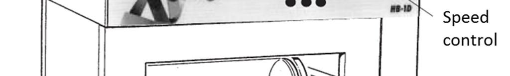
20 20 Front view of the HB-1D

21 SWITCHING ON OPERATION Once your HB-1D is connected to a power supply, switch it on using the power switch next to the power inlet socket on the rear panel. THE FRONT PANEL CONTROLS The front panel controls consist of a four digit LED temperature display, three buttons for controlling the display, three indicators and a speed control knob for adjusting the tube rotation speed. The front panel controls When you first switch on, the display will show the edition of the software installed on the unit. This will be displayed for 1 second then the actual temperature of the incubator will be indicated. SETTING THE SPEED Controller display Speed control knob 1. When turned fully anticlockwise, the speed control knob switches the rotation of the tubes off. 2. To increase the rotation speed, turn the knob clockwise until you reach the required speed. 3. Operation of the speed control knob increases the speed clockwise and decreases the speed anticlockwise in steps of approximately 4 rpm. 21
22 SETTING THE TEMPERATURE 1. To display the set temperature, press the SET temperature button: 2. To increase the set temperature, hold down the SET temperature button and press the Increase button. 3. To decrease the set temperature, hold down the SET temperature button and press the Decrease button. Each press of the Increase or Decrease buttons will increase or decrease the set temperature by 0.1 C. If the buttons are held down the temperature change will accelerate to 5 C per second. Note: It takes approximately 50 minutes for the interior of the hybridisation tubes to reach the displayed temperature depending upon the number of filters and amount of hybridisation fluid used. 22

23 INDICATORS 1. Power indicator. When lit, this shows that there is power to the unit. 2. Heater indicator. When this is lit or flashing, it indicates that the heater is heating the unit or controlling the temperature. If the oven is above the set temperature then the indicator will be off. 3. Over-temperature indicator. If this is lit, it indicates that the unit has developed a fault and the over-temperature cut-out has been triggered. This will cause the heater to be switched off and the unit will begin to cool even if the heater light is on. 23
24 HYBRIDISATION TUBES The hybridisation tubes are manufactured from durable thick borosilicate glass with a non-drip design. The tubes must be checked regularly and replaced if any damage occurs. Any damage to the ends of the tubes can cause them to break or leak when the end caps are inserted. Large (80mm diameter) tube assembly (FHB12) Remove the tube end cap which has the two holes in it. Place the filters in the tube and replace the end cap. A small quantity of Techne O-ring grease (part code , supplied with the HB-1D) must be smeared on the seal to facilitate the insertion of the end caps. Remove the spindle cap and add the fluids appropriate to the protocol through the hole in the spindle using a syringe. Replace the spindle cap and press it onto the spindle so that it clicks into place. Note: the tube will not rotate properly if the cap is not fitted securely. FHB12 assembly Small (44mm diameter) tube assembly (FHB32) Unscrew the tube end cap. Place the filters in the tube and replace the end cap. Remove the spindle cap and add the fluids appropriate to the protocol through the hole in the spindle using a syringe. Replace the spindle cap and press it onto the spindle so that it clicks into place. FHB32 assembly 24
25 Mini (4 x 32mm) tube assembly (FHB41 and FHB43) The mini tubes must be used in the FHB43 multi-tube holder. Unscrew the end cap of the tube. Place the filters and the liquids appropriate to the protocol in the tube and replace the end cap. Fix the tube into a multi-tube holder, using the springs, and ensure that there are four tubes in the holder. The end caps must be as shown, on alternate ends. The multi-tube holder will not rotate properly if there are not four mini tubes in it. 4 x FHB41 and FHB43 assembly 16 x 15ml tube assembly (F15ML1TH) and 8 x 50ml tube assembly (F50ML1TH) These tube holders are designed to hold 15ml and 50ml Falcon-type tubes. Unscrew the end cap from the tube. Place the filters and the liquids appropriate to the protocol in the tube and replace the end cap. Assemble the tubes into the multi-tube holder using the spring clips to hold them in place. The multi-tube holder will not rotate properly if it is not balanced properly. The multi-tube holder should be filled completely or at least balanced even if all the tubes are not being used. F15ML1TH assembly 25
26 INSTALLING THE HYBRIDISATION TUBES 1. Pre-heat the oven to the required temperature. 2. Insert the tubes or tube holder into the HB-1D ensuring that they rotate freely and the end caps engage on the drive rollers on the right had side of the chamber. 3. Close the door. 4. Turn the speed control knob until you reach the required speed. BASIC PROTOCOL FOR SOUTHERN HYBRIDISATIONS Insertion of filters Place a wet or moist filter, DNA side facing inwards, into a hybridisation tube and roll the tube, allowing the filter to adhere to the glass. Large trapped air bubbles should be smoothed out with a glass pipette; smaller air bubbles are acceptable and do not interfere with hybridisation so long as the surface of the filter is covered with hybridisation fluid. Several filters may be placed in one tube; there is a slight loss of signal, but no increase in background in the lower filters. To improve the signal we recommend the use of separation membranes between filters, part number FMEM2020. Pre-hybridisation Add 5 or 10ml of hybridisation fluid, according to the number of filters and the size of tube, so that the filters are covered. Allow to pre-hybridise for the required period. Hybridisation Drain off the pre-hybridisation fluid by removing the spindle cap from the fill and drain hole in the blue end cap and inverting the tube. Add the hybridisation liquid together with the radioactive probe using a syringe and needle through the fill and drain hole and replace the spindle cap. The minimum volume for a single filter is 5ml (when using large tubes). Allow to hybridise for the required period. Washes Drain off the hybridisation fluid through the fill and drain hole, collecting the probe in a suitable container for re-use or disposal. Washing depends on the stringency required and usually involves a series of washes with SSC buffer and SDS of decreasing concentration until background radiation has been removed. Notes: All radioactive waste can be collected for disposal; none need be disposed of down the sink. Radioactive probes can be collected and reused several times. As the protocols for this unit usually involve the use of radioactive materials the appropriate manufacturer's safety precautions must be taken into consideration. WARNING THE UNIT WORKS UP TO 100 C. This temperature can cause burns. Bibby Scientific Ltd. takes great efforts to protect operators from hazards, but the following points are brought to your attention: 1. Use care and wear protective gloves to remove hybridisation tubes from the cabinet if the unit is at high temperature. If the protocol allows, it is better to switch off the unit and open the door to allow the unit to cool to below 40 C before attempting to remove the tubes. 2. The coloured end cap of the 80mm large tube and the 44mm small tube has two holes. Take care not to spill radioactive probe through these holes. One hole allows the air to expand when the tube is heated. The other is the fill and drain hole which is revealed when the spindle cap is removed. 26
27 DO NOT TIP THE TUBE SO THAT THE COLOURED END IS DOWN AS THIS WILL CAUSE A SPILLAGE. 3. The unit has been designed to conform to international safety specifications and is fitted with a resettable over-temperature cut-out. If, for any reason, the temperature rises above a safe level for the instrument, the over temperature protection cuts out the heater, but the tubes continue to rotate. Check the reason for the cut-out; if there is no obvious cause, reset the cut-out once the unit has cooled. The reset, on the rear of the unit, is operated by pressing the centre of the button indicated on page 19. USER MAINTENANCE O ring seals on the FHB16 hybridisation tubes The O ring seals on the large 80mm diameter hybridisation tubes must be checked regularly and replaced before a leak occurs. Each tube is provided with 6 spare O rings and further O rings can be obtained from Bibby Scientific Ltd. or your Techne dealer. Hybridisation tubes The hybridisation tubes must be checked regularly and replaced if any damage occurs. Any damage to the ends of the tubes can cause them to leak or break when the end caps are inserted. Further tubes can be obtained from Bibby Scientific Ltd. or your Techne dealer. Cleaning your HB-1D Before cleaning your unit ALWAYS disconnect from the power supply and allow to cool. You can clean the case of the HB-1D with a cloth dampened in soapy water. No part of the unit should be immersed in solvents. Do not use acetone or abrasive cleaners. DO NOT USE ETHANOL OR METHYLATED SPIRITS ON THE ACRYLIC DOOR; these may make the acrylic go cloudy. Before using any cleaning or decontamination method except those recommended in this manual, the responsible body should check with Bibby Scientific Ltd. that the proposed method will not damage the equipment. If you spill the fluid Because of the nature of operation of the HB-1D, the complete inside must be cleaned if a spillage does occur. This is to remove any airborne particles which may have been blown around the system and to guarantee full operator safety. Switch the HB-1D off and disconnect it from the power supply. Follow this sequence of operations when the HB-1D has been allowed to cool below at least 50 C: Remove all glassware from the HB-1D. Remove the plastic drip tray. Clean all surfaces of the inner chamber using a suitable cleaning and decontaminating solution. Be careful of the drive shafts. Cleaning and decontamination materials recommended by Bibby Scientific include: Lipsol Decon 90 Neutracon Other mild detergent 27
28 ADDITIONAL INFORMATION Note that this equipment should only be dismantled by properly trained personnel. Removing the outer cover exposes potentially lethal mains voltages. There are no user serviceable parts within this equipment. FAULT FINDING Should you have any problems with your HB-1D which cannot be easily remedied, you should contact your supplier and return the unit if necessary. Contact the Bibby Scientific Ltd. Service Department (details given below) to obtain information on how to return the unit. Fill in the Decontamination Certificate provided with the unit and include the serial number and details of the fault observed. Please remember to return the unit in its original packing. Bibby Scientific Ltd. accepts no responsibility for damage to units which are not properly packed for shipping: if in doubt, contact your supplier, giving the full serial number of the unit. FUSES If the controller fails to light when power is supplied to the unit the fuses may have blown. Check that there is no external cause such as a faulty plug; check both fuses and replace any faulty fuse with one of the correct value. Fuse values are given on the label next to the mains input socket. SAFETY OVER-TEMPERATURE CUT-OUT The over-temperature cut-out is a sensitive mechanical device and mechanical shock can cause it to trip. In the event of no heater power, check the mains plug and lead, then reset the cut-out control by depressing the centre of the button. Repeated operation of the cut-out indicates a serious fault: you may need to return your unit to your supplier for repair. IF AN INCORRECT MESSAGE IS DISPLAYED If a message is displayed which shows an unexpected temperature or HELP, this may indicate a fault with the PRT (temperature sensor). This could indicate for example that a wire has broken; a wire or the connector to the PCB has become disconnected; or the PRT has been broken. You should contact the service department at Bibby Scientific Ltd. or your Techne dealer and return the unit if necessary. INSULATION TESTING This equipment is fitted with RFI suppression circuitry. Any check of the electrical insulation by means of high voltage dielectric testing (for example as in BS EN ) must be carried out using only a DC voltage. This unit contains semiconductor components which may be damaged by electric field effects. 28
29 SUPPORT CONTACTS If you require further technical or application assistance please contact Techne at: Phone: +44 (0) For servicing information please contact: Bibby Scientific Ltd. Service Department Beacon Road Stone Staffordshire ST15 0SA Phone: +44 (0) Please note that neither Bibby Scientific Ltd. nor any of their agents can accept the return of ANY GLASSWARE from these units. If the unit is returned it must be thoroughly decontaminated and a Decontamination Certificate returned with the unit. A copy of the certificate is available from our website, or can be requested from the Service Department if the unit is being returned. We are continually striving to improve our products and software. If you have any comments and suggestions on how we can do things better please send them to us at: technehelp@bibbyscientific.com. 29
30 SPARES AND ACCESSORIES The following spares and accessories may be purchased from Bibby Scientific Ltd. or their dealers. All Techne tubes are made from durable Borosilicate glass. Contact Bibby Scientific Ltd. or your Techne dealer for further details. Part code FHB12 FHB11 Description Large (80mm diameter) hybridisation tube assembly complete with sealing rings and end caps. Large (80mm diameter) glass tube only End cap (fill and drain) for large tubes, includes spindle cap (no sealing ring) End cap (blank) for large tubes (no sealing ring) Spindle cap (for use with and ) Sealing ring for large tubes (for 70 C operation) Sealing ring for large tubes (for >70 C operation) Techne O-ring grease (100g tube) FHB32 FHB31 Small (44mm diameter) hybridization tube assembly complete with sealing ring and end cap. Small (44mm diameter) glass tube only End cap (fill and drain) for small tubes, includes spindle cap (no sealing ring) Sealing ring for small tubes FHB41 4 x 32mm diameter mini tubes /1 Mini tube, glass tube only Cap for use with the mini tube Seal for use with the mini tube FHB43 F15ML1TH F50ML1TH FHB1/PLAT FHBSH1 FHTRACK Multi-tube holder for use with FHB41 (holds 4 mini tubes) 16 x 15ml tube assembly (holds 15ml Falcon-type disposable tubes) 8 x 50ml tube assembly (holds 50ml Falcon-type disposable tubes) Rocking platform Stainless steel mesh shelf Tube rack/holder (holds 3 large and 3 small tubes) FMEM2020 Membrane separators 20 x 20cm (pack of 5) Drip tray HH179(S) HH180(S) FCABLEUS UK mains lead with plug, 230V European mains lead with plug, 230V US mains lead with plug, 120V 30
31 DECLARATION OF CONFORMITY 31
Hybrigene Hybridisation oven
 Hybrigene Hybridisation oven OPERATOR S MANUAL Issue 7 07/2014 2 CONTENTS INTRODUCTION... 5 BEFORE USE... 6 Unpacking...6 SAFETY AND INSTALLATION... 7 Warning...7 Operator Safety...7 Installation...7 Environmental
DB100/2, DB100/3, DB100/4, DB100/2TC, DB200/2, DB200/3
 DB100/2, DB100/3, DB100/4, DB100/2TC, DB200/2, DB200/3 Dri-Block Heaters OPERATOR S MANUAL Issue 7 06/2014 Part code: 6106451 2 CONTENTS INTRODUCTION... 5 BEFORE USE... 6 Unpacking...6 SAFETY AND INSTALLATION...
Instruction Manual / Version 10. Dri-Block Heater DB100/2, DB100/3, DB100/4, DB100/2TC, DB200/2 and DB200/3
 Instruction Manual 6106451 / Version 10 Dri-Block Heater DB100/2, DB100/3, DB100/4, DB100/2TC, DB200/2 and DB200/3 DB100/2, DB100/3, DB100/4, DB100/2TC, DB200/2, DB200/3 CONTENTS PAGE INTRODUCTION 5 BEFORE
BL o CKICE OPERATOR'S MANUAL. Issue 1 9/09
 BL o CKICE OPERATOR'S MANUAL Issue 1 9/09 CONTENTS PAGE INTRODUCTION 2 BEFORE USE 3 Unpacking 3 SAFETY AND INSTALLATION 4 SÉCURITÉ ET CONSIGNES D'INSTALLATION 6 SICHERHEITS- UND INSTALLATIONSINFORMATIONEN
N o Ice. operator's manual. Issue 1 6/09
 N o Ice operator's manual Issue 1 6/09 contents page Introduction 2 Before use 3 Unpacking 5 Safety and installation 4 Sécurité et consignes d'installation 6 Sicherheits- und Installationsinformationen
Water Bath SWB1 SWB2 SWB3 SWB1D SWB2D SWB3D. Instructions for use Version 2.0. water bath SWB2D. mains on on. press to set. set. off.
 Water Bath SWB1 SWB2 SWB3 SWB1D SWB2D SWB3D Instructions for use mains on on off press to set set load 39.9 0 40 C 20 60 80 100 C over temp water bath SWB2D Version 2.0 Water Baths SWB1, SWB1D, SWB2, SWB2D,
SBL-1, SBL-2, SBL-2D Fluidised Baths
 SBL-1, SBL-2, SBL-2D Fluidised Baths Operator s Manual Issue 22 7/15 Techne is a trademark Techne, 2003 Important supplementary safety information Introduction Techne fluidised baths are safe and effective
FB-08 Fluidised Bath. Operator s Manual
 FB-08 Fluidised Bath Operator s Manual Issue 13 7/15 Techne is a trademark Techne, 2003 Important supplementary safety information Introduction Techne fluidised baths are safe and effective equipment when
Recirculating Cooler SRC14
 Recirculating Cooler SRC14 Instructions for use Version 2.0 Tank cover Flow control valve 90 o Elbow Control panel Outlet nozzle Inlet nozzle Cooling coil Circulation tank Maintenance panel Drain with
FB-08C Fluidised Bath. Operator s Manual
 FB-08C Fluidised Bath Operator s Manual Issue 10 7/15 Techne is a trademark Techne, 2003 Important supplementary safety information Introduction Techne fluidised baths are safe and effective equipment
Hybrigene. Hybridiser. Operator s Manual
 Hybrigene Hybridiser Operator s Manual Issue 6. Date of issue: 3rd May 2005 Techne is a trademark Techne, 2003 CONTENTS Hybrigene Operator's Manual page SAFETY AND INSTALLATION English 4 Français 5 Deutsch
HB-1D. Hybridiser. Operator s Manual
 HB-1D Hybridiser Operator s Manual Issue 25 Date of issue: 3rd May 2005 Techne is a trademark Techne, 2003 CONTENTS HB-1D issue 20 onwards Operator's Manual page SAFETY AND INSTALLATION English 4 Français
DB-2D, DB-2DH, DB-3D DB-3DL, DB-4D, DB-2TC Dri-Block
 DB-2D, DB-2DH, DB-3D DB-3DL, DB-4D, DB-2TC Dri-Block operator s manual Issue 5 09/11 DB-2D, DB-2DH, DB-3D, DB-3DL, DB-4D and DB-2TC Operator s Manual Contents page SAFETY and INSTALLATION 2 English 2
TE-10A, TE-10D and TU-20D Thermoregulator Operator s Manual
 TE-10A, TE-10D and TU-20D Thermoregulator Operator s Manual Instructions for use Issue 17 04/16 TE-10A, TE-10D and TU-20D Operator s Manual Contents page SAFETY and INSTALLATION English 3 Français 6 Deutsch
Techne Dri-Block range. Premium products at affordable prices. Adjustable safety cut-out New countdown timer. 230V and 115V variants
 New 5-digit LED display Cool-touch surfaces Premium products at affordable prices New C and F units 230V and 115V variants Adjustable safety cut-out New countdown timer Twin control unit 2, 3 or 4 block
SPREMIAGRUMI MANUALE D USO E MANUTENZIONE
 I F D E SPREMIAGRUMI MANUALE D USO E MANUTENZIONE JUICER INSTrUcTION AND MAINTENANcE MANUAL PRESSE-AGRUMES MANUEL D'UTILISATION ENTSAFTER BEDIENUNGS- UND WArTUNGSANLEITUNG EXTRACTOR DE JUGOS MANUAL DE
Siemens Automation Products Siemens AG All rights reserved A5E AB, 08/2017 1
 SIMATIC IPC277E Product Information General notes ATEX/IECEx - Additional Instructions for use in Gas Explosive Atmospheres (only valid for specific MLFBs - marked with IECEx/ATEX symbol on the nameplate
Stopper Station Series Push Button Models SS2xx2, SS2xx5, SS2xx9
 Installation and Service Instructions Stopper Station Series Push Button Models SS2xx2, SS2xx5, SS2xx9 ADA Compliant NOTE For LTUL Models, Form C contacts on timer, Rated 30 VDC 3A, the enclosed timer
INSTALLATION INSTRUCTIONS
 RISK 0F FIRE AND ELECTRICAL SHOCK Contact, improper installation, or improper servicing MAY RESULT IN DEATH OR SERIOUS INJURY! Fixture must be installed by a qualified electrician only. Fixture is intended
RU-200,RU-500 FC-200 and FC-500 Refrigerated units USER S MANUAL
 RU-200,RU-500 FC-200 and FC-500 Refrigerated units USER S MANUAL Issue 10. Date of issue: 23rd July 2003 Techne is the trademark of Techne and Techne Inc. Techne, 2003 CONTENTS Refrigerated units User's
MICRO-KJELDAHL EQUIPMENT ( MM SERIES ) OPERATING AND SAFETY INSTRUCTIONS
 OPERATING AND SAFETY INSTRUCTIONS") MICRO-KJELDAHL EQUIPMENT ( MM SERIES ) OPERATING AND SAFETY INSTRUCTIONS MICRO-KJELDAHL EQUIPMENT ( MM SERIES ) OPERATING AND SAFETY INSTRUCTIONS CONTENTS PAGE 1 INTRODUCTION... 1 2 SAFETY INFORMATION...
MICRO-KJELDAHL EQUIPMENT ( MM SERIES ) OPERATING AND SAFETY INSTRUCTIONS MICRO-KJELDAHL EQUIPMENT ( MM SERIES ) OPERATING AND SAFETY INSTRUCTIONS CONTENTS PAGE 1 INTRODUCTION... 1 2 SAFETY INFORMATION...
FGT5 & FGT6 Gelation Timer. Instructions for use
 FGT5 & FGT6 Gelation Timer Instructions for use English CLAMPING BAR PADDLE CONNECTOR PADDLE 1. Introduction Thank you for purchasing this piece of Techne equipment. To get the best performance from the
Constant Temperature Waterbaths
 Constant Temperature Waterbaths Models: WB1110 WB1120 WB1130 WB1140 Installation and Operation Manual Table of Contents Introduction... 1 Safety Considerations... 2 Installation... 2 Start Up... 4 Operation
Safety Information BEFORE YOU BEGIN CAUTION: CAUTION: CAUTION: IMPORTANT Observe all governing codes. IMPORTANT Use this oven only
 Safety Information BEFORE YOU BEGIN Read these instructions completely and carefully. IMPORTANT Save these instructions for local inspector s use. IMPORTANT Observe all governing codes and ordinances.
INSTALLATION INSTRUCTIONS
 WHEN REPLACING PCB ASSEMBLIES, PLEASE WEAR AN ESD WRIST STRAP AND CONNECT IT TO ELECTRICAL GROUND RISK OF FIRE AND ELECTRICAL SHOCK Contact, improper installation, or improper servicing MAY RESULT IN DEATH
WINDSHEAR STORM and WINDSHEAR STORM DELUXE MODEL NO: 98778/98780
 TORNADO INDUSTRIES, LLC 333 CHARLES COURT WEST CHICAGO, IL 60185 (630)-818-1300 FAX (630)-818-1301 WWW.TORNADOVAC.COM Operations & Maintenance Manual For Commercial Use Only WINDSHEAR STORM and WINDSHEAR
200i User s information manual
 M2i-UM-1 WARNING: If the information in this manual is not followed exactly, a fire or explosion may result, causing property damage, personal injury or loss of life. Cast iron condensing boiler 200i User
OPERATING INSTRUCTIONS. EchoThermJ ANALOG MULTI-POSITION STIRRERS AND STIRRING HOT PLATES. Document Number HS15-01 Revised May 20, 2011
 OPERATING INSTRUCTIONS EchoThermJ ANALOG MULTI-POSITION STIRRERS AND STIRRING HOT PLATES Document Number HS15-01 Revised May 20, 2011 Torrey Pines Scientific, Inc. 2713 Loker Ave. West Carlsbad, CA 92010
User Manual. Glass Countertop Mechandiser Refrigerator. Single Door Model: 360GSM3HCB, 360GSM3HCW Pass-Through Model: 360GSM32HCB, 360GSM32HCW
 Glass Countertop Mechandiser Refrigerator Single Door Model: 360GSM3HCB, 360GSM3HCW Pass-Through Model: 360GSM32HCB, 360GSM32HCW 12/2017 Please read the manual thoroughly prior to equipment set-up, operation
Thermo-Sealer. Manual Heat Sealer. User Manual
 Thermo-Sealer Manual Heat Sealer User Manual Thermo-Sealer Contents Page Page Introduction 2 Safety 2 Declaration of conformity 3 Caution and safety signs in accordance with IEC 417 4 Unpacking 4 Technical
USER MANUAL. Read manual thoroughly prior to equipment set-up, operation or maintenance. Model Model
 USER MANUAL Read manual thoroughly prior to equipment set-up, operation or maintenance. Model 243009 Model 243010 NEXEL 1-Door Reach-in Freezer NEXEL 2-Door Reach-in Freezer For questions, please contact
Zweifarbdesigns Two-colour designs Designs bicolores Design bicromatici
 Bei Zweifarbdesigns kann jeweils eine Grundfarbe (am Rahmen hinten) mit einer farbe (am Rahmen vorne) kombiniert werden. UK For two-colour designs you can combine a base colour (on the rear frame) with
USER MANUAL. Read this manual thoroughly prior to equipment set-up, operation or maintenance. Model
 USER MANUAL Read this manual thoroughly prior to equipment set-up, operation or maintenance. Model 243006 NEXEL Merchandiser Refrigerator 2 Door, 53.1''W x 31.9''D x 84.4"H (with casters) For questions,
Dehumidifier Déhumidificateur Dehumidificador
 Dehumidifier Déhumidificateur Dehumidificador User Manual HDN455E/HDN655E Guide de l Utilisateur HDN455E/HDN655E Manual del Usuario HDN455E/HDN655E Before operating this dehumidifier, please read these
SST FOR THE AIR CONDITIONING SYSTEM
 SST FOR THE AIR CONDITIONING SYSTEM Page SST FOR THE AIR CONDITIONING SYSTEM... 2 NOTE: D To find out the compressor type, please refer to the manufacturer s label affixed to the compressor. D For CFC-12
AGA TOTAL CONTROL. Model No. - TC3
 AGA TOTAL CONTROL Model No. - TC3 Installation Guide REMEMBER: when replacing a part on this appliance, use only replacement parts that you can be assured conform to the safety and performance specification
PUREFIRE GAS BOILERS USER S INFORMATION MANUAL PB HEAT, LLC 131 S. CHURCH ST BALLY, PA WARNING MISE EN GARDE TO BE COMPLETED BY THE INSTALLER
 USER S INFORMATION MANUAL PUREFIRE GAS BOILERS TO THE INSTALLER:This manual is the property of the owner and must be affixed near the boiler for future reference. TO THE OWNER: This boiler should be inspected
PEDESTAL INSTALLATION INSTRUCTIONS INSTRUCTIONS D INSTALLATION DU PIÉDESTAL
 PEDESTAL INSTALLATION INSTRUCTIONS INSTRUCTIONS D INSTALLATION DU PIÉDESTAL Table of Contents PEDESTAL SAFETY... 1 INSTALLATION REQUIREMENTS... 2 Tools and Parts... 2 Location Requirements... 2 Before
USER S INFORMATION MANUAL PB HEAT, LLC 131 S. CHURCH ST BALLY, PA WARNING MISE EN GARDE TO BE COMPLETED BY THE INSTALLER.
 USER S INFORMATION MANUAL SERIES PBC COMBINATION GAS BOILERS TO THE INSTALLER:This manual is the property of the owner and must be affixed near the boiler for future reference. TO THE OWNER: This boiler
Aluminum Heating Mantles
 Aluminum Heating Mantles ON/OFF HOT User Guide Version 1.3 ON/OFF IEC power inlet socket Power supply switch (large-volume models). Power to either the lower part of the element or the upper and lower
FRULLATORE B210 BLENDER MIXEUR STANDMIXER BEDIENUNGS- UND WARTUNGSANLEITUNG BATIDORA MANUAL DE USO Y MANTENIMIENTO MANUALE D USO E MANUTENZIONE
 I F D E FRULLATORE MANUALE D USO E MANUTENZIONE BLENDER USE AND MAINTENANCE MANUAL MIXEUR MANUEL D'UTILISATION STANDMIXER BEDIENUNGS- UND WARTUNGSANLEITUNG BATIDORA MANUAL DE USO Y MANTENIMIENTO B210 2
Tank, Heater, and Control Operation Manual REV. E DATE: 04May2015
 Tank, Heater, and Control Operation Manual 25-710-804 REV. E DATE: 04May2015 Hanson Research Corporation 9810 Variel Avenue Chatsworth, CA 91311 USA (800) 821-8165 (818) 882-7266 FAX (818) 882-9470 www.hansonresearch.com
Instruction Manual Advanced Mini Block Heaters Advanced Mini Block Heater with Heated Lid
 Instruction Manual Advanced Mini Block Heaters Advanced Mini Block Heater with Heated Lid Table of Contents Package Contents.............. 1 Warranty.............. 1 Installation.............. 2 Maintenance
FES - Series Portable Electric Heaters
 FOSTORIA INDUSTRIES 114 Roscoe Fitz Road Gray, TN 37615 Phone: 800-495-4525 Fax: 419-435-0842 www.fostoriaindustries.com Division of TPI Corporation YES - Series Suspended Electric Heaters FES - Series
Hardware User s Manual
 Hardware User s Manual Behavioral chambers References: LE26M (76-0566) Version: 1.0 Panlab, s.l.u C/Energía, 112 08940 Cornellà de Ll.(Barcelona) Spain www.panlab.com International Calls: +34 934 750 697
Analog Melting Point Apparatus
 Analog Melting Point Apparatus User Guide Version 1.2 7. Turn off to begin cooling. A brass plug can be used if more rapid cooling is required. IEC power inlet socket (at rear) Magnifying lens Capillary
Hardware User s Manual
 Hardware User s Manual References: LE760 (76-0227), LE762 (76-0228) Version: V05/11/2014 Panlab, s.l.u C/Energía, 112 08940 Cornellà de Ll.(Barcelona) Spain www.panlab.com International Calls: +34 934
Lumination TM Volumetric Retrofit Kit
 GE Lighting Installation Guide Lumination TM Volumetric Retrofit Kit BEFORE YOU BEGIN Read these instructions completely and carefully. WARNING AVERTISSEMENT RISK OF FIRE OR ELECTRIC SHOCK Luminaire wiring
Operation & Care Instructions Save For Future Reference ABOUT THE MACHINE
 Operation & Care Instructions Save For Future Reference Model Euro 930 Hepa vac Dry Canister HEPA Vacuum Cleaner This product is a high performance dry canister vacuum for commercial/industrial use. All
Millo / Millo pro. Nr x000 / 1805-x000
 Millo / Millo pro Nr. 1804-x000 / 1805-x000 Renfert GmbH Industriegebiet 78247 Hilzingen / Germany Tel. +49 7731 8208-0 Fax +49 7731 8208-70 info@renfert.com www.renfert.com Made in Germany 0208 21-6543
Installation Instructions
 Installation Instructions 42" Island Vent Hood ZV1050 monogram.com 1 Safety Information BEFORE YOU BEGIN Read these instructions completely and carefully. Save these instructions for local inspector s
SAVE THESE INSTRUCTIONS FOR FUTURE REFERENCE
 ZR Series Commercial Specification Troffers with Emergency Driver Includes: ZR14, ZR22 and ZR24 IMPORTANT SAFEGUARDS When using electrical equipment, basic safety precautions should always be followed
Installation Instructions If you have questions, call 800-GE-CARES or visit our website at:
 Installation Instructions If you have questions, call 800-GE-CARES or visit our website at: www.monogram.com 30" Convection Built-In Ovens Models: ZET1038 ZET1058 Monogram. We bring good things to life.
Installation Instructions Gas Cooktops
 Installation Instructions Gas Cooktops Questions? Call us at 1.800.432.2737 or visit GEAppliances.com. In Canada, call 1.800.561.3344 or visit GEAppliances.ca. IN THE COMMONWEALTH OF MASSACHUSETTS WARNING
Installation Instructions PANOS 5.25
 WHEN REPLACING PCB ASSEMBLIES, PLEASE WEAR AN ESD WRIST STRAP AND CONNECT IT TO THE ELECTRICAL GROUND RISK OF FIRE AND ELECTRICAL SHOCK Contact, improper installation, or improper servicing MAY RESULT
73 Series Spectrophotometer. Accessory fitting and operation manual
 73 Series Spectrophotometer Accessory fitting and operation manual 061 672 Safety Please read this information carefully prior to installing or using this equipment. 1. The unit described in this manual
Installation Instructions
 Installation Instructions (Cat. No. 1794-OB16) 3 7 1 English 2 6 4 5 Module Installation This module mounts on a 1794 terminal base unit. 1. Rotate keyswitch (1) on terminal base unit (2) clockwise to
TTT Digital Incubator
 TTT Digital Incubator 135000 135000-2 Operating Instructions N2400342 Rev. 1 08/13 Table of Contents 1.0 Safety... 3 2.0 Intended Use of Product... 4 3.0 Installation... 4 3.1 Unpacking the Unit... 4 3.2
INSTALLATION INSTRUCTIONS
 WHEN REPLACING PCB ASSEMBLIES, PLEASE WEAR AN ESD WRIST STRAP AND CONNECT IT TO ELECTRICAL GROUND RISK OF FIRE AND ELECTRICAL SHOCK Contact, improper installation, or improper servicing MAY RESULT IN DEATH
GARAGE DOOR OPENER KIT
 GARAGE DOOR OPENER KIT P/N 2883417 APPLICATION All 2018 and newer Slingshot models with Garage Door Opener By Homelink Kit PN 2881814 BEFORE YOU BEGIN Read these instructions and check to be sure all parts
ProSet Nose Equipment for Avdel Breakstem Rivets
 In this table you will find the correct nose tip and jaw pusher for your ProSet tool to install Avdel breakstem rivets. For some Avdel rivets conversion kits or nose tips are needed and have to be ordered
Instruction Sheet. Important Note: Information that requires special emphasis. Note: Information that supplements points in the main text.
 Instruction Sheet 4500089 Converting the Surface Scatter 7 sc Turbidimeter to SS7 sc-hst Safety information Please read this entire document before unpacking, setting up, or operating this equipment. Pay
AB Parts. ControlNet Coax Tap. Installation Instructions. (Cat. Nos TPR, -TPS, -TPYR, -TPYS) What s in This Document
 What s in This Document") Installation Instructions ControlNet Coax Tap (Cat. Nos. 1786-TPR, -TPS, -TPYR, -TPYS) What s in This Document Use this document as a guide when installing a ControlNet coax tap. To: See Page: verify package
Installation Instructions ControlNet Coax Tap (Cat. Nos. 1786-TPR, -TPS, -TPYR, -TPYS) What s in This Document Use this document as a guide when installing a ControlNet coax tap. To: See Page: verify package
INSTALLATION INSTRUCTION In-Ground Color Changing
 SAFETY INSTRUCTION IMPORTANT: NEVER attempt any work without shutting off the electricity. Read all instructions before installing. System is intended for installation by a qualified electrician in accordance
GBX GAS BOILERS USER S INFORMATION MANUAL
 S-GBXUM-2 00-GBXUM GBX GAS BOILERS USER S INFORMATION MANUAL WARNING: If the information in this manual is not followed exactly, a fire or explosion may result causing property damage, personal injury
FRULLATORE PROFESSIONALE
 OUNCES 2 0 3 3 3 32 2 2 2 1 1 1 0, 0, 0,7 0, 0,5 1,1 1,0 0,9 1, I F D E FRULLATORE PROFESSIONALE MANUALE D USO E MANUTENZIONE COMMERCIAL BLENDER USE AND MAINTENANCE MANUAL MIXEUR PROFESSIONNEL MANUEL D'UTILISATION
Hardware User s Manual
 Hardware User s Manual Isolation box Behavioral chambers References: LE26 (76-0157) Publication: PB-MF-MAN-005-REV1.0 Panlab, s.l.u C/Energía, 112 08940 Cornellà de Ll.(Barcelona) Spain www.panlab.com
ASPEC Positive Pressure Manifold. User's Guide
 ASPEC Positive Pressure Manifold User's Guide This Page Is Intentionally Left Blank Gilson, Inc. All rights reserved. All product and/or company names are trademarks of their respective holders. Use of
Strand Lighting Emergency Transfer Cabinet
 Strand Lighting Emergency Transfer Cabinet Installation & Operations Manual 16-May-2007 Emergency Transfer Cabinet Page 1 of 25 Pages Strand Lighting Emergency Transfer Cabinets are a cost effective range
PANOS. Installation Instructions Square, 5.25 Round Flangeless, Downlight. The following installation instructions relate to the options below
 WHEN REPLACING PCB ASSEMBLIES, PLEASE WEAR AN ESD WRIST STRAP AND CONNECT IT TO ELECTRICAL GROUND RISK OF FIRE AND ELECTRICAL SHOCK Contact, improper installation, or improper servicing MAY RESULT IN DEATH
Stopper Station Series SS-2008 Push Button Pneumatic Timer Button
 Stopper Station Series SS-2008 Push Button Pneumatic Timer Button ADA for operation Pneumatic Timer Models SS-2008 Red SS-2108 Green SS-2208 Yellow SS-2308 White SS-2408 Blue ALL MODELS COME WITH A COLOR
MW Pince courant de fuite Leakage current Clampmeter. Notice d utilisation User s Manual M3950M00
 MW 3950 Pince courant de fuite Leakage current Clampmeter Notice d utilisation User s Manual M3950M00 Safety Information To ensure safe operation and service of the Tester, follow these instructions. Failure
ELECTRIC BUNSEN INSTRUCTION BOOK. BA6101, BA6101/C, BA6101x1, BA6101x3. Page 1 of 20 M6877 Issue 9.6
 ELECTRIC BUNSEN BA6101, BA6101/C, BA6101x1, BA6101x3. INSTRUCTION BOOK. Page 1 of 20 M6877 Issue 9.6 Please take your time to read this Instructions book in order to understand the safe and correct use
INSTALLATION INSTRUCTIONS
 INSTALLATION INSTRUCTIONS with Design Guide Double-Drawer Built-In Refrigerator Monogram.com Safety Information BEFORE YOU BEGIN Read these instructions completely and carefully. IMPORTANT Save these instructions
Instruction Manual Standard Dry Block Heaters Advanced Dry Block Heaters U L
 Instruction Manual Standard Dry Block Heaters Advanced Dry Block Heaters 1 U L Table of Contents Package Contents.............. 1 Warranty.............. 1 Installation.............. 2 Maintenance & Servicing..............
INSTALLATION INSTRUCTION In-Ground
 SAFETY INSTRUCTION IMPORTANT: NEVER attempt any work without shutting off the electricity. Read all instructions before installing. System is intended for installation by a qualified electrician in accordance
Instruction Manual CG-1999-V-10 CG-1999-V-10E Heating Magnetic Stirrer
 www.cglifesciences.com Phone: 1-800-843-1794 by VELP Scientifica Instruction Manual CG-1999-V-10 CG-1999-V-10E Heating Magnetic Stirrer General Information Before using the unit, please read the following
05/2014. Mod: E99/PLA2-N. Production code: BEFT908L
 05/2014 Mod: E99/PLA2-N Production code: BEFT908L BEFT908L E99/PLA2-N CATALOGO PARTI DI RICAMBIO CATALOGUE PIECES DETACHEES ERSATZTEILKATALOG SPARE PARTS CATALOGUE GAS ELETTRICO TOP CON ARMADIO GAZ ELECTRIQUE
OWNER S MANUAL MANUEL DU PROPRIETAIRE BETRIEBSANLEITUNG MANUALE DEL PROPRIETARIO MANUAL DEL PROPIETARIO MANUAL DO UTILIZADOR GEBRUIKSAANWIJZING
 SETTING OWNER S MANUAL MANUEL DU PROPRIETAIRE BETRIEBSANLEITUNG MANUALE DEL PROPRIETARIO MANUAL DEL PROPIETARIO MANUAL DO UTILIZADOR GEBRUIKSAANWIJZING REMOTE CONTROLLER FOR AIR CONDITIONER TELECOMMANDE
Boekel Microplate Incubator
 Boekel Microplate Incubator Model 260700 & 260700-2 Operating Instructions N2400024 Rev. 1 Table of Contents 1.0 Safety... 3 2.0 Product Information... 4 3.0 Assembly... 4 3.1 Unpacking the Unit... 4 3.2
SERIES PSCII GAS BOILERS
 USER S INFORMATION MANUAL SERIES PSCII GAS BOILERS TO THE INSTALLER:This manual is the property of the owner and must be affixed near the boiler for future reference. TO THE OWNER: This boiler should be
Dry Bath Heating Systems
 Dry Bath Heating Systems Instruction Manual N2400-4001 Dry Bath Heating System, Single Block, Digital N2400-4002 Dry Bath Heating System, Dual Block, Digital www.starlabgroup.com DECLARATION OF CONFORMITY
Performance Thermal Binder
 Performance Thermal Binder TM Helios 60 E F S Please read these instructions before use. Lire ces instructions avant utilisation. Lea estas instrucciones antes de usar la máquina. INDEX LAMINATOR CONTROLS
SECURITY SYSTEM MANUALE D USO E MANUTENZIONE USE AND MAINTENANCE BOOK INSTRUCTIONS DE FONCIONNEMENT ET ENTRETIEN MANUAL DE USO Y MANTENIMIENTO
 SECURITY SYSTEM MANUALE D USO E MANUTENZIONE USE AND MAINTENANCE BOOK INSTRUCTIONS DE FONCIONNEMENT ET ENTRETIEN MANUAL DE USO Y MANTENIMIENTO ATTENZIONE: Gli operatori devono leggere e capire completamente
OPERATING INSTRUCTIONS INSTRUCTIONS DE FONCTIONNEMENT
 OPERATING INSTRUCTIONS INSTRUCTIONS DE FONCTIONNEMENT 7 0CAWBX 12 V 501273 Grey Road 1, Georgian Bluffs, Ontario N0H 2T0, Canada Toll Free: 1-800-567-3556 Phone: 519-534-1080 www.caframo.com Read and Save
USE. Steam dispensing. n 4 holes. How to access the programming function
 TURBOSTEAM SERIE M USE Steam dispensing Machines equipped with the TURBOSTEAM (STOP STEAM) dispensing system have the "stop steam dispensing when set temperature is reached" function, and can rapidly heat
INSTALLATION INSTRUCTIONS
 PANOS 3.5" Square and Round Downlight Flanged WHEN REPLACING PCB ASSEMBLIES, PLEASE WEAR AN ESD WRIST STRAP AND CONNECT IT TO ELECTRICAL GROUND RISK OF FIRE AND ELECTRICAL SHOCK Contact, improper installation,
QAA 142 Termination instructions Self-regulating trace heaters type ELSR-NA and -HA in Div1 with heater entry kit EL-HAZELECT Kit part No: 09CA051
 QAA 142 Termination instructions Self-regulating trace heaters type ELSR-NA and -HA in Div1 with heater entry kit EL-HAZELECT Kit part No: 09CA051 QAA 142 Instruction de terminaison pour des câbles chauffants
Tetra MAX. LED Lighting System. BEFORE YOU BEGIN Read these instructions completely and carefully. Installation Guide
 Tetra MAX LED Lighting System Installation Guide Volt GEMXRD-W, GEMXHRD-W, GEMXGL-W, GEMXBL-W, GEMXYG-W BEFORE YOU BEGIN Read these instructions completely and carefully. RISK OF ELECTRIC SHOCK Turn power
High-Efficiency Intelligent Hand Dryer
 SMARTdri High-Efficiency Intelligent Hand Dryer Secamanos inteligente altamente eficiente Intelligenter Hochleistungs-Händetrockner Sèche-mains intelligent à haute efficacité Asciugamani elettrico ad alta
Installation Instructions
 Design Guide with Installation Instructions Double-Drawer Built-In Refrigerator ZIDI240 ZIDS240 monogram.com Safety Information BEFORE YOU BEGIN: Read these instructions completely and carefully. IMPORTANT
Instruction Manual M6627 / Version 7.4. Slide Drying Bench MH6616 MH6616X1
 Instruction Manual M6627 / Version 7.4 Slide Drying Bench MH6616 MH6616X1 Please take your time to read this Instruction Manual in order to understand the safe and correct use of your new Electrothermal
Aquatron 4, 8, /95 Form Number Instructions For Use. Advance Models , , , ,
 Aquatron 4, 8, 11 Instructions For Use Advance Models 56250191, 56250192, 56250193, 56250205, 56250207 10/95 Form Number 56041318 TABLE OF CONTENTS Page Introduction...2 Parts and Service...2 Nameplate...2
Safety Information BEFORE YOU BEGIN CAUTION: CAUTION: CAUTION: CAUTION: IMPORTANT Observe all governing codes. IMPORTANT Use this oven only
 Safety Information BEFORE YOU BEGIN Read these instructions completely and carefully. IMPORTANT Save these instructions for local inspector s use. IMPORTANT Observe all governing codes and ordinances.
SOLA SM II Light Engine Instruction Manual
 SOLA SM II Light Engine Instruction Manual Lumencor, Inc. Document Number 52-10036 www.lumencor.com Emissions Certifications This equipment has been tested and found to comply with the limits of EMC directive
ChemScan mini Analyzer for Low Ammonia Monitoring Installation, Operation and Maintenance Manual
 ChemScan mini Analyzer for Low Ammonia Monitoring Installation, Operation and Maintenance Manual asaanalytics.com ChemScan mini Low Ammonia Analyzer O&M Manual - Rev 223K TABLE OF CONTENTS ANALYZER DESCRIPTION
Technical Manual for the Strobe - SM87 HXB
 Technical Manual for the Strobe - SM87 HXB Please note that every care has been taken to ensure the accuracy of our technical manual. We do not, however, accept responsibility for damage, loss or expense
MJ190-4 Aspirator Operator s Manual
 MJ190-4 Aspirator Operator s Manual anthony products, inc. Table of Contents Table of Contents/Warnings...1 Components...2 Aspirator Set-up... 3-4 Controls and Functions...5 Supplies...6 Troubleshooting...7
Illuminated Stopper Station Push Button
 Illuminated Stopper Station Push Button Model SS2xx6 Rely on STI Dimensions 4.880 in [123.95 mm] 3.218 in [81.74 mm] 1.625 in [41.28 mm].875 in [22.23 mm] Switch Rating 2 momentary independent Form C contacts,
Instruction Manual Round Top Hotplate-Stirrers. Advanced Unit
 Instruction Manual Round Top Hotplate-Stirrers Advanced Unit TABLE OF CONTENTS Package Contents............... 1 Warranty............... 1 Installation............... 2 Maintenance & Servicing...............