INSTRUCTION MANUAL. Iceman Portable Chiller System. Models Covered AC, AS, WC, and WS
|
|
|
- Margaret Nash
- 5 years ago
- Views:
Transcription


1 INSTRUCTION MANUAL Iceman Portable Chiller System Models Covered AC, AS, WC, and WS 2150 Elmwood Avenue - Buffalo, NY P# F# MOK3000E 11/17 i
2 Table of Contents Section 1 Warnings and Cautions Electrical Warning Evaporator Freeze-Up Caution Cold Weather Caution Overhead Piping Warning Reservoir Tank Overflow Connection Short Circuit Current Rating Caution Non Potable Water Capacity Derate... 2 Altitude Correction Factors... 2 High Ambient Temperatures... 2 Section 2 Installation Unpacking Location Warnings Electrical Connections Fluid Connections... 5 Process Fluid Connections (All Systems)... 5 Reservoir Tank Overflow Connection... 5 Condenser Cooling Water Connections Filling Reservoir Tank... 6 Section 3 Operation Initial Starting Procedure Shut Down Procedure Restarting Procedure Section 4 Maintenance and Service Preventative Maintenance Electrical Preventative Maintenance Pump/Motor and Mechanical Connections Preventative Maintenance Miscellaneous Preventative Maintenance Pump Maintenance Exploded View Drawing Seal Replacement/Maintenance Maintenance: Seal Replacement: Reassembly: Glossary of Indicators, Gauges, and Buttons Section 5 Eurotherm Controller (3000 Series) Operation MOK3000E 11/17 ii
3 Home List Navigation Keys Troubleshooting Alarm Indicators To Acknowledge an Alarm Remote Setpoint and Retransmission Scaling Section 6 Options Air Duct Flange (Top) Automatic Fill with Low Water Level Indication Crankcase Pressure Relief (CPR) Valve Digital Flow Meter Emergency Stop Overhead Piping Kit Process Purge Option (Air Connections) Valved Process Bypass Z Purge Instructions for Mokon Portable Chiller Systems Section 7 Troubleshooting Guide Process Loop Refrigeration Loop Section 8 Condensed Parts List Section 9 Warranty MOK3000E 11/17 iii
4 Portable Chiller and Full Range Systems Quick Start-Up Checklist Please verify that the product received matches the product ordered and that the equipment is designed for the intended application. The following quick checklist is an abridged version - always refer to the Mokon Manual provided for additional data and requirements prior to the commissioning of the unit. Electrical Inspection Verify amp draws and voltage on serial tag match electrical service being supplied. All electrical termination points checked for tightness. Electrical wiring completed and disconnect sized and installed per code and compliance. Motor rotation verified, motor(s) and compressor(s) bumped. Verify any remote control wiring is complete. Mechanical Inspection Mechanical fittings tight. Unions tight. Compression fittings tight. Insure Supply, Drain and Process connections are connected properly and operating pressure does not exceed ratings. Refrigeration Inspection Insure all refrigeration work has been completed by a certified refrigeration technician. Location and Good Standard Installation Practices Confirm safe access to equipment for maintenance, removal and lockout- tag out. Insure equipment is designed for the installed environment. Water-cooled condenser - Confirm water supply to condenser, if City water use 1.5 GPM/Ton, if Cooling Tower water use 3 GPM/Ton. Air-cooled condenser - Confirm there is no short-circuiting of exhaust air into intake of condenser. Allow a minimum of 4 feet (1.2 meters) on all four (4) sides to allow for proper ventilation of condenser. Unobstructed heights above systems vary from 5 feet (1.5 meters) to 20 feet (6 meters). See user s manual for recommendations. Please use extreme caution when dealing with hot surfaces. If systems are to be installed side by side where one system will be exhausting hot air on the next unit, they should be spaced apart a minimum of 15 feet (4.6 meters) for proper & efficient operation. Proper non-automotive glycol mixture is being used for selected temperature range under 50 F (10 C) Elmwood Avenue, Buffalo, NY Ph ; Fax MOKCLST7002 2/15
5 Section 1 Warnings and Cautions Please read and understand this manual before operating the system! 1.1 Electrical Warning The Mokon portable chiller system, as with all high voltage electrical equipment, should be connected according to all local and national codes. All installation, maintenance, service, repair, adjustment, and operation should be done only by qualified trained electrical personnel who have read and completely understood this instruction manual. To the upper right is a symbol for Electrical Danger. When it is seen on the following pages of this manual as well as on the system, care should be taken to avoid possible electric shock. All maintenance and service should be performed with the power isolated and locked out except where noted. 1.2 Evaporator Freeze-Up Caution Protect the evaporator on the Mokon portable chiller system from freeze-up. Evaporator temperatures are 10 F 15 F (-2 C to -9 C) lower than the coolant temperature shown on the thermostat or the temperature controller. Standard systems are set to operate between 50 F 65 F (10 C 18 C), but are engineered to operate as low as 20 F (-7 C). Unless your system was set to operate below 50 F (10 C) at the time of purchase, do not attempt to operate your Mokon portable chiller system below 50 F (10 C) without first contacting the Mokon customer service department. It will be necessary to derate the capacity of the system, change the default settings, and add glycol to the Mokon portable chiller system. Do not use automotive antifreeze in the Mokon portable chiller system due to waxy deposits that will form on the internal components at lower temperatures, reducing efficiency. Using automotive antifreeze will void your warranty! Only pure ethylene glycol/water mixture should be used. Mokon recommends that a food coloring die be added to signify that glycol is present in system. The glycol should have a corrosion inhibitor added to reduce the risks of metallic degradation. Note: The automatic fill option should not be used when system operating temperatures are below 50 F. The glycol in the reservoir tank will become diluted which will lead to system freezing. 1.3 Cold Weather Caution If the Mokon portable chiller system will be moved from your plant and will be subjected to freezing temperatures, the water in the system must be completely drained and/or sufficient antifreeze (not automotive antifreeze) added to prevent serious water damage from freezing. 1
6 1.4 Overhead Piping Warning When overhead piping is connected to a Mokon portable chiller system equipped with an open reservoir or non-pressurized expansion tank there is risk of overflow of the system s reservoir tank upon shutdown, this is due to the back flow of fluid volume from the overhead piping system. To prevent reservoir tank overflow an overhead piping kit should be installed. This kit is available from Mokon as an option. 1.5 Reservoir Tank Overflow Connection A reservoir tank overflow connection is supplied on all Mokon portable chiller systems with an automatic fill option. Should the automatic fill option malfunction the overflow connection will protect the system against an overflow condition. This connection is clearly labeled on the system and must be plumbed to a non-pressurized open drain connection. 1.6 Short Circuit Current Rating Caution Equipment supplied with a safety door disconnect or power cord is design rated for a short circuit current rating (SCCR) of 10,000 amperes RMS if protected with a class "J" fuse. 1.7 Non Potable Water This system has been designed for use in non-potable water applications only. For applications requiring potable water use please contact Mokon directly to discuss a product offering. 1.8 Capacity Derate Altitude Correction Factors Altitude (ft) 1,000 2,000 3,000 4,000 5,000 6,000 Factor High Ambient Temperatures The chiller efficiency will be reduced by up to 5% for every 5 over 90 F ambient. 2
7 Section 2 Installation 2.1 Unpacking Upon arrival inspection should be done to assure there was no damage during shipping. In addition, all electrical and mechanical connections should be inspected to ensure that they are secure and tight. This includes all electrical terminations, mechanical fitting union bulbs, compression fittings, etc. Note: Refer to Section 4.1 Preventative Maintenance. The maximum weights of the Mokon chiller systems when drained of water are:.5 hp 300 lbs (137kg) 10 hp 860 lbs (391kg) 1 hp 330 lbs (150kg) 15 hp 1650 lbs (749kg) 1.5 hp 425 lbs (193kg) 20 hp 1850 lbs (840kg) 2 hp 450 lbs (205kg) 25 hp 3700 lbs (1679kg) 3 hp 460 lbs (209 kg) 30 hp 3860 lbs (1751kg) 5 hp 565 lbs (257kg) 35 hp 4200 lbs (1906kg) 7.5 hp 840 lbs (382kg) 40 hp 4995 lbs (2266kg) Properly rated equipment should be used to move this machinery. When removing system from pallet, lift from bottom only. Care should be taken to ensure that the system will not tip. After removing from pallet, the system should only be placed on a level surface. 2.2 Location Mokon systems should be located in an area that provides adequate space for pedestrian and vehicle traffic. If this is not feasible, owner should provide additional safeguards including safety signs. For optimum system performance, allow adequate space and ventilation around entire system, as well as a means to direct vapors away from work area. There should be a minimum of four (4) feet of clearance around the entire Mokon system (all sides) for adequate ventilation and operation of the system. Recommended unobstructed heights above the system as follows: Up to 3 Ton Systems Ton Systems Ton and greater Systems 20 If multiple systems (air-cooled) are installed side by side a minimum of fifteen (15) feet of clearance is required between systems for proper operation. If braking casters are included, they must be in the locked position when system is in the operating position. Prior to moving, unlock the casters. Customer supplied and installed air vents (mechanical or electrical) should be placed at the highest point in the process for application where the process height is greater than eight (8) feet above Mokon system. 3
8 2.3 Warnings Owner should ensure by adequate supervision that correct safety, installation, maintenance and operating procedures described in this manual, as well as recognized industry practice, are followed by all personnel. All panels must be in place during normal operation. The top of the machinery should not be used for storage. Power sources or energy types referred to in this manual are water, glycol and electricity. This machinery is not for use in hazardous or explosion proof environments. Under normal operating conditions, the decibel level of the machinery is 80 db or lower from 5 away from the system. When operating the system, hearing protection is recommended. Any alteration, additions or modifications to any part of the system must receive prior written approval from Mokon s Engineering or Customer Service Departments. Refer to serial tag for motor and heater electrical information and schematic drawing number. 2.4 Electrical Connections Warning: The Mokon portable chiller system, as with all high voltage electrical equipment, should be connected according to all applicable state and local codes. All installation, maintenance, service, repair, adjustment, and operation should be done only by qualified trained electrical personnel who have read and completely understood this instruction manual. Before operating the Mokon portable chiller system, the grounding wire must be connected. The grounding wire is the green or green and yellow wire connected to the frame of the system. Connect ground wire to the ground screw (labeled PE) located in the electrical box Connect power lines L1, L2, L3, to disconnect switch or terminal blocks marked L1, L2, and L3 respectively, inside the electrical box. Overcurrent protection of the supply conductors should be sized according to The National Electrical Code (NEC) and any other applicable state and local codes. For Three Phase Systems: Connect the power cord leads inside the electrical box L1, L2, and L3 to terminals 2, 4, and 6 respectively on the safety disconnect switch located inside the electrical box. The customer supplied main electrical disconnect should be fused for the proper amp draw (see specifications on the serial tag). For Single Phase Systems: Connect the power cord leads inside the electrical box L1 and L3 to terminals 2 and 6 respectively on the safety disconnect switch located inside the electrical box. The customer supplied main electrical disconnect should be fused for the proper amp draw (see specifications on the serial tag). Note: For systems without an optional power cord, there is an entry hole in the electrical box for the customer-supplied power cord. Depending on the size of your power cord it may be necessary to enlarge this hole. 4
9 2.5 Fluid Connections Following are the fluid connections for the Mokon portable chiller system, both the water-cooled and the air-cooled version. Connect each port with full size, unrestricted, insulated hose or pipe. The hose or pipe should be equivalent in diameter to the port and rated for 100 PSI (689 kpa) and 100 F (38 C). Water Cooled Connection Size Tonnage Process Condenser : Fluid Connection/Port Sizes Process Fluid Connections (All Systems) Note: If the Mokon portable chiller system will feed a pulsating system such as a temperature control system, a bypass valve must be installed to ensure flow. There are two process fluid connections, To Process and From Process located on the back of the system. To Process: Connect this port to the process inlet, through which chilled fluid will enter the process. From Process: Connect this port to the process outlet, through which fluid will leave the process and return to the chiller. The fluid returning from the process must have a temperature of lower than 80 F (27 C). Note: Mokon recommends that you install a strainer on the from process line to prevent contamination from the process to enter the chiller. These strainers are available from the Mokon factory. Reservoir Tank Overflow Connection Air Cooled Tonnage Process Connection size A reservoir tank overflow connection is supplied on all systems with an automatic fill option. Should the automatic fill option malfunction the overflow connection will protect the system against an overflow condition. This connection clearly labeled on the system and must be plumbed to a nonpressurized open drain connection. 5
10 Condenser Cooling Water Connections (WC, WS Systems Only) Condenser cooling water may be obtained from city or tower water supplies. The water usage is dependent on the tonnage of the system and temperature of the water. Variation in the cooling water temperature will lead to variation in water usage. If city water is being used, it will need approximately 1.5 gpm (5.7 lpm) per ton of refrigeration. If tower water is being used, it will need approximately 3 gpm (11.3 lpm) per ton of refrigeration. Mokon recommends that you install a strainer on the condenser water supply line to eliminate any unnecessary fouling. The connections for the condenser cooling water are located in the back of the system, labeled Supply Water and Drain Water. Supply Water: Connect this port to an adequate source of cold, clean supply water. Do not restrict incoming water to the condenser. Drain Water: Connect this port to drain. Do not restrict outgoing water from the condenser. 2.6 Filling Reservoir Tank Isolate and lock out all power sources. Remove the top panel of the Mokon portable chiller system. Remove the lid to the reservoir tank. Fill the reservoir tank to a minimum of 3/4 full of water or water/glycol mixture. Use of glycol IS REQUIRED FOR OPERATION BELOW 45 F. The table on following page lists the correct glycol/water mixtures for operating at temperatures below 45 F. Warning: The use of ultra pure fluids (de-ionized, de-mineralized, etc.) in the standard Mokon systems is prohibited and will void the systems warranty. Please contact the Mokon factory for further recommendations. Warning: Use a pure ethylene glycol/water mixture with a corrosion inhibitor in the Mokon portable chiller system. Do not use automotive antifreeze! Automotive antifreeze will cause damage to the system, voiding your warranty and result in reduced efficiency. After the Mokon portable chiller system is operating and all lines to the process and within the chiller are full, maintain a minimum 3/4 full tank level. This will require the addition of more water or water/glycol to the tank after start up. The table below is for reference only. Water/Glycol Mixture Fluid Temperature from System % Glycol % Water 44 F to 32 F (7 C to 0 C) F to 25 F (-6 C to -4 C) F to 20 F (-4 C to -7 C) F to 0 F (-7 C to -18 C) F to -20 F (-18 C to -29 C) Note: Evaporator temperatures are 10 F 12 F (-12 C to -11 C) lower than process fluid temperatures. 6
11 NOTE: Standard systems are set to operate between 50 F 65 F (10 C 18 C), but are engineered to operate as low as 20 F (-7 C). Unless your system was set to operate below 50 F (10 C) at the time of purchase, do not attempt to operate your Mokon portable chiller system below 50 F (10 C) without first contacting the Mokon customer service department as a low temperature seal assembly will need to be installed to the supply pumpak & various items re-set for low temperature operation. It will be necessary to derate the capacity of the system, change the default settings, and add glycol to the Mokon portable chiller system. Note: Do not operate your chiller below 50F (10C) if system is equipped with an automatic fill option. The glycol will become diluted and your system will freeze. 7
12 Section 3 Operation The Mokon portable chiller system is a circulating fluid temperature control system, which is capable of providing chilled water of a water/glycol mixture to a process at lower temperatures than available from conventional water supplies. The system is designed for normal operating temperatures of 20 F to 65 F (-7 C to 18 C) unless otherwise noted. The Mokon portable chiller system is a system consisting of a refrigeration loop and water or water/glycol loop. The refrigerant loop circulates refrigerant through a variety of components, which causes the refrigerant to change phase from a gas to a liquid and then back to a gas. This produces a chilling action on the chilled water loop. The compressor takes the refrigerant from a low pressure, low temperature gas and compresses it to a high pressure, high temperature gas which flows to the condenser. The condenser changes the refrigerant from a gas to a liquid under high pressure. This flows through a filter dryer (to remove any dirt, debris, and moisture) then to a moisture indicator (to indicate any moisture problem) and then to a thermal expansion valve. The thermal expansion valve regulates the flow of high pressure liquid refrigerant into the evaporator, where the refrigerant changes from a high-pressure liquid to a low-pressure gas. The refrigerant absorbs heat from the water or water/glycol mixture in chilled fluid loop on the other side of the evaporator causing a phase change of the refrigerant, from a liquid to a gas. The refrigerant, as a lowpressure gas, returns to the compressor and the evaporator to dissipate it. The circulating fluid is pumped through the evaporator via a supply pump. As mentioned above, the refrigerant on the refrigerant loop absorbs heat from the water or water/glycol mixture and chills it. The water then flows to the process where it again picks up heat and returns to the evaporator to dissipate it. Due to the use of high-pressure refrigerant and to ensure proper operation of the system, several safety devices are standard on the Mokon portable chiller system. Only a qualified refrigeration technician should be allowed to service the system. 3.1 Initial Starting Procedure After all connections are made and the reservoir tank is filled as described in Section 2.6, the Mokon portable chiller system is ready to be started. Note: Regardless what type of heat-generating process your Mokon portable chiller system is used on, it is important that the Mokon portable chiller system is the first piece of equipment started. If you do not start the Mokon portable chiller system first, too much heat can accumulate and the system will not be able to catch up, appearing to be undersized for the application. For initial start-up it is recommended to turn on the main electrical disconnect for at least 12 hours before starting the Mokon portable chiller system. This will preheat the compressor oil and liquid refrigerant helping to protect the compressor. If the power has been disconnected more than 2 hours and less than 3 where the Mokon disconnect switch is in the off position, power to main electrical disconnect is recommended for at least 4 hours before starting the Mokon portable chiller system. This applies if the ambient air temperature is above 60F (15.5C), and the system is located indoors. If the system is not located indoors or the ambient air temperature is lower than 60F (15.5C), refer to the initial start-up instructions. If power disconnection to the compressor is longer than 3 hours refer back to initial start-up instructions above. 8
13 Ideally, it is recommended that power be applied to the system continuously except for service purposes. It is recommended that the crankcase heater should be checked for proper operation on a regular basis. Warning: During normal operation the compressor can get very hot which can cause burns. Do not touch the compressor or any of the refrigeration system piping during operation or if the system has been in operation. Remove both side panels for access to, and observation of, the system. For water-cooled condensing systems, turn on the water flow to supply water connections. (See Section 2.5 for Fluid Connections) Check the pump rotation using the following procedure (for 3 phase systems): o Turning on the supply pump momentarily; press the start button (the green light will illuminate) then the stop button (the green light will go off). o Check the rotation of the supply pump by viewing the motor armature through the louvers on the back of the motor as it slows down. The armature should be turning clockwise from the lead (rear) end. o If the rotation is incorrect, deactivate the power supply to the Mokon portable chiller system and switch any two power cord wires (L1, L2, L3) on the inlet of the disconnect switch. Restart the supply pump by pressing the start button (the green light will illuminate). The supply pump should provide positive pressure to the process. Allow the fluid to circulate for a few minutes to eliminate air pockets from the lines. This will decrease the possibility of cavitations. Turn on the compressor by pressing the start button (the green light will illuminate). o For Systems Equipped with a Scroll Compressor: Check the rotation of the compressor using the following procedure. Observe the high/low refrigeration gauges. Turn on the compressor by pressing the start button (the green light will illuminate). The high/low refrigeration gauges should rise/fall to proper levels (refer to the last step) Note: Phasing of the compressor is verified at the Mokon factory and should not be tampered with in anyway. If compressor phase verification is required contact the Mokon customer service department for instructions. Failure to do so will void your system s warranty. Warning: Do not run the scroll compressor in reverse direction. Check the refrigerant pressure for the proper reading. The high-pressure reading is PSI ( k Pa) for R-22/R-407C or PSI ( k Pa) for R- 134A dependent on load. The normal low-pressure readings are listed below in the table. If the pressures are other than these, CONSULT THE MOKON FACTORY. 9
14 Normal Low Pressure Gauge Readings Chilled Fluid Temperature Nominal Low Pressure Gauge Reading R-22/R-407C R-134A 60 F (16 C) 80 PSIG (552kPa) 45 PSIG (310kPa) 50 F (10 C) 65 PSIG (448kPa) 35 PSGI (241kPa) 45 F (7 C) 60 PSIG (414kPa) 30 PSIG (207kPa) 40 F (4 C) 55 PSIG (379kPa) 25 PSIG (172kPa) 30 F (-1 C) 30 PSIG (207kPa) 18 PSIG (124kPa) 20 F (-7 C) 30 PSIG (207kPa) 11 PSIG (76kPa) Set the controller or thermostat to the desired temperature. See Section 5 for complete controller directions for systems, which have a controller. Note: Automatic air purge, during start-up removes air from lines (add an air-bleed and/or air separator at highest process loop point if needed to help expel air from process). 3.2 Shut Down Procedure Note: The Mokon portable chiller system should be the last piece of equipment shut off to protect the system from overheating. Turn off the compressor by pressing the stop button (the green light will go off). Turn off the supply pump by pressing the stop button (the green light will go off). The main electrical power to the Mokon portable chiller system should remain connected. Note: When the power is turned off to the system, the compressor crank case heater is also turned off which will hamper the system s ability to burn off liquid in the compressor which will result in damage to the compressor. The main electrical power and the supply water (for water-cooled systems) to the Mokon portable chiller system may be turned off if the system is being relocated or for prolonged shut down. 3.3 Restarting Procedure If the water lines and main electrical power have not been disconnected, refer to Section 3.1. If the water lines and/or the main electrical power have been disconnected, refer to Section 2.4 for Electrical Connections, Section 2.5 for Fluid Connections, and Section 3.1 for Initial Start-Up Procedure. 10
.")

15 Section 4 Maintenance and Service Warning: The maintenance and service procedures included in Sections require that all power sources to the Mokon portable chiller system be shut off, isolated and locked out (exceptions noted). Follow all local and national codes and procedures for working on electrical equipment. Failure to do so could result in injury or death. Only qualified electrical personnel should install, maintain, repair, adjust, and operate Mokon portable chiller systems. The instruction manual furnished with the system should be completely read and understood before system maintenance. The following hazard warning symbols will be used to denote a specific hazard associated with a procedure. Electrical Danger High Temperature High Voltage & Surface May Be Hot Hot Surface 4.1 Preventative Maintenance Mokon portable chiller systems are designed for a long, trouble free service life under a variety of conditions, with a minimum of maintenance. Performing the following preventative procedures will extend the life of your system. Refer to Section in the instruction manual for specific adjustment or service procedures. Refer to the condensed parts list included in Section 8 of the instruction manual for proper replacement parts if required. The preventative maintenance section is broken into weekly, monthly, and every three months checks. Associated with each check is a series of corrective procedures that may solve a problem detected in the check. If the corrective procedures do not resolve a problem detected in the check, see the trouble shooting guide in Section 7 for a complete list of corrective measures. 11
16 Electrical Preventative Maintenance Weekly Checks Slightly tug on each conductor to make sure it makes a solid contact to its attached component. Pay close attention to the green grounding wires. Every 3 Months Checks Check that the interior electrical and mechanical components are securely fastened to the back panel, and/or to the sides of the electrical box Corrective Procedures Correct component wiring Verify voltage and frequency stamped on system matches customer supply voltage and frequency Correct excessive system load (current draw) Verify customer supply voltage is balanced and fluctuations are within 15% of nominal Verify wire gauge for main power hookup is properly sized Replace components if needed Tighten with proper tooling Corrective Procedures Tighten with proper tooling Inspect/replace fuses Inspect/replace motor starter overloads 12
17 Pump/Motor and Mechanical Connections Preventative Maintenance Weekly Checks Check for foreign materials obstructing airflow in the motor and pump area Monthly Checks Check that all bolts and screws are securely tightened Corrective Procedures Remove all dust, lint, grease or oil with a cloth and/or brush Corrective Procedures Tighten with proper tooling Repair solder joints Replace necessary parts if leaks persist Semi Annual Check The system s internal and external hoses and clamps should be inspected Correct motor wiring Verify supply voltage is balanced and fluctuations are within 15% of nominal Tighten with proper tooling Contact Mokon customer service or a qualified refrigeration technician Replace necessary parts if leaks persist Corrective Procedures Tighten with proper tooling Tighten with proper tooling Contact Mokon customer service or a qualified refrigeration technician Replace necessary parts if leaks persist Miscellaneous Preventative Maintenance Monthly Checks Corrective Procedures Check that all applicable lights, gauges, and indicators are functioning properly (Power On) Check that the "Warning," "High Voltage," "Caution," and lamicoid labeling are adhering to the correct locations Check the condenser coil (air-cooled systems) is free of dirt and debris Replace necessary parts Replace torn, damaged or missing labels Vacuum, blow clean, or chemically clean 13
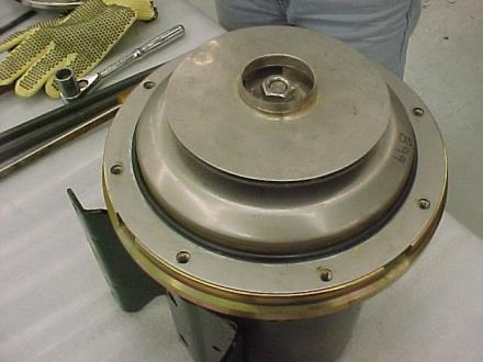
18 4.2 Pump Maintenance REF NO. Exploded View Drawing QTY ¾ HP HP HP HP HP DESCRIPTION PART # 1 CASE 1.25 x 1 NPT CASE 1.25 X 1 NPT CASE 1.5 x 1.25 NPT IMPELLER 4.88, STAINLESS IMPELLER 5.25, STAINLESS IMPELLER 6.3, STAINLESS IMPELLER 6.3, STAINLESS MOTOR 56J CONSULT FACTORY 11 1 COVER, STAINLESS * 1 NUT * 1 D-WASHER * 1 FLINGER DISC IRON * 1 GASKET, CASE * 1 SEAL, 5/8 IN REPAIR KIT * - DENOTES COMPONENTS INCLUDED IN REPAIR KIT

19 Seal Replacement/Maintenance Warning: Make certain that the system is disconnected from the power source in compliance with all local and national codes before attempting to service or remove any components. Never run the pump when dry. Maintenance: Inspection: Pump should be periodically checked for proper operation. If the system has changed or if the pump is operating noisily or erratically, then the pump should be removed and examined. It should be repaired and parts replaced as necessary. Cleaning: Remove oil, dust, dirt, water, chemicals from exterior of pump and motor. Blow out interior of open motors with clean compressed air at low pressure. Regularly drain moisture from TEFC motors. Draining: If the pump is located in an area subject to freezing temperatures, the pump must be drained when not in operation or add sufficient antifreeze. Disassembly: Seal Replacement: Turn off power. Drain the Mokon portable chiller system. Flush if necessary. Necessary Tools: o 3/8 drive ratchet o Pry bars (2) o Flat blade screwdriver o 6 socket extension 3/8 o Gloves o ¼ Hex Allen wrench/socket o ½ Socket 15


20 Remove pump/motor from cabinet. Remove casing screws and remove case. Inspect o-ring for wear or damage. Remove the cap at the lead end of the motor. A screwdriver slot will be exposed. Use a screwdriver to stop the shaft from turning. Caution: Do not insert screwdriver between impeller vanes to prevent rotation. This can damage the impeller. Remove the impeller lock nut and washers by turning counter clockwise when looking at the front of the pump. Remove the impeller by turning counter clockwise. Protect the hand by wearing a glove. Caution: Failure to remove the impeller in a counterclockwise direction may damage the threading on the impeller, the shaft or both. 16


 and the cardboard disc supplied")
21 Remove the spring to the mechanical seal assembly. With two pry bars 180 o apart and inserted between the seal housing and the motor plate adapter and carefully separate the two parts. The mechanical seal assembly will come off of the shaft inside the seal housing. It is not necessary to remove the cast iron disc from the motor. Using a dowel, push the mechanical seal assembly out of the seal housing from the motor side. Reassembly: Caution: The mechanical seal is a precision product and should be handled accordingly. Use care when handling lapped running surfaces of the mechanical seal to ensure they remain clean and are free of chips or scratches. Clean gasket and flange faces, seal seat cavity and shaft, in particular, shaft shoulder fitting against impeller. Lubricate the seal seat cavity of the cover and the rubber cup or O-ring of stationary seal seat with the lubricating fluid that comes with the mechanical seal or repair kit. Press the stationary seat in seal seat cavity in the cover squarely and evenly using an arbor press (if possible) and the cardboard disc supplied with the seal. Be certain that the lapped face (shiny side) is facing you. Place the seal assembly housing (with the seal assembly inserted) onto the shaft and replace the spring. Lubricating fluid can be applied to the motor shaft and the rubber bellows of the seal used to facilitate assembly. Do not contaminate the mechanical face seals with lubricant. Do not use petroleum based lubricants. 17


22 Thread the impeller onto the shaft by turning clockwise. Protect the hand with a glove. Prevent shaft rotation by using a screwdriver on the shaft end screwdriver slot. Replace the impeller lock nut and washer by turning clockwise. Prevent shaft rotation by using a screwdriver on the shaft end screwdriver slot. 18


23 Replace the casing and casing screws and tighten finger tight. Finish tightening the cap screws alternately and evenly to approximately 6 ft. lbs. torque. Note: It is imperative that screws be tightened alternately and evenly, as this action centers the cover in the casing, assuring proper alignment. Binding of the impeller in the case and adaptor may occur if the cap screws are not tightened as listed above. Check for free rotation then replace the cap at the rear of motor. Reinstall pump/motor into system. 19
24 4.3 Glossary of Indicators, Gauges, and Buttons Supply Pumps Start/Stop Buttons: Compressor Start/Stop Buttons: No Flow Indicating Light: Freezestat Indicating Light: Low Refrigerant Pressure Indicating Light: High Refrigerant Pressure Indicating Light: Supply Pump Pressure Gauge: Return Temperature Gauge: High Refrigerant Pressure Gauge: Low Refrigerant Pressure Gauge: Pilot light illuminates green to supply pump (chilled water circuit) to process is activated. Pilot light illuminates green to indicate refrigeration loop and compressor pump is activated. When illuminated indicates inadequate fluid flow returning to the Iceman system to ensure safe operation. When illuminated, indicates compressor has shut down due to coolant temperatures below safe operation. When illuminated, indicates compressor has shut down due to low refrigerant pressure. When illuminated, indicates compressor has shut down due to high refrigerant pressure. Indicates fluid pressure for the chilled water loop going to the process. Indicates the temperature of chilled water loop returning from the process. Indicates the pressure of the refrigerant, as it is being condensed in the condenser. This pressure is critical to the performance of the chiller and is generated by the compressor. The normal pressure is between PSIG/ kpa (R-22/R-407C) or PSIG/ kpa (R-134A) (depending on load). Indicates compressor suction pressure and is related to temperature setting and the adequacy of refrigerant charge. 20
25 Section 5 Eurotherm Controller (3000 Series) 5.1 Operation This section of the manual contains all essential information needed to operate the controller. Contact Mokon Customer Service with controller problems as well as warranty and repair issues. The controller is configured by model number. Inputs, outputs and alarm types are preset. Final setup and configuration are done from the keypad. The controller has four basic modes: Operator 1, Operator 2, Operator 3 and the configuration mode. The controller s default level is Operator 1, and is used for day to day operation. Note: Operator 2, 3 and configuration are password protected. Home List Navigation To step through list levels press and hold the Page button until level 1 is obtained. Press the up button or the down button to change levels. To step through parameters within a particular list, press the Scroll button until the required parameter is obtained. To change the value (or state) of a parameter, press the Up button or the Down button. *Refer to Section 5.1 Keys for button locations and descriptions. Levels Operator 1 Parameter Mnemonic Scroll Function WRK.OP WORKING OUPUT The Output % active output value SP1 SETPOINT SP2 SETPOINT A1.High ALARM 1 SETPOINT A2.Low ALARM 2 SETPOINT * A3.xxx ALARM 3 SETPOINT *Optional ID Customer ID Controller Revision # 21

26 Keys Note: Pictured is the 3216 Eurotherm controller - this also applies to 3204 and 3208 series controllers. Button or Indicator Name OP1 Output 1 OP2 Output 2 Page button Scroll button Down button Up button Explanation When lit, it indicates that alarm output is on. FREEZE PROTECTION will scroll. When lit, it indicates that alarm output is on. HIGH FLUID TEMPERATURE will scroll. Press to select a new list of parameters. Press to select a new parameter in a list. Press to decrease a value in the setpoint. Press to increase a value in the setpoint. ALM Alarm Flashes when in alarm condition. ALARM MESSAGE will scroll. OP4 Output 4 When lit indicates that the cooling output is on. COOLING will scroll. 22
27 5.2 Troubleshooting Diagnostic Alarms: E.ConF Display Shows What it means What to do about it A change made to a parameter takes a finite time to be entered. If the power to the controller is turned off before the change has been entered then this alarm will occur. Enter configuration mode then return to the required operating mode. It may be necessary to re-enter the parameter change since it will not have been entered in the previous configuration. Do not turn the power off to the controller while ConF is flashing. E.CAL Calibration error Re-instate Factory calibration E2.Er EEPROM error Return to factory for repair EEEr Non-vol memory error Note the error and contact your supplier E.Lin Invalid input type. This refers to custom linearization which may not have been applied corrector or may have been corrupted. Go to the INPUT list in configuration level and set a valid thermocouple or input type. Note: Some error messages may not appear, depending on the controller options. 5.3 Alarm Indicators ALM beacon flashing red = a new alarm (unacknowledged). This is accompanied by a scrolling alarm message. A typical default message will show the source of the alarm followed by the type of alarm. For example, FREEZE PROTECTION and HIGH FLUID TEMPERATURE. If more than one alarm is present further messages are flashed in turn in the main display. The alarm indication will continue while the alarm condition is present and is not acknowledged. ALM beacon on continuously = alarm has been acknowledged. 23
28 To Acknowledge an Alarm Press and together. Non-Latched Alarms Alarm condition present when the alarm is acknowledged. ALM beacon on continuously. The alarm message(s) will continue to scroll. This state will continue for as long as the alarm condition remains. When the alarm condition disappears all indication also disappears. If the alarm condition disappears before it is acknowledged the alarm reset immediately. 5.4 Remote Setpoint and Retransmission Scaling Scaling of the 4-20mA and 0-10V signals for this option are as follows: 4mA or 0V = minimum system operating temperature. 20mA or 5V, 10V = maximum system operating temperature. Note: Maximum system operating temperature value is reflective of the series system purchased, (refer to serial tag for maximum operating temperature located on Mokon system). Consult customer service at Mokon factory (716) , regarding system s minimum and maximum temperatures if there are any questions. 24
29 6.1 Air Duct Flange (Top) Section 6 Options This option allows the user to run duct work with a blower fan to the top of the air-cooled unit to draw the heat generated by the cooling process out of the room (area) where the chiller is located. The flange, placed by Mokon, will be sized per the unit. The customer will need to provide and install the accompanying duct work as well as the blower fan. The blower fan must be sized so that it delivers 1,000 cfm (minimum) per chiller ton of air flow for the proper ventilation (heat removal) of the chiller. Anything less will result in the chiller overheating and will shut down the unit. 6.2 Automatic Fill with Low Water Level Indication As stated in Section 2.6, the reservoir tank must maintain a minimum of ¾ total fluid capacity. This option provides for automatic monitoring and filling of the reservoir. Connect a constant supply water source to the ½ NPT tank connection at the back of the unit and leave on. When the level gets below the ¾ minimum, the Low Level light on the front of the electrical panel will come on and the unit, via a float switch, will fill to the required level. The light will then turn off. Keep in mind, use of glycol IS REQUIRED FOR OPERATION BELOW 45 o F AND MUST BE MANUALLY ADDED TO THE TANK. The table in Section 2.6 lists the correct glycol/water mixtures for operating at temperatures below 45 o F. 6.3 Crankcase Pressure Relief (CPR) Valve The chiller generally operates with a set point anywhere between 50 F (10 C) and 65 F (18.3 C) allowing for a return fluid temperature of up to 75 F (23.9 C). If it is desired to run the chiller temperature set point above 65 F (18.3 C) then a CPR valve is required. This regulating valve helps to maintain the proper suction pressure of the crankcase of the compressor so as not to overload the compressor motor. Even with the CPR valve, the maximum allowable temperature set point on a chiller is 85 F (29.4 C) with an assumed return fluid temperature of 95 F (35 C). At no time should the return fluid temperature to the chiller ever exceed 95 F (35 C)! This CPR valve is factory set and must never be adjusted by the customer!! 6.4 Digital Flow Meter This optional feature provides for a Blancett 1100 Series Turbine Flow Meter with flow indication on the TO Process line of each zone. See the CD for the flow meter Data Sheet and Manual. 6.5 Emergency Stop The emergency stop device will shut the machine down regardless of the operating mode. Once the emergency stop device has been activated, it must be disengaged by turning the button clockwise. Disengaging the emergency stop will not restart the machinery but only permit restarting. Per the risk assessment of the machine, the emergency stop is not wired to a safety rated relay. Do not wire additional safety components to the Mokon stop relay or modification of the emergency stop circuit is prohibited. 25
30 6.6 Overhead Piping Kit This option is required when the process and/or process piping is above the level of the unit and the volume is such that the total amount of fluid (water/water & glycol) used exceeds the capacity of the unit reservoir. Upon unit shut-down, the swing check valve(s) and the spring check valve(s) within the unit will prevent backflow of fluid from the process loop into the unit reservoir thereby avoiding an overflow condition. 6.7 Process Purge Option (Air Connections) To facilitate mold changes with a minimum amount of oil loss from the hoses and the process, a process purge system via air is provided as an option. Note: If additional fluid has been added to the Mokon system after initial start up, it will be necessary to drain the excess fluid prior to using the process purge as to avoid overflowing the reservoir tank. The following is the procedure to utilize this process purge option: Turn the controller to the minimum setting and wait until the process temperature is below 130F. (See Section 5 for Controller Instructions) Shut off the zone by pressing the Stop button. Connect the Air Supply to the Air Inlet on the system. Warning: Air supply pressure should not exceed 15 PSIG (103 kpa). Depress the Process Purge button on the control panel. The fluid in the process loop will be returned to the reservoir. Repeat steps 1 4 for each system. Refer to Section 3.1 to Restart the System. Note: The time required to purge the system is based on the holdup volume of the process and the air supply to the system. 6.8 Valved Process Bypass This option is simply a direct fluid path between the TO process line and the FROM process line that will allow you to bypass your process partially or completely via a metered globe valve on the outside back of the unit. This provides a means of controlling the amount of flow out to the process should you wish to reduce it from the normally full flow condition. 26
31 6.9 Z Purge Instructions for Mokon Portable Chiller Systems A 3 inch diameter threaded pipe connection is provided to receive an air or nitrogen supply, a 90 cfm blower is recommended. This blower shall not be installed or placed in the hazardous environment where hazardous fumes will be drawn from for supply air to the electrical enclosure or internal cabinetry of the Mokon system. The optimum nitrogen or air supply range to the Mokon system should be.15 to.5 inches of water column. As an alternative to nitrogen, non-hazardous clean dry air can be supplied which can also include clean dry compressed shop air. The discharge pressure of the fan or blower needs to be, at least, 3.0 inches of water column for every 100 equivalent feet of 3 duct. For 4 duct, 1.0 inch of water column per 100 feet is adequate. A 3 exhaust connection is also provided. Note: Due to temperature considerations, the purge gas must flow (sweep) through the unit to insure adequate ventilation. Once the purge gas is introduced, the Dwyer model F pressure switch will close, energizing a time delay relay. The relay prevents startup of the Mokon system until an adequate sweep inside the unit has taken place. The switch is set at its minimum setting of 0.15 inches of water. A green pilot light will illuminate once the relay has timed out, indicating it is safe to operate the unit. The magnehelic gauge has a scale of 0 to.5 inches of water, and is clearly visible to allow the operator to monitor the unit. If the purge is lost, for any reason, the pressure switch will open, thus activating a customer supplied alarm through a set of auxiliary contacts. The Mokon system will also shut off. For systems that are classified and applied properly the applicable Class, Group and Division is listed on the bottom of the systems serial tag. Methods: There are typically two methods for the supply of purge gas to systems for Z purge applications, they are as follows: Method # 1 (recommended): Due to temperature considerations, the purge gas must flow (sweep) through the unit to insure adequate ventilation. This method would apply to water, oil, chiller, and full range heater/chiller systems. Method # 2: (not recommended): Pressurization of the cabinetry when temperature build up is not as much of a concern can be applied. Here the exhaust coupling on the cabinet would be plugged. This method would apply to water-cooled chiller systems or very low heating capacity systems. Note: If the Z purge mechanism or any other system safety devices are modified or disable in any way Mokon considers them to be non-operational and the systems warranty could be void. 27
32 7.1 Process Loop Section 7 Troubleshooting Guide Problem Possible Cause Corrective Measure System unplugged / power off Improper power source wiring Blown fuse at power supply Blown control circuit fuse Low voltage Overload on pump/motor starter Inadequate flow of process fluid Flow switch Overload on pump/motor starter Blown fuse at power supply Blown control circuit fuse Faulty seal Improperly aligned seal Over-pressured seal Float switch Solenoid diaphragm will not seat Plug system in / turn power on Check wiring (electrical schematics) and correct Isolate open fuse and replace Replace and check for ground condition Measure incoming voltage, if too low correct Consult factory Inspect process and process lines for blockage; if blocked correct Inspect/replace component Consult factory Isolate open fuse and replace Replace and check for ground condition Inspect; if stuck, replace Inspect/replace 28
33 7.2 Refrigeration Loop Only a qualified refrigeration technician should attempt repairs in the refrigeration loop. Problem Possible Cause Corrective Measure Process fluid temperature below set point Scroll compressor rotating in the wrong direction Low or high refrigerant pressure Compressor shut down due to thermal protection Inadequate flow of process fluid Controller or thermostat (controller optional on 1/2 and 1 ton systems) Freezestat Blown control circuit fuse Low water flow through the condenser Water regulating valve Condenser supply water lines too small Insufficient water pressure drop across condenser due to plugged or fouled condenser tubes Condenser supply water temperature too high (above 85 o F / 29 o C) Dirty condenser coils Fan rotation High ambient air temperature Refrigeration loop overcharged Change set point Consult Mokon factory Consult a Qualified Refrigeration Technician Let cool, restart, and verify amp draw Inspect process and lines for blockage, clear blockage if necessary Consult factory (DO NOT attempt repairs, this will VOID your warranty!) Inspect/replace Replace and check for ground condition Verify condenser supply water flow rate is as stated in Section 2.5 Inspect/clean or replace Replace lines with insulated hose or pipe of equal diameter as the port Inspect/clean or replace Find colder source of water Inspect/clean Verify fan is rotating (counterclockwise) Blown control fuse Fan limit switch Consult Qualified Refrigeration Technician Find a cooler source or force more air Consult a Qualified Refrigeration Technician 29
Full Range Systems. Mokon Troubleshooting Guide Model 311. Process/Water Loop. Problem Possible Cause Corrective Measure. Process pump will not start
 Mokon Troubleshooting Guide Model 311 Process pump will not start Process pump shuts down during operation Pump seal leak Tank overflows or will not fill on systems with autofill option (water makeup valve)
CHILLER. Operator s & Installation Manual
 CHILLER MODELS: CH1001-A Operator s & Installation Manual Release Date: August 9, 2002 Publication Number: 620914301 Revision Date: May 6, 2010 Revision: E Visit the IMI Cornelius web site at www.cornelius.com
CHILLER. Model CH3000. Operator s & Installation Manual
 CHILLER Model CH3000 Operator s & Installation Manual Release Date: February 14, 2011 Publication Number: 620054173OPR Revision Date: May 08, 2014 Revision: B Visit the Cornelius web site at www.cornelius.com
INSTRUCTION MANUAL. Compact HTF Oil System. Models Covered H2 & H3
 INSTRUCTION MANUAL Compact HTF Oil System Models Covered H2 & H3 MOK2000E 12/17 2150 Elmwood Avenue - Buffalo, New York 14207 USA Telephone # 716-876-9951 Facsimile #716-874-8048 www.mokon.com Table of
HTD. High Temperature Non-Cycling Refrigerated Compressed Air Dryers. Operation & Maintenance Manual. MODELS HTD 21 thru HTD 100
 HTD High Temperature Non-Cycling Refrigerated Compressed Air Dryers Operation & Maintenance Manual MODELS HTD 21 thru HTD 100 - TABLE OF CONTENTS - 1.0 GENERAL 2 1.1 How to use this manual 1.2 Symbols
UNDERCOUNTER LABORATORY REFRIGERATORS and FREEZERS Installation, Operation and Maintenance Instructions
 UNDERCOUNTER LABORATORY REFRIGERATORS and FREEZERS Installation, Operation and Maintenance Instructions INSPECTION When the equipment is received, all items should be carefully checked against the bill
I.O.M. #075 11/05 INSTRUCTION MANUAL INSTALLATION OPERATION MAINTENANCE. with CF-1 Instrument
 I.O.M. #075 11/05 INSTRUCTION MANUAL INSTALLATION OPERATION MAINTENANCE with CF-1 Instrument TEMPTEK, INC. 525 East Stop 18 Road Greenwood, IN 46142 317-887-0729 fax: 317-881-1277 Service Department fax:
MDX. Non-Cycling Refrigerated Compressed Air Dryers with zero-loss Intellidrain Drain Trap. Operation & Maintenance Manual MDX MODELS 18 THRU 250
 MDX Non-Cycling Refrigerated Compressed Air Dryers with zero-loss Intellidrain Drain Trap Operation & Maintenance Manual MDX MODELS 18 THRU 250 TABLE OF CONTENTS HOW TO USE THIS MANUAL 2 SYMBOLS 2 WARRANTY
PDF Created with deskpdf PDF Writer - Trial ::
 Instruction Manual Index Introduction Uncrating and Checking for Damage Locating Your Unit Installation Fill Tank Process Connections Pre Startup Startup Sequence Trouble Shooting Chart Operating Lights
Installation, Operation and Maintenance Manual
 Installation, Operation and Maintenance Manual Packaged Chiller Models CC 6601, 6501, 6401, 6301, 6201, 6101 For Service, please contact Pfannenberg Service Company: U.S.A. Pfannenberg Inc. 68 Ward Road.
CH250 AND CH251 CHILLERS
 CH250 AND CH251 CHILLERS Operator s & Installation Manual Release Date: April 19, 2004 Publication Number: 620914801 Revision Date: May 15, 2015 Revision: G Visit the Cornelius web site at www.cornelius.com
CH750, CH751 & CH951 CHILLERS
 CH750, CH751 & CH951 CHILLERS Operator s & Installation Manual Release Date: April 19, 2002 Publication Number: 91256 Revision Date: March 25, 2014 Revision: F Visit the Cornelius web site at www.cornelius.com
Trouble Shooting Guide PWA, 3-phase (D10571)
") Trouble Shooting Guide PWA, 3-phase (D10571) Trouble Shooting Guide Problem Possible Cause Possible Remedy Unit does not start Unit does not cool No power to unit, breaker tripped Low voltage Loose wire
Trouble Shooting Guide PWA, 3-phase (D10571) Trouble Shooting Guide Problem Possible Cause Possible Remedy Unit does not start Unit does not cool No power to unit, breaker tripped Low voltage Loose wire
MDX. Non-Cycling Refrigerated Compressed Air Dryers with zero-loss Intellidrain. Operation & Maintenance Manual MODELS MDX
 MDX Non-Cycling Refrigerated Compressed Air Dryers with zero-loss Intellidrain Operation & Maintenance Manual MODELS MDX 800 1000 1200 TABLE OF CONTENTS HOW TO USE THIS MANUAL 2 SYMBOLS 2 WARRANTY 2 1.0
EQUIPMENT PRE-STARTUP AND STARTUP CHECKLIST TEL NO: ORDER NO: CONTRACT NO:
 Supersedes: (316) Form QTC4-CL2 (617) MODEL QTC4 EQUIPMENT PRE-STARTUP AND STARTUP CHECKLIST CUSTOMER: ADDRESS: PHONE: JOB NAME: LOCATION: CUSTOMER ORDER NO: TEL NO: ORDER NO: CONTRACT NO: CHILLER MODEL
MODEL YVAA EQUIPMENT PRE-STARTUP AND STARTUP CHECKLIST CUSTOMER: LOCATION: ADDRESS: CUSTOMER ORDER NO: PHONE: JCI CONTRACT NO: JOB NAME:
 Supersedes: 201.28-CL2 (817) Form 201.28-CL2 (1017) MODEL YVAA EQUIPMENT PRE-STARTUP AND STARTUP CHECKLIST CUSTOMER: LOCATION: ADDRESS: PHONE: JOB NAME: CUSTOMER ORDER NO: JCI CONTRACT NO: CHILLER MODEL
B. Unit construction shall comply with ASHRAE 15 Safety Code, NEC, and ASME applicable codes (U.S.A. codes).
.") Guide Specifications PART 1 GENERAL 1.01 SYSTEM DESCRIPTION Microprocessor controlled, air-cooled liquid chiller utilizing scroll compressors, low sound fans, hydronic pump system and optional fluid storage
Guide Specifications PART 1 GENERAL 1.01 SYSTEM DESCRIPTION Microprocessor controlled, air-cooled liquid chiller utilizing scroll compressors, low sound fans, hydronic pump system and optional fluid storage
! WARNING. McDonnell & Miller Installation & Maintenance Instructions MM-315(C)
") Models 51, 51-S and 53 Boiler Water Feeders Models 51-2, 51-S-2 and 53-2 Feeder Cut-Off Combinations McDonnell & Miller Installation & Maintenance Instructions MM-315(C) OPERATION Maximum Water Supply
Models 51, 51-S and 53 Boiler Water Feeders Models 51-2, 51-S-2 and 53-2 Feeder Cut-Off Combinations McDonnell & Miller Installation & Maintenance Instructions MM-315(C) OPERATION Maximum Water Supply
Surna 25-Ton Chiller Operating & Maintenance Manual
 www.surna.com 303.993.5271 Surna 25-Ton Chiller Operating & Maintenance Manual Models: 300F3-3. 300F4-3, 300FW-3 Revised: July 2015 Table of Contents Warranty Information 4 Limited Warranty 4 Limitation
Trouble Shooting Guide FAA, 3-phase (D3631)
") Trouble Shooting Guide FAA, 3-phase (D3631) Trouble Shooting Guide Problem Possible Cause Possible Remedy Unit does not start Unit does not cool No power to unit, breaker tripped Low voltage tripped Loose
Trouble Shooting Guide FAA, 3-phase (D3631) Trouble Shooting Guide Problem Possible Cause Possible Remedy Unit does not start Unit does not cool No power to unit, breaker tripped Low voltage tripped Loose
YCIV Hz & Hz
 YCIV 0590-1500 50Hz & 0157-0397 60Hz Start-up Checklist SERVICE POLICY & PROCEDURES Supersedes: Nothing Form 201.23-CL1 (309) Commissioning PREPARATION Commissioning of this unit should only be carried
INSTRUCTION MANUAL INSTALLATION OPERATION MAINTENANCE
 I.O.M. #058 1/03 INSTRUCTION MANUAL INSTALLATION OPERATION MAINTENANCE Covering Air-Cooled models from 5 to 30 tons with LE Instruments 525 East Stop 18 Road Greenwood, IN 46142 317-887-0729 fax: 317-881-1277
T-SERIES Air Conditioner. T20 Model INSTRUCTION MANUAL nvent Rev. C P/N
 T-SERIES Air Conditioner T20 Model INSTRUCTION MANUAL Rev. C P/N 89114993 TABLE OF CONTENTS Warranty and Return Policy... 2 IMPORTANT NOTICE... 2 RECEIVING THE AIR CONDITIONER... 3 HANDLING AND TESTING
INSTRUCTION MANUAL. HTF Oil System. Model# H44A24WD Elmwood Avenue - Buffalo, NY P# F#
 INSTRUCTION MANUAL HTF Oil System Model# H44A24WD 2150 Elmwood Avenue - Buffalo, NY 14207 P# 716-876-9951 - F#716-874-8048 - www.mokon.com Table of Contents Sections Page Section 1 Warnings and Cautions
LC Series - Light Commercial Pump Station Installation and Operation Manual
 LC Series - Light Commercial Pump Station Installation and Operation Manual Please keep this manual with the pump station Content Rain Bird LC Series Overview... Safety Instruction... Operation... 3 Pump
OPERATING AND MAINTENANCE MANUAL FOR PLATE HEAT EXCHANGER INDIRECT FIRED WATER HEATER. Electric Heater Company Base Model "BWXP"
 OPERATING AND MAINTENANCE MANUAL FOR PLATE HEAT EXCHANGER INDIRECT FIRED WATER HEATER Electric Heater Company Base Model "BWXP" HUBBELL ELECTRIC HEATER COMPANY P.O. BOX 288 STRATFORD, CT 06615 PHONE: (203)
SPECTRACOOL Air Conditioner. N21 Model INSTRUCTION MANUAL nvent Rev. G P/N
 SPECTRACOOL Air Conditioner N21 Model INSTRUCTION MANUAL Rev. G P/N 89115088 TABLE OF CONTENTS WARRANTY AND RETURN POLICY...2 RECEIVING THE AIR CONDITIONER...3 HANDLING AND TESTING THE AIR CONDITIONER...3
Operation Manual SCT14B and SCT18B. Inspection. 3 General Description. 3 General Requirements. 3 Standard Features.
 Spot Cooling Systems, Inc. 120 Century Drive Suite 00 Carrollton, TX 7006 00-6-776 Operation Manual SCT1B and SCT1B Warning! Improper installation, adjustment, alteration, service, or maintenance can cause
INSTALLATION AND OPERATING INSTRUCTIONS (2 Through 10-ton Air Cooled Single Stage Chillers)
") INSTALLATION AND OPERATING INSTRUCTIONS (2 Through 10-ton Air Cooled Single Stage Chillers) PORTABLE WATER CHILLERS COLD SHOT CHILLERS MARRONE & CO., INC. 14020 INTERDRIVE WEST HOUSTON, TEXAS 77032 TEL:
INSTALLATION AND OPERATING INSTRUCTIONS (2 Through 10-ton Air Cooled Single Stage Chillers) PORTABLE WATER CHILLERS COLD SHOT CHILLERS MARRONE & CO., INC. 14020 INTERDRIVE WEST HOUSTON, TEXAS 77032 TEL:
Series 47 and 247 Mechanical Water Feeders. Series 47-2 and Combination Mechanical Water Feeder/Low Water Cut-Off ! WARNING
 Series 47 and 247 Mechanical Water Feeders McDonnell & Miller Installation & Maintenance Instructions MM-316(C) Series 47-2 and 247-2 Combination Mechanical Water Feeder/Low Water Cut-Off Series 47 Water
INSTALLATION, OPERATION AND MAINTENANCE MANUAL FOR COMMERCIAL INDIRECT POWERED WATER HEATER
 INSTALLATION, OPERATION AND MAINTENANCE MANUAL FOR COMMERCIAL INDIRECT POWERED WATER HEATER ELECTRIC HEATER COMPANY BASE MODEL T Edition 0 HUBBELL ELECTRIC HEATER COMPANY P.O. BOX 88 STRATFORD, CT 0665
PROAIR Air Conditioner. CR23 Model INSTRUCTION MANUAL nvent Rev. D P/N
 PROAIR Air Conditioner CR23 Model INSTRUCTION MANUAL Rev. D P/N 89112522 TABLE OF CONTENTS Warranty and Return Policy...2 RECEIVING THE AIR CONDITIONER...3 HANDLING AND TESTING THE AIR CONDITIONER...3
Trouble Shooting Guide PAA, 1-phase (D3731)
") Trouble Shooting Guide PAA, 1-phase (D3731) Trouble Shooting Guide Problem Possible Cause Possible Remedy Unit does not start Unit does not cool No power to unit, breaker tripped Low voltage tripped Loose
Trouble Shooting Guide PAA, 1-phase (D3731) Trouble Shooting Guide Problem Possible Cause Possible Remedy Unit does not start Unit does not cool No power to unit, breaker tripped Low voltage tripped Loose
Trouble Shooting Guide RAA, 1-phase (D3627)
") Trouble Shooting Guide RAA, 1-phase (D3627) Trouble Shooting Guide Problem Possible Cause Possible Remedy Unit does not start Unit does not cool No power to unit, breaker tripped Low voltage tripped Loose
Trouble Shooting Guide RAA, 1-phase (D3627) Trouble Shooting Guide Problem Possible Cause Possible Remedy Unit does not start Unit does not cool No power to unit, breaker tripped Low voltage tripped Loose
INSTRUCTION MANUAL INSTALLATION OPERATION MAINTENANCE
 I.O.M. #058 1/03 INSTRUCTION MANUAL INSTALLATION OPERATION MAINTENANCE Covering Air-Cooled models from 5 to 30 tons with HE Instruments 525 East Stop 18 Road Greenwood, IN 46142 317-887-0729 fax: 317-881-1277
Table of Contents SPECIFICATIONS Page 2. FOR THE INSTALLER Page 3. FOR THE PLUMBER Page 4. INSTALLATION Page 5. INITIAL START UP Page 6
 INTRODUCTION This service manual covers the installation, operation, maintenance and service of this ice machine. Table of Contents SPECIFICATIONS Page 2 FOR THE INSTALLER Page 3 FOR THE PLUMBER Page 4
Covering Air-Cooled Models from 1 to 10 tons with M1 Chiller Control Instrument
 I.O.M. #090 7/10 INSTRUCTION MANUAL INSTALLATION OPERATION MAINTENANCE Covering Air-Cooled Models from 1 to 10 tons with M1 Chiller Control Instrument 525 East Stop 18 Road Greenwood, IN 46142 317-887-0729
Technical Data TYPE T14 & T14D TEMPERATURE PILOT SPENCE ENGINEERING COMPANY, INC. 150 COLDENHAM ROAD, WALDEN, NY SD 4511A T14 PILOT
 Technical Data SD 4511A SPENCE ENGINEERING COMPANY, INC. 150 COLDENHAM ROAD, WALDEN, NY 12586-2035 TYPE T14 & T14D TEMPERATURE PILOT PRINTED IN U.S.A. SD 4511A/9811 5 13 /16 D 4 7 /8 1 13 /16 T14 PILOT
WILKERSON MODELS DE3, DE4 AND DE5 COMPACT HEATLESS AIR DRYERS
 INSTRUCTION MANUAL FOR WILKERSON MODELS DE3, DE4 AND DE5 COMPACT HEATLESS AIR DRYERS DE3 - DE5 OPERATIONS GENERAL This instruction manual covers the installation, operation, maintenance and troubleshooting
Tornado Operations & Maintenance Manual
 TORNADO INDUSTRIES 7401 W. LAWRENCE AVENUE CHICAGO, IL 60706 (708) 867-5100 FAX (708) 867-6968 www.tornadovac.com Tornado Operations & Maintenance Manual MODEL NO. 99690 BD 22/14, 99720 BD 26/14 L9722
CHILLER MODEL: CH1500, 2000 AND 3000
 CHILLER MODEL: CH1500, 2000 AND 3000 Operator s & Installation Manual Release Date: February 12, 2010 Publication Number: 621055837OPR Revision Date: March 25, 2014 Revision: E Visit the Cornelius web
OK, OKA, OKAF; ELD; ELDM; ELH; OKC; SC; SCA; SCAF; OK-LN; OKA-LN; OKAF-LN.
 INSTALLATION, OPERATION & SERVICE MANUAL FOR COOLER TYPES OK, OKA, OKAF; ELD; ELDM; ELH; OKC; SC; SCA; SCAF; OK-LN; OKA-LN; OKAF-LN. 1. Introduction This manual is a guide for the installation, maintenance
HEATING AND VENTILATION
 SECTION 14-102.04 14-102.04/ 1 2007OC19 DESCRIPTION The heating, ventilation and air conditioning (HVAC) system is designed to optimize passenger comfort. The system regulates interior vehicle atmosphere,
Operation and Maintenance Haskris LX-Series, R-Series, WW-Series, OPC-Series
 Section 1: Temperature Control Your Haskris will have one of three different types of controller. Use table 1-1 to identify the relevant controller. The controller may appear different than examples. Contact
568X, 587X, 588X Series
 Please read and save this Repair Parts Manual. Read this manual and the General Operating Instructions carefully before attempting to assemble, install, operate or maintain the product described. Protect
1 ESMA, Inc. P. O. BOX 734 * SOUTH HOLLAND, IL * (800) * FAX (708)
 * FAX (708)") 1 2 Instructions for Ultrasonic Washer E789 (U.L. Approved) 1. INTRODUCTION The E789 Automatic Ultrasonic Washer automatically performs a cleaning cycle, the major steps of which are: Ultrasonic cleaning
1 2 Instructions for Ultrasonic Washer E789 (U.L. Approved) 1. INTRODUCTION The E789 Automatic Ultrasonic Washer automatically performs a cleaning cycle, the major steps of which are: Ultrasonic cleaning
SECTION air supply system + WARNING: + NOTE: GENERAL DESCRIPTION COMPRESSED AIR RESERVOIRS / 1.
 08-000.02/ 1 2011JA14 SECTION 08-000.02 GENERAL DESCRIPTION See Figure 1 for a schematic diagram of the. See the Nova LFS parts manual for a detailed schematic of the. The function of the vehicle s is
T-Series Air Conditioner T15 Model
 INSTRUCTION MANUAL T-Series Air Conditioner T15 Model Protecting Electronics. Exceeding Expectations. McLean Cooling Technology 11611 Business Park Blvd N Champlin, MN 55316 USA Tel 763-323-8200 Fax 763-576-3200
ICE CREAM TOPPING CABINETS REFRIGERATOR or FREEZER Installation, Operation and Maintenance Instructions
 ICE CREAM TOPPING CABINETS REFRIGERATOR or FREEZER Installation, Operation and Maintenance Instructions INSPECTION When the equipment is received, all items should be carefully checked against the bill
INSTRUCTION MANUAL DN0136 REVISION D
 INSTRUCTION MANUAL DN0136 REVISION D PIPING (Returns) Gravity return lines from system must be properly pitched down to unit inlet. Returns must also be trapped to prevent steam entry into the unit. An
Circulating Oil Temperature Control System
 Installation & Operation Manual Circulating Oil Temperature Control System i PQ451 161-123417-037 February 2019 Table of Contents Contents Page Number Section 1 Getting Started... 1 Section 2 Installation...
Patterson/AMT Inline Circulator Pump Refer to pump manual for General Operating and Safety Instructions.
 Please read and save this Repair Parts Manual. Read this manual and the General Operating Instructions carefully before attempting to assemble, install, operate or maintain the product described. Protect
Split Portable Air Conditioner
 SP-IOM-1 Please read and save this manual. Read carefully before attempting to assemble, install, operate or maintain the product described. Protect yourself and others by observing all safety information.
WMHP Series R410a Heat Pump INSTALLATION INSTRUCTIONS
 WMHP Series R410a Heat Pump INSTALLATION INSTRUCTIONS **WARNING TO INSTALLER, SERVICE PERSONNEL AND OWNER** Altering the product or replacing parts with non authorized factory parts voids all warranty
Standard and CELDEK Evaporative Cooler Modules Installation, Operation, and Maintenance Manual
 Standard and CELDEK Evaporative Cooler Modules Installation, Operation, and Maintenance Manual Standard Evaporative Cooler CELDEK Evaporative Cooler RECEIVING AND INSPECTION Upon receiving unit, check
489 & 490 Series CAST IRON UNITS BRONZE UNITS STAINLESS STEEL UNITS MAINTENANCE. Figure 1 - Mechanical Seal Replacement
 Please read and save this Repair Parts Manual. Read this manual and the General Operating Instructions carefully before attempting to assemble, install, operate or maintain the product described. Protect
Standard and CELDEK Evaporative Cooler Modules Installation, Operation, and Maintenance Manual
 Standard and CELDEK Evaporative Cooler Modules Installation, Operation, and Maintenance Manual Standard Evaporative Cooler CELDEK Evaporative Cooler RECEIVING AND INSPECTION Upon receiving unit, check
INSTALLATION, OPERATION & MAINTENANCE MANUAL BERG TEMPERATURE CONTROL UNIT
 INSTALLATION, OPERATION & MAINTENANCE MANUAL BERG TEMPERATURE CONTROL UNIT TABLE OF CONTENTS Description Page # Introduction 3 Customer Support 3 Model Number Nomenclature 4 Control Panel 5 Display Panel
OWNER S MANUAL. Vintage Classic HEAT COOL models. Proudly Made in the USA
 OWNER S MANUAL Vintage Classic HEAT COOL models Proudly Made in the USA support@aquacomfort.com www.aquacomfort.com/service-and-support 888-475-7443 Manufacturing High Quality, High Efficiency Heat Pump
OPERATIONS AND MAINTENANCE MANUAL FOR THE 8-TON TURF CART ENVIRONMENTAL CONTROL UNIT (ECU) PART NUMBER
 PART NUMBER") OPERATIONS AND MAINTENANCE MANUAL FOR THE 8-TON TURF CART ENVIRONMENTAL CONTROL UNIT (ECU) PART NUMBER 2001927 Prepared by: 860 Douglas Way PO Box 530 Natural Bridge Station, VA 24579 1 1.0 SCOPE: This
OPERATIONS AND MAINTENANCE MANUAL FOR THE 8-TON TURF CART ENVIRONMENTAL CONTROL UNIT (ECU) PART NUMBER 2001927 Prepared by: 860 Douglas Way PO Box 530 Natural Bridge Station, VA 24579 1 1.0 SCOPE: This
Liebert Small System MCD and PFH Condensers (1-5 Ton) Warranty Inspection Check Sheet
 Warranty Inspection Check Sheet") The following information must be fully completed and forwarded to your local Liebert sales office to establish your equipment warranty. Installer Address Owner Address Owner e-mail address Installation
The following information must be fully completed and forwarded to your local Liebert sales office to establish your equipment warranty. Installer Address Owner Address Owner e-mail address Installation
OWNERS GUIDE TO INSTALLATION AND OPERATION
 OWNERS GUIDE TO INSTALLATION AND OPERATION SPM SERIES HIGH POWER CENTRIFUGALS READ THESE INSTRUCTIONS CAREFULLY Read these installation instructions in detail before installing your pump. Be sure to check
INSTRUCTION MANUAL INSTALLATION OPERATION MAINTENANCE
 I.O.M. #083 /08 INSTRUCTION MANUAL INSTALLATION OPERATION MAINTENANCE Covers Models with VE Series Instrument. 525 East Stop 8 Road Greenwood, IN 4642 37-887-0729 fax: 37-88-277 Service Department fax:
HT650 TM FAN DRIVE SERVICE INSTRUCTIONS
 HT650 TM FAN DRIVE SERVICE INSTRUCTIONS When unpacking your product, remove all components and inspect them to ensure that no damage occurred during shipping. If any components are missing or damaged,
LABORATORY AIR COMPRESSORS AND VACUUM PUMPING SYSTEMS
 SECTION 22 20 00 LABORATORY AIR COMPRESSORS AND VACUUM PUMPING SYSTEMS PART 1 - GENERAL 1.1 RELATED DOCUMENTS: A. The Conditions of the Contract and applicable requirements of Division 1, "General Requirements",
GWC. User s Information Manual. Gas-Fired Water Boilers. Model
 Model GWC Gas-Fired Water Boilers User s Information Manual If the information in this manual is not followed exactly, a fire or explosion may result, causing property damage, personal injury or loss of
CHAMPION PUMP OWNER S MANUAL
 CHAMPION PUMP OWNER S MANUAL IMPORTANT SAFETY INSTRUCTIONS READ AND FOLLOW ALL INSTRUCTIONS SAVE THESE INSTRUCTIONS WARNING: Before installing this product, read and follow all warning notices and instructions
INSTRUCTION MANUAL INSTALLATION OPERATION MAINTENANCE
 I.O.M. #123 updated 03/28/2016 INSTRUCTION MANUAL INSTALLATION OPERATION MAINTENANCE Covering models From 5 to 40 tons With M1 Instruments & Scroll Compressors Model: Serial Number : 525 East Stop 18 Road
INSTALLATION AND OPERATING INSTRUCTIONS (2 Through 10-ton Air Cooled Single Stage Chillers)
") INSTALLATION AND OPERATING INSTRUCTIONS (2 Through 10-ton Air Cooled Single Stage Chillers) PORTABLE WATER CHILLERS COLD SHOT CHILLERS MARRONE & CO., INC. 14020 INTERDRIVE WEST HOUSTON, TEXAS 77032 TEL:
INSTALLATION AND OPERATING INSTRUCTIONS (2 Through 10-ton Air Cooled Single Stage Chillers) PORTABLE WATER CHILLERS COLD SHOT CHILLERS MARRONE & CO., INC. 14020 INTERDRIVE WEST HOUSTON, TEXAS 77032 TEL:
PROAIR Air Conditioner. CR43 Model INSTRUCTION MANUAL nvent Rev. H P/N
 PROAIR Air Conditioner CR43 Model INSTRUCTION MANUAL Rev. H P/N 10-1008-130 TABLE OF CONTENTS Warranty and Return Policy...2 RECEIVING THE AIR CONDITIONER...3 HANDLING AND TESTING THE AIR CONDITIONER...3
User s Information and Installation Instructions
 Outdoor Air Conditioner User s Information and Installation Instructions 10 SEER Standard Efficiency Split System These units have been designed and tested for capacity and efficiency in accordance with
PROAIR Air Conditioner. CR29 Model INSTRUCTION MANUAL nvent Rev. I P/N
 PROAIR Air Conditioner CR29 Model INSTRUCTION MANUAL Rev. I P/N 89104461 TABLE OF CONTENTS Warranty and Return Policy...2 RECEIVING THE AIR CONDITIONER...3 HANDLING AND TESTING THE AIR CONDITIONER...3
V SERIES HDR GAS RANGES
 SERVICE MANUAL ONE POWERFUL PACKAGE V SERIES HDR GAS RANGES TOPS Open Top Hot Top Griddle Top Work Surface BASES Standard Oven Convection Oven Cabinet Base - NOTICE - This manual is prepared for use by
569, 570, 571, 572 Series
 Please read and save this Repair Parts Manual. Read this manual and the General Operating Instructions carefully before attempting to assemble, install, operate or maintain the product described. Protect
Owner s Manual Refrigerated Compressed Air Dryers Model F-100
 Owner s Manual Refrigerated Compressed Air Dryers Model F-100 Read carefully before attempting to assemble, install, operate or maintain the product described. Protect yourself and others by observing
Elite Primer Baldor Series External Pond Pump
 Elite Primer Baldor Series External Pond Pump ( 5250PPB21, 6440PPB23, 7550PPB26, 9600PPB28) Installation and User s Guide IMPORTANT SAFETY INSTRUCTIONS, READ AND FOLLOW ALL INSTRUCTIONS. SAVE THESE INSTRUCTIONS
NON-CYCLING REFRIGERATED AIR/GAS DRYERS QPNC 75 to QPNC 250 OPERATOR S MANUAL
 NON-CYCLING REFRIGERATED AIR/GAS DRYERS QPNC 75 to QPNC 250 OPERATOR S MANUAL DATE OF PURCHASE: MODEL: SERIAL NO.: Record above information from nameplate. Retain this information for future reference.
REF. NO Clamp Assembly 8 1 set Gasket (4 per set) S.S. Lock-washer 3/8 x 1/ Brass Impeller 3.
 S.S. Lock-washer 3/8 x 1/ Brass Impeller 3.") 4.4 SUPPLY PUMPAK ASSEMBLY NOTE: This section applies only to systems, which include a supply pumpak. Only the H6, XA, and XC series systems contain a supply pumpak. If your system is a single zone, H6
4.4 SUPPLY PUMPAK ASSEMBLY NOTE: This section applies only to systems, which include a supply pumpak. Only the H6, XA, and XC series systems contain a supply pumpak. If your system is a single zone, H6
Fig. 1 - Unit PHD4 and WPH4
 OWNER S MANUAL 14 SEER Single -Package Heat Pump System with R -410A Refrigerant Single Phase and Three Phase 2 to 5 Nominal Tons PHD4 Series F and WPH4 Series B Fig. 1 - Unit PHD4 and WPH4 A09034 NOTE
STAINLESS STEEL UNITS
 Please read and save this Repair Parts Manual. Read this manual and the General Operating Instructions carefully before attempting to assemble, install, operate or maintain the product described. Protect
CIRRUS AIRPLANE MAINTENANCE MANUAL
 COOLING 1. DESCRIPTION On aircraft serials 183 and subsequent, an optional air condition system is available. This section contains the maintenance practices pertinent to this system. Cabin ventilation
HEATLESS DESICCANT AIR DRYER INSTRUCTION & MAINTENANCE MANUAL
 HEATLESS DESICCANT AIR DRYER INSTRUCTION & MAINTENANCE MANUAL H-Series & 203 THRU 223 SERIES ARROW PNEUMATICS, INC. REGENERATIVE DRYER DIVISION 2111 WEST 21ST STREET BROADVIEW, IL 60155 708-343-9595 708-343-1907
INSTALLATION INSTRUCTIONS TXV Horizontal Slab Coils WLSH
 TXV Horizontal Slab Coils WLSH These instructions must be read and understood completely before attempting installation. It is important that the Blower and Duct System be properly sized to allow the system
CROWN. Boiler Co. Santa-Fe Series. Hydronic Air Handlers INSTALLATION, OPERATION & MAINTENANCE INSTRUCTIONS
 CROWN Boiler Co Santa-Fe Series Hydronic Air Handlers INSTALLATION, OPERATION & MAINTENANCE INSTRUCTIONS These instructions must be affixed on or adjacent to the air handler Models: SAC049A20 SAC059A25
T-Series Air Conditioner T20 Model
 INSTRUCTION MANUAL T-Series Air Conditioner T20 Model Protecting Electronics. Exceeding Expectations. McLean Cooling Technology 11611 Business Park Blvd N Champlin, MN 55316 USA Tel 763-323-8200 Fax 763-576-3200
SMF PUMP OWNER S MANUAL
 SMF PUMP OWNER S MANUAL IMPORTANT SAFETY INSTRUCTIONS READ AND FOLLOW ALL INSTRUCTIONS SAVE THESE INSTRUCTIONS WARNING: Before installing this product, read and follow all warning notices and instructions
KG 092 SHOWN READ ALL INSTRUCTIONS IN THIS MANUAL AND RETAIN FOR FUTURE REFERENCE WARNING
 See unit nameplate for manufacturer and address. 507350-03 3/2016 Supersedes 9/2015 KG 024, 030, 036, 048, 060, 072, 074, 090 (2, 2-1/2, 3, 4, 5, 6 and 7-1/2 Tons) KG 092, 102, 120, 150 (7-1/2, 8 1/2,
CELDEK Evaporative Cooler Module Installation, Operation, and Maintenance Manual. CELDEK Evaporative Cooler
 CELDEK Evaporative Cooler Module Installation, Operation, and Maintenance Manual CELDEK Evaporative Cooler RECEIVING AND INSPECTION Upon receiving unit, check for any interior and exterior damage, and
ECONO FLO 2.7HP VARIABLE SPEED PUMP OWNER S MANUAL
 ECONO FLO 2.7HP VARIABLE SPEED PUMP OWNER S MANUAL IMPORTANT SAFETY INSTRUCTIONS READ AND FOLLOW ALL INSTRUCTIONS SAVE THESE INSTRUCTIONS WARNING: Before installing this product, read and follow all warning
CFF-500 CHILLER. Operator s & Installation Manual. Release Date: November 3, 1996 Publication Number: Revision Date: March 25, 2014 Revision: F
 CFF-500 CHILLER Operator s & Installation Manual Release Date: November 3, 1996 Publication Number: 90667 Revision Date: March 25, 2014 Revision: F Visit the Cornelius web site at www.cornelius.com for
WineZone Ceiling Mount Ductless Split 15
 WineZone Ceiling Mount Ductless Split 15 Requires an HVAC technician to install and charge with R-22 refrigerant. Easy to install. Unit plugs into wall outlet. Industrial grade unit for longer life. Indoor
CHILLER. Operator s & Installation Manual
 CHILLER MODEL: CFF-500 Operator s & Installation Manual Release Date: November 3, 1996 Publication Number: 90667 Revision Date: May 10, 2010 Revision: E Visit the IMI Cornelius web site at www.cornelius.com
AC6 & AC8 HORIZONTAL SERIES Sealed Metallic Centrifugal Pumps Installation and Maintenance Instructions
 AC6 & AC8 HORIZONTAL SERIES Sealed Metallic Centrifugal Pumps Installation and Maintenance Instructions ASSEMBLY PUMPS WITH MOTORS 1. No assembly required. Unpack the pump and motor and examine for any
Owner s Manual Refrigerated Compressed Air Dryers Models F-200, 250, 300 & F350
 Owner s Manual Refrigerated Compressed Air Dryers Models F-200, 250, 300 & F350 Read carefully before attempting to assemble, install, operate or maintain the product described. Protect yourself and others
1025, BOUL. MARCEL-LAURIN INSTRUCTION MANUAL FOR WATER COOLED ENVIROCHILL CHILLER. Prepared par Claude Gadoury, P. Eng MTL TECHNOLOGIES INC.
 WYETH-AYERST CANADA INC. 1025, BOUL. MARCEL-LAURIN S T - L A U R E N T, Q U É B E C INSTRUCTION MANUAL FOR WATER COOLED ENVIROCHILL CHILLER MODEL P448800LT--55WC--22C66S Prepared par Claude Gadoury, P.
CHILLERS. Operator s & Installation Manual
 CHILLERS MODELS: CH750, CH751 & CH951 Operator s & Installation Manual Release Date: April 19, 2002 Publication Number: 91256 Revision Date: May 5, 2010 Revision: D Visit the IMI Cornelius web site at
SELF-PRIMING CENTRIFUGAL PUMPS BMLS-M & BMLS-H
 SELF-PRIMING CENTRIFUGAL PUMPS BMLS-M & BMLS-H INSTALLATION, OPERATION & MAINTENANCE INSTRUCTIONS HP Phase Medium Head High Head 3 1 BMLS 300 M BMLS 300 H 3 3 BMLS 300 M3 BMLS 300 H3 5 1 BMLS 500 M BMLS
UNDERCOUNTER REFRIGERATORS AND FREEZERS Installation, Operation and Maintenance Instructions
 UNDERCOUNTER REFRIGERATORS AND FREEZERS Installation, Operation and Maintenance Instructions Please read this manual completely prior to installing and operating this equipment. This manual describes how
INSTALLATION INSTRUCTIONS GEO PRIME TANK. (Patent Pending) GPC
 GPC") INSTALLATION INSTRUCTIONS GEO PRIME TANK (Patent Pending) GPC Table of Contents General Description 2 Installation 3 Flushing and Purging 5 Initial Start up 7 Adding or Checking Fluid 8 Replacing a Pump
INSTALLATION INSTRUCTIONS GEO PRIME TANK (Patent Pending) GPC Table of Contents General Description 2 Installation 3 Flushing and Purging 5 Initial Start up 7 Adding or Checking Fluid 8 Replacing a Pump
ZG Shown READ ALL INSTRUCTIONS IN THIS MANUAL AND RETAIN FOR FUTURE REFERENCE WARNING
 See unit nameplate for manufacturer and address. 507258-04 7/2018 Supersedes 10/2017 ZG 036, 048, 060, 072, 074 (3, 4, 5 and 6 Tons) ZG 092, 102, 120, 150 (7-1/2, 8-1/2, 10 and 12 Tons) ROOFTOP UNITS ZG