WARNINGS. Nortek Global HVAC (UK) Limited, Fens Pool Avenue, Brierley Hill, Doc West No. Midlands, Page DY5 1QA 1 of 60. Part No.
|
|
|
- Patience Douglas
- 5 years ago
- Views:
Transcription

1 MIRD VISION VSO/VSXO RDINT TUE HETERS INSTLLTION ND OPERTING MNUL INDEX Section Introduction and Document Index Installation Requirements ssembly Instructions Commissioning Instructions Servicing Instructions Spare Parts Fault Finding Guide Replacing Parts User and Operating Instructions WRNINGS Nortek Global HVC (UK) Ltd equipment must be installed and maintained in accordance with the relevant provisions of the Gas Safety (Installations and Use) Regulations 1998 for gas fired products. Due account should also be taken of any obligations arising from the Health and Safety at Works ct 1974 or relevant codes of practice. In addition the installation must be carried out in accordance with the current IEE wiring regulations (S 7671), S 6896 (Industrial & Commercial) and any other relevant ritish Standards and Codes of Practice by a qualified installer. ll external wiring MUST comply with the current IEE wiring regulations. Part No Nortek Global HVC (UK) Limited, Fens Pool venue, rierley Hill, Doc West No. Midlands, Page DY5 1Q 1 of 60
2 Introduction. Welcome to the new range of high efficiency mbirad Vision radiant tube heaters. Local regulations may vary in the country of use and it is the installers responsibility to ensure that such regulations are satisfied. ll installation, assembly, commissioning and service procedures must be carried out by suitably qualified and competent persons to the statutory regulations in the country of use. When assembling, installing, commissioning and servicing is undertaken on radiant tube heaters specified in these instructions, due care and attention is required to ensure that working at height regulations are adhered to at the mounting heights specified. PLESE RED this document prior to installation to familiarise yourself with the components and tools you require at the various stages of assembly. ll Dimensions shown are in mm unless otherwise stated. The manufacturer reserves the right to alter specifications without prior notice. Document Index. 1 Installation Requirements 1.1 Health & Safety 1.2 Model Definitions 1.3 Heater Suspension 1.4 Wall Mounting 1.5 Herringbone Systems 1.6 Clearance to Combustibles 1.7 Gas Connection & Supply 1.8 Electrical Connections 1.9 Ventilation Requirements Unflued Radiant Heater Mechanical Ventilation Natural Ventilation Flued Radiant Heater Mechanical Ventilation Natural Ventilation 1.10 Flue & Combustion ir Inlet Options Important Information Flue Installation Condensation Considerations Flue/Tailpipe Connections 1.11 Technical Details 2 ssembly Instructions 2.1 Tools Required 2.2 ssembly Notes Tubes Turbulators rackets Couplers U end Reflectors End Caps urner ssembly Heat Exchanger ssembly H Damper ssembly Fan ssembly End Moulding Fixing H Manifold ssembly Detailed ssembly Drawings 3 Commissioning Instructions 3.1 Tools Required 3.2 alancing the Herringbone System 3.3 Commissioning chart 4 Servicing Instructions 4.1 Tools Required 4.2 urner Description 4.3 urner Removal 4.4 urner Gas Injector Servicing 4.5 urner Head and Electrode Servicing 4.6 Combustion Fan ssembly Unitary Heater 4.7 Combustion Fan ssembly Powered urner 4.8 Radiant Tube Servicing 4.9 Heat Exchanger Servicing 4.10 Reflector Servicing 4.11 Inspection of Flue 4.12 Re-commissioning after Service 5 Spare Parts 6 Fault Finding Guide 7 Replacing Parts 7.1 urner Controller Replacement 7.2 ir Pressure Switch Replacement 7.3 Gas Valve Replacement 8 User and Operating Instructions 8.1 To Start Heater 8.2 To Switch Off Heater 8.3 Routine Maintenance etween Service Intervals 8.4 Frequency of Servicing Doc No Page 2 of 60
3 1. Installation Requirements. Isolate any electrical supply to the heater and controller before proceeding. 1.1 Health and Safety mbirad heaters must be installed in accordance with the relevant provisions of the Gas Safety (Installations and Use) Regulations Due account should also be taken of any obligations arising from the Health and Safety at Works ct 1974 or relevant codes of practice. In addition the installation must be carried out in accordance with the current IEE wiring regulations (S 7671), S 6896 (Industrial & Commercial) and any other relevant ritish Standards and Codes of Practice by a qualified installer. Isolate all electrical supplies to the heater & controller before proceeding. For your own safety we recommend the use of safety boots and leather faced gloves when handling sharp or heavy items. The use of protective eye wear is also recommended. 1.2 Model Definitions VSOUT = mbirad Vision U Tube Unitary heater with painted induced burner, ID Fan, aluminised steel reflectors, end caps, insulation, tube over shields, painted canopies and optional end covers. VSOUH = mbirad Vision U Tube Herringbone heater with painted induced burner, Damper, aluminised steel reflectors, end caps, insulation, tube over shields, painted canopies and optional end covers. VSXO = mbirad Vision High efficiency U Tube heater with forced burner, recuperative heat exchanger, aluminised steel reflectors, end caps, insulation, tube over shields, painted canopies and optional end covers. 1.3 Heater Suspension The heater must be suspended by LL of the suspension brackets. See fig 1.b. ttachment to the heater support lugs should be made by a speed link, D shackle or in the case of drop rods, a closed formed hook. The hanging attachments to overhead steelwork etc. must be purpose made to good sound engineering practice or of a proprietary type fixing. They must be adequately fixed and designed to carry the whole weight of the heater. In the event of suitable roof steelwork being unavailable, additional steelwork should be fitted to enable vertical hangers to be used for suspending the heaters. If there are any doubts as to the strength or suitability of roof steelwork to which heaters are to be suspended, please refer to a Consultant, rchitect or owner of the building. The minimum mounting heights for mbirad heaters are given in the table below. MINIMUM Mounting Height (m) Model Inclined / wall Horizontal mounted Wall Mounting These radiant tube heaters can be wall mounted using the appropriate bracket (mbirad part no WM ). When using the wall mounting brackets the heater must be inclined at an angle between 30 and 35. Table 1 ngle Mounting Heater Size Required angle Chain length U Tube Eyebolt position links 1 Figure 1.a. ngle Mounting using the Wall mounting bracket 13. E Doc No Page 3 of 60
4 Figure 1.b. Recommended Methods of Heater Suspension. 15 max. Where chain supports have an angle of inclination greater than 15 an equal and opposite support is recommended. Vertical suspension chain ideal. Where supports are inclined, maximum recommended angle of inclination is 15. * * Vertical or inclined suspension on this plane is acceptable. These angles to be equal and not more than 45. ON U TUE VRINTS THE HETER SHOULD SLOPE DOWNWRDS TOWRDS THE RETURN END Y PPROX. 10mm FOR OTH HORIZONTL ND WLL MOUNTED INSTLLTIONS. Typical Speedlink attachment. Shackle method of attachment. Pin must be tightened by pliers. Drop rod with formed hook. note. hook or eyebolt must be closed tight. Doc No Page 4 of 60
5 1.5 Herringbone Systems (VSOUH). The manifold system should be arranged to fall slightly in the direction of the vacuum fan. This ensures that any condensation formed in the manifold on cold start and cool down is not trapped or allowed to drain back into the heater unit. This allows condensate to flow towards the condensate trap located at the vacuum fan end of the manifold system. (See figure 2a below for condensate trap arrangement). The manifold should be supported by chain, stainless steel flexible wire, or other flexible means from the roof structure to allow movement caused by thermal expansion. For 100mm diameter manifold the maximum distance between supports is 2.4m and 3.0m for 150mm diameter. Flexible couplers (supplied by mbirad) must be inserted within the manifold system to allow linear expansion to take place and prevent stress and strain on the system. The manifold must be supported either side of the flexible coupler. The exhaust flue should be adequately supported from the building structure and installed in accordance with the ritish Standard Code of Practice S 5440 Part 1 Installation and maintenance of flues and ventilation for gas appliances of rated input not exceeding 70kW net (1st, 2nd and 3rd family gases) condensate trap assembly must be provided at the end of the manifold system before the hot gas vacuum fan. U trap shall be 457mm deep. The end cap of the collecting chamber to be fitted with a flush flanged tank connector. ny protrusion to be removed leaving the inside flush with end cap. Figure 2b. Collecting Chamber rrangement The end cap should be sealed with silicon jointing compound and pop riveted in position. ll condensate drains from the flue collecting chamber to the disposal point shall be corrosion-resistant material of not less than 22mm internal diameter. Copper or copper based alloy shall not be used for condensation drains. See reference S Condensate drain pipes must be protected against the effects of freezing. The Type 0 and Type 2 vacuum fans have bottom horizontal discharge with rectangular connections (flanged on the type 0) and must be mounted in that position by means of the fan support stool onto a suitable platform or brackets fixed to the building structure. For details of the fan outlet fixing holes see below. Figure 2c. Type O Fan Outlet Dimensions Figure 2a. Condensate Trap rrangement Figure 2d. Type 2 Fan Outlet Dimensions The minimum depth of the condensate collecting chamber shall be 305mm and the minimum depth of the condensate drain pipe Doc No Page 5 of 60
6 For details of fan mounting bracket and fixing down holes see figure Figure 2g. Stainless Steel Telescopic Through The Wall rrangement (available for Type O and Type 2 fans) Figure 2e. Conventional Flue rrangement Roof Exit. Where a conventional flue is to be installed, mbirad supply an aluminium transformation piece to which a 150mm (6ins) diameter flue must be attached. The length of flue which may be connected to the fan outlet must be adequately supported from the building structure. Figure 2f. Conventional Flue rrangement Wall Exit. Figure 2h. Typical Low Fan rrangement Doc No Page 6 of 60
7 Figure 3. Vacuum Fan Mounting Details (Type O fan illustrated) Hole Centers Fig 2c/d Hole Centers Fan Type O Type C D E F G H J K L Power (watts) Running Current (amps) Starting Current (amps) Voltage 230V 1ph 230V 1ph Doc No Page 7 of 60
8 Figure 4. Typical Herringbone system (VSO shown with optional end covers) Dos and don'ts of herringbone system Dos Check design pressure drop. Don ts Run drains in copper or mild steel pipework. Check for corrosive industrial process in proposed building - e.g. cleaning, electroplating, printers using sugar powder etc. Drain all flue ducts and seal all joints. Secure joints with pop rivets as well as sealing compound (refer to assembly instructions). Fit drain traps before and after fans (see figs 4). Install system with extra 90 bends without asking mbirad if the system will operate correctly. Install flue with vertical rise without firstly fitting a drain point at it s lowest level. Fit fan with outlet vertical or with top horizontal discharge. Fit damper upside down or on it s side. Fit expansion joints before fan and at intermediate points on the herringbone system. Run drains in galvanised steel or plastic pipes. Fit damper wrong way round. (see fig18) Follow guide to combined flue heating system. Doc No Page 8 of 60
9 1.6 Clearance to Combustibles. The minimum clearances to combustible materials are given in the tables below. These minimum distances MUST be adhered to at all times. Figure 5.a Diagram illustrating the clearance to combustibles (VSXO shown c/w End Covers) F D C E DIM '' DIM 'C' DIM 'D' DIM 'C' VSXO 20/25 30/35/40 bove Canopy bove urner / Flued Heat Exchanger bove urner / Heater Outlet Unflued To the Sides C elow Tubes D From Heater Outlet (UNFLUED) E End Wall F / Doc No Page 9 of 60
10 Figure 5.b Clearance to combustibles Vision Optima Unitary VSO UT F D C DIM '' DIM 'C' DIM 'C' DIM 'C' VSO UT 15/20/25 30/35/40 bove Canopy bove urner / Flued Heat Exchanger bove urner / Heater Outlet Unflued To the Sides C elow Tubes D From Heater Outlet (UNFLUED) E End Wall F / Doc No Page 10 of 60
11 Figure 5.c Clearance to combustibles Vision Optima Herringbone VSO UH F D C DIM '' DIM 'C' DIM 'C' DIM 'C' VSO UH Herringbone 15/20/25 30/35/40 bove Canopy bove urner / Flued Heat Exchanger bove urner / Heater Outlet Unflued To the Sides C elow Tubes D From Heater Outlet (UNFLUED) E End Wall F / Doc No Page 11 of 60


12 1.7 Gas Connection and Supply efore installation, check that the local distribution conditions, nature of gas and pressure, and adjustment of the appliance are compatible. competent or qualified engineer is required to either install a new gas meter to the service pipe or to check that the existing meter is adequate to deal with the rate of gas supply required. Installation pipes should be fitted in accordance with S 6896, so that the supply pressure, as stated in Table 4 will be achieved. It is the responsibility of the competent engineer to ensure that other relevant Standards and Codes of Practice are complied with in the country of installation. Pipes of smaller size than the heater inlet gas connection must not be used. The complete installation must be tested for soundness as described in the country of installation. The gas union service cock MUST be fitted in the gas supply close to the heater, but not onto the burner itself. Take care when making a gas connection to the heater not to apply excessive turning force to the internal controls. flexible hose is installed to allow safe linear expansion of the heater without creating undue stress on the gas supply pipe work. It is therefore important that a tested and certified hose assembly made to ISO 10380, supplied with ½ SP female cone seat adapters, is installed as per these instructions. It is also important to ensure that expansion is taken up in the body of the flexible hose, and not on its attachment to the pipe work. The cone seat adapter supplied on one end of the flexible gas hose provides a `swivel` action, and must be fitted on the burner using a ½ SP barrel nipple to provide ease of disconnection for future servicing. This assumes that the heater and fixed gas supply to the isolating valve have been installed. The installation layout described below is the only method recommended by the institute of gas engineers, the hose manufacturer, and mbirad and must only be carried out by a qualified/competent gas engineer. Figure 6. Correct Installation of Flexible Gas Connection fig.a fig.b x fig.c x 50 +/- 20mm fig.d fig.e 300 +/- 50mm rrow denotes direction of expansion. The methods shown in fig.e and fig.f are unacceptable, due to undue stress on the hose & fittings. fig.f Doc No Page 12 of 60
 ny other position in between these angles is acceptable. clearance distance x of min 200mm must be observed to allow side door access.")
13 Depending on the specific installation, the flexible gas hose may be routed to the gas cock at any of the following angles in relation to the burner: Vertical (fig.a) 45 angle (fig.b) 90 angle (fig.c) ny other position in between these angles is acceptable. clearance distance x of min 200mm must be observed to allow side door access. Care must be taken to observe the minimum pipe bend diameter (minimum 250mm, maximum 350mm) & pipe expansion distance (minimum 30mm, maximum 70mm) as shown in fig.d. Maximum bend diameter for the 1000mm hose is 450mm. The correct installation as shown will allow for approx 100mm of movement due to expansion. Table 4 Gas Supply Pressures Gas Category I2H I3P Gas Type Natural Gas (G20) Propane (G31) Max Supply Pressure (mbar) Min Supply Pressure (mbar) Nominal Pressure (mbar) Gas Supply Connection R½ ½in SP Internal Thread 1.8 Electrical Connection This appliance must be earthed. Supply 230V 50Hz single phase. Standard heater 116W. Current rating 0.55 amp max (inductive). Fuse: external 3 amp. ll electrical work should be carried out to IEE standards by a competent electrician. The electrical connection to the heater is made by means of a three pin plug-in power connector. It is recommended the heater or group of heaters are controlled by thermostats, a time switch and if required manual control switches and a frost thermostat. We recommend use of mbirad approved controls. Please refer to control manual for siting and installation details. Where alternative manufactures controls are used, please refer to their instructions for their siting and installation details. Figure 7.a Single Phase Wiring Live, neutral and earth connections should be made via a flexible supply cable to the power connector and routed clear of the heater or tubes. The flexible supply cables should be of 0.5mm² and comply with S The wires in the mains lead are coloured in accordance with the following code: Green & Yellow Earth; lue Neutral; rown Live Doc No Page 13 of 60
14 Figure 7.b Typical VSOUT Induced Unitary Wiring Connections (end covers not shown) Fused Spur Fan plugs into burner Figure 7.c Typical VSOUH Herringbone Wiring Connections (end covers not shown) Fused Spur Figure 7.d Typical VSXO Powered urner Unitary Wiring Connections (end covers not shown) Fused Spur Fan plugs into burner Figure 7.e Typical VSXO Powered burner Wiring Connections (end covers shown) Fused Spur Fan plugs into burner Figure 10. Internal urner Wiring Diagram. Doc No Page 14 of 60
15 Figure 8. Internal urner Wiring Diagram. GREY L FN VCUUM SWITCH N C. N.O. N.C. SOLENOID VLVE GREEN/YELLOW VLVE J.S.T EMC FILTER GRN/YLW LUE MINS INPUT L N LUE GREY YELLOW LCK WHITE LUE URNER ON LUE LMPS MINS ON LUE ROWN ROWN LUE GRN/YEL WHITE MIN J.S.T. YELLOW GREY PINK LCK FLME SENSOR IGNITER Doc No Page 15 of 60
16 Figure 9. Typical VSO UH Schematic Wiring Connections 1 phase 230V Exhaust Fan Isolator Tail Pipe Isolator Isolator 0.75mm² Screened Cable Isolator Sensor Zone Isolator Controller 230V 50Hz 13 Mains Supply 1.9 Ventilation Requirements mbirad tube heaters can be operated as flued or unflued appliances in accordance with the relevant national requirements in the country of installation Unflued Radiant Heater Radiant tube heaters can be operated as unflued appliances so that the concentration of Carbon Dioxide (CO 2 ) at positions where the air will be inhaled does not exceed 0.28%. S EN is a guide to achieving this requirement. If the building air change rate exceeds 1.5 per hour or if the heat input is less than 5W/m³, no additional ventilation is required. In addition to the ventilation requirements, consideration needs to be given to the possibility of condensation forming on cold surfaces. It should be noted that the clearance distance around the burner increases when the unit is operated unflued (see section 1.6). It should be ensured that the combustion gases do not impinge on any combustible materials. Mechanical Ventilation Mechanical ventilation must be rated at minimum 10m³/h per kw input using appropriately sized fans and interlocked with heaters. Natural Ventilation S EN should be used to size air vents to provide adequate ventilation, an example of this calculation is given below: Site Details: 20 c Internal Operating Temperature 0 c Outside ir Temperature 5m between high and low level vents Following the sizing procedure in S EN gives an air exit velocity of 1.6m/s. This equates to a free area vent at both high level and low level of 17.36cm²/kW free area Flued Radiant Heater In buildings having an air change rate of less than 0.5 per hour, additional mechanical or natural ventilation is required. For detailed information, please see S6896 section Mechanical Ventilation Mechanical ventilation must be installed to meet a minimum of 0.5 air changes per hour using appropriately sized fans and interlocked with the heaters. Natural Ventilation Low level ventilation openings with a free area of at least 2cm²/kW shall be provided. See section Doc No Page 16 of 60
17 1.10 Flue and Combustion ir Inlet - Options Dependent on the type of burner fitted to your heater it is possible to have configurations of flue and combustion air inlet options to those shown overleaf: Option 1 For induced burner with / without flue and / or optional ducted air inlet refer to Figure 10.a Option 2 For herringbone heaters refer to Figure 10.b & section 1.5 Herringbone Systems (UH/LH). Option 3 For forced burner with / without flue and ducted air inlet refer to 10.c Option 4 For ducted air and products of combustion to ventilated area please refer to Figure 10.c. & 10.d. Option 5 For flued products of combustion and ducted air via concentric pipe please refer to Figure 10.e Important Information Option 1 and 3 suitable flue system complying with EN (type T250 N1 D Vm L11040 O50) should be used. Flue size 125mm diameter twin wall. Flue systems can run either vertically or horizontally up to a maximum length of 9.5m (including up to 2 x 90 bends plus the terminal). The minimum flue length shall be 1m. The flue system must be terminated in a vertical position and in accordance with the ritish Standard Code of Practice S 5440: Part 1 - Installation and maintenance of flues and ventilation for gas appliances of rated input not exceeding 70kW net (1st, 2nd and 3rd family gases), and the flue system manufacturers instructions as supplied with the flue Option 2 The tailpipe as supplied by the manufacturer is to be used and installed as per the manufacturers design drawing. suitable flue system complying with EN (type T250 N1 D Vm L11040 O50) may be used as an alternative to that offered by the manufacturer. Flue systems can run either vertically or horizontally up to a maximum length of 9.0m (including up to 2 x 90 bends plus the terminal). The minimum flue length shall be 1m. The flue system may be terminated vertically or horizontally but in accordance with the ritish Standard Code of Practice S 5440: Part 1 - Installation and maintenance of flues and ventilation for gas appliances of rated input not exceeding 70kW net (1st, 2nd and 3rd family gases), and the flue system manufacturers instructions as supplied with the flue Option 5 suitable flue system complying with EN (type T200 P1 W V2 L50050 O00) should be used. Flue size 100mm diameter single wall. The maximum flue length shall be 9.0m (including up to 2 x 90 bends plus the terminal). The minimum flue length shall be 1m. The flue system must be terminated vertically only and in accordance with the ritish Standard Code of Practice S 5440: Part 1 - Installation and maintenance of flues and ventilation for gas appliances of rated input not exceeding 70kW net (1st, 2nd and 3rd family gases), and the flue system manufacturers instructions as supplied with the flue Installation Connection to an appliance which is not connected to the fuel supply may be carried out by a competent person. However, connection to an appliance that is connected to the fuel supply must be carried out by a registered installer. If the flue passes through a wall, ceiling, or roof made from combustible material then it has to be sleeved so as to provide a minimum of a 50mm void between the exterior of the flue and the internal wall of the sleeve. minimum of 50mm must be maintained as a clearance distance to all other combustible materials. The manifold should be supported by chain, stainless steel flexible wire, or other flexible means from the roof structure to allow Doc No Page 17 of 60
18 movement caused by thermal expansion. The maximum distance between supports is 1.5m for horizontal runs. Wall bands are not load bearing and give lateral support only. If used, wall bands should be fitted every 3m on vertical runs to ensure the system is rigidly held. The system should be braced immediately below passing through the roof line to ensure the flashing does not suffer lateral pressures. The maximum height unsupported above the roof line is 1.5m. Where a joint is above the roofline it should be determined that in extreme wind conditions this joint would not be over exerted. If there is any doubt then a guy wire should be used. eyond this guy wires should be installed every meter. The POCED is capable of withstanding its own weight when installed in accordance with these instructions and the Regulations shown below. The exhaust flue should be adequately supported from the building structure and installed in accordance with the ritish Standard Code of Practice S 5440: Part 1 Installation and maintenance of flues and ventilation for gas appliances of rated input not exceeding 70kW net (1st, 2nd and 3rd family gases), and the flue system manufacturers instructions as supplied with the flue. See reference S Condensate drain pipes must be protected against the effects of freezing Condensation When designing the flue system the prevention of the formation and entrapment of condensation must be a key consideration. Horizontal flue should be fitted ensuring a slight gradient approx 5 towards the terminal. Where condensation is unavoidable traps should be included to encourage the condensates to flow freely to a point from which they may be released, preferably into a gully. The condensate pipe from the flue to the disposal point must be made from corrosion resistant pipe of not less than 25mm internal diameter Method of Jointing Tube Option 1 and 3 ll pipe lengths and flue gas carrying components are joined together by a twist lock, bayonet system. The system should be installed with the visible male collar pointing upwards, this is reaffirmed by the directional arrow pointing upwards, indicating the directional flow of flue gases. Taping of the joints is unnecessary Option 2 Tailpipe fter allowing for a minimum of 75mm (3in) of penetration of the fitting into the tube, cut the tubes to the lengths required and remove all burrs and wipe off any grease or oil with a clean rag. The components are joined by pushing the male spigot and female socket together until the stop is reached. To seal use an applicator gun and apply a 4mm diameter bead of high temperature silicon jointing compound externally round the end of the male spigot and internally round the end of the female socket. Push the male spigot into the female socket using a slight rotating movement to spread the jointing compound uniformly until a penetration of 75mm (3in) is achieved. Note The silicon jointing compound remains workable after application for only 5 minutes Secure the joint by drilling through the tube and fitting and fix with three pop rivets at 12 o clock, 4 o clock and 8 o clock positions. 4.8mm (3/16in) diameter pop rivets are recommended Option 5 The components are joined by pushing the male spigot and female socket together until the stop is reached. No sealant is required, but can be applied if the formation of condensation is anticipated. To seal use an applicator gun and apply a 4mm diameter bead of high temperature silicon jointing compound externally round the end of the male spigot and internally round the end of the female socket. Push the male spigot into the female socket using a slight rotating movement to spread the jointing compound uniformly until both fittings have fully engaged. Note The silicon jointing compound remains workable after application for only 5 minutes Doc No Page 18 of 60
19 Option 1 - Figure 10a. ir Inlet ttachments Unitary Herringbone urners (VSO) For non-flued installations, delete items and For non-flued installations, delete items and and rotate fan outlet to the HORIZONTL and rotate fan outlet to the HORIZONTL position away from the burner. position away from the burner. Ducted ir Intake Products of Combustion E D C Firing tube Products of combustion Ventilation requirements are as detailed in section 1.9 Ducted air must be used in locations where there is airborne dust or where there is a polluted atmosphere e.g. Chlorinated Vapours. Maximum length = 9m Minimum diameter = 100mm Maximum no of bends = 2 127mm (5ins) Twin Wall Flue System Fan daptor 7177-SU (2501/2507 fan) or 7176-SU (2506 fan) C Fan 2501/2507 or 2560 D Optional Ducted ir Intake. VSI-D E Standard ir Intake (supplied as standard) Maximum flue run = Ø125mm Maximum no of bends = 2 ll flues must terminate vertically. For further information on flue runs, please refer to section and S 5440 pt.1 Doc No Page 19 of 60
20 Option 2 - Figure 10b. ir Inlet ttachments Induced Herringbone urners (VSO) Ducted ir Intake C D Firing tube Products of Combustion Ventilation requirements are as detailed in section 1.9 Ducted air must be used in locations where there is airborne dust or where there is a polluted atmosphere e.g. Chlorinated Vapours. Maximum length = 9m Minimum diameter = 100mm Maximum no of bends = 2 C D Induced urner ir Intake (supplied as standard) Optional Ducted ir Intake. (see notes) Damper assembly Doc No Page 20 of 60
21 Option 3 - Figure 10c. Forced urner with Heat Exchanger (VSXO Standard Flue) For flued products of combustion and no ducted air Products of combustion E G J L K G H ir Inlet G Firing tube F Products of combustion Maximum flue length = Ø125mm Maximum no of bends = 2 ll flues must terminate vertically. For further information on flue runs, please refer to section and S 5440 pt.1 Ducted air must be used in locations where there is airborne dust or where there is a polluted atmosphere e.g. Chlorinated Vapours. Maximum length = 9m Minimum diameter = 100mm Maximum no of bends = 2 E F Forced urner Heat Exchanger G 100mm (4ins) Clips x2 H 100mm (4ins) Flexible Flue J 100mm (4ins) Flexible Flue to Fan K 127mm (5ins) to 100mm (4ins) Reducer L 127mm (5ins) Twin Wall Flue Pipe Ventilation requirements are as detailed in section 1.9 Doc No Page 21 of 60
22 Option 4 - Figure 10d. Forced urner with Heat Exchanger (VSXO No External Flue) For ducted air and products of combustion to ventilated area G J Fresh ir M Products of combustion to ventilated area E G H G Firing tube F Products of combustion Ventilation requirements are as detailed in section 1.9 Ducted air must be used in locations where there is airborne dust or where there is a polluted atmosphere e.g. Chlorinated Vapours. Maximum length = 9m Minimum diameter = 100mm Maximum no of bends = 2 E F Forced urner Heat Exchanger G 100mm (4ins) Clips x2 H 100mm (4ins) Flexible Flue J 100mm (4ins) Flexible Flue to Fan M Shroud for unflued heater installation (supplied as standard) Doc No Page 22 of 60
23 Option 5 - Figure 10e. Forced urner with Heat Exchanger (with Concentric Flue) For flued products of combustion and ducted air via concentric pipe. Products of combustion IMPORTNT NOTE This option is a type 23 flue system with ducted air and is not a room sealed balanced flue product. Fresh ir Inlet P G J G Fresh ir Products of combustion N E H G Firing Tube F E F Forced urner Heat Exchanger G 100mm (4ins) Clips x2 H 100mm (4ins) Flexible Flue J 100mm (4ins) Flexible Flue to Fan N Flue Extension optional (0.25m/0.5m/1.0m) P Products of combustion Concentric Flue Terminal Ventilation requirements are as detailed in section 1.9 Maximum flue length = Ø125mm Maximum no of bends = 2 ll flues must terminate vertically. For further information on flue runs, please refer to section and S 5440 pt.1 Ducted air must be used in locations where there is airborne dust or where there is a polluted atmosphere e.g. Chlorinated Vapours. Maximum length = 9m Minimum diameter = 100mm Maximum no of bends = 2 Doc No Page 23 of 60
24 1.11 Technical Details. No of Injectors 1 Gas Connection ½ in SP Internal thread Flue Nominal ore mm (in) 125 (5) Unitary Fan Motor Details 230 volt 1 phase 50Hz Table 5. urner Settings - Natural Gas (G20) Heater Model Heat Input kw Gross Nett Gas Flowrate (m³/hr) Injector Pressure (mbar) Injector Size (mm) *Size (h x l x w) *Weight (Kg) Fan Rating () Fan Type VSXO20UT x x4120x VSXO25UT x x4120x VSXO30UT x x5955x VSXO35UT x x5955x VSXO40UT x x5955x VSXO45UT x x7760x VSXO50UT x 2.5L 445x7760x VSO15UT x x4049x VSO20UT x x4049x VSO25UT x x4049x VSO30UT x x5884x VSO35UT x x5884x VSO40UT x x5884x VSO45UT x x7689x VSO50UT x 2.5L 298x7689x Heater Model Heat Input kw Gross Nett Gas Flowrate (m³/hr) Injector Pressure (mbar) Injector Size (mm) *Size (h x l x w) *Weight (Kg) VSO15UH x x4049x VSO20UH x x4049x VSO25UH x x4049x VSO30UH x x5884x VSO35UH x x5884x VSO40UH x x5884x VSO45UH x x7689x VSO50UH x 2.5L 298x7689x Note* For Optima heaters fitted with decorative end mouldings, Length increases by a further 1056mm, weight increases by 6Kg Doc No Page 24 of 60
25 Table 6. Induced VSO Herringbone Settings - Natural Gas (G20) Heater Model Cold H Pressure Hot H Pressure mm H 2 O mbar mm H 2 O mbar VSO15UH VSO20UH VSO25UH VSO30UH VSO35UH VSO40UH VSO45UH VSO50UH Table 7. Flue details - Natural Gas (G20) Heater Model Mass Flow Rate of Flue Gasses (kg/s) Flue Pressure (Pa) Max Flue Resistance Flue Gas Temp ( C) VSXO20UT VSXO25UT VSXO30UT VSXO35UT VSXO40UT VSXO45UT VSXO50UT VSO15UT VSO20UT VSO25UT VSO30UT VSO35UT VSO40UT VSO45UT VSO50UT Doc No Page 25 of 60
26 Tables 8. urner Settings - Propane Gas (G31) Heater Model Heat Input kw Gross Nett Flowrate (l/hr) Injector Pressure (mbar) Injector Size (mm) *Size (h x l x w) *Weight (Kg) Fan Rating () Fan Type VSO15UT x x4049x VSO20UT x x4049x VSO25UT x x4049x VSO30UT x x5884x VSO35UT x x5884x VSO40UT x x5884x VSO45UT x x7689x VSO50UT x x7689x Heater Model Heat Input kw Gross Nett Flowrate (l/hr) Injector Pressure (mbar) Injector Size (mm) *Size (h x l x w) * Weight (Kg) VSO15UH x x4049x VSO20UH x x4049x VSO25UH x x4049x VSO30UH x x5884x VSO35UH x x5884x VSO40UH x x5884x VSO45UH x x7689x VSO50UH x x7689x Note* For Optima heaters fitted with decorative end mouldings, Length increases by a further 1056mm, weight increases by 6Kg Table 9. Induced VSO Herringbone Settings - Propane Gas (G31) Model Cold H Pressure Hot H Pressure mm H 2 O mbar mm H 2 O mbar VSO15UH VSO20UH VSO25UH VSO30UH VSO35UH VSO40UH VSO45UH VSO50UH Doc No Page 26 of 60
27 Table 10. Flue details - Propane Gas (G31) Heater Model Mass Flow Rate of Flue Gasses (kg/s) Flue Pressure (Pa) Maximum Flue Resistance Flue Gas Temp ( C) VSO15UT VSO20UT VSO25UT VSO30UT VSO35UT VSO40UT VSO45UT VSO50UT Doc No Page 27 of 60


 are assembled in two sections.")
 along to the tubes to the dimensional positions and in their correct order as detailed in the assembly")
28 2. ssembly Instructions. PLESE RED this section prior to assembly to familiarise yourself with the components and tools you require at the various stages of assembly. Carefully open the packaging and check the contents against the parts and check list. The manufacturer reserves the right to alter specifications without prior notice. Please ensure that all packaging is disposed of in a safe environmentally friendly way. For your own safety we recommend the use of safety boots and leather faced gloves when handling sharp or heavy items. The use of protective eye wear is also recommended. 2.1 Tools Required. The following tools and equipment are advisable to complete the tasks laid out in this manual. Suitable alternative tools may be used. Trestles Leather Faced Gloves Pozidrive Screwdriver 10mm, 12mm & 13mm Spanners Wrench With Extension 13mm Socket Tape Measure 4 & 5mm llen Keys Saw Pop Riveter & 3/16 Rivets Silicone Sealant & Gun Herringbone Systems Only 2.2 ssembly Notes (refer fig s 11-17) Tubes Identify and position tubes () on trestles. Position the tubes so that the tube seams are facing inwards. Mark out the position of the bracket centres from the dimensions shown on the assembly drawings. Note: Four module heaters (45kW & 50kW) are assembled in two sections. Note: First section of burner tube on PROPNE four module heaters (45kW & 50kW) is stainless steel rackets U bend end Return tube Firing Tube urner end Slide the bracket assemblies () along to the tubes to the dimensional positions and in their correct order as detailed in the assembly drawings. We recommend brackets are fixed to tubes prior to hanging. When fixing the bracket to the tubes it should be noted that the U bolts on the first bracket CLOSEST TO THE URNER* and last bracket CLOSEST TO U END should be tightened to achieve a minimum torque setting of 15Nm². * not on the firing tube on 2 module versions Doc No Page 28 of 60

 Slide the coupler over the components ensuring that the rivet stop has butted up to the tube end and the pre-fitted bolts engage in the pre-cut holes so that the")
 for the vision range. Identify correct lengths prior to assembly.")
29 ll remaining U bolts on the RETURN TUE should also be tightened to achieve a minimum torque setting of 15Nm². ll remaining U bolts on the FIRING TUE and the first U bolt on the FIRING TUE on 2 module variants, should be left loose and locked in place with a locknut to achieve a 3mm clearance above the tube to allow for thermal expansion (see sketch below) Couplers For fixing the U bend. Locate and position tube couplers (D) Slide the coupler over the components ensuring that the rivet stop has butted up to the tube end and the pre-fitted bolts engage in the pre-cut holes so that the socket heads are FCING INWRDS. 3mm Clearance Locknut Moving between the two set pins, tighten both ensuring that equal pressure is applied to each set pin in turn. Return Tube urner Firing Tube Coupler ellows Turbulators There are various lengths of turbulators (G) for the vision range. Identify correct lengths prior to assembly. We recommend turbulators are inserted into tubes prior to hanging. Insert short 976mm turbulator into burner firing tube from U END END. For models 15, 20 and 25: Insert 3400mm turbulator into return tube from U END END. For models 30, 35 and 40: Insert one 2600mm turbulator into return tube from U END END and one 2600mm turbulator into return tube from OPPOSITE END. For models 45 and 50: Insert one 3040mm turbulator into return tube from U END END and one 3400mm* turbulator into return tube from OPPOSITE END. *Nat gas only For adjoining tubes on 3 and 4 module heaters, locate and position the coupler (Q) onto the ends of the tubes after firstly positioning a clamp on both ends. Slide each clamp onto the bellow ends. Moving between the two set pins, tighten both ensuring that equal pressure is applied to each set pin in turn. There is one bellow located on the firing tube on models 30, 35 & 40: There are two bellows located on each tube on models 45 and 50: Due to the length of models 45 and 50, the coupler bellows are assembled onto the tube ends ONCE the two halves of the heater have been fully assembled and hung in position see Final Fixings section View from U tube end Doc No Page 29 of 60
30 Fig. 11 Tube, rackets and Turbulator detail 1200 CRS CRS mm TUE 976mm TURULTOR 1235 CRS CRS CRS CRS CRS CRS CRS CRS. 232 URNER END URNER END URNER END 3400mm TUE DETIL DETIL TWO MODULE 3400mm TURULTOR END VIEW 2535mm TUE 2535mm TUE 976mm TURULTOR C 5220mm TUE THREE MODULE 2600mm TURULTOR 2600mm TURULTOR 3065mm TUE 3735mm TUE 976mm TURULTOR 3065mm TUE C 3735mm TUE FOUR MODULE 3040mm TURULTOR C 3400mm TURULTOR (NOT PROPNE) 3mm DETIL C Doc No Page 30 of 60

: located on the underside of the inner reflector positioned above and in parallel to the radiant tubes.")
: aluminised steel reflectors located over the radiant tubes to emit the heat downwards. Remove the protective plastic coating.")

31 2.2.6 U end Overshield Reflectors Slide U bend (C) into the open end of the couplers ensuring the pre-fitted bolts engage in the precut holes. Tighten all four clamping bolts to provide a tight grip between tubes & U bend. To avoid damaging the heater whilst installing we recommend the heater chassis be suspended prior to fitting reflectors Reflectors There are three reflector section types used in the construction on the Vision Optima heater. 1. Overshield reflector (J): located on the underside of the inner reflector positioned above and in parallel to the radiant tubes. The two ends of the overshields are different to allow for thermal expansion and should be fixed in the correct order as detailed in the assembly drawings. 2. Inner Reflector (H): aluminised steel reflectors located over the radiant tubes to emit the heat downwards. Remove the protective plastic coating. Overshields MUST be fitted prior to the assembly of the reflectors. Overshields (J1) are fitted to the underside of, and run in parallel to, the inner reflectors. One end of the overshield has two holes for direct fixing to the reflector, the other end has two larger slots which along with an expansion fixing plate allows for thermal expansion. The overshields are supplied in two lengths and MUST be arranged, in the correct directions and on the specific reflector order as indicated in the detailed drawings. 1. Locate and position correct overshield and offer to the underside of the reflector so that the location holes are in line. 2. Using bolts, nuts and washers provided, fasten through the overshield, reflector and cross member (J2) which runs across the top. 3. Outer Canopy (L): pre-coated decorative reflector positioned to the outside of the reflector. The outer canopies come in two halves for ease of assembly and are held together by closing plates (N). 3. The larger holes located at the other end of the overshield should line up with the holes in the reflector. This end is allowed to float with thermal expansion and as such, an expansion plate (J3) is added and placed to the underside of the overshield. 4. Using bolts, nuts and washers provided, fasten through the expansion plate, overshield, reflector and cross member which runs across the top. 5. Continue for other reflectors. Doc No Page 31 of 60
32 Fig. 12 Overshield detail TWO MODULE THREE MODULE REFLECTOR #2 REFLECTOR #1 REFLECTOR #3 REFLECTOR #2 REFLECTOR #1 REFLECTOR # OVERSHIELD 1680 OVERSHIELD V NUT WSHER CROSS MEMER OVERSHIELD FOUR MODULE OVERSHIELD 1680 OVERSHIELD REFLECTOR #4 REFLECTOR #3 REFLECTOR # OVERSHIELD URNER END 1680 OVERSHIELD WSHER EXPNSION PLTE SET PIN URNER END 1200 OVERSHIELD OVERSHIELD 1680 OVERSHIELD URNER END V NUT WSHER CROSS MEMER OVERSHIELD REFLECTOR REFLECTOR WSHER SET PIN OVERSHIELD DETIL FLOTING - POSITION OVERSHIELD DETIL FIXED - POSITION Doc No Page 32 of 60

33 Inner Reflectors ll reflectors must be positioned/ attached to the brackets exactly as detailed in the assembly drawings. Remove the protective plastic coating. M8 bolt on the first bracket. Secure using large washers and anti vibration nuts. 3. The slot in other end of the first reflector should align with M8 bolt on the second bracket. 4. Locate the second reflector onto the same bolt using the FIRST slot in from the end and OVERLP the first reflector. This should create a 77mm overlap. Secure using large washers and anti vibration nuts. 5. The slot in other end of the second reflector should align with M8 bolt on the third bracket Two Module units 1. Place inner reflectors (H) on the heater by sliding the reflectors between the tubes and the brackets. 2. Locate the FIRST slot on reflector over the M8 bolt on the first bracket. Secure using large washers and anti vibration nuts. 3. The slot in other end of the first reflector should align with M8 bolt on the second bracket. 4. Locate the second reflector onto the same bolt using the SECOND slot in from the end and OVERLP the first reflector. This should create a 114mm overlap. Secure using large washers and anti vibration nuts. Ensure the 2nd reflector sits on top of the 1st. 4. Locate the M8 bolts on last bracket to slot in second reflector approx one third distance from reflector end. Secure using large washers and anti vibration nuts. 5. Slight re-adjustment of brackets may be necessary for reflector alignment. Ensure U bolts are tightened correctly as described in section Three Module Units 1. Place inner reflectors (H) on the heater by sliding the reflectors between the tubes and the brackets. 2. Locate the FIRST slot on reflector over the 6. Locate the third reflector onto the same bolt using the FIRST slot in from the end and OVERLP the second reflector. This should create a 67mm overlap. Secure using large washers and anti vibration nuts. Ensure the 3rd reflector sits on top of the 2nd reflector and the 2nd reflector on top of the 1st 7. Locate the M8 bolts on last bracket to slot in third reflector approx one third distance from reflector end. Secure using large washers and anti vibration nuts. 8. Slight re-adjustment of brackets may be necessary for reflector alignment. Ensure U bolts are tightened correctly as described in section Four Module Units. Models 45 and 50 are assembled in two halves. Working on the half closest to the urner: 1. Place the first two inner reflectors (H) on the heater by sliding the reflectors between the tubes and the brackets. 2. Locate the FIRST slot on reflector over the M8 bolt on the first bracket on this half. Secure using large washers and anti vibration nuts. 3. The slot in other end of the first reflector should align with M8 bolts on the second bracket on this half. 4. Locate the second reflector onto the same bolt using the FIRST slot in from the end and OVERLP the first reflector. This should create a 77mm overlap. Secure using large washers and anti vibration nuts. Doc No Page 33 of 60
34 Ensure the 2nd reflector sits on top of the 1st. 5. Locate the M8 bolts on third bracket on this half to slot in same reflector approx one third distance from reflector end. Secure using large washers and anti vibration nuts. Now working on the second half: 6. Place the remaining inner reflectors (H) on the heater by sliding the reflectors between the tubes and the brackets Insulation mats. Using the recommended safety equipment i.e. gloves, goggles and a face mask, cover the back of reflectors with the insulation mats. Tuck in the edge of the mat behind the lip of the reflector. The insulation mats come in two sections for the four module variants. Note: Third reflector ONLY is turned through 180 to all other reflectors. 7. Locate the fourth reflector onto the M8 bolts of the first bracket on this half using the slot approx one third distance in from the end of the reflector. Secure using large washers and anti vibration nuts. 8. The last slot in other end of this reflector should align with M8 bolts on the second bracket on this half. 9. Locate the fourth reflector onto the same bolts using the FIRST slot in from the end and OVERLP the third reflector. This should create a 84mm overlap. Secure using large washers and anti vibration nuts Ensure the 4th reflector sits on top of the 3rd. 10. Locate the M8 bolts on last bracket to slot in fourth reflector approx one third distance from reflector end. Secure using large washers and anti vibration nuts. 11. Slight re-adjustment of brackets may be necessary for reflector alignment. Ensure U bolts are tightened correctly as described in section Final fixings for four module units. 12. t this stage, with the bellow couplers already affixed to one half, align and offer other side of bellow couplers to adjoining tubes, carefully overlapping the second reflector to the third to create a 50mm overlap. Secure using bolts, large washers and anti vibration nuts. 13. Tighten bellow couplers as stated in section With the assembly correctly fitted, a gap of 1120mm between brackets 3 and 4 should be apparent. Doc No Page 34 of 60
35 Fig. 13 Reflector detail TWO MODULE THREE MODULE FOUR MODULE 114mm OVERLP REFLECTOR FIXING DETIL- D REFLECTOR WSHER V NUT 67mm OVERLP 77mm OVERLP WSHER 84mm OVERLP 50mm OVERLP 77mm OVERLP Doc No Page 35 of 60
. Remove the protective plastic coating.")
36 2.2.9 Outer Canopy's other and insert M8 self tapping screws provided. 6. Repeat the procedure for 3rd set of outer canopies Four Module Units 1. Slide on the two halves to cover the centre section of the heaters and fit closing plates to each end (P). Remove the protective plastic coating. The outer canopies are made up of identical half covers (L) which engage into the side of the inner reflectors and join at the centre by way of a closing plate which holds the two halves together. Install the outer canopies using the following method; Two Module Units 1. Slide on the two halves to cover the 1st section of the heaters and fit closing plates to each end to the second set of canopies. 2. Slide on two more outer canopies. 3. Stop short of the canopies already fitted and fit closing plates (P). 4. Insert the ends of the second set of canopies inside the first set at the central joint. 5. slot is located 15mm from the end of each canopy. lign each slot i.e. one on top of each other and insert M8 self tapping screws provided. 6. Repeat the procedure for 3rd and 4th set of outer canopies. 2. Slide on two more outer canopies. 3. Stop short of the canopies already fitted and fit closing plates (N). 4. Insert the ends of the second set of canopies inside the first set at the central joint. 5. slot is located 15mm from the end of each canopy. lign each slot i.e. one on top of each other and insert M8 self tapping screws provided Three Module Units 1. Slide on the two halves to cover the centre section of the heaters and fit closing plates to each end (P). 2. Slide on two more outer canopies. 3. Stop short of the canopies already fitted and fit closing plates (P). 4. Insert the ends of the second set of canopies inside the first set at the central joint. 5. slot is located 15mm from the end of each canopy. lign each slot i.e. one on top of each Doc No Page 36 of 60
37 Fig. 14 Canopy detail 30mm OVERLP CNOPY FIXING DETIL (EXCEPT *) 15mm 15mm *CNOPY FIXING FOUR MODULE ONLY POSITION E THREE MODULE FOUR MODULE 30mm OVERLP E 90mm OVERLP SCRP PLN VIEW FROM OVE HETER 30mm OVERLP 30mm OVERLP 55mm 35mm 30mm OVERLP TWO MODULE THIRD CNOPY FOURTH CNOPY SCRP VIEWS FROM OVE SCRP PLN VIEW FROM OVE HETER SCRP PLN VIEW FROM OVE HETER Doc No Page 37 of 60
 beneath the reflector profile at the U bend end making sure that the end cap engages inside the inner reflector.")

 onto the LEFT HND TUE with the test point closest to the tube when viewed from behind ensuring it is fully engaged.")
 onto the RIGHT HND TUE when viewed from behind, ensuring it is fully engaged. Secure with grub screws. 2.2.14 Herringbone Damper")
38 End Caps Remove the protective plastic coating. Position the end cap with no tube holes (M) beneath the reflector profile at the U bend end making sure that the end cap engages inside the inner reflector. Fasten to canopy using M5 pozi set pin and washers Fan ssembly Position the end cap with tube holes beneath the reflector profile at the burner end making sure that the end cap engages inside the inner reflector. Fasten to canopy using M5 pozi set pin and washers. On unitary heaters only, slide the fan assembly (E2) onto the LEFT HND TUE with the test point closest to the tube when viewed from behind ensuring it is fully engaged. Secure with pinch screws urner ssembly. Slide the burner assembly (F) onto the RIGHT HND TUE when viewed from behind, ensuring it is fully engaged. Secure with grub screws Herringbone Damper ssembly On Herringbone heaters only, slide the damper assembly (E3) onto the LEFT HND TUE with the test point closest to the tube when viewed from behind ensuring it is fully engaged. Secure with pinch screws Heat Exchanger ssembly On VSXO only, slide the heat exchanger assembly (E1) onto the LEFT HND TUE when viewed from behind ensuring it is fully engaged. Secure with pinch screws. Note: The damper assembly must be located with its damper blade vertical and left in the closed position. The manifold tube is to be sealed and secured (as described below) to the damper assembly. Doc No Page 38 of 60
 have been ordered (optional item) fit the end mouldings with the screws provided / quick release clips to the holes in top of the canopy.")
 diameter pop rivets are recommended.")
 of penetration of the fitting into the tube, cut the tubes to the lengths required and remove all burrs and wipe off")


39 Manifold Tube Damper lade FLOW Vacuum Test Point Emitter Tube External bead of jointing compound Fitting FLOW Fixing of optional End Mouldings. If end mouldings (P) have been ordered (optional item) fit the end mouldings with the screws provided / quick release clips to the holes in top of the canopy. Manifold Internal bead of jointing compound Note The silicon jointing compound remains workable after application for only 5 minutes. Secure the joint by drilling through the tube and fitting and fix with three pop rivets at 12 o clock, 4 o clock and 8 o clock positions. 4.8mm (3/16in) diameter pop rivets are recommended H Manifold ssembly. VSO Models ONLY. fter fixing the heaters in the desired position, the manifold system requires fitting. fter allowing for a minimum of 75mm (3in) of penetration of the fitting into the tube, cut the tubes to the lengths required and remove all burrs and wipe off any grease or oil with a clean rag. Method of jointing aluminium tube Using the applicator gun exude 4mm diameter bead of high temperature silicon jointing compound externally round the end of the fitting and internally round the end of the tube Detailed ssembly Drawings The following pages show the exploded diagrams of the VSO and VSXO range of heaters. Please note the heater type, length and reference number from the delivery/advice note before identifying the correct model drawing Enter the fitting into the tube using a slight rotating movement to spread the jointing compound uniformly until a penetration of 75mm (3in) is achieved. Doc No Page 39 of 60
40 N M Ref Description Radiant Tubes Suspension rackets C Return end D Couplers E1 Heat Exchanger (VXSO) E2 Fan (unitary heaters) E3 Damper (Herringbone) F1 Forced urner (VSXO) F2 Induced urner (VSO) G Turbulators P L G J3 J1 J2 C D K H Reflectors J1 Overshields J2 Expansion Plate J3 Cross Member K Insulation L Outer Canopy H M Canopy End Cap N Closing Plates P End Mouldings (optional) F2 F1 E1 E2 E3 Fig. 15 Two Module drawings Doc No Page 40 of 60
41 N M Ref Description Radiant Tubes Suspension rackets C Return end D Couplers E1 Heat Exchanger (VXSO) E2 Fan (unitary heaters) E3 Damper (Herringbone) F1 Forced urner (VSXO) F2 Induced urner (VSO) G Turbulators P L J3 J1 J2 G C D Q H Reflectors J1 Overshields J2 Expansion Plate J3 Cross Member K Insulation L Outer Canopy K M Canopy End Cap N Closing Plates P End Mouldings (optional) Q ellow coupler H F2 F1 E1 E2 E3 Fig. 16 Three Module drawings Doc No Page 41 of 60
42 M J1 P L J3 J2 G C D K H N Q F1 Fig. 17 Four Module drawings H Reflectors J1 Overshields J2 Expansion Plate J3 Cross Member K Insulation L Outer Canopy M Canopy End Cap N Closing Plates P End Mouldings (optional) Q ellow coupler F2 E1 E2 E3 Ref Description Radiant Tubes Suspension rackets C Return end D Couplers E1 Heat Exchanger (VXSO) E2 Fan (unitary heaters) E3 Damper (Herringbone) F1 Forced urner (VSXO) F2 Induced urner (VSO) G Turbulators Doc No Page 42 of 60


43 3. Commissioning Instructions. These appliances should be commissioned by a qualified engineer. 3.1 Tools Required. The following tools and equipment are advisable to complete the tasks laid out in this manual. Suitable alternative tools may be used. Leather Faced Gloves Pozidrive Screwdriver Small Flat Head Screwdriver Large djustable Spanners or 22, 26 & 27mm Spanners for fitting Of Gas Flex. 12mm Spanner 4mm llen Key Wrench with Extension 13mm Socket Manometer 3.2 alancing The Herringbone System Important. When all the heaters have been installed the vacuum settings must be finally balanced in the hot condition. efore attempting to start up the heating system it is essential to perform the preliminary balancing of the vacuum level at each burner unit. Isolate each heater unit by unplugging the electrical connector and closing the gas isolating valve. Start all burners up and allow them to run for at least 20 minutes. djust the damper at exit of each heater using a 4mm llen key in the damper blade securing screw. Observing the vacuum reading using a U tube manometer connected to the vacuum test point (see over) each damper should be readjusted and set at a hot condition reading as shown in table 6 for the appropriate size of heater and model. Figure 18. H Damper ssembly C Ref C Description Radiant Emitter Tube Manifold Tube Damper lade Doc No Page 43 of 60


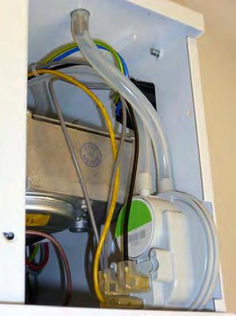
44 Slacken screw in burner lid and open the right hand burner access door. Connect extra sections of hose to each T piece. The two vacuum impulse hoses are in view. oth hoses are fitted with T pieces, one end of which has a blanking cap. Connect either a digital manometer or U tube gauge to the open ends of the hoses. Remove each blanking cap. Check reading against technical data. Doc No Page 44 of 60
 Replace burner on tube and secure. Reconnect gas hose. Open isolating valve.")

45 3.3 Commissioning chart Check installation has been carried out to these instructions. Ensure gas and electricity supplies are isolated. Disconnect gas hose from burner Remove burner from tube and inspect burner head. (See servicing instructions) Replace burner on tube and secure. Reconnect gas hose. Open isolating valve. Check soundness. Open control housing and check that all components are securely fastened. Check thermostat is set to maximum and is calling for heat. Switch on electrical supply. The red neon should now be illuminated. If restarting heater a delay of 15s should be allowed. The heater should now run through its start up sequence and ignite. Turn off power and check that all components are securely fastened. NO successful ignition is indicated by the amber light illuminating and remaining illuminated. Has the burner lit? YES Check gas pressure. Check operation on flame failure. Check gas pressure. Figure 19. Gas Valve adjustment Gas inlet test point (2.5mm llen key) Check operation of air pressure switch. djustment screw under cap to set injector pressure Injector pressure test point. (2.5mm llen key) Close control housing Leave the instructions with a responsible person. Doc No Page 45 of 60


 L M N K H C J C D Ducted ir Inlet Induced ir Inlet Gaskets Ignitor ssembly G F J E Neon s (Red/mber) D")
46 4. Servicing Instructions. These appliances should be serviced annually by a competent person to ensure safe and efficient operation. In exceptional dusty or polluted conditions more frequent servicing may be required. The manufacturer offers a maintenance service. Details available on request 4.1 Tools Required. The following tools and equipment are advisable to complete the tasks laid out in this manual. Suitable alternative tools may be used. Leather Faced Gloves Pozidrive Screwdriver Small Flat Head Screwdriver Large djustable Spanners or 22, 26 & 27mm Spanners for Fitting of Gas Flex. 12mm Spanner 4mm llen Key Manometer Wrench with 13mm Socket Soft rush 4.2 urner Description. Figure 20. Induced Herringbone urner: Model VSO UT/UH (refer to spares section 5) L M N K H C J C D Ducted ir Inlet Induced ir Inlet Gaskets Ignitor ssembly G F J E Neon s (Red/mber) D E Pepperpot Head K Gas Valve F Multi Hole Injector L Mains Input Socket G Ignition Controller M Fan Socket H Pressure Switch N Injector Carrier Doc No Page 46 of 60


47 Figure 21. Forced Gas urner: Model VSXO (refer to spares section 5) D E C G J I N M L F K E F G H H Ignition Probes Gas Valve Multi Hole Injector n.b. burner insulation omitted for clarity 2501/2507 or 2560 Fan I Neon's (Red/mber) Fan Inlet Spigot J Ignition Controller C Fan Orifice K Extrusion urner Head D Fan Mount Plate L Pepperpot Head E Fan Mount Plate Gasket M Pressure Switch Please refer to spares for burner components J Jet Carrier 4.3 urner Removal (ll Options) Step 1 Isolate mains electric and gas supplies. Step 2 Detach the gas supply as shown below, taking care to support the burner connection. Doc No Page 47 of 60


48 Step 3 On forced burners with ducted air attachment, slacken jubilee clip and remove flexible hose from the fan. disconnected by separating the connectors of the ignition lead assembly and removing the pressure switch silicon tube. Step 4 Slacken both grub screws on the burner support casting using a 4mm llen key to enable the burner to be removed from the radiant tube. Step 3 The gas injector can be inspected and replaced if contaminated or blocked. Step 5 Carefully remove the burner to prevent it or any components from falling to the ground and position the assembly in a safe area. When replacing the gas injector use a 12mm spanner and ensure approved thread sealant is used. Step 4 Refit the burner support casting and replace the gaskets to ensure effective sealing. 4.4 urner Gas Injector Servicing Step 1 Remove the burner support casting and gasket. 4.5 urner Head and Electrode Servicing Step 1 Check the pepper pot burner head for contamination. If necessary the head can be removed for cleaning of the inside of the burner head, see below. Step 2 The burner head assembly can be Doc No Page 48 of 60


49 Step 2 The pepper pot burner head can be replaced ensuring the 5 holes on the outer ring are aligned alongside the probes. Step 2 Loosen the 4mm grub screw and de-tatch the combustion fan. Step 3 The condition of the ignitor assembly can be checked for deterioration. However, we advise replacement at each service to ensure continued reliability. Step 4 Detach the electrode assembly from the burner head by removing the two screws and separating the ignitor lead connectors. Step 5 Check the positions and spark gap as shown below. Step 3 Remove the fan orifice plate spinning. Step 6 The burner assembly is ready to refit after servicing the combustion fan and the radiant tube assembly. 4.6 Combustion Fan ssembly Unitary heaters Step 1 Loosen the clamp fitting on the flue Figure 22. urner head detail Doc No Page 49 of 60


50 Step 4 Inspect the impeller and remove any dust with a soft brush. Step 5 Remove any dust from fan scroll and from around the motor. Step 6 Ensure the impeller rotates freely. Step 5 Inspect the impeller and remove any dust with a soft brush. Step 6 Remove any dust from fan scroll and from around the motor. Step 7 Refit components. 4.7 Combustion Fan ssembly Powered urner Step 1 Slacken jubilee clip and remove the flexible hose from the fan. Step 7 Ensure the impeller rotates freely. Step 8 Refit components. 4.8 Radiant Tube Servicing Step 1 rush any dust from the exterior of the tubes. Step 2 Remove fan fixings. Step 2 Inspect the fan and burner tubes visually. If the tubes appear clean, skip to servicing the reflector. Step 3 Remove the U bend (note: U end will be self colour not painted as photo below) Step 3 The combustion fan can now be detached. Step 4 Remove the fan orifice plate spinning. Doc No Page 50 of 60


51 Step 4 Withdraw the turbulators from the appliance. Carefully noting their condition and position. Replace turbulators if necessary. Step 2 Slacken casing support screws and remove heat exchanger from the radiant tube. Step 5 The turbulators should be cleaned with a soft brush. Step 3 Remove any dust and dirt from the heat exchanger & refit Reflector Servicing The condition of the reflectors should be noted. If necessary the reflectors can be cleaned with a mild detergent. This can significantly improve the efficiency of the appliance Inspection of Flue Step 6 If required the interior of the tubes can then be cleaned using an industrial vacuum cleaner or by using long poles and a scraper. Step 7 Refit components. 4.9 Heat Exchanger Servicing Step 1 Remove the flue connections. The flue needs to be inspected and cleaned if necessary or in accordance to the regulations of the country that the appliance is installed Re-commissioning fter Service fter servicing of the heater has been undertaken, it will be necessary to re-commission the heater as detailed in Section 3 of these instructions. Doc No Page 51 of 60


 VSO (Green)")
 2175")
 2180 Ignitor ssembly")

")

 (VSO15/20/25/30 Propane)")

 Rectification lead (purple)")
52 5. Spare Parts. Required Spares (refer to section 4.2) In order to aid troubleshooting and servicing we recommend that the components shown in this section should be stocked. Note ny spare part components that are not approved by mbirad could invalidate the approval of the appliance and validity of the warranty. Item Description Part No. Item Description Part No. Ignition Controller 2015S Pressure Switch: VSXO (Red) VSO (Green) Twin Gas Valve: See next page mber Neon (urner On) 2175 Pepperpot Head Red Neon (Mains On) 2180 Ignitor ssembly Combustion Fan See Section 1.11 Extruded urner Head Jet Carrier Injector See section 1.11 Jet Carrier (VSO / VSXO50 NG) Gasket (2off) Ducted ir Hose Flame Plates: (VSO20/25 NG & VSXO20/25 NG) (VSO15 NG) (VSO15/20/25/30 Propane) (VSO35/40/45/50 Propane) Hose Clamp 7541 Cables: Spark Electrode (black) Rectification lead (purple) Earth lead (green/yellow) GV Mini Harness Doc No Page 52 of 60


53 Gas Valves Note ny spare part components that are not approved by mbirad could invalidate the approval of the appliance and validity of the warranty. Original Description Replacement Part No. White Rodgers 36J42K-201 Nat Gas Valve Twin solenoid regulator 220/240V White Rodgers 36J41K-200 Propane Valve Twin solenoid regulator 220/240V Honeywell VK4105C Nat Gas Valve Twin solenoid regulator 220/240V Honeywell VK4105 Propane Valve Twin solenoid regulator 220/240V SIT Sigma Natural Gas Valve Twin solenoid regulator 220/240V SIT Sigma Propane Valve Twin solenoid regulator 220/240V Vision burners fitted with White Rogers gas valves part no s and can be replaced with the new Honeywell gas valve kit. This kit will take form of a valve, mini valve harness, rubber spacer and two off M4 x 10mm Screws. Part numbers shown above. Vision burners fitted with Honeywell valves part no s and can be replaced by the Honeywell gas valve kit. Vision burners currently fitted with SIT 840 Sigma Gas Valves part no s and can NOT be replaced with the Honeywell gas valve kit. SIT valves will be made available as spares. Doc No Page 53 of 60
54 6. Fault Finding Guide. Ensure gas & electricity supplies are enabled. YES YES Check: 1. urner controller 2. Red neon faulty Does the RED neon illuminate? NO Is there power on the burner? YES NO Check: 1. Operation of any thermostat 2. ny external fuses 3. Correct voltage is selected Does the combustion fan run? NO Check: 1. Wiring harness & plugs 2. Vacuum switch operation 3. Replace fan Check: 1. Vacuum switch tubes 2. Emitter tubes, air inlet & flue for obstructions 3. Operation of vacuum switch 4. Replace combustion fan YES NO Does the amber light illuminate after 10s purge? NO Does the vacuum switch `pull in`? Check: 1. urner controller 2. Wiring harness 3. mber neon faulty YES YES Does the amber light illuminate for 10s then go out? YES Is the burner sparking? NO Check: 1. Integrity of spark leads 2. Integrity of electrode assembly & spark gap 3. urner controller NO YES If the heater still fails to operate normally, please contact the mbirad service department. Does the gas valve open? YES NO Check: 1. urner controller 2. Replace gas valve Check: 1. urner inlet pressure 2. urner nozzle pressure 3. Check live & neutral polarity 4. Check presence of good earth Doc No Page 54 of 60
 Step 1 Slacken screw in burner lid")

 Step 1 Slacken screw in burner lid")


55 7. Replacing Parts urner Controller Replacement (VSXO) Step 1 Slacken screw in burner lid and open the right hand burner access door. Step 2 Undo 2 screws from controller bracket and remove. Disconnect burner controller from the wiring harness urner Controller Replacement (VSO) Step 1 Slacken screw in burner lid and open the right hand burner access door. Step 2 Disconnect burner controller from the wiring harness. Step 3 Disconnect the HT Lead from burner controller. Step 3 Disconnect the HT Lead from burner controller. Step 4 Remove the four screws attaching the controller to the bracket and remove. Step 4 Remove the two screws attaching the controller to the burner and remove. Step 5 Fit new burner controller Step 6 Refit HT leads and refit burner controller to wiring harness. Step 7 Test product and close access doors. Step 5 Fit new burner controller Step 6 Refit HT leads and refit burner controller to wiring harness. Step 7 Test product and close access door. Doc No Page 55 of 60

 Step 1 Disconnect")


56 7.2.1 Pressure Switch Replacement (VSXO) Step 1 Disconnect the two silicone impulse tubes and three wiring connections making note of replacement positions Pressure Switch Replacement (VSO) Step 1 Disconnect the two silicone impulse tubes and three wiring connections making note of replacement positions. Step 2 Remove the two screws as shown below. Step 2 Remove the two screws as shown below. Step 3 The air pressure switch can now be removed. Step 4 Fit the new air pressure switch ensuring the impulse tubes are connected as shown below. Step 3 The air pressure switch can now be removed. Step 4 Fit the new air pressure switch ensuring the impulse tubes are connected as shown below. Step 5 Test product and close access doors. Step 5 Test product and close access doors. Doc No Page 56 of 60


57 7.3 Gas Valve Replacement (VSXO shown) Step 1 Remove the burner assembly as described in the section 4.3 Servicing. Step 6 Detach the two screws holding the front of the gas valve. Step 3 Open the left hand access door and detach the impulse hoses from the air pressure switch. Step 7 Remove the four screws holding the rear burner plate in position plus the two screws from the gas valve flange. Step 4 Remove the 4 screws holding the burner head onto the burner assembly. Step 8 Remove the rear plate. Step 9 The jet carrier, gas inlet, and wiring harness can now be detached from the gas valve. Step 5 The burner head can now be detached by disconnecting the impulse tube and the burner head wiring. Step 10 The two screws retaining the gas valve can then be removed. Doc No Page 57 of 60
58 Step 11 The gas valve can now be replaced. Note: The White Rodgers gas valve will be replaced by a Honeywell VK valve kit part for Natural gas or for LPG Propane. Ensure correct valve is used for type of gas. Ensure the self adhesive rubber spacer is located between the valve input flange and the inside of the back plate prior to fixing. (Sticky side on valve flange). See opposite Step 12 Refit all components in reverse order. Step 13 SIT SIGM VLVES ONLY Ensure step screw is in the correct position as indicated in the diagram opposite. (For Natural Gas burners ONLY). Step Screw djustment Step 14 Set gas pressures to data badge or as per section 1.11 and ensure reliable burner performance. Step 15 HONEYWELL VK VLVES ONLY Check and reset Softlite setting to where necessary. See oposite. Step 16 Test product and close access doors. Doc No Page 58 of 60
59 Notes Doc No Page 59 of 60
. The red neon will then illuminate. 5.")
, or switch off electrical supply and restart after 15 seconds. 7.")
60 8. User & Operating Instructions. 8.1 To Start the Heater 1. Ensure gas supply is turned on. 2. Electrical supply to the controls is on. 3. Ensure that the controls are correctly set i.e.; Clock is correctly set. Heater program is correctly set. Required room temp is correctly set 4. Once the heating controller calls for heat power will be supplied to the heater(s). The red neon will then illuminate. 5. fter a pre-purge period of 10 seconds the burner will ignite and the amber neon will then illuminate. 6. If lockout occurs press the lockout reset button (if available), or switch off electrical supply and restart after 15 seconds. 7. If lockout occurs three times consecutively switch off and isolate the gas and electricity supplies. Contact the mbirad Service department To Switch Off Heater 1. Switch off electrical supply to the heater. The burner will stop and the fan will shut off. 2. If the heater is to be switched off for periods in excess of one week it is highly recommended that both the gas and the electrical supplies are turned off Routine Maintenance between Service Intervals fter ensuring that the heater is cold and mains electric isolated, cleaning of the reflectors with a soft cloth and a mild detergent (non solvent based cleaners only) in water can be undertaken. dditional removal of dust from the radiant tubes, burner and heat exchanger can be undertaken. 8.4 Frequency of Servicing The manufacturer recommends that to ensure continued efficient and safe operation of the appliance, the heater is serviced annually by a competent person e.g. every year in normal working conditions but in exceptional dusty or polluted conditions more frequent servicing may be required. The manufacturer offers a maintenance service. Details are available on request. For Service requirements, please contact mbirad. For further technical and service support visit our Support Information Database at NORTEK GLOL HVC (UK) LTD Fens Pool venue rierley Hill West Midlands DY5 1Q United Kingdom Tel: Fax: ambiradsales@nortek.com Document reference number G/VS/177/0813 Replaces G/VS/177/0212 Registered in England No Registered office: 10 Norwich Street, London, EC4 1D Doc No Page 60 of 60 Nortek Global HVC is a registered trademark of Nortek Global HVC Limited. ecause of continuous product innovation, Nortek Global HVC reserves the right to change product specification without due notice.
ASSEMBLY, INSTALLATION & SERVICING MANUAL FOR AMBIRAD VISION VS RANGE OF RADIANT TUBE HEATERS
 ASSEMBLY, INSTALLATION & SERVICING MANUAL FOR AMBIRAD VISION VS RANGE OF RADIANT TUBE HEATERS INDEX Section Introduction and Document Index Installation Requirements -------------------------------------------------1
ASSEMBLY, INSTALLATION & SERVICING MANUAL FOR REZNOR VISION VS RANGE OF RADIANT TUBE HEATERS
 ASSEMBLY, INSTALLATION & SERVICING MANUAL FOR REZNOR VISION VS RANGE OF RADIANT TUBE HEATERS INDEX WARNINGS Section Introduction and Document Index Installation Requirements -------------------------------------------------
AMBIRAD VISION VS RANGE RADIANT TUBE HEATERS INSTALLATION AND OPERATING MANUAL
 Instruction Manual. AMBIRAD VISION VS RANGE RADIANT TUBE HEATERS INSTALLATION AND OPERATING MANUAL INDEX Section Introduction and Document Index Installation Requirements -------------------------------------------------
AMBIRAD VISION VS RANGE RADIANT TUBE HEATERS INSTALLATION AND OPERATING MANUAL
 Instruction Manual. AMBIRAD VISION VS RANGE RADIANT TUBE HEATERS INSTALLATION AND OPERATING MANUAL Note: For use with all Vision VS models with Generation codes AA, AB & AC. (also for burners fitted with
ASSEMBLY, INSTALLATION & SERVICING MANUAL FOR AMBIRAD VISION VS RANGE OF RADIANT TUBE HEATERS
 ASSEMBLY, INSTALLATION & SERVICING MANUAL FOR AMBIRAD VISION VS RANGE OF RADIANT TUBE HEATERS INDEX Section Introduction and Document Index Installation Requirements -------------------------------------------------1
OPTIMA RADIANT TUBE HEATING SYSTEMS. Operation, maintenance and servicing manual
 OPTIM RDINT TUBE HETING SYSTEMS Operation, maintenance and servicing manual CONTENTS GENERL INSTRUCTIONS Section Title Page 1. Preparing the Installation 4 2. Checking the Installation rea 5 3. Flue Connection
ASSEMBLY, INSTALLATION & SERVICING MANUAL FOR AMBIRAD VISION VSX RANGE OF RADIANT TUBE HEATERS
 ASSEMBLY, INSTALLATION & SERVICING MANUAL FOR AMBIRAD VISION VSX RANGE OF RADIANT TUBE HEATERS INDEX Section Introduction and Document Index Installation Requirements -------------------------------------------------1
ASSEMBLY, INSTALLATION & SERVICING MANUAL FOR AMBIRAD VISION VSX RANGE OF RADIANT TUBE HEATERS
 ASSEMBLY, INSTALLATION & SERVICING MANUAL FOR AMBIRAD VISION VSX RANGE OF RADIANT TUBE HEATERS WR INDEX Section Introduction and Document Index Installation Requirements -------------------------------------------------1
INSTALLATION AND OPERATING MANUAL. Vision VS Radiant
 INSTALLATION AND OPERATING MANUAL Vision VS Radiant Radiant Tube Heater WARNINGS Nortek Global HVAC (UK) Limited equipment must be installed and maintained in accordance with the requirements of the Codes
AMBIRAD VISION SCHOOL HEATER KIT INSTALLATION MANUAL
 AMBIRAD VISION SCHOOL HEATER KIT INSTALLATION MANUAL REVISED 04/08/2011 AMBIRAD VISION SCHOOL HEATER KIT INSTALLATION MANUAL INDEX Section ASSEMBLY, INSTALLATION & SERVICING MANUAL FOR AMBIRAD VISION VS
U tube models PTU 09, 12, 15, 25, 30, 35, 40, 45. single linear tube models PTS 09, 12, 15, 25, 30, 35, 40, 45
 U tube models PTU 09, 2, 5, 25, 30, 35, 40, 45 & single linear tube models PTS 09, 2, 5, 25, 30, 35, 40, 45 installation, servicing & operating instructions INSTALLATION, SERVICING AND OPERATING INSTRUCTIONS
Model VSUS & VSLUS 120V 60Hz Gas-Fired, Tubular, Radiant, Low-Intensity Infrared Heater
 INSTALLATION / OPERATION / MAINTENANCE Applies to: Model VSUS & VSLUS 120V 60Hz Gas-Fired, Tubular, Radiant, Low-Intensity Infrared Heater OWNERS MANUAL WARNING: Improper installation, adjustment, alteration,
HERRINGBONE HB COMBINED FLUE SYSTEM
 HERRINGBONE HB COMBINED FLUE SYSTEM Index 1 2 3 4 5 6 7 General arrangement of Ambi-Rad Herringbone system Instructions and installation Manifold assembly Fan to flue arrangement Commissioning Control
AMBIRAD VISION VS RANGE RADIANT TUBE HEATERS SERVICING & COMMISSIONING MANUAL
 Instruction Manual. AMBIRAD VISION VS RANGE RADIANT TUBE HEATERS SERVICING & COMMISSIONING MANUAL Note: For use with all Vision VS models with Generation codes AA & AB. (also for burners fitted with SIT
AMBIRAD VISION VS RANGE RADIANT TUBE HEATERS SERVICING & COMMISSIONING MANUAL
 Instruction Manual. AMBIRAD VISION VS RANGE RADIANT TUBE HEATERS SERVICING & COMMISSIONING MANUAL Note: For use with all Vision VS models with Generation codes AA, AB & AC. (also for burners fitted with
ASSEMBLY, INSTALLATION & SERVICING MANUAL FOR AMBIRAD VSXUS INFRA-RED HEATERS
 ASSEMBLY, INSTALLATION & SERVICING MANUAL FOR AMBIRAD VSXUS INFRA-RED HEATERS INDEX Section Introduction and Document Index Installation Requirements ------------------------------------------------1 Assembly
INSTALLATION AND OPERATION INSTRUCTIONS OVERHEAD RADIANT TUBE HEATERS
 INSTALLATION AND OPERATION INSTRUCTIONS OVERHEAD RADIANT TUBE HEATERS Models: ADU5, ADU30, ADU35, ADU40, ADU45, ADL5, ADL30, ADL35, ADL40, ADL45 Single Stage Pull Through System (Negative Pressure) 0086
Herringbone Linked Flue System
 Herringbone Linked Flue ystem INTALLATION, ERVICING AND OPERATING INTRUCTION CBU09//5-HB, RU(ERU)5-HB, RU30/35/40/45-HB RL09//5-HB,RL5-HB, RL30/35/40/45-HB Gas Fired Products (UK) Ltd. Chapel Lane, Claydon,
AMBIRAD QUARTZ GLOW INSTANT INFRA-RED HEATERS INSTALLATION AND OPERATING MANUAL
 Instruction Manual AMBIRAD QUARTZ GLOW INSTANT INFRA-RED HEATERS INSTALLATION AND OPERATING MANUAL INDEX Section Introduction and Document Index Installation Requirements -------------------------------------------------
NOR-RAY-VAC CONTINUOUS RADIANT TUBE SYSTEM INSTALLATION AND OPERATING MANUAL
 Instruction Manual NOR-RAY-VAC CONTINUOUS RADIANT TUBE SYSTEM INSTALLATION AND OPERATING MANUAL INDEX Section Introduction and Document Index Installation Requirements ------------------------------------------------
ASSEMBLY INSTRUCTIONS - NXS SERIES. INFRARED RADIANT TUBE HEATER Single and Two Stage Pull Through System (Negative Pressure)
") ASSEMBLY INSTRUCTIONS - NXS SERIES OWNER / INSTALLER: For your safety this manual must be carefully and thoroughly read and understood before installing, operating or servicing this heater. INFRARED RADIANT
ASSEMBLY INSTRUCTIONS - NXS SERIES OWNER / INSTALLER: For your safety this manual must be carefully and thoroughly read and understood before installing, operating or servicing this heater. INFRARED RADIANT
BENSON LINEAR RADIANT TUBE
 BENSON LINEAR RADIANT TUBE Natural or Propane (Gas fired) I N S T A L L A T I O N C O M M I S S I O N I N G S E R V I C I N G U S E R I N S T R U C T I O N S September 2001 CONTENTS Page Compliance Notices
Model VPT 120V 60Hz Gas-Fired, Tubular, Radiant, Low-Intensity Infrared Heater
 INSTALLATION / OPERATION / MAINTENANCE Applies to: Model VPT 120V 60Hz Gas-Fired, Tubular, Radiant, Low-Intensity Infrared Heater Model VPT High/Low Burner/Control Box with 20-70 ft Tube/Reflector Length
OWNERS INSTRUCTION MANUAL
 OWNERS INSTRUCTION MANUAL 132CM/52 Classic INSTALLATION OPERATION MAINTENANCE CAUTION READ INSTRUCTIONS CAREFULLY FOR SAFE INSTALLATION AND FAN OPERATION. IF UNSURE CONSULT A QUALIFIED ELECTRICIAN SUITABLE
INSTALLATION AND OPERATION INSTRUCTIONS Double Linear OVERHEAD RADIANT TUBE HEATERS Models: PTDSL 15, PTDSL 25, PTDSL 30, PTDSL 35, PTDSL 40, PTDSL 45
 INSTALLATION AND OPERATION INSTRUCTIONS Double Linear OVERHEAD RADIANT TUBE HEATERS Models: PTDSL 15, PTDSL 25, PTDSL 30, PTDSL 35, PTDSL 40, PTDSL 45 Single Stage Pull Through System (Negative Pressure)
INSTALLATION AND OPERATION INSTRUCTIONS OVERHEAD RADIANT TUBE HEATERS
 INSTALLATION AND OPERATION INSTRUCTIONS OVERHEAD RADIANT TUBE HEATERS Models: PTUL 5, PTUL 0, PTUL 5, PTUL 0, PTUL 5, PTSL 5, PTSL 0, PTSL 5, PTSL 0, PTS L5 Single Stage Pull Through System (Negative Pressure)
INSTALLATION AND OPERATION INSTRUCTIONS OVERHEAD RADIANT TUBE HEATERS
 INSTALLATION AND OPERATION INSTRUCTIONS OVERHEAD RADIANT TUBE HEATERS Models: LRU5, LRU5, LRU0, LRU5, LRU0, LRU5, LRL5, LRL5, LRL0, LRL5, LRL0, LRL5 Single Stage Pull Through System (Negative Pressure)
Installation and Maintenance
 1.0 INTRODUCTION MRXBOXAB-ECO-LP1SW (Standard Unit) MRXBOXAB-ECO-LP1-OHSW (Opposite Hand Unit) Mechanical Ventilation Unit with Heat Recovery for Ceiling Void Mounting Installation and Maintenance The
OPTIONAL SPRING MTG HANGING CENTRES WATER CONN'S: TWO BSP MALE. 19 mm (3/4") ELECTRICAL CONDUIT HOLES ACCESS PANEL OUT (WATER) IN 485 MOUNTING
 ELECTRICAL CONDUIT HOLES ACCESS PANEL OUT (WATER) IN 485 MOUNTING") HWP 117 225 Ducted Water Cooled R410A Packaged Air Conditioner Dimensions (mm) Fig. 1 HWP 117 60 1210 SPRING MOUNTING CENTRES 690 (HEIGHT = 370) FILTER BOX PROJECTION Net Weight 105 kg Installation & Maintenance
HWP 117 225 Ducted Water Cooled R410A Packaged Air Conditioner Dimensions (mm) Fig. 1 HWP 117 60 1210 SPRING MOUNTING CENTRES 690 (HEIGHT = 370) FILTER BOX PROJECTION Net Weight 105 kg Installation & Maintenance
S D HWP 77, 96. Ducted Water Cooled R410A Packaged Air Conditioner. Installation & Maintenance. Fig. 1 Nomenclature. Fig.
 HWP 77, 96 Ducted Water Cooled R410A Packaged Air Conditioner Installation & Maintenance Fig. 1 Nomenclature Nomenclature e.g. H W P 7 7 C K Series Size Type S D GENERAL HWP - A general designation which
S Y D. HWP 35, 47, 58 (c/w EC Motor & UC7 Controller) Ducted Water Cooled R410A Packaged Air Conditioner. Installation & Maintenance
 Ducted Water Cooled R410A Packaged Air Conditioner. Installation & Maintenance") HWP 35, 47, 58 (c/w EC Motor & UC7 Controller) Ducted Water Cooled R410A Packaged Air Conditioner Installation & Maintenance Fig. 1 Nomenclature Nomenclature e.g. H W P 3 5 C K Series Size Type S Y D GENERAL
HWP 35, 47, 58 (c/w EC Motor & UC7 Controller) Ducted Water Cooled R410A Packaged Air Conditioner Installation & Maintenance Fig. 1 Nomenclature Nomenclature e.g. H W P 3 5 C K Series Size Type S Y D GENERAL
Installation Instructions
 Issue 1.2 August 2015 Balanced Flue Kit for NVx and VPC Industrial & Commercial Heating Systems. Installation Instructions H E A T I N G / / V E N T I L A T I O N / / A I R C O N D I T I O N I N G Page
EUTECTIC EC-10DV Series
 EUTECTIC EC-10DV Series DIRECT VENT OIL-FIRED WATER BOILER/NO. 2 OIL VENTING INSTALLATION INSTRUCTIONS CONTENTS..........................................PAGE Basic Guidelines..........................................1
Installation and Maintenance
 1.0 INTRODUCTION MRXBOXAB-ECO-LP1 (Standard Unit) MRXBOXAB-ECO-LP1-OH (Opposite Hand Unit) Mechanical Ventilation Unit with Heat Recovery for Ceiling Void Mounting Installation and Maintenance The LP1
AB RANGE GAS FIRED ROOM SEALED AIR CURTAIN INSTALLATION AND OPERATING MANUAL
 AB RANGE GAS FIRED ROOM SEALED AIR CURTAIN INSTALLATION AND OPERATING MANUAL INDEX Section General Information ------------------------------------------------------------ 1 Dimensions ------------------------------------------------------------------------
Line Pressure ( w.c.) Gas Supply Min. Max. Pressure ( w.c.) Natural Gas Propane Gas
 Gas Supply Min. Max. Pressure ( w.c.) Natural Gas Propane Gas") HVAC Guideline Specifications WHISPER-JET: SET SERIES Two Stage Positive Pressure Gas-Fired Infrared Radiant Tube Type Heater Commercial/Industrial Applications Technical Summary Input Range: 80,000/60,000
HVAC Guideline Specifications WHISPER-JET: SET SERIES Two Stage Positive Pressure Gas-Fired Infrared Radiant Tube Type Heater Commercial/Industrial Applications Technical Summary Input Range: 80,000/60,000
Installation and Operating Manual Drying Cabinet
 Drying Cabinet TS-4175 WW CONTENTS THIS USER MANUAL & DATA PLATE DETAILS Page 2 IMPORTANT SAFETY INSTRUCTIONS Page 3 INSTALLATION INSTRUCTIONS Page 4 OPERATING INSTRUCTIONS Page 8 MAINTENANCE INSTRUCTIONS
INSPECT all combustion air openings into the building and, if necessary, clear as they become blocked by litter, dust, feathers or other matter.
 INSTALLATION AND OPERATION INSTRUCTIONS INFRARED RADIANT IP55 POULTRY TUBE HEATER Single Stage Pull Through System (Negative Pressure) Models: SRLP (30, 35, 40, 45) IP55 0086 OWNER / INSTALLER: For your
Ca 6s and BCa 6s kw INSTALLATION AND OPERATING INSTRUCTIONS. Page 1 31/07/00
 Ca 6s and BCa 6s 33-64 kw INSTALLATION AND OPERATING INSTRUCTIONS Page 1 CONTENTS: General specification Dimensions for Ca6s and BCa6s boilers. Boiler room clearance requirements Boiler block assembly
OCH-SS series Direct Wired Units Indoor * and Outdoor Comfort Heaters
 1200 North Main Street Fostoria, OH 44830 Phone: 800-495-4525 Fax: 419-435-0842 A DIVISION OF www.fostoriaindustries.com OCH-SS series Direct Wired Units Indoor * and Outdoor Comfort Heaters *EXCLUDING
... Vision Radiant Tube Heating Systems ... ErP. ErP Lot 20 Seasonal Efficiency and NOx compliant
 Vision Radiant Tube Heating Systems ErP 2018 ErP Lot 20 Seasonal Efficiency and NOx compliant * Vision... Radiant Tube Heating Systems... The range of high efficiency Vision radiant tube heaters delivers
AMBIRAD.... Vision Radiant Tube Heating Systems...
 AMBIRAD Vision Radiant Tube Heating Systems * Vision... Radiant Tube Heating Systems... Renowned for its pioneering track record, AmbiRad, Europes leading supplier of radiant tube heating systems, has
GAS FIRED AIR CURTAIN AB 175, AB 225
 Instruction Manual. GAS FIRED AIR CURTAIN AB 175, AB 225 INDEX Section General Information ----------------------------------------------------------- 1 Dimensions -----------------------------------------------------------------------
Blackheat. Vacuum Assisted Linear, Double Linear, U-Tube, and Multi-Burner Gas Fired Heating Systems. Installation, Operation & Service Manual WARNING
 FOR YOUR SAFETY If you smell gas: 1. Open windows. 2. DO NOT try to light any appliance. 3. DO NOT use electrical switches. 4. DO NOT use any telephone in your building. 5. Extinguish any open flame. 6.
Corr/Guard PRESSURE RATED VENTING SYSTEM IMPORTANT: DO NOT INSTALL WITHOUT FIRST READING THESE INSTRUCTIONS VERY CAREFULLY.
 CORR/GUARD INSTALLATION INSTRUCTIONS This symbol on the nameplate means this product is listed by Underwriters Laboratories Inc. Tested to UL1738 / CAN / ULCS636-1995 Listing No. MH26687 Testing No. 11EN
INFRARED IP55 HEATER INSTRUCTIONS FOR: MODEL:- QZWP45N 1. SAFETY INSTRUCTIONS
 INSTRUCTIONS FOR: INFRARED IP55 HEATER MODEL:- QZWP45N Thank you for purchasing a Consort Claudgen product. Manufactured to a high standard this product will, if used according to these instructions and
TC MODULE (FFD) (with Gas Hob)
 (with Gas Hob)") TC MODULE (FFD) (with Gas Hob) Installation Instructions REMEMBER: when replacing a part on this appliance, use only spare parts that you can be assured conform to the safety and performance specification
TC MODULE (FFD) (with Gas Hob) Installation Instructions REMEMBER: when replacing a part on this appliance, use only spare parts that you can be assured conform to the safety and performance specification
DC Heat Recovery Unit MVHR Wholehouse heat recovery unit
 DC Heat Recovery Unit MVHR Wholehouse heat recovery unit Stock Ref. N DC Heat Recovery Unit MVHR 443423 Installation, Maintenance & Users Instructions PLEASE READ INSTRUCTIONS IN CONJUNCTION WITH ILLUSTRATIONS.
Nor-Ray-Vac Modulating
 ASSEMBLY MANUAL Nor-Ray-Vac Modulating Continuous Radiant Tube System WARNINGS Nortek Global HVAC (UK) Limited equipment must be installed and maintained in accordance with the requirements of the Codes
Compact. Installation & Servicing Instructions THESE INSTRUCTIONS TO BE RETAINED BY USER
 Compact Installation & Servicing Instructions THESE INSTRUCTIONS TO BE RETAINED BY USER Contents Design principles and operating sequence Page 1.1 Principle components 2 1.2 Central heating mode 2 1.3
Blackheat HE. Vacuum Assisted Linear, Double Linear, U-Tube, and Multi-Burner Gas Fired Heating Systems. IP55 Protected Burner Box
 FOR YOUR SAFETY If you smell gas: 1. Open windows. 2. DO NOT try to light any appliance. 3. DO NOT use electrical switches. 4. DO NOT use any telephone in your building. 5. Extinguish any open flame. 6.
Installation and Maintenance
 MRXBOX95B-LP1 (Standard Unit) MRXBOX95B-LP1-OH (Opposite Hand Unit) Mechanical Ventilation Unit with Heat Recovery & Summer Bypass for Ceiling Void Mounting Installation and Maintenance The EMC Directive
Heat Exchanger Block Replacement Instructions
 Series 1-4 Gas-fired water boiler Heat Exchanger Block Replacement Instructions Ultra-80 S1-4 Heat Exchanger Block Replacement Kit, Part No. 383-500-773 Ultra-105 S1-4 Heat Exchanger Block Replacement
Installation Instructions. For the 18 Built-In Dishwasher and Front Color Panels
 Installation Instructions For the 18 Built-In Dishwasher and Front Color Panels Printed in USA 154232102 Before You Begin DO NOT INSTALL DISHWASHER UNTIL YOU HAVE READ ALL INSTRUCTIONS. FOR YOUR SAFETY,
Lo-Carbon T-series Window & Roof Models
 Lo-Carbon T-series Window & Roof Models Installation & User Instructions WIRED 456165A (9 WW) 456168A (9 RF) 456173A (12 WW) 456176A (12 RF) WIRELESS 456169A (9 WW) 456172A (9 RF) 456177A (12 WW) 456180A
PLEASE READ INSTRUCTIONS IN CONJUNCTION WITH ILLUSTRATIONS.
 Silhouette Lo-Carbon RANGE 100/150mm AXIAL EXTRACT FAN Installation and Wiring Instructions Stock Ref. N 44 16 24-100B 44 16 25-100T 44 16 26-100HT 44 16 28-150B 44 16 29-150T 44 16 30-150HT 220-240V~50Hz
COMMERCIAL GAS AND ELECTRIC STACKED WASHER/ DRYER INSTALLATION INSTRUCTIONS
 COMMERCIAL GAS AND ELECTRIC STACKED WASHER/ DRYER INSTALLATION INSTRUCTIONS MODELS MLG19PD, MLE19PD The installation, including a proper exhaust system, is the responsibility of the owner. LEAVE THESE
Twin Wall Installation Instructions And Maintenance Guide
 Twin Wall Installation Instructions And Maintenance Guide Please read all instructions before beginning your installation. Failure to install this system in accordance with these instructions will invalidate
CARVER CASCADE 2 & CASCADE 2 GE CARAVAN WATER HEATER INSTALLATION INSTRUCTIONS LEAVE THESE INSTRUCTIONS WITH THE USER
 CARVER - CASCADE 2 & CASCADE 2 GE CARAVAN WATER HEATER INSTALLATION INSTRUCTIONS LEAVE THESE INSTRUCTIONS WITH THE USER 1:0 SPECIFICATIONS Water capacity Water connections Water supply 9 litres (2 gallons)
Cooker Hood BAH61&BAH91 BAH60&BAH90 BAH93CG&BAH93CGIS BAH94FG&BAH94FGIS. User Manual for your
 User Manual for your BAH61&BAH91 BAH60&BAH90 BAH93CG&BAH93CGIS BAH94FG&BAH94FGIS Cooker Hood NOTE: This User Instruction Manual contains important information, including safety & installation points, which
breeze easytm model # F100-1W
 DewStop breeze easytm model # F100-1W Installation Guide Read and Save These Instructions LISTED Questions, Problems, Missing Parts? Please Call 1-360-876-2974 or E-Mail info@dewstop.com please retain
Heater Install Manual
 Heater Install Manual INSTALLATION / OPERATION / MAINTENANCE Applies to: ULT Series 120V 60Hz Gas- Fired, Tubular, Radiant, Low- Intensity Infrared Heater Model PT (Harsh Environment) On/Off & High/Low
SHORT WAVE INFRARED PANEL DRYER
 INSTRUCTIONS FOR: SHORT WAVE INFRARED PANEL DRYER MODEL: IR3000 Thank you for purchasing a Sealey product. Manufactured to a high standard this product will, if used according to these instructions and
Flue & Flue Kits for NVx, VPC & NVS
 Doc Ref: M505 Issue 2.1 Mar 2018 Flue & Flue Kits for NVx, VPC & NVS Industrial & Commercial Heating Systems Installation Manual www.powmatic.co.uk +44 (0) 1460 53535 info@powrmatic.co.uk powrmatic Certificate
Bosch Group. 15SBi / 24SBi. WALL MOUNTED BOILERS FOR CENTRAL HEATING and Indirect supply of domestic hot water
 Bosch Group 15SBi / 24SBi WALL MOUNTED BOILERS FOR CENTRAL HEATING and Indirect supply of domestic hot water INSTALLATION AND SERVICING INSTRUCTIONS 24SBi This appliance is for use with Natural Gas or
FLANGED CORR/GUARD CORR/GUARD INSTALLATION INSTRUCTIONS
 CORR/GUARD INSTALLATION INSTRUCTIONS This symbol on the nameplate means this product is listed by Underwriters Laboratories Inc. Tested to UL1738 / CAN / ULCS636-08 Listing No. MH26687 Testing No. 11EN
Installation Instructions
 Installation Instructions KFN 9855 ide en - CA Installation, repair and maintenance work should be performed by a Miele authorized service technician in accordance with national and local safety regulations
BENSON.... Variante3 Fired Unit Heaters...
 NSON Variante3 as ired Unit Heaters 3 Variante... as ired Unit Heaters... The new Variante3 builds on the technical excellence of the previous range to provide cost effective and robust heating for industrial
SMALL DIAMETER CORR/GUARD & SLEEVED CORR/GUARD
 CORR/GUARD INSTALLATION INSTRUCTIONS This symbol on the nameplate means this product is listed by Underwriters Laboratories Inc. Tested to UL1738 / CAN / ULCS636-08 Listing No. MH26687 Testing No. 11EN
ferroli Boiler Replacement Maxima 35C- Modena HE
 ferroli Boiler Replacement Maxima 35C- Modena HE Introduction Although the new Ferroli Modena 32C HE high efficiency condensing combination boiler has an output slightly less than that of the Ferroli Maxima
Pellet Stove. Flex Pipe. Appliance Connector
 Installation Instructions & Owners Maintenance Guide DT-M Direct-Temp for Multi Fuel L-Vent / Vent System for Pellet, Corn and other Bio-Fuel Burning Appliances Introduction Direct-Temp for Multi-Fuel
WARNING: Improper installation, adjustment, alteration, service or maintenance can cause property damage, injury or death. Read the installation,
 WARNIN: Improper installation, adjustment, alteration, service or maintenance can cause property damage, injury or death. Read the installation, operating and maintenance instructions thoroughly before
Assessment Schedule - TS.6
 The Assessor shall determine the business s commitment and support to good and safe working practices; also that it has a positive culture in all aspects of its work. In particular, the assessor shall
Low-Intensity, Infrared Heating Systems Submittal: HE Series
 Low-Intensity, Infrared Heating Systems Submittal: HE Series Job: Location: Engineer: Gas Specs: Date: QTY. MODEL NO. HE UNIT INPUT BTU/HR QTY. MODEL NO. HE UNIT INPUT BTU/HR QTY. MODEL NO. HE UNIT INPUT
Direct Vent Training & Installation Instructions for Venting 40/50 gallon models Telescoping Vent Kit (standard)
") Choosing Location of the water heater This water heater is of the direct vent design. It takes all of its fresh air for combustion from outside the building which it is installed. It also vents the combustion
Choosing Location of the water heater This water heater is of the direct vent design. It takes all of its fresh air for combustion from outside the building which it is installed. It also vents the combustion
SIME FORMAT WALL HUNG BOILERS MODEL 34i AND MODEL 34e. cod A
 cod. 6272262A GENERAL DATA Heating Data Heat Output Input (Adjustable) (Adjustable) Format 34i 11.2 34KW 45 145MJ/hr Format 34e 11.2 34KW 45 145MJ/hr General Specifications FORMAT 34i 34e Main burner injectors
Compact HE. High efficiency combi boiler. Installation & Servicing Instructions THESE INSTRUCTIONS TO BE RETAINED BY USER
 Compact HE High efficiency combi boiler Installation & Servicing Instructions THESE INSTRUCTIONS TO BE RETAINED BY USER Vokèra is a licensed member of the Benchmark scheme which aims to improve the standards
PLEASE READ ALL SECTIONS OF THIS GUIDE BEFORE COMMENCING YOUR INSTALLATION AND IN CONJUNCTION WITH YOUR DRAWINGS.
 Installation Guide This information is provided as a guide and may differ from project to project. It is assumed that the property is a two storey dwelling. Obviously a bungalow represents a simpler task,
Installation and Maintenance
 MRXBOXAB-ECO4 (Standard Unit) MRXBOXAB-ECO4-OH (Opposite hand Unit) Mechanical Ventilation Units with Heat Recovery and Heat Exchanger Bypass for Wall Mounting Installation and Maintenance The EMC Directive
INSTALLATION AND OPERATION INSTRUCTIONS. INFRARED RADIANT TUBE HEATER Two Stage Pull Through System (Negative Pressure)
") INSTALLATION AND OPERATION INSTRUCTIONS OWNER / INSTALLER: For your safety this manual must be carefully and thoroughly read and understood before installing, operating or servicing this heater. INFRARED
INSTALLATION AND OPERATION INSTRUCTIONS OWNER / INSTALLER: For your safety this manual must be carefully and thoroughly read and understood before installing, operating or servicing this heater. INFRARED
T-SERIES. Window & Roof Models. Installation, Set-up and Operating Instructions. 230V/1/50Hz
 T-SERIES Window & Roof Models Installation, Set-up and Operating Instructions Stock Ref. Nos. WIRED 456165A (9" WW) 456168A (9" RF) 456173A (12" WW) 456176A (12" RF) WIRELESS 456169A (9" WW) 456172A (9"
ATMOSPHERIC GAS BOILER INSTALLATION, OPERATING AND MAINTENANCE MANUAL
 STREBEL GENEVA CE ATMOSPHERIC GAS BOILER INSTALLATION, OPERATING AND MAINTENANCE MANUAL INDEX TABLE 1 TECHNICAL DATA SECTION 1 SECTION 2 SECTION 3 SECTION 4 SECTION 5 SECTION 6 SECTION 7 SECTION 8 SECTION
JOHN DEERE GATOR HPX/XUV 2 PASSENGER HEATER INSTALLATION INSTRUCTIONS (p/n: 9PH20S30)
") P. 1 of 12 JOHN DEERE GATOR HPX/XUV 2 PASSENGER HEATER INSTALLATION INSTRUCTIONS (p/n: 9PH20S30) Item: Qty: Description: 1 2 1 x 1 x 5/8 Tee Fitting 2 2 Plastic Snap-in Hose Grommet 3 4 1-1/2" Hose Clamps
P. 1 of 12 JOHN DEERE GATOR HPX/XUV 2 PASSENGER HEATER INSTALLATION INSTRUCTIONS (p/n: 9PH20S30) Item: Qty: Description: 1 2 1 x 1 x 5/8 Tee Fitting 2 2 Plastic Snap-in Hose Grommet 3 4 1-1/2" Hose Clamps
Wall hung combination boiler PROTHERM 23 BTVE
 Wall hung combination boiler PROTHERM 23 BTVE User, Installation and Servicing Instructions 6187 The boiler serial number is marked on the label attached to the inside of the drop down door. Refer to the
Installation and Maintenance
 38 70 = 100 410 = 60 1.0 INTRODUCTION MRXBOXAB-ECO4-AESW (Standard Unit) MRXBOXAB-ECO4-AEOHSW (Opposite hand Unit) Mechanical Ventilation Units with Heat Recovery for Wall Mounting Installation and Maintenance
... RHeco. High Efficiency Condensing Unit Heaters... Low NO x. ErP. ErP Lot 21 Seasonal Efficiency and NOx compliant
 ... RHeco... ErP 2021 ErP Lot 21 Seasonal Efficiency and NOx compliant RHeco...... Reznor continue their tradition of manufacturing high efficiency warm air heating equipment with the introduction of the
Installation and Servicing Instructions
 Installation and Servicing Instructions Alpha HE CB25/33 and HE SY25 Wall Mounted, Fan Assisted, Room Sealed, Gas Fired, High Efficiency Condensing Boiler Range For Technical help or for Service call...
INSTALLATION AND OPERATION INSTRUCTIONS. INFRARED RADIANT TUBE HEATER Single Stage Pull Through System (Negative Pressure)
") INSTALLATION AND OPERATION INSTRUCTIONS OWNER / INSTALLER: For your safety this manual must be carefully and thoroughly read and understood before installing, operating or servicing this heater. INFRARED
INSTALLATION AND OPERATION INSTRUCTIONS OWNER / INSTALLER: For your safety this manual must be carefully and thoroughly read and understood before installing, operating or servicing this heater. INFRARED
Vertical Termination Part No: 3CGRVT 16 7/8" 18 Vent Pipe Extension Part No: 3CG18 9 7/8" Wall Hanger Part No: 3CGWH 7 7/8" 7 3/8"
 Corr/Guard Direct Vent Water Heater Vent/Air Intake System Installation and service must be performed by a qualified installer, service agency or the gas supplier. Installation must meet all state and
Alpha CD13R,18R and 24R
 Installation and Servicing Instructions Alpha CD3R,8R and 24R Wall Mounted, Fan Assisted, Room Sealed, Gas Fired, High Efficiency Condensing Regular Boiler Range For Technical help or for Service call...
Model No: Little Devil II (inc ss)
") GAS HEATER Model No: Little Devil II (inc ss) PART NO: 6926020, 6926025 (SS) OPERATION & MAINTENANCE INSTRUCTIONS LS1213 INTRODUCTION Thank you for purchasing this CLARKE Gas Heater. Before attempting
GAS HEATER Model No: Little Devil II (inc ss) PART NO: 6926020, 6926025 (SS) OPERATION & MAINTENANCE INSTRUCTIONS LS1213 INTRODUCTION Thank you for purchasing this CLARKE Gas Heater. Before attempting
TECHNICAL MANUAL CX(E) SPLIT SYSTEMS. Tel: Fax:
 SPLIT SYSTEMS. Tel: Fax:") TECHNICAL MANUAL CX(E) SPLIT SYSTEMS CONTENTS INDEX PART NUMBERS, OPTIONS, UNIT COMBINATIONS, DIMENSIONS & WEIGHTS 3 PERFORMANCE DATA & AIR FLOW 4 SOUND POWER AND SOUND PRESSURE LEVELS 5 ELECTRICAL DATA
TECHNICAL MANUAL CX(E) SPLIT SYSTEMS CONTENTS INDEX PART NUMBERS, OPTIONS, UNIT COMBINATIONS, DIMENSIONS & WEIGHTS 3 PERFORMANCE DATA & AIR FLOW 4 SOUND POWER AND SOUND PRESSURE LEVELS 5 ELECTRICAL DATA
POWERFLOW Series. Unvented Electric Storage Water Heaters. Installation & Operating Instructions Manual
 POWERFLOW Series Unvented Electric Storage Water Heaters Installation & Operating Instructions Manual These Instructions must be left with the user after installation. Version 3.0 June 2009 Hyco POWERFLOW
Lo-Carbon Quadra Centrifugal Fan
 Lo-Carbon Quadra Centrifugal Fan Installation and Wiring Instructions Stock Ref. N Quadra TP Quadra TM Quadra HTP 439251A 439253A 439181A 220-240V~50Hz IPX4 PLEASE READ INSTRUCTIONS IN CONJUNCTION WITH
Servicing manual. Wall-mounted condensing gas boiler 600 Series - 11S / 19S / 24S / 24C /2002 GB(EN) For trade use
 For trade use") GB122 7210 1300-12/2002 GB(EN) For trade use Servicing manual Wall-mounted condensing gas boiler 600 Series - 11S / 19S / 24S / 24C Please read thoroughly before attempting to diagnose fault List of contents
GB122 7210 1300-12/2002 GB(EN) For trade use Servicing manual Wall-mounted condensing gas boiler 600 Series - 11S / 19S / 24S / 24C Please read thoroughly before attempting to diagnose fault List of contents
1. SAFETY RULES. 8. Avoid placing objects in the path of the blades.
 1 1. SAFETY RULES 1. To reduce the risk of electric shock, insure electricity has been turned off at the circuit breaker or fuse box before beginning. 2. All wiring must be in accordance with the National
VPC Gas Cabinet Heater Range
 VPC Gas Cabinet Heater Range Industrial & Commercial Heating Systems. www.powrmatic.co.uk HEATING // VENTIATION // AIR CONDITIONING // OEM PRODUCTS VPC Overview Models Available VPC UF - Upright Freeblowing
Installation and maintenance instructions
 6304 4995 0/004 GB For installer Installation and maintenance instructions Flue gas heat exchanger WT50/60 Please read thoroughly prior to installation and maintenance. Summary About this manual This equipment
BWT6.3GL Cooker Hood 60 cm Glass chimney hood
 User Manual for your BWT6.3GL Cooker Hood 60 cm Glass chimney hood NOTE: This User Instruction Manual contains important information, including safety & installation points, which will enable you to get