120+ Get your job done swiftly Easy selection of your application is the key. applications.
|
|
|
- Kevin Hoover
- 5 years ago
- Views:
Transcription


1 Application guide for ECL Comfort controllers Get your job done swiftly Easy selection of your application is the key The ECL Comfort series offers an optimum range of electronic controllers for temperature control in heating and domestic hot water systems. In this guide, you will find the full range of applications, intuitively described and illustrated for you to plan and design systems with confidence applications covered by ECL application keys.
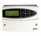
2 Electronic controllers from : Only a few products for an endless number of applications Based on the success and benefits of previous generations, the ECL Comfort 210 and 310 controllers ensure comfort and convenience for heating, cooling and domestic hot water systems. The components of ECL Comfort The ECL Comfort range consists of ECL Comfort 110, 210 and 310 each in an elegant and timeless Scandinavian design. ECL Comfort 110 is the choice for basic heating systems, for which the installer or user prefer a traditional operation. ECL Comfort 210 appeals to users who prefer an increased number of options. The series offers many functional options and can be used for commercial installations. Two control circuits + thermostatic function, optimizer function, 3-point control of actuators, Modbus communication for smaller SCADA systems etc. ECL Comfort 310 is the advanced controller with a large number of functions, such as: Three control circuits + thermostatic function, optimizer function, 3-point control of actuators, Modbus/M-bus/Ethernet communication etc. The intelligent key concept for ECL Comfort 210/310 ensures optimum user-friendliness of these advanced controllers. The ECL Comfort range also comprises an elegantly designed remote control in two versions, which can access all parameters in the controller. The future is in the keys The ECL Comfort range and its advanced software key not only meet your present demands but also the future requirements you might have for heating control. With ECL Comfort 210/310 new demands are covered by new keys with new settings. The few basic models and the large variety of ECL keys give you a considerably better and quicker overview of the unique application opportunities offered by the ECL Comfort range. Menus are available in multiple languages. By means of the chosen key, it is easy to set the controller and change the factory settings precisely to the relevant type of system and required settings. The schedule in the ECL Comfort can be programmed for each day in the week. The building will be heated in the comfort periods you request; also holidays can be scheduled on beforehand. This is environmentally sound and saves money. Some features of ECL Comfort: Optimizer and boost function Anti-bacteria function (DHW circuit) Holiday program 2 Return temperature limitation based on outdoor temperature Frost protection Heating cut out function Year clock and automatic changeover between summer and winter time Copy function to/from the intelligent ECL key Communication via the standardized R85/TCP/IP, M-bus and Modbus options Motor protection Automatic saving Menus in multiple languages Master/slave functions Log and alarm Analog input/output Refill water function Two pump control
3 33
4 Automatic setup of DHW parameters A precondition for a well functioning heating system is that the correct settings are made before it is put to use. Adjustments are necessary to preset the control parameters. Presetting gives the following benefits: A high degree of comfort Improved protection against lime deposits in DHW heat exchangers Energy saving Long operating life Minimum service The introduction of automatic setting of control parameters on the controller itself, i.e. auto tuning and motor protection, gives optimum control of the DHW system. This ensures a high degree of comfort, stable control during idle operation and, subsequently, longer motor life. The setting of control parameters can thus be reduced to one easy and reliable procedure. Auto tuning is especially necessary in DHW systems. How to do auto tuning with ECL Comfort? Open for the tap water to get a constant tapping load Activate auto tuning by pushing a button Wait 7-25 minutes to complete the tuning 90 The result of Auto Tuning 4 Tap water temperature ( C) Time (min.) Tap water ( C) Sec. flow (m 3 /h) Flow rate (m 3 /h)


5 Intelligent communication solutions Our solutions are wide-ranging in every respect. We cover almost every area of application. From busy cities and suburbs to idyllic villages as well as from public or commercial buildings to residential homes. Intelligent solutions intelligent communication communication solutions provide the ultimate in control. We don t just supply controllers, but unique software which facilitates remote monitoring and control of district heating systems. Our offering ranges from standard software fully integratable with the existing plant and buildings, to complete systems with full support. Your future communication platform Remote monitoring and communication is the future as of today. Our solutions cover traditional forms of district heating and alternatives, such as biomass plants. A platform will provide better, and simplified control over a system, which not only optimizes the control processes, but also yields savings and protects the environment. In some networks you have large pumps and large controllers leading to substantial energy usage. Here it is important with an optimized district heating network. An electronic controller will not only simplify plant management, it will also save energy. Act proactive to service communication solutions enable you to act pro-actively to provide better service. Thanks to efficient monitoring and alarm systems, they can isolate and remedy problems even before the customer knows they exist. For example; if the flow temperature is incorrect, the system will automatically activate an alarm, to warn about excessive energy consumption. There are many good reasons to choose a solution which allows you to monitor, control and therefore service your system remotely, regardless of whether the system services buildings in urban areas or rural communities. has and will supply an advantageous solution for you. For optimum control in any system Your requirements have been combined with our know-how to extend and innovate our product range. markets a comprehensive range of motorized control valves with features that give an optimum fit with the ECL Comfort controller. Our control valves are available in multiple sizes, different materials and with a variety of connections. The range of motorized control valves meet the requirements in any of these applications: Terminal and zone Heating and cooling District heating Steam 55

6 ENERGY SAVING AND COMFORT IS A MATTER OF OPTIMUM ENERGY CONTROL When you look at urban and rural areas with varying housing densities, the selection of heat sources for each individual building will differ. Where available, district heating will most often be a part of the solution. District heating benefits the individual homeowner or tenant as well as the society at large. Where district heating is not available, individual solutions will be used preferably in combination with renewable energy sources. One of the solutions for achieving energy savings in any building is the use of electronic controllers for weather compensation. By letting the flow in the heating system of the house reflect outdoor temperatures, optimum operation and performance of the heating installation is obtained. In a recently published COWI report, the advantages of weather compensation are sound and clear: In one family houses, the expected energy saving is on average 10% and in some cases up to 40%. 6

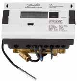
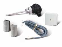
7 What role does the ECL Comfort play? The ECL Comfort is an electronic controller for weather compensation. By fitting typical applications for district heating, cooling and micro network systems including communication, it enables you easily to optimize system performance and operation. This leads to energy savings and longer system life. The house owners/tenants favorite For the end-user, ECL Comfort controllers are first and foremost equal to energy savings. Lower energy consumption, registered by the Sonometer connected to the ECL Comfort, and a Room temperature sensor smaller heat bill will always be popular. The comfort level is of course still the same, and operation is made easy with the single dial interface which features a modern design. Outdoor temperature sensor A correctly installed and commissioned electronic controller is the prerequisite for a stable and wellfunctioning heating system. Easy installation and an intuitive interface makes sure that the ECL Comfort controller is always installed correctly for the maximum benefit. ECA Remote Controller Motorized control valves ECL Comfort controller Energy meter Network Communication facilities System temperature sensor 77

8 A few steps of commissioning that put you... Countless advantages For successful commissioning of the ECL Comfort controller only a few steps are required. It is very straightforward, and in fact you don't need any special programming knowledge. Elegant no-fuss user interface Intuitive software makes operation a breeze Instant feedback displayed in your own language Access to user data, alarms, logs and settings User-friendly technical documentation Setup wizard Language selection After wiring and connecting system components, such as pumps, actuators and temperature sensors, you can insert the ECL Application Key. Use the turn/push dial to select your preferred language and follow the setup progress on the display. Setup wizard Application selection Select your application from the system application range included on the ECL Application Key. You can choose from applicationspecific factory settings or user-specific settings if they have been stored on the key. The key to easy installation The ECL Comfort controller is matched with a full range of ECL Application Keys. Each Application Key is programmed with specific parameters for a particular district heating or cooling application. The ingenious ECL Application Key makes it easier than ever to install and set up your heating system appli- cation in the ECL controller, all without any need for advanced programming. This makes it easy to manage and adjust your application settings. In the event of malfunction in the heating system the application parameters won't be affected by e.g. power failure since they are stored in the controller. Besides the data logging facility in the ECL controller facilitates troubleshooting and keeps system maintenance at a minimum. The Application Key also facilitates copying of settings to other ECL controllers in the system. This makes it easy to adjust settings and helps ensure smooth operation and energy optimisation for years to come. 8

9 ...one step ahead of schedule Main controller settings The main control parameters should be configured for optimum commissioning. They are located in the settings menu. Room heating and DHW flow temperatures are set in the user menus. Heating curve With six configurable coordinates for the flexible heating curve, the ECL Comfort 210/310 controller meets all requirements for achieving an accurate comfort temperature level in the system. Favorite display Select your favorite display from a set of pre-defined displays in order to get a quick system overview. Using your favorite display, you can perform functions such as selecting the controller mode (scheduled, comfort, saving or frost protection mode) and desired comfort temperature level (room and DHW). One key 100% application expertise The data programmed in every ECL Application Key incorporates dedicated and applied expertise from worldwide experience with district heating applications. This is your best guarantee for optimum system performance. No unplanned service visits With correct commissioning, the lasting durability of ECL leads to full customer satisfaction and no unplanned service visits. 99


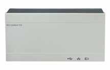
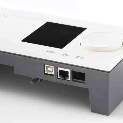
10 ECL COMFORT 210 ECL COMFORT 310 Stand-alone controller for multiple heating and cooling applications with up to 2 circuits 2 control circuits + thermostatic function Intelligent ECL Application Keys, series A2xx Turn/push dial navigation Large graphical display with backlight More room for cabling Cable box and user interface can be separated Two 3-point control outputs optimised for actuators 8 inputs: 6 Pt 1000, 2 configurable 4 relay outputs Data logging readout on display or via USB interface USB port for service Modbus R85 for short cable distances Master/slave option Optimised for substations and operation in a system using actuators, control valves, Pt 1000 sensors and pressure transmitters Controller with communication interfaces for applications with up to 3 circuits In addition to the features of the ECL Comfort 210, the ECL Comfort 310 gives you: 3 control circuits + thermostatic function Integrated communication interfaces: USB interface for service Modbus R85 for longer distances M-bus master dedicated for heat meters Modbus TCP 10 input: 6 Pt 1000, 4 configurable Three 3-point control output optimised for actuators 6 relay outputs Data logging readout on display or via communication interface Connection to ECL Portal - easy to install and access ECL 210 summary: Basic requirements, high performance in district heating systems. summary: For high requirements with communication and extension options, without programming. 10 ECA Remote controller Remote Control Unit (RCU): In case of limited access to the basement or heating system, the ECL Comfort controller can be supplemented with a remote control unit, ECA 30/31, which can be placed at any desired location in the building. This enables room temperature monitoring and control, easy interfacing, and remote access for overriding all the functions of the ECL Comfort controller.
11 Select ECL Comfort for your application ECL COMFORT ECL 110 ECL 210 ECL 310 Application ECL Application and system type Key designation Circuit types Heating 116 DH 130 DH A214 DH/DC (Vent) A217 DH A230 DH/DC A231 DH A232 DH/DC A237 DH A247 DH A260 DH A266 DH A275 BOILER A333 DH A361 DH A367 DH A368 DH A376 DH A377 DH A390 DH Cooling 1) 1) Domestic hot water (DHW) DHW Storage with internal heat exchanger Storage with charging DHW control with HEX 1) 1) Legend for ECL Application Key designation: A = Application Key 2 = Suitable for ECL Comfort 210 and = Only suitable for ECL Comfort 310 xx = Specific application type Abbreviations: DH (district heating); DC (district cooling) 1) = Either heating or cooling Notes: ECL Comfort 310 extension options ECL accessories and temperature sensors For applications with extended requirement the addi- Base part for mounting on wall or DIN rail Temperature sensors (Pt 1000) Outdoor and room Pipe surface and immersion tional internal I/O extension module ECA 32 is available. For refill water and two pump function For analog (0-10 V) control of motorized control valves, dampers and rotating heat exchangers Extra signal inputs For analog (0-10 V) control of circulation pump speed 1111
12 Index for applications keys ECL Comfort 110 Application Description Page 116 Electronic temperature control of DHW circuits Electronic temperature controller for weather compensated flow temperature control of directly or indirectly connected heating systems 16 ECL Comfort 210 ECL Comfort 310 Application Description Page A214 A214 also covering A314: Multi purpose application. Temperature control of, for example, ventilation systems with heating or cooling or a combination of these. Weather based compensation, return temperature (A314) limitation, frost and fire protection. Optional analog control of cross-flow or rotary heat exchanger. Alarm function related to duct / flow temperature, fire and frost. A217 A217 also covering A317: Advanced temperature control of DHW circuit with storage tank, directly heated or charging system. Return temperature limitation. Optional temperature control of DHW heating (A317) temperature. Alarm function related to flow temperature A230.1 Heating A230.2 Cooling Weather compensated control of flow temperature in a heating circuit. Room temperature and wind speed compensation. Sliding return temperature limitation. Alarm function related to flow temperature. Control of flow temperature in a cooling circuit. Room and weather compensation. Return temperature limitation. 35 A231 A231 also covering A331: Weather compensated control of flow temperature in a heating circuit. Sliding return temperature limitation. Control of one or two circulation pumps. Optional control of flow (A331) temperature related to supply temperature. Refill water function. Alarm function related to flow temperature, pressure and circulation pumps operation. Additional function in A331: Control of one or two pumps for refill water function. A232 A232 also covering A332: Weather compensated flow temperature control of heating / cooling circuit(s). Automatic (A332) change-over between heating and cooling. Circulation pump control. Dew point (cooling mode only) and surface temperature compensation. Return temperature limitation. A237 A237 also covering A337: Weather compensated control of flow temperature in heating circuit. Room temperature compensation and sliding return temperature limitation. (A337) Temperature control in DHW circuit with storage tank, directly heated or charging system. Return temperature limitation. Possibility for DHW priority. Alarm function related to flow temperatures. A247 A247 also covering A347: Weather compensated control of flow temperature in heating circuit. Room temperature compensation and sliding return temperature limitation. (A347) Temperature control in DHW circuit with storage tank, directly heated or charging system. Return temperature limitation. Possibility for sliding DHW priority. Alarm function related to flow temperatures A260 A266 Weather compensated control of flow temperature in two heating circuits. Room temperature compensation and sliding return temperature limitation. Circuits independent in parallel or circuit 2 after circuit 1. Alarm function related to flow temperatures. Weather compensated control of flow temperature in heating circuit. Room temperature compensation and sliding return temperature limitation. Flow temperature control in DHW circuit. Return temperature limitation. Sliding DHW priority possibility. Optional DHW temperature control related to DHW flow detection. Alarm function related to flow temperatures A275 A275 also covering A375: Weather compensated flow temperature control of 1-stage boiler based heating systems. One direct heating circuit and one mixing circuit. Circulation pumps control, room temperature control and sliding return temperature limitation. (A375) Temperature control of DHW storage tank with internal heat exchanger. Frost protection and alarm function. The A275 application key contains applications related to ECL Comfort 310 for increased functionalities (multiple boiler stages). 57 A333 Weather compensated control of flow temperature in heating circuit. Sliding return temperature limitation. Control of one or two circulation pumps. Refill water function for one or two pumps and refill water storage control. Pressure and temperature monitoring functions. Alarm function related to flow temperature, pressure and circulation pumps operation
13 ECL Comfort 210 ECL Comfort 310 Application Description Page A361 A367 A368 A376 A377 A390 Weather compensated control of flow temperature in two heating circuits. Sliding return temperature limitation. Control of one or two circulation pumps in each heating circuit. Optional control of flow temperature related to supply temperature. Refill water function. Alarm function related to flow temperature, pressure and circulation pumps operation. Weather compensated control of flow temperature in two heating circuits. Room temperature compensation and sliding return temperature limitation. Heating circuits work independent in parallel or circuit 2 after circuit 1. Temperature control in DHW circuit with storage tank, directly heated or charging system. Return temperature limitation. DHW priority. Alarm function related to flow temperatures. Weather compensated control of flow temperature in heating circuit. Sliding return temperature limitation. Control of one or two circulation pumps. Optional control of flow temperature related to supply temperature. Refill water function for one or two pumps. Flow temperature control in DHW circuit. Return temperature limitation. Sliding DHW priority possibility. Control of one or two circulation pumps. Alarm function related to flow temperature, pressure and circulation pumps operation. Weather compensated control of flow temperature in two heating circuits. Room temperature compensation and sliding return temperature limitation. Heating circuits work independent in parallel or circuit 2 after circuit 1. Flow temperature control in DHW circuit. Return temperature limitation. Sliding DHW priority possibility. Optional DHW temperature control related to DHW flow detection. Alarm functions related to flow temperatures, pressures and extra alarm input. Optional control of motorized control valves by means of analog signal (0-10 volt). Weather compensated control of flow temperature in two heating circuits. Room temperature compensation and sliding return temperature limitation. Heating circuits work independent in parallel or circuit 2 after circuit 1. Temperature control in DHW circuit with storage tank, directly heated or charging system. Return temperature limitation. DHW priority. Optional temperature control of DHW heating temperature. Alarm function related to flow temperatures. Weather compensated control of flow temperature in up to three heating circuits. Room tem perature compensation and sliding return temperature limitation. Heating circuits work independent in parallel or circuit 2 and 3 after circuit 1. Control of flow temperature in up to three cooling circuits. Room tem perature compensation and return temperature limitation. Cooling circuits work independent in parallel or circuit 2 and 3 after circuit 1. Temperature control of DHW tank charging circuit. Control of DHW heating temperature. Return temperature limitation. DHW priority possibility. Alarm functions related to flow temperatures. Optional control of motorized control valves by means of analog signal, 0-10 volt, (3 x heating circuits only)
14 ECL Comfort 110 Application 116 Electronic temperature control of DHW circuits. 116 Constant DHW temperature control with heat exchanger. 116 Constant temperature control of DHW circuit with storage tank with built-in heating coil. 14
15 116 87H Example c DHW temperature control at DHW tapping (DHW draw-off) detected by flow switch (FS). FS H Example d DHW temperature control at DHW tapping (DHW draw-off) detected by flow switch (FS) (DHW circulation). FS 15 15
16 ECL Comfort 110 Application 130 Electronic temperature controller for weather compensated flow temperature. 130 District heating circuit with heat exchanger (indirect connected heating circuit). 130 Direct connected district heating circuit Example c Boiler based heating circuit.
17 ECL Comfort 210/310 Application A214/A314 Multi purpose application. Temperature control of, for example, ventilation systems with heating or cooling or a combination of these. Weather based compensation, return temperature limitation, frost and fire protection. Optional analog control of cross-flow or rotary heat exchanger. Alarm function related to duct / flow temperature, fire and frost. A214.1 ECL 210 / H Ventilation system with cooling and constant room temperature control. X3 F1 A214.1 ECL 210 / H F1 Ventilation system with cooling and constant room temperature control. Chiller has constant flow. X3 A214.1 ECL 210 / H F1 F1 Example c Ventilation system (fan coils) with cooling and constant room temperature control. X
18 ECL Comfort 210/310 Application A214/A314 Multi purpose application. Temperature control of, for example, ventilation systems with heating or cooling or a combination of these. Weather based compensation, return temperature limitation, frost and fire protection. Optional analog control of cross-flow or rotary heat exchanger. Alarm function related to duct / flow temperature, fire and frost. A214.1 ECL 210 / H Example d Cooling system with constant flow temperature control. F1 A214.1 ECL 210 / H Example e Cooling system in ceiling and constant room temperature control in for example a wine cellar. F1 A214.2 ECL 210 / H X3 F1 18 Ventilation system with heating and constant duct temperature control.
19 A214.2 ECL 210 / H Heating of a swimming pool, constant water temperature control. F1 A214.3 ECL 210 / H X3 Ventilation system with heating and constant room temperature control. F1 A214.3 ECL 210 / H F1 F1 Ventilation system (fan coils) with heating and constant room temperature control. X
20 ECL Comfort 210/310 Application A214/A314 Multi purpose application. Temperature control of, for example, ventilation systems with heating or cooling or a combination of these. Weather based compensation, return temperature limitation, frost and fire protection. Optional analog control of cross-flow or rotary heat exchanger. Alarm function related to duct / flow temperature, fire and frost. A214.4 ECL 210 / H X3 Ventilation system with heating, cooling and constant duct temperature control. F1 A214.4 ECL 210 / H X3 Ventilation system with heating, passive cooling (outside air) and constant duct temperature control. F1 20
21 A214.5 ECL 210 / H X3 Ventilation system with heating, cooling and constant room temperature control. F1 A214.5 ECL 210 / H X3 Ventilation system with heating, passive cooling (outside air) and constant room temperature control. F1 A214.5 ECL 210 / H X3 Example c Ventilation system with heating, crossflow heat exchanger control and constant room temperature control. F
22 ECL Comfort 210/310 Application A214/A314 Multi purpose application. Temperature control of, for example, ventilation systems with heating or cooling or a combination of these. Weather based compensation, return temperature limitation, frost and fire protection. Optional analog control of cross-flow or rotary heat exchanger. Alarm function related to duct / flow temperature, fire and frost. A214.6 Heating system with 3-port mixing valve A214.6 Heating system with heat exchanger 22
23 A ECA 32 87H X3 Ventilation system with heating, passive cooling (outside air) and constant duct temperature control. Analog controlled passive cooling (). A F1 A ECA 32 87H A X3 Ventilation system with heating, cooling and constant duct temperature control. Analog controlled cooling (). F1 A ECA 32 87H X3 Ventilation system with heating, passive cooling (outside air) and constant room temperature control. Analog controlled passive cooling (). A F
24 ECL Comfort 210/310 Application A214/A314 Multi purpose application. Temperature control of, for example, ventilation systems with heating or cooling or a combination of these. Weather based compensation, return temperature limitation, frost and fire protection. Optional analog control of cross-flow or rotary heat exchanger. Alarm function related to duct / flow temperature, fire and frost. A ECA 32 87H A X3 Ventilation system with heating, cooling and constant room temperature control. Analog controlled cooling (). F1 A ECA 32 87H X3 Ventilation system with heating and constant room temperature control. Analog controlled fan speed (V1) based on outdoor wind speed. F1 / V1 A ECA 32 V1 87H A X3 24 Ventilation system with heating and constant room temperature control. Analog controlled air curtain (V1) speed based on outdoor wind speed. F1
25 A314.4 Ventilation system with heating, passive cooling (outside air) and room temperature control. Analog controlled speed of fans in relation to pressures. Analog controlled speed of rotary heat exchanger () for heat recovery. A314.4 Ventilation system with heating, passive cooling (outside air) and room temperature control. Analog controlled speed of fans in relation to pressures. Analog controlled damper () for heat recovery by means of a cross heat exchanger. A314.4 Example c Ventilation system with heating, passive cooling (outside air) and room temperature control. Analog controlled speed of fans in relation to pressures. Analog controlled speed of rotary heat exchanger () for heat recovery. Control of Night damper P8 for reduced ventialtion during saving periods
26 ECL Comfort 210/310 Application A214/A314 Multi purpose application. Temperature control of, for example, ventilation systems with heating or cooling or a combination of these. Weather based compensation, return temperature limitation, frost and fire protection. Optional analog control of cross-flow or rotary heat exchanger. Alarm function related to duct / flow temperature, fire and frost. A314.4 Example d Ventilation system with heating, passive cooling (outside air) and room temperature control. Analog controlled speed of fans in relation to pressures. Analog controlled damper () for heat recovery by means of a cross heat exchanger. Control of Night damper P8 for reduced ventilation during saving periods. A314.4 Example e Ventilation system with heating, passive cooling (outside air) and room temperature control. Analog controlled speed of fans in relation to pressures. Analog controlled valve () for heat recovery by means of a Fluid battery. Control of Night damper P8 for reduced ventilation during saving periods. 26 A314.5 Ventilation system with heating, passive cooling (outside air) and room temperature control. Analog controlled speed of fans in re lation to air quality (CO2). Analog controlled speed of rotary heat exchanger () for heat recovery.
27 A314.5 Ventilation system with heating, passive cooling (outside air) and room temperature control. Analog controlled speed of fans in re lation to air quality (CO2). Analog controlled damper () for heat recovery by means of a cross heat exchanger. A314.5 Example c Ventilation system with heating, passive cooling (outside air) and room temperature control. Analog controlled speed of fans in re lation to air quality (CO2). Analog controlled speed of rotary heat exchanger () for heat recovery. Control of Night damper P8 for reduced ventilation during saving periods. A314.5 Example d Ventilation system with heating, passive cooling (outside air) and room temperature control. Analog controlled speed of fans in re lation to air quality (CO2). Analog controlled damper () for heat recovery by means of a cross heat exchanger. Control of Night damper P8 for reduced ventilation during saving periods. 2727
28 ECL Comfort 210/310 Application A214/A314 Multi purpose application. Temperature control of, for example, ventilation systems with heating or cooling or a combination of these. Weather based compensation, return temperature limitation, frost and fire protection. Optional analog control of cross-flow or rotary heat exchanger. Alarm function related to duct / flow temperature, fire and frost. A314.5 Example e Ventilation system with heating, passive cooling (outside air) and room temperature control. Analog controlled speed of fans in re lation to air quality (CO2). Analog controlled valve () for heat recovery by means of a Fluid battery. Control of Night damper P8 for reduced ventilation during saving periods. A ECA 32 X4 87H M3 Ventilation system with heating, cooling and room temperature control. Analog controlled speed of fans in relation to pressures. Analog controlled speed of rotary heat exchanger () for heat recovery. 0 X3 3 A 4 0 X5 S9 F1 / V2 F1 / V3 S9 1 2 A ECA 32 X4 87H M3 28 Ventilation system with heating, cooling and room temperature control. Analog controlled speed of fans in relation to pressures. Analog controlled damper () for heat recovery by means of a cross heat exchanger. 0 A X X5 S9 F1 / V2 F1 / V3 S9 1 2
29 A ECA 32 X4 87H M3 Example c Ventilation system with heating, cooling and room temperature control. Analog controlled speed of fans in relation to pressures. Analog controlled valve () for heat recovery by means of a Fluid battery. 0 A P7 X X5 S9 F1 / V2 F1 / V3 S9 1 2 A ECA 32 X4 87H M3 Ventilation system with heating, cooling and room temperature control. Analog con trolled speed of fans in relation to air quality (CO2). Analog controlled speed of rotary heat exchanger () for heat recovery. 0 X3 3 A 4 0 X5 S9 F1 / V2 F1 / V3 S9 1 A ECA 32 X4 87H M3 Ventilation system with heating, cooling and room temperature control. Analog con trolled speed of fans in relation to air quality (CO2). Analog controlled damper () for heat recovery by means of a cross heat exchanger. 0 A X X5 S9 F1 / V2 F1 / V3 S
30 ECL Comfort 210/310 Application A214/A314 Multi purpose application. Temperature control of, for example, ventilation systems with heating or cooling or a combination of these. Weather based compensation, return temperature limitation, frost and fire protection. Optional analog control of cross-flow or rotary heat exchanger. Alarm function related to duct / flow temperature, fire and frost. A ECA 32 X4 87H M3 Example c Ventilation system with heating, cooling and room temperature control. Analog con trolled speed of fans in relation to air quality (CO2). Analog controlled valve () for heat recovery by means of a Fluid battery. 0 A P7 X X5 S9 F1 / V2 F1 / V3 S9 1 A ECA 32 X4 87H Ventilation system with heating and room temperature control. Analog controlled speed of fans in relation to air quality (CO2). 0 A X3 S9 F1 / V2 F1 / V3 1 0 S9 A ECA 32 X4 87H Ventilation system with heating and room temperature control. Analog con trolled speed of fans in re lation to air quality (CO2). ON-OFF control of damper. 0 A X3 0 S9 F1 / V2 F1 / V3 S9 1
31 ECL Comfort 210/310 Application A217/A317 Advanced temperature control of DHW circuit with storage tank, directly heated or charging system. Return temperature limitation. Optional temperature control of DHW heating temperature. Alarm function related to flow temperature. A217.1 / A317.1 Indirectly connected DHW charging system. DHW circulation through DHW tank (A) or heat exchanger (B). A217.1 / A317.1 ECL 210 / H Indirectly connected DHW heating system. A217.1 / A317.1 ECL 210 / H Example c Directly connected DHW heating system
32 ECL Comfort 210 Application A217 Advanced temperature control of DHW circuit with storage tank, directly heated or charging system. Return temperature limitation. Optional temperature control of DHW heating temperature. Alarm function related to flow temperature. A217.1 / A317.1 ECL 210 / H Example d Directly connected DHW heating system. A217.2 / A317.2 ECL 210 / H Indirectly connected DHW charging system with controlled heating temperature. DHW circulation through DHW tank (A) or heat exchanger (B). B A A217.2 / A317.2 ECL 210 / H Indirectly connected DHW charging system with controlled heating temperature. DHW circulation through DHW tank (A) or heat exchanger (B). B A
33 A217.3 Indirectly connected DHW heating system. DHW circulation through heat exchanger. A217.3 Indirectly connected DHW heating system. DHW heating on demand via flow switch ()
34 ECL Comfort 210 Application A217 Advanced temperature control of DHW circuit with storage tank, directly heated or charging system. Return temperature limitation. Optional temperature control of DHW heating temperature. Alarm function related to flow temperature. A217.3 Example c Indirectly connected DHW heating system. DHW circulation through heat exchanger. A217.3 Example d Directly heated DHW tank. DHW circulation through DHW tank. 34
35 ECL Comfort 210/310 Application A230 Heating Application A230.1 Weather compensated control of flow temperature in a heating circuit. Room temperature and wind speed compensation. Sliding return temperature limitation. Alarm function related to flow temperature. A230.1 Indirectly connected heating system (typically district heating). A230.1 Directly connected heating system. A230.1 Example c Boiler heating system with 3 port valve
36 ECL Comfort 210/310 Application A230 Cooling Application A230.2 Control of flow temperature in a cooling circuit. Room and weather compensation. Return temperature limitation. A230.1 Example d Boiler heating system with 4 port rotary valve. A230.2 Indirectly connected cooling system (typically district cooling). A Directly connected cooling system.
37 A230.2 Example c Indirectly connected cooling system, constant flow on cooling supply side. A230.2 Example d Two circulation pumps in shifted control, controlled by schedule
38 ECL Comfort 210/310 Application A231/A331 Weather compensated control of flow temperature in a heating circuit. Sliding return temperature limitation. Control of one or two circulation pumps. Optional control of flow temperature related to supply temperature. Refill water function. Alarm function related to flow temperature, pressure and circulation pumps operation. Additional function in A331: Control of one or two pumps for refill water function. A231.1 Indirectly connected heating system with two-pump control and refill water function. A231.2 Indirectly connected heating system with two-pump control and refill water function (supply temperature measurement gives further control / limitation possibilities)
39 A331.1 Indirectly connected heating system with two-pump control and refill water function. A331.2 Indirectly connected heating system with two-pump control and refill water function (supply temperature measurement gives further control / limitation possibilities)
40 ECL Comfort 210/310 Application A232/A332 Weather compensated flow temperature control of heating / cooling circuit(s). Automatic change-over between heating and cooling. Circulation pump control. Dew point (cooling mode only) and surface temperature compensation. Return temperature limitation. A232.1 Control of flow temperature (heating in floor / cooling in ceiling) in relation to outdoor, room and dew point temperature. A232.1 Control of flow temperature (heating / cooling) in floor in relation to outdoor, room and dew point temperature. A Example c Control of flow temperature (heating / cooling) to a fan-coil in relation to outdoor, room and dew point temperature.
41 A232.1 Example d Control of flow temperature (heating / cooling) to a fan-coil in relation to outdoor, room and dew point temperature. Heating source: District heating. Cooling source: Cooling machine. A232.1 Example e Control of flow temperature (heating / cooling) in relation to outdoor, room and dew point temperature. Heating / cooling sources: District heating / district cooling. A332.1 Control of flow temperature (heating in floor / cooling in ceiling) in relation to outdoor, room and dew point temperature. Optional return temperature limitation
42 ECL Comfort 210/310 Application A232/A332 Weather compensated flow temperature control of heating / cooling circuit(s). Automatic change-over between heating and cooling. Circulation pump control. Dew point (cooling mode only) and surface temperature compensation. Return temperature limitation. A332.2 Separated control of flow temperatures for heating / cooling in relation to outdoor, room and dew point temperature. Optional return temperature limitations. A332.2 District heating / cooling based control of flow temperatures for heating / cooling in relation to outdoor, room and dew point temperature. Optional return temperature limitations. 42 A332.2 Example c Direct connected heating / cooling based control of flow temperatures for common heating / cooling circuit. Control in relation to outdoor and room temperature. Optional surface and return temperature limitations.
43 A332.2 Example d Indirect connected heating / cooling based control of flow temperatures for common heating / cooling circuit. Control in relation to outdoor and room temperature. Optional sur face and return temperature limi tations. A332.3 Separated control of flow temperatures in heating and cooling circuits. Control in relation to outdoor and / or room temperature. Optional sur face and return temperature limi tations. Indirectly connected DHW system with flow switch for DHW heating on demand
44 ECL Comfort 210/310 Application A232/A332 Weather compensated flow temperature control of heating / cooling circuit(s). Automatic change-over between heating and cooling. Circulation pump control. Dew point (cooling mode only) and surface temperature compensation. Return temperature limitation. A332.3 Separated control of flow temperatures in heating and cooling circuits. Control in relation to outdoor and / or room temperature. Optional surface and return temperature limitations. Indirectly connected DHW system with flow switch for DHW heating on demand. A332.4 S9 87H Control of flow temperature (heating in floor / cooling in ceiling) in relation to outdoor, room and dew point temperature. Optional return and surface temperature limitation. Override functionalities for heating and cooling modes. X3 X2 0 44
45 ECL Comfort 210/310 Application A237/A337 Weather compensated control of flow temperature in heating circuit. Room temperature compensation and sliding return temperature limitation. Temperature control in DHW circuit with storage tank, directly heated or charging system. Return temperature limitation. Possibility for DHW priority. Alarm function related to flow temperatures. A237.1 / A337.1 Indirectly connected system and secondarily connected DHW tank with internal heat exchanger (optional DHW priority). A237.1 / A337.1 Indirectly connected system and secondarily connected DHW tank with internal heat exchanger (DHW priority). A237.1 / A337.1 Example c Indirectly connected system and primarily connected DHW tank with internal heat exchanger (optional DHW priority)
46 ECL Comfort 210/310 Application A237/A337 Weather compensated control of flow temperature in heating circuit. Room temperature compensation and sliding return temperature limitation. Temperature control in DHW circuit with storage tank, directly heated or charging system. Return temperature limitation. Possibility for DHW priority. Alarm function related to flow temperatures. A237.1 / A337.1 Example d Directly connected system and DHW tank with internal heat exchanger (optional DHW priority). A237.2 / A337.2 Indirectly connected system and secondarily connected DHW charging system (optional DHW priority). A237.2 / A Indirectly connected system and secondarily connected DHW charging system (DHW priority).
47 ECL Comfort 210/310 Application A247/A347 Weather compensated control of flow temperature in heating circuit. Room temperature compensation and sliding return temperature limitation. Temperature control in DHW circuit with storage tank, directly heated or charging system. Return temperature limitation. Possibility for sliding DHW priority. Alarm function related to flow temperatures. A247.1 Indirectly connected heating system and DHW charging system (optional DHW priority). Room temperature can be achieved by an ECA 30. A247.1 ECL 210 / H Indirectly connected heating system and directly connected DHW tank heating system. (Pre-controlled circuit and optional DHW priority). Room temperature can be achieved by an ECA 30. A247.1 ECL 210 / H Example c Indirectly connected heating and DHW system (optional DHW priority). Room temperature can be achieved by an ECA
48 ECL Comfort 210/310 Application A247/A347 Weather compensated control of flow temperature in heating circuit. Room temperature compensation and sliding return temperature limitation. Temperature control in DHW circuit with storage tank, directly heated or charging system. Return temperature limitation. Possibility for sliding DHW priority. Alarm function related to flow temperatures. A247.2 Indirectly connected heating system and DHW tank charging system with pre-controlled charging temperature. Room temperature can be achieved by an ECA 30. A247.2 ECL 210 / H Indirectly connected heating system and DHW system. The DHW tank charging has pre-controlled charging temperature. Room temperature can be achieved by an ECA 30. B P4 A A247.2 ECL 210 / H Example c Indirectly connected heating system and DHW system. The DHW tank charging has pre-controlled charging temperature. Optional DHW priority. Room temperature can be achieved by an ECA 30. B P4 A 48
49 A247.3 Indirectly connected heating system and DHW charging system. The DHW tank charging system has controlled heating and charging temperature and optional DHW priority. Room temperature can be achieved by an ECA 30. A247.3 ECL 210 / H Indirectly connected heating and DHW charging system. The DHW tank charging has controlled heating and charging temperature and optional DHW priority. Room temperature can be achieved by an ECA 30. B P4 A A247.3 ECL 210 / H Example c Indirectly connected heating and DHW charging system. The DHW tank charging has optional DHW priority. Room temperature can be achieved by an ECA 30. B P4 A 49 49
50 ECL Comfort 210/310 Application A247/A347 Weather compensated control of flow temperature in heating circuit. Room temperature compensation and sliding return temperature limitation. Temperature control in DHW circuit with storage tank, directly heated or charging system. Return temperature limitation. Possibility for sliding DHW priority. Alarm function related to flow temperatures. A H Indirectly connected heating system and DHW charging system (optional DHW priority). B A A H Indirectly connected and controlled heating sys tem. Controlled heating temperature for DHW tank and optional DHW priority. A H Example c Indirectly connected and controlled heating sys tem. Controlled heating temperature for DHW tank and optional DHW priority. 50
51 A347.2 Indirectly connected heating system and DHW system. The DHW tank charging has direct connected and pre-controlled charging temperature. Optional DHW priority. A H Indirectly connected heating system and DHW system. The DHW tank charging has pre-controlled charging temperature. S9 B P4 A 51 51
52 ECL Comfort 210/310 Application A247/A347 Weather compensated control of flow temperature in heating circuit. Room temperature compensation and sliding return temperature limitation. Temperature control in DHW circuit with storage tank, directly heated or charging system. Return temperature limitation. Possibility for sliding DHW priority. Alarm function related to flow temperatures. A H Example c Indirectly connected heating system and DHW system. The DHW tank charging has pre-controlled charging temperature. Optional DHW priority. S9 B P4 A A H Indirectly connected heating system and DHW charging system (optional DHW priority). monitors DHW circulation return. B A 52
53 ECL Comfort 210/310 Application A260 Weather compensated control of flow temperature in two heating circuits. Room temperature compensation and sliding return temperature limitation. Circuits independent in parallel or circuit 2 after circuit 1. Alarm function related to flow temperatures. A260.1 Indirectly connected heating systems (typically district heating). Circuit 2 is floor heating. A260.1 Indirectly connected heating systems (typically district heating). is pulse based flow or energy meter. A260.1 Example c Indirectly connected heating systems (typically district heating). is pulse based flow or energy meter
54 ECL Comfort 210/310 Application A260 Weather compensated control of flow temperature in two heating circuits. Room temperature compensation and sliding return temperature limitation. Circuits independent in parallel or circuit 2 after circuit 1. Alarm function related to flow temperatures. A260.1 Example d Indirectly connected heating systems (typically district heating). Circuit 2 (as sub-circuit) is floor heating. A260.1 Example e Directly connected heating systems (boiler-based). Circuit 2 is floor heating. A Example f Directly connected heating systems (boiler-based).
55 ECL Comfort 210/310 Application A266 Weather compensated control of flow temperature in heating circuit. Room temperature compensation and sliding return temperature limitation. Flow temperature control in DHW circuit. Return temperature limitation. Sliding DHW priority possibility. Optional DHW temperature control related to DHW flow detection. Alarm function related to flow temperatures. A266.1 Indirectly connected heating and DHW system (typically district heating). is pulse based flow or energy meter. A266.1 Directly connected heating and indirectly connected DHW system. is pulse based flow or energy meter. A266.1 ECL 210 / H Example c Indirectly connected heating system and directly connected DHW tank heating. is pulse based flow or energy meter
56 ECL Comfort 210/310 Application A266 Weather compensated control of flow temperature in heating circuit. Room temperature compensation and sliding return temperature limitation. Flow temperature control in DHW circuit. Return temperature limitation. Sliding DHW priority possibility. Optional DHW temperature control related to DHW flow detection. Alarm function related to flow temperatures. A266.2 Indirectly connected heating and DHW system with flow switch. is pulse based flow or energy meter A266.9 Indirectly connected heating and DHW system with pressure transmitter and universal alarm switch. A Indirectly connected heating and DHW system. Secondary side return temperatures monitoring and universal alarm switch. is pulse based flow or energy meter. Flow / energy limitation is optional. 56
57 ECL Comfort 210/310 Application A275/A375 Weather compensated flow temperature control of 1-stage boiler based heating systems. One direct heating circuit and one mixing circuit. Circulation pumps control, room temperature control and sliding return temperature limitation. Temperature control of DHW storage tank with internal heat exchanger. Frost protection and alarm function. The A275 application key contains applications related to ECL Comfort 310 for increased functionalities (multiple boiler stages). A275.1 ECL 210 / H Boiler ON / OFF control for a heating circuit. * = Automatic by-pass valve. B1 * 1 A275.1 ECL 210 / H Boiler ON/OFF control for a heating circuit. The boiler circuit is equipped with a low loss header. * = Automatic by-pass valve. B1 * 1 A275.2 ECL 210 / H * 1 Boiler ON / OFF control for a heating and a DHW circuit. Optional DHW priority. * = Automatic by-pass valve. B
58 ECL Comfort 210/310 Application A275/A375 Weather compensated flow temperature control of 1-stage boiler based heating systems. One direct heating circuit and one mixing circuit. Circulation pumps control, room temperature control and sliding return temperature limitation. Temperature control of DHW storage tank with internal heat exchanger. Frost protection and alarm function. The A275 application key contains applications related to ECL Comfort 310 for increased functionalities (multiple boiler stages). A275.2 ECL 210 / H * 1 B1 Boiler ON / OFF control for a heating and a DHW circuit. DHW priority. * = Automatic by-pass valve. / 2 A275.2 ECL 210 / H Example c Boiler ON / OFF control for a heating and a DHW circuit. Optional DHW priority. The boiler circuit is equipped with a low loss header. * = Automatic by-pass valve. B1 * 1 2 A275.2 ECL 210 / H Example d Boiler ON / OFF control for a heating and a DHW circuit. DHW priority. The boiler circuit is equipped with a low loss header. * = Automatic by-pass valve. B1 / * 1 2
59 A275.3 ECL 210 / H P4 1 I Boiler ON / OFF control for a direct heating circuit (1), a mixing circuit (2) and a DHW circuit (3). Optional DHW priority. * = Automatic by-pass valve. B1 * 2 3 A275.3 ECL 210 / H P4 1 Boiler ON / OFF control for a direct heating circuit (1), a mixing circuit (2) and a DHW circuit (3). Partly DHW priority. * = Automatic by-pass valve. B1 / * 2 3 A275.3 ECL 210 / H P4 1 Example c Boiler ON / OFF control for a direct heating circuit (1), a mixing circuit (2) and a DHW circuit (3). DHW priority. * = Automatic by-pass valve. B1 / *
60 ECL Comfort 210/310 Application A275/A375 Weather compensated flow temperature control of 1-stage boiler based heating systems. One direct heating circuit and one mixing circuit. Circulation pumps control, room temperature control and sliding return temperature limitation. Temperature control of DHW storage tank with internal heat exchanger. Frost protection and alarm function. The A275 application key contains applications related to ECL Comfort 310 for increased functionalities (multiple boiler stages). A275.3 ECL 210 / H P4 1 Example d Boiler ON / OFF control for a direct heating circuit (1), a mixing circuit (2) and a DHW circuit (3). Optional DHW priority. The mixing circuit (2) is controlled by means of a 4-port mixing valve. * = Automatic by-pass valve. B1 * 2 3 A275.3 ECL 210 / H P4 1 Example e Boiler ON / OFF control for a direct heating circuit (1), a mixing circuit (2) and a DHW circuit (3). Optional DHW priority. The boiler circuit is equipped with a low loss header. * = Automatic by-pass valve. B1 * 2 3 A275.3 ECL 210 / H P Example f Boiler ON / OFF control, a mixing circuit control and a DHW circuit control. Optional DHW priority. * = Automatic by-pass valve. B1 2
61 A275.3 ECL 210 / H P4 1 Example g Boiler ON / OFF control for a direct heating circuit (1) and a mixing circuit (2). * = Automatic by-pass valve. B1 * 2 A H One boiler with 2 x burner ON / OFF control for a heating circuit. * = Automatic by-pass valve. B2 B1 * 1 A H x boiler ON / OFF control for a heating circuit. * = Automatic by-pass valve. B1 B2 *
62 ECL Comfort 210/310 Application A275/A375 Weather compensated flow temperature control of 1-stage boiler based heating systems. One direct heating circuit and one mixing circuit. Circulation pumps control, room temperature control and sliding return temperature limitation. Temperature control of DHW storage tank with internal heat exchanger. Frost protection and alarm function. The A275 application key contains applications related to ECL Comfort 310 for increased functionalities (multiple boiler stages). A H Example c One boiler with 2 x burner ON / OFF control for a heating circuit. The boiler circuit is equipped with a low loss header. * = Automatic by-pass valve. B2 B1 * 1 A H Example d 2 x boiler ON / OFF control for a heating circuit. The boiler circuit is equipped with a low loss header. * = Automatic by-pass valve. B1 B2 * 1 A H Example e Two boilers with 2 x burner ON / OFF control for a heating circuit. * = Automatic by-pass valve. B2 B1 B4 B3 * 1
63 A H Example f Up to 4 x boiler ON / OFF control for a heating circuit. * = Automatic by-pass valve. B1 B4 * 1 A ECA 32 87H Example g Up to 8 x boiler ON / OFF control for a heating circuit. * = Automatic by-pass valve. B1 B8 * 1 A ECA 32 87H Example h Up to 8 x boiler ON / OFF control for a heating circuit. The first boiler (high efficiency) has highest priority. * = Automatic by-pass valve. B1 B2 B8 *
64 ECL Comfort 210/310 Application A275/A375 Weather compensated flow temperature control of 1-stage boiler based heating systems. One direct heating circuit and one mixing circuit. Circulation pumps control, room temperature control and sliding return temperature limitation. Temperature control of DHW storage tank with internal heat exchanger. Frost protection and alarm function. The A275 application key contains applications related to ECL Comfort 310 for increased functionalities (multiple boiler stages). A ECA 32 87H Example i Up to 8 x boiler ON / OFF control for a heating circuit. The first two boilers (high efficiency) have highest priority. * = Automatic by-pass valve. B1 B2 B3 B8 * 1 A ECA 32 87H B1 B8 * 1 Up to 8 x boiler ON / OFF control for a heating circuit and a DHW circuit. * = Automatic by-pass valve. P4 2 A ECA 32 87H P Up to 8 x boiler ON / OFF control for a direct heating circuit (1), a mixing circuit (2) and a DHW circuit (3). Optional DHW priority. * = Automatic by-pass valve. B1 B8 * 1 3
65 A ECA 32 87H Boiler ON / OFF or modulating control for a heating circuit. S9 measures the static pressure. * = Automatic by-pass valve. B1 V1 S9 * 1 A ECA 32 87H P4 2 S9 Boiler ON / OFF or modulating control for two heating circuits and one DHW circuit. S9 measures the static pressure. * = Automatic by-pass valve. B1 V1 * P
66 ECL Comfort 310 Application A333 Weather compensated control of flow temperature in heating circuit. Sliding return temperature limitation. Control of one or two circulation pumps. Refill water function for one or two pumps and refill water storage control. Pressure and temperature monitoring functions. Alarm function related to flow temperature, pressure and circulation pumps operation. A333.1 Indirectly connected heating system with control of two circulation pumps. Refill water function with control of two pumps. A333.2 Indirectly connected heating system with control of two circulation pumps (ON / OFF and speed control). Refill water function with control of two pumps (ON / OFF and speed control). Refill water storage control. 66 A333.3 Indirectly connected heating system with control of two circulation pumps (ON / OFF and speed control) V control of control valve. Refill water function with control of two pumps (ON / OFF and speed control). Refill water storage control.
67 ECL Comfort 310 Application A361 Weather compensated control of flow temperature in two heating circuits. Sliding return temperature limitation. Control of one or two circulation pumps in each heating circuit. Optional control of flow temperature related to supply temperature. Refill water function. Alarm function related to flow temperature, pressure and circulation pumps operation. A361.1 R6 P 87H P4 V1 P Indirectly connected heating systems with two-pump control and refill water function. V2 P5 S9 A361.2 Indirectly connected heating systems with two-pump control and refill water function (supply temperature measurement gives further control / limitation possibilities)
68 ECL Comfort 310 Application A367 Weather compensated control of flow temperature in two heating circuits. Room temperature compensation and sliding return temperature limitation. Heating circuits work independent in parallel or circuit 2 after circuit 1. Temperature control in DHW circuit with storage tank, directly heated or charging system. Return temperature limitation. DHW priority. Alarm function related to flow temperatures. A367.1 R6 87H S9 P5 Indirectly connected system with 2 heating circuits and secondarily connected DHW tank with internal heat exchanger (optional DHW priority). A367.1 R6 87H S9 P5 Indirectly connected system with 2 heating circuits and secondarily connected DHW tank with internal heat exchanger (DHW priority). / M3 A367.1 R6 87H S9 P5 68 Example c Indirectly connected system with 2 heating circuits and primarily connected DHW tank with internal heat exchanger (optional DHW priority). / M3
69 A367.1 R6 87H S9 P5 Example d Indirectly connected system with 2 heating circuits (one connected as sub circuit) and secondarily connected DHW tank with internal heat exchanger (optional DHW priority). A367.1 R6 87H S9 P5 Example e Indirectly connected system with 2 heating circuits (one connected as sub circuit) and primarily connected DHW tank with internal heat exchanger (optional DHW priority). / M
70 ECL Comfort 310 Application A367 Weather compensated control of flow temperature in two heating circuits. Room temperature compensation and sliding return temperature limitation. Heating circuits work independent in parallel or circuit 2 after circuit 1. Temperature control in DHW circuit with storage tank, directly heated or charging system. Return temperature limitation. DHW priority. Alarm function related to flow temperatures. A367.2 R6 87H () P5 () Indirectly connected system with 2 heating circuits and secondarily connected DHW charging system (optional DHW priority). S9 P4 A367.2 R6 87H () P5 () Indirectly connected system with 2 heating circuits and secondarily connected DHW charging system (DHW priority). / M3 S9 P4 A367.2 R6 87H () P5 () 70 Example c Indirectly connected system with 2 heating circuits (one connected as sub circuit) and secondarily connected DHW charging system (optional DHW priority). S9 P4
71 ECL Comfort 310 Application A368 Weather compensated control of flow temperature in heating circuit. Sliding return temperature limitation. Control of one or two circulation pumps. Optional control of flow temperature related to supply temperature. Refill water function for one or two pumps. Flow temperature control in DHW circuit. Return temperature limitation. Sliding DHW priority possibility. Control of one or two circulation pumps. Alarm function related to flow temperature, pressure and circulation pumps operation. A368.1 Indirectly connected heating and DHW system with two-pump control and refill water function. A368.2 Indirectly connected heating and DHW system with two-pump control and refill water function (supply temperature measurement gives further control / limitation possibilities). A368.3 Indirectly connected heating and DHW system with two-pump control and refill water function. Pressure measurements in the system
72 ECL Comfort 310 Application A368 Weather compensated control of flow temperature in heating circuit. Sliding return temperature limitation. Control of one or two circulation pumps. Optional control of flow temperature related to supply temperature. Refill water function for one or two pumps. Flow temperature control in DHW circuit. Return temperature limitation. Sliding DHW priority possibility. Control of one or two circulation pumps. Alarm function related to flow temperature, pressure and circulation pumps operation. A368.4 Indirectly connected heating and DHW system with two-pump control and refill water function. Supply temperature measurement gives further control / limitation possibilities. Pressure measurements in the system. A368.5 Indirectly connected heating and DHW system with two circulation pump control and refill water function with volume measurement. Monitoring of secondary return temperatures. Monitoring of pressures. A Indirectly connected heating and DHW system with two circulation pump control and refill water function. Monitoring of secondary return temperatures. Monitoring of pressure in heating circuit.
73 ECL Comfort 310 Weather compensated control of flow temperature in two heating circuits. Room temperature compensation and sliding return temperature limitation. Heating circuits work independent in parallel or circuit 2 after circuit 1. Flow temperature control in DHW circuit. Return temperature limitation. Sliding DHW priority possibility. Optional DHW temperature control related to DHW flow detection. Alarm functions related to flow temperatures, pressures and extra alarm input. Optional control of motorized control valves by means of analog signal (0-10 volt). Application A376 A H M3 0 S9 2 Indirectly connected heating and DHW system (typically district heating). 3 A H Indirectly connected heating and DHW system (typically district heating). Heating circuit 2 is connected as a sub-circuit of heating circuit 1. Alternatively, heating circuit 2 can be a floor heating circuit. M3 S A376.2 () 87H M3 0 S9 () 2 Indirectly connected heating and DHW system with flow switch ((DHW heating on demand)
74 ECL Comfort 310 Weather compensated control of flow temperature in two heating circuits. Room temperature compensation and sliding return temperature limitation. Heating circuits work independent in parallel or circuit 2 after circuit 1. Flow temperature control in DHW circuit. Return temperature limitation. Sliding DHW priority possibility. Optional DHW temperature control related to DHW flow detection. Alarm functions related to flow temperatures, pressures and extra alarm input. Optional control of motorized control valves by means of analog signal (0-10 volt). Application A376 A376.2 () 87H Indirectly connected heating and DHW system with flow switch (DHW heating on demand). Heating circuit 2 is connected as a sub-circuit of heating circuit 1. Alternatively, heating circuit 2 can be a floor heating circuit. M3 S9 0 () 2 3 A ECA 32 87H A 1 Indirectly connected heating and DHW system (typically district heating). Motorized control valves are controlled by means of analog signals (0 10 V). M3 A A 0 S9 2 3 A Indirectly connected heating and DHW system (typically district heating). Motorized control valves are controlled by means of analog signals (0 10 V). Heating circuit 2 is connected as a sub-circuit of heating circuit 1. Alternatively, heating circuit 2 can be a floor heating circuit
75 A H S9 Indirectly connected system with 1 heating circuit, 1 directly DHW heating circuit and 1 directly DHW heating circuit with flow switch (DHW heating on demand). M A376.9 Indirectly connected heating and DHW system with pressure transmitters and alarm input (typically district heating). 7575
76 ECL Comfort 310 Weather compensated control of flow temperature in two heating circuits. Room temperature compensation and sliding return temperature limitation. Heating circuits work independent in parallel or circuit 2 after circuit 1. Flow temperature control in DHW circuit. Return temperature limitation. Sliding DHW priority possibility. Optional DHW temperature control related to DHW flow detection. Alarm functions related to flow temperatures, pressures and extra alarm input. Optional control of motorized control valves by means of analog signal (0-10 volt). Application A376 A ECA H Indirectly connected heating and DHW system with pressure transmitters and alarm input (typically district heating). Heating circuit 2 is connected as a sub-circuit of heating circuit 1. Alternatively, heating circuit 2 can be a floor heating circuit. 1 2 () M3 S A Indirectly connected heating and DHW system with pressure transmitters and alarm input (typically district heating). Monitoring of secondary return temperatures. 76
77 ECL Comfort 310 Application A377 Weather compensated control of flow temperature in two heating circuits. Room temperature compensation and sliding return temperature limitation. Heating circuits work independent in parallel or circuit 2 after circuit 1. Temperature control in DHW circuit with storage tank, directly heated or charging system. Return temperature limitation. DHW priority. Optional temperature control of DHW heating temperature. Alarm function related to flow temperatures. A H M3 P5 Indirectly connected heating systems and DHW charging system (optional DHW priority). 0 S9 A B P4 A377.1 M3 87H P5 Indirectly connected heating systems and DHW charging system (optional DHW priority). Heating circuit 2 is connected as a sub-circuit of heating circuit 1. Alternatively, heating circuit 2 can be a floor heating circuit. 0 S9 A B P4 A377.1 M3 87H P5 Example c Indirectly connected heating systems and DHW charging system with preheating circuit control and optional DHW priority. Heating circuit 2 is connected as a sub-circuit of heating circuit 1. Alternatively, heating circuit 2 can be a floor heating circuit. S9 0 (S9) B P4 A 77 77
78 ECL Comfort 310 Weather compensated control of flow temperature in two heating circuits. Room temperature compensation and sliding return temperature limitation. Heating circuits work independent in parallel or circuit 2 after circuit 1. Temperature control in DHW circuit with storage tank, directly heated or charging system. Return temperature limitation. DHW priority. Optional temperature control of DHW heating temperature. Alarm function related to flow temperatures. Application A377 A H Indirectly connected heating systems and DHW charging system (optional DHW priority). Alternatively, heating circuit 2 can be a floor heating circuit. The DHW tank charging has adaptive and pre-controlled charging temperature. M3 P5 S9 0 B P4 A A377.2 M3 87H Indirectly connected heating systems and DHW charging system (optional DHW priority). Heating circuit 2 is connected as a sub-circuit of heating circuit 1. Alternatively, heating circuit 2 can be a floor heating circuit. The DHW tank charging has adaptive and pre-controlled charging temperature. S9 P5 0 B P4 A 78
79 A377.2 M3 87H P5 Example c Indirectly connected system with heating circuit and DHW tank charging circuit with pre-controlled charging temperature. Optional DHW priority. S9 0 B P4 A A H M3 P5 Indirectly connected heating systems and advanced DHW charging system (optional DHW priority). Monitoring of return temperature in DHW circulation. 0 S9 B P4 A 79 79
80 ECL Comfort 310 Application A390 Weather compensated control of flow temperature in heating circuits. Room temperature compensation and sliding return temperature limitation. Heating circuits work independent in parallel or circuit 2 / 3 after circuit 1. Optional control of motorized control valves by means of analog signal, 0-10 volt, (A390.2 only). Temperature control in DHW circuit with storage tank, directly heated or charging system. Return temperature limita tion. Optional DHW priority. Flow temperature control of 3 cooling circuits with room temperature compensation and return temperature limitation. Cooling circuits work independent in parallel or circuit 2 and 3 after circuit 1. Alarm function related to flow temperatures. A x indirectly connected heating systems. A x directly connected heating systems. A Example c 3 x indirectly connected heating systems. Two heating circuits are subcircuits.
81 A x indirectly connected heating circuits. The actuators for the control valves are controlled by means of 0-10 Volt signal A x indirectly connected cooling circuits. Cooling to the rooms can be an Air Handling Unit (AHU). A x indirectly connected cooling circuits. Two cooling circuits are sub-circuits. Cooling to the rooms can be an Air Handling Unit (AHU). 8181
82 ECL Comfort 310 A Application A390 Weather compensated control of flow temperature in heating circuits. Room temperature compensation and sliding return temperature limitation. Heating circuits work independent in parallel or circuit 2 / 3 after circuit 1. Optional control of motorized control valves by means of analog signal, 0-10 volt, (3 x heating circuits only). Temperature control in DHW circuit with storage tank, directly heated or charging system. Return temperature limita tion. Optional DHW priority. Flow temperature control of 3 cooling circuits with room temperature compensation and return temperature limitation. Cooling circuits work independent in parallel or circuit 2 and 3 after circuit 1. Alarm function related to flow temperatures. Three independent heating circuits. The heating circuits are indirectly connected. DHW charging circuit 4 is combined with circuit 1. Optional DHW priority. A Three independent heating circuits. The heating circuits are indirectly connected. DHW heating circuit 4 is combined with circuit 1. Optional DHW priority. A Example c Three independent heating circuits. The heating circuits are indirectly connected. DHW heating circuit 4 is combined with circuit 1. DHW priority
83 A Example d The heating circuits are indirectly connected. Two heating circuits are subcircuits to heating circuit 1. DHW heating circuit 4 is combined with circuit 1. DHW priority. A Example e Three independent and indirectly connected heating circuits. DHW heating circuit 4 is directly heated. A H M3 P5 Two indirectly connected heating circuits. One advanced DHW charging circuit. Optional DHW priority. S9 0 B P4 A 8383
84 ECL Comfort 310 Application A390 Weather compensated control of flow temperature in heating circuits. Room temperature compensation and sliding return temperature limitation. Heating circuits work independent in parallel or circuit 2 / 3 after circuit 1. Optional control of motorized control valves by means of analog signal, 0-10 volt, (3 x heating circuits only). Temperature control in DHW circuit with storage tank, directly heated or charging system. Return temperature limita tion. Optional DHW priority. Flow temperature control of 3 cooling circuits with room temperature compensation and return temperature limitation. Cooling circuits work independent in parallel or circuit 2 and 3 after circuit 1. Alarm function related to flow temperatures. A M3 87H P5 Two indirectly connected heating circuits. Heating circuit 2 is a sub-circuit to heating circuit 1. One advanced DHW charging circuit. Optional DHW priority. S9 0 A B P4 A Two indirectly connected heating circuits and one DHW charging circuit. Always DHW charging priority. A Two indirectly connected heating circuits and one DHW heating circuit. Always DHW heating priority
85 ECL Comfort Master/slave applications Example showing connections between ECL 210 / 310 via the ECL 485 bus. Only one outdoor temperature sensor is needed and is connected to the master. Via the ECL 485 bus the master broadcasts to other ECL 210 / 310 (slaves): - Outdoor temperature signal - Time and date - DHW heating activity Master/slave system 1 In this example the master is an A266 application. The slaves are applications A237 and A
86 Example showing ECL 210 / 310 as master, controlling the main heat supply. Outdoor temperature signal, time, date and DHW heating activity signals are broadcasted to the slaves (other ECL 210 / 310). Slaves having an address can for each circuit send its desired flow temperature to the master. The master ensures that the highest demand from the slaves is fullfilled. Each circuit in the slaves can be set to close when DHW heating activity is present in the master in order to prioritize the DHW heating. Master/slave system 2 In this example the master is an A230 application. The slaves are applications A260 and twice A
87 ECL Comfort Code numbers ECL Comfort controllers Type Designation Code no. ECL Comfort 110 Universal hardware 230 V a.c. (base part is included) 087B1261 ECL Comfort 110 Universal hardware 24 V a.c. (base part is included) 087B1251 ECL Comfort 110 w. timer program Universal hardware 230 V a.c. (base part is included) 087B1262 ECL Comfort 110 w. timer program Universal hardware 24 V a.c. (base part is included) 087B1252 ECL Comfort 210 Universal hardware 230 V a.c. (base part is not included). 087H3020 ECL Comfort 210B Universal hardware 230 V a.c. (base part is not included). Without display and dial. Requires a remote control unit, ECA 30 or ECA H3030 ECL Comfort 310 Universal hardware 230 V a.c. (base part is not included). 087H3040 ECL Comfort 310 Universal hardware 24 V a.c. (base part is not included). 087H3044 ECL Comfort 310B Universal hardware 230 V a.c. (base part is not included). Without display and dial. Requires a remote control unit, ECA 30 or ECA H3050 ECL Comfort accessories Type Designation Code no. ECL Comfort 210/210 B base part For mounting on wall or DIN rail (35 mm top hat type). 087H3220 ECL Comfort 310/310 B base part ECA 30 ECA 31 ECA 30/31 frame kit for mounting in panel front For mounting on wall or DIN rail (35 mm top hat type). ECL Comfort 210 can be mounted in an ECL Comfort 310 base part (for future upgrade). Remote control unit for ECL 210/210 B/310/310 B with integrated room temp. sensor. Possibility for connecting an external room temp. sensor (base part for mounting on wall included). Remote control unit for ECL 210/210 B/310/310 B w. integrated room temp. sensor and relative humidity sensor. Possibility for connecting an external room temp. sensor. Base part included. For mounting in a cut-out. Format 144 x 96 mm, actual cut-out 139 x 93 mm. 087H H H H3236 ECA 32 Internal I/O extension module for ECL Comfort H3202 ECA V a.c. to 24 V a.c. transformer (35 VA). 087B1156 ECA 110 Timer module for ECL Comfort 110 (code no. 087B1251 and 087B1261) 087B DLG Link Gateway. Communication between ECL Comfort 110 and Living Connect thermostats. 087H
88 ECL Comfort Code numbers ECL Comfort 110 instructions Type English Danish Swedish Finnish German Latvian Russian Lithuanian Polish Estonian B B B B B B B B B B B B B B B B B B8162 Temperature sensors for ECL Comfort controllers Type Designation Code no. ESMT Outdoor temperature sensor 084N1012 ESM-10 Room temperature sensor 087B1164 ESM-11 Pipe surface temperature sensor 087B1165 ESMB-12 Universal temperature sensor with 2.5 m cable 087B1184 ESMC Pipe surface temperature sensor 087N0011 ESMU-100 Immersion sensor, 100 mm, copper 087B1180 ESMU-250 Immersion sensor, 250 mm, copper 087B1181 ESMU-100 Immersion sensor, 100 mm, stainless steel 087B1182 ESMU-250 Immersion sensor, 250 mm, stainless steel 087B1183 Pocket 100 mm stainless steel, for ESMU-100, copper 087B1190 Pocket 250 mm stainless steel, for ESMU-250, copper 087B1191 Pocket 100 mm stainless steel, for ESMB B1192 Pocket 250 mm stainless steel, for ESMB B
89 ECL Comfort Additional accessories Differential pressure switch and Alarm pressure switches Type Differential pressure range Electrical contact type Code no. Differential pressure switch, type RT 262A 0,1-1,5 bar SPDT - silver SPDT - gold available on request 017D (silver) Alarm pressure switch BCP - SPDT - gold * Alarm pressure switch KPI 35 0,2-8 bar SPDT - silver/gold (silver) (gold) * depending on application (control, high limiter, low limiter) and pressure range Comparison ECL 110 ECL 210 Flow / energy limitation X X M-bus X TCP / IP (Internet) X 24 Volt a.c. X X Inputs, temp. sensor (Pt 1000) max. 4 max. 8 max. 10 Inputs, 0-10 V max. 2 max. 4 Inputs, digital max. 2 max. 4 Inputs, ECA 32 max. 6 (Pt 1000 / digital / 0-10 V) Pulse inputs, ECA 32 2 Outputs, 0-10 V 3 (ECA 32) Relay outputs, max Relay outputs, ECA 32 4 Integration w. Link TM DLG 89 89
90 ECL Comfort application keys and languages ECL Comfort Application keys Application type Code no. Application keys Available languages Languages A214 also covering A H3811 Bulgarian Italian A217 also covering A H3807 Croatian Latvian A H3802 Czech Lithuanian A231 also covering A H3805 Danish Polish A232 also covering A H3812 Dutch Romanian A237 also covering A H3806 English Russia A247 also covering A H3808 Estonian Serbian A H3801 Finnish Slovak A H3800 French Slovenian A275 also covering A H3814 German Spanish A H3818 Hungarian Swedish A H3804 A H3813 A368 A376 A377 A H H H H3815 Please visit and find all relevant documentation for the ECL Comfort series 90


 Longer lifetime The ECL Comfort controllers feature a unique motor protection function, which prevents instability in the")
91 High performance made easy The ECL Comfort controller is designed to function as the intelligent hub of a heating system or a district heating substation. The ECL Comfort controller is designed and developed with your needs in mind and incorporates a range of features that enable you to achieve high performance. Clever communication The ECL Comfort 310 offers stateof-the-art options for communication interfaces. The range of options, available either built-in or with extension modules, includes Modbus, M-Bus, and USB for service purposes. Automatic setup of DHW parameters With advanced ECL Auto Tuning, control parameters for domestic hot water production can be configured and optimised automatically, ensuring both higher comfort and additional energy savings. Faster installation Improved cable connectors and more space for wiring ensure fast and trouble free installation of the ECL Comfort controller in the system. Tap Water T ( C) Longer lifetime The ECL Comfort controllers feature a unique motor protection function, which prevents instability in the system, thus protecting acutators and control valves against unnecessary activity. This results in up to 25% longer lifetime of these components. Easy interaction The ECL Comfort controller has a large display with graphic text and a backlight. Supported by intuitive menu navigation, turn/push dial and the setup wizard, this makes the interaction straightforward

92 Easy, Effective, ECL Access your ECL controllers via PC or smartphone The ECL Portal application for the electronic controller ECL Comfort 310 is an easy-to-use SCADA tool for control of your district heating system. ECL Portal enables you to streamline service, commissioning and maintenance directly from your PC or smartphone, wherever you are. Increase your service levels and reduce costs with 24/7 access and control and get a complete overview of energy consumption data, temperatures and flow. The result is optimum performance and actual energy savings. Real benefits, real savings The ECL Portal allows you to: Increase long-term system performance Gain a higher level of awareness and transparency of the energy consumption Improve service level and reduce response time to alarms Do troubleshooting without having to visit the heating system Feel free to contact us or visit for further information. A/S Heating Segment DK-6430 Nordborg Denmark Tel.: heating@danfoss.com can accept no responsibility for possible errors in catalogues, brochures and other printed material. reserves the right to alter its products without notice. This also applies to products already on order provided that such alterations can be made without subsequential changes being necessary in specifications already agreed. All trademarks in this material are property of the respective companies. and the logotype are trademarks of A/S. All rights reserved. VGGUA402 Copyright Heating Segment Pravda.dk 2016
ECL Comfort 210 controller, Remote Control Units ECA 30 / 31 and Application keys Designed in Denmark
 ECL Comfort 210 controller, Remote Control Units ECA 30 / 31 and Application keys Designed in Denmark Description ECL Comfort 210 controller series The ECL Comfort 210 is an electronic weather compensated
ECL Comfort 210 controller, Remote Control Units ECA 30 / 31 and Application keys
 ECL Comfort 210 controller, Remote Control Units ECA 30 / 31 and Application keys Designed in Denmark Description ECL Comfort 210 controller series ECL 210 The ECL Comfort 210 is an electronic weather
ECL Comfort 310 controller, Remote Control Units ECA 30 / 31 and Application keys
 ECL Comfort 310 controller, Remote Control Units ECA 30 / 31 and Application keys Designed in Denmark Description ECL Comfort 310 controller series ECL 310 The ECL Comfort 310 is an electronic weather
Installation Guide. ECL Comfort 310, application A Table of Contents
 1.0 Table of Contents 1.0 Table of Contents... 1 1.1 Important safety and product information..................... 2 2.0 Installation... 5 2.1 Before you start.....................................................
Operating Guide. ECL Comfort 210 / 296 / 310, application A247 / A Table of Contents
 1.0 Table of Contents 1.0 Table of Contents... 1 1.1 Important safety and product information..................... 2 2.0 Installation... 6 2.1 Before you start.....................................................
Installation Guide. ECL Comfort 210, application A Table of Contents
 1.0 Table of Contents 1.0 Table of Contents... 1 1.1 Important safety and product information..................... 2 2.0 Installation... 4 2.1 Before you start.....................................................
ECL Comfort 110, application 116
 Operating Guide ECL Comfort 110, application 116 (valid as of software version 1.08) English version www.danfoss.com How to navigate? Adjust temperatures and values. Switch between menu lines. Select /
ECL Comfort 300 / V a.c. and 24 V a.c.
 Data sheet ECL Comfort 300 / 301 230 V a.c. and 24 V a.c. Application The ECL Comfort 300 / 301 is an electronic temperature controller which can be loaded with selected applications by means of an ECL
C37. ECL Comfort. User's Guide. Installer's Guide. ECL Comfort C37. User's Guide. Installer's Guide *VI7CE602* *087R8070* *087R8070* *VI7CE602*
 User's Guide VI.7C.E6.02 2005.09 C37 *VI7CE602* *087R8070* www.danfoss.com ECL Comfort User's Guide ECL Comfort Installer's Guide www.danfoss.com *087R8070* *VI7CE602* Mixing controller with ON / OFF controlled
P20. ECL Comfort. User's Guide. Installer's Guide. ECL Comfort P20. User's Guide. Installer's Guide *VI7BD502* *087R8014* *087R8014* *VI7BD502*
 User's Guide VI.7B.D5.02 2005.10 P20 *VI7BD502* *087R8014* www.danfoss.com ECL Comfort User's Guide ECL Comfort Installer's Guide www.danfoss.com *087R8014* *VI7BD502* Boiler controller P20 VI.7B.D5.02
ECL Comfort V a.c. and 24 V a.c.
 230 V a.c. and 24 V a.c. Description and application The controller is designed for easy installation: one cable, one connector. The controller has a customdesigned display with backlight. For a quick
ECL Comfort V a.c. and 24 V a.c.
 230 V a.c. and 24 V a.c. Description and application In heating applications the can be integrated with the Danfoss Link solution via the DLG interface for use in single-family applications. The controller
ECL Comfort V a.c. and 24 V a.c.
 Data sheet ECL Comfort 300 230 V a.c. and 24 V a.c. Application The ECL Comfort 300 is an electronic temperature controller which can be loaded with selected applications by means of an ECL Card. The ECL
The ECL Comfort 110 is a universal 1-circuit controller for use in district heating substations and district heating systems as well as boilerbased
 Data sheet ECL Comfort 110 230 V a.c. and 24 V a.c. Description and application ECL Comfort 110 The ECL Comfort 110 is a universal 1-circuit controller for use in district heating substations and district
One Product Numerous Applications Electronic Controllers for Heating, Cooling, Ventilation and Air Condition
 MAKING MODERN LIVING POSSIBLE One Product Numerous Applications Electronic ontrollers for Heating, ooling, Ventilation and Air ondition Electronic ontrollers from Danfoss: Only a Few Products for an Endless
C66. ECL Comfort. User's Guide. Installer's Guide. ECL Comfort C66. User's Guide. Installer's Guide. *vi7cc502* *087R8069* *087R8069* *vi7cc502*
 User's Guide VI.7C.C5.02 2005.09 C66 *vi7cc502* *087R8069* www.danfoss.com ECL Comfort User's Guide ECL Comfort Installer's Guide www.danfoss.com *087R8069* *vi7cc502* Mixing controller with PI controlled
C62. ECL Comfort. User's Guide. Installer's Guide. ECL Comfort C62. User's Guide. Installer's Guide *VIKME102* *087R8091* *087R8091* *VIKME102*
 User's Guide VI.KM.E1.02 2005.09 C62 *VIKME102* *087R8091* www.danfoss.com ECL Comfort User's Guide ECL Comfort Installer's Guide www.danfoss.com *087R8091* *VIKME102* Double mixing controller C62 VI.KM.E1.02
Weather compensated flow temperature control of heating and boiler systems
 Instructions ECL Comfort 110 Application 130 Weather compensated flow temperature control of heating and boiler systems User guide, Installation & Maintenance DH-SMT/DK VI.KT.G3.02 Danfoss 06/2008 How
ECL Comfort 110, application 130
 Operating Guide ECL Comfort 110, application 130 (valid as of software version 1.08) English version www.danfoss.com How to navigate? Adjust temperatures and values. Switch between menu lines. Select /
ECL Comfort 210 / 296 / 310
 User Guide ECL Comfort 210 / 296 / 310 English version www.danfoss.com Safety Note Necessary assembly, start-up, and maintenance work must be performed by qualified and authorized personnel only. 2 Danfoss
Fingertip control, optimum efficiency, total comfort and clear reporting. warmafloor.co.uk
 Fingertip control, optimum efficiency, total comfort and clear reporting warmafloor.co.uk 1 Contents Intelligent control. 3 The key to efficiency Key system features 4 and benefits 7 Touchscreen 5 Alarms
TPOne-B. Electronic Programmable Room Thermostat. Installation Guide. Danfoss Heating
 TPOne-B Electronic Programmable Room Thermostat Danfoss Heating Installation Guide TPOne is an intelligent programmable heating control made easy. TPOne includes features which are designed to save energy.
RVL471. Heating controller. G2524en. Installation Instructions. 1 Installation. 2 Commissioning
 G2524en Heating controller Installation Instructions RVL471 1 Installation 1.1 Place of installation In a dry room, e.g. the boiler room Mounting choices: In a control panel (on the inner wall or on a
RVL471 Heating and Domestic Hot Water Controller Basic Documentation
 RVL471 Heating and Domestic Hot Water Controller Basic Documentation Edition: 2.2 Controller series: C CE1P2524E 23.10.2002 Siemens Building Technologies HVAC Products 2/118 HVAC Products 23.10.2002 Contents
heat interface units A BOILER WITHOUT A FLAME
 A BOILER WITHOUT A FLAME heat interface units Communal Heat Networks A central boiler house will generate heat which is distributed through a network of pipe to each home or apartment in the building.
1 DOCUMENT REVISION CONTROL ELEMENTS... 9
 CONTENTS Contents 1 DOCUMENT REVISION... 8 2 SOFTWARE VERSION... 8 3 BASIC DESCRIPTION... 8 4 CONTROL ELEMENTS... 9 4.1 BASIC DISPLAYS...10 4.2 CONTROL KEYS...11 4.2.1 Rotary button (Press / Turn)...11
Bosch. Gas Condensing Boiler. Applications Manual. 100, 151 Combi Boiler 57, 100, 131, 151 Heating Boiler
 WARNING: Improper installation, setup, modification, operation or maintenance of the heating system can cause personal injury and property damage. Follow each appliances' instructions precisely. For assistance
G a
 G2474 74 319 0081 0 a en Installation Instructions Heating controllers RVP3... Installation Place of installation In a dry room, e.g. in the boiler room Mounting choices: Control cabinet (in the front,
Feature Summary. I. System
 I. System A. Supports up to 60 VAV HVAC Units 1. Each HVAC Unit Can Support up to 59 VAV Boxes 2. Constant Volume Units Can Be Integrated With VAV Units 3. System Can Support Over 3000 Controllers B. Fill-in
- Essay Control Functions and Benefits
 - Essay Control Functions and Benefits E 005 07/01 A hydronic heating control system performs many complex and important functions. Each of these functions provide benefits that make the system comfortable,
- Data Brochure Universal Reset Module 423
 - Data Brochure Universal Reset Module 423 D 423 08/07 1 Information Brochure Choose controls to match application Application Brochure Design your mechanical applications 2 3 Rough-in Wiring Rough-in
NEW. Innovative heating controls. Commercial boiler control systems. Control 8000 & MX25
 Innovative heating controls NEW Commercial boiler control systems Control 8000 & MX25 2 Everything perfectly under control About the Bosch Group Leading global supplier The Bosch Group is active in the
WLM3 the 3 rd generation of the OJ Waterline TM Control Systems. Industry leading intelligence, control SLIDE OJ Electronics
 WLM3 the 3 rd generation of the OJ Waterline TM Control Systems Industry leading intelligence, control and operation SLIDE 1 Designed to deliver value for all. Benefits; Reliability - Fit and Forget Flexibility
Hydronic Mechanical Panels
 Hydronic Assemblies Inc. 56 Horse Hill Rd Concord NH 2015-2016 Hydronic Mechanical Panels Contact 4805 Main St. Waitsfield, Vermont 05673 Phone : 802-583-5500 WWW.Houseneeds.com Hydronic Assemblies Inc.
- Data Brochure Universal Reset Module 422
 - Data Brochure Universal Reset Module 422 D 422 08/07 1 Information Brochure Choose controls to match application Application Brochure Design your mechanical applications 2 3 Rough-in Wiring Rough-in
OJ Waterline control system
 OJ Waterline control system THERMOSTATS FOR COMFORT HEATING AND SNOW MELTING Product presentation Mk3 It s all about Room Temperature Control! The essential main goals are: Comfort Flexibility Reliability
Master devices. Type X-AIR-ZMAS. Zone master module for up to 25 zone modules, with integral webserver and interfaces to higher-level systems
 X X testregistrierung Type Web server, also for mobile devices Zone modules Zone master module for up to 25 zone modules, with integral webserver and interfaces to higher-level systems X-AIRCONTROL zone
Qualifies for up to $ 1500 Energy Tax Credit! CONDENSING RESIDENTIAL GAS BOILERS CONTROL WITH ALL NEW, ADVANCED USER FEATURES
 CONDENSING RESIDENTIAL GAS BOILERS CONTROL WITH ALL NEW, ADVANCED USER FEATURES 5 FLOOR-STANDING AND 5 WALL-MOUNT MODELS FROM 50,000 TO 285,000 BTU/HR FIRING RATE MODULATION TO 5:1 LESS THAN 20 ppm NOx
prestige Control Application Supplement - TriMax
 prestige Control Application Supplement - TriMax L I S T E D WARNING This document is intended to be used by a factory trained and qualified heating contractor or service technician only. Read all instructions
The product segments Heating, ventilation, air conditioning. Control Products & Systems OEM.
 The product segments Heating, ventilation, air conditioning Control Products & Systems OEM www.siemens.com/buildingtechnologies-oem The right product for every application Siemens specializes in the development,
Wireless Solutions. Application Selection Guide
 Wireless Solutions Application Selection Guide THERMOSTATS ZONING AIR CLEANERS HUMIDIFIERS DEHUMIDIFIERS UV SYSTEMS VENTILATION WATER SOLUTIONS COMBUSTION RedLINK Wireless Systems TrueZONE Panel Return
Modulating clock thermostat
 EN Digital timer thermosatat Modulating clock thermostat Installation and Service Manual 123189-AB Contents 1 Preface...4 1.1 General...4 2 Location of the installation...5 2.1 Position of the regulator...5
prestige Control Application Supplement - ACVMax
 2015-10 Prestige ACVMax Control Sup 12-14-15_ACVMax_Control 12/15/15 7:36 AM Page 1 prestige Control Application Supplement - ACVMax L I S T E D WARNING This document is intended to be used by a factory
Demand-controlled Ventilation Leading edge products for demand-controlled ventilation
 Overview Demand-controlled Ventilation Leading edge products for demand-controlled ventilation Demand-controlled ventilation offers great comfort and low operating costs When the room is in use, ventilation
Heating and D.h.w. Controller RVL482 Basic Documentation
 Heating and D.h.w. Controller RVL482 Basic Documentation Edition: 1.0 Controller series: A CE1P2542en 20.05.2008 Building Technologies Siemens Switzerland Ltd Building Technologies Group International
- Data Brochure Steam Control 279
 - Data Brochure Steam Control 279 D 279 12/07 The tekmar Steam Control 279 can operate a single on-off steam boiler or an on-off steam valve using outdoor reset. The control determines the on time of the
Condensing Boiler RS100 Controller Training Program
 Condensing Boiler RS100 Controller Training Program Training Program #501102A 062311 www.rinnai.us 2009 Rinnai America Corporation Features and Benefits The RS100 connects directly to the boiler and acts
At Coster we manufacture a comprehensive range of pre confi gured modular controllers which are both easy to install and simple to programme by use
 At Coster we manufacture a comprehensive range of pre confi gured modular controllers which are both easy to install and simple to programme by use of 4 operating keys and an alphanumeric display. When
prestige Control Application Supplement WARNING
 prestige Control Application Supplement WARNING This document is intended to be used by a factory trained and qualified heating contractor or service technician only. Read all instructions within this
Control Application. Supplement - ACVMax
 prestige Control Application Supplement - ACVMax L I S T E D WARNING This document is intended to be used by a factory trained and qualified heating contractor or service technician only. Read all instructions
ECL Comfort 210/296/310, application A247/A347
 Operating Guide ECL Comfort 210/296/310, application A247/A347 1.0 Table of Contents 1.0 TableofContents...1 1.1 Importantsafetyandproductinformation... 2 2.0 Installation...6 2.1 Beforeyoustart... 6 2.2
Corrigo E. Second generation which contains all applications and languages
 revision 05 2009 Corrigo E Second generation which contains all applications and languages The controllers in the Corrigo E series are intended for applications within heating, boiler and ventilation control
L CONNECTION NETWORK Commercial Controls
 L CONNECTION NETWORK Commercial Controls SIMPLIFIED, CENTRAL CONTROL Simplified Control for Your Facility The L Connection Network not only enhances comfort and energy-efficiency throughout your facilities,
Energy-efficient heat source provides comfort in large rooms
 AIR HEATER NOZ NOZ air heater Energy-efficient heat source provides comfort in large rooms When it comes to providing large, and often high buildings, with the best possible source of efficient heating
prestige Control Application Supplement - TriMax
 prestige Control Application Supplement - TriMax L I S T E D WARNING This document is intended to be used by a factory trained and qualified heating contractor or service technician only. Read all instructions
District heating controller for two heating circuits and d.h.w. according to Siemens specifications:
 4 319 2984 0 G2384en en Installation Instructions District heating controller for two heating circuits and d.h.w. RVD240 Installation Place of installation In a dry room, e.g. in the heat exchanger room
Enhance the performance of every system
 professional controls for underfloor heating Enhance the performance of every system FLOOR HEATING HYDRONIC FLOOR HEATING ELECTRIC HVAC CONTROLS & POWER OJ Waterline 3 RD GENERATION WATERBASED UNDERFLOOR
Solar controllers Energy under control
 www.seltron.eu 2015 PROMATIC SGC Solar controllers Energy under control For domestic hot water. 14 PROMATIC SGC Solar controllers 15 PROMATIC SGC Solar controllers HIGHLIGHTS ycontrol of up to 65 different
96% AFUE Efficiency CONDENSING RESIDENTIAL GAS BOILERS CONTROL WITH ADVANCED USER FEATURES MODELS FROM 80,000 TO 285,000 BTU/HR
 CONDENSING RESIDENTIAL GAS BOILERS CONTROL WITH ADVANCED USER FEATURES MODELS FROM 80,000 TO 285,000 BTU/HR 5:1 FIRING RATE MODULATION LESS THAN 20 ppm NOx DIRECT VENT FLEXIBILITY TO 100 FEET 96% AFUE
CM707. Programmable Room Thermostat with Optimum Start, Optimum Stop and Delayed Start. User Guide
 CM707 Programmable Room Thermostat with Optimum Start, Optimum Stop and Delayed Start User Guide WHAT IS A PROGRAMMABLE ROOM THERMOSTAT? An explanation for householders... A programmable room thermostat
EXcon zone control. Control for up to 4 individual zones _ fm. EXHAUSTO A/S Odensevej 76 DK-5550 Langeskov
 3005925_2018-02-05.fm EXcon zone control Control for up to 4 individual zones EXHAUSTO A/S Odensevej 76 DK-5550 Langeskov Tel. +45 65 66 12 34 Fax +45 65 66 11 10 exhausto@exhausto.dk www.exhausto.dk OJ-Air2
Parameter guide 95M-200 GAS-FIRED DIRECT VENT MODULATING HOT WATER BOILER WARNING WARNING
 95M-200 GAS-FIRED DIRECT VENT MODULATING HOT WATER BOILER! WARNING Revise boiler control parameters only if you fully understand the purpose and result of the changes and on the advice of ECR Technical
CM907- TRV PROGRAMMABLE THERMOSTAT FEATURES PRODUCT SPECIFICATION SHEET
 CM907- TRV PROGRAMMABLE THERMOSTAT PRODUCT SPECIFICATION SHEET FEATURES Attractive, slim, ultra-modern styling makes it ideal for location in any type of home. 7-day heating program. A dynamic text display
30 radiators from one central point. Simply smarter heating. living.danfoss.com. living by Danfoss heating control
 living by Danfoss heating control Simply smarter heating Giving your customers the ultimate integrated heating experience has never been easier. With Danfoss Link each individual element, from floor heating
ProCon 16, 31, 47 & 75. RVA 63 Boiler and Circuit Controller Commissioning Data.
 ProCon 16, 31, 47 & 75. RVA 63 Boiler and Circuit Controller Commissioning Data. The RVA63 controller can be utilized to control the following system configurations via LPB communication. Equipment Required
Hydronic & HVAC Control Systems
 tekmar 218 Full Line Catalog Hydronic & HVAC Control Systems HVAC Multi-Staging Alternative Energy Zoning Snow Melting Setpoint tekmarcontrols.com tekmarcontrols.com Better Design, Better Control, Better
Better Design, Better Control, Better Systems.
 Product Catalog Better Design, Better Control, Better Systems. At tekmar Control Systems, we believe the indoor comfort of a building depends on the performance of its heating, ventilating & air conditioning
AirTrak. Digital Control System. User Manual. Touchscreen Systems
 AirTrak Digital Control System User Manual Touchscreen Systems Rev. 10-29-15 1 2 Table of Contents OVERVIEW... 8 NETWORKING... 9 AIRTRAK DEFAULT SETTINGS... 9 Unit Operating Modes... 10 MRT Controls...
CM921 - User Guide 1 day Wireless Programmable Room Thermostat with LoT technology
 Description The Honeywell CM921 is a wireless programmable room thermostat designed to control you heating system efficiently, providing comfortable temperatures when you are at home and energy savings
- Data Brochure Boiler Control 274
 - Data Brochure Boiler Control 274 274_D 03/17 The Boiler Control 274 operates up to four on/off boilers to provide outdoor reset operation, domestic hot water and setpoint operation with priority. When
RVD120, RVD140 Controllers for district heating and d.h.w. Basic Documentation
 RVD120, RVD140 Controllers for district heating and d.h.w. Basic Documentation Edition 2.0 Controller series A, C CE1P2510en 2018-04-30 Building echnologies Published by: Siemens Switzerland Ltd. Building
RVP331. Heating Controller for 2 heating circuits, d.h.w. and boiler. Building Technologies HVAC Products
 2 478 Heating Controller for 2 heating circuits, d.h.w. and boiler RVP331 Multi-functional heating controller for use in residential and non-residential buildings Suitable for weather-compensated flow
DHW / Setpoint Demand WWSD Modulation Boiler Output (x10,000 BTU/hr) External Input Signal Offset / Priority Override
 External Input Signal Offset / Priority Override") Date Code - Data rochure oiler Control 265 D 265 10/03 The tekmar oiler Control 265 can control the supply water temperature on up to three modulating boilers based on outdoor temperature or setpoint requirements.
Date Code - Data rochure oiler Control 265 D 265 10/03 The tekmar oiler Control 265 can control the supply water temperature on up to three modulating boilers based on outdoor temperature or setpoint requirements.
CM901 PROGRAMMABLE THERMOSTAT FEATURES PRODUCT SPECIFICATION SHEET
 CM90 PROGRAMMABLE THERMOSTAT PRODUCT SPECIFICATION SHEET FEATURES Attractive, slim, ultra-modern styling makes it ideal for location in any type of home. 24 hour heating program. A dynamic text display
Control Products & Systems OEM
 LMS The modular management system for condensing boilers Control Products & Systems OEM www.siemens.com/buildingtechnologies-oem LMS advanced electronics and proven software At times of dwindling resources,
ProCon 16, 31, 47, 75, 77 & HT. RVA 46. Zone Controller Commissioning Data.
 ProCon 16, 31, 47, 75, 77 & HT. RVA 46. Zone Controller Commissioning Data. The RVA 46 Zone Controller can only be used in conjunction with a RVA47 controlled boiler installation. The RVA46 controller
KEMPER ThermoSystem. For further information on KTS use the QR code!
 KEMPER ThermoSystem Heating water hygienically and energy-efficiently with patented cascade rotation for automated operating change among all heating modules For further information on KTS use the QR code!
> HGA AIR - WATER HEAT PUMPS FOR OUTDOOR INSTALLATION. Available range. Unit description. Options. Accessories
 > HGA AIR - WATER HEAT PUMPS FOR OUTDOOR INSTALLATION Available range Unit type IP Reversible heat pump (reversible on the refrigerant side) ECO-FRIENDLY REFRIGERANT GAS Versions (heat recovery) VB Base
Underfloor Heating and Cooling Controls RELIABLE, ENERGY EFFICIENT CONTROLS FEATURING UNIQUE
 Underfloor Heating and Cooling Controls RELIABLE, ENERGY EFFICIENT CONTROLS FEATURING UNIQUE 110763_UPONOR_CONTROLS_BROCHURE_AW.indd 1 7/8/2013 12:04:56 AM Indoor Climate: Controls Auto Balance Technology
Heating Controller for 2 heating circuits, d.h.w. and boiler, communicating
 2 477 Heating Controller for 2 heating circuits, dhw and boiler, communicating RVP330 Multi-functional heating controller for use in residential and non-residential buildings Suitable for weather-compensated
PROMATIC WDC Heating controllers Energy under control
 www.seltron.eu 205 PROMATIC WDC Heating controllers Energy under control 36 Made for warmth. PROMATIC WDC Heating controllers 37 PROMATIC WDC Heating controllers HIGHLIGHTS ycontrol of up to 52 different
Installation and servicing instructions
 Installation and servicing instructions Programming unit RC35 For qualified professionals Please read carefully prior to commissioning and servicing 7 747 006 341-12/2006 GB Contents Contents Contents
Heating Control Danfoss Link & Connect Thermostats
 Heating Control Danfoss Link & Connect Thermostats www.heating.danfoss.com Table of Contents 1. Introduction 1.1 Segment... 3 1.2 Danfoss Eco programmable radiator thermostat... 3 1.3 Overview of units
30% Take lead on your project with an efficient system concept. lower energy.
 Technical handbook Danfoss EvoFlat systems from A-Z Take lead on your project with an efficient system concept 30% lower energy consumption by individual metering in each apartment www.evoflat.danfoss.com
ECO AND DATE /06 ARTWORK DESCRIPTION. 22 page A6 : Saddle stitch (2-wire) 6 page : 4 colour : 170gsm Silk 18 page : 1 colour : 100gsm Silk
 6 page : 4 colour : 170gsm Silk 18 page : 1 colour : 100gsm Silk") DRAWING DETAILS PART NUMBER 42011077-103 ISS R1 ECO AND DATE 0024168 08/06 ARTWORK DESCRIPTION CM921 USER GUIDE BOOKLET (UK - English) DRAWN MKTING MF BM DATE 08/06 BOOKLET DETAILS SPECIFICATION COVER
DRAWING DETAILS PART NUMBER 42011077-103 ISS R1 ECO AND DATE 0024168 08/06 ARTWORK DESCRIPTION CM921 USER GUIDE BOOKLET (UK - English) DRAWN MKTING MF BM DATE 08/06 BOOKLET DETAILS SPECIFICATION COVER
PROGRAMMABLE 7-DAY THERMOSTAT
 PROGRAMMABLE 7-DAY THERMOSTAT Installation and user instruction This instructions to be retained by the user 1 Thank you for choosing Riello s weekly programmer.. This central heating control device is
HMC300. Control unit. Operating Instructions. EMS plus (2014/10) O
 O") HMC300 Control unit EMS plus 6 720 808 471-00.1O Operating Instructions 6 720 813 192 (2014/10) Contents Contents Key to symbols and safety instructions................3 1.1 Key to symbols...........................
HMC300 Control unit EMS plus 6 720 808 471-00.1O Operating Instructions 6 720 813 192 (2014/10) Contents Contents Key to symbols and safety instructions................3 1.1 Key to symbols...........................
CS027 User Instructions
 CS027 User Instructions Battery Powered 7 Day Programmable Room Thermostat Programmable room thermostats are widely recognised as one of the best ways in which to control central heating. The CS027 programmable
AUTO CM CM USER GUIDE
 1 2 3 4 5 6 7 AUTO CM701...2-6 CM707...7-11 USER GUIDE CM701 - USER GUIDE Description The Honeywell CM701 is a programmable room thermostat designed to control your heating system efficiently, providing
Greenstar The World's Best Selling Condensing Boiler System
 Greenstar The World's Best Selling Condensing Boiler System Simply Smart Residential space and water heating boiler solutions with 95% Annual Fuel Usage Efficiency Rating (AFUE) completed by Bosch Zoning
STEAM STERILIZER SERIE S1000 (RBE)
") STEAM STERILIZER SERIE S1000 (RBE) INTRODUCTION: Of Turkish manufacturing, our sterilizers Series S1000 (RBE) are designed for the purpose of inactivating and sterilizing infectious waste generated in
STEAM STERILIZER SERIE S1000 (RBE) INTRODUCTION: Of Turkish manufacturing, our sterilizers Series S1000 (RBE) are designed for the purpose of inactivating and sterilizing infectious waste generated in
RVL481. Heating Controller. including d.h.w. heating
 2 541 Heating Controller including d.h.w. heating RVL481 Multifunctional and communicating heating controller for use in residential and non-residential buildings. Suited for heating circuit control with
Operating Instructions
 Operating Instructions Control panel Logamatic 4323 For the user Please read carefully before use 6 720 618 563-11/2008 US/CA Contents 1 Introduction................................................ 4 2
ELECTRIC BOILERS FOR CENTRAL HEATING
 ELECTRIC BOILERS FOR CENTRAL HEATING TermoMax INSTRUCTIONS FOR INSTALLATION INSTRUCTIONS FOR INSTALLATION We reserve the right of alternations WE ARE NOT LIABLE FOR DAMAGES RESULTING FROM NON- OBSERVING
EVERGREEN HIGH EFFICIENCY CONDENSING BOILER
 www.weil-mclain.com EVERGREEN HIGH EFFICIENCY CONDENSING BOILER Water Natural/Propane Gas 70-399 MBH 6 Sizes Direct Vent 95% AFUE* EASY HEAT, EFFORTLESS COMFORT We ve got you covered. All come equipped
VERSO DOMEKT. Residential ventilation units m³/h. Non residential ventilation units m³/h
 VENTILATION equipment VENTILATION equipment content DOMEKT Residential ventilation units 50 1 000 m³/h 15 VERSO Non residential ventilation units 1000 34 000 m³/h 61 Domekt R 17 Domekt R 200 V 19 Domekt
MAGNA3 MAGNA3. The full Grundfos product range covers all building application areas:
 MAGNA3 We offer a complete range of MAGNA3 pumps with unrivalled efficiency, intelligent technology to match your every need and the well-known Grundfos reliability based on years of experience. MAGNA3
Technote. Frese AquaHeat HW - DH. Application. Design. Features and Benefit. Operation. Optional.
 Page 1 of 5 Application The Single Plate heat interface unit (HIU) for the generation of instantaneous domestic hot water and the direct supply of space heating. This HIU provides hydraulic separation
95% AFUE Efficiency CONDENSING RESIDENTIAL GAS BOILERS REMOTE CONNECT CAPABLE CONTROL WITH ADVANCED USER FEATURES MODELS FROM 80,000 TO 285,000 BTU/HR
 CONDENSING RESIDENTIAL GAS BOILERS REMOTE CONNECT CAPABLE CONTROL WITH ADVANCED USER FEATURES MODELS FROM 80,000 TO 285,000 BTU/HR 5:1 TURNDOWN RATIO LESS THAN 20 ppm NOx 95% AFUE Efficiency DIRECT VENT
prestige Control Application Supplement - Type 5 MCBA WARNING
 prestige Control Application Supplement - Type 5 MCBA L I S T E D WARNING This document is intended to be used by a factory trained and qualified heating contractor or service technician only. Read all