Super S - SCI litre INSTALLATION INSTRUCTIONS TDS - TECHNICAL DATA SHEET
|
|
|
- Elinor Eaton
- 5 years ago
- Views:
Transcription
 LIMITED Endeavor House, Seventh Avenue, Team Valley Trading Estate, Gateshead,")

1 Super S - SCI litre EN INSTALLATION INSTRUCTIONS TDS - TECHNICAL DATA SHEET OSO HOTWATER (UK) LIMITED Endeavor House, Seventh Avenue, Team Valley Trading Estate, Gateshead, Tyne & Wear, NE11 0RU Phone: (0191) Fax: (0191) technical.uk@oso-hotwater.com spareparts.uk@oso-hotwater.com sales.uk@oso-hotwater.com
2 INNHOLDSFORTEGNELSE 1. Sikkerhetsinstruks Generell informasjon Sikkerhetsinstruks for brukeren Sikkerhetsinstruks for installatøren Produktbeskrivelse Produktidentifikasjon Bruksområde CE merking Tekniske data ErP data (TDS) Installasjonsinstruks Produkter omfattet av instruksen Medfølgende i leveransen Produktdimensjoner Krav til installasjonssted Rør-installasjon og ekspansjonskar El-installasjon Igangsettelse første gang Fylling av vann Påsettelse av strøm Innstilling av blandeventil Kontrollpunkter Oppstart av ekspansjonsløsning Tømming av vann Overlevering til sluttbruker Brukerveiledning Innstillinger Vedlikehold Feilsøking Feil og løsninger Garantibetingelser Garanti og garantiregistrering Kundeservice Demontering av produktet Demontering Returordning Notater


3 1. GENERAL INFORMATION 1.1 General Information Thank-you for purchasing the OSO Super S unvented hot water cylinder. Designed to be simple and neat to install, the Super S differs from other unvented cylinders in that all of the principle connections, including hot and cold water pipes and expansion vessel are connected to the top of the cylinder. Full size template is provided to facilitate pipe positioning. OSO advise that the connecting pipes and electrical cables are fixed in place prior to the positioning of the cylinder. Moving the cylinder into position should be the last thing done before connection of pipes and commissioning of the cylinder.! This manual gives detailed advice for installation and should be read carefully prior to fitting any unvented unit. OSO Super S cylinders are not suitable for gravity fed primary systems. In known hard water regions, precautions should be taken to prevent limescale formation in hot water cylinders, in accordance with Building Regulation Part L, Domestic Heating Compliance Guide. This OSO cylinder must be installed by a competent person and be installed in compliance with the OSO Installation and Maintenance Instructions, all current legislation, codes of practice and regulations governing the installation of unvented hot water cylinders in force at the date of installation. Symbols used in this manual:! WARNING Possibility of serious injury or death! Caution Possibility of minor or moderate injury to person or property PROHIBITED to perform! Must be done! This document must be stored in a suitable location, available for future reference 3

4 2. PRODUCT DESCRIPTION 2.1 Product Identification Identification of your product can be found on the label attached to the product. The label contains information about the product according to EN 12897: 2016 and EN , in addition to other useful data. See Declaration of Conformity at for more information OSO products are designed and manufactured according to: 2.3 CE marking The CE mark indicates that the product complies with the current directives. See Declaration of Conformity at for more information. The product complies with the directives for Low Voltage LVD 2014/35/EU Electromagnetic compatibility Press Equipment EMC2014/30EU PED 2014/68/EU Tank standard EN 12897: 2016 Safety Standard EN Welding standard ISO OSO Hotwater AS is certified according to Quality ISO 9001 Environment ISO Working Environment OHSAS ErP data - Technical Data Sheet This indirect hot water storage tank is intended to be connected to a high efficiency external energy source. The immersion heaters are intended for backup and supplementary use only. Immersion heaters as sole heat source should be avoided and would lead to higher energy consumption and higher operating cost. 4
5 1.2 Handling The product should be transported carefully with packaging as illustrated. Use the handle cut outs in the box! Caution Tappings, valves etc. should not be used to lift the product as this may cause malfunction. 1.3 Clearances Min. 150mm Min. 400 mm 5
6 1.2 Health and safety regulations Handling Operations Regulations 1992 defines manual handling as: any transporting or supporting of a load (including the lifting, putting down, pushing, pulling, carrying or moving thereof by hand or bodily force The Regulations set no specific requirements such as weight limits. However common sense still has to be used based on an ergonomic approach for each individual. The Super S should be transported and stored in a vertical position. 1.3 Siting the Super S The cylinder should not be positioned until the connecting pipework and cables are fitted. There are few restrictions on the siting of the OSO Super S, however it should not be sited anywhere open to frost attack. The unit should be placed on a stable flat surface capable of withstanding the weight of the cylinder when full (see table on page 16) and access must be allowed for maintenance purposes. Prior to positioning the cylinder, wind out the feet in the base to protrude by 10mm(35mm if using optional wall bracket). If wall mounted with an OSO wall bracket, the wall should be capable of withstanding the forces generated by the weight of the full cylinder. Provision should also be allowed for the routing of the discharge pipe away from the cylinder to an outside point according to building regulation G Component check list Components supplied with the unit in a separate accessory kit for site fitting Expansion vessel with wall bracket (Super S 300 only). Tundish (including screws). Plastic cable clamp. Components factory fitted Expansion vessels with T piece connector. Flexible hose for expansion vessel. Combination valve, includes line strainer, pressure reducing valve, balanced cold water connection, (for shower or bidet only), blanking cap for balanced cold water connection, temperature & pressure relief valve and hot water blending valve. Documentation supplied Installation manual & Service logbook Template for connecting pipeworkk Immersion heater(s) - (3kW). Thermostats / thermal cut-out. Drain Cock. Lid for cylinder. 1.5 Supply requirements An uninterrupted 22mm cold water mains supply is recommended, however if only a 15mm supply is available, this may be used provided there is sufficient flow rate available A minimum standing pressure of 2.5 bar and a flow rate of 20 litres per minute with a 1 bar dynamic pressure is recommended. The cylinder will operate at lower pressures and flow rates however the performance will be compromised. The OSO unvented unit is designed for use with supply pressure up to 8 bar. For pressures over 8 bar an additional pressure reducing valve must be fitted in the supply pipe to the unit. 1.6 Expansion vessels Super S : Twin expansion vessels (single on 120) are factory fitted to the multifunction valve Part K (see fig 1, page 3) using the supplied flexible hose. Super S 300: An external expansion vessel is provided to be connected to the multifunction valve Part K (see fig. 1, page 3) The vessel(s) accommodate expanded water when the cylinder is heated and prevents the cylinder reaching itsmaximum working pressure. 1.7 Non-compatible products. Solid fuel boilers, wood burning stoves and other non-thermostatically controlled heat sources must not be used with unvented cylinders. 1.8 Wall mounting Wall mounting brackets are available for OSO unvented units Super S
 F Flexible hose and T-piece (120-250 only) E Rear 2.")
 with the cross on the back wall at least 326mm from the left wall.")

7 2. Installation Front A Pressure reducing valve 3 bar B Expansion relief valve 8 bar - 1/2 C Temp.&pressure relief valve 90 C /10 bar - 1/2 D Hot water blending valve E Expansion vessels ( only) F Flexible hose and T-piece ( only) E Rear 2.1 Pipework The OSO Super S has all pipework connections at the top of the cylinder with these pipes secured to the rear wall. A template is provided to assist in the placement of these pipes. Decide where the cylinder is to be positioned and secure the wall template (using supplied adhesive) with the cross on the back wall at least 326mm from the left wall. Ensure the cylinder feet are wound out to protrude by 10mm. Refer to table C to position the cross at the correct height above the base for the appropriate capacity of the cylinder. Please note that if the cylinder is raised on its feet or on a plinth higher than floor level, the height of the template above the floor will need to be raised accordingly. The connecting pipe tails should be fitted so they reach out away from the back wall horizontally, perpendicular to the wall and parallel with each other. Table B shows the exact lengths these tails should be cut from wall to reach the cylinder connections. If pipes are clipped up the back wall behind the cylinder position, the tails should be longer. Use the lengths marked below. Fig. 2 M G Tundish R H Flexible Y- hose J Primary flow - ø22 m K Expansion vessel connection point - 1/2 BSPM L Line Strainer M Cold water main supply inlet (CW in) - ø22 mm N Balanced cold water connection (Bal. CW) - ø22 P Domestic hot water outlet (DHW out) - ø22 mm R Primary return - ø22 mm If the pipes approach the template points from above/side, use the lengths marked above. OSO recommend that the discharge pipe should be located at the left side of the cylinder Tail lengths from wall/ Above Belo mm Cold feed in 202 w242 Hot water out Balanced cold out Primary flow & return Electrical connections. The OSO Super S is provided with two channels in the base to lay electrical cables to the cylinder. The channels run diagonally from the front centre to the rear left and right and allow the installation to be neat with minimum visible cabling. 1.5mm² 3 core heat resistant flex is required for immersion. Cables should be sufficient length to reach from the junction box,through the base channels and leave the amount of tail from the front of the cylinder to be J P N


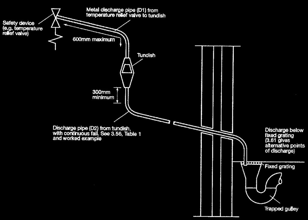
8 3.2 Electrical connections (Cont) able to reach the electrical connections. When the cylinder is moved into position the cables should be fed up another channel behind the casing at the front of the cylinder into the electrical box. When cables are in place they can be secured using the cable clamp supplied in the fittings bag 4. Pipe Connections Before connecting the cold supply, flush the cold supply pipework of all flux and debri. Lift off the cylinder lid allowing access to the combination valve and other connections. 4.1 Super S Check the expansion vessels and hose connections are tight. S 300: Fit the expansion vessel and bracket on a suitable wall close to the cylinder. Connect the flexible hose to the expansion vessel 4.2 Remove the template Position the cylinder to meet the heating and domestic water pipes. 4.3 Combination valve. The Combination valve at the top of the cylinder is factory fitted and is water-tight. If necessary it can be rotated in either direction to suit the connecting pipework, up to half a turn without losing its seal. 4.4 Cold mains supply. Connect the cold mains supply to the combination valve cold feed (Fig. 3). The OSO unvented unit is designed for use with supply pressure up to 8 bar. For water pressures above 8 bar an additional pressure reducing valve must be fitted to the cold water supply pipe 4.5 Hot water outlet. Connect the hot water distribution pipe to the combination valve hot water outlet (Fig. 3). Fig. 3 Cold mains supply Hot water outlet Balanced cold water 4.6 Balanced cold water supply (optional). If no balanced cold supply is required, tighten the supplied blanking cap. If a balanced mains pressure cold water supply is required to a shower or bidet (over rim type only, ascending spray type requires type AA,AB or AD air gap, remove blanking cap and connect to the shower or bidet cold supply on the combination valve (Major shower manufacturers advise fitting a mini expansion vessel in the balanced cold supply pipework to accomodate thermal expansion and prevent tightening of shower controls Using the balanced cold connection to feed bath taps can reduce the flow available to the unvented cylinder. 4.7 Expansion vessel (300 litre only) Site the expansion vessel on the wall using the supplied bracket and connect to the point K on the multifunction valve with copper pipe. 4.8 Flexible Y-hose The flexible Y-hose is preformed to the correct shape. Connect the inlet ends to the expansion relief valve and the temperature and pressure relief valve. 4.9 Tundish Recommended position of the tundish is to the left of the cylinder as seen from the front. Connect the tundish inlet to the outlet end of the flexible Y-hose. Tundish should be visible and positioned away from electrical devices. Tundish can be secured with supplied screws.

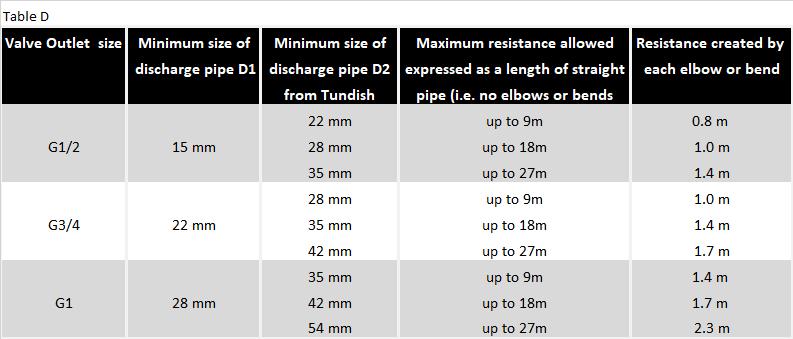
9 4.11 Primary flow & return Fit the elbows supplied to the primary flow & return connections. Make the boiler primary flow and return pipes to the unit. The motorised valve can be connected to either the primary flow or return pipe. Ensure that the direction of flow is correct. It is possible to fit the motorised valve on the flow pipe on its side to fit under the cylinder lid. For electrical connection of the motorised valve and immersion heater, please read Electrical Installation Instructions. (Pages 5) 4.12 Secondary return (optional) If a secondary return is connected, the cylinder thermostats should be set to a maximum of 60 C. Reduce thermostat settings to "smart -" on direct units. A secondary return can be connected via the expansion vessel connection to the combination valve. Remove the hose, connect a short length of 15 mm copper tube, fit a T piece, connect in the secondary return and reconnect the exp. vessel hose to the remaining T piece outlet. An additional expansion vessel will be required if the secondary return loop exceeds 10% of the cylinder capacity. 1 metre of 22 mm pipe holds approximately 1/3 litre of water. 15 mm pipes carry approximately half that volume. Secondary return must be pumped by a bronze pump and fitted with non return valves to ensure correct direction of flow. Fig. 4 T-piece conn. ( only) Flexible hose 4.10 Discharge pipe Connect the tundish outlet to the discharge pipe. Install the tundish in a vertical position within a maximum of 500 mm from the Temperature and Pressure Relief Valve drain connection. Ensure the expansion relief pipework discharges through the tundish. Tundish pipework must be 22 mm with a minimum vertical length of 300 mm below tundish. Maximum permitted length of 22 mm pipework is 9 m. Each bend or elbow is equivalent to 0.8 m of pipework. All pipework must have continous fall and discharge in a safe, visible position. If any doubt, refer to Building Regulation G3. Discharge pipe must be dedicated to the cylinder and must not be used for any other purpose. 5. Commissioning 5.1 Commissioning and filling 1. Check all connections for tightness. Open hot water tap furthest away from the OSO water heater. 2. Open the mains stop cock to fill the water heater. When water flows evenly from tap, allow to run for a few minutes to flush through any dirt, swarf or residue, then close the tap Open successive hot taps to purge any remaining air. 3. Check all water connections for leaks and rectify if necessary. 4. Manually operate Expansion relief valve B (see fig. 1 on page 3) to ensure free water flow through discharge pip by turning knob counterclockwise. To close continue to turn counter-clockwise until the valve shuts. Fit secondary return here according to section 4.12
10 5.1 Commissioning and filling (Cont) 5. Manually operate Temperature and Pressure Relief Valve C (see fig. 1 on page 3) to ensure free water flows through discharge pipe (Turn knob counter-clockwise). 6. Switch electrical power on. 7. Replace the cylinder lid this is important as the lid prevents heat loss from the cylinder and combination valve, conserving valuable energy. Do not place heavy objects on the lid. Alternative thermostats should not be used, regulations require immersion heaters on unvented cylinders to be connected with a thermal cut-out. Recommended torque is 0,2 kp (20Nm). End terminal must not exceed 10 mm MAX 10 mm 5.2 Draining Switch off the electrical power (Important to avoid damage to element. Isolate boiler from OSO unit. Turn off the cold water supply valve. Open hot water tap. Open drain at base of cylinder using a 6 mm hex key. The unit will drain. Draining process may be speeded up by opening the temperature and pressure relief valve. An internal ø18 mm hose can be applied to lead the water to a gully, sink or similar (see fig. 5) 5.3 System flushing System flushing will not be necessary under normal circumstances as the line strainer will prevent ingress of foreign materials, however if flushing is required, run at least 50 litres of water from the cylinder at the highest possible flowrate. Close the taps and follow draining procedure above. 6. ELECTRICAL INSTALLATION Wiring for immersions L RESET 2 4 IMMERSIO THERMOSTA N T N 6 9 Live feed 1 3 RESET Switched live CYLINDE THERMOSTA R Elemen toso 3kW 240V - 1 phase T Y- plan syste mtermina l Cable Clamp 6.1 Immersion heaters Power to immersion heaters should not be switched on until the unit is filled with water. All units are fitted with one 3 kw immersion heater which is located behind the electrical box. Immersion heaters must be wired through the factory fitted thermostat and thermal cut-out according to diagram on the reverse of the electrical box cover. 6.2 Wiring for immersions Follow the wiring instructions connecting the live, neutral and earth as indicated. The unit must be permanently connected to the electrical supply through a double-pole linked switch with a minimum break capacity of 13 amps. All internal wiring is factory mounted. Each immersion heater has a working thermostat adjustable between 40 C - 70 C.
11 6.2 Wiring for immersions (cont) A safety cut-out is also incorporated within the thermostat and will operate at 85 C ± 3 C. Should this happen, check reasons for thermal cut-out button being released and when satisified press the reset button Important: Before resetting the safety cutout or altering the thermostat setting, isolate electrical supply to the unit prior to removal of the lid. Ensure the lid to the electrical box is replaced correctly and the retaining screw is fitted 6.3 System wiring Motorised valve: To comply with regulations governing the installation of indirect unvented cylinders, a motorised valve must be fitted in the primary pipework. The wiring plan shown is based on the use of a 10-way Junction Box (Honeywell Part no ) terminal 10 is switched live and, if needed, terminal 9 is pump live. Your OSO unit has been supplied with a two port motorised valve, which will act as a positive energy cut-out should the safety cutout operate. The motorised valve will also control the temperature of the domestic stored water via the cylinder thermostat, which is located in the electrical box. The unit should be installed on an S or Y plan system. Please follow the wiring instructions carefully. The working thermostat which controls the temperature of the domestic hot water is adjustable between 40 C - 70 C. A safety cut out is also incorporated within the thermostat and will operate at 85 C ± 3 C. Should the safety cut out be brought into operation, the motorised valve will operate and close down the primary flow to the cylinder. To reset the safety cut-out and the motorised valve the reset button must be pressed in. If using a 6-wire 28mm or 1 BSP V4043H on either circuit the white wire is not needed and must be made electrically safe BOILER PUMP Basic Boiler L E N L N E
12 6.4 S plan wiring layout 2 Port Valve (supplied) Automatic bypass Pump flow
13 6.5 Y Plan wiring layout A Honeywell 10 way Junction Box must be used in a Y plan system. No other wiring centre is acceptable. 2 Port Valve (supplied) Mid Position Valve (not supplied) Automatic bypass Pump flow
14 7. SAFETY AND SERVICING Maintenance must be carried out by a competent person. 7.1 Safety Cut-out 1. The safety cut-out operates if: a. Wiring is incorrect. b. The immersion heater thermostat or cylinder thermostat fails. 2. Remember before resetting the safety cut-out or altering the thermostat setting, isolate electrical supply to the unit prior to removal of the electrical box lid. 3. Reduce thermostat setting and press the reset button. After adjustments are completed, ensure the lid to the electrical box is replaced correctly and the retaining screw is fitted 4. If still out of operation, contact installer. 7.2 Intermittent or slow discharge from tundish 1. Turn off the electrical supply to the immersion heaters. 2. Turn off cold water supply valve. 3. Open a hot tap. 4. Turn the knob on the Temperature and Pressure relief valve (5) to the left and hold in this position for thirty seconds 5. Check pre-charge on vessel and adjust pressure if necessary 6. Open cold water supply valve. 7. When water flows through open tap, close tap 9 Turn on electrical supply to the immersion heaters 7.3 Continous very hot water discharge from tundish This indicates a malfunction of a thermal cut-out, operating thermostat or the combined temperature and pressure relief valve. Turn off the electrical supply to the immersion heater and also isolate an indirect unit from the boiler. Contact the installer or competent engineer. 7.4 Expansion vessel maintenance The expansion vessels do not require annual maintenance and should not be tampered with 7.4 Expansion vessel maintenance (cont) unless an intermittent or slow discharge from the tundish occurs when water is being heated. In this situation, maintenance must be carried out by competent person and the precharge pressure must be restored to the original value. An annual visual inspection is recommended. Important: To check the precharge the expansion vessel must be completely empty of water. If the precharge pressure is different from the value shown on the label it must be restored to the original value. Do not remove expansion vessel without depressurizing the cylinder and draining 10 litres of water from the drain valve at the base of the cylinder. 7.5 Guarantee Cylinder should be serviced annually and benchmark logbook should be updated in order to validate guarantee. Logbook and service records act as guarantee document. For terms of guarantee please see Service logbook on page?? 7.6 Service Procedure The following maintenance work has to be carried out annually by a competent person. 6. Check the expansion vessel charge with a pressure gauge at the test point. 7. If the pressure is below 3.0 bar, top up with suitable air pressure pump.
15 7.6 Service Procedure 8. Complete the service section of Benchmark/ Cylinder Commissioning Checklist included in the inside back pages of these instructions. 9. Remove, clean and replace line strainer. 10. The immersion heater element must be removed for inspection on service after 5 years. The threads must be checked for corrosion. If signs of corrosion are evident, the element must be replaced. Subsequently the element must be removed and examined every 3 years. Failure to do so in areas of aggressive water may result in the element separating from the cylinder with consequential escape of water. 11. Visual inspection of all external valves and fittings. 7.6 Combination valve The combination valve can be separated into two sections by disconnecting the compression fitting in the middle. The entire valve can be removed by unscrewing from the top connection. When refitting, the valve does not tighten, the seal is created by a double Oring. To create the seal, the valve should be wound down until it will not go any further, then wound back up less than one full turn to point in the desired direction. Alternative Discharge Discharge pipes should be in metal and dedicated to the unvented cylinder. The pipe should have a continuous fall and should terminate in a safe and visible place.downward discharges at low level, i.e. up to 100 mm above external surfaces such as car parks, hard standings, grassed areas etc. are acceptable providing that where children may play or otherwise come into contact with discharges, a wire cage or similar guard is positioned to prevent contact, whilst maintaining visibility. Discharge at high level, i.e. into a metal hopper and metal down pipe with the end of the discharge pipe clearly visible (tundish visible or not) or onto a roof capable of withstanding high temperature discharges of water and 3 m from any plastics guttering system that would collect such discharges (tundish visible).where a single pipe serves a number of discharges, such as in blocks of flats, the number served should be limited to not more than 6 systems so that any installation discharging can be traced reasonably easily. The single common dis-charge pipe should be at least one pipe size larger than the largest individual discharge pipe to be connected. For further information contact your Building Control Office 7.7 Drain cock To remove drain cock, drain cylinder fully. When cylinder has drained, unscrew rear locking ring behind drain cock (turn clockwise). Pull drain cock off. Reverse procedure to refit drain cock. Locking ring only needs to be hand tight, seal comes from double o-ring.
16

17 8. OSO FAULT FINDING GUIDE

18 9. Technical and Performance specifications

19 IT IS THE RESPONSIBILITY OF THE INSTALLER TO COMPLETE THIS LOG BOOK AND PASS IT ON TO THE CUSTOMER. FAILURE TO DO SO MAY INVALIDATE THE CYLINDER GUARANTEE The code of practice for the installation, commissioning & servicing of mains pressure hot water storage Installation,Commissioning and Service Record Log Book CUSTOMER DETAILS NAME ADDRESS TEL No. IMPORTANT 1. Please, keep the Log Book in a safe place for future reference. 2. This Log Book is to be completed in full by the competent person(s) who commissioned the equipment and then handed to the customer. When this is done, the Log Book is a commissioning certificate that can be accepte as evidence of compliance with the appropriate Building Regulations. 3. Failure to install and commission this appliance to the manufacturer s instructions may invalidate the guarantee. The above does not affect your statutory rights. HEATING AND HOTWATER INFORMATION COUNCIL HWA charter members agree to: To supply fit for purpose products clearly and honestly describe To supply products that meet, or exceed appropriate standards and building and water regulations To provide pre and post sales technical support To provide clear and concise warranty details to customers For full details on the HWA charter please visit 19
20 1 Scope OSO Hotwater UK Ltd. (hereinafter called OSO) warrants for 2 years from the date of purchase, that the Product will: i) conform to OSO specification, ii) be free from defects in materials and workmanship, subject to conditions below. All components carry a 2- year warranty. The warranty is voluntarily extended by OSO to 25 years for the stainless steel inner tank under the conditions stated below. This extended warranty only applies to distributed by OSO or by a distributor where the Products have been originally sold by OSO. 2. Coverage If a defect arises and a valid claim is received within the statutory warranty period, at its option and to the extent permitted by law, OSO shall either; i) repair the defect, or; ii) replace the product with a product that is identical or similar in function, or; iii) refund the purchase price. If a defect arises and a valid claim is received after the statutory warranty period has expired, but within the extended warranty period, OSO will supply a product that is identical or similar in function. OSO will in such cases not cover any other associated costs. In addition, for every year after the statutory warranty period, the claimant must contribute 4 % of the list price of the cylinder in question to OSO. Any exchanged Product or component will become the legal property of OSO. Any valid claim or service does not extend the original warranty. The replacement Product or part does not carry a new warranty. 3. Conditions The Product is manufactured to suit most public water supplies. However, there are certain water chemistries (outlined below) that can have a detrimental effect on the Product and its life expectancy. If there are uncertainties regarding water quality, the local water supply authority can supply the necessary data. The warranty applies only if the conditions set out below are met in full: - The Product has been installed by a professional installer, in accordance with the instructions in the installation manual and all relevant Codes of Practice and Regulations in force at the time of installation. - The Product has not been modified in any way, tampered with or subjected to misuse and no factory fitted parts have been removed for unauthorized repair or replacement. 20
21 - The Product has not been modified in any way, tampered with or subjected to misuse and no factory fitted parts have been removed for unauthorized repair or replacement. - The Product has only been connected to a domestic mains water supply in compliance with the European Drinking Water Directive EN 98/83 EC, or latest version. The water should not be aggressive, i.e. the water chemistry shall comply with the following: o Chloride < 250 mg / L o TDS (Total Dissolved Solids) < 500 mg / L o Saturation Index C > - 1,0 / < 0,8 o ph level > 6,0 / < 9,5 - The immersion heater has not been exposed to hardness levels exceeding 10 dh (180 ppm CaCO3). A water softener is recommended in such cases. - Any disinfection has been carried out without affecting the Product in any way whatsoever. The Product shall be isolated from any system chlorination. - The Product has been in regular use from the date of installation. If the Product is not intended to be used for 60 days or more, it must be drained. - Service and/or repair shall be done according to the installation manual and all relevant codes of practice. Any replacement parts used shall be original OSO spare parts. - The Service record / Benchmark logbook has been completed and updated after each annual service. Invoices should be kept as proof of service. - The Commissioning Checklist / Benchmark certificate has been completed at the time of installation. - A copy of the purchase invoice and/or installation invoice as well as the defective product or component is made available to OSO upon request. - The immersion heater element must be removed for inspection on service after 5 years. The threads must be checked for corrosion. If signs of corrosion are evident, the element must be replaced. Subsequently the element must be removed and examined every 3 years. Failure to do so in areas of aggressive water may result in the element separating from the cylinder with consequential escape of water. Failure to follow these instructions and conditions may result in product failure, and water escaping from the Product. 4. Limitations The warranty does not cover: - Any fault or costs arising from incorrect installation, incorrect application, lack of regular maintenance in accordance with the installation manual, neglect, accidental or malicious damage, misuse, any alteration, tampering or repair carried out by a non-professional, any fault arising from the tampering with or removal of any factory fitted safety components or measures. - Cylinders connected to a private water supply. - Any consequential damage or any indirect loss caused by any failure or malfunction of the Product whatsoever. - Any pipework or any equipment connected to the Product. - The effects of frost, lightning, voltage variation, lack of water, dry boiling, excess pressure or chlorination procedures. - The effects of stagnant (de-aerated) water if the Product has been left unused for more than 60 days consecutively. - Damage caused during transportation. Buyer shall give the carrier notice of such damage. - Costs arising if the Product is not immediately accessible for servicing. These warranties do not affect the Buyer s statutory rights.
22 C C 21
23 SERVICE 1 DATE: SERVICE 2 DATE: ENGINEER NAME COMPANY NAME TEL No. COMMENTS ENGINEER NAME COMPANY NAME TEL No. COMMENTS SIGNATURE SIGNATURE SERVICE 3 DATE: SERVICE 4 DATE: ENGINEER NAME COMPANY NAME TEL No. COMMENTS ENGINEER NAME COMPANY NAME TEL No. COMMENTS SIGNATURE SIGNATURE SERVICE 5 DATE: SERVICE 6 DATE: ENGINEER NAME COMPANY NAME TEL No. COMMENTS ENGINEER NAME COMPANY NAME TEL No. COMMENTS SIGNATURE SIGNATURE SERVICE 7 DATE: SERVICE 8 DATE: ENGINEER NAME COMPANY NAME TEL No. COMMENTS ENGINEER NAME COMPANY NAME TEL No. COMMENTS SIGNATURE SIGNATURE SERVICE 9 DATE: SERVICE 10 DATE: ENGINEER NAME COMPANY NAME TEL No. COMMENTS SIGNATURE ENGINEER NAME COMPANY NAME TEL No. COMMENTS SIGNATURE HWSLB First Edition
24 OSO Hotwater AS Industriveien Hokksund - Norway Tel: oso@oso.no Alle deler av denne montasjeanvisningen er beskyttet av åndsverksloven og skal ikke reproduseres eller distribueres uten skriftlig avtale med produsenten. Forandringer forbeholdes. This installation manual and all its content is protected by copyright and may be reproduced or distributed only with written consent from the manufacturer. We reserve the right to make changes without notice.
PLEASE LEAVE THIS MANUAL WITH THE OSO UNIT AFTER INSTALLATION. For Super SXD, SX, SCI & SC
 PLEASE LEAVE THIS MANUAL WITH THE OSO UNIT AFTER INSTALLATION Super S Installation Manual For Super SXD, SX, SCI & SC This cylinder is manufactured and approved in accordance with EN 12897 : 2006 Contents
PLEASE LEAVE THIS MANUAL WITH THE OSO UNIT AFTER INSTALLATION INSTALLATION MANUAL
 PLEASE LEAVE THIS MANUAL WITH THE OSO UNIT AFTER INSTALLATION 0 RD 0 RI 0000-06 IM/ IM/a INSTALLATION MANUAL This manual gives detailed advice for installation and should be read carefully prior to fitting
PLEASE LEAVE THIS MANUAL WITH THE OSO UNIT AFTER INSTALLATION INSTALLATION MANUAL
 PLEASE LEAVE THIS MANUAL WITH THE OSO UNIT AFTER INSTALLATION SOLARCYL IM/SC INSTALLATION MANUAL This manual gives detailed advice for installation and should be read carefully prior to fitting any unvented
INSTALLATION MANUAL. Ecoline Geo RI HP PLEASE LEAVE THIS MANUAL WITH THE OSO UNIT AFTER INSTALLATION
 PLEASE LEAVE THIS MANUAL WITH THE OSO UNIT AFTER INSTALLATION Ecoline Geo RI HP INSTALLATION MANUAL The Ecoline GEO is an indirect unvented cylinder designed and approved for use with a heat pump. The
INSTALLATION MANUAL. Ecoline Geo RI HP PLEASE LEAVE THIS MANUAL WITH THE OSO UNIT AFTER INSTALLATION
 PLEASE LEAVE THIS MANUAL WITH THE OSO UNIT AFTER INSTALLATION 142039-02 GEO 9-2015 Ecoline Geo RI HP INSTALLATION MANUAL The Ecoline GEO is an indirect unvented cylinder designed and approved for use with
PLEASE LEAVE THIS MANUAL WITH THE OSO UNIT AFTER INSTALLATION INSTALLATION MANUAL
 PLEASE LEAVE THIS MANUAL WITH THE OSO UNIT AFTER INSTALLATION SLIMLINE INSTALLATION MANUAL This cylinder is manufactured and approved in accordance with EN 897:006. This manual gives detailed advice for
PLEASE LEAVE THIS MANUAL WITH THE AQUAFLOW UNIT AFTER INSTALLATION. For capacities litres
 PLEASE LEAVE THIS MANUAL WITH THE AQUAFLOW UNIT AFTER INSTALLATION Powermaster Installation Manual For capacities 120-300 litres This cylinder is manufactured and approved in accordance with EN 12897 :
PLEASE LEAVE THIS MANUAL WITH THE OSO UNIT AFTER INSTALLATION INSTALLATION MANUAL
 PLEASE LEAVE THIS MANUAL WITH THE OSO UNIT AFTER INSTALLATION 09-0 05-05 INSTALLATION MANUAL This cylinder is manufactured and approved in accordance with EN 897:006. This manual gives detailed advice
Unvented Calorifier Range. Operating and Maintenance Manual. For Models & 500
 Unvented Calorifier Range. Operating and Maintenance Manual. For Models 125 300 & 500 Telephone 08456 448802 Fax 08456 448803 Emial info@mhgheating.co.uk Web www.mhgheating.co.uk TABLE OF CONTENTS. Section
SEALED THERMAL STORE
 ISSUE 3 0717 INSTALLATION AND USER GUIDE ENERGYMANAGER SEALED THERMAL STORE ADVANCE APPLIANCES LTD PLEASE RETAIN AND ENSURE SERVICE RECORDS ARE KEPT UP TO DATE. SCHEMATIC DIAGRAM OF ENERYMANAGER THERMAL
ZIP Varipoint III. Installation, Maintenance and User Instructions. Models VP303, VP503 VP803, VP953 direct unvented water heaters. Issued August 2008
 Varipoint cover qxd:varipoint cover qxd 22/8/08 11:14 Page 1 Installation, Maintenance and User Instructions ZIP Varipoint III Models VP303, VP503 VP803, VP953 direct unvented water heaters Issued August
CROWN WATER HEATERS CPU10 - CPU15 CPOS10 - CPOS15
 CROWN WATER HEATERS CPU10 - CPU15 CPOS10 - CPOS15 COMPACT PLUS 10 and 15 Litre Unvented Under and Over Sink Water Heater INSTALLATION AND USER GUIDE 1 DIMENSIONS 10L - 250mm 15L - 310mm 100mm 80mm 410mm
POWERFLOW Series. Unvented Electric Storage Water Heaters. Installation & Operating Instructions Manual
 POWERFLOW Series Unvented Electric Storage Water Heaters Installation & Operating Instructions Manual These Instructions must be left with the user after installation. Version 3.0 June 2009 Hyco POWERFLOW
INSTALLATION MANUAL. RD SERIES Digital Electric Water Heater Wall-hung Unvented
 INSTALLATION MANUAL RD SERIES Digital Electric Water Heater Wall-hung Unvented WELCOME Dear Customer, Thank you for choosing the RD Series electric water heater, with an exclusive electronic temperature
1845 Tech Manual.qxd 23/11/05 1:20 pm Page 2 EXCELSIOR UNVENTED WATER HEATERS INSTALLATION MANUAL. Design for living
 1845 Tech Manual.qxd 23/11/05 1:20 pm Page 2 EXCELSIOR UNVENTED WATER HEATERS INSTALLATION MANUAL Design for living 1845 Tech Manual.qxd 23/11/05 1:21 pm Page 3 TECHNICAL DATA & INSTALLATION INSTRUCTIONS
Unvented Direct & Indirect Hot Water Cylinders (400L L)
") Unvented Direct & Indirect Hot Water Cylinders (400L - 2500L) Important Please read & understand all these instructions before commencing installation. Please leave this manual with the customer for future
Unvented Direct & Indirect Hot Water Cylinders (400L - 2500L) Important Please read & understand all these instructions before commencing installation. Please leave this manual with the customer for future
MEGAFLO HE Iss 1
 MEGAFLO HE 1 36 00 5843 Iss 1 Contents Contents SECTION PAGE 1 INTRODUCTION... 3 2 GENERAL REQUIREMENTS... 4 3 INSTALLATION - GENERAL... 5 4 INSTALLATION - DIRECT UNITS... 8 5 INSTALLATION - INDIRECT UNITS...
MW & EW 10 & 15 Litre Unvented Water Heaters HANDBOOK. IMPORTANT: This booklet should be given to the customer after installation and demonstration.
 MW & EW 10 & 15 Litre Unvented Water Heaters HANDBOOK IMPORTANT: This booklet should be given to the customer after installation and demonstration. Description of water heater 1) Hot water outlet 2) Temperature
Schuco SS-TC/SC Cylinders
 Cylinders Installation, User and Service Domestic Hot Water Cylinder Storage Capacities 90, 125, 150, 170, 200, 250 & 300, Litres Important -This should be left with the Cylinder after Installation Schueco
ADVANCE STAINLESS STEEL UNVENTED HOT WATER SYSTEMS
 ISSUE 2 DECEMBER 2013 INSTALLATION AND USER GUIDE ADVANCE STAINLESS STEEL UNVENTED HOT WATER SYSTEMS FOR GAS, OIL, ELECTRIC SOLAR AND HEAT PUMP SYSTEMS ADVANCE APPLIANCES LTD PLEASE RETAIN AND ENSURE SERVICE
Quantum. Installation, User and Service Manual. Hot Spring
 Hot Spring Domestic Hot Water Cylinder Storage Capacities 90, 125, 150, 170, 200, 250 and 300 Litres 1 Important - This Manual should be left with the householder after installation Index Section Page
Unvented Direct & Indirect Hot Water Cylinders (400L L)
") Unvented Direct & Indirect Hot Water Cylinders (400L - 2500L) Important Please read & understand all these instructions before commencing installation. Please leave this manual with the customer for future
Unvented Direct & Indirect Hot Water Cylinders (400L - 2500L) Important Please read & understand all these instructions before commencing installation. Please leave this manual with the customer for future
Installation & User Instructions
 Storage Cylinder Grant MonoWave System Indirect Heat Pump Cylinder Range Installation & User Instructions Part. DOC 74. Rev 04. January 2011 Contents 1 Introduction & General Requirements 3 1.1 Installation
AquaFlo II. Issue 3 December Please read these instructions carefully before commencing installation of the AquaFlo unvented water heater
 Installation, Maintenance and User Instructions AquaFlo II Issue 3 December 2011 Please read these instructions carefully before commencing installation of the AquaFlo unvented water heater Please leave
ADVANCE ELECTRIC THERMAL STORE
 ISSUE 13 1118 INSTALLATION AND USER GUIDE ADVANCE ELECTRIC THERMAL STORE ADVANCE APPLIANCES LTD HOUSEHOLDER PLEASE RETAIN AND ENSURE SERVICE RECORDS ARE KEPT UP TO DATE. 2 INTRODUCTION Advance thermal
Unvented Electric Water Heater 10/15 litre Undersink
 Unvented Electric Water Heater 10/15 litre Undersink Fitting Instructions and User Guide 1 CONTENTS SECTION PAGE 1.0 INTRODUCTION 2 2.0 TECHNICAL SPECIFICATION 3 3.0 INSTALLATION 4 4.0 COMMISSIONING 9
Powerflow Unvented water heater
 Product Instruction Manual Powerflow Unvented water heater 30, 50 and 90 litres v15.6/5 Thank you for purchasing a Powerflow series unvented electric water heater. The Powerflow is suitable for hand washing
Furrows Business Park, Haybridge Road Wellington, Telford, Shropshire TF1 2FE
 WATERHEATER MANUFACTURERS ASSOCIATION Tel 01952 257963 Fax 01952 253452 Furrows Business Park, Haybridge Road Wellington, Telford, Shropshire TF1 2FE www.telford-group.com STAINLESS PRODUCTS Tornado &
Instructions & Maintenance
 Instructions & Maintenance Issue 1 INTRODUCTION The corrosion resistant UVGold Unvented cylinder is made from Duplex Stainless Steel. It is highly insulated with environmentally friendly foam enclosed
KYROS INSTALLATION MANUAL KYROS. Digital Electric Water Heater Wall-hung Unvented
 KYROS INSTALLATION MANUAL KYROS Digital Electric Water Heater Wall-hung Unvented 02 KYROS WELCOME Dear Customer, Thank you for choosing the KYROS electric water heater, with an exclusive electronic temperature
ADVANCE ECB ELECTRIC COMBINATION BOILER
 ISSUE ISSUE 45 0115 0317 INSTALLATION AND USER GUIDE ADVANCE ECB ELECTRIC COMBINATION BOILER ADVANCE APPLIANCES LTD HOUSEHOLDER - PLEASE RETAIN AND ENSURE SERVICE RECORDS ARE KEPT UP TO DATE 1 SCHEMATIC
Bath Shower Mixer
 86004490 Bath Shower Mixer Installation and operating instructions The showerhead and hose supplied with this product are a safety critical part of your shower. Failure to use genuine Triton parts may
BOILING UNIT REDITAP. Installation and User Guide. IMPORTANT: This booklet should be left with the user after installation and demonstration
 in tap Boiling water to in tap sink Drain Valve (as high as possible) REDITAP CONNECTION SUMMARY Amp mains supply cold mains water into in tap optional filter cold water in hot water BOILING UNIT Installation
Alpha CombiMax 350 and 600
 Installation and Servicing Instructions Alpha CombiMax 350 and 600 Unvented Hot Water Store for use with the Alpha 240/280 Range of Gas Fired Combination Boilers For Technical help or for Service call...
Dene Bath Shower Mixer
 Dene Bath Shower Mixer Installation and operating instructions The showerhead and hose supplied with this product are an integral part of the safety of your shower. Failure to use genuine Triton parts
Instructions for Use Installation and Servicing
 0020004886A 18.01.05 Instructions for Use Installation and Servicing To be left with the user 12563 115-150-175-200-250-300 Unvented hot water storage cylinders Glow-worm, Nottingham Road, Belper, Derbyshire.
IMAGINATION SOLAR LTD. Installation Guide B1. Planning the Plumbing and Wiring
 Page 1 of 8 IMAGINATION SOLAR LTD Installation Guide B1 Planning the Plumbing and Wiring Unit 4 Montpelier Central, Station Road Bristol BS6 5EE t: 0117 942 6668 f: 0117 942 8998 e: enquiries@imaginationsolar.com
INTRODUCTION STORAGE PRIOR TO INSTALLATION. Expansion Vessel Hose. Part No High Flow Rate Inlet Control Set. Part No.
 INTRODUCTION The Worcester Greenskies cylinder is a Stainless Steel Unvented Twin Coil Storage vessel specifically designed to be installed in conjunction with the Worcester Greenskies solar package. Should
Installation and User Instructions Aquaheat Unvented Water Heaters Models: AH30H
 Installation and User Instructions Aquaheat Unvented Water Heaters Models: AH30H Please read and understand these instructions before starting work. Please leave this leaflet with the user following installation
Installation and User Instructions HS10U, HS15U.
 Installation and User Instructions HS10U, HS15U. MULTIPOINT Please read and understand these instructions before starting work. Please leave this leaflet with the user following installation PACK CONTENTS
TABLE OF CONTENTS TECHNICAL DOCUMENTATION 03. Technical Data Electrical Details Connection Details Dimensions Standing Losses
 INSPIRED H I G H H O T EF F ICIENCY E F F I C I E N C Y W A T E R S Y S T E M S E XT REME HIGH EFFICIENCY HO T W AT ER SY ST EMS w i th I N JECT I O N DYN A M I C S T ECHN I CAL DO CUME N TA T I O N I
PremierPlus Unvented Hot Water Cylinder Installation and User Manual
 PremierPlus Unvented Hot Water Cylinder Installation and User Manual 7032982_issue 07.indd 1 05/09/2017 12:17:57 Contents 1. Introduction... 3 1.1 General... 3 1.2 Symbols used... 3 1.3 Abbreviations...
Zircon Installation Manual
 Zircon Installation Manual Unvented Direct & Indirect Water Heaters Installation & Servicing Instructions Pack Contents Zircon Unvented water heater incorporating immersion heater(s) & thermal controls
ADVANCE UNIVERSAL MULTI-FUEL THERMAL STORE
 ISSUE 6 1016 INSTALLATION AND USER GUIDE ADVANCE UNIVERSAL MULTI-FUEL THERMAL STORE ADVANCE APPLIANCES LTD PLEASE RETAIN AND ENSURE SERVICE RECORDS ARE KEPT UP TO DATE. IMPORTANT: Gravity circultation
Contents. Commissioning 6 Operation 6 Routine Preventative Maintenance 6 Fault Finding 7 Spares Parts 8 Technical Support 9
 Contents Product Description 2 Approvals 2 Warranty 2 Warnings 2 Technical Specification 3 Installation 4 Location 4 Plumbing Connection 4 Electrical connection 5 Commissioning 6 Operation 6 Routine Preventative
Extreme Domestic Hot Water Loading System TECHNICAL DOCUMENTATION. Issue 11/09
 I N S P I R E D E F F I C I E N C Y Extreme Domestic Hot Water Loading System TECHNICAL DOCUMENTATION Issue 11/09 Technical data Description Extreme 200 Extreme 300 Extreme 500 Weight (empty) kg 63 77
aurostor Installation and maintenance instructions Installation and maintenance instructions For the competent person GB, IE VIH S GB...
 Installation and maintenance instructions For the competent person Installation and maintenance instructions aurostor VIH S GB.../3 GB, IE Publisher/manufacturer Vaillant GmbH Berghauser Str. 40 D-4859
APP STAINLESS UNVENTED HORIZONTAL HOT WATER CYLINDERS
 APP STAINLESS UNVENTED HORIZONTAL HOT WATER CYLINDERS INSTALLATION AND MAINTENANCE INSTRUCTIONS ISSUE 1 MAY 2016 PART NO. 024617 REV 1 01 STAINLESS UV IMPORTANT NOTE TO THE INSTALLER Read these instructions
Installation & Technical Guide. Domestic & Commercial.
 Installation & Technical Guide Domestic & Commercial www.challisbooster.com www.challisboosterplus.com Installation and Technical Guide Domestic and Commercial Challis Water Controls Europower House, Lower
INSTALLATION INSTRUCTIONS POINT OF USE WATER HEATERS EPU - US10 EPU - US15
 INSTALLATION INSTRUCTIONS POINT OF USE WATER HEATERS EPU - US10 EPU - US15 01 CONTENTS Special information 2 General information 3 Safety 5 Appliance description, cleaning, care & maintenance 7 Appliance
WC2 & WC3 Installation & Maintenance Instructions
 WC2 & WC3 Installation & Maintenance Instructions Please leave this instruction booklet with the home owner as it contains important guarantee, maintenance and safety information WC3 shown WC2 WC3 IMPORTANT
UNVENTED MAINS PRESSURE SOLAR WATER HEATERS 210, 250 AND 300 LITRE CAPACITY INDIRECT MODELS INSTALLATION AND SERVICING INSTRUCTIONS
 UNVENTED MAINS PRESSURE SOLAR WATER HEATERS 210, 250 AND 300 LITRE CAPACITY INDIRECT MODELS INSTALLATION AND SERVICING INSTRUCTIONS PACK CONTENTS The MAIN SOLAR unvented solar cylinder water heater incorporating
UNVENTED MAINS PRESSURE SOLAR WATER HEATERS 100 TO 300 LITRE CAPACITY DIRECT AND INDIRECT MODELS INSTALLATION AND SERVICING INSTRUCTIONS
 UNVENTED MAINS PRESSURE SOLAR WATER HEATERS 100 TO 300 LITRE CAPACITY DIRECT AND INDIRECT MODELS INSTALLATION AND SERVICING INSTRUCTIONS PACK CONTENTS Pullin Evolution unvented solar water heater incorporating
Please tape down. NewTeam Ltd. Customer Service Dept. Brunel Road Earlstrees Industrial Estate Corby Northants NN17 4JW
 3rd Fold 1st Fold NewTeam Ltd. Customer Service Dept. Brunel Road Earlstrees Industrial Estate Corby Northants NN17 4JW 2nd Fold Please tape down Please tape down Affix Stamp Installation Instructions
Megaflo HE issue 6
 Megaflo HE 1 36005823 issue 6 Contents Contents SECTION 1 INTRODUCTION... 3 2 GENERAL REQUIREMENTS... 4 3 INSTALLATION - GENERAL... 7 4 INSTALLATION - DIRECT UNITS... 16 5 INSTALLATION - INDIRECT UNITS...
Technical and Installation manual All Models
 WATER CONTROL setting the standards Technical and Installation manual All Models CONTENTS CONTENTS Section 1 Introduction 1-1 Introduction ---------------------------------------------- 2 1-2 System Layout
Cylinder Manual. Open Vented Cylinders Stainless Steel Water Heaters. Twin Coil TW180V TW210V TW250V TW300V Triple Coil TR250V TR300V
 Cylinder Manual Incorporating: User Instructions Installation Instructions Guarantee Registration Open Vented Cylinders Stainless Steel Water Heaters Products covered by this manual: Twin Coil TW180V TW10V
Advance Stainless Steel Unvented Hot Water Cylinders for Heat Pump Systems. Installation and Commissioning Manual
 Manual Advance Stainless Steel Unvented Hot Water Cylinders for Heat Pump Systems Installation and Commissioning Manual PLEASE RETAIN AND ENSURE SERVICE RECORDS ARE KEPT UP TO DATE. Copyright 2017 Kensa
INSTALLATION MANUAL. Domestic hot water tank with option kit for air to water heat pump system EKHWSU150B3V3 EKHWSU200B3V3 EKHWSU300B3V3 EKUHWB
 INSTALLATION MANUAL Domestic hot water tank with option kit for air to EKHWSU50BV EKHWSU00BV EKHWSU00BV EKUHWB EKUHWWB EKHWSU50BV EKHWSU00BV EKHWSU00BV EKUHWB EKUHWWB CONTENTS Page INTRODUCTION Introduction...
THE BOILING WATER DISPENSER INSTALLATION & OPERATING INSTRUCTIONS IMPORTANT: READ AND SAVE THESE INSTRUCTIONS FOR THE BENEFIT OF THE USER
 THE BOILING WATER DISPENSER INSTALLATION & OPERATING INSTRUCTIONS IMPORTANT: READ AND SAVE THESE INSTRUCTIONS FOR THE BENEFIT OF THE USER Thank you for choosing a quality Redring product manufactured by
Multipoint Technical Data
 Multipoint Technical Data Multipoint 10 / 15 Specification DIMENSIONS AND PERFORMANCE Model Multipoint 10 vertical Multipoint 15 vertical Multipoint 10 4.5kW vertical Multipoint 15 4.5kW vertical A - Height
MEGAFLO Eco Plus Solar Unvented Hot Water Cylinders 400L -570L
 MEGAFLO Eco Plus Solar Unvented Hot Water Cylinders 400L -570L Important Please read & understand all these instructions before commencing installation. Please leave this manual with the customer for future
IMPORTANT: PLEASE READ ALL THESE INSTRUCTIONS BEFORE COMMENCING INSTALLATION
 AIR TO WATER HEAT PUMP SYSTEM HOT WATER CYLINDER INDIRECT HEATING METHOD CLOSED OUTLET (UNVENTED) INSTALLATION AND SERVICE MANUAL HWS-1501CSHM3-UK HWS-2101CSHM3-UK HWS-3001CSHM3-UK 36006030_Issue_H 1 INSTALLATION
FRANKE MINERVA 3-IN-1 HOT WATER TAP HEATING TANK INSTALLATION GUIDE
 FRANKE MINERVA 3-IN-1 HOT WATER TAP HEATING TANK INSTALLATION GUIDE Introduction Thank you for purchasing this Franke product, which has been designed and manufactured to the highest quality standards.
AIRE. Thermostatic bath shower mixer. Installation and Operating Instructions INSTALLERS PLEASE NOTE THESE INSTRUCTIONS ARE TO BE LEFT WITH THE USER
 AIRE Thermostatic bath shower mixer Installation and Operating Instructions INSTALLERS PLEASE NOTE THESE INSTRUCTIONS ARE TO BE LEFT WITH THE USER 2180427C October 2005 CONTENTS Page Introduction 1 Safety
EPU - WM30 EPU - WM 50 EPU - WM100
 INSTALLATION INSTRUCTIONS WALL HUNG WATER HEATERS EPU - WM30 EPU - WM 50 EPU - WM100 MARCH 2018 PART NO. 025217 01 EVERFLO IMPORTANT NOTE TO THE INSTALLER Read these instructions before commencing installation.
ZIP VARIPOINT II Direct unvented water heaters.
 ZIP VARIPOINT II Direct unvented water heaters. MODEL NUMBER: VP103, VP153, VP103UB & VP153UB 1 TABLE OF CONTENTS General Product Description 3 Approvals 3 Technical Data 4 Dimensions 4 Safety Information
THERMflow Thermal Store Cylinders
 THERMflow Thermal Store Cylinders Technical Manual Tel: (01592) 611123 www.mcdonaldwaterstorage.com September 2018 THERMflow Thermal Store Tank Technical Manual Manual must be completed by Installer and
Megaflo Eco Plus Unvented Indirect Hot Water Cylinders 800L L
 Megaflo Eco Plus Unvented Indirect Hot Water Cylinders 800L - 1000L Important Please read & understand all these instructions before commencing installation. Please leave this manual with the customer
Hotflo. Unvented point of use hot water
 Unvented point of use hot water We developed the range for people who need a hot water supply for two to three basins or sinks. Flexible siting is a key design feature that we insisted upon because it
Mimosa dual control mixer shower Installation and operating instructions
 Mimosa dual control mixer shower Installation and operating instructions Installers please note these instructions are to be left with the user 2180443A September 2006 CONTENTS Page Introduction 1 Safety
Inta City Concealed Shower Mixing Valve CT80010CP
 Inta City Concealed Shower Mixing Valve CT80010CP Installation and Maintenance Instructions In this procedure document we have endeavoured to make the information as accurate as possible. We cannot accept
ENERSTORE. Vented Hot Water Storage System INSTRUCTIONS PLEASE LEAVE WITH HOUSEHOLDER
 ENERSTORE Vented Hot Water Storage System INSTRUCTIONS PLEASE LEAVE WITH HOUSEHOLDER Newark Copper Cylinder Co Ltd Brunel Drive Newark Notts. NG24 2EG Tel: 01636 678437 Fax: 01636 678964 Internet: www.newarkcoppercylinder.co.uk
Installation & User Instructions
 Storage Cylinder Grant DuoWave Plus System Triple Coil Solar Cylinder Range Installation & User Instructions Part. IRL 21. Rev 00. June 2011 Do not fit on a well or borehole supply Contents 1 Introduction
Please tape down. NewTeam Ltd. Customer Service Dept. Brunel Road Earlstrees Industrial Estate Corby Northants NN17 4JW
 3rd Fold 1st Fold NewTeam Ltd. Customer Service Dept. Brunel Road Earlstrees Industrial Estate Corby Northants NN17 4JW 2nd Fold Please tape down Please tape down Affix Stamp Installation Instructions
CROMO manual mixer shower
 CROMO manual mixer shower CAUTION! THIS PRODUCT IS NOT THERMOSTATICALLY CONTROLLED Installation and operating instructions Installers please note these instructions are to be left with the user 2180810C
TERMO ELECTRIC BOILER INSTALLATION MANUAL OSO TERMO RS -M
 TERMO ELECTRIC BOILER INSTALLATION MANUAL OSO TERMO RS -M Contents 1. Introduction... 1 1.1. Applicable documents... 1 1.2. Retention of documents... 1 1.3. Features & benefits... 1 1.4. Operation of domestic
Where the tap has a removable aerator on the spout exit it can be removed and cleaned periodically to maintain optimum flow performance.
 TAP6000 3 in Hot Tap Guarantee (UK only): 04-7 Your tap has the benefit of a comprehensive manufacturer s guarantee, details of which are shown on your Proof of Purchase Document. Any claim during the
Alpha FlowSmart 25 and 50
 Installation and Servicing Instructions Alpha FlowSmart 25 and 50 Hot Water System incorporating a Flue Gas Heat Recovery Device, Primary Store and an Alpha CD Condensing Combination Boiler For Technical
ZIP AquaFlo II. Models: Direct, Indirect and Solar Compatible. Unvented cylinder water heaters
 Installation & User Instructions ZIP AquaFlo II Unvented cylinder water heaters Models: Direct, Indirect and Solar Compatible. AquaFlo Installation, Maintenance and User Instructions Page 1 of 28 v 2.04
Installation, Operation & Maintenance Instructions
 Installation, Operation & Maintenance Instructions Please leave this instruction booklet with the owner as it contains important guarantee, maintenance and safety information Read this manual carefully
Dove Eco thermostatic bar mixer shower
 Dove Eco thermostatic bar mixer shower Eco Statement This product has been fitted with a flow regulator to deliver a maximum flow rate of 6 litres per minute. Installation and operating instructions Installers
Quartz. Digital. Bath with bath waste filler. Quartz Digital Bath with bath waste filler installation instuctions page 1
 Quartz Digital Bath with bath waste filler The Waste Electrical and Electronic Equipment (Producer Responsibility) Regulation 2004 This product is outside the scope of the European Waste Electrical and
Installation, Operating and Servicing Instructions
 Installation, Operating and Servicing Instructions Wall Mounted Water Boiler WMB3F/B,WMB3F/W Please make a note of your product details for future use: Date Purchased: Model Number: Serial Number: Dealer:
Oltis thermostatic bar mixer
 Oltis thermostatic bar mixer Installation and operating instructions Installers please note these instructions are to be left with the user 2180564E February 2009 CONTENTS Page Introduction... 1 Safety
NENE. Installation and Operating Instructions. Thermostatic bar mixer shower PLEASE NOTE THESE INSTRUCTIONS ARE TO BE LEFT WITH THE USER
 NENE Thermostatic bar mixer shower Installation and Operating Instructions INSTALLERS PLEASE NOTE THESE INSTRUCTIONS ARE TO BE LEFT WITH THE USER 2180430B October 2005 CONTENTS Page Introduction 1 Safety
Unvented water heater
 Unvented water heater Description of water heater 1)Hot water outlet 2)Temperature and pressure relief valve (30 litre only) 3)Cold water inlet 4)Control cover 5)Regulation knob 6)Heating neon Over-sink
Sanitary Water Tank INSTALLATION & SVC MANUAL
 http://biz.lgservice.com Sanitary Water Tank INSTALLATION & SVC MANUAL MODEL : PHS Series CAUTION Before Servicing the unit, read the safety precautions in this manual. Only for authorized service personnel.
TEMPRA. Wall Mounted Fan Flue System boiler. Wall mounted fanned flue boiler INSTALLATION AND USE INSTRUCTIONS. Appr. nr. B A - CE 0063 AQ 2150
 Wall Mounted Fan Flue System boiler Appr. nr. B 94.04 A - CE 0063 AQ 2150 Phone numbers: Installer Service Engineer Serial N Wall mounted fanned flue boiler INSTALLATION AND USE INSTRUCTIONS Please read
WATER HEATERS INSTALLATION MANUAL
 MHG Heating Ltd UNVENTED WATER HEATERS INSTALLATION MANUAL INCLUDING SOLAR VESSELS Techni cal data & installation instructions for MHG direct & indirect unvented water heaters including solar models. Your
T550i power shower pump Installation and operating instructions
 power shower pump Installation and operating instructions Installers please note these instructions are to be left with the user 2180149H March 2008 CONTENTS Page Plumbing and electrical notes...1 Introduction...2
H o t Wa te r Syste m s. Ultrasteel. Unvented Hot Water Cylinders. Exceeding the Standard
 H o t Wa te r Syste m s Unvented Hot Water Cylinders Ultrasteel Exceeding the Standard STEP UP TO... Ultrasteel... is the new Albion unvented hot water storage system. Based on the company s experience
Autofill counter top water boiler
 Autofill counter top water boiler Please read and keep these instructions For Burco counter top water boilers 76500 (SKU 444448531) and 76502 (SKU 444448533) Getting the best from your water boiler Remove
Autofill wall mounted water. boiler. Getting the best from your water. boiler. Please read and keep these instructions
 Autofill wall mounted water boiler Please read and keep these instructions For Burco wall mounted boilers 76700 (SKU 444448534), 76702 (SKU 444448546), & 76704 (SKU444448548) Getting the best from your
Sema thermostatic bar mixer Installation and operating instructions
 Sema thermostatic bar mixer Installation and operating instructions Installers please note these instructions are to be left with the user 2180579A September 2006 CONTENTS Page Introduction 1 Safety warnings
OWNER S MANUAL WARRANTY INFORMATION AND INSTALLATION INSTRUCTIONS PROFLO AND MARATHON ELECTRIC STORAGE WATER HEATERS
 OWNER S MANUAL WARRANTY INFORMATION AND INSTALLATION INSTRUCTIONS PROFLO AND MARATHON ELECTRIC STORAGE WATER HEATERS MODELS: 25V1, 25P1, 50V1, 50P1, 50H1, 80F1, 80H1, 125F1, 125F2, 125H1, 160F1, 160F2,
Unvented Direct & Indirect Hot Water Cylinders
 Unvented Direct & Indirect Hot Water Cylinders Megaflo Product Guide Contents Product Specification...Page 3 Installation and Commissioning Instructions...Page 11 Maintenance and Servicing...Page 27 User
Installation, Operation & Maintenance Instructions
 Installation, Operation & Maintenance Instructions Please leave this instruction booklet with the owner as it contains important guarantee, maintenance and safety information Read this manual carefully
Varsity Concealed Shower System
 VARSITY CONCEALED SHOWER SYSTEM Installation & aftercare instructions Please retain for future reference Varsity Dual Function Concealed Shower System Product code SVA1615 Varsity Single Function Concealed
TH100 Three in One Instant Hot Water Tap
 TH100 Three in One Instant Hot Water Tap Installation, Use and Maintenance Customer Care Department The Group Ltd. Harby Road Langar Nottinghamshire NG13 9HY T : 01949 862 012 F : 01949 862 003 E : customer.care@cda.eu