INSTALLATION INSTRUCTIONS
|
|
|
- Kathryn York
- 5 years ago
- Views:
Transcription

1 2006 Lennox Industries Inc. Dallas, Texas, USA RETAIN THESE INSTRUCTIONS FOR FUTURE REFERENCE INSTALLATION INSTRUCTIONS G61MPVT SERIES UNITS GAS UNITS 505,187M 06/2009 Litho U.S.A. Table of Contents Unit Dimensions G61MPVT Parts Arrangement Shipping and Packing List Safety Information Installation Setting Equipment Filters Duct System Pipe & Fittings Specifications Vent Piping Guidelines Joint Cementing Procedure Venting Practices Gas Piping Electrical Integrated Control Board Unit Start Up Gas Pressure Adjustment Manifold Pressure & High Altitude Information Other Unit Adjustments Heating Sequence of Operation Service Requirements General Combustion, Dilution & Ventilation Air Ignition Control Board Diagnostic Codes Troubleshooting Repair Parts List Vent Pipe Sizing Worksheet Start Up & Performance Check List WARNING FIRE OR EXPLOSION HAZARD. Failure to follow safety warnings exactly could result in serious injury, death, or property damage. Do not store or use gasoline or other flammable vapors and liquids in the vicinity of this or any other appliance. Installation and service must be performed by a qualified installer, service agency or the gas supplier. WHAT TO DO IF YOU SMELL GAS: Do not try to light any appliance. Do not touch any electrical switch; do not use any phone in your building. Leave the building immediately. Immediately call your gas supplier from a neighbor s phone. Follow the gas supplier s instructions. If you cannot reach your gas supplier, call the fire department. 06/09 Page 1 505,187M
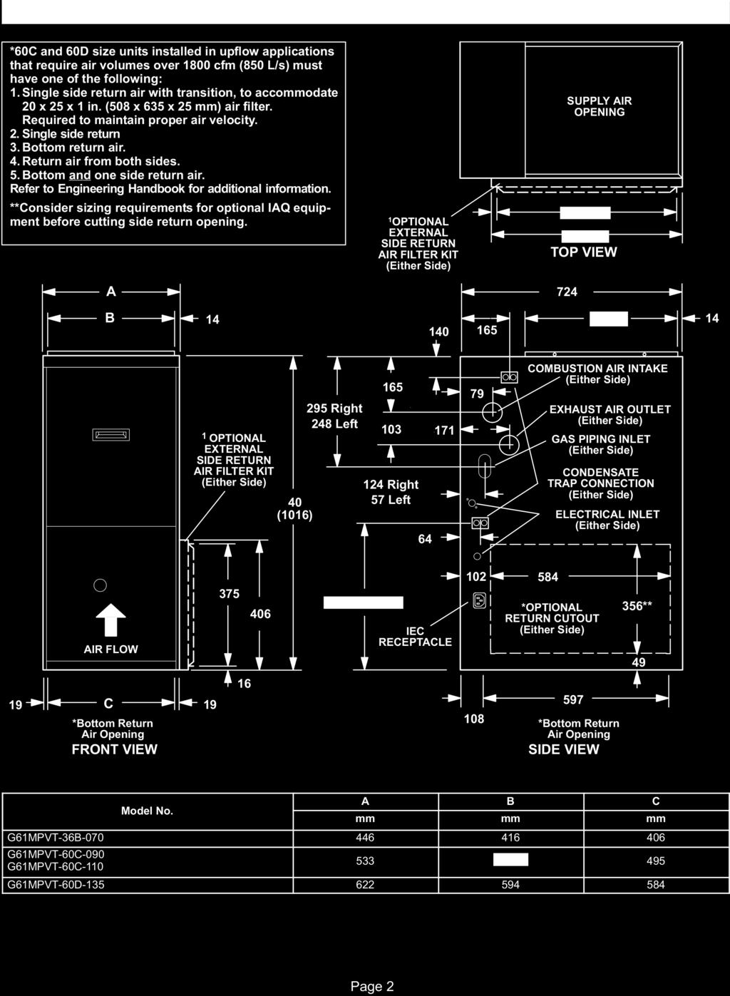
2 505
3 G61MPVT Parts Arrangement TOP CAP DuralokPlus TM HEAT EXCHANGER ASSEMBLY CABINET BURNER BOX ASSEMBLY GAS VALVE AND MANIFOLD FLUE COLLAR COMBUSTION AIR PRESSURE PROVE SWITCHES COMBUSTION AIR INDUCER WARM HEADER (COLLECTOR) BOX CONDENSER COIL BURNER ACCESS PANEL COLD HEADER (COLLECTOR) BOX PRIMARY LIMIT BLOWER ACCESS PANEL SECONDARY LIMITS (2) SIGHT GLASS DOOR INTERLOCK SWITCH Two Stage, Variable Speed Integrated Control Board CONTROL BOX TRANSFORMER BLOWER MOTOR FIGURE 1 Page 3
4 G61MPVT Gas Furnace The G61MPVT gas furnace is equipped with a two stage, variable speed integrated control. This control ensures compatibility with a thermostat which provides humidity control. Each G61MPVT is shipped ready for installation in the upflow, downflow, horizontal left air discharge or horizontal right air discharge position. The furnace is shipped with the bottom panel in place. The bottom panel must be removed if the unit is to be installed in upflow applications with bottom return air. The bottom panel must also be removed and discarded in all downflow or horizontal applications. The furnace is equipped for installation in natural gas applications. A conversion kit (ordered separately) is required for use in propane/lp gas applications. All G61MPVT models can be installed as a Direct Vent gas central furnace. G61MPVT 070, 090 and 110 models can be installed as a Non Direct Vent gas central furnace. TE In Direct Vent installations, combustion air is taken from outdoors and flue gases are discharged outdoors. In Non Direct Vent installations, combustion air is taken from indoors and flue gases are discharged outdoors. See figure 2 for applications involving roof termination. DIRECT VENT INSTALLATION COMBUSTION EXHAUST AIR INTAKE OUTLET OUTSIDE OF HOUSE N DIRECT VENT INSTALLATION EXHAUST OUTLET COMBUSTION AIR INTAKE INSIDE OF HOUSE Shipping and Packing List Package 1 of 1 contains 1 Assembled G61MPVT unit 1 Bag assembly containing the following: 3 Screws 3 Wire nuts 1 Snap bushing 1 Snap plug 1 Wire tie 1 Condensate trap 1 Condensate trap cap 2 2" diameter vent / intake plugs 1 3" diameter cabinet plug (intake) 2 2" diameter debris screen 1 Bag assembly containing the following: 1 50 hertz power wiring harness TE G61MPVT 60C 110 and 60D 135 units also include two 50mm to 80mm diameter ABS street elbows and two 80mm to 50mm ABS reducing elbows, which are shipped on the blower deck in the heating compartment. The following items may also be ordered separately: 1 Thermostat 1 Propane/LP changeover kit Check equipment for shipping damage. If you find any damage, immediately contact the last carrier. Safety Information WARNING Improper installation, adjustment, alteration, service or maintenance can cause property damage, personal injury or loss of life. Installation and service must be performed by a qualified installer, service agency or the gas supplier. CONDENSATE DRAIN G61MPVT FIGURE 2 G61MPVT CONDENSATE DRAIN CAUTION As with any mechanical equipment, personal injury can result from contact with sharp sheet metal edges. Be careful when you handle this equipment. Page 4
5 Installation Setting Equipment WARNING Do not install the furnace on its front or its back. Do not connect the return air ducts to the back of the furnace. Doing so will adversely affect the operation of the safety control devices, which could result in personal injury or death. Select a location that allows for the required clearances that are listed on the unit nameplate. Also consider gas supply connections, electrical supply, vent connection, condensate trap and drain connections, and installation and service clearances [610 mm (24 inches) at unit front]. The unit must be level from front to back and side to side. TE G61MPVT 36B units with 1/2 hp blower motors are equipped with three flexible legs and one rigid leg. The rigid leg is equipped with a shipping bolt and a flat white plastic washer (rather than the rubber mounting grommet used with a flexible mounting leg). The bolt and washer must be removed before the furnace is placed into operation. After the bolt and washer have been removed, the rigid leg will not touch the blower housing. TE G61MPVT 60D 135 units are equipped with a shipping pad under the blower housing. Remove the shipping pad prior to operation. Allow for clearances to combustible materials as indicated on the unit nameplate. Minimum clearances for closet or alcove installations are shown in figures 3, 9 and 6. WARNING Blower access panel must be securely in place when blower and burners are operating. Gas fumes, which could contain carbon monoxide, can be drawn into living space resulting in personal injury or death. WARNING Improper installation of the furnace can result in personal injury or death. Combustion and flue products must never be allowed to enter the return air system or air in the living space. Use sheet metal screws and joint tape to seal return air system to furnace. In platform installations with furnace return, the furnace should be sealed airtight to the return air plenum. A door must never be used as a portion of the return air duct system. The base must provide a stable support and an airtight seal to the furnace. Allow absolutely no sagging, cracks, gaps, etc. For no reason should return and supply air duct systems ever be connected to or from other heating devices such as a fireplace or stove, etc. Fire, explosion, carbon monoxide poisoning, personal injury and/or property damage could result. Upflow Applications The G61MPVT gas furnace can be installed as shipped in the upflow position. Refer to figure 3 for clearances. Left Side Top/Plenum Installation Clearances Top Bottom (Floor) Right Side 25 mm (1 in.) *Front 0 Back 0 Sides 0 Vent 0 Floor 0 *Front clearance in alcove installation must be 610 mm (24 inches). Maintain a minimum of 610 mm (24 inches) for front service access. Allow proper clearances to accommodate condensate trap and vent pipe installation. For installations on a combustible floor, do not install the furnace directly on carpeting, tile or other combustible materials other than wood flooring. FIGURE 3 Return Air Upflow Units TE G61MPVT 135 models are not approved for installation in upflow air discharge applications. Return air can be brought in through the bottom or either side of the furnace installed in an upflow application. If the furnace is installed on a platform with bottom return, make an airtight seal between the bottom of the furnace and the platform to ensure that the furnace operates properly and safely. The furnace is equipped with a removable bottom panel to facilitate installation. Markings are provided on both sides of the furnace cabinet for installations that require side return air. Cut the furnace cabinet at the maximum dimensions shown on page 2. TE When air volumes over 850 L/s (1800 cfm) are required with 60C or 60D models in an upflow application, the following return air options are available: 1 Return air from single side with transition which will accommodate508 x 635 x 25 mm (20 x 25 x 1 in.) air filter. (Required to maintain proper air velocity.) See figure 4. 2 Return air from single side. 3 Return air from bottom. 4 Return air from both sides. Page 5
6 5 Return air from bottom and one side. Refer to Engineering Handbook for additional information. G61MPVT applications which include side return air and a condensate trap installed on the same side of the cabinet require either a return air base or field fabricated transition to accommodate an optional IAQ accessory taller than 368mm (14.5 inches). Side Return Air (with transition and filter) Horizontal Applications G61MPVT furnaces, with the exception of the G61MPVT 60D 135, can be installed in horizontal applications with either right or left hand air discharge. The G61MPVT 60D 135 can only be installed in horizontal applications with right hand air discharge. Refer to figure 6 for clearances in horizontal applications. Horizontal Application Installation Clearances Right Hand Discharge Top 508mm X635mm X 25mm (20" X 25" X 1") Air Filter Left End Right End Bottom (Floor)** Return Air Plenum Left End Left Hand Discharge Top Right End Transition FIGURE 4 Removing the Bottom Panel Remove the two screws that secure the bottom cap to the furnace. Pivot the bottom cap down to release the bottom panel. Once the bottom panel has been removed, reinstall the bottom cap. See figure 5. Screw Removing the Bottom Panel Bottom Panel Bottom Cap Bottom (Floor)** Top 0 Front* 0 Back 0 Ends 0 Vent 0 Floor 0 *Front clearance in alcove installation must be 610 mm (24 inches). Maintain a minimum of 610mm (24 inches) for front service access. **A 140mm (5 1/2 ) service clearance must be maintained below the unit to provide for servicing of the condensate trap. For installations on a combustible floor, do not install the furnace directly on carpeting, tile or other combustible materials other than wood flooring. FIGURE 6 This furnace may be installed in either a roof space or under floor. Install the furnace on a field fabricated raised platform, as shown in figure 7. The unit must be supported at both ends and beneath the blower deck to prevent sagging. TE In horizontal applications, the unit must be level side to side. The unit may be tilted back to front a maximum of 25mm (1 inch) to ensure proper draining of the heat exchanger. The heat exchanger coil will not drain properly if the unit is tilted backward. FIGURE 5 Page 6
7 TYPICAL HORIZONTAL ROOF SPACE INSTALLATION (FORCED AIR FURNACE) INTAKE PIPE EXHAUST PIPE GAS CONNECTOR TE Condensate trap and condensate line must be protected by self regulating heating cable and insulation when run through unconditioned spaces. RAISED PLATFORM SERVICE PLATFORM CONDENSATE LINE FIGURE 7 Platform Installation of Horizontal Unit in Roof Space 1 Select location for unit keeping in mind service and other necessary clearances. See figure 6. 2 Construct a raised wooden frame and cover frame with a plywood sheet. Provide a service platform for unit. A drain pan is also recommended. 3 Route auxiliary drain line so that water draining from this outlet will be easily noticed by the homeowner. INTAKE PIPE EXHAUST PIPE 4 Set unit in drain pan (if used) as shown in figure 7. Unit must be level to ensure proper coil drainage. Leave 140mm (5 1/2 inches) for service clearance below unit for condensate trap. 5 Continue with exhaust, condensate and intake piping installation according to instructions. Platform Installation of Horizontal Unit Installed Under Floor 1 Select location for unit, keeping in mind service and other clearances. EVAPORATOR COIL FIGURE 8 2 After positioning cement blocks, mount support frame on top of blocks and install unit. Unit must be level to ensure proper heat exchanger coil drainage. Leave 140mm (5 1/2 inches) for service clearance) for condensate trap. 3 Install exhaust and intake piping according to information given in following section. Page 7
8 Return Air Horizontal Applications Return air may be brought in only through the end of a furnace installed in the horizontal position. The furnace is equipped with a removable bottom panel to facilitate installation. See figure 5. Downflow Applications The unit may be installed three ways in downflow applications: on non combustible flooring, on combustible flooring using an additive base, or on a reverse flow cooling cabinet. Do not drag the unit across the floor in the downflow position. Flange damage will result. Refer to figure 9 for clearances in downflow applications. Downflow Application Installation Clearances Top Left Side Bottom Right Side Top 0 *Front 0 Back 0 Sides 0 Vent 0 Floor NC *Front clearance in alcove installation must be 610mm (24 inches). Maintain a minimum of 610mm (24 inches) for front service access. Allow proper clearances to accommodate condensate trap and vent pipe installation. The furnace may be installed on a combustible wood floor if an optional additive base is installed between the furnace and the combustible floor. FIGURE 9 Installation on Non Combustible Flooring 1 Cut floor opening keeping in mind clearances listed on unit rating plate. Also keep in mind gas supply connections, electrical supply, flue and air intake connections and sufficient installation and servicing clearances. See table 1 for correct floor opening size. 2 Flange warm air plenum and lower the plenum into the opening. 3 Set the unit over the plenum and seal the plenum to the unit. 4 Ensure that the seal is adequate. TABLE 1 N COMBUSTIBLE FLOOR OPENING SIZE Front to Rear Side to Side Model No. in. mm in. mm B Cabinet (445mm) 19 3/ /8 422 C Cabinet (533mm) 19 3/ /8 511 D Cabinet (622mm) 19 3/ /8 600 TE Floor opening dimensions listed are 1/4 inch (6 mm) larger than the unit opening. See dimension drawing on page 2. Installation on Combustible Flooring 1 When unit is installed on a combustible floor, an additive base must be installed between the furnace and the floor. The base must be ordered separately for the following cabinet sizes: B cabinet 445mm # 11M60 C cabinet 533mm # 11M61 D cabinet 622mm # 11M62 See table 2 for opening size to cut in floor. CAUTION The furnace and additive base shall not be installed directly on carpeting, tile, or other combustible material other than wood flooring. TABLE 2 ADDITIVE BASE FLOOR OPENING SIZE Front to Rear Side to Side Model in. mm in. mm B Cabinet (445mm) /4 476 C Cabinet (533mm) /4 578 D Cabinet (622mm) / After opening is cut, set additive base into opening. 3 Check fiberglass strips on additive base to make sure they are properly glued and positioned. 4 Lower supply air plenum into additive base until plenum flanges seal against fiberglass strips. TE Be careful not to damage fiberglass strips. Check for a tight seal. 5 Set the furnace over the plenum. 6 Ensure that the seal between the furnace and plenum is adequate. Page 8
9 G61MPVT UNIT PLENUM (Field Provided) SEALING STRIP (Field Provided) PROPERLY SIZED FLOOR OPENING FIGURE 10 SUPPLY AIR PLENUM ADDITIVE BASE Installation on Cooling Cabinet 1 Refer to reverse flow coil installation instructions for correctly sized opening in floor and installation of cabinet. 2 When cooling cabinet is in place, set and secure the furnace according to the instructions that are provided with the cooling coil. Secure the furnace to the cabinet. 3 Seal the cabinet and check for air leaks. Return Air Opening Downflow Units Return air may be brought in only through the top opening of a furnace installed in the downflow position.the following steps should be taken when installing plenum: 1 Bottom edge of plenum should be flanged with a hemmed edge (See figure 11 or 12). 2 Sealing strips should be used to ensure an airtight seal between the cabinet and the plenum. 3 In all cases, plenum should be secured to top of furnace using sheet metal screws. 4 Make certain that an adequate seal is made. PLENUM (Field Provided) SEALING STRIP (Field Provided) Side View FIGURE 11 SECURE FROM OUTSIDE CABINET CABINET SIDE PANEL SECURE FROM INSIDE CABINET Side View FIGURE 12 CABINET SIDE PANEL Filters This unit is not equipped with a filter or rack. A field provided filter is required for the unit to operate properly. Table 3 lists recommended minimum filter sizes. A filter must be in place when the unit is operating. TE In upflow applications where side return air filter is installed on same side as the condensate trap, filter rack must be installed beyond condensate trap to avoid interference. TABLE 3 Furnace Filter Size mm Cabinet Size Side Return Bottom Return 445mm 406 X 635 X 25 (1) 406 X 635 X 25 (1) 533mm 406 X 635 X 25 (1) 508 X 635 X 25 (1) 622mm 406 X 635 X 25 (2) 610 X 635 X 25 (1) Duct System Use industry-approved standards to size and install the supply and return air duct system. This will result in a quiet and low-static system that has uniform air distribution. TE Operation of this furnace in heating mode (indoor blower operating at selected heating speed) with an external static pressure which exceeds 200 Pa (0.8 inches w.c.) may result in erratic limit operation. Supply Air Plenum If the furnace is installed without a cooling coil, a removable access panel should be installed in the supply air duct. The access panel should be large enough to permit inspection (either by smoke or reflected light) of the heat exchanger for leaks after the furnace is installed. If present, this access panel must always be in place when the furnace is operating and it must not allow leaks into the supply air duct system. Return Air Plenum Return air must not be drawn from a room where this furnace, or any other gas appliance (ie., a water heater), is installed. When return air is drawn from a room, a negative pressure is created in the room. If a gas appliance is operating in a room with negative pressure, the flue products can be pulled back down the vent pipe and Page 9
10 into the room. This reverse flow of the flue gas may result in incomplete combustion and the formation of carbon monoxide gas. This toxic gas might then be distributed throughout the house by the furnace duct system. Return air can be brought in through the bottom or either side of the furnace. If a furnace with bottom return air is installed on a platform, make an airtight seal between the bottom of the furnace and the platform to ensure that the unit operates properly and safely. Use fiberglass sealing strips, caulking, or equivalent sealing method between the plenum and the furnace cabinet to ensure a tight seal. If a filter is installed, size the return air duct to fit the filter frame. Pipe & Fittings Specifications All pipe and fittings to be Pressure Pipe, Class E / Class 12 / Schedule 40 or equivalent All pipe, fittings, primer and solvent cement must conform with Australian standards. The solvent shall be free flowing and contain no lumps, undissolved particles or any foreign matter that adversely affects the joint strength or chemical resistance of the cement. The cement shall show no gelation, stratification, or separation that cannot be removed by stirring. CAUTION Solvent cements for plastic pipe are flammable liquids and should be kept away from all sources of ignition. Do not use excessive amounts of solvent cement when making joints. Good ventilation should be maintained to reduce fire hazard and to minimize breathing of solvent vapors. Avoid contact of cement with skin and eyes. Table 4 lists the available exhaust termination kits, as well as vent pipe equivalencies which must be used when sizing vent pipe. All Lennox vent terminations are PVC or ABS. TABLE 4 OUTDOOR TERMINATION KITS AND CORRESPONDING EQUIVALENCIES Vent Pipe Length Equivalency (meters) UNIT MODEL VENT PIPE DIA. (in.) Outdoor Exhaust Accelerator (Dia. X Length) Outdoor Exhaust Accelerator (Dia. X Length) 40mm (1 1/2") Concentric Kit 50mm (2") Concentric Kit 80mm (3") Concentric Kit 50mm (2") Wall Plate Kit 80mm (3") Wall Plate Kit 50mm (2") Wall Ring Kit 40mm X 305mm 50mm X 305mm 71M80 60M29 60L46 22G44 44J40 15F mm 1.2 Not 80mm 2.4 Not 100mm 4.3 Not 50mm 80mm 100mm 80mm 100mm 80mm 100mm Not Not Not Not Not Not Not 0.3 Not 0.6 Not 1.2 Not 0.6 Not 1.2 Not 1.8 Not 3.0 Not *Requires field provided and installed 40mm exhaust accelerator. 3.6 Not 7.3 Not 12.8 Not Not Not Not.9.9 Not Not Not Not Not Not Not 4.6 Not 7.6 Not * * * ** ** ** **Requires field provided and installed 50mm exhaust accelerator. Not Not Page 10
11 Vent Piping Guidelines G61MPVT furnaces, with the exception of the G61MPVT 60D 135, can be installed as either a Non Direct Vent or a Direct Vent gas central furnace. The G61MPVT 60D 135 can only be installed as a Direct Vent (two pipe) gas central furnace. TE In Non-Direct Vent installations, combustion air is taken from indoors and flue gases are discharged outdoors. In Direct Vent installations, combustion air is taken from outdoors and flue gases are discharged outdoors. Intake and exhaust pipe sizing in Direct Vent applications and exhaust pipe sizing in Non-Direct Vent applications Size pipe according to tables 5 and 6. Table 5 lists the minimum equivalent vent pipe lengths permitted. Table 6 lists the maximum equivalent pipe lengths permitted. Maximum vent length is defined as: Total length (linear meters) of pipe, Plus Equivalent length (meters) of fittings, Plus Equivalent length (meters) of termination. TE Include ALL pipe and ALL fittings, both in doors and outdoors. Regardless of the diameter of pipe used, the standard roof and wall terminations described in section Exhaust Piping Terminations should be used. Exhaust vent termination pipe is sized to optimize the velocity of the exhaust gas as it exits the termination. Refer to table 7. TE The exhaust pipe should be offset a minimum of 305mm (12 inches) to avoid the possibility of water droplets being released from the exhaust termination. The minimum exhaust vent length is 4.5m (15 feet). Shorter exhaust vent lengths may result in the discharge of water droplets from the exhaust termination, in spite of the 305mm (12 inch) vertical offset. Each 90 elbow (including those provided with the furnace) of any diameter is equivalent to 1.5m (5 feet ) of vent pipe of the same diameter. Two 45 elbows are equivalent to one 90 elbow of the same diameter. One 45 elbow is equal to.76m (2.5 feet) of vent pipe of the same diameter. In some applications which permit the use of several different sizes of vent pipe, a combination vent pipe may be used. Contact Lennox for assistance in sizing vent pipe in these applications. TE The flue collar on all models is sized to accommodate 50mm Schedule 40 / Class 12 / Class E pressure pipe. When vent pipe which is larger than 50mm must be used in an upflow application, a 50mm elbow must be applied at the flue collar in order to properly transition to the larger diameter flue pipe. This elbow must be added to the elbow count used to determine acceptable vent lengths. Assign an equivalent meter value to this elbow according to the larger size pipe being used. Contact Lennox for more information concerning sizing of vent systems which include multiple pipe sizes. Exhaust Pipe Offset 305mm Min. 305mm Min. 305mm Min. Upflow and Downflow Application Rooftop Termination Upflow and Downflow Application Side Wall Termination 305mm Min. Horizontal Application Rooftop Termination Horizontal Application Side Wall Termination FIGURE 13 Page 11
12 Use the following steps to correctly size vent pipe diameter. Refer to Vent Pipe Size Determination Worksheet on page Determine the vent termination and its corresponding equivalent meter value per table 6. 2 Determine the number of 90 elbows required for both indoor and outdoor use. Calculate the corresponding equivalent meters of vent pipe. 3 Determine the number of 45 elbows required for both indoor and outdoor use. Calculate the corresponding equivalent meters of vent pipe. 4 Determine the length of straight pipe required. 5 Add the total equivalent meters calculated in steps 1 through 4 and compare that length to the maximum values given in table 6 for the proposed vent pipe diameter. If the total equivalent length required exceeds the maximum equivalent length listed in the appropriate table, evaluate the next larger size pipe. TABLE 5 MINIMUM VENT PIPE LENGTHS G61MPVT MODEL 070, *** 135*** MIN. EQUIV. VENT LENGTH 4.5m* EXAMPLE 1.5m plus 2 elbows of 50mm or 80mm diameter pipe 1.5m plus 2 elbows of 80mm diameter pipe 1.5m plus 2 elbows of 80mm diameter pipe *Any approved termination may be added to the minimum equivalent length listed. **G61MPVT 60C 110 and G61MPVT 60D 135 must have 90 street ell (supplied) installed directly into unit flue colla and 50mm to 80mm reducer (supplied) must be installed on the 50mm ell. TE All 90 elbows used in configuration of vent, must be sweep elbows. TABLE 6 MAXIMUM VENT PIPE LENGTHS ALTITUDE G61MPVT MODEL MAXIMUM EQUIVALENT VENT LENGTH METERS 50mm dia. 80mm dia. 100mm dia m * n/a * n/a m 090 n/a * n/a * n/a n/a n/a n/a Not allowed. *G61MPVT 60C 110 and G61MPVT 60D 135 must have 90 street ell (supplied) installed directly into unit flue colla and 50mm to 80mm reducer (supplied) must be installed on the 50mm ell. TE All 90 elbows used in configuration of vent, must be sweep elbows. IMPORTANT The G61MPVT unit is not suitable for use at elevations over 610m. Joint Cementing Procedure All cementing of joints should be done according to the relevant local authority. WARNING DANGER OF EXPLOSION! Fumes from PVC glue may ignite during system check. Allow fumes to dissipate for at least 5 minutes before placing unit into operation. 1 Measure and cut vent pipe to desired length. 2 Debur and chamfer end of pipe, removing any ridges or rough edges. If end is not chamfered, edge of pipe may remove cement from fitting socket and result in a leaking joint. 3 Clean and dry surfaces to be joined. 4 Test fit joint and mark depth of fitting on outside of pipe. 5 Uniformly apply liberal coat of PVC primer for PVC or ABS cleaner for ABS to inside socket surface of fitting and male end of pipe to depth of fitting socket. 6 Promptly apply solvent cement to end of pipe and inside socket surface of fitting. Cement should be applied lightly but uniformly to inside of socket. Take care to keep excess cement out of socket. Apply second coat to end of pipe. TE Time is critical at this stage. Do not allow primer to dry before applying cement. 7 Immediately after applying last coat of cement to pipe, and while both inside socket surface and end of pipe are wet with cement, forcefully insert end of pipe into socket until it bottoms out. Turn pipe 1/4 turn during assembly (but not after pipe is fully inserted) to distribute cement evenly. TE Assembly should be completed within 20 seconds after last application of cement. Hammer blows should not be used when inserting pipe. 8 After assembly, wipe excess cement from pipe at end of fitting socket. A properly made joint will show a bead around its entire perimeter. Any gaps may indicate a defective assembly due to insufficient solvent. 9 Handle joints carefully until completely set. Page 12
13 Venting Practices 1 Use recommended piping materials for exhaust piping (Class E / Class 12 / Schedule 40). 2 Secure all joints so that they are gas-tight using approved cement. Suspend piping using hangers at a minimum of every 1.52m (5 feet) for Schedule STRAPPING 40 vent pipe. A suitable (metal, plastic hanger can be fabricated or large wire by using metal or plastic ties) strapping or a large wire tie. 3 In areas where piping penetrates joists or interior walls, hole must be large enough to allow clearance FIGURE 14 on all sides of pipe through center of hole using a hanger. 4 Isolate piping at the point where it exits the outside wall or roof in order to prevent transmission of vibration to the structure. 5 When furnace is installed in a residence where unit is shut down for an extended period of time, such as a vacation home, make provisions for draining condensate collection trap and lines. Exhaust Piping (Figures 15 and 16) TE Two 50mm diameter street ells and two 80mm to 50mm reducers are contained in a bag assembly strapped to the blower deck of 60C 110 and 60D 135 units. The street ells must be glued directly into the unit flue collar. See figure 15. The 80mm to 50mm reducers must be glued to the street ells in upflow or downflow applications. 1 Choose the appropriate side for venting in upflow or downflow positions. Exhaust piping exits from the top of the unit in horizontal air discharge applications. Glue the field provided exhaust vent pipe (or provided street ell or reducing ell in upflow or downflow applications) to the flue collar. Refer to pipe and fittings specifications and gluing procedures. IMPORTANT Exhaust piping and condensate trap must be installed on the same side of the unit in upflow and dowflow applications. 2 All horizontal runs of exhaust pipe must slope back toward unit. A minimum of 6mm (1/4") drop for each 305mm (12 inches) of horizontal run is mandatory for drainage. Horizontal runs of exhaust piping must be supported every 1.5m (5 feet) using hangers. TE Exhaust piping should be checked carefully to make sure there are no sags or low spots. 3 On the opposite side of the cabinet, glue the provided 50mm vent plug into the unused flue collar. 4 Route piping to outside of structure. Continue with installation following instructions given in piping termination section. CAUTION Do not discharge exhaust into an existing stack or stack that also serves another gas appliance. If vertical discharge through an existing unused stack is required, insert PVC pipe inside the stack until the end is even with the top or outlet end of the metal stack. CAUTION The exhaust vent pipe operates under positive pressure and must be completely sealed to prevent leakage of combustion products into the living space. Page 13
14 TYPICAL EXHAUST PIPE CONNECTIONS AND CONDENSATE TRAP INSTALLATION IN UPFLOW OR DOWNFLOW DIRECT OR N DIRECT VENT APPLICATIONS (Right Hand Exit in Upflow Application Shown) 80mm PLUG PLUG 50mm TRANSITION 50mm G61MPVT 070 or 090 with 80mm vent pipe VENT PLUG (Must be glued in place) 50mm 50mm 50mm 50mm PLUG 80mm *50mm diameter street elbow provided. **80mm diameter reducing elbow provided. ***Limit pipe length to 50mm. CONDENSATE TRAP (Must be installed on same side as exhaust piping) TRANSITION 50mm*** 50mm* G61MPVT 110 with 80mm vent pipe G61MPVT 135 with 80mm vent pipe 80mm 80mm** TYPICAL EXHAUST PIPE CONNECTIONS HORIZONTAL DIRECT OR N DIRECT VENT APPLICATIONS (Horizontal Right Hand Air Discharge Application Shown) *Limit pipe length to 50mm in G61MPVT 110 and 135 applications. DO T transition from smaller to larger pipe size in horizontal runs. 80mm TRANSITION 50mm 50mm 50mm FIGURE 16 G61MPVT 36B 070 G61MPVT 60C 090 G61MPVT 60C 110* G61MPVT 60D 135* 50mm G61MPVT 36B 070 G61MPVT 60C 090 FIGURE 15 Intake Piping G61MPVT furnaces, with the exception of the G61MPVT 60D 135, can be installed as either a Non Direct Vent or a Direct Vent gas central furnace. The G61MPVT 60D 135 can only be installed as a Direct Vent (two pipe) gas central furnace. In non direct vent applications, when intake air will be drawn into the furnace from the surrounding space, the indoor air quality must be considered and guidelines listed in Combustion, Dilution and Ventilation Air section must be followed. The G61MPVT unit is designed for either left side or right side air intake connections in either upflow or downflow applications. In horizontal applications, air intake must be brought in through the top. Intake air piping is independent of exhaust piping. Follow the next four steps when installing the unit in direct vent applications, where combustion air is taken from outdoors and flue gases are discharged outdoors. 1 Cement intake piping in slip connector located on the side of the burner box. 2 Use a sheet metal screw to secure the intake pipe to the connector, if desired. A pilot indentation is provided in the slip connector to assist in locating and starting the fastener. 3 Glue the provided 50mm plug into the unused air intake connector on the opposite side of the cabinet. 4 Route piping to outside of structure. Continue with installation following instructions given in general guide lines for piping terminations and in intake and exhaust piping terminations for direct vent sections. Refer to figure 17 for pipe sizes. Page 14
15 TYPICAL AIR INTAKE PIPE CONNECTIONS UPFLOW OR DOWNFLOW DIRECT VENT APPLICATIONS (Right Hand Exit in Upflow Application Shown) 80mm PLUG (Must be glued in place) 50mm 50mm 50mm G61MPVT 36B 070 G61MPVT 60C 090 TRANSITION 50mm* 50mm* 50mm G61MPVT 36B 070 G61MPVT 60C 090 G61MPVT 60C 110* TRANSITION 50mm* 80mm G61MPVT 36B 070 G61MPVT 60C 090 G61MPVT 60C 110* G61MPVT 60D 135* *Limit pipe length to 50mm in G61MPVT 110 and 135 applications. TYPICAL AIR INTAKE PIPE CONNECTIONS HORIZONTAL DIRECT VENT APPLICATIONS (Horizontal Right Hand Air Discharge Application Shown) FIGURE 17 Follow the next three steps when installing the unit in Non- Direct Vent applications where combustion air is taken from indoors and flue gases are discharged outdoors. *Limit pipe length to 50mm in G61MPVT 110 and 135 applications. G61MPVT 36B 070 G61MPVT 60C 090 G61MPVT 60C 110* G61MPVT 60D 135* 80mm TRANSITION TYPICAL AIR INTAKE PIPE CONNECTIONS UPFLOW OR HORIZONTAL N DIRECT VENT APPLICATIONS (Right Hand Exit in Upflow Application Shown) 156mm Max. G61MPVT 36B 070 G61MPVT 60C 090 G61MPVT 60C 110* 50mm G61MPVT 36B 070 G61MPVT 60C mm* 50mm* 50mm* TRANSITION 50mm 50mm 50mm 80mm PLUG (Must be glued in place) INTAKE DEBRIS SCREEN (Provided) FIGURE 18 TE Debris screen and elbow may be rotated, so that screen may be positioned to face forward, backward or downward. FIGURE 19 Page 15
16 TYPICAL AIR INTAKE PIPE CONNECTIONS DOWNFLOW N DIRECT VENT APPLICATIONS (Right Hand Exit in Downflow Applications Shown) 50mm SWEEP ELL INTAKE DEBRIS SCREEN (Provided) PLUG (Must be glued in place) 150mm Max. PLUG (Must be glued in place) 50mm 438mm INTAKE DEBRIS SCREEN (Provided) Downflow Evaporator Coil 50mm SWEEP ELL Downflow Additive Flloor Base TE Debris screen and sweep ell may be rotated, so that screen may be positioned to face forward, backward or to the side. 1 Use field provided materials and the factory provided air intake screen to route the intake piping as shown in figures 19 and 20. Maintain a minimum clearance of 76mm (3 inches) around the air intake opening. The air intake opening (with the protective screen) should always be directed either downward or straight out. Use 50mm pipe and fittings only and make sure that the air intake does not extend more than 156mm (6inches) beyond the G61MPVT cabinet. The air intake connector must not be located near the floor. To avoid this complication in downflow applications which do not include a downflow evaporator coil, the intake air routing should be modified as shown in figure Use a sheet metal screw to secure the intake pipe to the connector, if desired. A pilot indentation is provided in the slip connector to assist in locating and starting the fastener. 3 Glue the provided 50mm plug into the unused air intake connector on the opposite side of the cabinet. FIGURE 20 Testing for Proper Venting and Sufficient Combustion Air (Non Direct Vent Applications Only) WARNING CARBON MOXIDE POISONING HAZARD! Failure to follow the steps outlined below for each appliance connected to the venting system being placed into operation could result in carbon monoxide poisoning or death. The following steps shall be followed for each appliance connected to the venting system being placed into operation, while all other appliances connected to the venting system are not in operation. After the G61MPVT gas furnace has been started, the following test should be conducted to ensure proper venting and sufficient combustion air has been provided to the G61MPVT, as well as to other gas-fired appliances which are separately vented. The test should be conducted while all appliances (both in operation and those not in operation) are connected to the venting system being tested. Page 16
17 If the venting system has been installed improperly, or if provisions have not been made for sufficient amounts of combustion air, corrections must be made as outlined in the previous section. 1 Seal any unused openings in the venting system. 2 Visually inspect the venting system for proper size and horizontal pitch. Determine there is no blockage or restriction, leakage, corrosion, or other deficiencies which could cause an unsafe condition. 3 To the extent that it is practical, close all building doors and windows and all doors between the space in which the appliances connected to the venting system are located and other spaces of the building. 4 Close fireplace dampers. 5 Turn on clothes dryers and any appliances not connected to the venting system. Turn on any exhaust fans, such as range hoods and bathroom exhausts, so they will operate at maximum speed. Do not operate a summer exhaust fan. 6 Follow the lighting instruction to place the appliance being inspected into operation. Adjust thermostat so appliance will operate continuously. 7 Test for spillage of flue gases at the draft hood relief opening after 5 minutes of main burner operation. Use the flame of match or candle, or smoke from a cigarette, cigar. 8 If improper venting is observed during any of the above tests, the venting system must be corrected or sufficient combustion/make-up air must be provided. 9 After determining that each appliance remaining connected to the common venting system properly vents when tested as indicated in step 3, return doors, windows, exhaust fans, fireplace dampers and any other gas-burning appliance to their previous condition of use. General Guidelines for Vent Terminations for Non-Direct Vent Installations. In Non-Direct Vent applications, combustion air is taken from indoors and the flue gases are discharged to the outdoors. The G61MPVT is then classified as a non-direct vent gas furnace. In Non-Direct Vent applications, the vent termination is limited by local building codes. Position termination end according to location given in figure 21. In addition, position termination end so it is free from any obstructions and above the level of snow accumulation (where applicable). The termination should be at least 305mm (12 inches) from any opening through which flue products could enter the building. At vent termination, care must be taken to maintain protective coatings over building materials (prolonged exposure to exhaust condensate can destroy protective coatings). It is recommended that the exhaust outlet not be located within 1.8m (6 feet) of a condensing unit because the condensate can damage the painted coating. TE If winter design temperature is below 0 C (32 F), exhaust piping should be insulated with 13mm (1/2 inch), Armaflex or equivalent when run through unheated space. Do not leave any surface area of exhaust pipe open to outside air; exterior exhaust pipe should be insulated with 13mm (1/2 inch) Armaflex or equivalent. In extreme cold climate areas, 19mm (3/4 inch) Armaflex or equivalent may be necessary. Insulation on outside runs of exhaust pipe must be painted or wrapped to protect insulation from deterioration. Exhaust pipe insulation may not be necessary in some specific applications. TE During extremely cold temperatures, below approximately 6.7 C (20 F), units with long runs of vent pipe through unconditioned space, even when insulated, may form ice in the exhaust termination that prevents the unit from operating properly. Longer run times of at least 5 minutes will alleviate most icing problems. Also, a heating cable may be installed on exhaust piping and termination to prevent freeze ups. Heating cable installation kit is available from Lennox. Page 17
18 VENT TERMINATION CLEARANCES (AS 5601) G61MPVT VENT TERMINATION AIR INLET OF OTHER APPLIANCE C less than 10 ft (3.048M) D F D E A Clearance above ground level 305mm. B Clearance horizontally to window or door that may be opened 305mm minimum for appliances up to 150Mj/h; Clearance vertically below a window that may be opened 1000mm minimum for appliances up to 150Mj/h. C Clearance below eaves, balconies and other projections 305mm. D Clearance to electric meters, gas meters, regulators and relief equipment 1000mm minimum. E Clearance to non mechanical air supply inlet or outlet 300mm minimum horizontal and 1000mm minimum vertically for appliances up to 150Mj/h; F Clearance to mechanical air supply inlet including a spa blower 1000mm minimum. G Do not point terminations into recessed areas such as window wells, stairwells or alcoves. H Do not position terminations directly above a walkway. Details of Intake and Exhaust Piping Terminations for Direct Vent Installations TE In Direct Vent installations, combustion air is taken from outdoors and flue gases are discharged to outdoors. Intake and exhaust pipes may be routed either horizontally through an outside wall or vertically through the roof. In attic or closet installations, vertical termination through the roof is preferred. Figures 22 through 25 show typical terminations. 1 Exhaust and intake exits must be in same pressure zone. Do not exit one through the roof and one on the side. Also, do not exit the intake on one side and the exhaust on another side of the house or structure. 2 Intake and exhaust pipes should be placed as close together as possible at termination end (refer to illustrations). Maximum separation is 76mm (3 inches) on roof terminations and 152mm (6 inches) on side wall terminations. FIGURE 21 3 If necessary, install a field provided transition to adapt larger vent pipe size to termination pipe size. 4 On roof terminations, the intake piping should terminate straight down using two 90 elbows (See figure 22). 5 Exhaust piping must terminate straight out or up as shown. In rooftop applications, a reducer may be required on the exhaust piping at the point where it exits the structure to improve the velocity of exhaust away from the intake piping. See table 7. TE Care must be taken to avoid recirculation of exhaust back into intake pipe. 6 On field supplied terminations for side wall exits, exhaust piping should extend a maximum of 305mm (12 inches) beyond the outside wall unless supported. Intake piping should be as short as possible. Page 18
19 7 On field supplied terminations, a minimum separation distance between the end of the exhaust pipe and the end of the intake pipe is 203mm (8 inches). TABLE 7 EXHAUST PIPE TERMINATION SIZE REDUCTION G61MPVT MODEL Exhaust Pipe Size Termination Pipe Size or 80mm 40mm or 80mm 50mm mm 50mm* mm 50mm* *Approved 3" concentric termination kit terminates with 2 5/8" ID pipe. 203 mm MIN 80mm or 50mm PVC PROVIDE SUPPORT FOR INTAKE AND EXHAUST LINES 76mm MAX. DIRECT VENT ROOF TERMINATION KIT FIGURE 22 SIZE TERMINATION PIPE PER TABLE 7. UNCONDITIONED ATTIC SPACE 13mm FOAM INSULATION IN UNCONDITIONED SPACE FIELD PROVIDED REDUCER MAY BE REQUIRED TO ADAPT LARGER VENT PIPE SIZE TO TERMINATION EXHAUST INTAKE INTAKE TERMINATION EXHAUST TERMINATION 305mm Min. above ground level. DIRECT VENT CONCENTRIC WALL TERMINATION (71M80, 69M29 or 60L46) FIGURE 24 Details of Exhaust Piping Terminations for Non-Direct Vent Applications Exhaust pipes may be routed either horizontally through an outside wall or vertically through the roof. In attic or closet installations, vertical termination through the roof is preferred. Figure 25 shows a typical terminations. 1 Exhaust piping must terminate straight out or up as shown. The termination pipe must be sized as listed in table 7.The specified pipe size ensures proper velocity required to move the exhaust gases away from the building. 2 On field supplied terminations for side wall exits, exhaust piping should extend a maximum of 305mm (12 inches) beyond the outside wall, unless support is provided in the horizontal section. EXHAUST TERMINATION SIZE TERMINATION PIPE PER TABLE 7. INTAKE TERMINATION FIELD PROVIDED REDUCER MAY BE REQUIRED TO ADAPT LARGER VENT PIPE SIZE TO TERMINATION 80mm or 50mm PVC PROVIDE SUPPORT FOR EXHAUST LINES UNCONDITIONED ATTIC SPACE EXHAUST INTAKE DIRECT VENT CONCENTRIC ROOFTOP TERMINATION (71M80, 69M29 or 60L46) FIGURE 23 N DIRECT VENT ROOF TERMINATION KIT FIGURE 25 Page 19
20 Condensate Piping This unit is designed for either right- or left-side exit of condensate piping in either upflow or downflow applications; however, it must be installed on the same side of the unit as the exhaust piping. In horizontal applications, the condensate trap should extend below the unit. A 140mm (5 1/2 inch) service clearance is required for the condensate trap. Refer to figure 26 for condensate trap locations. Horizontal left and optional downflow Optional upflow CONDENSATE TRAP LOCATIONS (Unit shown in upflow position) FIGURE 26 Horizontal right and optional downflow Optional upflow TE In upflow applications where side return air filter is installed on same side as the condensate trap, filter rack must be installed beyond condensate trap to avoid interference. 1 Determine which side condensate piping will exit the unit. Remove plugs from the condensate collar at the appropriate location on the side of the unit. TE The condensate trap is factory shipped with two rubber O rings and two rubber clean out caps installed. Check to make sure that these items are in place before installing the trap assembly. 2 Install condensate trap onto the condensate collar. Use provided HI/LO screws to secure two upper flanges of the trap to the collar. Use provided sheet metal screw to secure bottom trap flange to side of unit. See figure 27. TE In upflow and downflow applications, condensate trap must be installed on the same side as exhaust piping. 3 Glue the field provided coupling or pipe to the trap. Install a tee and vent pipe near the trap. TE The condensate trap drain stubs (both sides) have an outer diameter which will accept a standard 19mm (3/4") PVC coupling. The inner diameter of each stub will accept standard 13mm (1/2") diameter PVC pipe. TE Vinyl tubing may be used for condensate drain. Tubing must be 32mmOD X 25mm ID (1 1/4" OD X 1" ID) and should be attached to the drain stubs on the trap using a hose clamp. 4 Glue the field provided drain line to the tee. Route the drain line to an open drain. As an alternate, clear vinyl tubing may be used to drain condensate away from the trap. Secure the vinyl tubing to the drain stubs on the trap using a hose clamp. Do not overtighten the hose clamp. Condensate line must be sloped downward away from condensate trap to drain. If drain level is above condensate trap, condensate pump must be used. CAUTION Do not use copper tubing or existing copper condensate lines for drain line. 5 If unit will be started immediately upon completion of installation, prime trap per procedure outlined in Unit Start Up section. 6 Glue the provided cap onto the unused condensate drain line stub. CAP O RINGS SCREW CONDENSATE ASSEMBLY HI/LO SCREWS (DO T use power driver. Hand tighten using screw driver.) FIGURE 27 COUPLING NIPPLE VENT CONDENSATE TRAP NIPPLE TEE CLEAN OUT ACCESS (both sides) Page 20
21 Gas Piping CAUTION DO T over tighten when attaching pipe or fittings to gas valve. Damage may occur. 1 Gas piping may be routed into the unit through either the left- or right-hand side. Supply piping enters into the gas valve from the side of the valve as shown in figures 29 and When connecting gas supply, factors such as length of run, number of fittings and furnace rating must be considered to avoid excessive pressure drop. Table 8 lists recommended pipe sizes for typical applications. TE Use two wrenches when connecting gas piping to avoid transferring torque to the manifold. 3 Gas piping must not run in or through air ducts, clothes chutes, chimneys or gas vents, dumb waiters or elevator shafts. Center gas line through piping hole. Gas line should not touch side of unit. See figures 29 and Piping should be sloped 1/4 inch per 15 feet (6mm per 5.6m) upward toward the gas meter from the furnace. The piping must be supported at proper intervals, every 2.44 to 3.05m (8 to 10 feet), using suitable hangers or straps. Install a drip leg in vertical pipe runs to serve as a trap for sediment or condensate. 5 A 1/8" N.P.T. plugged tap or pressure post is located on the gas valve to facilitate test gauge connection. See figure In some localities, codes may require installation of a manual main shut-off valve and union (furnished by installer) external to the unit. Union must be of the ground joint type. IMPORTANT Compounds used on threaded joints of gas piping must be resistant to the actions of liquified petroleum gases. MANUAL MAIN SHUT OFF VALVE WILL T HOLD RMAL TEST PRESSURE CAP FURNACE ISOLATE GAS VALVE FIGURE 28 Leak Check After gas piping is completed, carefully check all piping connections (factory and field installed) for gas leaks. Use a leak detecting solution or other preferred means. The furnace must be isolated from the gas supply system by closing its individual manual shut-off valve during any pressure testing of the gas supply system at pressures less than or equal to 1/2 psig (3.48 kpa, 14 inches w.c.). IMPORTANT When testing gas lines using pressures in excess of 1/2 psig (3.48 kpa), gas valve must be disconnected and isolated. See figure 28. Gas valves can be damaged if subjected to pressures greater than 1/2 psig (3.48 kpa). WARNING FIRE OR EXPLOSION HAZARD Failure to follow the safety warnings exactly could result in serious injury, death, or property damage. Never use an open flame to test for gas leaks. Check all connections using a commercially available soap solution made specifically for leak detection.some soaps used for leak detection are corrosive to certain metals. Carefully rinse piping thoroughly after leak test has been completed. Upflow Application Left Side Piping (Standard) MANUAL MAIN SHUT OFF VALVE AUTOMATIC GAS VALVE (with manual shut off valve) Upflow Application Right Side Piping (Alternate) MANUAL MAIN SHUT OFF VALVE GROUND JOINT UNION GROUND JOINT UNION DRIP LEG FIELD PROVIDED AND INSTALLED DRIP LEG FIGURE 29 Page 21
INSTALLATION INSTRUCTIONS
 2005 Lennox Industries Inc. Dallas, Texas, USA THIS MANUAL MUST BE LEFT WITH THE HOMEOWNER FOR FUTURE REFERENCE INSTALLATION INSTRUCTIONS G43UF SERIES UNITS GAS UNITS 505,064M 05/2009 Supersedes 07/2007
INSTALLATION INSTRUCTIONS
 2010 Lennox Industries Inc. Dallas, Texas, USA THIS MANUAL MUST BE LEFT WITH THE HOMEOWNER FOR FUTURE REFERENCE INSTALLATION INSTRUCTIONS G51MP SERIES UNITS GAS UNITS 506508 01 07/2010 Supersedes 505,065M
INSTALLATION INSTRUCTIONS A97USMV Warm Air Gas Furnace Upflow/Horizontal Left and Right Air Discharge
 INSTALLATION INSTRUCTIONS A97USMV Warm Air Gas Furnace Upflow/Horizontal Left and Right Air Discharge This manual must be left with the homeowner for future reference. This is a safety alert symbol and
A93DF, 92G1DF, A95DF & 95G1DF Warm Air Gas Furnace / Downflow Air Discharge
 INSTALLATION INSTRUCTIONS A93DF, 92G1DF, A95DF & 95G1DF Warm Air Gas Furnace / Downflow Air Discharge This manual must be left with the homeowner for future reference. This is a safety alert symbol and
INSTALLATION INSTRUCTIONS EL195UH
 2011 Lennox Industries Inc. Dallas, Texas, USA INSTALLATION INSTRUCTIONS EL195UH ELITE SERIES GAS FURNACE UPFLOW / HORIZONTAL AIR DISCHARGE 506596 01 03/2011 Supersedes 02/2011 Litho U.S.A. THIS MANUAL
A95UH2V & 95G2UHV Warm Air Gas Furnace Upflow/Horizontal Left Air Discharge Direct Vent Only
 INSTALLATION INSTRUCTIONS A95UH2V & 95G2UHV Warm Air Gas Furnace Upflow/Horizontal Left Air Discharge Direct Vent Only This manual must be left with the homeowner for future reference. This is a safety
INSTALLATION INSTRUCTIONS A95DF2V, 95G2DFV Warm Air Gas Furnace / Downflow Air Discharge Direct Vent & Non-Direct Vent
 INSTALLATION INSTRUCTIONS A95DF2V, 95G2DFV Warm Air Gas Furnace / Downflow Air Discharge Direct Vent & Non-Direct Vent This manual must be left with the homeowner for future reference. This is a safety
INSTALLATION INSTRUCTIONS GUH95A & GUH92A. Warm Air Gas Furnace Upflow/Horizontal Left and Right Air Discharge
 INSTALLATION INSTRUCTIONS GUH95A & GUH92A Warm Air Gas Furnace Upflow/Horizontal Left and Right Air Discharge This manual must be left with the homeowner for future reference. This is a safety alert symbol
INSTALLATION INSTRUCTIONS EL296UHE ELITE SERIES GAS FURNACE UPFLOW / HORIZONTAL AIR DISCHARGE
 2013 Lennox Industries Inc. Dallas, Texas, USA INSTALLATION INSTRUCTIONS EL296UHE ELITE SERIES GAS FURNACE UPFLOW / HORIZONTAL AIR DISCHARGE 507067-01 10/2013 Supersedes 08/2013 Litho U.S.A. THIS MANUAL
INSTALLATION INSTRUCTIONS EL195UHE
 2014 Lennox Industries Inc. Dallas, Texas, USA INSTALLATION INSTRUCTIONS EL195UHE ELITE SERIES GAS FURNACE UPFLOW / HORIZONTAL AIR DISCHARGE 507274-01 07/2014 Supersedes 05/2014 Litho U.S.A. THIS MANUAL
Vent Supplement Ultra-80, -105, -155, -230 & -310
 Gas-fired water boiler Vent Supplement Ultra-80, -105, -155, -230 & -310 Installation of: Vent piping Air piping with This document must only be used by a qualified heating installer/service technician.
INSTALLATION INSTRUCTIONS GUH95T. Warm Air Gas Furnace Upflow/Horizontal Left Air Discharge Direct Vent & Non-Direct Vent
 INSTALLATION INSTRUCTIONS GUH95T Warm Air Gas Furnace Upflow/Horizontal Left Air Discharge Direct Vent & Non-Direct Vent This manual must be left with the homeowner for future reference. This is a safety
A95DF2V, 95G2DFV Warm Air Gas Furnace / Downflow Air Discharge Direct Vent & Non-Direct Vent
 INSTALLATION INSTRUCTIONS A95DF2V, 95G2DFV Warm Air Gas Furnace / Downflow Air Discharge Direct Vent & Non-Direct Vent This manual must be left with the homeowner for future reference. This is a safety
P.O. Box , Dallas, TX INSTALLATION INSTRUCTIONS. 92AF1DF and 95AF1DF. Counterflow Warm Air Gas Furnaces
 P.O. Box 799900, Dallas, TX 75379 9900 INSTALLATION INSTRUCTIONS 92AF1DF and 95AF1DF Counterflow Warm Air Gas Furnaces This manual must be left with the homeowner for future reference. This is a safety
INSTALLATION INSTRUCTIONS EL195UHNE
 INSTALLATION INSTRUCTIONS EL195UHNE 2018 Lennox Industries Inc. Dallas, Texas USA ELITE SERIES GAS FURNACE UPFLOW / HORIZONTAL AIR DISCHARGE 507758-02 02/2018 Supersedes 507758-01 THIS MANUAL MUST BE LEFT
INSTALLATION INSTRUCTIONS A95UH1E & 95G1UHE Warm Air Gas Furnace Upflow/Horizontal Left and Right Air Discharge
 INSTALLATION INSTRUCTIONS A95UH1E & 95G1UHE Warm Air Gas Furnace Upflow/Horizontal Left and Right Air Discharge This manual must be left with the homeowner for future reference. This is a safety alert
INSTALLATION INSTRUCTIONS EL296UHV ELITE SERIES GAS FURNACE UPFLOW / HORIZONTAL AIR DISCHARGE
 2014 Lennox Industries Inc. Dallas, Texas, USA INSTALLATION INSTRUCTIONS EL296UHV ELITE SERIES GAS FURNACE UPFLOW / HORIZONTAL AIR DISCHARGE 507264-01 07/2014 Supersedes 05/2014 Litho U.S.A. THIS MANUAL
INSTALLATION INSTRUCTIONS A96UH2E Warm Air Gas Furnace Upflow/Horizontal Left Air Discharge Direct Vent & Non-Direct Vent
 INSTALLATION INSTRUCTIONS A96UH2E Warm Air Gas Furnace Upflow/Horizontal Left Air Discharge Direct Vent & Non-Direct Vent This manual must be left with the homeowner for future reference. This is a safety
INSTALLATION INSTRUCTIONS A95UH2V & 95G2UHV Warm Air Gas Furnace Upflow/Horizontal Left Air Discharge Direct Vent & Non-Direct Vent
 INSTALLATION INSTRUCTIONS A95UH2V & 95G2UHV Warm Air Gas Furnace Upflow/Horizontal Left Air Discharge Direct Vent & Non-Direct Vent This manual must be left with the homeowner for future reference. This
P.O. Box , Dallas, TX INSTALLATION INSTRUCTIONS 92AF1UH and 95AF1UH
 P.O. Box 799900, Dallas, TX 75379-9900 INSTALLATION INSTRUCTIONS 92AF1UH and 95AF1UH Warm Air Gas Furnaces Upflow/Horizontal Left and Right Air Discharge This manual must be left with the homeowner for
A95DF, A93DF, 95G1DF & 92G1DF Warm Air Gas Furnace / Downflow Air Discharge
 INSTALLATION INSTRUCTIONS A95DF, A93DF, 95G1DF & 92G1DF Warm Air Gas Furnace / Downflow Air Discharge This manual must be left with the homeowner for future reference. This is a safety alert symbol and
INSTALLATION INSTRUCTIONS A96US2V Warm Air Gas Furnace Upflow/Horizontal Left Air Discharge Direct Vent & Non-Direct Vent
 INSTALLATION INSTRUCTIONS A96US2V Warm Air Gas Furnace Upflow/Horizontal Left Air Discharge Direct Vent & Non-Direct Vent This manual must be left with the homeowner for future reference. This is a safety
INSTALLATION INSTRUCTIONS A95DF1D, A93DF1D, 95G1DF-P & 92G1DF-P Warm Air Gas Furnace Downflow Air Discharge
 INSTALLATION INSTRUCTIONS A95DF1D, A93DF1D, 95G1DF-P & 92G1DF-P Warm Air Gas Furnace Downflow Air Discharge This manual must be left with the homeowner for future reference. This is a safety alert symbol
INSTALLATION INSTRUCTIONS A95DF1E & 95G1DFE Warm Air Gas Furnace Downflow Air Discharge
 INSTALLATION INSTRUCTIONS A95DF1E & 95G1DFE Warm Air Gas Furnace Downflow Air Discharge This manual must be left with the homeowner for future reference. This is a safety alert symbol and should never
INSTALLATION INSTRUCTIONS A97DSMV Warm Air Gas Furnace Downflow Air Discharge. This manual must be left with the homeowner for future reference.
 INSTALLATION INSTRUCTIONS A97DSMV Warm Air Gas Furnace Downflow Air Discharge This manual must be left with the homeowner for future reference. This is a safety alert symbol and should never be ignored.
SLP98UH SERIES VARIABLE CAPACITY GAS FURNACE WARNING WARNING
 2015 Lennox Industries Inc. Dallas, Texas, USA 506443-01 01/2015 Supersedes 08/2012 SLP98UH SERIES VARIABLE CAPACITY GAS FURNACE Improper installation, adjustment, alteration, service or maintenance can
INSTALLATION INSTRUCTIONS SLP98DFV
 INSTALLATION INSTRUCTIONS SLP98DFV 2017 Lennox Industries Inc. Dallas, Texas USA DAVE LENX SIGNATURE COLLECTION GAS FURNACES DOWNFLOW AIR DISCHARGE 507027-02 06/2017 Superseds 03/2017 THIS MANUAL MUST
INSTALLATION INSTRUCTIONS EL280DF
 2012 Lennox Industries Inc. Dallas, Texas, USA INSTALLATION INSTRUCTIONS EL280DF MERIT SERIES GAS FURNACE DOWNFLOW AIR DISCHARGE 506896 01 08/2012 Litho U.S.A. This is a safety alert symbol and should
INSTALLATION INSTRUCTIONS EL280DF
 2015 Lennox Industries Inc. Dallas, Texas, USA INSTALLATION INSTRUCTIONS EL280DF MERIT SERIES GAS FURNACE DOWNFLOW AIR DISCHARGE 506896-01 01/2015 Supersedes 08/2012 Litho U.S.A. This is a safety alert
EL195DFE SERIES GAS FURNACE WARNING
 2011 Lennox Industries Inc. Dallas, Texas, USA 506739 01 06/2011 EL195DFE SERIES GAS FURNACE Litho U.S.A. FIRE OR EXPLOSION HAZARD. Failure to follow safety warnings exactly could result in serious injury,
EL195UHE SERIES GAS FURNACE WARNING WARNING
 2012 Lennox Industries Inc. Dallas, Texas, USA 506737-01 12/2012 Supersedes 06/2011 EL195UHE SERIES GAS FURNACE Improper installation, adjustment, alteration, service or maintenance can cause property
EL195UH SERIES GAS FURNACE WARNING
 2010 Lennox Industries Inc. Dallas, Texas, USA 506597 01 11/2010 EL195UH SERIES GAS FURNACE Litho U.S.A. FIRE OR EXPLOSION HAZARD. Failure to follow safety warnings exactly could result in serious injury,
G61MPV SERIES GAS FURNACE WARNING
 2003 Lennox Industries Inc. Dallas, Texas, USA 504,809M 03/2009 Supersedes 06/2003 G61MPV SERIES GAS FURNACE Litho U.S.A. FIRE OR EXPLOSION HAZARD. Failure to follow safety warnings exactly could result
INSTALLATION INSTRUCTIONS
 INSTALLATION INSTRUCTIONS G1D91BT, CG90TB, & G1D93BT High Efficiency 90+ Condensing Gas Furnace WARNING Improper installation, adjustment, alteration, service, or maintenance can cause injury or property
EL296UHV SERIES GAS FURNACE WARNING WARNING
 2011 Lennox Industries Inc. Dallas, Texas, USA 506769 01 08/2012 Supersedes 10/2011 EL296UHV SERIES GAS FURNACE Improper installation, adjustment, alteration, service or maintenance can cause property
USER S INFORMATION MANUAL
 2017 Lennox Industries Inc. Dallas, Texas, USA 506737-01 04/2017 Supersedes 03/2017 USER S INFORMATION MANUAL EL195UHE SERIES GAS FURNACE Improper installation, adjustment, alteration, service or maintenance
SERVICE FACTS WARNING M801-SF-1C. Gas Furnaces Upflow & Downflow Induced Draft 1 Stage Heat Models: DISCONNECT POWER BEFORE SERVICING M801P040AU24AA
 SERVICE FACTS Gas Furnaces Upflow & Downflow Induced Draft Stage Heat Models: M80P00AU2AA M80P060AU2AA M80P060AU36AA M80P080BU36AA M80P080BU8AA M80P00BU36AA M80P00CU8AA M80P00CU60AA M80PDU60AA M80P0DU60AA
HIGH-EFFICIENCY DOWNFLOW / HORIZONTAL FURNACE INSTALLER'S INFORMATION MANUAL
 HIGH-EFFICIENCY DOWNFLOW / HORIZONTAL FURNACE INSTALLER'S INFORMATION MANUAL DESI GN C E R TI F I ED DOWNFLOW POSITION SHOWN ATTENTION, INSTALLER! After installing the furnace, show the user how to turn
INSTALLATION INSTRUCTIONS G60UH(X) Series
 Series") 2006 Lennox Industries Inc. Dallas, Texas, USA INSTALLATION INSTRUCTIONS G60UH(X) Series GAS FURNACE 505,123M 07/2006 Supersedes 504,780M Litho U.S.A. RETAIN THESE INSTRUCTIONS FOR FUTURE REFERENCE Table
2006 Lennox Industries Inc. Dallas, Texas, USA INSTALLATION INSTRUCTIONS G60UH(X) Series GAS FURNACE 505,123M 07/2006 Supersedes 504,780M Litho U.S.A. RETAIN THESE INSTRUCTIONS FOR FUTURE REFERENCE Table
INSTALLATION INSTRUCTIONS SL280UHNV
 INSTALLATION INSTRUCTIONS SL280UHNV 2017 Lennox Industries Inc. Dallas, Texas USA 507649-01 10/2017 THIS MANUAL MUST BE LEFT WITH THE HOMEOWNER FOR FUTURE REFERENCE This is a safety alert symbol and should
INSTALLATION INSTRUCTIONS EL280UH
 2012 Lennox Industries Inc. Dallas, Texas, USA INSTALLATION INSTRUCTIONS EL280UH ELITE SERIES GAS FURNACE UPFLOW / HORIZONTAL AIR DISCHARGE 506894 01 02/2012 Litho U.S.A. THIS MANUAL MUST BE LEFT WITH
ML180UH SERIES GAS FURNACE WARNING WARNING
 2017 Lennox Industries Inc. Dallas, Texas, USA 506525-01 04/2017 Supersedes 10/2015 ML180UH SERIES GAS FURNACE Improper installation, adjustment, alteration, service or maintenance can cause property damage,
G41UF WARNING. Service Literature G41UF SERIES UNITS. Table of Contents
 Service Literature Corp. 0303 L2 Revised 10 2004 G41UF SERIES UNITS G41UF G41UF series units are high efficiency upflow gas furnaces manufactured with Lennox DuralokPlus aluminized primary and stainless
INSTALLATION INSTRUCTIONS G2D93CT, G2D93CU, G2D95CT, & G2D95CU High Efficiency Multiposition Gas Furnace with System Sentry Control System WARNING
 INSTALLATION INSTRUCTIONS G2D93CT, G2D93CU, G2D95CT, & G2D95CU High Efficiency Multiposition Gas Furnace with System Sentry Control System Save these instructions for future reference WARNING Improper
INSTALLATION INSTRUCTIONS G50UH(X) Series
 Series") 2006 Lennox Industries Inc. Dallas, Texas, USA RETAIN THESE INSTRUCTIONS FOR FUTURE REFERENCE INSTALLATION INSTRUCTIONS G50UH(X) Series GAS FURNACE 505,254M 05/2009 Supersedes 08/2006 Litho U.S.A. Table
2006 Lennox Industries Inc. Dallas, Texas, USA RETAIN THESE INSTRUCTIONS FOR FUTURE REFERENCE INSTALLATION INSTRUCTIONS G50UH(X) Series GAS FURNACE 505,254M 05/2009 Supersedes 08/2006 Litho U.S.A. Table
SAFE DRINKING WATER AND TOXIC ENFORCEMENT ACT
 Installation instructions for your new Spacemaker Laundry WSM2780 Gas Before you begin Read these instructions completely and carefully. IMPORTANT OBSERVE ALL GOVERNING CODES AND ORDINANCES. Note to Installer
WARNING FIRE OR EXPLOSION HAZARD.
 2017 Lennox Industries Inc. Dallas, Texas, USA 506897-01 04/2017 Supersedes 10/2015 EL280DF SERIES GAS FURNACE Improper installation, adjustment, alteration, service or maintenance can cause property damage,
USER S INFORMATION MANUAL
 USER S INFORMATION MANUAL UPFLOW & DOWNFLOW/HORIZONTAL CONDENSING GAS FURNACES SAFETY Recognize this symbol as an indication of Important Safety Information If not installed, operated and maintained in
INSTALLATION INSTRUCTIONS EL280UH
 2015 Lennox Industries Inc. Dallas, Texas, USA INSTALLATION INSTRUCTIONS EL280UH ELITE SERIES GAS FURNACE UPFLOW / HORIZONTAL AIR DISCHARGE 506894-01 01/2015 Supersedes 07/2014 Litho U.S.A. THIS MANUAL
EUTECTIC EC-10DV Series
 EUTECTIC EC-10DV Series DIRECT VENT OIL-FIRED WATER BOILER/NO. 2 OIL VENTING INSTALLATION INSTRUCTIONS CONTENTS..........................................PAGE Basic Guidelines..........................................1
P.O. Box , Dallas, TX USER'S INFORMATION MANUAL Single-Stage Warm Air Gas Furnaces
 P.O. Box 799900, Dallas, TX 75379-9900 USER'S INFORMATION MANUAL Single-Stage Warm Air Gas Furnaces This is a safety alert symbol and should never be ignored. When you see this symbol on labels or in manuals,
INSTALLATION INSTRUCTIONS
 Litho U.S.A. 2012 WARNING Improper installation, adjustment, alteration, service or maintenance can cause property damage, personal injury or loss of life. Installation and service must be performed by
G61MP. ELITE Series Multi-Position - Two-Stage Heat. AFUE - Up to 95% Input - 44,000 to 132,000 Btuh Nominal Add-on Cooling - 2.
 P R O D U C T S P E C I F I C AT I O N S G A S F U R N A C E S G6MP ELITE Series Multi-Position - Two-Stage Heat Bulletin No. 038 August 009 Supersedes December 008 AFUE - Up to 95% Input - 44,000 to 3,000
USER S INFORMATION MANUAL SLP98UHV SERIES
 2017 Lennox Industries Inc. Dallas, Texas, USA 506443-01 04/2017 Supersedes 10/2015 USER S INFORMATION MANUAL SLP98UHV SERIES VARIABLE CAPACITY GAS FURNACE Improper installation, adjustment, alteration,
INSTALLATION INSTRUCTIONS GUH80A Warm Air Gas Furnace Upflow / Horizontal Left and Right Air Discharge
 INSTALLATION INSTRUCTIONS GUH80A Warm Air Gas Furnace Upflow / Horizontal Left and Right Air Discharge This manual must be left with the homeowner for future reference. This is a safety alert symbol and
WARNING FIRE OR EXPLOSION HAZARD.
 2017 Lennox Industries Inc. Dallas, Texas, USA 506698-01 04/2017 Supersedes 10/2015 SL280DFV SERIES GAS FURNACE Improper installation, adjustment, alteration, service or maintenance can cause property
Direct Vent System Required
 CB-200A Cottage Base Installation Instructions IMPORTANT: Read all instructions carefully before beginning the installation. This base must be installed by a qualified installing agency and in accordance
G61MP. ELITE SERIES Multi Position Two Stage Heat G A S F U R N A C E S. AFUE 94.1% Input 44,000 to 132,000 Btuh Nominal Add on Cooling 2.
 G A S F U R N A C E S G61MP ELITE SERIES Multi Position Two Stage Heat E N G I N E E R I N G D A T A Bulletin No. 210382 September 2006 Supersedes August 2006 AFUE 94.1% Input 44,000 to 132,000 Btuh Nominal
INSTALLATION INSTRUCTIONS SL280UHV DAVE LENNOX SIGNATURE COLLECTION GAS FURNACE UPFLOW / HORIZONTAL AIR DISCHARGE
 0 Lennox Industries Inc. Dallas, Texas, USA INSTALLATION INSTRUCTIONS SL80UHV DAVE LENNOX SIGNATURE COLLECTION GAS FURNACE UPFLOW / HORIZONTAL AIR DISCHARGE 506763 0 06/0 Supersedes 03/0 Litho U.S.A. THIS
Do not use this vent pipe or fittings for venting incinerators of any kind.
 ! CAUTION! Do not use this vent pipe or fittings for venting incinerators of any kind. C.S.A. Certified For Natural Gas Or Propane Tested For 100 LBS. ASME Working Pressure For correct installation of
USER S INFORMATION MANUAL
 USER S INFORMATION MANUAL UPFLOW/HORIZONTAL & DOWNFLOW TWO STAGE INDUCED DRAFT GAS FURNACES Recognize this symbol as an indication of Important Safety Information If the information in this manual is not
INSTALLATION INSTRUCTIONS SL280UHV
 205 Lennox Industries Inc. Dallas, Texas, USA INSTALLATION INSTRUCTIONS SL280UHV DAVE LENNOX SIGNATURE COLLECTION GAS FURNACE UPFLOW / HORIZONTAL AIR DISCHARGE 506763-0 0/205 Supersedes 07/204 Litho U.S.A.
INSTALLATION INSTRUCTIONS
 2008 Lennox Industries Inc. Dallas, Texas, USA INSTALLATION INSTRUCTIONS CH33 Series Units EVAPORATOR COILS 505,264M (65484504) 05/08 Supersedes 10/07 Litho U.S.A. RETAIN THESE INSTRUCTIONS FOR FUTURE
HIGH-EFFICIENCY UPFLOW FURNACE INSTALLER'S INFORMATION MANUAL
 HIGH-EFFICIENCY UPFLOW FURNACE INSTALLER'S INFORMATION MANUAL Model Numbers WMVSA054NH3R WMVSA072NH3R, WMVSA072NH4R WMVSA090NH3R, WMVSA090NH4R WMVSA108NH5R DESIGN WMVSA126NH5R C E R TI F I ED ATTENTION,
INSTALLATION MANUAL G*FD SERIES FULL-CASED A COILS UPFLOW/COUNTERFLOW/HORIZONTAL COOLING/HEAT PUMP MODELS: TABLE OF CONTENTS LIST OF FIGURES
 INSTALLATION MANUAL G*FD SERIES FULL-CASED A COILS UPFLOW/COUNTERFLOW/HORIZONTAL COOLING/HEAT PUMP MODELS: ORIFICE METERING DEVICE - G*FD024S14 - G*FD060S24 FACTORY INSTALLED TXV - G*FD024S14T - G*FD060S24T
G71MPP WARNING. WARNING Sharp edges. Be careful when servicing unit to avoid sharp edges which may result in personal injury. Service Literature
 Service Literature Corp. 0804 L2 Revised 05 05 2008 G71MPP G71MPP SERIES UNITS G71MPP series units are high efficiency multi position (upflow, downflow, horizontal right and left) gas furnaces equipped
Installation Instructions
 Residential Gas Furnaces Installation Instructions *RA Full Size Series 80+ High Efficiency Upflow/Horizontal *RK Full Size Series 80+ High Efficiency Downflow *RA 80+ Upflow/Horizontal *RK 80+ Downflow!
MANUAL WARNING FIRE OR EXPLOSION HAZARD. SL280UHNV SERIES WHAT TO DO IF YOU SMELL GAS:
 U S E R S I N F O R M AT I O N MANUAL 2017 Lennox Industries Inc. Dallas, Texas, USA SL280UHNV SERIES 507650-01 10/2017 Improper installation, adjustment, alteration, service or maintenance can cause property
GWS. Venting Manual. Gas-Fired Water Boilers. Hazard definitions. Contents. Venting method definitions
 GWS Gas-Fired Water Boilers Venting Manual Hazard definitions Contents Page Hazards that will cause severe personal injury, death or substantial property damage. Hazards that can cause severe personal
Installation Instructions T 9822 Gas Dryer. en - US, CA. To prevent accidents
 Installation Instructions T 9822 Gas Dryer To prevent accidents en - US, CA and appliance damage read these instructions before installation or use. M.-Nr. 07 431 110 2 WARNING For your safety the information
INSTALLATION MANUAL G*FD SERIES FULL-CASED A COILS UPFLOW/COUNTERFLOW/HORIZONTAL COOLING/HEAT PUMP
 INSTALLATION MANUAL G*FD SERIES FULL-CASED A COILS UPFLOW/COUNTERFLOW/HORIZONTAL COOLING/HEAT PUMP MODELS: ORIFICE METERING DEVICE - G*FD024S14 - G*FD060S24 FACTORY INSTALLED TXV - G*FD024S14T - G*FD060S24T
INSTALLATION AND SERVICE MANUAL
 INSTALLATION AND SERVICE MANUAL VERTICAL COMBUSTION AIR INLET KITS CATEGORY III VENTING FOR SEPARATED COMBUSTION TUBULAR GAS FIRED UNIT HEATERS USE 5 INCH KIT FOR UNITS WITH CAPACITIES 100,000 TO 250,000
USER S INFORMATION MANUAL
 USER S INFORMATION MANUAL UPFLOW, DOWNFLOW, UPFLOW/HORIZONTAL & HORIZONTAL ONLY INDUCED DRAFT GAS FURNACES Recognize this symbol as an indication of Important Safety Information If the information in this
OWNER S MANUAL HIGH EFFICIENCY VARIABLE SPEED GAS-FIRED FURNACES
 OWNER S MANUAL HIGH EFFICIENCY VARIABLE SPEED GAS-FIRED FURNACES TABLE OF CONTENTS HOW YOUR GAS FURNACE WORKS...................... 2 KEEP THE FURNACE AREA CLEAR....................... 2 SFOR YOUR SAFETY,
A80UH2V & 80G1UH2V Warm Air Gas Furnace Upflow / Horizontal Left and Right Air Discharge
 INSTALLATION INSTRUCTIONS A80UH2V & 80G1UH2V Warm Air Gas Furnace Upflow / Horizontal Left and Right Air Discharge This manual must be left with the homeowner for future reference. This is a safety alert
INSTALLER'S GUIDE MASONRY CHIMNEY VENT KIT WARNING: BAYVENT800B 18- CH23D2-05
 INSTALLER'S GUIDE IMPORTANT This Document is customer property and is to remain with this unit. Please return to service information pack upon completion of work. Model: BAYVENT800B For use with Category
ASX7-4-IOM-6 J
 INSTALLATION INSTRUCTIONS 4" COMBUSTION AIR INLET KIT TUBULAR GAS FIRED DIRECT SPARK PROPELLER UNIT HEATERS UNIT CONVERSION & CATEGORY III VENTING FOR SEPARATED COMBUSTION For 30,000 to 75,000 BTU/HR SUPPLEMENT
INSTALLATION INSTRUCTIONS Cased N Coil, Horizontal ENH4X
 INSTALLATION INSTRUCTIONS Cased N Coil, Horizontal ENH4X NOTE: Read the entire instruction manual before starting the installation. TABLE OF CONTENTS PAGE SAFETY CONSIDERATIONS... 1 INTRODUCTION... 1 INSTALLATION...
USER S INFORMATION MANUAL
 USER S INFORMATION MANUAL UPFLOW & DOWNFLOW/HORIZONTAL TWO-STAGE SAFETY CONDENSING GAS FURNACES Recognize this symbol as an indication of Important Safety Information IMPORTANT: All manufacturer products
INSTALLATION INSTRUCTIONS
 INSTALLATION INSTRUCTIONS Series Units RETAIN THESE INSTRUCTIONS FOR FUTURE REFERENCE WARNING Improper installation, adjustment, alteration, service or maintenance can cause personal injury, loss of life,
INDUCED DRAFT HIGHBOY AND COUNTERFLOW/HORIZONTAL GAS FURNACE
 INDUCED DRAFT HIGHBOY AND COUNTERFLOW/HORIZONTAL GAS FURNACE USERS INFORMATION MANUAL MODELS FOR USE WITH NATURAL GAS MHA-50N, MHA-75N, MHA-100N, MHA-125N, MDA-50N, MDA-75N, MDA-100N, MDA-125N FOR USE
Installation Instructions
 Installation Instructions Vent/Exhaust Pipe External Trap Kit KGAET0101ETK Table 1 Kit Contents PART DESCRIPTION PART NO. QUANTITY Condensate Trap 308589-402 1 Tee-Vent Fitting (2-in. PVC) 321496-301 1
FLANGED CORR/GUARD CORR/GUARD INSTALLATION INSTRUCTIONS
 CORR/GUARD INSTALLATION INSTRUCTIONS This symbol on the nameplate means this product is listed by Underwriters Laboratories Inc. Tested to UL1738 / CAN / ULCS636-08 Listing No. MH26687 Testing No. 11EN
A80DF & 80G1DF Warm Air Gas Furnace Downflow Air Discharge
 INSTALLATION INSTRUCTIONS A80DF & 80G1DF Warm Air Gas Furnace Downflow Air Discharge This manual must be left with the homeowner for future reference. This is a safety alert symbol and should never be
INSTALLATION INSTRUCTIONS
 2011 Lennox Industries Inc. Dallas, Texas, USA WARNING Improper installation, adjustment, alteration, service or maintenance can cause personal injury, loss of life, or damage to property. Installation
INSTALLATION AND SERVICE MANUAL
 INSTALLATION AND SERVICE MANUAL HORIZONTAL COMBUSTION AIR INLET KITS CATEGORY III VENTING FOR SEPARATED COMBUSTION TUBULAR GAS FIRED UNIT HEATERS USE 5 INCH KIT FOR UNITS WITH CAPACITIES 100,000 TO 250,000
Bosch 80% AFUE Gas Furnace BGS80 Model
 Bosch 80% AFUE Gas Furnace BGS80 Model 4-Way Multipoise Category I Fan-Assisted Furnace User's Information Manual 3124627 2 Bosch 80% AFUE Gas Furnace User's Information Manual Data subject to change 06.2018
INSTALLATION INSTRUCTIONS
 INSTALLATION INSTRUCTIONS G1D91BU, G1D93BC, G1D93BU, CG90CB, & CG90UB High Efficiency 90+ Condensing Gas Furnace Improper installation, adjustment, alteration, service, or maintenance can cause injury
INSTALLATION OF DURAVENT POLYPRO SINGLE WALL POLYPROPYLENE VENTING SYSTEMS
 SUPPLEMENT VENTING INSTRUCTIONS FOR INSTALLATION AND OPERATION INSTRUCTION MANUALS FOR THE FOLLOWING PRODUCT TYPES: HIGH EFFICIENCY CONDENSING COMMERCIAL, COMMERCIAL POWER DIRECT VENT, LIGHT DUTY COMMERCIAL
Internet Version for Reference Only INDUCED DRAFT COMMERCIAL WATER HEATERS SUPPLEMENT INSTRUCTIONS TO PART #
 INDUCED DRAFT COMMERCIAL WATER HEATERS SUPPLEMENT INSTRUCTIONS TO PART #238-39387-00 THIS INSTRUCTION SUPPLEMENT IS ONLY INTENDED TO GIVE INSTALLATION INSTRUCTIONS AND INFORMATION RELATED TO THE INDUCED
EL195UH WARNING. WARNING Sharp edges. Be careful when servicing unit to avoid sharp edges which may result in personal injury. EL195UH SERIES UNITS
 Corp. 1101 L1 Service Literature Revised 03/2011 EL195UH EL195UH series units are high efficiency gas furnaces manufactured with Lennox DuralokPlus aluminized steel clamshell type heat exchangers, with
RETAIN THESE INSTRUCTIONS FOR FUTURE REFERENCE :$51,1*
 352'8&7 /,7(5$785(. /HQQR[,QGXVWULHV,QF 'DOODV 7H[DV 503,877M 02/99 Supersedes 9/98 G24M SERIES 50HZ GAS FURNACE RETAIN THESE INSTRUCTIONS FOR FUTURE REFERENCE Litho USA :$51,1* If the information in this
INSTALLATION INSTRUCTIONS
 INSTALLATION INSTRUCTIONS NAHA001DH & NAHA002DH Chimney Adapter Kit Category I Furnace Vent Accessory KEEP THESE INSTRUCTIONS WITH THE FURNACE SAFETY REQUIREMENTS Improper installation, adjustment, alteration,
ASX7-5-IOM-3 J
 INSTALLATION INSTRUCTIONS 5" CONCENTRIC VENT TERMINAL KIT TUBULAR GAS FIRED DIRECT SPARK PROPELLER UNIT HEATERS UNIT CONVERSION & CATEGORY III VENTING FOR SEPARATED COMBUSTION For 90,000 to 120,000 BTU/HR
USER S INFORMATION MANUAL
 2005 Lennox Industries Inc. Dallas, Texas, USA USER S INFORMATION MANUAL 13GCSX SERIES UNITS GAS PACKAGED UNITS (2 5 TONS) Armstrong # 38152A068 505,058M 05/09 Supersedes 08/05 Table of Contents Litho
INSTALLATION MANUAL LIST OF SECTIONS LIST OF FIGURES LIST OF TABLES SECTION I: SAFETY UIM-C-0214
 INSTALLATION MANUAL FULL-CASED MULTI-POSITION FOR COOLING/HEAT PUMPS MODELS: MC FULL-CASED UPFLOW/COUNTERFLOW FOR COOLING/HEAT PUMPS MODELS: FC PARTIAL-CASED UPFLOW FOR COOLING/HEAT PUMP MODELS: PC ISO
Installation Instructions
 Instructions for Dryers Original Instructions Keep These Instructions for Future Reference. (If this machine changes ownership, this manual must accompany machine.) Part No. 514446ENR2 February 2015 Front
Section 42. Lead Paint Risk Factor NONE WATER HEATER STORAGE GAS
 WATER HEATER STORAGE GAS Lead Paint Risk Factor NONE TABLE OF CONTENTS PART 1: INSTALLATION REQUIREMENTS FOR CONVENTIONAL HOMES... 1 WATER HEATER REPAIR... 1 1. APPLIANCE REPAIR... 1 WATER HEATER INSTALLATION...
80% and 95% furnace models feature aluminized steel heat exchangers to conduct heat quickly and increase durability.
 FURNACES The Ameristar line of heating and cooling products offer you flexible and affordable options for HVAC equipment replacement. The Ameristar product line should complement the national brand you
INSTALLATION MANUAL UN-CASED A COILS UPFLOW FOR COOLING/HEAT PUMPS FLEX COILS FOR FIELD INSTALLED TXV MODELS: UC LIST OF SECTIONS LIST OF FIGURES
 INSTALLATION MANUAL UN-CASED A COILS UPFLOW FOR COOLING/HEAT PUMPS FLEX COILS FOR FIELD INSTALLED TXV MODELS: UC ISO 9001 Certified Quality Management System SAFETY................................................