20 Series INSTALLATION MANUAL ENG-R00
|
|
|
- Elisabeth Williamson
- 5 years ago
- Views:
Transcription

1 20 Series INSTALLATION MANUAL ENG-R00

2 20 Series INSTALLATION MANUAL Conviron Document Number ENG, Revision 00 Published by: CONVIRON 590 Berry Street Winnipeg, Manitoba Canada, R3H 0R9 April 2017 EU declaration of conformity available upon request Printed in Canada 2017 Controlled Environments Limited Conviron is a registered trademark of Controlled Environments Limited. All other trademarks are the property of their respective owners. Information is subject to change without written notice.
3 PREFACE Welcome to the 20 Series Installation Manual. This manual provided for the initial uncrating and installation of the Conviron ATC40, ATC60, PGC20, and PGCFlex chambers, and is provided to all clients who have purchased a chamber(s). Refer to the accompanying documentation kit for complete chamber operating, maintenance and troubleshooting procedures. Clients will find sufficient detail for a typical installation including figures, diagrams, and graphics to install the chamber without issue. However, given that many installations are specific to each facility and that facilities may have unique requirements, additional information or assistance from Conviron may be required. In such cases, local contact information is provided on the Conviron website. WEEE and RoHS Compliance Statements CONVIRON is committed to meeting all requirements of the WEEE directive (2012/19/EU). Products labeled with the WEEE symbol (a crossed out waste bin ) indicate that the final user should not discard this product along with other household waste, but that it must be collected and treated separately. Please contact Conviron, or your Conviron distributor, for proper handling and disposal instructions. CONVIRON is committed to meeting all requirements of the RoHS directive (2011/65/EU). The RoHS directive requires that manufacturers eliminate or minimize the use of lead, mercury, hexavalent chromium, cadmium, polybromated biphenyls and polybromated biphenyl ethers in electrical and electronic equipment sold in the EU after July 1, April ENG-R00 i
4 SERVICE & TECHNICAL SUPPORT Before contacting Conviron, please check the following: Read this document, the Control System Manual, and the Operation, Maintenance, and Troubleshooting Manual in their entirety. If you are having a problem using your cabinet(s), pay particular attention to the relevant section and the pertinent information in this manual, and use the information to diagnose and correct the problem. If the problem persists and/or you require additional assistance please collect the following information prior to contacting Conviron: The serial number of the cabinet, located on the rating plate The software version of the control system. Instructions for obtaining the software version of your control system are provided in the Control System Manual. A description of the problem A description of what you were doing before the problem occurred. Head Office Technical Services Conviron 590 Berry St. Winnipeg, Manitoba, Canada R3H 0R9 Please visit for global service contact information. ii April ENG-R00
5 TABLE OF CONTENTS 1 PRECAUTIONS Hazard Identification Symbols Installation INSTALLATION Installation Overview Determining Chamber Location Clearance Requirements Ambient Environment Requirements Utility Connection Requirements Installation Procedure Uncrate and Remove the Pallet Install the Machine Compartment Install the Control Panel Level the Chamber Install the Floor Anchors Connect the Drain Line Connect the Cooling Lines Connect the Internal Wiring Harnesses Aspirator Flex Canopy Connect the Option Systems (if so equipped) Auto Watering Irrigation System Line Spray Nozzle Humidifier Line CO 2 Supply Line Exhaust Vent Connect the Electrical Lines April ENG-R00 iii
6 LIST OF FIGURES Figure 2-1 Cabinet Crate Figure 2-2 Shipping Bracket Lag Screws Figure 2-3 Shipping Bracket & End Board Lag Screws Figure 2-4 Canopy Wire Harness Connection Figure 2-5 Plug Covers & Draw Latches Figure 2-6 Flush Mount Bracket Figure 2-7 Extended Height Bracket Figure 2-8 Control Panel Electrical Connections Figure 2-9 Installed Control Panel Figure 2-10 Chamber Levelers Figure 2-11 Floor Anchors Figure 2-12 Drain Line Figure 2-13 Cooling Lines Figure 2-14 Aspirator Connections Figure 2-15 Flex Canopy Connections Figure 2-16 Auto-Watering Irrigation Figure 2-17 Spray Nozzle Humidifier Figure 2-18 CO 2 Supply Figure 2-19 Exhaust Vent Figure 2-20 Electrical Connections LIST OF TABLES Table 1-1 Hazard Identification Symbols Table 2-1 Utility Connection Requirements iv April ENG-R00
7 1 PRECAUTIONS The following precautions are intended to help guide users in the safe installation of Conviron chambers. These precautions should be read and understood before proceeding with installation, operation, and maintenance. 1.1 Hazard Identification Symbols Table 1-1 Symbol Hazard Identification Symbols Description The HAZARD WARNING symbol is used whenever a hazard exists which could cause personal injury or potential equipment damage, and requires correct procedures/practices for prevention. The IMPORTANT INFORMATION symbol is used to identify operating procedures which must be followed to ensure smooth and efficient equipment operation. The ELECTRICAL SHOCK/ELECTROCUTION symbol is used to identify a source of potentially dangerous electrical current. The ELECTROSTATIC DISCHARGE symbol is used to identify equipment which is sensitive to electrostatic discharge. The BURN HAZARD/HOT SURFACE symbol is used to identify surfaces which are hot enough to cause personal injury. The SLIPPERY SURFACE symbol is used to identify a potential hazard caused by a slippery surface. The MOVING PARTS symbol is used to identify a potential hazard from moving parts inside the machine compartment. The HAND CRUSH/FORCE FROM BELOW symbol is used to identify a potential hazard from moving parts inside the chamber. April ENG-R00 1-1
8 Precautions Symbol Description The PROTECTIVE EARTH-GROUND-MANDATORY ACTION symbol is used to identify the protective earth connection. The PROTECTIVE EARTH-GROUND symbol is used to identify the protective earth connection. The WEAR EYE PROTECTION-MANDATORY ACTION symbol is used to identify areas where eye protection is mandatory Installation Only qualified trades-people, i.e. electricians, plumbers, refrigeration mechanics, etc. should perform installation work as required, according to local codes and regulations. Do not attempt to install or maintain this equipment without the appropriate knowledge and expertise. Use extreme caution when moving the cabinet. Conviron recommends a minimum of two people to move the cabinet. Do not tilt the cabinet when moving it. Heavy components located in the machine compartment can cause the cabinet to tip. Do not over-tighten the cam locks. The cam locks could be rotated to the point where they no longer properly engage their receptacles. Ensure that the drain connections are secure before operation if the cabinet is equipped with a separate coil dehumidifier. Ensure that the cabinet is leveled and secured to the floor before operating the unit. Inspect all connections in the machine compartment before connecting the equipment to the building utilities. Ensure that power to the chamber line is off, and locked out or tagged out, before making any electrical connections at the chamber. Ensure that all electrical boxes and panels are closed and that no one is in contact with the equipment before powering up. 1-2 April ENG-R00
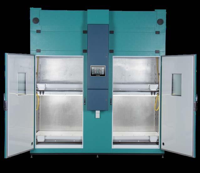
9 2 INSTALLATION 2.1 Installation Overview The following is an overview of the steps required to install the chamber in its final location. Each step on the list is covered in detail in the subsequent sections. 1. Determine the chamber location. 2. Uncrate and unpack the cabinet, machine compartment, and lifting kits. 3. Move the parts to the assembly location (if not in the final location). 4. Assemble the machine compartment onto the cabinet. 5. Move assembled chamber to the final location and level the chamber. 6. Make all required external and utility connections. 7. Start the system. 2.2 Determining Chamber Location The following considerations must be addressed before an appropriate location for the chamber can be determined: Clearances required for operation and service. Ambient environmental requirements. Access to required utility connections Clearance Requirements The chamber is shipped in three main pieces, the cabinet, the machine compartment and control panel. Whenever possible, install the machine compartment once the cabinet has been moved to its final location area. If it is necessary to fully assemble the growth chamber before moving it to its final location, ensure that all hallways, doorways, elevators, and other obstacles along the route to the final location can accommodate the cabinet dimensions of 100"W x 35½"D x 101"H (2540mmW x 900mmD x 2565mmH) (106 H [2692mm] with the service cover opened). In order to ensure normal operation and adequate space for servicing, the cabinet requires the following minimum clearances when installed: 39 (1000mm) above the cabinet with the lid closed. 2 (50mm) from the back of the cabinet. 2 (50mm) between cabinets (for side by side installations). April ENG-R00 2-1
10 Installation Ambient Environment Requirements The chamber requires a conditioned ambient environment to achieve the performance specifications. It is important to ensure that the room in which the growth cabinet is located adheres to these environmental conditions Temperature Conviron guarantees performance of the growth chamber for ambient temperature conditions between 59 F to 95 F (15 C and 35 C). Recommended ambient conditions are 70 F (21 C) at 50%RH Humidity The chamber will tolerate a range of ambient relative humidity conditions; however, performance will be limited by the following factors: Humidity is not controlled in chambers that are not equipped with the optional humidification and/or dehumidification devices. The resulting internal humidity will be a combination of the ambient conditions and internal conditions within the cabinet. The lowest achievable relative humidity in the growth cabinet with a dehumidification option will be a resultant dew point determined by the capability of the chamber. Ambient humidity conditions above the equivalent moisture content of 70 F (21 C) at 50%RH may cause a reduction in dehumidification performance. The highest achievable relative humidity in the growth chamber with a humidification option is resultant to a dew point of 77 F (25 C) unless stated otherwise. Ambient humidity conditions below the equivalent moisture content of 70 F (21 C) at 50%RH may cause a reduction in additive humidification performance. The range of operational ambient humidity is up to 90%RH (non-condensing) Altitude The maximum altitude is specified to be 7000ft. (2134 m) above sea level. 2-2 April ENG-R00
11 20 Series Installation Manual Utility Connection Requirements Table 2-1 Utility Connection Requirements Connection Used by Connection at Cabinet Specifications Standard/ Optional Electrical All electrical components Terminal block Refer to rating plate attached to the chamber. Standard Water Water cooled DX refrigeration system 1/2 OD copper pipe 50psi (3.45 Bar) minimum Standard Drain Cabinet drain 1 sch40 PVC Drain must not be elevated above cabinet drain connection. Standard Purified Water Humidification System 1/4 push-in fitting Water Quality: RO Water filtration: <2 microns or resistivity: 0.01 to 0.02 Meg ohm-cm Pressure and flow rate: 60 psi (4.2 bar) Maximum water usage: 1.06 US Gal/min (4 l/min) Optional Glycol/Water Hydronic refrigeration system 3/4 copper Designed to work with central chiller refrigeration system. Optional CO 2 Additive CO 2 control system 1/4 push-in fitting CO LPM Optional Refrigeration Remote outdoor aircooled (DXRAC) and outdoor air-cooled (OACU) condensing units Dependent on placement of cabinet and condensing unit Dependent on refrigeration system specifications and placement of cabinet and condensing unit Optional Alarm Contacts Central alarm contacts Terminal block Normally Open, Dry Contact, 5A maximum Standard Ethernet Communication (COMM) option: Central Management System RJ45 Ethernet port Straight Through Cable: For CM or building network connection Crossover Cable: For direct computer connection Standard April ENG-R00 2-3
, and the smaller crate contains the machine compartment and the control panel. Only qualified trades-people, i.e. electricians, plumbers, refrigeration mechanics, etc.")
12 Installation 2.3 Installation Procedure The 20 Series growth chambers are shipped in two crates. The larger crate contains the cabinet (Figure 2-1), and the smaller crate contains the machine compartment and the control panel. Only qualified trades-people, i.e. electricians, plumbers, refrigeration mechanics, etc. who have read and completely understood these instructions should perform the required installation work and according to local codes and regulations. Contact Conviron immediately if in doubt about safe and proper installation of the equipment. 2.4 Uncrate and Remove the Pallet The crate is attached to the shipping pallet with staples and screws. Dismantle and remove the crate from the shipping pallet. Figure 2-1 Cabinet Crate Do not leave any nails, staples, or screws protruding from the crating material to eliminate potential puncture injuries. Recycle, or properly dispose of, the crating material and shipping pallet. 2-4 April ENG-R00
, that secure the shipping bracket to the pallet.")
13 20 Series Installation Manual The following instructions describe removing the crating material for a chamber equipped with castors and for a shipping pallet constructed with lag bolts. Other chamber and pallet configurations differ slightly. If using a fork lift: 1. Remove the four lag screws, two on each side (Figure 2-2), that secure the shipping bracket to the pallet. Figure 2-2 Shipping Bracket Lag Screws 2. Position the fork lift centered with the center of the cabinet. 3. Slowly lift the cabinet off the shipping pallet, ensuring the cabinet is balanced on the forks and the cabinet is rising evenly. 4. Remove the shipping pallet and then proceed with installing the machine compartment. April ENG-R00 2-5

14 Installation If not using a fork lift: 1. Remove the eight lag screws, four on each side (Figure 2-3), from the ends of the pallet. Figure 2-3 Shipping Bracket & End Board Lag Screws 2. Remove the pallet end boards. 3. Position lifting devices, such as pallet jacks or small scissor jacks, under the shipping bracket and raise the cabinet slightly. 4. Remove the remains of the pallet. 5. Lower the cabinet and proceed with installation. 2-6 April ENG-R00


15 20 Series Installation Manual 2.5 Install the Machine Compartment Every order includes a lifting frame for use with a lifting device, such as a fork lift truck, to lift the machine compartment onto the cabinet and a set of handles to assist in positioning the machine compartment in its final position. Refer to the included Conviron document number , Operation and Maintenance of the MC- 20 Lift Frame, for the safe usage of the lifting frame. 1. If installing an ATC type chamber, connect the canopy wires before lowering the machine compartment completely. If installing a PGC chamber, plug the wire harness into the canopy after the machine compartment is installed. Figure 2-4 Canopy Wire Harness Connection 2. Install the plastic plug covers into the holes used to attach the lifting frame, four on each side. Figure 2-5 Plug Covers & Draw Latches 3. Close all eight draw latches, four on the front and four on the rear, to secure the machine compartment to the chamber. April ENG-R00 2-7
 on the back")


16 Installation 2.6 Install the Control Panel 1. Lift the Control Panel onto the chamber and rest the bracket (Figure 2-6, Figure 2-7) on the back of the panel on the edge of the cabinet. 2. Secure the bracket to the cabinet with the included 8-32 x ½ screws. Figure 2-6 Flush Mount Bracket Figure 2-7 Extended Height Bracket 3. Open the Control Panel door, locate and align the four mounting holes, and then install the ¼ - 20 x ¾ bolts. 4. Connect the cables from the Control Panel to the machine compartment (Figure 2-8). Figure 2-8 Control Panel Electrical Connections 2-8 April ENG-R00

17 20 Series Installation Manual 5. Install the front covers onto the machine compartment with the included 8-32 x ½ screws to complete the installation of the Control Panel (Figure 2-9). Figure 2-9 Installed Control Panel Make all the mechanical connections to the ventilation, water and drainage systems, and then re-install the covers before making any external electrical connections. 2.7 Level the Chamber When in position in its final location, it is critical that the chamber is leveled for stability and proper operation before making the utility connections. Levelers are located in each corner of the cabinet, and in the middle, both front and back (Figure 2-10). Use an open ended wrench on the flats near the base of the threaded levelers to level the cabinet. Figure 2-10 Chamber Levelers April ENG-R00 2-9
18 Installation 2.8 Install the Floor Anchors The floor anchors are only intended to prevent the chamber from moving during normal operation and maintenance. They are not rated for seismic protection. Concrete floor anchors must be installed according to the manufacturer s instructions. Once the chamber is positioned and leveled, the floor anchors, located at both ends of the chamber, must be bolted to the floor. Figure 2-11 Floor Anchors 1. Remove the angled floor plate, and then mark and drill the anchor holes. 2. Re-install the angled floor plate, and then bolt the plate to the floor. Make all the mechanical connections to the ventilation, water and drainage systems and re-install the covers BEFORE making any electrical connections April ENG-R00

19 20 Series Installation Manual 2.9 Connect the Drain Line The chamber is equipped with a drain, terminating in a 1 (2.5 cm) ID hose fitting located in the right front corner of the cabinet. Connect this drain to a building floor drain or drainage system. Figure 2-12 Drain Line Low temperature chambers are equipped with an additional ½ (12.25 cm) SCH40 PVC drain located behind the machine compartment. Connect this drain to a building floor drain or drainage system Connect the Cooling Lines 1. Remove any caps installed on the copper water lines. 2. Connect the supply water line to the Water IN copper pipe. 3. Connect the return water line to the Water OUT copper pipe. 4. Ensure the bypass valve is closed by turning the handle clockwise. Water IN Water OUT Figure 2-13 Cooling Lines April ENG-R


20 Installation 2.11 Connect the Internal Wiring Harnesses Aspirator 1. Attach the cable to bottom of the aspirator. 2. Ensure the other end of the cable is connected to the chamber wall outlet. Figure 2-14 Aspirator Connections Flex Canopy 1. Attach the canopy power cables to the bottom of the canopy. 2. Ensure the other ends of the cables are secured to the clip on the front wall. Figure 2-15 Flex Canopy Connections 2-12 April ENG-R00
 2.12.")


21 20 Series Installation Manual 2.12 Connect the Option Systems (if so equipped) Auto Watering Irrigation System Line Attach the water supply line to the ½ schedule 40 PVC inlet on the shut-off valve. Figure 2-16 Auto-Watering Irrigation Spray Nozzle Humidifier Line Install ¼ OD tubing from the water supply to the inlet on the shut-off valve. Figure 2-17 Spray Nozzle Humidifier CO 2 Supply Line Install ¼ OD tubing from theco2 supply to the inlet on the regulator. Figure 2-18 CO 2 Supply April ENG-R
 sheet metal duct from")
22 Installation Exhaust Vent The external exhaust collar is located in the right rear corner of the machine compartment Install a 4 (100mm) sheet metal duct from the exhaust collar to the building ventilation system, or to an external vent. Figure 2-19 Exhaust Vent 2-14 April ENG-R00

23 20 Series Installation Manual 2.13 Connect the Electrical Lines Ensure that power to the cable from the main breaker panel to the chamber is OFF, and locked out or tagged out, before making any electrical connections at the chamber. Check all wire connections inside the control panel to ensure the connections have not come loose in transit. Tighten any loose connections to the torque specifications of each component listed on the electrical drawings. 1. Ensure the main power disconnect switch is OFF. 2. Open the control panel door, and then install the power cable into the cabinet. 3. Install ferrules onto the ends of the power, neutral, and ground wires. 4. Connect the ground wire to the ground terminal block. 5. Connect the neutral wire to the neutral terminal block 6. Connect the 3 wires to the LI, L2, and L3 terminals on the main power disconnect switch. Figure 2-20 Electrical Connections April ENG-R
24 Installation 2-16 April ENG-R00
25

26 Conviron Head Office Winnipeg, Canada conviron.com Conviron Europe Ltd. Cambridgeshire, UK conviron.co.uk Conviron China Shanghai, China conviron.cn Conviron US Pembina, USA conviron.com Conviron Germany GmbH Berlin, Germany conviron.de Conviron Australia Melbourne, Australia conviron.com.au ISO ENG-R00, April Controlled Environments Limited. Conviron is a registered trademark of Controlled Environments Limited. All other trademarks are the property of their respective owners. Information is subject to change without written notice.
E7/2 and E8 Chambers. Installation Manual ENG R00
 E7/2 and E8 Chambers Installation Manual 283342-ENG R00 E7/2 and E8 Chambers Installation Manual Please read these instructions carefully and completely before operating the unit. Conviron Document Number
A2000 Chamber INSTALLATION, OPERATION, AND MAINTENANCE MANUAL ENG R01
 A2000 Chamber INSTALLATION, OPERATION, AND MAINTENANCE MANUAL 278061 ENG R01 A2000 Chamber Installation, Operation, and Maintenance Manual Please read these instructions carefully and completely before
BDR16 User Manual ENG R00
 BDR16 User Manual 287849-ENG R00 BDR16 User Manual Please read these instructions carefully and completely before operating the chamber. Conviron Document Number 287849-ENG, Revision 00 Published by:
MIST SYSTEM CONFIGURATION AND PROGRAMMING INSTRUCTIONS R03
 MIST SYSTEM CONFIGURATION AND PROGRAMMING INSTRUCTIONS 261134R03 MIST SYSTEM CONFIGURATION AND PROGRAMMING INSTRUCTIONS PLEASE READ THESE INSTRUCTIONS CAREFULLY AND COMPLETELY BEFORE OPERATING. Published
Reach-In. PLanT GROWTh. Reach-In
 E7 Reach-In PLanT GROWTh Reach-In E7 Reach-In PLANT GROWTH Product Overview/Applications Conviron s E7 plant growth chamber is a compact yet highly configurable unit that is suitable for a wide variety
Installation Manual PS-225 & PS-275
 Installation Manual PS-225 & PS-275 Table of Contents Pre-Uncrating Checklist... 1 Verifying System Requirements... 2 Verifying System Direction... 2 Verifying the Electrical Requirements... 2 Removal
DISHWASHER INSTALLATION GUIDE SPECIFICATIONS, INSTALLATION, AND MORE
 DISHWASHER INSTALLATION GUIDE SPECIFICATIONS, INSTALLATION, AND MORE COVE DISHWASHER Contents 3 Cove Dishwasher 4 Specifications 7 Door Panel 9 Installation 15 Troubleshooting Features and specifications
Plant Growth Chamber MPGR14
 Plant Growth Chamber Product Overview/Applications The provides a 14 ft2 growth area and a 58 inch growth height making this chamber suitable for a range of applications including plant science, bioengineering,
Installation Manual PS-200 & PS-201
 Installation Manual PS-200 & PS-201 Table of Contents Pre-Uncrating Checklist... 1 Verifying System Requirements... 2 Verifying System Direction... 2 Verifying the Electrical Requirements... 2 Removal
INSTALLATION INSTRUCTIONS
 INSTALLATION INSTRUCTIONS BUILT-IN BOTTOM MOUNT REFRIGERATOR/FREEZER DBRTGK72SS-GRILLE KIT (FOR designer SERIES ONLY) VIKING RANGE CORPORATION 111 Front Street Greenwood, Mississippi (MS) 38930 USA (662)
Installation and Operation Manual For Hunter Ceiling Fans
 Installation and Operation Manual For Hunter Ceiling Fans 1 2 CONGRATULATIONS! Your new Hunter ceiling fan is an addition to your home or office that will provide comfort and performance for many years.
Installation Instructions
 Installation Instructions For Free Standing NoFrost Combined Refrigerator-Freezers CS 1660 7082 653-00 PLEASE READ AND FOLLOW THESE INSTRUCTIONS These instructions contain Warning and Caution statements.
PME. Series Enclosures. Battery Enclosure (BE) Field Upgrade Installation Instructions. Effective: January, Alpha Technologies
 Field Upgrade Installation Instructions. Effective: January, Alpha Technologies") PME Series Enclosures Battery Enclosure (BE) Field Upgrade Installation Instructions Effective: January, 2004 Alpha Technologies Power Alpha Technologies. Protecting The Power in Communications. Preface
PME Series Enclosures Battery Enclosure (BE) Field Upgrade Installation Instructions Effective: January, 2004 Alpha Technologies Power Alpha Technologies. Protecting The Power in Communications. Preface
INSTALLATION INSTRUCTIONS
 INSTALLATION INSTRUCTIONS BUILT-IN BOTTOM MOUNT REFRIGERATOR/FREEZER BRTGK72SS-GRILLE KIT (FOR PROFESSIONAL SERIES ONLY) VIKING RANGE CORPORATION 111 Front Street Greenwood, Mississippi (MS) 38930 USA
1-866-PENNERS
 Cascade Premier and Elite Premier Bathing Systems with Aqua-Aire Installation / Assembly Instructions Premier Elite Premier PENNER PATIENT CARE, INC Box 523 / 102 Grant St. Aurora, NE 68818 360745P Revision
Instruction Sheet. DANGER Indicates a potentially or imminently hazardous situation which, if not avoided, will result in death or serious injury.
 Instruction Sheet DOC306.53.00742 Safety information Please read this entire document before unpacking, setting up or operating this equipment. Pay attention to all danger and caution statements. Failure
PGW36. WALk-IN PLANT GROWTH. WALk-IN
 PGW36 WALk-IN PLANT GROWTH WALk-IN PGW36 walk-in PLANT GROWTH Product Overview/Applications The PGW36 equips the researcher with a walk-in environment which is accessible from four large doors two on the
Design Guide Fully Integrated Models - 36"
 Design Guide 2008 Fully Integrated Models - 36" Welcome Liebherr's engineering excellence in Germany provides the largest selection of freezers, refrigerators and wine refrigerators worldwide. Liebherr-appliances
WARNING: Warns of health hazards and identifies possible risks of injury. CAUTION: Indicates possible dangers to the machine or other objects.
 VBT3ASV USER GUIDE SAFETY INFORMATION About this user guide Read this user guide completely before using the machine. Keep this user guide for reference. If you pass your machine on to third parties, it
Installation Guide. 15 W. Undercounter/Freestanding Nugget Ice Machine U L. Viking Range, LLC. 111 Front Street
 Installation Guide Viking Range, LLC 111 Front Street Greenwood, Mississippi 38930 USA (662) 455-1200 For product information, call 1-888-(845-4641) or visit our web site at vikingrange.com in the US or
Installation Instructions
 Installation Instructions For Fully Integrated NoFrost Combined Refrigerator-Freezers HCB 1560/1561 7084 429-00 Important Please read and follow these instructions These instructions contain Danger, Warning
PRO 48 INSTALLATION INSTRUCTIONS
 PRO 48 INSTALLATION INSTRUCTIONS CONTENTS PRO 48 Installation Recommendations 3 PRO 48 Overall Dimensions 4 PRO 48 Installation Specifications 5 PRO 48 Installation Instructions 6 PRO 48 Installation Checklist
Installation. 15 W. Undercounter/Freestanding Ice Machine FGIM515 / CFGIM515 FPIM515 / CFPIM515
 Installation 15 W. Undercounter/Freestanding Ice Machine FGIM515 / CFGIM515 FPIM515 / CFPIM515 TABLE OF CONTENTS Warnings & Important Safety Instructions 3 Dimensions (Professional) 5 Dimensions (Custom
Installation. Leveling
 Your refrigerator was packed carefully for shipment. Remove and discard shelf packaging and tape. Do not remove the serial plate. Location Do not install refrigerator near oven, radiator or other heat
CD30 / CD30E INDUSTRIAL DEHUMIDIFIER OWNER S MANUAL
 CD30 / CD30E INDUSTRIAL DEHUMIDIFIER OWNER S MANUAL www.eipl.co.uk Page 1 of 12 CD30 PACKAGE CONTENTS Item Description Quantity 1133500 Dehumidifier 1 3014338 PVC tube 12mm I/D 3 M 3086101 Jubilee clip
Refrigerator BRFB1920SS BRFB1900FBI BRFB1920FBI
 Refrigerator BRFB1920SS BRFB1900FBI BRFB1920FBI Table of Contents Symbols and Their Meanings... 3 Product weight... 5 Load bearing capacity of the doors... 5 Climate class... 5 Product Information:...
INSTALLATION MANUAL COMFORT...BUILT TO LAST. 9,000, 12,000 and 18,000 BTU SINGLE-ZONE DUCTLESS MINI-SPLIT SYSTEM Heat Pump
 COMFORT...BUILT TO LAST 9,000, 12,000 and 18,000 BTU SINGLE-ZONE DUCTLESS MINI-SPLIT SYSTEM Heat Pump INSTALLATION MANUAL INDOOR UNIT: 1PAMSH09-SZW-14.5 1PAMSH09-SZW-15 1PAMSH12-SZW-15 1PAMSH18-SZW-15
Installation Instructions
 Installation Instructions For Fully Integrated NoFrost Combined Refrigerator-Freezers HCB 1560/1561 HC 1550 7084 327-00 Important Please Read and Follow these Instructions These instructions contain Danger,
Installation and Operation Manual For Hunter Ceiling Fans /16/2004
 Installation and Operation Manual For Hunter Ceiling Fans 1 2 CONGRATULATIONS! Your new Hunter ceiling fan is an addition to your home or office that will provide comfort and performance for many years.
Please read the following installation instructions first after purchasing this product or transporting it to another location.
 9 Installation Overview Please read the following installation instructions first after purchasing this product or transporting it to another location. 1 Unpacking your refrigerator 2 Choosing the proper
Installation. Built-in Full Height Wine Cellar VCWB301
 Installation Built-in Full Height Wine Cellar VCWB301 Table of Contents Warnings & Important Information _ 3 Dimensions _ 5 Specifications _ 6 Cutout Dimensions 7 Cabinet Information _ 8 Cabinet Information
F6102 Installation & Operating Instructions for the Parrotuncle Owner s Installation,Manual WARNING: SHUT POWER OFF AT FUSE OR CIRCUIT BREAKER
 CAUTION READ INSTRUCTIONS CAREFULLY FOR SAFE INSTALLATION AND FAN OPERATION. IF UNSURE CONSULT A QUALIFIED ELECTRICIAN F6102 THANK YOU FOR YOUR PURCHASE Thank you for purchasing this quality product. To
Cascade Premier and Elite Premier Bathing Systems with Aqua-Aire Installation / Assembly Instructions
 Cascade Premier and Elite Premier Bathing Systems with Aqua-Aire Installation / Assembly Instructions Premier Elite Premier PENNER PATIENT CARE, INC Box 523 / 102 Grant St. Aurora, NE 68818 360745P Revision
Viking Installation Guide
 Viking Installation Guide Viking Range, LLC 111 Front Street Greenwood, Mississippi 38930 USA (662) 455-1200 For product information, call 1-888-(845-4641) or visit the Viking Web site at vikingrange.com
Models: GW/R-T GW/R-2-T GW/R-3-T
 Part# GW/R-T-OM 1/12/04 TN Models: GW/R-T GW/R-2-T GW/R-3-T This manual contains important information concerning the installation and operation of the gun washers listed above. Read manual thoroughly
Installation & Operating Guide
 5-036 HOT WATER TANK Installation & Operating Guide Read all instructions thoroughly. Keep this guide for future reference. Proof of purchase is required for Warranty. Staple receipt or proof of purchase
ACQUITY UPLC HT Column Heater Instructions
 ACQUITY UPLC HT Column Heater Instructions Note: This document is an addendum to Revision C of the ACQUITY UPLC System Operator s Guide. Contents: Topic Page Overview 1 Connecting the cable 4 Installing
Top Control Dishwasher
 INSTALLATION GUIDE Top Control Dishwasher NS-DWH2BS8/NS-DWH2SS8/NS-DWR2BS8/NS-DWR2WH8/NS-DWR2SS8 Before using your new product, please read these instructions to prevent any damage. Contents Introduction......................................................................................................
TABLE OF CONTENTS. NOTE: Read the entire instruction manual before starting the installation. TROUBLESHOOTING... 13
 R 410A Duct Free Split System Air Conditioner and Heat Pump Product Family: DFS4(A/H) System, DFC4(A/H)3 Outdoor, DFF4(A/H)H Indoor NOTE: Read the entire instruction manual before starting the installation.
INSTALLATION. Glass Panel Doors (select models) CAUTION
 CAUTION") Location Do not install refrigerator near oven, radiator or other heat source. If not possible, shield refrigerator with cabinet material. Do not install where temperature falls below 55 F (13 C) or rises
Location Do not install refrigerator near oven, radiator or other heat source. If not possible, shield refrigerator with cabinet material. Do not install where temperature falls below 55 F (13 C) or rises
Hoshizaki America, Inc.
 Hoshizaki America, Inc. Modular Crescent Cuber Models KM-1340MAH KM-1340MWH KM-1340MRH A Superior Degree of Reliability INSTRUCTION MANUAL www.hoshizaki.com Issued: 8-11-2005 IMPORTANT Only qualified service
Installation Instructions
 Installation Instructions For Fully Integrated NoFrost Combined Refrigerator-Freezers HC 2060/2061 7082 485-00 Important PLEASE READ AND FOLLOW THESE INSTRUCTIONS These instructions contain Warning and
Installation Instructions
 Installation Instructions For Free Standing NoFrost Combined Refrigerator-Freezers CS 1660 7084 203-00 Important Please Read and Follow these Instructions These instructions contain Danger, Warning and
Concepts Serving Systems
 Concepts Serving Systems Installation Manual Please read this manual completely before attempting to install or operate this equipment! Notify carrier of damage! Inspect all components immediately. February
Design Guide 2008 Fully Integrated Models 24" and 48"
 Design Guide 2008 Fully Integrated Models 24" and 48" 7082440-01 Welcome Liebherr's engineering excellence in Germany provides the largest selection of freezers, refrigerators and wine refrigerators worldwide.
Dishwasher Installation Instructions DW 24XT/DW 24XV
 Dishwasher Installation Instructions DW 24XT/DW 24XV Installation Instructions Dishwasher BEFORE YOU BEGIN Read these instructions completely and carefully. IMPORTANT Observe all governing codes and ordinances.
Page 1 of 18. Part# /5/2013
 Part# 1002655-06 8/5/2013 This manual contains important information concerning the installation and operation of the gun washers listed above. Read manual thoroughly and keep for future reference INSTRUCTIONS
EBAC MODEL PD120 INDUSTRIAL DEHUMIDIFIER OWNER S MANUAL
 EBAC MODEL PD120 INDUSTRIAL DEHUMIDIFIER OWNER S MANUAL www.eipl.co.uk UNPACKING Carefully remove the PD120 dehumidifier unit from its transit box and visually check for signs of transit damage. If there
WAILEA OWNER S MANUAL
 WAILEA OWNER S MANUAL The blades in each pack are matched for equal weight to assure smooth fan operation. If more than one fan is being installed, be careful not to mix blades from different cartons.
SUTTON 52 CEILING FAN
 SUTTON 52 CEILING FAN MODELS #50188, 50189, 50190 Español p. 19 Questions, problems, missing parts? Before returning to your retailer, call our customer service department at 1-877-361-3883, Monday - Thursday,
Installation Instructions
 Installation Instructions KFN 9855 ide en - CA Installation, repair and maintenance work should be performed by a Miele authorized service technician in accordance with national and local safety regulations
Integrated Refrigeration
 INSTALLATION GUIDE Integrated Refrigeration Contents Integrated Refrigeration....................... 3 Model Specifications.......................... 4 Site Preparation.............................. 6
INSTALLATION AND OPERATION MANUAL STEAM COIL BASE CONVECTION STEAMER MODEL SCX-16
 INSTALLATION AND OPERATION MANUAL STEAM COIL BASE CONVECTION STEAMER MODEL SCX-16 CROWN FOOD SERVICE EQUIPMENT LTD. 70 OAKDALE ROAD, DOWNSVIEW, (TORONTO), ONTARIO, CANADA, M3N 1V9 TELEPHONE: (416) 746-2358,
Installation Instructions
 Installation Instructions For NoFrost Combined Refrigerator-Freezers with IceMaker CS/CBS 20 7084 337-00 Important Please Read and Follow these Instructions These instructions contain Danger, Warning and
Hoshizaki America, Inc.
 Hoshizaki America, Inc. Modular Crescent Cuber Models KM-501MAH KM-501MWH KM-501MRH A Superior Degree of Reliability INSTRUCTION MANUAL www.hoshizaki.com Issued: 2-13-2006 IMPORTANT Only qualified service
ELSTON 52 CEILING FAN
 ELSTON 52 CEILING FAN MODEL #10290 Español p. 21 Questions, problems, missing parts? Before returning to your retailer, call our customer service department at 1-877-361-3883, Monday - Thursday, 8 am -
Aqua-Aire Sit-Bath System 6300 Installation / Assembly Instructions
 Aqua-Aire Sit-Bath System 6300 Installation / Assembly Instructions PENNER PATIENT CARE, INC Box 523 / 102 Grant St. Aurora, NE 68818 350745 Rev F 02/23/11 1-866-PENNERS 1-866-736-6377 1-800-732-0717 E-mail
DUVAL 52 CEILING FAN MODELS #50201, Español p. 19 LISTED FOR DAMP LOCATION
 DUVAL 52 CEILING FAN MODELS #50201, 50206 Español p. 19 LISTED FOR DAMP LOCATION Questions, problems, missing parts? Before returning to your retailer, call our customer service department at 1-877-361-3883,
TOUCHDOWN 48 CEILING FAN
 TOUCHDOWN 48 CEILING FAN MODEL #50205 Español p. 20 Questions, problems, missing parts? Before returning to your retailer, call our customer service department at 1-877-361-3883, Monday - Thursday, 8 am
Installation & Operating Guide
 HOT WATER DISPENSER Installation & Operating Guide Read all instructions thoroughly. Keep this guide for future reference. Proof of purchase is required for Warranty. Staple receipt or proof of purchase
Quick Start Installation Guide
 Quick Start Installation Guide Nortec EL Electrode Steam Humidifier Overview Mounting Installation Requirements Standard Mounting Steam Distribution Installation Requirements Plumbing Water and Drainage
Dehumidifier Owner s Manual Read and save these instructions before use
 Dehumidifier Owner s Manual Read and save these instructions before use Model: DH45W For product inquiries or support: www.jmatek.com Customer Support: 1-800-474-2147 E-mail us at: usinfo@jmatek.com ERGY
Design Guide 2008 Built In Models 30" and 60"
 Design Guide 2008 Built In Models 30" and 60" Welcome Liebherr's engineering excellence in Germany provides the largest selection of freezers, refrigerators and wine refrigerators worldwide. Liebherr-Hausgeräte
Technical Data. Name: ERIKA Automat fully automatic machine to divide and to round dough pieces of the same size
 AUTOMAT MANUAL 1 Technical Data Name: ERIKA Automat fully automatic machine to divide and to round dough pieces of the same size Type Divisions Dough Portions (in ounces) Plate Nos. 3 30 1.0 3.5 #35 4/40A
Design Guide 2008/2009 Fully Integrated Models 24" and 48"
 Design Guide 2008/2009 Models 24" and 48" Welcome Liebherr's engineering excellence in Germany provides the largest selection of freezers, refrigerators and wine refrigerators worldwide. Liebherr appliances
 1600W WALL MOUNTED HAIR DRYER COI0016_V3_070814 USE & CARE MANUAL www.corbyofwindsor.com SECTION 01 These notes must be read before installation These instructions are for your safety. Please read through
Installation Instructions Remote Blowers
 Installation Instructions Remote Blowers Models: REMP3, REMP16 Suitable for use in a household cooking area. Suitable for use with solid state controls. To complete this blower, a Dacor hood assembly or
Plant Growth Room MBDW Walk In Room
 Plant Growth Room Product Overview/Applications The MBDW series walk-in chamber is based on a modular platform available in increments of 40ft2 (3.7m2). These units offer a precise chamber environment
BUILT-IN DISHWASHER INSTALLATION INSTRUCTIONS
 BUILT-IN DISHWASHER INSTALLATION INSTRUCTIONS PLEASE READ COMPLETE INSTRUCTIONS BEFORE YOU BEGIN LEAVE INSTALLATION INSTRUCTIONS AND USER'S GUIDE WITH OWNER ALL ELECTRIC WIRING AND PLUMBING MUST BE DONE
USE & CARE MANUAL COMPACT ELECTRIC FIREPLACE SUITE. CO9158 V1_301012
 COMPACT ELECTRIC FIREPLACE SUITE CO9158 V1_301012 USE & CARE MANUAL www.adamfires.co.uk SECTION 01 These notes must be read before installation These instructions are for your safety. Please read through
Pulldown Kitchen Faucet
 P25200 1 of 7 Thank You For Choosing Kallista We appreciate your commitment to Kallista quality products. Please take a moment to review this manual before you install your Kallista product. If you encounter
Design Guide Built In Models 24" and 48"
 Design Guide 2017-01 Built In Models 24" and 48" Welcome Liebherr's engineering excellence in Germany provides the largest selection of freezers, refrigerators and wine refrigerators worldwide. Liebherr
e Bath Fan with Light User s Guide
 e Bath Fan with Light User s Guide abfl100rnl, BFL125RNL Item Stock Number(s): BFL100RNL, BFL125RNL IMPORTANT INSTRUCTIONS - OPERATING MANUAL READ AND SAVE THESE INSTRUCTIONS READ CAREFULLY BEFORE ATTEMPTING
Gerber Innovations M Series Laser. Site Preparation & Installation Manual
 Gerber Innovations M Series Laser Site Preparation & Installation Manual Copyright Notice COPYRIGHT 2011 Gerber Innovations, Inc. All Rights Reserved. This document may not be reproduced by any means,
Premier External TD. Installation Manual INS352-3
 Premier External TD Installation Manual INS352-3 1. Accessing the Unit 1 2 Remove the top cap and loosen screw (screw retained in wall plate). Push up head unit and remove. 3 Use a flat head screwdriver
Installation Instructions
 Instructions For Fully Integrated NoFrost Combined Refrigerator-Freezers HC 1540/1541 7084 433-00 Important Please read and follow these instructions These instructions contain Danger, Warning and Caution
INSTALLATION GUIDE Dual Fuel Ranges
 INSTALLATION GUIDE Dual Fuel Ranges Contents Wolf Dual Fuel Ranges......................... 3 Safety Instructions............................ 4 Dual Fuel Range Specifications.................. 5 Dual Fuel
Installation Instructions
 Installation Instructions For NoFrost Combined Refrigerator-Freezers with IceMaker CS 2060, CS 2061 7084 339-00 Important Please Read and Follow these Instructions These instructions contain Danger, Warning
Built-In Dishwasher. Installation Instructions. BEFORE YOU BEGIN Read these instructions completely and carefully. IMPORTANT The dishwasher MUST be
 Installation Instructions Built-In Dishwasher If you have questions, call 800.GE.CARES (800.432.2737) or visit our website at: www.ge.com BEFORE YOU BEGIN Read these instructions completely and carefully.
INVERTER SPLIT - TYPE
 INVERTER SPLIT - TYPE ISSUE No 2 DATE 04/09/08 P/No 2020323A2868 CONTENTS SAFETY PRECAUTIONS Warning 2 Operating temperature 2 BEFORE INSTALLATION Tools needed for installation 3 Items required for installing
Installation Instructions
 Installation Instructions For Fully Integrated NoFrost Combined Refrigerator-Freezers HC 2060/2061 HCB 2060/2061 7084 349-00 Important Please Read and Follow these Instructions These instructions contain
Installation Instructions. For the 18 Built-In Dishwasher and Front Color Panels
 Installation Instructions For the 18 Built-In Dishwasher and Front Color Panels Printed in USA 154232102 Before You Begin DO NOT INSTALL DISHWASHER UNTIL YOU HAVE READ ALL INSTRUCTIONS. FOR YOUR SAFETY,
INSTALLATION INSTRUCTIONS
 OVER THE RANGE CONVECTION MICROWAVE OVEN INSTALLATION INSTRUCTIONS Please read all instructions thoroughly before installing the Over the Range Microwave Oven/Hood System. Two people are recommended to
GE Monogram. Installation. Instructions. Stainless Steel Bottom Mount Built-In Refrigerators. Models ZICS36N RH ZICS36N LH
 GE Monogram Installation Instructions Stainless Steel Bottom Mount Built-In Refrigerators Models ZICS36N RH ZICS36N LH Before you begin - Read these instructions completely and carefully. IMPORTANT - Save
Zip Econoboil 1.5 litre White Zip Econoboil 3.0 litre White Zip Econoboil 5.0 litre White Zip Econoboil 7.
 Zip Econoboil Installation and Operating Instructions 301042 Zip Econoboil 1.5 litre White 303042 Zip Econoboil 3.0 litre White 305042 Zip Econoboil 5.0 litre White 307042 Zip Econoboil 7.5 litre White
B.C.S. Shop Heaters 26, 30 & 36 (36 shown)
") BIOMASS COMBUSTION SYSTEMS, INC. 67 MILLBROOK ST., SUITE 502 WORCESTER, MA 01606 508-798-5970 - FAX 508-798-5971 B.C.S. Shop Heaters 26, 30 & 36 (36 shown) INSTALLATION MANUAL HAND FIRED SYSTEMS 8-09 Biomass
BIOMASS COMBUSTION SYSTEMS, INC. 67 MILLBROOK ST., SUITE 502 WORCESTER, MA 01606 508-798-5970 - FAX 508-798-5971 B.C.S. Shop Heaters 26, 30 & 36 (36 shown) INSTALLATION MANUAL HAND FIRED SYSTEMS 8-09 Biomass
Installation Instructions
 Installation Instructions For Fully Integrated NoFrost Combined Refrigerator-Freezers HC 2062 HCB 2062 HC/HCB 20 7082 373-00 Important PLEASE READ AND FOLLOW THESE INSTRUCTIONS These instructions contain
HE120, HE160 Humidifier Installation Kit
 HE120, HE160 Humidifier Installation Kit INSTALLATION INSTRUCTIONS WELCOME To the comfortable world of humidified air. When you use your Honeywell humidifier, you notice that your skin is not as dry, and
ELECTRIC WALL HANGING FIREPLACE SUITE FUI0005_V2_ USE & CARE MANUAL
 ELECTRIC WALL HANGING FIREPLACE SUITE FUI0005_V2_181016 USE & CARE MANUAL SECTION 01 Read ALL the instructions before use. These instructions are for your safety. Please read through them thoroughly before
DR-180 Through the Wall Exhaust Fan PRODUCT MANUAL & INSTALLATION GUIDE
 DR-180 Through the Exhaust Fan PRODUCT MANUAL & INSTALLATION GUIDE READ AND SAVE THESE INSTRUCTIONS READ CAREFULLY BEFORE ATTEMPTING TO ASSEMBLE, INSTALL, OPERATE OR MAINTAIN THE PRODUCT DESCRIBED. PROTECT
Ceiling Mount Air Purification System
 Ceiling Mount Air Purification System HA-CMP-G2-R/HA-CMP-G2-OV Owner s Manual Table of Contents HealthyAir Series 1219 Filters 1 Important Safety Instructions 2 Technical Specifications 3 Packaging Reference
 2000W FOLDING HAIR DRYER COI0034_V3_181116 USE & CARE MANUAL www.corbyofwindsor.com SECTION 01 These instructions must be read before use These instructions are for your safety. Please read through them
Installation Instructions
 Installation Instructions Over the Range Microwave Oven PVM88 Questions? Call -800-56-44 or Visit our Website at: GEAppliances.ca BEFORE YOU BEGIN Read these instructions completely and carefully. IMPORTANT
MODULAR CRESCENT CUBER
 Reliability is a beautiful thing TM MODULAR CRESCENT CUBER KMD-700MAH KMD-700MWH KMD-700MRH KMD-900MAH KMD-900MWH KMD-900MRH INSTRUCTION MANUAL ISSUED: APRIL 24, 2003 REVISED: JAN. 3, 2008 IMPORTANT Only
INSTALLATION MANUAL REFRIGERATION IK008 INTEGRATION KIT WTB4600, KTM4602, WTB5400, KTM5402, WBE4500, KBM4502, WBE5300, KBM5302, WFB4204, WRB5004
 INSTALLATION MANUAL REFRIGERATION IK008 INTEGRATION KIT WTB4600, KTM4602, WTB5400, KTM5402, WBE4500, KBM4502, WBE5300, KBM5302, WFB4204, WRB5004 2 electrolux.com.au CONGRATULATIONS Congratulations and
IB 835. Installation Manual. Integrated Bidet Toilet TABLE OF CONTENTS
 IB 835 Installation Manual Integrated Bidet Toilet Cautions before installation Water supply should have a minimum water pressure of 10 psi For smooth drainage, water pressure must stay at its required
ORIGINAL INSTRUCTIONS
 WARNING: Read the instructions before using the machine. POWER WASHER MODEL NO: JETSTAR 1950 PART NO: 7336010 OPERATION & MAINTENANCE INSTRUCTIONS ORIGINAL INSTRUCTIONS LS0617 - ISS 3 INTRODUCTION Thank
Installation Instructions
 Installation Instructions Over the Range Microwave Oven BEFORE YOU BEGIN (Read these instructions completely and carefully.) IMPORTANT IMPORTANT Save these instructions for local inspector s use. Observe
USE & CARE MANUAL CONTEMPORARY ELECTRIC FIREPLACE SUITE. CO9144 V3_080714
 CONTEMPORARY ELECTRIC FIREPLACE SUITE CO9144 V3_080714 USE & CARE MANUAL www.adamfires.co.uk SECTION 01 Read ALL the instructions before use. These instructions are for your safety. Please read through
Installation Instructions T 9822 Gas Dryer. en - US, CA. To prevent accidents
 Installation Instructions T 9822 Gas Dryer To prevent accidents en - US, CA and appliance damage read these instructions before installation or use. M.-Nr. 07 431 110 2 WARNING For your safety the information