intelligent TECHNOLOGIES iflow HYDRONIC FURNACE NEW GENERATION OF HEATING & COOLING
|
|
|
- Cleopatra Walker
- 5 years ago
- Views:
Transcription


1 intelligent TECHNOLOGIES iflow HYDRONIC FURNACE NEW GENERATION OF HEATING & COOLING
2 Table of Contents: Introduction Safety. 3 Summary of air handler. 4 Technician checklist. 4 Product Description Components.. 5 Standard features and benefits... 6 Equipment selection and sizing... 9 Suitable Applications (Choosing the correct heat source) 11 Installation Location requirements and clearances Dimensions.. 12 Installation examples 13 Boiler Piping 15 Domestic Piping.. 16 Circulating Pump. 16 Electrical requirements and making connections. 17 Temperature sensors 17 Start Up Procedure. 17 Flushing the heat exchanger.. 18 Sequence of operation 18 Service and Maintenance Maintenance 19 Checking temperature sensors..19 Configuring and operating control Wiring Diagram. 25 Troubleshooting Fault Codes and Explanations 28 Problems and Solutions Blower Performance Parts List.. 30 Warranty Warranty Information 39 Contact information 39 2


3 Introduction 1. Introduction Safety Ensure the instructions and requirements provided in this manual are read and understood before installation. Failure to comply with these instructions can cause product and property damage, serious injury or death. Pay attention to the following safety symbols and words: DANGER: indicates an imminently hazardous situation, which if not avoided, will result in death or serious injury. WARNING: indicates a potentially hazardous situation, which if not avoided, could result in death or serious injury. CAUTION: indicated a potentially hazardous situation, which if not avoided, may result in minor or moderate injury. It is also used to alert against unsafe practices and hazards involving property damage. 2. Summary of air handler When considering a combined space and water heating system, the iflow hydronic furnaces are designed to deliver the highest performance rating of any air handler regardless of hot water source when tested to CSA s P.9 11 combined systems efficiency standard. This unique hydronic furnace is built for use in residential and commercial applications. 3

4 3. Installer checklist Be sure all system components and piping are free of air prior to start up Recommended to install purge valves between the air handler and the water heater s isolation valves If being connected to domestic piping creating an open system, make sure all piping, components and solder are lead free and approved for potable use CAUTION Return air openning shall not be installed on the back side of unit IMPORTANT The maximum ambient temperature must not exceed 122 F(50 C) Ensure fan assembly is clear of any obstruction Check that air filter is installed upstream of air conditioning coil If the appliance is installed with air conditioning, the A/C refrigerant charge and system operation must be verified by a certified/ licensed mechanic prior to commissioning IMPORTANT A field fabricated auxiliary drain pan with pipe is recommended in all configurations. 4


5 Product Description 1) Components Cabinet: All cabinets are made of strong, high quality, durable heavy gauge galvanized steel. The inside of the cabinet is fully insulated with ½ Polyethylene sheets or 1 faced insulation. This prevents sweating and mold growth as well unwanted heat loss due to an excellent R Value. The smaller cabinet size and shape is designed to maximize installation flexibility. Heating Coils: All iflow heating coils are constructed of potable water grade copper for use in plumbing systems. Lead Free solder is used for assembly on all components. All coils and internal piping conform to ASTM B 68, ASTM B 88 and/or B 743 standards. Carefully engineered high density aluminum fins allow for maximum heat transfer across smaller coils. This provides a warmer, more comfortable air with lower air flow for minimal operating noise. 5
6 Fan Motor: All iflow air handlers are equipped with variable speed ECM motors. This allows for separate heating, cooling and continuous run speeds. They require low electrical usage and are dynamically balanced for extra quiet operation. Blowers are mounted with four screws on rails for easy removal and service. Multi Directional motors allow for mounting in any direction. Circulating Pump: All air handlers require a field supplied single speed or 3 speed pump, which is controlled by the iflow circulator control. This allows the speed of the pump to increase or decrease depending on information provided by the temperature sensors. The pump also provides maximum performance when used in conjunction with an instantaneous water heater or a storage type water heater. Check Valve: A spring loaded check valve must be installed either with the field supplied pump or externally to prevent backflow of water to the appliance. Multi Function Control Board: This intelligent control board is factory installed. No dip switches are required or included with the iflow control board. Easy programming allows for user friendly startup and service/maintenance. User is able to configure: heating output, cfm for heating, cooling and continuous low speed fan, outdoor design temperature and circulating pump speed. 2) Standard Features and Benefits: Highest performance at 98% efficiency (CAN/CAS P.9 11 Performance Ratings: TPF 0.98) Ultra Efficient Heat Exchanger Design with High Density Aluminum fins Offers installation flexibility allowing for up flow, down flow or horizontal applications Cost effective and Extremely quiet Variable Speed ECM fan motor / Constant CFM Sliding Blower Assembly for Easy Maintenance & removal with 4 screws: includes slide out function 5 Fully Modulating Models: 3 Standard Duct Models (S, M, L) & 2 High Static Pressure Models (S, M) Easy installation: Lightweight One man job with Optional Plumbing Kit Approved for potable water ( open ) systems with DHW priority included in control board Air and Water Supply and Return temperature sensors included Humidity sensor included for cooling fan speed modulation(option) Freeze Protection / Evaporator Temperature Sensor Outdoor sensor capable (terminal included for use) Intelligent iflow control board All models are compatible with mercury or digital thermostats Supports the use of two stage cooling equipment Switched 24 VAC provide power for accessories LED light to indicate alarm, test mode and normal operation Auxiliary contacts (dry contact) for boiler or water heater activation Capable of bottom or side return air supply Permits 0 clearance to combustibles Cabinet lined with 1/2 Polyethylene High Density Insulation Cabinet manufactured with heavy gauge galvanized steel and Powder Coated to prevent corrosion 6
7 intelligent PUMP CONTROL: Pump Modulation Control Low Flow Pump Exercise Function (Water Circulation / Seize Protection) Low Ambient Freeze Protection intelligent CONTROL: Boiler Demand Control Installer & User Friendly Interface Informative Display: Error Code, Temp., Humidity, Fan & Pump Speed Easily Configure All Parameters at Your Fingertips LED Indicator / All Input & Output Signals : Built in programmable and diagnostic control display Outdoor Reset Function / Outdoor Sensor Full Modulation, Single or Two Stage Settings for Heat & Cool Humidity Control / Humidity Sensor(Option) ΔT Auto Adjustment for Air and Water Fan Delay & Heat Purge Control DHW Priority & Dual Mode (Heating and DHW) High & Low Limit Safety Control: Air Temperature Sensor Home Freeze Protection: Low Ambient Temperature Sensor Evaporator Freeze Protection: Compressor Protection OPTIONS: Multi System Central Control for Building HVAC Systems Remotely Adjust and Monitor Operation through Web Integrated Plug In Control All In One Package (plumbing kit and stand) for Easy Installation: AHU and TWH Condenser Freeze Protection: iflow Air handlers include a freeze protection sensor that will temporarily disable the outdoor condenser for 5 minutes if the evaporator coil outlet temperature drops below 40 F/4 C. This will allow the system to warm up and return back to normal operating conditions. To protect the hydronic heating coil from freezing, the pump will operate for a minimum of 30 seconds. Dirty air filters, oversizing of A/C equipment, improper A/C installation or poor duct design will also play a role in the evaporator coil freezing. Water Circulation / Pump Exercise: In section Prevention of Stagnation of the CAN/CSA B Installation code for hydronic heating systems, it states: a means shall be provided to prevent the stagnation of potable water in a hydronic system by recycling or flushing the contents not less than once every 24 hours. The iflow control is equipped to turn on the circulating pump to cycle the total volume of potable water in the system even if the pump has not turned on at least once in the last 24 hours. This will prevent stagnation as well as protection for the pump from seizing. There is a test button to verify that this operation is working. Alarms: In the event of a service problem (ie: temperature sensor failure, low ambient temperature, cooling lockout, etc.), the iflow air handler will notify the user/owner with an audible alarm and red light. The alarm on the control board can be silenced by turning power off for 5 seconds and then back on. 7
8 Set Back Recovery: If a programmable thermostat utilizing setback is used or a sudden increase in temperature is required, the iflow intelligent control board will modulate the air handler to its maximum output to speed temperature delivery. The next cycle will return to normal operation. Test Mode: Pressing the test button on the controller will allow the technician to configure the iflow air handler for heating and cooling mode. Once completed, push the test button once again to return to normal operation. Heating: The iflow air handler will automatically change fan and pump speeds to control the temperature output of the unit and cycle time length. This will allow the heat output of the air handler to match the current heat loss of the home. Maximum matching performance is achieved when used in conjunction with the outdoor sensor. A longer run time provides superior comfort and less stratification. Cooling/ Dehumidifying: The iflow air handler uses a modulating blower fan to regulate humidity levels. The blower fan speed decreases in high humidity to remove moisture quicker. The blower fan increases under normal conditions to provide optimal cooling. The balance of the two is always met. Optimal humidity levels result in increased comfort for the owner and decreased cooling loads and operating costs. C) Equipment selection and sizing iflow air handlers are available in 3 models. Please use the following charts to determine which best suits the application: 1. Obtain/Calculate/Determine a proper heat load for the home 2. Determine the inlet water temperature 3. Determine duct layout/ available duct size 4. Be sure the system flow rate matches the required flow rate of the selected air handler System Design Resource Note: from the CAN/CSA B Installation code for hydronic heating system, section Heat source output, it states: the heat source output shall be not less than the heat load indicated in the system design Dual purpose water heater The total heating capacity of a dual purpose water heater shall be based upon the sum of the domestic hot water requirements and the hydronic heating system design requirements, corrected for the domestic hot water first hour draw recovery. Single or multiple storage type, dual purpose water heaters (a) may be used for combined space and domestic hot water heating purposes only, provided the total space heating load is not more than W ( Btu/h); and (b) Shall be installed in accordance with the manufacturer s instructions. 8
9 Model # i F L H i F L H i F L H : 14" Cabinet Low / High Static Pressure : 16" Cabinet Low / High Static Pressure : 18" Cabinet Low / High Static Pressure *P.9 Tested Model # i F L H P 0 CTL Type / 0 : 2 Stage M : Modulation CTL Type / 2 : 2 Zone, 3 : 3 Zone, 4 : 4 Zone P.9 Rating / P : Yes, 0 : No Cabinet Size / 14 : 14", 16 : 16", 18 : 18" Heating Capacity / 25 : 25,000 BTUh, 38 : 38,000 BTUh Air flow Type / H : High Velocity, L : Low Velocity Company Initial 9
10 Specification Heating Entering Water Temperature Description iflh iflh iflh F 27,834 BTUH 34,211 BTUH 42,376 BTUH 130 F 33,478 BTUH 41,357 BTUH 50,966 BTUH 140 F 37,729 BTUH 48,379 BTUH 59,632 BTUH 150 F 44,998 BTUH 55,485 BTUH 68,334 BTUH 160 F 50,869 BTUH 62,632 BTUH 77,065 BTUH 170 F 56,941 BTUH 69,769 BTUH 85,648 BTUH 180 F 62,786 BTUH 76,982 BTUH 94,633 BTUH Flow Rating LPM / GPM 11.4 / 3 11 / / 2.8 Return Air Temp. C / F 22 / / / 72 E. S. P. inwc 0.6 / / Airflow SCFM 941 / / 1, Cooling Capacity Ton Cabinet Size (W X D X H) Weight Supply Air Openning Return Air Openning in 14 X 18 3/4 X 27 1/8 16 X 21 X 27 1/8 18 X 25 3/4 X 29 1/8 mm 356 X 476 X X 533 X X 654 X 740 Matrial Cold Roll Steel Sheet Metal / Powder Coated kg lb in 13 X X X 20 mm 330 X X X 508 in 16 X X X 14 mm 406 X X X 355 Electrical ACV/Hz/Ph AC 120V 60Hz 1Ph AC 120V 60Hz 1Ph AC 120V 60Hz 1Ph Motor Piping Connection Hydronic Heating Coil HP 1 / 2 1 / 2 3 / 4 Type ECM Eon ECM Eon ECM Eon W 431 / / Supply 3 / 4" Male NPT 3 / 4" Male NPT 3 / 4" Male NPT Return 3 / 4" Male NPT 3 / 4" Male NPT 3 / 4" Male NPT Aluminum Ultra Efficiency Fins, Copper Tubing 10
11 Water Heating Capacity (BTUH)/ Water Pressure Drop (Feet) iflh H EX. 4 ROW Entering Water Temp. FLOW : 2 GPM CFM W. P. FLOW : 3 GPM CFM W. P. FLOW : 4 GPM CFM D D F 19,214 21,842 23, ,756 25,347 27, ,097 27,246 29, F 23,308 26,527 28, ,235 30,632 33, ,743 32,954 36, F 27,467 31,263 33, ,754 36,065 37, ,469 38,549 42, F 31,613 36,049 38, ,329 41,365 44, ,254 44,287 48, F 35,846 40,823 43, ,865 46,759 50, ,987 49,976 54, F 40,105 45,664 48, ,432 52, ,743 55,643 61, F 44,298 50, ,032 57,683 62, ,458 61,398 67, W. P. D. iflh H EX. 4 ROW Entering Water Temp. FLOW : 2 GPM CFM W. P. FLOW : 3 GPM CFM W. P. FLOW : 4 GPM CFM D D F 24,756 27,120 29, ,865 31,087 34, ,042 34,109 38, F 29,982 32,749 35, ,572 37,429 41, ,256 41,162 46, F 35,053 38,342 41, ,218 43,843 48, ,367 48,235 53, F 40,207 44,095 47, ,075 50,327 55, ,559 55,149 61, F 45,432 49,736 53, ,732 56,798 62, ,632 62,268 69, F 50,678 55,563 59, ,579 63,266 69, ,861 69,345 77, F 55,926 61,230 66, ,329 69,747 76, ,054 76,486 85, W. P. D. iflh H EX. 4 ROW Entering Water Temp. FLOW : 2 GPM W. FLOW : 3 GPM W. FLOW : 4 GPM W. CFM P. CFM P. CFM P D D D. 120 F 30,737 32,933 34, ,648 38,946 42, ,224 42,376 46, F 37,065 39,658 42, ,820 46,981 50, ,996 50,996 56, F 43,421 46,421 49, ,157 54,844 59, ,756 59,465 65, F 49,885 53,345 56, ,489 62,529 68, ,533 68,255 75, F 56,237 60,173 63, ,732 70,931 77, ,325 76,905 84, F 62,621 67,095 71, ,078 78,842 85, ,199 85,627 94, F 69,058 73,926 78, ,354 87,055 94, ,923 94, K
12 D) Suitable applications: Choosing the right heat source The iflow air handler can be installed with various types of heat sources and heating systems. Here are the primary applications: 1. Air handler with Heating Boiler 2. Air handler with Tankless Water Heater 3. Air handler with Conventional Water Heater 4. Air Handler with Combo Boiler 5. Air Handler with Heat Pump Hybrid System 1. Air Handler with Heat Pump and any Hot Water Heat Source : Water Heater, Boiler, Combi Boiler, Thermal Solar system Refer to the installation manual for diagrams of each type of installation. 12
13 Installation: A) Location requirements and Clearances: The installer shall comply with all local, state/provincial and national code requirements that apply to the installation of this equipment. The air handler must be installed in such a way that electrical components are protected from water during operation and service. If installed in an unconditioned space, sealant should be applied around where the electrical wires, refrigerant tubing and condensate lines enter the cabinet. This appliance shall not be installed in a nonconditioned space where the potential may exist for the appliance, water lines and or drain lines to freeze If installed with air conditioning in a suspended application, ensure a drain pan with proper slope is installed Recommended Clearances: Be sure to provide a minimum of 24 clearance to the front panel of the iflow air handler. 0 clearance is allowed for all other sides of cabinet and for first 36 of ductwork. Ensure adequate clearance is left for the installation of ductwork, plumbing and electrical connections EXAMPLE ONLY 13
14 B) Dimensions Model Unit A b C D E F G 14" Cabinet 16" Cabinet 18" Cabinet in /4 27 1/ mm in /4 27 1/8 14 z mm in /4 29 1/ mm
15 C) Installation examples: The iflow air handler is multi positional and therefore can be mounted in any position. If installed with air conditioning, proper positioning of the evaporator coil and drain line must be considered to install correctly. Vertical Installation 15
16 Horizontal Installation The evaporator coil must be of the horizontal slab type and can be installed on either the supply or return side of the air handler. 16


17 D) Boiler Piping: When installing the iflow air handler with a heating boiler or combo boiler in a closed loop system, refer to boiler manufacturer s instructions for proper installation with an air handler. Depending on the boiler selected and system design, it may be required to use a primary/secondary piping arrangement to de couple the flow through the boiler from the flow through the air handler. Air removal device: Provisions shall be made for the removal of air in the heat distribution piping system. The air removal device shall be located in the area of the heat distribution piping system where air is likely to accumulate. Required Components: Expansion tank, isolation valves, air eliminator, dirt collector/filter/strainer (if other heating loads are being heated by the same boiler), make up water and low loss header (optional). E) Domestic Piping: Notes: When installing the iflow air handler with a water heater, refer to the manufacturer s guidelines on coupling the water heater with an air handler. Use components and piping that are allowable with potable use. Lead free solder must be used on all joints. When both top and side connections are present on the water heater, the side connections should be used for the space heating loop. The heating loop connections should be positioned horizontally in a vertical section of the domestic water line for both inlet and outlet. Refer to the piping diagram for details. Minimize the distance and piping between the water heater and the iflow air handler. If your system is a CLOSED combo system where the main water line has an installed check valve, a potable expansion tank must be installed to provide room for expansion of water. 17
18 F) Installing the iflow air handler with a tankless water heater: Check with the tankless water heater manufacturer prior to installation to ensure it can be used for combo space heating applications. Make sure check valve(s), purge and isolation valves are properly installed. If connecting to a tankless water heater, the circulating pump needs to be sized correctly. G) Electrical requirements and making connections: This unit requires single phase AC 120V supply power to operate and must be hardwired. To connect, follow these directions: 1. To Avoid Electrical Shock, turn off electrical power at the breaker to be dedicated to the airhandler. Ensure the power remains off while any wiring connections are being made. 2. Remove the iflow front access panel 3. Route the field supplied line voltage wiring to the iflow air handler 4. Using CSA & UL listed wire nuts, connect the field supplied wires to the air handler (black to black and white to white) 5. Connect ground wire to GND terminal 6. Repeat process for Circulating pump; connect to circulator terminal. 7. Route low voltage thermostat wire to unit; connect to thermostat terminal on control board 8. Re secure the front access panel. H) Temperature sensors: The iflow Air handlers come equipped with 5 wire sensors that plug into connectors on the control board for easy servicing. 1. Supply water sensor: Mounted on the supply end of the water heating coil 2. Return water sensor: Mounted on the return end of the water heating coil 3. Supply air sensor: mounted above the water heating coil exchanger to detect freezing temperatures from the A/C coil ( Freeze protection sensor) 4. Return air sensor: Installed in discharge air path, downstream of the air handler and/or A/C coil. 5. Ambient Temperature sensor: Precautionary measure designed to provide air handler operation when ambient temperature drops below 40 F/4 C. START UP A) Procedure: Do not start the boiler or water heater until ALL air has been purged from water lines and air handler pump. 1. Fill the boiler loop or water heater with water. Do not start it. 2. Purge all air from the heating boiler or domestic hot water system system (Push hold UP & ENTER button 10 second then the circulator will alternate power ON and OFF for about 10 minutes to all air) 3. Purge all air from the space heating loop by closing the isolation valve on the return leg of the loop and open the drain to purge air. Open the return leg isolation valve and then close the drain valve. 4. If bleed screw is not present, it is recommended to run the pump on speed #3 for 1 minute. If air is still present, switch from speed #1 to #3 every 10 seconds for a minute. 18
19 5. Start the boiler or water heater according to manufacturer s instructions. Set the design water temperature and wait for the system to satisfy and shut off. 6. Turn on the power to the iflow air handler and set the room thermostat to heat to energize the fan and pump. If noise is still present after one minute, repeat step #3 to purge air if necessary. 7. Check supply and return pipes for temperature differences to make sure there is flow. There should be a noticeable difference is temperature. Use caution when supply water temperature is above 120 F. B) Flushing the heat exchanger: Flushing the hot water coil prior to start up is required to remove any residual material from the installation or manufacturing processes as well as to remove any air from the system. Hot water is recommended. Take precautions while flushing the air handler to keep the multi function control board and other electrical components from getting wet. The iflow air handler requires an external circulating pump be installed and should be installed with an external purge valve. Flushing is a 3 step process: 1) Use a bucket or hose to dispose of water during flushing. First, flush the return line by closing the inlet valve (supply) and opening the outlet valve (return). Open the purge valve. Close the purge valve when flushing is complete. 2) Second, flush the supply line and coil by closing the outlet valve (return) and opening the inlet valve (supply). Open the purge valve. Close the purge valve when flushing is complete. 3) Third, apply power to the air handler. Open inlet and outlet valves. Engage pump and open purge valve. Verify proper flow direction inlet should become warm before outlet. Close the purge valve when flushing is complete. Operate pump for 5 minutes immediately after flushing system to purge remaining air from the pump bearing chamber. C) Sequence of operation: Cooling: When the thermostat calls for cooling, the circuit between R and G is completed. The normally open contacts close and the air handler blower motor operates. The circuit between R and Y is also completed: this closes the contact on the outdoor condenser unit. The air handler fan turns off 45 seconds after a call for cooling is completed. Heating: When the thermostat calls for heat, the circuit between R and W is completed, activating the hot water circulating pump. A 24V dry switching relay labeled TT can be used to activate a boiler or water heater. After the circuit between R and W is completed, a time delay follows before the circuit between R and G is completed, activating the air handler blower motor. Freeze Protection: If the temperature of the water in the hot water coil drops below 40 F/4 C, the circuit between R and W is completed, activating the circulating pump until the water temperature reaches 70 F. Pump Timer / Exercise Function: The iflow control is equipped to turn on the circulating pump to cycle the total volume of potable water in the system if the pump has not turned on at least once in the past 24 hours. The circuit between R and W will close. This is skipped while the outdoor compressor is operating. 19

20 How to access and configure the iflow intelligent control board The control has 4 modes: 1. Information, 2. Error codes, 3. Parameters and 4. Test mode. The control has 4 buttons: Mode: To select between the different modes which are numbered 1 4 and explained above. Enter: To confirm which mode is to be selected and also to confirm any changes or commands that you select using up and down while in each mode. Up and down: To display the various information and to change between parameters and all other options in each mode. Information Mode How to access Information display: Push the mode button until the screen reads 01Inf. Press enter to confirm the information mode. Use the up and down buttons to see the different information unavailable from number The 3 characters on the right and side will indicate the value. Display Description Explanation Blower Motor Speed Indicates the percentage of the total CFM of the fan motor Circulator Speed Water Temperature Delta T Air Temperature Delta T Outdoor Temperature Supply Water Temperature Return Water Temperature Indicates the percentage of the total GPM of the circulator Indicates the difference between the supply and return water temperature Indicates the difference between the supply and return air temperature Outdoor Ambient air temperature in F. If outdoor sensor not installed, 999 will be displayed Temperature of the water entering the heat exchanger shown in F Temperature of the water exiting the heat exchanger shown in F 20
21 Supply Air Temperature Return Air Temperature A/C Evaporator Temperature D.H. Evaporator Temperature Humidity Value Flow Switch On Off State Circulator Relay State Boiler TT State A/C Relay State Dehumidifier Relay State Humidifier Relay State Temperature of the air exiting the air handler into the plenum shown in F Temperature of the air entering the air handler from the return duct shown in F Current temperature of the Sensor attached near the evaporator coil shown in F Current temperature of the sensor located in the dehumidifier evaporator shown in F Measured Value of the Current humidity in the return section of the unit Indicates whether the external flow switch which is wired to the control board is activated or not Indicates whether the external field supplied circulator is in operation Indicates whether the air handler is currently sending a dry contact call for heat to the connected boiler Indicates whether the air handler is sending an AC 24V call to the condensing unit Indicates whether the Dehumidifier is in the on or off condition. Indicates whether the external humidifier which is wired to the control board is in on or off condition 21
22 Error Codes How to access error codes: Push the mode button until the screen reads 02 Err. Press enter to confirm the Error code mode. Use the up and down buttons to see the last 10 errors which will be numbered 01 to 10, with 01 being the most recent. The 3 numbers on the righthand side will indicate which error code is present. If more than 10 errors occur, the oldest error will be deleted from the memory. Display EXAMPLE OF LAST 10 ERROR CODES 22

23 Parameter Settings Mode How to Parameters settings: Push the mode button until the screen reads 03 SEt. Press enter to confirm the Parameters mode. 000 will appear. Enter the password given by iflow tech support using the up and down arrows and the enter button to move to the next number. After pass word is entered correctly, press enter once again and the screen will show the first parameter 01. Use the up and down buttons to choose which parameter to be changed from number 01 1 and press enter. The 3 characters on the righthand side will indicate the value. Use the up and down buttons to change the range of the value and press enter to confirm and mode to exit. Item Display Range Default Circulator Exercise Cycle 0 h 24 h 24h Circulator to turn on once every 24 hours. Some areas may require a different time interval based upon local codes, (ex: Massachusetts requires that once every 8 hours the pump must cycle) Circulator Exercise Cycle ON time 30 Sec 240 Second 30 Second Determines the amount of time the circulator runs for during the Exercise cycle Option Relay W1:1, W2:2, G:3, Y1:4,Y2:5 Unused:0 0 Heat Pump Mode Unused : 0 Use : 1 0 Blower Motor OFF Delay Heating 0 ~ 180 sec. 120 sec. Determines the delay of the blower motor shutting down after a call for heat is completed. DHW Heating 0 = Use, 1 = Unused 0 Determines whether or not the air handler will shut down during periods where there is a demand for domestic hot water. (ex: when used with a tankless water heater) Lowest Outdoor Temperature 13 F 32 F 5 F 23
24 Determines the lowest outdoor temperature setting in regards to the outdoor reset function and curve. This setting will vary based upon location and climate. Highest Outdoor Temperature 59 F 80 F 80 F Determines the highest outdoor temperature setting in regards to the outdoor reset function and curve. This setting will vary based upon location and climate. Max Heat Loss 15K 100K BTUH 60K BTUH Determines the desired maximum BTUH output that is required. Fan ON Blower G Mode 5 30% 20% Y1 Blower Motor Speed 40 ~ 65% 55% Determines the Y1 cooling mode of the blower motor operation after a call for cool occurs. Y2 Blower Motor Speed 65 ~ 90% 80% Determines the Y2 cooling mode of the blower motor operation after a call for cool occurs. W1 Blow Motor Speed 10 ~ 50% 30% Determines the W1 heating mode of the blower motor operation after a call for heat occurs. W2 Blow Motor Speed 51 ~ 80% 60% Determines the W2 heating mode of the blower motor operation after a call for heat occurs. 24

25 Test Mode How to access test codes: Push the mode button until the screen reads 04 tes. Press enter to confirm the test mode. Use the up and down buttons to choose the test number Each test will be explained below Blower Motor Speed Test Item Display Test Operation Press enter while 02 is flashing. Display will flash 0. use arrows to change value from 0 100% blower speed. Blower will speed up and down simultaneously as you increase or decrease the value Circulator Speed Control Press enter while 03 is flashing. Display will flash 0. use arrows to change value from 0 100% circulator speed. Circulator will speed up and down simultaneously as you increase or decrease the value Circulator Relay Test Press enter while 04 is flashing. Display will show OFF. Use up or down to turn on. Relay test will start immediately. Press enter to exit Boiler TT Relay Test Press enter while 05 is flashing. Display will show OFF. Use up or down to turn on. Boiler TT Relay will start immediately. Press enter to exit A/C Relay Test Press enter while 06 is flashing. Display will show OFF. Use up or down to turn on. A/C Relay Test will start immediately. Press enter to exit 25
26 Dehumidifier Relay Test Press enter while 07 is flashing. Display will show OFF. Use up or down to turn on. Dehumidifier Relay Test will start immediately. Press enter to exit Humidifier Relay Test Press enter while 08 is flashing. Display will show OFF. Use up or down to turn on. Humidifier Relay Test will start immediately. Press enter to exit Flow Switch Test Press enter while 09 is flashing. Jumper terminals FS on right hand side of control board. The display will flash ON if it is working correctly. Also you may turn the hot water tap on if connected to a tankless water heater for the same A / C Y1 Relay Test Press enter while 09 is flashing. Display will show OFF. Use up or down to turn on. A/C Y1 Relay Test will start immediately. Press enter to exit A / C Y2 Relay Test Press enter while 10 is flashing. Display will show OFF. Use up or down to turn on. A/C Y2 Relay Test will start immediately. Press enter to exit H / P W1 Relay Test Press enter while 11 is flashing. Display will show OFF. Use up or down to turn on. H/P W1 Relay Test will start immediately. Press enter to exit H / P W2 Relay Test Press enter while 12 is flashing. Display will show OFF. Use up or down to turn on. H/P W2 Relay Test will start immediately. Press enter to exit 26
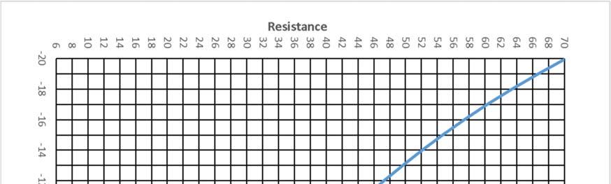
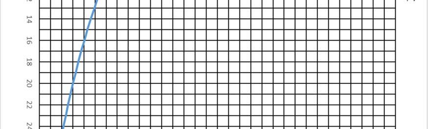
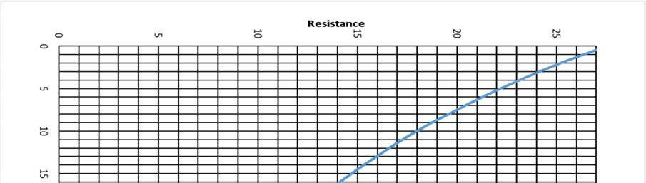
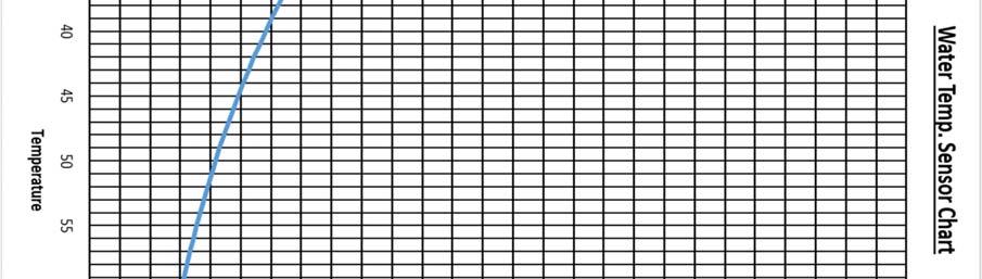
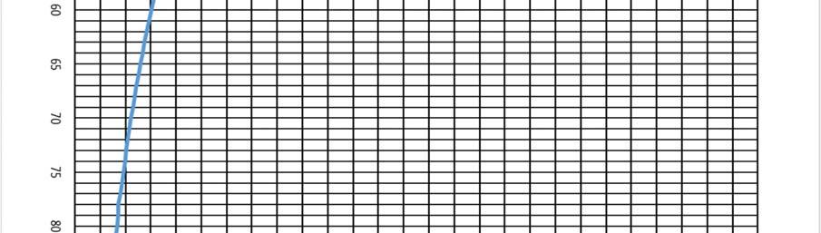
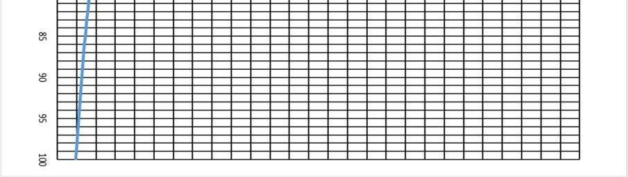
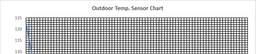
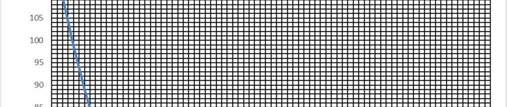
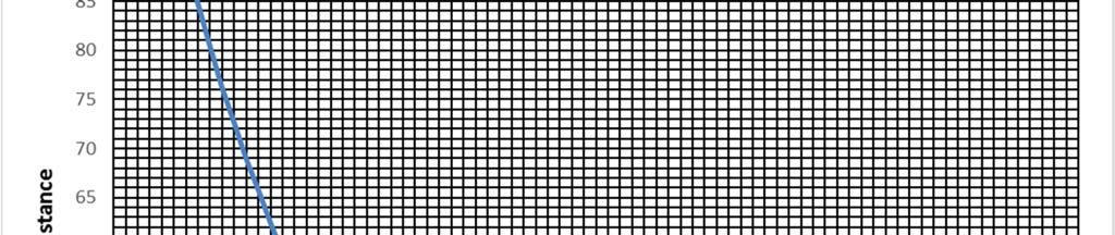
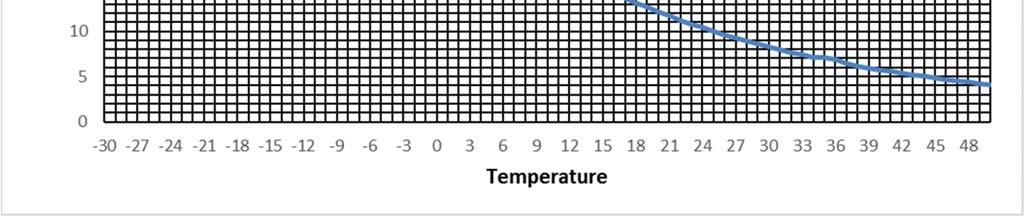
27 Service and Maintenance: A) Maintenance: At the beginning of each season, the air handler should be serviced by a qualified installer or service technician. Filter: The iflow series air handlers are provided with a disposable filter media. This filter should be inspected and replaced as required. Coils: the heating and air conditioning coils should not require regular maintenance IF a regular filter maintenance schedule is followed. In the event the filter is damaged or plugged and dust has fouled the coil, replace the filter and carefully vacuum the heating and or A/C coil. Circulator: The circulating pump is water lubricated and should not require no regular maintenance. The system control has a pump exercise function during prolonged periods of no heat to avoid seizing. B) Checking temperature sensors: 1. Remove cables from temperature sensor 2. Check the sensor resistance and compare the actual values with the curve on the chart. 3. Replace sensor is case of severe deviation 27


28 28
29 29


30 30

31 C) Wiring Diagram: 31
32 Field Installation Wiring Diagram 32

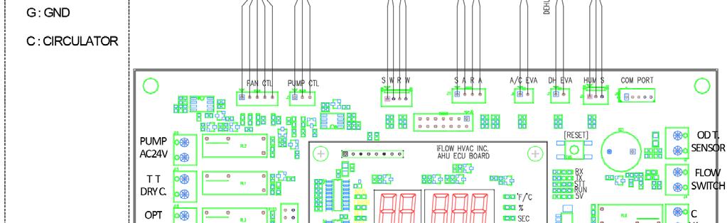
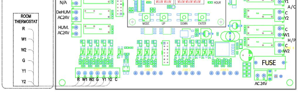
33 Control Board 33
34 D) Ladder Diagram 34
35 Troubleshooting A) Fault codes and Explanations: Segment Code Description Cause Resolution 001 Supply Air T. Sensor 002 Return Air T. Sensor Check sensor reading against corresponding temperature sensor chart. If out of range, replace sensor. 003 Supply Water T. Sensor Sensor 004 Return Water T. Sensor 005 A/C Evap. T. Sensor Sensor has no continuity. Sensor is out of measuring range. Faulty sensor 006 D.H. Evap. T Sensor 007 Outdoor T. Sensor 008 Humidity Sensor 020 H/ex. Freeze protection Ambient temperature below 36 F Unit will automatically run circulator until temperature is increased. Heat Exchanger 021 H/ex Overheating water temperature delta t below 3 F Ensure proper CFM, GPM. Make sure no restriction of water flow and airflow. Check sensor. Replace if necessary. Check filter. Check pump operation. A/C Evaporator 030 A/C Evap. Freeze protection 031 A/C Evap. Overheating Evaporator temperature below 37 F Air temperature delta t below 5 F check airflow. Check refrigerant level. Check proper A/C operation. Excessive cfm. Ensure proper A/C operation D.H. Evaporator 040 D.H. Evap. Freeze protection 041 D.H. Evap. Overheat Evaporator temperature below 37 F Air temperature delta t below 5 F 35
36 Water Flow 060 Abnormal Pump Operation Improper pump size. Improper piping. Pump failure. Air in circulator. Check proper voltage and connection to circulator. Ensure all causes are absent. If so, replace circulator. 070 Incorrect wiring Incorrect thermostat/control wiring Ensure all connections and tight and secure. 080 Over Cooling Return air temperature below 60.8 F during cooling mode Safety 081 Over Heating 082 Room Temp. High Return air temperature above 83 F during heating mode Return air temperature above 83 F before a call for heating Run blower fan until temperature returns to normal operating conditions. 083 Room Temp. Low Return air temperature below 60.8 F before a call for cooling 36
37 B) Problem and Solutions Insufficient or no heat: Filter or coil may be dirty. Refer to maintenance section for filter replacement and coil cleaning. Air trapped in heating loop. Purge system. Inlet and outlet connections to air handler are backwards. Reverse connections. Supply temperature is set too low. Check water temperature. There is a restriction in the heating loop. Remove restriction. Check valve may be stuck. Valves may be too restrictive or left partially closed after purging. Pump does not run: Close the isolation valve on the return leg and open the drain port so that water flows through the pump; this may free the pump. The circulator may allow you to remove the front screw on plate and rotate the shaft one turn with a slotted screwdriver. If either method fails to free the pump, removal for cleaning or replacement is necessary. The pump exercise function will help prevent pump seizing. Pump is noisy at start up: Air is present in the loop. If noise has not diminished after 1 minute, purge air in accordance with start up procedure. Fan runs for cooling but not for heating: Check thermostat connections or thermostat. Heating during standby mode: Probable cause is thermal syphoning. See check valve description for details. Repair or replace check valve. Freeze Protection: This feature is initiated by extremely low air temperatures and is detected by the ambient air sensor. Water Coil freeze protection: This feature is initiated by extremely low air temperatures crossing over the freeze protection sensor located above the hydronic heating coil. Cooling Lockout: This feature is initiated after three freeze protection cycles occur within a single cooling cycle, or if three freeze cycles occur when a cooling cycle is not in progress. A freeze protection cycle is when the air handler A/C coil freeze sensor is triggered by unacceptably low discharge air temperature. 37
38 C) Parts List No Description Part # Model Remark A iflh Heat Exchanger A iflh A iflh CW iflh DC CW 5 Blower Assembly CW iflh DC CW CW iflh DC CW B iflh Blower Assembly Bracket B iflh B iflh Blower Motor A iflh 14, A iflh B iflh 14, TR4803B Motor Bracket B IFLH TR6884B 15 Main CTL Board 30CTL01H 16 Display Setting Interface 30SIF01A 17 Circulator CTL Board 30PCTL1A 18 Circulator CTL Relay 30PRLY1A 19 Fuse 30LF2A1B 20 Air Supply Temp. Sensor 30ATS01B 21 Air Return Temp. Sensor 30ATR01B 22 Air Sensor Cable Harness 30ATH00A 23 Water Supply Temp. Sensor 30WTS01B 24 Water Return Temp. Sensor 30WTR01B 25 Water Sensor Harness 30WTH00A 26 A/C Eva. Temp. Sensor 30ETS01B 27 A/C Eva. T. Sensor Harness 30ETS00A 28 D.H. Eva. Temp. Sensor 30ETS01B 29 D.H. Eva. T. Sensor Harness 30ETS00A 30 Humidity Sensor 30HUS01A 31 Transformer B AC120V 20VA 32 Transformer B AC120V 40VA 33 Chork Transformer A 1 H 38
 60G0034S AC120V 60Hz 40 Outdoor T.")
39 No Description Part # Model Remark 34 Terminal 400T001B 35 Motor Power Cable 50121EON 16AWG 36 Motor CTL Cable 50MCTL1A 37 Pump CTL Cable 50PCTL1A 38 Circulator 60G1558A AC120V 60Hz 39 ¾ Union (Sweat) 60G0034S AC120V 60Hz 40 Outdoor T. Sensor Kit 30OTS01A 41 Stand 00STD01B 39
40 40
41 41
42 42
43 43
44 44
45 45
46 46
47 Warranty and Contact Information CHANGE TERM OF WARRANTY TO YOURS 1. Terms of Standard Warranty: All iflow air handler parts are warranted are to be free from defect in materials or faulty workmanship for a 36 month period from the date of original installation subject to the Conditions of Warranty set out below. When the original date of installation cannot be determined, the warranty will be deemed to begin six months after the date of manufacture. Replacement parts will only carry the unexpired portion of the warranty. 2. Warranty Procedure: Warranty parts shall be replaced by a qualified local contractor or dealer and will require the following information: Model number, serial number, date of installation and an accurate description of the problem. Contractor or dealer will contact a local iflow distributor for replacement parts. 3. Conditions of Warranty: iflow assumes no costs for warranty service or costs associated with the replacement of parts. This warranty does not include labor, including diagnostic labor nor any freight associated with the repair service, or sales tax that might be incurred by the purchaser under this warranty. This warranty does not cover defects caused by improper installation, modifications, alterations, abuse or accident to, or misuse of the product or its operation in a manner contrary to the instructions included with this unit at the time of shipment, or failure to perform maintenance as detailed in aforementioned instructions. This warranty will not cover normal maintenance, equipment that has been moved from its original installation location, operated beyond rated capacity and at voltages other than the rate specified in the nameplate, acts of god such as floods, winds, fires and lightning, exposed to corrosive elements such as salt, chlorine, fluorine or other damaging chemicals. This warranty will not cover part deficiencies due to lime or scale deposits. This warranty will not apply to damage or defect resulting from operation with system components other than those specified in the installation instructions, which are not authorized in writing by iflow manufacturing. 4. Limitations of Warranty: iflow manufacturing makes no express warranties other than the warranties set out above. All implied warranties including the implied warranties of merchantability and fitness for a particular purpose are excluded to the extent legally permissible, or are limited to a period of ONE year. Should such exclusion or limitation of warranty be unenforceable, such implied warranties are in any event limited to the duration of the express warranty, set forth above. Liability for incidental, punitive and/or consequential damages, whether arising out of breach warranty, breach of contract, negligence or otherwise, is excluded. Contact Info /
Total Comfort TC Series Air Handler
 INSTALLATION & OPERATING INSTRUCTIONS Total Comfort TC Series Air Handler READ AND UNDERSTAND THESE INSTRUCTIONS BEFORE OPERATING YOUR SUMMERAIRE TC SERIES AIR HANDLER THIS UNIT MUST BE INSTALLED AND SERVICED
Installation Manual NPE-180A/240A WARNING. Add-on Controller Installation Kit
 Installation Manual Add-on Controller Installation Kit NPE-180A/240A This device is designed to work with NPE-180A/240A models ONLY. WARNING All Installations should be done only by a qualified expert
Installation Manual WARNING. Add-on Controller Installation Kit NPE-180A/210A/240A
 Installation Manual Add-on Controller Installation Kit NPE-180A/210A/240A This device is designed to work with NPE-180A/210A/240A water heaters ONLY. WARNING All Installations should be done only by a
INSTALLATION INSTRUCTIONS
 INSTALLATION INSTRUCTIONS FOR AQUECOIL HYDRONIC HEATING UNITS GENERAL INFORMATION The AQUECOIL Hydronic Heating Unit is offered in many different capacities and physical configurations in order to match
WMWLB / WMWFM / WTWLB / WTWFM Series Hydronic Heating Unit
 January 2008 WMWLB / WMWFM / WTWLB / WTWFM Series Hydronic Heating Unit Installation Operation Maintenance The units are designed for permanent up flow, counter flow, or horizontal left or right airflow
CROWN. Boiler Co. Santa-Fe Series. Hydronic Air Handlers INSTALLATION, OPERATION & MAINTENANCE INSTRUCTIONS
 CROWN Boiler Co Santa-Fe Series Hydronic Air Handlers INSTALLATION, OPERATION & MAINTENANCE INSTRUCTIONS These instructions must be affixed on or adjacent to the air handler Models: SAC049A20 SAC059A25
Installation Instructions
 P700U -21NHP Base Non -Programmable Thermostats Installation Instructions Designed and Assembled in the USA. US patents: US20060165149 A1, USD578026 SI, US6205041 B1 A14005 Base Non---Programmable Thermostat
CAH SERIES INSTALLATION & MAINTENANCE MODELS CAH CAH
 CAH SERIES INSTALLATION & MAINTENANCE MODELS CAH 33-44-50 CAH 49-54-70 CAH VARIABLE SPEED AIR HANDLERS DIMENSIONS... 3 TECHNICAL SPECS... 4 INSTALLATION DON TS... 5 INSTALLATION DO S... 6 FREEZE STAT REQUIRED
Installation Instructions
 45 Cowansview Road Phone: 855-658-4330 www.ecologix.ca Cambridge, Ontario, N1R 7L2 Fax: 855-658-9384 info@ecologix.ca Installation Instructions Reliance Home Comfort ECRW Series Air Handler Very low profile
Technical Data Manual Model Nos. and pricing: see Price List
 Technical Data Manual Model Nos. and pricing: see Price List Viessmann AirflowPLUS AH2A series Hydronic forced air handler Viessmann AirflowPLUS Product may not be exactly as shown Viessmann AirflowPLUS
Safety, Installation, and Operation Manual
 Automatic Steam Humidifier Control Safety, Installation, and Operation Manual READ COMPLETE INSTALLATION INSTRUCTIONS BEFORE STARTING. WARNING This product must be installed by a qualified heating and
OWNER S MANUAL. Vintage Classic HEAT COOL models. Proudly Made in the USA
 OWNER S MANUAL Vintage Classic HEAT COOL models Proudly Made in the USA support@aquacomfort.com www.aquacomfort.com/service-and-support 888-475-7443 Manufacturing High Quality, High Efficiency Heat Pump
SuperStor Ultra Stainless Steel Storage Tank
 SuperStor Ultra Stainless Steel Storage Tank INSTALLATION START-UP MAINTENANCE PARTS Storage Tank Models SSU-30CB / SSU-45CB SSU-60CB / SSU-80CB / SSU-119CB For Residential and Commercial Use This manual
Model 1750A/ 1770A Dehumidifier Installation Instructions
 Model 1750A/ 1770A Dehumidifier Installation Instructions Safety Instructions WARNING 1. Improper installation may cause property damage or injury. Installation, service, and maintenance must be performed
OPERATION & INSTALLATION MANUAL
 OPERATION & INSTALLATION MANUAL Model: SIO 14 & SIO 18 Electric Tankless Hot Water Generators Table of Contents SAFETY INFORMATION... 1 INTRODUCTION... 2 Unit Operation:... 2 Unit Freezing:... 3 Maintenance:...
SPA BLOWER OWNER'S MANUAL XXXX, XXXX, XXXX, XXXX, XXXX, XXXX fax
 SPA BLOWER OWNER'S MANUAL 80015-XXXX, 80016-XXXX, 80017-XXXX, 80018-XXXX, 80019-XXXX, 80020-XXXX fax 888.610.3839 2015 323300-015 6/15 THIS PAGE INTENTIONALLY LEFT BLANK. 2 Operating Instructions and Parts
Steam Humidifier Fan Pack Installation & Maintenance Instructions
 850 Steam Humidifier Fan Pack 5658 Fan Pack Service Part Steam Humidifier Fan Pack Installation & Maintenance Instructions TABLE OF CONTENTS Safety Cautions...2 Materials List...3 Operation...3 Specifications
INSTALLATION & OPERATION GUIDE
 INSTALLATION & OPERATION GUIDE VERT-I-PAK A-SERIES SINGLE PACKAGE VERTICAL AIR CONDITIONING SYSTEM (05-08) 24,000 BTU/h Table of Contents Your Safety and the safety of others... 3 Installation Recommendations...
Installation, Operation & Service Manual
 Installation, Operation & Service Manual WARNING Improper installation, adjustment, alteration, service or maintenance can result in death, injury or property damage. Read the Installation, Operation and
ECAH SERIES ECM AIR HANDLER
 ECAH SERIES ECM AIR HANDLER ECAH40 OPERATING MANUAL TABLE OF CONTENTS 1 GETTING STARTED... 3 2 ELECTRICAL CONNECTIONS... 3 3 DIMENSIONAL DATA... 4 4 PLUMBING... 5 4.1 OPEN SYSTEM... 5 4.2 CLOSED SYSTEM...
Packaged Gas/Electric Units. Owner s Guide to Operating and Maintaining Your Gas/Electric Unit
 Packaged Gas/Electric Units Owner s Guide to Operating and Maintaining Your Gas/Electric Unit ELECTRICAL SHOCK HAZARD. FIRE OR EXPLOSION HAZARD Disconnect power at fuse box or service panel before performing
Safety & Installation Instructions
 Model 6203 & 6202 Zoned Comfort Control Safety & Installation Instructions READ AND SAVE THESE INSTRUCTIONS 61001213A 6202-6203 Zoned Comfort Control Install.indd 1 TABLE OF CONTENTS SAFETY INSTRUCTIONS..........................................
7-Day. Digital Thermostat. residential. & 2-cool
 Digital Thermostat residential THERMOSTAT T1100FS 7-Day PROGRAMMABLE up to 2-heat & 2-cool PUMP Control up to 2 Heat & 2 Cool Stages 7-Day Programmable 4 Settings/Day Auto Changeover 5 minute Built-In
USERS INFORMATION MANUAL
 MODULAR DX OR CHILLED WATER COOLING WITH ELECTRIC OR HOT WATER HEATING MODELS: US, UM SERIES USERS INFORMATION MANUAL For Installation In: 1. Modular Homes & Buildings 2. Residential Homes LIST OF SECTIONS
SEISCO SUPERCHARGER EXTENDER/BOOSTER INSTALLATION GUIDE & OWNERS MANUAL
 SEISCO SUPERCHARGER EXTENDER/BOOSTER INSTALLATION GUIDE & OWNERS MANUAL This manual is provided as a guide to installation. All installations must comply with any and all local and national electrical
ENGINEERING SPECIFICATIONS
 ENGINEERING SPECIFICATIONS RH-24-HAC-P-1L-C-SDE*F Horizontal Single Stage R410a Model Size 24 Reversing (Heating AND Cooling) 208/230-1-60VAC Liquid to Air Geothermal Heat Pumps Maritime Geothermal Ltd.
Advanced Installation and Configuration Instructions
 TP-WEM01-A Performance Series AC/HP Wi- Fi Thermostat Carrier Côr Thermostat Advanced Installation and Configuration Instructions Table of contents How to Use This Document... 3 Wiring Diagrams... 4 Installations
Safety & Installation Instructions
 Model 6303 & 6302 Zoned Comfort Control Safety & Installation Instructions READ AND SAVE THESE INSTRUCTIONS 61001212A 6302-6303 Zoned Comfort Control Install.indd 1 TABLE OF CONTENTS SAFETY INSTRUCTIONS..........................................
ENGINEERING SPECIFICATIONS
 ENGINEERING SPECIFICATIONS RH-12-HAC-P-1L-C-SDE*F Horizontal Single Stage R410a Model Size 12 Reversing (Heating AND Cooling) 208/230-1-60VAC Liquid to Air Geothermal Heat Pumps Maritime Geothermal Ltd.
BESF Box Ventilator. Installation & Operating Manual USA CAN READ AND SAVE THESE INSTRUCTIONS
 Installation & Operating Manual 3001806 03.02 USA CAN BESF Box Ventilator READ AND SAVE THESE INSTRUCTIONS 1200 Northmeadow Parkway, STE 180 Roswell, GA 30076 (770) 587-3238 (800) 255-2923 Fax (770) 587-4731
Your safety and the safety of others are very important.
 VARIABLE SPEED ELECTRIC FURNACE INSTALLATION INSTRUCTIONS VARIABLE SPEED ELECTRIC FURNACE SAFETY...1 INSTALLATION REQUIREMENTS...2 Tools and Parts...2 Location Requirements...2 Installation Configurations...3
Total Comfort TC Series Air Handler
 INSTALLATION & OPERATING INSTRUCTIONS Total Comfort TC Series Air Handler NOTICE TO HOMEOWNER THIS PRODUCT MUST BE INSTALLED AND SERVICED BY A QUALIFIED INSTALLER AND WHERE REQUIRED BY LAW, A LICENSED
OWNER S MANUAL. Vintage Signature Series models: AC750, AC1050, AC1100, AC1250, AC1500, AC1750. Proudly Made in the USA.
 OWNER S MANUAL Vintage Signature Series models: AC750, AC1050, AC1100, AC1250, AC1500, AC1750 Proudly Made in the USA support@aquacomfort.com 888-475-7443 Manufacturing High Quality, High Efficiency Heat
Model 1870F Dehumidifier Installation and Operating Manual
 Model 1870F Dehumidifier Installation and Operating Manual ON/OFF button used to turn dehumidifier on and off Up/Down buttons used to change humidity setting Dehumidifer Control Outlet MODE button used
OPERATING & MAINTENANCE MANUAL HORIZONTAL WATER SOURCE HEAT PUMP. World class comfort.
 OPERATING & MAINTENANCE MANUAL HORIZONTAL WATER SOURCE HEAT PUMP World class comfort. welcome Congratulations on your selection of Ice Air Water Source Heat Pumps (WSHPs) for your comfort conditioning
B Series Multi-Position & Hydronic Air Handlers Electric or Hot Water Heat, with available Variable-Speed High Efficiency ECM Motor
 IM-BAH-0662402-10 May 2013 Installation Instructions B Series Multi-Position & Hydronic Air Handlers Electric or Hot Water Heat, with available Variable-Speed High Efficiency ECM Motor Table of Contents
Vertical Concealed Fan Coil. FCVC Series MANUAL INSTALLATION, OPERATION, & MAINTENANCE
 MANUAL INSTALLATION, OPERATION, & MAINTENANCE Vertical Concealed Fan Coil FCVC Series v100 Issue Date: 12/21/15 2015 Price Industries Limited. All rights reserved. TABLE OF CONTENTS Product Overview Safety
OPERATION INSTRUCTIONS DEMAND DEFROST CONTROL BOARD MODEL FOR USE WITH MODELS: AFFINITY, ECHELON, ACCLIMATE HEAT PUMP SERIES
 OPERATION INSTRUCTIONS DEMAND DEFROST CONTROL BOARD MODEL 500644 FOR USE WITH MODELS: AFFINITY, ECHELON, ACCLIMATE HEAT PUMP SERIES A047-001 FIGURE 1: Demand Defrost Control Module ANTI-SHORT CYCLE DELAY
Installation Instructions
 Installation Instructions Make Up Air Unit with high efficiency EC motor 45 Cowansview Rd. Cambridge, Ontario N1R 7L2 Phone: 888-781-8151 Fax: 888-670-2544 info@vortexsource.com www.vortexsource.com MUA-1402
The Premium Quality Fan Coil Units for Vertical, Horizontal (Left or Right) Application with Direct Expansion, Hydronic or Electric Heat
 Application with Direct Expansion, Hydronic or Electric Heat") Producing Quality Heating & Cooling Equipment For Over 50 Years DUW/DUX SERIES 1.5 THROUGH 5 TON VERTICAL OR HORIZONTAL FAN COIL UNITS The Premium Quality Fan Coil Units for Vertical, Horizontal (Left
Producing Quality Heating & Cooling Equipment For Over 50 Years DUW/DUX SERIES 1.5 THROUGH 5 TON VERTICAL OR HORIZONTAL FAN COIL UNITS The Premium Quality Fan Coil Units for Vertical, Horizontal (Left
TH146-N-2H1C. 1. Introduction. 2. Installation. 1.1 Applications. 2.1 Control Module (CT280-2H1C) 1.2 Supplied Parts. 1.
 1.2 Supplied Parts. 1.") TH146-N-2H1C Installation Guide Non-programmable H/C Controller Removable Connector * Removable Connector * TH146 User Console CT280-2H1C Control Module AC144-03 Outdoor Temperature Sensor * To remove
TH146-N-2H1C Installation Guide Non-programmable H/C Controller Removable Connector * Removable Connector * TH146 User Console CT280-2H1C Control Module AC144-03 Outdoor Temperature Sensor * To remove
INDIRECT FIRED WATER HEATERS
 H E A T T R A N S F E R P R O D U C T S INDIRECT FIRED WATER HEATERS RESIDENTIAL COMMERCIAL Heat Transfer Products, Inc., reserves the right to make product changes or updates without notice. Heat Transfer
Emerson Inspire 1HDEZ Installation Instructions. Thermostat/Interface Equipment Control TROUBLESHOOTING
 Emerson Inspire 1HDEZ-1521 Installation Instructions Thermostat/Interface Equipment Control TROUBLESHOOTING FAILURE TO READ AND FOLLOW ALL INSTRUCTIONS CAREFULLY BEFORE INSTALLING OR OPERATING THIS CONTROL
TECHNICAL GUIDE DESCRIPTION SPLIT-SYSTEM AIR-COOLED CONDENSING UNITS MODELS: HF-07 FEATURES B-0703
 TECHNICAL GUIDE SPLIT-SYSTEM AIR-COOLED CONDENSING UNITS MODELS: HF-07 DESCRIPTION These Sunline 2000 units are completely assembled, piped and wired at the factory to provide one-piece shipment and rigging.
Model 1850F Dehumidifier Installation and Operating Manual
 Model 1850F Dehumidifier Installation and Operating Manual ON/OFF button used to turn dehumidifier on and off Up/Down buttons used to change humidity setting Dehumidifer Control Outlet MODE button used
OWNER S MANUAL. Models: AC110, AC125, AC150 made from 2003 through Proudly Made in the USA
 OWNER S MANUAL Models: AC110, AC125, AC150 made from 2003 through 2010 Proudly Made in the USA support@aquacomfort.com www.aquacomfort.com/service-and-support/ (888) 475-7443 Manufacturing High Quality,
PCAH SERIES AIR HANDLER
 PCAH SERIES AIR HANDLER PCAH2/PCAH3/PCAH4 OPERATING MANUAL 1 2 3 4 5 6 7 8 9 10 TABLE OF CONTENTS GETTING STARTED... 3 ELECTRICAL CONNECTIONS... 3 2.1 POWER CONNECTIONS... 3 2.1.1 PCAH2/PCAH3... 3 2.1.2
THE HEATING BOX. Training Manual. Model KD-HBO100 & KD-HBC100. * KD-HB100 (Open-Loop System) * KD-HBC100 (Close-Loop System)
 * KD-HBC100 (Close-Loop System)") THE HEATING BOX Training Manual Model KD-HBO100 & KD-HBC100 * KD-HB100 (Open-Loop System) * KD-HBC100 (Close-Loop System) Automatic Hot Water Management System A Combination System for Domestic Water and
THE HEATING BOX Training Manual Model KD-HBO100 & KD-HBC100 * KD-HB100 (Open-Loop System) * KD-HBC100 (Close-Loop System) Automatic Hot Water Management System A Combination System for Domestic Water and
Use & Care Manual. Electric Tankless Water Heaters. With Installation Instructions for the Installer AP15447 (10/10)
") Use & Care Manual With Installation Instructions for the Installer Electric Tankless Water Heaters The purpose of this manual is twofold: one, to provide the installer with the basic directions and recommendations
Use & Care Manual With Installation Instructions for the Installer Electric Tankless Water Heaters The purpose of this manual is twofold: one, to provide the installer with the basic directions and recommendations
WIRING DIAGRAMS R410A MODELS PAC 2OAC/2OACH CAC OWC PWC
 WIRING DIAGRAMS R410A MODELS 2OAC/2OACH PAC CAC PWC OWC WIRING 02172017 TABLE OF CONTENTS PAGE 2OACH Deluxe Portable Air-cooled Heat Pump Electronic Controller... 2-3 Piping Schematic... 4 Single Phase
Installation Instructions
 EZXCAB Sizes 016 and 020 High Efficiency Air Filtration System Installation Instructions JAN High Efficiency Air Filtration System Fig. 1 - EZXCAB C04001 NOTE: Read the entire instruction manual before
Model R060 Installation - Operation Manual
 Residential Heat Pump Water Heaters Model R060 Installation - Operation Manual Important Note Read this entire manual before beginning installation Manufactured By: 6670-A Corners Industrial Court Norcross,
INSTALLATION INSTRUCTIONS and OPERATING MANUAL. *Aquastat is a registered trademark of Honeywell International, Inc.
 MODEL 3200-Plus Temp Limit / LWCO Control with Thermal Targeting for Water Boilers 120 VAC Input / 24 VAC Burner Circuit PATENT. 8,931,708; 8,844,834; 7,891,572; others pending INSTALLATION INSTRUCTIONS
AG Series Electric Heaters
 AG Series Electric Heaters Auxiliary Electric Heat Installation, Operation & Maintenance Instructions 97B0005N04 Table of Contents Overview 3 Vertical Upflow or Downflow Installation - Internal 3 Vertical
Heat Transfer Products, Inc. 120 Braley Road East Freetown, MA The first totally integrated multiple boiler management control.
 Heat Transfer Products, Inc. 120 Braley Road East Freetown, MA 02717 The first totally integrated multiple boiler management control. USING THIS MANUAL USING THIS MANUAL A. INSTALLATION SEQUENCE Follow
Installation & Operation Manual Models: TSU
 TSU-I-O Rev A Installation & Operation Manual Models: TSU 150-940 CAUTION: This appliance is not intended for potable water. This manual must only be used by a qualified heating installer / service technician.
OPERATION & INSTALLATION MANUAL IR-30, IR-234, IR-245, IR-260, IR-288, IR-14K220, IR-18K220. Electric Tankless Hot Water Heater
 OPERATION & INSTALLATION MANUAL IR-30, IR-234, IR-245, IR-260, IR-288, IR-14K220, IR-18K220 Electric Tankless Hot Water Heater Table of Contents SAFETY INFORMATION... 1 INTRODUCTION... 2 Unit Operation...
MX Series Indoor Modular Blowers Electric Heat, Hot Water Heat, or No Heat
 SG-MAH-08 April 2016 MX Series Indoor Modular Blowers Electric Heat, Hot Heat, or No Heat Specification Guide Contents...Pa Page Standard Features... 2 Physical Data... 2 Blower Performance... 3 Nomenclature...
Installation and Service Manual. In-Floor Warming Module external desuperheater for 3rd party air source heat pumps
 Installation and Service Manual IFM-Series In-Floor Warming Module Model Size 48 In-Floor Warming Module external desuperheater for 3rd party air source heat pumps Maritime Geothermal Ltd. P.O. Box 2555
ThermoSaver TM Hot Gas Defrost System
 PRODUCT DATA, APPLICATION & INSTALLATION GUIDE Supplement to Condensing Unit Installation and Maintenance Manual Bulletin B40-THERM-PDI-14 1069132 ThermoSaver TM Hot Gas Defrost System For use on select
Installation, Operation and Service Manual
 Installation, Operation and Service Manual Conforto Electric Furnace KHE 10 TO 27kW INSTALLATIONS MUST MEET ALL LOCAL AND FEDERAL CODES THAT MAY DIFFER FROM THIS MANUAL Please read the manual in its entirety
WKS 4000 SERIES (USA only) --INSTALLATION INSTRUCTIONS--
 --INSTALLATION INSTRUCTIONS--") 8610 Production Avenue San Diego, California 92121 (858) 566-7465 Fax (858) 566-1943 WKS 4000 SERIES (USA only) --INSTALLATION INSTRUCTIONS-- Thank you for choosing a BREEZAIRE cooling unit. We believe
8610 Production Avenue San Diego, California 92121 (858) 566-7465 Fax (858) 566-1943 WKS 4000 SERIES (USA only) --INSTALLATION INSTRUCTIONS-- Thank you for choosing a BREEZAIRE cooling unit. We believe
WMHP Series R410a Heat Pump INSTALLATION INSTRUCTIONS
 WMHP Series R410a Heat Pump INSTALLATION INSTRUCTIONS **WARNING TO INSTALLER, SERVICE PERSONNEL AND OWNER** Altering the product or replacing parts with non authorized factory parts voids all warranty
Tranquility Digital Quick Start Guide
 Tranquility Digital Quick Start Guide 97B0107N01 Residential Packaged and Split DIGITAL Geothermal Heat Pumps With igate and vflow Technology B Step Title Page 1 Thermostat Confi guration 3 Staging 3 Auxiliary
Quest Power Electric Heat EHS 31 Pro
 Quest DRY Power 150 Electric Heat EHS 31 Pro Read and Save These Instructions The Power Electric Heat EHS 31 Pro portable, heavy duty electric heater features a built-in 50-amp twist lock receptacle designed
MACH N-407 Heat Pump Air-Cooled Chiller
 MACH060-01-N-407 Heat Pump Air-Cooled Chiller Heat Pump Air-Cooled Chillers for Global Residential and Light Commercial Microclimates MACH NOMENCLATURE BREAKDOWN MACH-060-01 - N - 407 Refrigerant Type
OWNER'S MANUAL T0140. Contents Page #
 Digital Thermostat residential THERMOSTAT T0140 NON- PROGRAMMABLE up to 2-heat & 1-cool PUMP Stages: 2-Heat, 1-Cool Battery or System Powered Auxiliary Heat Indicator Fahrenheit or Celsius Bi-Color LED
BasicTroubleshooting Information and Guidelines
 BasicTroubleshooting Information and Guidelines BasicTroubleshooting Information and Guidelines Information and Guidelines May 2017 BasicTroubleshooting PRIOR TO CONTACTING CLIMATEMASTER TECHNICAL SUPPORT,
Installation and Operations Manual
 Installation and Operations Manual H-IM-LLC February 2018 Part No. 25092501 Replaces H-IM-LLC (01/2014) Lead Lag Control System Table of Contents General Safety Information 2 Inspection 2 Warranty Statement
Surna 25-Ton Chiller Operating & Maintenance Manual
 www.surna.com 303.993.5271 Surna 25-Ton Chiller Operating & Maintenance Manual Models: 300F3-3. 300F4-3, 300FW-3 Revised: July 2015 Table of Contents Warranty Information 4 Limited Warranty 4 Limitation
Multiple Boilers Electro TS Series Application EB-C-STG5
 Multiple Boilers Electro TS Series Application EB-C-STG5 Drawings: BC025 BX404 BH504 XX017 Information All Electro-Boilers, except Mini-Boiler, have the same control board (EB5623**). The plug-in control
B Series Multi-Position & Hydronic Air Handlers Electric or Hot Water Heat, with available Variable-Speed High Efficiency ECM Motor
 IM-BAH-0662402-18 August 2018 Installation Instructions B Series Multi-Position & Hydronic Air Handlers Electric or Hot Water Heat, with available Variable-Speed High Efficiency ECM Motor TABLE OF CONTENTS
VENSTAR T1070 FAN COIL THERMOSTAT PROGRAMMABLE 2 OR 4 PIPE SYSTEMS OWNER S MANUAL AND INSTALLATION INSTRUCTIONS
 VENSTAR FAN COIL THERMOSTAT FAN COIL THERMOSTAT T1070 NON- PROGRAMMABLE 2 OR 4 PIPE SYSTEMS Remote sensor ready 3 speed fan control Self-prompting adjustment Auto 2-pipe changeover when used with ACC-SENFC
Residential Duct Mount Builder s Box Media Air Cleaner
 INSTALLATION, OPERATION, AND MAINTENANCE INSTRUCTIONS Residential Duct Mount Builder s Box Media Air Cleaner Part Numbers: P102-BB14A, P102-BB20 IMPORTANT: Read entire instructions before installing the
Standard and CELDEK Evaporative Cooler Modules Installation, Operation, and Maintenance Manual
 Standard and CELDEK Evaporative Cooler Modules Installation, Operation, and Maintenance Manual Standard Evaporative Cooler CELDEK Evaporative Cooler RECEIVING AND INSPECTION Upon receiving unit, check
Owner s Manual Phoenix FireBird
 4201 Lien Rd Madison, WI 53704 Owner s Manual Phoenix FireBird Installation, Operation and Service Instructions Important Instructions Read and Save These Instructions The FireBird portable, heavy duty
INSTALLATION & OPERATION MANUAL
 INSTALLATION & OPERATION MANUAL Model TME- * * Balance of model number is determined by customer specifi ed limits and Setbacks. AUTOMATIC SETBACK THERMOSTAT LIGHT SENSING OR CONTACT CLOSURE FOR LOW VOLTAGE
Standard and CELDEK Evaporative Cooler Modules Installation, Operation, and Maintenance Manual
 Standard and CELDEK Evaporative Cooler Modules Installation, Operation, and Maintenance Manual Standard Evaporative Cooler CELDEK Evaporative Cooler RECEIVING AND INSPECTION Upon receiving unit, check
MAC N-407 Air-Cooled Chiller
 MAC036-01-N-407 Air-Cooled Chiller Air-Cooled Chillers for Global Residential and Light Commercial MicroClimates MAC036 NOMENCLATURE BREAKDOWN MAC036-01 - N - 407 Refrigerant Type Air-Cooled Chiller 036=
Portable Air Conditioner, Dehumidifier,Heater and Fan utilizing Heat Pump Technology
 Portable Air Conditioner, Dehumidifier,Heater and Fan utilizing Heat Pump Technology OWNER'S MANUAL Model # KY-34 3046364 Please read owner s manual carefully before operating unit. TABLE OF CONTENTS INTRODUCTION...3
Quest Power Electric Heat EHS 62 Pro
 Quest DRY Power 150 Electric Heat EHS 62 Pro Read and Save These Instructions The Quest Power Electric Heat EHS 62 Pro portable, heavy duty electric heater features multiple power receptacles for connection
CWR265SZ 26 Bottle Built-in Wine Cooler Owner s Manual
 CWR265SZ 26 Bottle Built-in Wine Cooler Owner s Manual This owner s manual provides instructions on safe installation use, and troubleshooting assistance. Please read it carefully and save it for reference
JH Series Installation
 JH Series Installation Space Heating / Fresh Air Make-Up From the Manufacturers of Hi-Velocity Systems TM Includes: JH-15 JH-30 Module-JH-Series-Installation-Manual-010118 Installation JH fan coils by
VENSTAR T1075 FAN COIL THERMOSTAT 7 DAY PROGRAMMABLE 2 OR 4 PIPE SYSTEMS OWNER S MANUAL AND INSTALLATION INSTRUCTIONS
 VENSTAR FAN COIL THERMOSTAT FAN COIL THERMOSTAT T1075 7 DAY PROGRAMMABLE 2 OR 4 PIPE SYSTEMS 3 Occupied, 1 Unoccupied Override capable 3 speed fan control Auto 2-pipe changeover when used with accessory
ECCOTEMP. Point of Use Tankless Water Heaters EP-2.4 / EP-7.0. Installation and Operating Instruction Manual. Shop Online.
 ECCOTEMP Point of Use Tankless Water Heaters EP-2.4 / EP-7.0 Installation and Operating Instruction Manual Product Support Eccotemp.com/help-desk Shop Online Eccotemp.com/products Store Locator Eccotemp.com/locator
Model DEHXXCDA1070 & DEHXXCDA1095 Dehumidifier Installation Instructions
 Model DEHXXCDA1070 & DEHXXCDA1095 Dehumidifier Installation Instructions Safety CONSIDERATIONS Improper installation, adjustment, alteration, service, maintenance, or use can cause explosion, fire, electrical
INSTALLATION INSTRUCTIONS FMB/FMC SERIES MULTI-POSITION AIR HANDLER
 ASPEN MANUFACTURING 373 ATASCOCITA RD. HUMBLE, TX 77396 TEL (281) 441-6500 FAX (281) 441-6510 > INSTALLATION INSTRUCTIONS FMB/FMC SERIES MULTI-POSITION AIR HANDLER IMPORTANT: "The
Safety & Installation Instructions
 Premium Programmable Thermostat Safety & Installation Instructions Model 8570 READ AND SAVE THESE INSTRUCTIONS TABLE OF CONTENTS PAGE SPECIFICATIONS............................. 1 WIRE REQUIREMENTS.........................
Installation Instructions
 50ZPB, C, 50ZHB, C, PA3Z ---A, PH3Z ---A, PA4Z, PH4Z, PAJ4,PHJ4,WJA4,WJH4 SMALL PACKAGED PRODUCTS (SPP) Accessory Electric Heaters 5---20 kw For 14 SEER, R---410A Manufactured Home Installation Instructions
Non-Programmable Digital Thermostat
 OWNER'S MANUAL MODEL P474-0140 Non-Programmable Digital Thermostat HEAT PUMP THERMOSTAT 2 HEAT, 1 COOL emergency aux. heat normal energy save Fan On Fan Auto Millivolt Compatible Battery or System Powered
Safety and Installation Instructions Model 1700
 Dehumidifier Filter Access Humidity Control Inlet Filter Access Outlet Service Access Port Wiring Access Wire Routing Port Drain On/Off Switch Safety and Installation Instructions Model 1700 INSTALLER
EBAC MODEL CD425 ( ) INDUSTRIAL DEHUMIDIFIER OWNER S MANUAL
 INDUSTRIAL DEHUMIDIFIER OWNER S MANUAL") EBAC MODEL CD425 (1018110) INDUSTRIAL DEHUMIDIFIER OWNER S MANUAL Ebac Industrial Products, Inc. 700 Thimble Shoals Blvd, Suite 109 Newport News, VA. 23606-2575 Tel: (757) 873 6800 Fax: (757) 873 3632
EBAC MODEL CD425 (1018110) INDUSTRIAL DEHUMIDIFIER OWNER S MANUAL Ebac Industrial Products, Inc. 700 Thimble Shoals Blvd, Suite 109 Newport News, VA. 23606-2575 Tel: (757) 873 6800 Fax: (757) 873 3632
Owner s Manual. Digital Thermostat
 Model Air Conditioning & Heating Heat Pump 5+2 Day Programmable Digital Thermostat Control up to 2-Heat & 1-Cool Battery or System Powered Backlit Digital Display Auxiliary Heat Indicator Fahrenheit or
TMC. Installation and Operation Manual TMC. Temperature and Pressure Monitoring for Heating and Cooling Applications. Temperature Monitoring Control
 Installation and Operation Manual Temperature and Pressure Monitoring for Heating and Cooling Applications Temperature Monitoring Control VALVE OPEN ALARM System= 128 o F Alarm At= 130 o F RESET /BACK
INSTALLATION INSTRUCTIONS FMB/FMC SERIES MULTI-POSITION AIR HANDLER
 INSTALLATION INSTRUCTIONS FMB/FMC SERIES MULTI-POSITION AIR HANDLER IMPORTANT MASSAGE TO INSTALLER: "The United States Environmental Protection Agency ("EPA") has issued various regulations regarding the
Quest Dry 105, 155, and 205 Dual
 Quest Dry 105, 155, and 205 Dual Read and Save These Instructions This manual is provided to acquaint you with the dehumidifier so that installation, operation and maintenance can proceed successfully.
Service Manual ES50LVS / ES90LVS MULTI-SPEED AIR HANDLER. Ecosmartair 105 Haist Avenue, Unit 10 Vaughan, ON L4L 5V ecosmartair.
 ES50LVS / ES90LVS MULTI-SPEED AIR HANDLER Service Manual Ecosmartair 105 Haist Avenue, Unit 10 Vaughan, ON L4L 5V6 905-857-9755 ecosmartair.com P/N 14009A 1 P a g e Contents CONTROL ASSEMBLY LAYOUT...
be liable for any other loss or damage, whether direct, indirect, incidental or consequential.
 Integrated HydroStat 3200-Plus for Slant Fin Boilers Part No. 48-3200-03 and 48-3200-04 120 VAC Input / 24 VAC Burner Circuit PATENT S. 8.391,708; 7,891,572; 8,844,834; Others Pending INSTALLATION INSTRUCTIONS
Healthy Climate Whole-Home Dehumidifier. Nominal Capacity - 70 to 130 pints per day INDOOR AIR QUALITY HCWHD PRODUCT SPECIFICATIONS.
 PRODUCT SPECIFICATIONS INDOOR AIR QUALITY HCWHD Healthy Climate Whole-Home Dehumidifier Bulletin No. 210699 November 2017 Supersedes April 2017 MODEL NUMBER IDENTIFICATION Nominal Capacity - 70 to 130
Owner s Manual. Digital Thermostat. Non-Programmable
 Model Air Conditioning & Heating Non-Programmable Digital Thermostat 1-Heat & 1-Cool Gas/Electric Heat Pump Battery or System Powered Fahrenheit or Celsius Fully Electronic Owner s Manual Thank goodness