FORCE SERIES SWIMMING POOL HEAT PUMP INSTALLATION AND OPERATION MANUAL PLEASE READ THIS MANUAL CAREFULLY BEFORE INSTALLING OR OPERATING THE UNIT
|
|
|
- Jody Hart
- 5 years ago
- Views:
Transcription


1 FORCE SERIES SWIMMING POOL HEAT PUMP INSTALLATION AND OPERATION MANUAL PLEASE READ THIS MANUAL CAREFULLY BEFORE INSTALLING OR OPERATING THE UNIT 1


2 CHAPTER 1: Installation Chapter 1 deals with installation of your Evoheat pool heater and is predominately for use by your installer/ technician. Evo recommends however that owners make themselves familiar with this chapter. CHAPTER 2: Operation Chapter 2 covers operation of your Evoheat pool heater including basic and advanced operation modes and maintenance/ troubleshooting. Please take the time to read this manual thoroughly. Failure to do so can void customer warranty, cause possible damage to your heater, and may cause a loss of heater efficiency. 2 3
3 Table of Contents Table of Contents 1. General information Introduction Consumer and Safety Information Energy Saving Tips 4 2. Specifications Technical specifications of Force models Dimensions 6 CHAPTER 1 Installation 8 1. Air Flow 8 2. Water Flow 8 3. Electrical Connection 9 4. Heater Condition 9 3. General Installation Information Inspection Location Clearances Water Flow and Plumbing Setup Water Pump Connection 12 Installation Options Slave Mode Seperate Systems EVO JBox Drainage Electrical Connection Remote Controller Connection 15 CHAPTER 2 Operation 16 Display Explanation Controller Operation 16 Control Panel Explanation 16 Operation Instructions 17 a) On-off Operation 17 b) Mode Selection 18 d) Keyboard Lock and Unlock 19 e) Clock Setting 20 f) Timer On and Off Setting 21 g) Parameter Setting PCB I/O Ports Description Parameter 28 Parameter Table 28 Description of the Parameters 30 MAINTENANCE AND TROUBLESHOOTING Maintenance Troubleshooting 35 Troubleshooting Guide 36 Appendix Temp Sensor Probes 37 Appendix A Wiring Diagrams 38 Appendix B Technical Data 41 EVOHEAT Warranty 46 Warranty Registration
4 1. General information 2. Specifications 1.1 Introduction 2.1 Technical specifications of Force models This manual provides installation and operation instructions for EVOHEAT heat pumps. Read these installation and operation instructions carefully before proceeding with the installation and operation of your heater. Consult your EVOHEAT Distributor with any questions regarding this equipment. Installation and service must be performed by a qualified installer. The manufacturer will not be responsible for any damage to the unit or injury caused by improper installation, operation or maintenance. 1.2 Consumer and Safety Information a. Evo recommends 27 C as the optimum water temperature for swimming. b. The consumption of alcohol or drugs before or during spa or pool use can cause drowsiness which could lead to unconsciousness and subsequent risk of drowning. c. Immersion in water exceeding 38 C during pregnancy is not recommended. d. The water temperature should always be checked with an accurate thermometer before entering a spa or hot tub. e. Persons with a medical history of heart disease, diabetes, circulatory or blood pressure problems should consult their physician before using a hot tub or spa. f. Persons taking any medication or drugs which induce drowsiness (e.g., tranquilizers, antihistamines, or anticoagulants) should not use spas or hot tubs. g. Prolonged immersion in hot water can induce hyperthermia. 1.3 Energy Saving Tips It is important to note that a heat pump will not heat a pool as fast as a large gas pool heater. If the pool water is allowed to cool significantly, it may take several days to return to the desired swimming temperature. For weekend use, it is more economical to maintain the pool water temperature at or near your desired swimming temperature. If you do not plan to use your pool for a prolonged period, then you might choose to turn the heat pump completely off or decrease the temperature setting of the control several degrees to minimize energy consumption. MODEL Force5 Force9 Force14 Force18 Force22 Force26 Heat Output at max ambient deg water (kw) Heat Ouput at 24 deg air deg water (kw) Heat Ouput at 15 deg air deg water (kw) Cooling Output at 35 deg air deg water (kw) Power Supply 240/1/50 240/1/50 240/1/50 240/1/50 240/1/50 240/1/50 Power Input at 24 deg (kw) COP at 24 deg air Noise level d(b)a Normal/Maximum Running / / / / /27.2 Current Refrigerant (R407c/KG) 0.5kg 0.8kg 1.3kg 1.7kg 2.4kg 2.4kg Compressor type Rotary Rotary Rotary scroll scroll scroll pvc water connection(mm) Water flow rate(l/min) Shipping dimensions LxWxH (mm) 805x380x Unit dimensions LxWxH (mm) 810x350x x420x x420x x470x x470x x470x1240 Weight packed/unpacked(kg) 40/42 67/60 72/65 108/ / /147 FEATURES Titanium heat exchanger y y y y y y Touch screen intelligent y y y y y y controller Thermal expansion valve y y y y y y Galvanised powder coated n y y y y y corrosion resistant steel cabinet y n n n n n Corrosion-free PVC cabinet y n n n n n Air flow direction horizontal y y y y y y Automatic defrost system y y y y y y Heat or cool automatic y y y y y y function Compact design - small y y y y y y footprint Low noise fan blades y y y y y y 6 7
5 Use an accurate pool thermometer. A difference of 2 C, between 26 C and 28 C, will significantly increase energy consumption. b. Carefully monitor the water temperature of your pool in the summer time. You can reduce heat pump usage due to warmer air temperatures. c. When the pool is not to be used for long periods, turn off the heat pump. d. Where possible, shelter the pool from prevailing winds with well-trimmed hedges or other landscaping, cabanas, or fencing. e. Always use a high quality pool cover when practical. Besides providing a valuable water saving feature, a pool cover will dramatically reduce heat loss. See attached appendix for further information. unit Model:Force 5 unit Model:Force 18 mm a Water Outlet 50 mm Water Inlet Water outlet Water inlet Model:Force 22 / Force Model:Force 9 / Force Water inlet 50 Water Outlet Water Inlet Water outlet


6 CHAPTER 1 Installation Before installation it is very important to ensure 4 variables are carefully checked to allow the unit to operate correctly: 3. Electrical Connection Always use a qualified Electrician to perform any electrical work. Ensure the power cable and circuit breaker are of a suitable size for the heater being installed. Also check that there is adequate voltage and current available at the heater connection to run the unit. Voltage range should be volts for single phase, and volts for 3 phase units. Voltage ranges outside these parameters will cause heater damage and void your warranty. Correct phase connection is important with 3 phase heaters. SEE PAGE 10 FOR FURTHER INFORMATION 1. Adequate Air Flow 2. Correct water flow volume 3. Correct electrical connection & supply 4. Heater condition 4. Heater Condition Check the heater packaging upon delivery for any obvious signs of damage. Inform your supplier IMMEDIATELY if there is any evidence of rough handling. When the heater has been removed from the packaging check the refrigerant gauge on the front panel of the unit. The gauge should be showing a pressure of approx 1Mpa on the outside black band any less than this figure means there may be a leak in the refrigerant system and you should immediately contact your Evoheat Dealer. 1. Air Flow Installing the heater indoors or in an enclosed space will result in very poor performance and can in extreme cases damage the heater. Ensure the heater is installed in a well ventilated area with plenty of fresh air, a minimum gap between walls/fences etc of 600mm on the sides and 1500mm overhead clearance. Example of a unit with a refrigerant leak and zero pressure notify Evoheat Dealer. Important: Ensure that the cold air off the top of the heater does not recycle through the heater. SEE PAGE 8 FOR FURTHER INFORMATION 2. Water Flow It is CRITICAL that there is sufficient water flow to the unit. Incorrect water flow can cause a loss of efficiency and possible damage to the unit. Optimal water flow rates are listed in the Evoheat sales brochure and in this manual on page 5. It is imperative that water flow is kept as close as possible to these flow rates. Correct water flow not only offers optimal heater performance, but may also prevent possible damage to your heater. SEE PAGE 9 FOR FURTHER INFORMATION 3. General installation information 3.1 Inspection Inspect the packaging, the heater and other items after receipt for possible damage in transportation. Please contact your EVOHEAT dealer immediately should you suspect any damage has occurred during transportation. Install your EVOHEAT heat pump in accordance with the procedures in this manual. Always check that your installation will comply with local building and council regulations
7 Correct installation is required to ensure safe and efficient operation of your pool heater. Installation requirements for EVOHEAT heat pumps include the following: a. Appropriate site location and clearances. b. Sufficient air ventilation. c. Correct electrical connection. d. Adequate water flow. 3.2 Location This manual provides the information needed to meet these requirements. Review all application and installation procedures completely before continuing the installation. Evo recommend the heat pump should ONLY be installed in an outdoor location with appropriate ventilation. 3.3 Clearances The unit needs continuous fresh air whilst running. The heater draws up to 80m3/min ambient air through the sides and discharges through the top fan cowl. Leave sufficient space for unobstructed airflow into and out of the heater. Do not locate the heater in an enclosed area, or the discharged cold air will recirculate into the unit and consequently lower the heating efficiency. 3.4 Water Flow and Plumbing Setup All EVOHEAT heat pumps have a factory preset internal water flow switch. If there is insufficient water flow the heater will not operate. Minimum required clearances 700mm 300mm Air outlet 2000mm 2500mm 500mm Air outlet Air inlet 700mm 800mm 1000mm In the event that a suitable outdoor location is unavailable contact Evo Industries for specialist technical advice. If installing the heater on an existing pump/filtration system the heater must be installed AFTER the filter and BEFORE the chlorinator/sanitizer. The heat pump should be installed on a flat level surface as close as possible to the pool. Large runs of uninsulated piping can significantly contribute to heat loss. A rough estimate of heat loss over a 30m pipe run can be as high as 600 Watts per hour per 5 degrees of temperature difference between the air/ground and the pool water. These losses need to be taken into account over long distances and piping may need to be insulated to reduce heat leakage. The heat pump should be installed a maximum of 1m below the water level of the pool/spa. Make sure the heat pump is not located where large amounts of water may run-off from a roof into the unit. Sharp sloping roofs without gutters will allow excessive amounts of rain water mixed with debris from the roof to be forced through the unit. A water deflector may be needed to protect the heat pump. Before connecting the heater to the plumbing, all piping must be thoroughly flushed to ensure no debris can enter the heater. Failure to remove pipe debris can jam or damage the flow switch and may cause damage to the heater. When cleaning the pool it is advisable to turn off your heater as restricted water flow may cause the heater to shut down and indicate low water flow fault (P08 error). Air inlet From pump PVC Coupler Recommended (Provided) To pool Condensation Drain Barb FTG A Variable speed pump or bypass valve and plumbing MUST be fitted to allow water flow to be adjusted through the heater. Do not direct connect a water pump with higher flow than required to the heat pump
8 3.5 Water Pump Connection How do I connect up my new EVO heater to my pool or spa? The EVO JBox is the answer. The JBox will save you money on water pumps and running costs. The JBox allows either the heater OR the chlorinator to supply power to the water pump so each system can run independently of the other. Installation Options There are 3 methods to install an Evo heat pump. 1. Slave Mode Heater is connected to the filtration system but relies on water flow from the chlorinator for start and stop times. Advantages Only 1 pump needed savings on purchase and running costs. Disadvantages As the heater may need to run 18+hrs a day the chlorinator will need to be adjusted to allow the pump to run longer. This can cause water chemical balance issues resulting from over or under chlorinating the pool. You will need to constantly monitor and fiddle with the chlorinator output to keep it. 2. Seperate Systems Heater runs on a dedicated circuit to the filtration system. The heater controls the start and stop times of this pump. Typical Plumbing Layouts Pool Pool Pool Slave Mode Electrical Control Filter 3 way valve 1. Slave Mode Filter Electrical Control 3 way valve Electrical Control Heater Bypass Heater Bypass 2. Separate Systems Filter 3 way valve Electrical Control 3. Evo JBox Heater Bypass Chlorinator Heater Chlorinator Heater Chlorinator Heater JBox Advantages Easy to use set and forget the heater operation and leave your chlorinator to work as normal No water balance issues due to adjusting the chlorinator running time. Disadvantages Purchase of 1 extra water pump at up to $800 Electrical use from this pump could add up to over $1000 per year 3. EVO JBox Heater is connected into the filtration plumbing. After installing the Evo JBox and having your electrician hard wire the JBox to the heater, simply plug the water pump into the JBox and plug the JBox into the Chlorintor. Advantages Only 1 pump needed savings on purchase and running costs Save up to $1000pa on electricity Easy to use set and forget the heater operation and leave your chlorinator to work as normal No water or chemical balance issues due to adjusting the chlorinator running time Disadvantages None! Order an EVO JBox with your heater and relax in your pool while maximising the savings. 3.6 Drainage Whilst the heater is operating, water in the air condenses on the fins of the evaporator. In the instance of high humidity, the condensate may be several litres per hour. This may give the impression that the heater is leaking, however this is a normal function of heat pumps. The heater will automatically activate reverse cycle or de-icing mode when required which also increases condensate discharge. This normally occurs at temperatures below 8 degc. The condensate water will discharge through the base of the heater. As an option a pipe can be connected to the drain on the base of the unit to direct condensate water to an appropriate location


9 Condensate Drain Barb Fit these into the 2 holes under the unit if you need to direct water away from the heater. Put in hot water if stiff. f. Evo strongly recommends the installation of a Residual Current Device. g. The unit must be well earthed. Remove the front panel to access the electrical connection terminals of the heater. The electrical wiring diagram is affixed to the inside of the front panel. SEE APPENDIX A FOR WIRING DIAGRAM INFORMATION 3.8 Remote Controller Connection 3.7 Electrical Connection NOTE: EVO heat pumps MUST be connected by a licensed electrician. Under no circumstances should you attempt to install or repair your heat pump yourself. All Evo heaters are able to be controlled remotely by any device capable of opening and closing a circuit. The circuit must be low voltage 5V or lower. Remove the cable loop between DI01 and GND on the pcb and connect the remote cable from the external controller into these terminals. When this circuit is open (no connection) the Evo heat pump will not operate. When the circuit is closed the unit will operate according to the parameters set on the controller(s). Heater electrical installation undertaken by an unlicensed installer may cause electric shock or even death, and will void the warranty. A licensed electrician must read the information in this manual before connecting. a. Ensure power is disconnected during installation or service. b. Always comply with the national and local electrical codes and standards. c. Ensure electrical cable size is adequate for heater requirements at the installation location. d. The heater must be equipped with a circuit breaker and isolation device. e. Circuit breaker must be installed between the heater and the water circulation pump if the water pump is hard-wired into the heater. Please note recommended circuit breaker sizes make no allowance for a water pump hard wired into the heater. Connect here 16 17
 Decrease parameter value; Mode key a) Select mode and set parameters.")

10 CHAPTER 2 Operation Up key a) Select higher item inside the programming environment; b) Increase parameter value Display Explanation Down key a) Select lower item inside the programming environment; b) Decrease parameter value; Mode key a) Select mode and set parameters. b) Select more factory parameters; (press for 10 s) Clock key Set date and timer functions Operation Instructions Symbol Explanation Symbol Explanation A Water outlet I Electrical heater(reserved) a) On-off operation B Lock J Timer on/ off C Water inlet K Clock D Temperature setting L Fahrenheit E Water inlet temperature M Minute F Cooling N Flow G Heating O Centigrade H Automatic P Outlet water temperature 1. Controller Operation Control panel explanation On/Off key Press this key to switch the unit on or off; (hold on 0.5 s) When the unit is on, press "on/off" key for 0.5 seconds to start it up; When the unit is off, press "on/off" key for 0.5 seconds to shut it down


 Press mode to save parameter settings and go back to the main interface.")
11 b) Mode selection d) Keyboard lock and unlock The unit has three operation modes: Cooling mode, Heating mode, Auto mode. When parameter "H01=0", there is only "cooling mode" to choose; When parameter "H01=1", Press mode to select modes of heating, cooling, automatic; When parameter "H01=2", there is only "heating mode" to choose. At the main interface, press on/off for 5 seconds, the keyboard will be locked. When the keyboard is locked, press on/off for 5 seconds, the keyboard will be unlocked. c) Target temperature Setting Attention: When the unit is showing an alarm code, the keyboard lock can be removed automatically. Attention: 1) Press mode to save parameter settings and go back to the main interface. 2) Press on/off cancel changes and go back to the main interface 3) If there is no operation for 5 seconds, the system will remember parameter settings and go back to the main interface
 If you only want to set the timer on, then after the final step just press on/off to go back to the main interface.")
 Press on/off cancel changes and go back to the main interface 3) If there is no operation for 5 seconds, the system will remember the clock setting and go back to the")
12 e) Clock setting f) Timer on and off setting Timer on setting Attention: 1) After the final step, OFF will flash. You can press clock to go on to set the timer off value. 2) If you only want to set the timer on, then after the final step just press on/off to go back to the main interface. Attention: 1) Press clock to save parameter settings and go back to the main interface. 2) Press on/off cancel changes and go back to the main interface 3) If there is no operation for 5 seconds, the system will remember the clock setting and go back to the main interface. 3) If there is no operation for 5 seconds, the system will remember parameter settings and go back to the main interface
 After the last step of timer-on, pressing clock\" will go to timer off setting interface.")
 situation above for example, the timer off operation is as follows: Attention: If there is only a timer-off value set in the system, press \"clock\"")
13 Timer off setting The operation of canceling timer on /off Notes: A) At the main interface, press clock" until the "off" is flashing- you can set the timer off. B) After the last step of timer-on, pressing clock" will go to timer off setting interface. 3) If there is no operation for 5 seconds, the system will remember the clock setting and go back to the main interface. Using B) situation above for example, the timer off operation is as follows: Attention: If there is only a timer-off value set in the system, press "clock" for 4s and wait for "OFF" to start flashing, then press "on/off" key to cancel timer-off

14 g) Parameter Setting Factory Parameter Setting The parameters are divided into 2 different types, according to their level of access by the user (password) and their function. Factory parameters Accessible with the 66 "factory" password - allows the configuration of all the unit s parameters. NOTE: We strongly recommend you do not change any of these settings unless advised by a technician or staff member from Evo. User parameters Accessible with the 22 "User" password - allows the configuration of the parameters that typically can be set by the user. Level Level name Password U User 22 F Factory 66 Notes: 1) The other parameter menus are the same as parameter "d01"; 2) Pressing "on/off" twice will exit the Parameter interface. 3) If there is no operation within 20 seconds, the system will save the previous setting and exit the setting interface


 Finally, press on/off to back to the main interface.")
15 User Parameter Setting The download operation 1. Press mode for 10s, and input password 66/22, pressing mode to enter parameter setting interface as following: 2. Upload: Press UP for 2s; Download: Tap DOWN. During upload/ download process, the dash will flashing. When it has been done, system enter next interface. 3) Waiting for a few seconds, then the screen will show the following: Notes: 1) The other parameter menus are the same as parameter "d01"; 4) Finally, press on/off to back to the main interface. 2) Pressing "on/off" twice will exit the Parameter interface. 3) If there is no operation within 20 seconds, the system will save the previous setting and exit the setting interface
 F04-15-60 C F 15 Coil temp. in high speed fan mode(heating) 16 Coil temp. in low speed fan mode(heating) F05-15-60 C F F06-15-60 C F 17 Coil temp.")
 H02 0-2 F/U 23 Temperature unit transformation H03 0-1 F 3. Parameter Parameter table No.")
16 2. PCB I/O Ports description 11 F Fan parameter F F/U 12 Coil temp. in high speed fan mode (Cooling) F C F 13 Coil temp. in low speed fan mode (Cooling) F C F 14 Coil temp. when the fan stop (Cooling) F C F 15 Coil temp. in high speed fan mode(heating) 16 Coil temp. in low speed fan mode(heating) F C F F C F 17 Coil temp. when the fan stop(heating) F C F 18 Fan start low speed running time F h F 19 Fan stop low speed running time F h F 20 Fan speed control temp. F F 21 h Automatic restarting H F 22 Model(cooling only/auto/heating only) H F/U 23 Temperature unit transformation H F 3. Parameter Parameter table No. Type Parameter and description Setting value Default Code Setting Level 1 d Start defrosting temperature d C F/U 2 End defrost temperature d C F/U 3 Defrosting cycle d min F/U 4 Maximum defrosting time d min F/U 5 E EEV mode E F/U 6 Super heat E C F 7 Initial place E F 8 Minimum place E F 9 Defrost place E F 10 Cooling place E F 24 P Water pump model P F/U 25 Water pump running cycle P min F/U 26 Water pump running time P min F/U 27 Delay in switching on the compressor after switching on the pump P min F/U 28 r Inlet water setting temp. (cooling) r01 r08-r09 F 29 Inlet water setting temp. (Heating) r02 r10-r11 F 30 Target setting temp. (Auto mode) r03 r08-r11 F 31 Cooling differential r C F 32 Cooling stop differential r C F 33 Heating differential r C F 34 Heating stop differential r C F 35 Minimum set point in Cooling r08-30-r09 C F 36 Maximum Cooling set point r09 r08-80 C F 37 Minimum Heating set point r10-30-r11 C F 38 Maximum Heating set point r11 r11-80 C F 30 31

17 Description of the parameters E EEV parameter D D01 Defrost parameter Start defrost temperature To start the defrost cycle; the condition must be valid for the time d03. D02 End defrost temperature Establishes the temperature above which the defrost cycle ends. D03 Defrosting cycle Represents delay between two successive defrost cycle. The first time, when coil temperature is lower than D01, there must be valid for the time d03 to start defrost. D04 Max.defrosting duration Represents the maximum duration of the defrost cycle (the defrost ends when the maximum duration has been arrived, even if the defrost hasn't finished) E01 EEV mode E01=0: EEV is running by manual operation; E01=1: EEV is running by automatic operation; E02 Target Super heat E03 Initial position If E01=0, represents expansion valve is fixed in this position. If E01=1, represents expansive valve initial position E04 Minimum position E05 Defrost position Fix the EEV position during defrosting. E06 Cooling position Fix the EEV position in cooling mode. F Fan parameter Normally the Fan will start up 5s ahead of the Compressor and turn off 30s after it shuts down. During defrosting the fan operation is according to defrosting control settings. F01 Fan parameter Attention: The situation of defrostation abnormal ending 1) If the unit is shut off during defrosting,the system will continue running until defrost has finished. 2) If the HP switch has triggered during defrosting, then unit will shut down and show HP malfunction. After recovering, the system retrurns to normal heating mode. 3) If the LP switch is triggered during defrosting, the unit will skip the LP malfunction, exit defrosting and go back to normal heating mode, then the system will check the LP switch after 5min. 4) If the Flow switch is triggered during defrosting, then unit will turn off and show Flow Malfunction. After recovering this malfunction, the system continues defrosting. 5) If the exhaust temperature is too high during defrosting, then unit will shut down and show this malfunction. After recovery, the system goes on defrosting. 6) If there is a high Temperature difference between inlet and outlet during defrosting, then the unit will shut down and show this malfunction. After recovering, the system goes on defrosting. 7) If the System shows Antifreezing protection during defrosting, the unit will shut down and show this malfunction. After recovering, the system goes on defrosting. F01=0: in low speed fan mode; F01=1: in high speed fan mode; F01=2: the fan running mode depends on coil or ambient temperature (F02-F07); Attention: The temperature probe is decided by F10. F01=3: the fan runs at low speed depending on time (F08-F09), the fan runs at high speed during other times; F01=4: the fan running speed depends on F02 and F03. F02 Coil or ambient temperature set point for high speed fan mode (Cooling) This represents if the temperature above F02, the fan will on high speed (Cooling) F03 Coil or ambient temperature set point for low speed fan mode (Cooling) This represents if the temperature below which the fans remain on at low speed (Cooling) F04 Coil or ambient temperature set point for the fan stop (Cooling) 32 33
18 This represents the temperature in reference to F03 below which the fans are stopped. H02=1: heating, cooling and automatic; H02=2: only heating. H03 Temperature unit of measure H03=0: Centigrade unit; (Other area) H03=1: Fahrenheit unit.( For North America area) P P01 Water pump parameters Water pump model F05 Coil or ambient temperature set point for high speed fan mode (Heating) P01=0, water pump will always on except on standby and alarm. P01=1, water pump will operate depend on compressor, and has 2 minutes delay after the compressor has stopped; This represents the temperature above which the fans remain on at high speed (Heating) F06 Coil or ambient temperature set point for low speed fan mode (Heating) This represents the temperature below which the fans remain on at low speed (Heating) F07 Coil or ambient temperature set point for the fan stop (Heating) P01=2, water pump will be started and stopped at regular intervals after compressor stop. Depend on P02 and P03. P02 P03 P04 Minimum off time before the next pump start. minimum on time that the pump remains on. the time of pump advance compressor to start up. This represents the temperature in reference to F06 below which the fans are stopped. F08 Fan start low speed running time (Just for F01=3) F09 Fan stop low speed running time (Just for F01=3) F10 Fan speed control temp. When F10=0, Fan speed is decided by coil temperature; When F10=1, Fan speed is decided by ambient temperature. H System Parameter R Temperature parameter R01 Cooling set point Inlet water setting temp. (Cooling) R02 Heating set point Inlet water setting temp. (Heating) R03 AUTO set point (Auto mode) H01 Automatic restart Target setting temperature for auto mode. H01=0: disable automatic restart; H01=1: enable automatic restart R04 Start differential of cooling H02 Mode This represents the difference between R01 and start cooling point. H02=0: only cooling; R05 Stop differential of cooling
19 This represents the difference between R01 and stop cooling point. Maintenance and Troubleshooting R06 Start differential of heating 4.1 Maintenance General Maintenance a. The unit should be serviced once a year by a authorised EVO technician. If the unit is located in a coastal area, more frequent maintenance may be necessary. This represents the difference between R02 and start heating point. R07 Stop differential of heating This represents the difference between R02 and stop heating point. b. The unit is designed to withstand only normal rainfall. It is NOT recommended to use a hose or high pressure water cleaner to flush the internals of the heater. Pressurised water may cause damage to the heater. Compressed air is acceptable however care must be taken with the fins of the condensor. Ensure the unit has sufficient water flow at all times to operate correctly by keeping all filters, skimmer boxes and pump filter baskets clean. Check any bypass valves or other equipment for correct operation and setting. Refer to specifications for correct water flow volume for your heater. 4.2 Troubleshooting The unit will not run R08 Min. set point in Cooling Establishes the minimum limit for setting the Cooling set point R09 Max. Cooling set point Establishes the maximum limit for setting the Cooling set point R10 Min. Heating set point Establishes the minimum limit for setting the Heating set point R11 Max. Heating set point Establishes the maximum limit for setting the Heating set point a. Is the screen of control panel lit? If not, make sure the electrical wires and cables are correctly connected and the power is on. Ensure any circuit breaker devices are set to the ON position and press the ON button on your controller. Check your controller cable is plugged in and is not damaged. If the unit has been shut off or the power has been interrupted the heater will not restart for a 5 minute period to protect the compressor. Wait 5 minutes before attempting a restart. b. Is there sufficient water flow? If the screen displays a water flow related error check the water flow. Is the water pump in operation and the system free of debris that may cause a blockage? Disconnect pool cleaners to ensure proper water flow. c. Is the current pool/spa water temperature higher than the set temperature on the controller? If so the unit will not operate until the pool/spa water temperature falls below the set temperature on the controller. d. Check the unit is set to run at the correct time and date. Please check your current timing or temperature modes on your controller you may have programmed the unit to turn on at a different time/date. e. Check the controller for error messages and refer to table below. Heating Cooling The unit is running but not heating a. Is the fan functioning? If not contact EVOHEAT for service information b. Is the air discharged from the top of the fan noticeably cooler than the ambient temperature? If not, check the refrigerant gauge on the bottom panel of the heater. Another way to determine if the heater is working correctly is to view MAIN MENU>UNIT STATUS. Check to see if the WATER OUT temp is higher than the WATER IN temp. Check also the INLET WATER TEMP is lower than the HEAT TEMP set point. If the gauge shows less than 0.8MPA (the outside black band) contact EVOHEAT to check the refrigerant system
20 c. Ensure sufficient fresh airflow around the unit as per installation instructions. Make sure cold air discharged from the top of the unit does not recycle back through the heater. Check and clean the condenser fins if they are dirty or blocked. d. The unit will periodically defrost when the ambient air temperature is lower than 8 degrees C. Appendix Temp Sensor Probes Resistance/Temp Table R25=5KΩ B25/50=3470K Heater runs continuously a. Check the set temperature is at your desired level and that the pool water temperature is at or below this set point. b. Possible electrical component failure contact EVOHEAT Water appearing around unit base a. Condensation is a normal by product of running a pool heat pump. b. Possible water leak. Check the discharge for the presence of chlorine. If the water has no chlorine then it is condensation and is normal. Another method of checking is to turn the heater off and run the water pump continuously for a period of 2-4 hours. If the water dries out then it was condensation. If there is a continuous leak contact EVOHEAT for service. Temperature on controller is different from actual pool temperature a. Possible temperature drop due to plumbing. Try increasing set temperature to reach your desired swim temp b. Possible fouling of sensor or faulty sensor Troubleshooting Guide Code Failure Reason Solution P01 Water inlet temp. sensor failure Temp. Sensor is loose or faulty Check or change the sensor P02 Water outlet temp. sensor failure Temp. Sensor is loose or faulty Check or change the sensor P04 Ambient temp. sensor failure Temp. Sensor is loose or faulty Check or change the sensor P05 Coil temp. sensor failure Temp. Sensor is loose or faulty Check or change the sensor P07 Suction temp. sensor 1 failure Temp. Sensor is loose or faulty Check or change the sensor E01 High pressure protection (HP) HP switch is loose or faulty Check or change the sensor E02 Low pressure protection (LP) LP switch is loose or faulty Check or change the sensor E03 Water flow protection Flow switch is loose or faulty Check or change the sensor E06 Temp. Difference between inlet and outlet Temp. Difference>13 Temp. Difference<13, power off E07 Antifreezing protection Antifreezing temp. <2 Check flow and water system E19 Primary Antifreezing protection Ambient temp. is too low / E29 Secondary Antifreezing protection Ambient temp. is too low / E08 Communication failure Communication failure between wire controller and main board Check the connection between wire controller and main board T( ) R(KΩ) T( ) R(KΩ) T( ) R(KΩ) ) When there is a malfunction, test the resistance value with a multimeter and compare the actual probe temperature with the above table to confirm the Sensor Probe resistance is within spec +/-5%


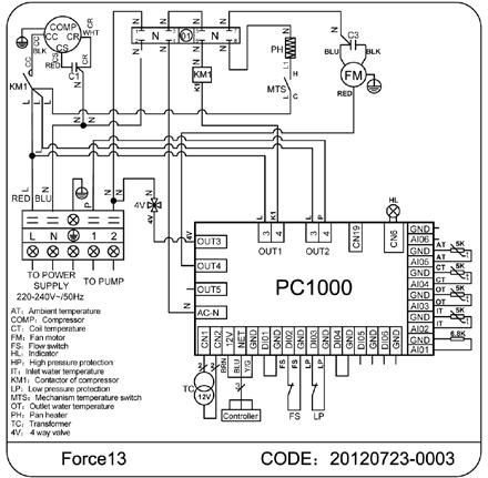
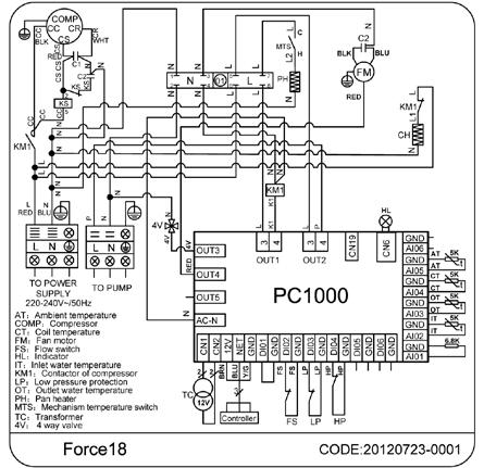
21 Appendix A Wiring Diagrams Appendix A Wiring Diagrams 40 41

22 Appendix A Wiring Diagrams Appendix B Technical Data The heating capacity curve for swimming pool heat pump Force 5 The COP curve for swimming pool heat pump Force
23 Appendix B Technical Data Appendix B Technical Data The heating capacity curve for swimming pool heat pump Force 9 The heating capacity curve for swimming pool heat pump Force 13 The COP curve for swimming pool heat pump Force 9 The COP curve for swimming pool heat pump Force
24 Appendix B Technical Data Appendix B Technical Data The heating capacity curve for swimming pool heat pump Force 18 The heating capacity curve for swimming pool heat pump Force 21 The COP curve for swimming pool heat pump Force 18 The COP curve for swimming pool heat pump Force
25 Appendix B Technical Data The heating capacity curve for swimming pool heat pump Force 25 The COP curve for swimming pool heat pump Force
26 EVOHEAT Pump Warranty 1. The titanium heat exchanger tubing is guaranteed against corrosion for a period of fifteen (15) years from the date of purchase when used with chlorine, salt, bromine or sea water. 2. The compressor is guaranteed for five (5) years from the date of purchase. 3. All other parts are guaranteed for two (2) years from the date of purchase. 4. This warranty covers all labour for twelve (12) months from the date of purchase. Force 5 requires transport back to Evo Industries. 5. This warranty excludes any defect or injury caused by or resulting from misuse, abuse, neglect, accidental damage, improper voltage, vermin infestation, incompetent installation, any fault not attributable to faulty manufacture or parts, any modifications which affect the reliability or performance of the unit. 6. This warranty does not cover the following: a. Natural Disasters (hail, lightening, flood, fire etc.) b. Rust or damage to paintwork caused by a corrosive atmosphere c. When serviced by an unauthorized person without the permission of Evo Industries Australia d. When a unit is installed by an unqualified person e. Where a unit is incorrectly installed f. When failure occurs due to improper or faulty installation g. Failure due to improper maintenance (refer Operating Instructions) h. No Fault Found service calls where the perceived problem is explained within the Operation Instructions i. Costs associated with delivery, handling, freighting, or damage to the product in transit. 7. If warranty service is required you should: a. contact Evo Industries Australia on or via our Contact Us page on our web site b. provide a copy of your receipt as proof of purchase c. have completed the online warranty registration or provide a completed warranty card. 8. Home service is available within the normal operating area of your Evo Industries authorized Service Centre. Service outside this area will incur a travelling fee. Unless otherwise specified to the purchaser, the benefits conferred by this express warranty and additional to all other conditions, warranties, rights and remedies expressed or implied by the Trade Practices Act 1974 and similar consumer protection provisions contained in legislation of the States and Territories and all other obligations and liabilities on the part of the manufacturer or supplier and nothing contained herein shall restrict or modify such rights, remedies, obligations or liabilities. Warranty Registration To register your Warranty, please enter the following details or go online at to register directly at our website. Fields with a star (*) must be filled in before continuing. For information about what Evo Industries Australia will do with your personal details, please refer to our Privacy Disclaimer. Family Name: * Given Name: * Preferred Title: * Age Group: * Street Address: * Suburb: * Postcode: * State: * * Please tell us about which EvoHeat product you bought, who you bought it from and what you will be using it for. Product & Model: * Serial Number: Authorised Installer: Date Purchased: * Date Installed: Receipt Number: * Company you bought it from: * Did you purchase the item when you purchased your pool?: If you purchased it after the pool, how many years did you wait?: What size is your pool or spa?: Why did you choose an EVOHEAT product?: 50 51


27 52
Instruction manual Harmo PAC ZVWX1017/1022/1032/1041/1055/1056/1061
 Instruction manual Harmo PAC ZVWX1017/1022/1032/1041/1055/1056/1061 Imported by: Zwembad BVBA Industrieweg 9 3190 Boortmeerbeek België www.harmopool.eu 0 Table of content Introduction... 2 Safety instructions...
Warning: 230V / 1ph / 50Hz V / 3ph / 50Hz. Remarks: Make sure that you have enough power. (See page 15 Cable table)
") 1 2 Warning: - Do not place your hand or any other objects into the air outlet and fan. It could damage the heat pump and cause injuries; - In case of any abnormality with the heat pump, cut off the power
1 2 Warning: - Do not place your hand or any other objects into the air outlet and fan. It could damage the heat pump and cause injuries; - In case of any abnormality with the heat pump, cut off the power
Owner s Manual for Swimming Pool Heat Pump
 Owner s Manual for Swimming Pool Heat Pump FC Series nirvanahp.com CONTENTS How it works 1 Installation 2 3 Settings 4 5 6 7 Start-up 8 Winterizing 9 Maintenance 10 Troubleshooting 11 12 13 Warranty 14
OWNER S MANUAL. Vintage Classic HEAT COOL models. Proudly Made in the USA
 OWNER S MANUAL Vintage Classic HEAT COOL models Proudly Made in the USA support@aquacomfort.com www.aquacomfort.com/service-and-support 888-475-7443 Manufacturing High Quality, High Efficiency Heat Pump
Surna 25-Ton Chiller Operating & Maintenance Manual
 www.surna.com 303.993.5271 Surna 25-Ton Chiller Operating & Maintenance Manual Models: 300F3-3. 300F4-3, 300FW-3 Revised: July 2015 Table of Contents Warranty Information 4 Limited Warranty 4 Limitation
Swimming Pool Heat Pump
 Swimming Pool Heat Pump Operation and Installation Manual MODEL FH-020 CONTENTS INTRODUCTION Index............ 2 The unit...... 2 SAFETY INSTRUCTIONS... 4 Electrical Installation Warning.. 4 Location Warning
INSTALLATION AND USER MANUAL
 INSTALLATION AND USER MANUAL Thank you for choosing our product and trusting our company. This manual is to provide you with necessary information for optimal use and maintenance, please read carefully
INSTALLATION AND USER MANUAL
 INSTALLATION AND USER MANUAL t Thank you for choosing Aqua inverter heat pump. This manual provides you necessary information for optimal use and maintenance, please read it carefully and keep it for subsequent
OWNER S MANUAL. Models: AC110, AC125, AC150 made from 2003 through Proudly Made in the USA
 OWNER S MANUAL Models: AC110, AC125, AC150 made from 2003 through 2010 Proudly Made in the USA support@aquacomfort.com www.aquacomfort.com/service-and-support/ (888) 475-7443 Manufacturing High Quality,
Swimming Pool Heat pump Instruction manual Harmo PAC series (Type ZVWX1017, ZVWX1023, ZVWX1033, ZVWX1042, ZVWX1052, ZVWX1057, ZVWX1062)
") Swimming Pool Heat pump Instruction manual Harmo PAC series (Type ZVWX1017, ZVWX1023, ZVWX1033, ZVWX1042, ZVWX1052, ZVWX1057, ZVWX1062) Imported by : Zwembad BVBA Industrieweg 9 3190 Boortmeerbeek België
Swimming Pool Heat pump Instruction manual Harmo PAC series (Type ZVWX1017, ZVWX1023, ZVWX1033, ZVWX1042, ZVWX1052, ZVWX1057, ZVWX1062) Imported by : Zwembad BVBA Industrieweg 9 3190 Boortmeerbeek België
SWIMMING POOL & SPA HEAT PUMPS OWNERS OPERATIONAL MANUAL
 SWIMMING POOL & SPA HEAT PUMPS OWNERS OPERATIONAL MANUAL MODEL AT105 AT115 AT130 with Titanium Heat Exchanger 2213 Andrea Lane Ft. Myers FL 33912 888-297-3826 941-482-0606 www.aquathermheatpumps.com DIGITAL
SWIMMING POOL HEAT PUMP UNIT ECO - series. Installation & Instruction manual
 SWIMMING POOL HEAT PUMP UNIT ECO - series Installation & Instruction manual Rev. 1.00 28.11.2007 Contents SWIMMING POOL HEAT PUMP UNIT 1 CONTENTS 2 1. PREFACE 3 2. SPECIFICATIONS 4 2.1 Performance data
SWIMMING POOL HEAT PUMP UNIT Installation & Instruction Manual Duratech - series
 SWIMMING POOL HEAT PUMP UNIT Installation & Instruction Manual Duratech - series Rev. 3.32 26.01.2007 CONTENTS 1. Preface 3 2. Specifications 4 2.1 Performance Data of swimming Pool Heat Pump Unit 4 2.2
INSTALLATION AND USER MANUAL
 INSTALLATION AND USER MANUAL Thank you for choosing inverter heat pump. This manual provides you necessary information for optimal use and maintenance, please read it carefully and keep it for subsequent
Quick Start Guide. For product manuals and further installation / operation procedures visit
 Quick Start Guide For product manuals and further installation / operation procedures visit www.aquacal.com Important Read This Guide Before Installing or Operating Heat Pump LTP0093 Rev 1 03/21/2014 Page
SPA HEATER INSTALLATION, OPERATION AND MAINTENANCE
 SPA INSTALLATION, OPERATION AND MAINTENANCE MODELS: ST SERIES 5.5 & 11kW 240V SINGLE PHASE BEFORE YOU BEGIN CHECK ALL ELECTRICAL CONNECTIONS TO ALL COMPONENTS WITHIN THE FOR TIGHTNESS. CONNECTIONS CAN
INSTALLATION/OPERATING INSTRUCTIONS. AQUEFIER POOL HEATERS Model TK125T
 INSTALLATION/OPERATING INSTRUCTIONS FOR AQUEFIER POOL HEATERS Model TK125T Trevor-Martin Corp., 4151 112 th Terrace North, Clearwater, FL 33762 Bulletin PH-125T Rev. 3 1 IMPORTANT SAFETY INSTRUCTIONS READ
Spa Control System OWNER S MANUAL
 LIMITED WARRANTY ONE YEAR LIMITED WARRANTY: UNITED SPAS, INC. warrants, to the original purchaser, the Spa Equipment against defects in materials or workmanship for a period of one year from date of purchase.
ECO SPA & POOL OWNERS MANUAL & INSTALLATION GUIDE
 ECO SPA & POOL OWNERS MANUAL & INSTALLATION GUIDE MODELS: ECO SPA 5.5-11 / ECO POOL 18-27 IMPORTANT SAFETY INSTRUCTIONS,INSTALLATIONIN STRUCTIONS,USER INSTRUCTIONS As when installing or using any high
Harmo Powerpack Horizontal Units Installation & instruction manual
 Imported by: Zwembad BVBA Industrieweg 9 3190 Boortmeerbeek België www.harmopool.eu Harmo Powerpack Horizontal Units Installation & instruction manual Table of content Introduction... 3 Characteristics...
OWNER S MANUAL HIGH WALL INVERTER. (English) (BSHVD1S SERIES)
 (BSHVD1S SERIES)") OWNER S MANUAL HIGH WALL INVERTER (English) (BSHVD1S SERIES) IMPORTANT As with any product that has moving parts or is subject to wear and tear, it is VERY IMPORTANT that you maintain your air conditioner
OWNER S MANUAL HIGH WALL INVERTER (English) (BSHVD1S SERIES) IMPORTANT As with any product that has moving parts or is subject to wear and tear, it is VERY IMPORTANT that you maintain your air conditioner
OWNER S MANUAL. Vintage Signature Series models: AC750, AC1050, AC1100, AC1250, AC1500, AC1750. Proudly Made in the USA.
 OWNER S MANUAL Vintage Signature Series models: AC750, AC1050, AC1100, AC1250, AC1500, AC1750 Proudly Made in the USA support@aquacomfort.com 888-475-7443 Manufacturing High Quality, High Efficiency Heat
INSTALLATION AND USER MANUAL
 Swimming Pool Heat Pump Swimming Pool Heat Pump INSTALLATION AND USER MANUAL Thank you for choosing our product and trusting our company. This manual is to provide you with necessary information for optimal
Owner s Manual PRINTED IN CANADA 05/2009
 Owner s Manual PRINTED IN CANADA 05/2009 Table of contents Introduction 2 General Safety Instructions 4 Installation Instructions Location 6 Water piping 7 Electrical 7 Bonding 8 Bonding and plumbing
5) Do not start or stop the unit by inserting or pulling out the power plug.
 Do not start or stop the unit by inserting or pulling out the power plug.") 3058080 V170306 PURCHASE INFORMATION Thank you for choosing a Soleus Air Portable Air Conditioner. This Owner s Manual will provide you with valuable information necessary for the proper care and maintenance
3058080 V170306 PURCHASE INFORMATION Thank you for choosing a Soleus Air Portable Air Conditioner. This Owner s Manual will provide you with valuable information necessary for the proper care and maintenance
Model No.: PS08-01 PS10-01 Ref: KY80 KY100
 8,000/10,000/12,000 BTU Portable Air Conditioner Operating Instructions Model No.: PS08-01 PS10-01 Ref: KY80 KY100 Model No.: PS12-03 Ref: KY120 3119233 V160310 Thank you for choosing a Soleus Air Portable
Contents. Specifications. Description SV HP 55 SV HP 90. Specifications Warnings Introduction Overview... 4
 Contents Specifications Specifications... 1 Warnings... 2 Introduction... 3 Overview... 4 Installation Instructions... 5 Cable Connections... 6 Plumbing Diagram... 7 Electrical Wiring Diagram... 8 SV System
Heat Pumps. English. Models: M1, M2, M3, M4, M5. User Manual
 English User Manual Heat Pumps Models: M1, M2, M3, M4, M5 For product manuals and further installation operation procedure contact poolcalor@yahoo.com.br S E C T I O N 1 - G E N E R A L I N F O R M AT
HP50HA ABG Heat Pump
 HP50HA ABG Heat Pump Troubleshooting Guide Residential TSG-ABGHPa Copyright 2017 Hayward Industries Inc. Safety Precautions Warning! High Voltage Electrocution Hazard Hazardous voltage can shock, burn,
SWIMMING POOL HEAT PUMP UNIT Installation & Instruction Manual
 SWIMMING POOL HEAT PUMP UNIT Installation & Instruction Manual OASIS C10 HEAT PUMP Head Office 62 Parkhurst Drive Knoxfield VIC 3180 T: 03 9887 2131 New South Wales Unit 1, 20-22 Foundry Road Seven Hills
Swimming Pool Heat Pump
 Swimming Pool Heat Pump - Operation and Installation Manual - Model:LCSPI-95BP,LCSPI-135BP,LCSPI-180BP, LCSPI-220BP, LCSPI-280BP TABLE OF CONTENT INTRODUCTION...... 2 This manual... 2 The Heat Pump...
FREWIN STEAM SHOWER ENCLOSURE
 FREWIN STEAM SHOWER ENCLOSURE INSTALLATION AND USER MANUAL CONTENTS Steam Shower Enclosure Installation...2 Technical Information...2 Plumbing Requirements...2 Assembly...3 Tools and Materials...3 Installation...3
OWNER S MANUAL HIGH WALL INVERTER. (English) (MSHVD1S SERIES)
 (MSHVD1S SERIES)") OWNER S MANUAL HIGH WALL INVERTER (English) (MSHVD1S SERIES) IMPORTANT As with any product that has moving parts or is subject to wear and tear, it is VERY IMPORTANT that you maintain your air conditioner
OWNER S MANUAL HIGH WALL INVERTER (English) (MSHVD1S SERIES) IMPORTANT As with any product that has moving parts or is subject to wear and tear, it is VERY IMPORTANT that you maintain your air conditioner
SWIMMING POOL HEAT PUMP UNIT. Installation & Instruction Manual
 SWIMMING POOL HEAT PUMP UNIT Installation & Instruction Manual CONTENTS. Preface. Specifications. Performance Data of Swimming Pool Heat Pump Unit. Dimensions for Swimming Pool Heat Pump Unit 3. Installation
Portable Air Conditioner 6,000 BTU 8,000 BTU 10,000 BTU
 Portable Air Conditioner 6,000 BTU 8,000 BTU 10,000 BTU OPERATING INSTRUCTIONS PCR-06-01 PCR-08-01 PCR-10-01 3058080 V170223 PURCHASE INFORMATION Thank you for choosing a Chigo Portable Air Conditioner.
TRANQUILITY ADVANCED HEATING SYSTEM
 TRANQUILITY ADVANCED HEATING SYSTEM MODELS: PBES-6010 PBES-6040 1000W Advanced Heating System 4000W Advanced Heating System Operation / Installation Instructions 85-0059-G Rev.03-6/13 INTRODUCTION The
Portable Dehumidifier
 Portable Dehumidifier OPERATING INSTRUCTIONS HMT-D30-A Model Numbers: HMT-D30-A HMT-D45E-A HMT-D70E-A HMT-D45E-A HMT-D70E-A 3058080 V.161115 PURCHASE INFORMATION Thank you for choosing a Soleus Air Portable
Model No. GB-PAC-08E4. 8,000 BTU Portable Air Conditioner Operating Instructions
 Model No. GB-PAC-08E4 8,000 BTU Portable Air Conditioner Operating Instructions Thank you for choosing a Soleus Air Powered by Gree Portable Air Conditioner. This owner s manual will provide you with valuable
USER MANUAL. Adventure Kings WiFi Refrigerator
 Adventure Kings WiFi Refrigerator USER MANUAL Please read and understand these instructions and the safety information section before using your refrigerator. CONTENTS Safety Information 1 Notes on using
OPERATION MANUAL. Daikin Altherma indoor unit EKHVMRD50ABV1 EKHVMRD80ABV1 EKHVMYD50ABV1 EKHVMYD80ABV1
 OPERATION MANUAL EKHVMRD50ABV1 EKHVMRD80ABV1 EKHVMYD50ABV1 EKHVMYD80ABV1 EKHVMRD50+80ABV1 EKHVMYD50+80ABV1 CONTENTS Page 1. Definitions... 1 2. Introduction... 2 2.1. General information... 2 2.2. Scope
AquaCal Operation Manual
 AquaCal Operation Manual WATER CHILLER Important Read this document before operating / installing this product For additional product manuals and operation / installation procedures, please visit www.aquacal.com
User instructions DHP-AT
 User instructions DHP-AT VUGFC202 If these instructions are not followed during installation and service, Danfoss A/S liability according to the applicable warranty is not binding. Danfoss A/S retains
ARLEY STEAM SHOWER ENCLOSURE
 ARLEY STEAM SHOWER ENCLOSURE INSTALLATION AND USER MANUAL CONTENTS Steam Shower Enclosure Installation...2 Technical Information...2 Plumbing Requirements...2 Assembly...3 Tools and Materials...3 Installation...3
LEVENS STEAM SHOWER ENCLOSURE
 LEVENS STEAM SHOWER ENCLOSURE INSTALLATION AND USER MANUAL CONTENTS Steam Shower Enclosure Installation...2 Technical Information...2 Plumbing Requirements...2 Assembly...3 Tools and Materials...3 Installation...3
HMT-D30-A HMT-D45E-A HMT-D70E-A. Model Numbers: HMT-D30-A HMT-D45E-A HMT-D70E-A. Portable Dehumidifier Operating Instructions V.
 HMT-D30-A HMT-D45E-A HMT-D70E-A Model Numbers: HMT-D30-A HMT-D45E-A HMT-D70E-A Portable Dehumidifier Operating Instructions 3119233 V.141217 General Dehumidifier Information RECOMMENDED HUMIDITY LEVELS
Portable Dehumidifier with Internal Pump
 Portable Dehumidifier with Internal Pump OPERATING INSTRUCTIONS 115 Pint Portable Dehumidifier With Internal Pump Model Number: DMC-115IP-210 3092402 V161220 PURCHASE INFORMATION Thank you for choosing
USER MANUAL. Adventure Kings 50L Refrigerator
 Adventure Kings 50L Refrigerator USER MANUAL Please read and understand these instructions and the safety information section before using your refrigerator. CONTENTS Safety Information 1 Notes on using
Sunleaves Air Conditioner
 Sunleaves Air Conditioner Thank you for purchasing this quality Sunleaves Air Conditioner! Please read through this manual completely, and keep it in case you need to reference the information in the future.
HMT-D30-A HMT-D45E-A HMT-D70E-A. Model Numbers: HMT-D30-A HMT-D45E-A HMT-D70E-A. Portable Dehumidifier Operating Instructions V.
 HMT-D30-A HMT-D45E-A HMT-D70E-A Model Numbers: HMT-D30-A HMT-D45E-A HMT-D70E-A Portable Dehumidifier Operating Instructions 3058080 V.151201 General Dehumidifier Information RECOMMENDED HUMIDITY LEVELS
OWNER S Manual PRINTED IN CANADA 10/2009
 OWNER S Manual PRINTED IN CANADA 10/2009 Table of contents Introduction 2 General Safety Instructions 4 Installation Instructions Location 6 Water piping 7 Electrical 7 Bonding 8 Bonding and plumbing
E-COMBI EVO E-SYSTEM EVO
 E-COMBI EVO E-SYSTEM EVO User s manual CONDENSING WALL-HUNG GAS BOILER G.C.N.:47-116-68 (24 kw) G.C.N.:47-116-69 (30 kw) G.C.N.:47-116-70 (38 kw) G.C.N.:41-116-39 (24 kw) G.C.N.:41-116-40 (30 kw) Country
Instruction Manual. Please read this manual and the Safety Instructions carefully before using your refrigerator.
 Nexberg Pty Ltd T/a Evakool 16 Enterprise St CALOUNDRA QLD 4551 Tel : 07 5492 7777 Fax : 07 5492 7733 Please read this manual and the Safety Instructions carefully before using your refrigerator. 1. Safety
!3 _!!ili_ '_:_i_;iii_ SG-PAC-12E1 SG-PAC- 12E 1HP. 12,000 BTU Portable Air Conditioner
 _'_j_ii_yg, CI_ ' _i_,_!3 _!!ili_ '_:_i_;iii_ SG-PAC-12E1 SG-PAC- 12E 1HP 12,000 BTU Portable Air Conditioner Operatin! nstructions Thank you for choosing a Soleus Air Powered by Gree Portable Air Conditioner.
INSTALLATION, OPERATION AND MAINTENANCE
 POOL HEATER INSTALLATION, OPERATION AND MAINTENANCE MODELS: PHS-CN SERIES, 5, 8, 4, 0, 6, 45, 54 & 57kW 08V, 40V, 480, 600V SINGLE & THREE PHASE BEFORE YOU BEGIN CHECK ALL ELECTRICAL CONNECTIONS TO ALL
AquaCal Operation Manual
 AquaCal Operation Manual Important Read this document before operating / installing this product For additional product manuals and operation / installation procedures, please visit www.aquacal.com LTM0883
Swedish design and manufacture since 1967
 Swedish design and manufacture since 167 PVP MA20-14 rev.2 Manual User manual Copyright 2017 Pahlén AB, Box 728, SE-14 27 Upplands Väsby, Sweden Tel. +46 8 54 110 50, Fax +46 8 50 868 80, e-mail: info@pahlen.se,
AquaCal Operation Manual
 AquaCal Operation Manual AND Important Read this document before operating / installing this product For additional product manuals and operation / installation procedures, please visit www.aquacal.com
User s Information Manual Models: ER152, ER202, ER252, ER302, and ER402
 ERP-USER_100161005_2000003726_Rev D User s Information Manual Models: ER152, ER202, ER252, ER302, and ER402 If the information in this manual is not followed exactly, a fire or explosion may result causing
TRAVELMATE. Instruction Manual
 Nexberg Pty Ltd T/a Evakool 16 Enterprise St CALOUNDRA QLD 4551 Tel : 07 5492 7777 Fax : 07 5492 7733 Please read these instructions and the Safety Instructions carefully before using your refrigerator.
Model Numbers: HCT-D30-A (TDA30) HCT-D45E-A (TDA45E) HCT-D70E-A (TDA70E) Portable Dehumidifier Operating Instructions V
 HCT-D45E-A (TDA45E) HCT-D70E-A (TDA70E) Portable Dehumidifier Operating Instructions V") Model Numbers: HCT-D30-A (TDA30) HCT-D45E-A (TDA45E) HCT-D70E-A (TDA70E) Portable Dehumidifier Operating Instructions 3119233 V.140529 General Dehumidifier Information RECOMMENDED HUMIDITY LEVELS Spring/Summer:
Model Numbers: HCT-D30-A (TDA30) HCT-D45E-A (TDA45E) HCT-D70E-A (TDA70E) Portable Dehumidifier Operating Instructions 3119233 V.140529 General Dehumidifier Information RECOMMENDED HUMIDITY LEVELS Spring/Summer:
Portable Air Conditioner, Dehumidifier,Heater and Fan utilizing Heat Pump Technology
 Portable Air Conditioner, Dehumidifier,Heater and Fan utilizing Heat Pump Technology OWNER'S MANUAL Model # KY-34 3046364 Please read owner s manual carefully before operating unit. TABLE OF CONTENTS INTRODUCTION...3
POOL HEATER INSTALLATION, OPERATION AND MAINTENANCE
 POOL HEATER INSTALLATION, OPERATION AND MAINTENANCE MODELS: TR SERIES, 5 & 8kW 08V, 40V, 480V, 600V BEFORE YOU BEGIN CHECK ALL ELECTRICAL CONNECTIONS TO ALL COMPONENTS WITHIN THE HEATER FOR TIGHTNESS.
11,000 BTU Portable Air Conditioner with dehumidifier & Fan PE4-11R-03 Operating Instructions. Model No. PE4-11R Soleus Air International
 11,000 BTU Portable Air Conditioner with dehumidifier & Fan PE4-11R-03 Operating Instructions Model No. PE4-11R-03 2006 Soleus Air International Thank you for choosing a Soleus Air Portable Air Conditioner.
Accent User. Version. Rheem. PO Box 146, ABN:
 Accent Heat Pump Tariff Controller User Manual Version 1.0 21 Atkinson Street, Liverpool NSW 2170 PO Box 146, Moorebank NSW 1875 ABN: 28 062 383 224 ACN: 062 383 224 Rheem Pool Heating Advisory: 1300 132
Prime Chiller Modular Upgradable Chiller
 Prime Chiller Modular Upgradable Chiller Instructions for Models Single Stage Thermostat #2604, 2606 Dual Stage Thermostat #2614, 2616 Single Stage Thermostat w/ TXV #2626, 2627 Warning and Safety Instructions...
Prime chiller. Inline Chiller. Instructions for Models #2645,2646
 Prime chiller Inline Chiller Instructions for Models #2645,2646 Warning and Safety Instructions... Page 2 Chiller Installation... Page 3 Temperature Controller Programming... Page 5 Warranty... Page 7
This manual should be maintained in legible condition and kept adjacent to the heat pump or in a safe place for future use.
 Perfectemp Swimming Pool Heat Pump CE OWNER S MANUAL Models PT4, PT6, and PT8 R C LISTE D 9900276 US This manual should be maintained in legible condition and kept adjacent to the heat pump or in a safe
This manual should be maintained in legible condition and kept adjacent to the heat pump pool heater or in a safe place for future use.
 INSTALLATION & OPERATING INSTRUCTIONS Heat Pump Pool & Spa Heater Model Series 5350, 6350, 6350HC & 8350 New R-410A Product C LISTE D R US FOR YOUR SAFETY: Do not store or use gasoline or other flammable
Whirlpool Bathtub Model Number: MT618
 INSTALLATION AND OWNER'S MANUAL Whirlpool Bathtub Model Number: MT618 Please carefully read these instructions before you begin to install the products. 07/11 Rev A P/N:100056-03 Thank you for purchasing
G&F Manufacturing Swimming Pool Heat Pump Install & Operations Manual
 G&F Manufacturing Swimming Pool Heat Pump Install & Operations Manual 5005001B Version 5.2 TABLE OF CONTENTS Introduction 3 Water Chemistry Maintenance 5 Installation o Location of Heater 6 o Tie Downs
Instructions for installation
 Instructions for installation Read this notice carefully before installing, maintaining or repairing this appliance! The symbol indicates important information that you must take into account to avoid
SWIMMING POOL HEAT PUMP UNIT. Installation & Instruction Manual
 SWIMMING POOL HEAT PUMP UNIT Installation & Instruction Manual CONTENTS. Preface. Specifications. Performance Data of Swimming Pool Heat Pump Unit. Dimensions for Swimming Pool Heat Pump Unit. Installation
ELECTRIC SPA-PAK HEATER INSTALLATION & OPERATING INSTRUCTIONS
 ELECTRIC SPA-PAK HEATER INSTALLATION & OPERATING INSTRUCTIONS CATALOG NO.: 6100.53O Effective: 03-15-05 Replaces: 02-01-05 INTRODUCTION The SPA-PAK Spa Heaters have been designed to provide efficient,
Model No. CZ2011O Oak Finish CZ2011C Cherry Finish CZ2011W Walnut Finish CZ2011B Black Finish DIGITAL QUARTZ INFRARED HEATER OWNER S MANUAL
 Model No. CZ2011O Oak Finish CZ2011C Cherry Finish CZ2011W Walnut Finish CZ2011B Black Finish DIGITAL QUARTZ INFRARED HEATER OWNER S MANUAL PLEASE SAVE THESE INSTRUCTIONS WARNING: READ THIS OWNER S MANUAL
ThermoSaver TM Hot Gas Defrost System
 PRODUCT DATA, APPLICATION & INSTALLATION GUIDE Supplement to Condensing Unit Installation and Maintenance Manual Bulletin B40-THERM-PDI-14 1069132 ThermoSaver TM Hot Gas Defrost System For use on select
aquamanta the experts in aquatic technology CH 025/050/100/ 150/200/300 NEW PHOTO Instruction Manual
 aquamanta TM the experts in aquatic technology CH 025/050/100/ 150/200/300 NEW PHOTO Instruction Manual Technical Information Model Wattage Aquarium Volume CH 025 CH 050 CH 100 CH 150 CH 200 CH 300 25W
This manual should be maintained in legible condition and kept adjacent to the heat pump pool heater or in a safe place for future use.
 INSTALLATION & OPERATING INSTRUCTIONS Heat Pump Pool & Spa Heater Model Series 2350 R C LISTED US FOR YOUR SAFETY: Do not store or use gasoline or other flammable vapors and liquids or other combustible
Owner's Manual TABLE OF CONTENTS
 40MAQ High Wall Ductless System Sizes 09 to 36 Owner's Manual TABLE OF CONTENTS PAGE A NOTE ABOUT SAFETY... 2 GENERAL... 2 PART NAMES... 3 FUNCTION BUTTONS... 4 DISPLAY PANELS... 5 REMOTE CONTROL... 6
100 Series Maxi Internal Filters
 100 Series Maxi Internal Filters Important Safeguards To guard against injury, basic safety precautions should be observed, including the following: 1. Read and follow all safety instructions and important
CUBE ICEMAKER MODELS SCU25, SCU35, SCU45, SCU75, SCU95, SCU120 INSTALLATION AND SERVICE MANUAL VERSION 2
 CUBE ICEMAKER MODELS SCU25, SCU35, SCU45, SCU75, SCU95, SCU120 INSTALLATION AND SERVICE MANUAL VERSION 2 STUART MANUFACTURING 1 Jayelem Crescent Padstow NSW 2211 Australia Telephone (02) 9773 3711 Fax
POLAR TEMP FARM MORTALITY UNIT OPERATION MANUAL
 POLAR TEMP FARM MORTALITY UNIT OPERATION MANUAL www.polartemp.com TABLE OF CONTENT Disclaimer.......................................... Page 3 Inspection, unpacking and FMU setup.................. Page
MiNI SWIMMING POOL HEAT PUMP UNIT. Installation & Instruction Manual
 MiNI SWIMMING POOL HEAT PUMP UNIT Installation & Instruction Manual 5.Maintenance and inspection 5.1 Maintenance To check the water supply device and the releaser often. You should avoid the condition
Elegance. SMT-700 User manual. Ver
 Elegance SMT-700 User manual Ver 3.0. 0807 Congratulations on the purchase of your new Thermostat! Your new air conditioning system thermostat has been built using the best components and design philosophy
4230/6230/9230 SERIES OWNERS OPERATION GUIDE
 4230/6230/9230 SERIES OWNERS OPERATION GUIDE 104 CONTENTS Important Safety Instructions 2 INTRODUCTION Major Component Illustration 4 SYSTEM OPERATION Features & Function Visual Diagnostic System (VDS)
COMPACT PORTABLE AIR CONDITIONER USER MANUAL
 COMPACT PORTABLE AIR CONDITIONER USER MANUAL Thank you for choosing ElectriQ Please read this user manual before using this innovative Air Conditioner and keep it safe for future reference. Visit our page
POOL & SPA HEATING CATALOGUE YEAR * WARRANTY
 POOL & SPA HEATING CATALOGUE 2017 15 YEAR * WARRANTY ABOUT EVOHEAT HEATING & COOLING TECHNOLOGY EvoHeat are 100% Australian owned and operated company and are the industry specialists in pool and spa heating
Installation and Operating Manual
 Installation and Operating Manual SR868C6 System Regulator for Solar Thermal Systems Display Panel Illustration Pos. Button on display panel Button description 1 Green lamp Power indication lamp 2 On/Off
ULT L IMAT A E SERIES SOLID-STA T T A E SYSTEM OPERAT A ION MANUAL 8600
 ULTIMATE SERIES SOLID-STATE SYSTEM OPERATION MANUAL 8600 CONTENTS Important Safety Instructions 2 INTRODUCTION Major Component Illustration 4 SYSTEM OPERATION Heater Operation Spaside Control Spa Light
CPS-1 USER S MANUAL AIR INLET / CURTAIN CONTROL
 CPS-1 USER S MANUAL AIR INLET / CURTAIN CONTROL temperature / static pressure DIFF Opn Clo ALARM HI F2 DELAY ALARM LO OPEN DELAY CLOSE ADJUST Varifan + CPS-1 CPS-1 Although the manufacturer has made every
Portable Air Conditioner with Heat Pump Technology Operating Instructions. Model No.: HCB-P13HP-D. Reference No.: BPD13HP V140217
 Portable Air Conditioner with Heat Pump Technology Operating Instructions 3092402 Model No.: HCB-P13HP-D Reference No.: BPD13HP V140217 Thank you for choosing a Soleus Air Portable Air Conditioner with
Index. Index. Heatseeker Nova Inverter Heat Pump. Heatseeker Nova Inverter Heat Pump. supremeheating.com.au
 Index Heatseeker Nova Index Heatseeker Nova Index Index 1. GENERAL INFORNMATION 1 1.1 Introduction to Heatseeker Nova 1 1.2 Consumer and Safety Infornmation 2 2. SPECIFICATIONS 3 2.1 Technical Specifications
Instruction Manual. Please read these instructions and the Safety section carefully before using your refrigerator.
 Nexberg Pty Ltd T/a Evakool 16 Enterprise St CALOUNDRA QLD 4551 Tel : 07 5492 7777 Fax : 07 5492 7733 Please read these instructions and the Safety section carefully before using your refrigerator. 1.Safety
NON-CYCLING REFRIGERATED AIR/GAS DRYERS QPNC 75 to QPNC 250 OPERATOR S MANUAL
 NON-CYCLING REFRIGERATED AIR/GAS DRYERS QPNC 75 to QPNC 250 OPERATOR S MANUAL DATE OF PURCHASE: MODEL: SERIAL NO.: Record above information from nameplate. Retain this information for future reference.
INSTALLATION & USER MANUAL NATIONAL. Heatseeker VortexPro Inverter Heat Pump Installation & User Manual 1
 INSTALLATION & USER MANUAL NATIONAL Installation & User Manual 1 Head Office Bundoora VIC 3083 P: (03) 9460 4200 info@supremeheating.com.au NSW Office Smeaton Grange NSW 2567 P: (02) 4648 4766 solar.nsw@supremeheating.com.au
HTD. High Temperature Non-Cycling Refrigerated Compressed Air Dryers. Operation & Maintenance Manual. MODELS HTD 21 thru HTD 100
 HTD High Temperature Non-Cycling Refrigerated Compressed Air Dryers Operation & Maintenance Manual MODELS HTD 21 thru HTD 100 - TABLE OF CONTENTS - 1.0 GENERAL 2 1.1 How to use this manual 1.2 Symbols
Table of Contents. Features Quality Policy Section A - Unit Operation Section B Unit Maintenance Trouble Shooting Guide...
 Table of Contents Features... 3 Quality Policy... 3 Section A - Unit Operation... 4 Section B Unit Maintenance... 6 Trouble Shooting Guide... 7 Wiring Diagram... 9 Section C Unit Installation... 9 Unit
SILENT 12 PORTABLE AIR CONDITIONER USER MANUAL
 SILENT 12 PORTABLE AIR CONDITIONER USER MANUAL Thank you for choosing ElectriQ Please read this user manual before using this innovative Air Conditioner and keep it safe for future reference. Visit our
Instruction Manual. By Evakool. Please read these instructions and the Safety section carefully before using your refrigerator.
 Nexberg Pty Ltd T/a Evakool 16 Enterprise St CALOUNDRA QLD 4551 Tel : 07 5492 7777 Fax : 07 5492 7733 Please read these instructions and the Safety section carefully before using your refrigerator. 1.Safety
Portable Air Conditioner with Heat Pump Technology PH4-10R-01, PH4-12R-01, & PH4-14R-01 Operating Instructions
 Portable Air Conditioner with Heat Pump Technology PH4-10R-01, PH4-12R-01, & PH4-14R-01 Operating Instructions 3092402 2006 Soleus Air International Thank you for choosing a Soleus Air Portable Air Conditioner
15,000 BTU Portable Air Conditioner
 Instruction Manual 15,000 BTU Portable Air Conditioner Model: HYAC15 READ AND SAVE THESE INSTRUCTIONS Please read and follow the instructions in this user manual even if you feel you are familiar with