Installation and Troubleshooting Instructions for Electric Tankless Commercial Water Heaters CE 12 KW, CE 15 KW, CE 18 KW CE 24 KW CE 27 KW CE 48 KW
|
|
|
- Kelley Harmon
- 5 years ago
- Views:
Transcription


1 Model Number: Serial Number: Information Manual Rev # Installation and Troubleshooting Instructions for Electric Tankless Commercial Water Heaters CE 12 KW, CE 15 KW, CE 18 KW CE 24 KW CE 27 KW CE 48 KW CES 12 KW,CES 15 KW, CES 18 KW CES 24 KW, CES 27 KW, CES 36 KW CE 120 KW CE 144 KW or CE 108 KW CE 72 KW, CE 54 KW, or CE 48 KW CES 120 KW CES 144 KW or CES 108 KW CES 72 KW, CES 54 KW, or CES 48 KW FOR MORE DETAILED SCHEMATICS AND WIRING DIAGRAMS VISIT, HOTWATERHEATER.COM 2060 B Whitfield Park Avenue * Sarasota, FL * * tanklessinc@stiebel-eltron-usa.com 1
2 Table of Contents INFORMATION MANUAL for Commercial Heaters Models CE 12 KW CES 12 KW CE 15 KW CES 15 KW CE 18 KW CES 18 KW CE 24 KW CES 24 KW CE 27 KW, CES 27 KW, CERO 27 KW, CE 36 KW CES 36 KW CERO 36 KW CE 48 KW CES 48 KW CE 54 KW, CES 54 KW, CERO 54 KW, CERO 72 KW, CE 72 KW. CES 72 KW, CE 108 KW, CES 108 KW, CE 120 KW, CES 120 KW, CE 144 KW, CES 144 KW PAGE # How a CE and CES Series Heaters Work 3 Controls Explanation 4 Engineering Information and Breaker Sizes 5 Recovery Capacities Chart 6 CE Series Installation 7 Assembly Drawing 12 KW 15 KW or 18 KW 8 Assembly Drawing 24 KW 27 KW 36 KW 9 Assembly Drawing 48 KW 54 KW 72 KW 10 Assembly Drawing 108 KW 120 KW 144 KW 11 Troubleshooting electronic three phase units
3 How an electronic Heater Works: We have four lines of heaters; electromechanical (C series) and electronic (CE series), electronic (CES), and CERO series. They all heat the fluid as it passes through but they are controlled in different manners depending on the customer s needs. This manual is specifically for the CE, CES, or CERO series units..3, 6, 12 element or 24 element units for the CE and CES series and 3,6,and 12 for the CERO units. CE, CES, and CERO models: These models use a computer board to control the heating process. They need three pieces of information to determine how much heat is necessary. 1. Water flow- This is determined by the flow meter and the information sent to the board. When the water tap opens, the cold water entering the heater passes through the Flow Meter and the Flow Meter calculates how much water is passing through the heater and it sends the signal to the Control Board once a second. 2. Inbound fluid temperature- A thermistor reads the inbound temperature of the water and sends a signal to the Control Board. 3. Desired output temperature. The customer provides this information and can adjust the level using the rocker switch at the left side of the unit for the 12 kw,15 kw, 18 kw, 36 kw, 48 kw, 54 kw, and 72 kw units and using either the buttons on the board or the rocker switch on the right side for the 108 KW, 120 KW, or the 144 KW units. 4. On the CE and CERO series the acceptable temperature range the computer board will accept is F and on the CES series the output temperature is limited to 90 F. 5. The thermostats that shut down heating on the CE and CERO units are 200 F and on the CES series this mechanical over temperature protection is at 90 F. The Control Board takes the information given by the Flow Meter, the thermistor, and the customer and calculates every second how many BTUs it needs to apply to the water to achieve the desired temperature and turns on the appropriate number of elements. Each time the unit turns on the series in which the elements turn on changes to balance out the element usage and to increase the element life. This function is called dynamic load balancing. The CERO units use special elements with titanium sheathing so be sure to order the correct part if you have a CERO model. 3

4 Controls Explanation CE, CES and CERO Series models Options for factory software settings include the following items Commercial water heaters Safety shower heaters CE and CERO Maximum temperature: 60 to 185 F 60 to 90 F Initial output setting per customer request 85 F Freeze protection at 40 degrees F Yes Yes For use on a recirculation system Yes No F or C F F Flashing to show over capacity condition Yes Yes Shows output temperature and Requested output temperature intermittently Each 60 seconds Yes Yes RS 232 interface available Yes Yes CES 4
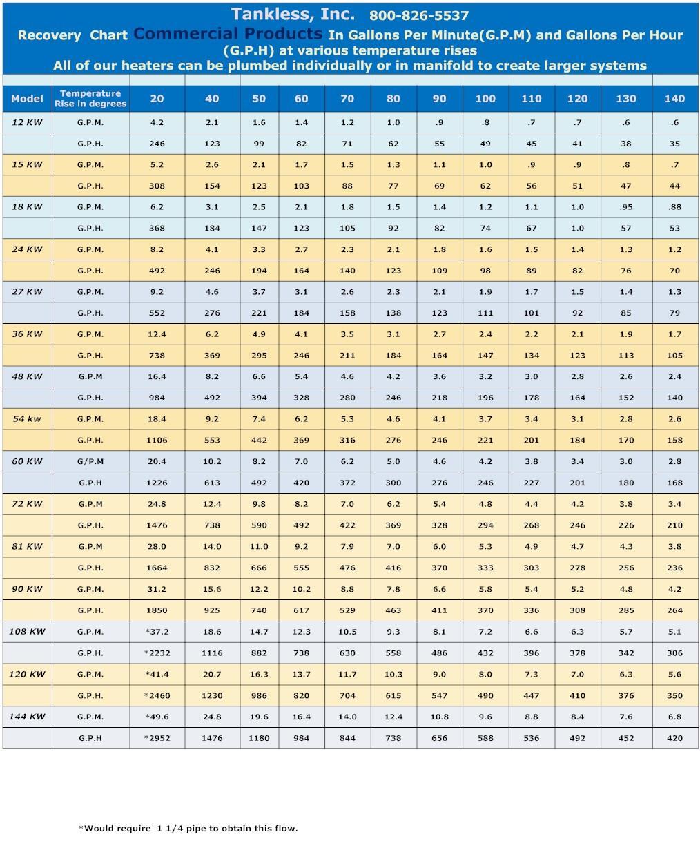
 and the capabilities of each unit(recovery chart) in terms of temperature rise at a certain flow")
5 The following charts show the full load AMP draw, breakers required and physical size for each of our larger electronic units (engineering chart) and the capabilities of each unit(recovery chart) in terms of temperature rise at a certain flow rate. 5
6 6
7 Installation of electronic water heaters. 1. Please review the engineering chart on page 5 for breakers needed and verify the voltage marked on the heater is what you have at your facility. 2. Each unit has a set of brackets or C channel to mount to the floor. Attach the unit to the wall using the brackets supplied with the unit. 3. Connect the pipe to the inbound and outbound side of the heater which is clearly marked. Hot is on the top and cold on the bottom. 4. Attach the pressure relief valve to a line piped to the outside or a drain. 5. Test for leaks by flowing water thru the unit. 6. Each three phase unit has a distribution block with room for three hot lines and a separate spot for the ground. Attach each unit to its separate disconnect using this block and cable supplied by the installer and be sure the wires are tightly connected. The CE 108 KE has a disconnect for two CE 54 KW units and the CE 144 KW unit has a disconnect for two CE 72 W units. 7. Attach the compressed air connection to the purge system per the attached purge system manual. 8. Connect electrical requirements for the purge system if applicable. This is applicable if the user will need power to drive an external alarm. 9. Flow water thru the unit. 10. Check the settings on the delay switch in the unit. Factory settings are 1 meaning one minute. The unit will turn on 1 minute after you have power to the unit and the water pressure is above 3 PSI. 11. Check kill switch to insure it is in the off/(pushed in)position, if applicable. 12. Turn on the toggle switches to the unit/s; #10 in the picture on page Close the door or replace the front cover. 14. Perform the enclosure purge function in accordance with the enclosed purge system manual if applicable. 15. Turn on the breaker to the unit. 16. Monitor the output fluid temperature after 1 minute. 17. After seconds view the temperature reading on the computer board thru the front cover or door. 18. The unit will have gone thru its diagnostics on the software and the LED screen will show various messages. Once the temperature setting shows on the LED screen the unit is ready to be adjusted as to the temperature output desired. 19. Set the unit to the output temperature you desire using the rocker switch at the left of the unit or the right if in a NEMA 4 enclosure. Click on the top to increase the temperature or on the bottom to reduce the temperature. 20. Replace the front cover or close the door. 21. Perform the enclosure purge function in accordance with the enclosed purge system manual if applicable. 22. Unit is now fully operational. 7
8 Assembly Drawing for CE 12 KW CE 15 KW CE 18 KW CES 12 KW, CES 15 KW, CES 18 KW 8

9 Assembly Drawing for CE 24 KW CE 27 KW or CE 36KW CERO 27 KW and CERO 36 KW CES 24 KW CES 27 KW CES 36 KW 9

10 Assembly Drawing for CE 72 or CE 54 or CE 48 KW CERO 72 KW or CERO 54 KW CES 48 KW CES 54 KW CES 72 KW 10
11 Assembly Drawing for CE 108 KW CE 120 KW or CE 144 KW..CES 108 KW CES 120 KW CES 144 KW 11
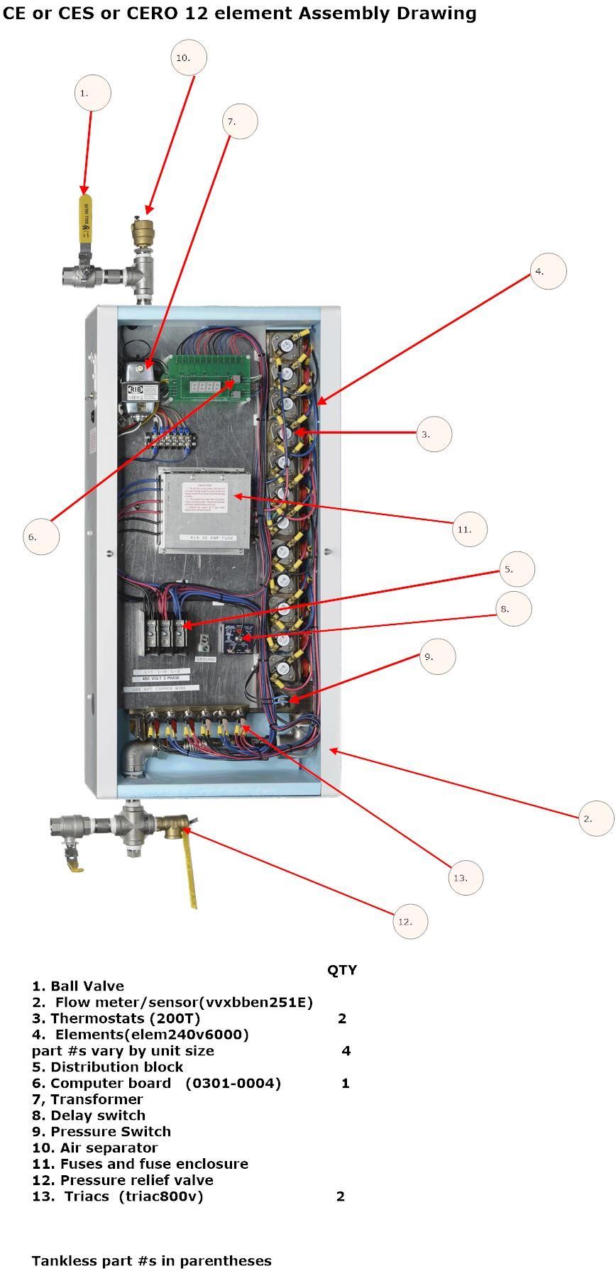
12 Trouble shooting for electricians CE and CES Series troubleshooting. Be sure you are a qualified electrician before proceeding. This series of units operates off a flow meter and computer board that turn the units elements on and off. The thermostats in this unit are solely a safety feature to shut the unit down in case of failure. Depending on how you are using your unit the thermostats could be 90 F or 200 F. These thermostats determine the MAXIMUM temperature inside the unit before they break the circuit. 1. Run fluid thru the unit and be sure any air is out of the unit. 2. Turn the unit on and watch the computer board. 3. If the computer board lights up and goes thru its diagnostic routine and shows your temperature setting when it is finished then the following parts are working properly..computer board..#6 in the picture below and pressure switch #9 in the picture below. If you have water pressure of over 3 PSI and the board does not light up then check the pressure switch for continuity across the two spade terminals with wire connections on them. If it has continuity and the board does not light up then you must replace the board. If it does not have continuity then you must replace the pressure switch. PROBLEMS THAT CAN OCCUR No heating of any water Solution 1. Verify that the computer board is on and reading the current temperature. If not then check the water pressure and power in for a bad connection or not enough pressure. 2. Take the pressure switch out of the equation by connecting temporaily the in and out to the pressure switch. If the unit comes on when you do this the pressure switch is the problem. 3. Verify there is no blockage in the water stream as mentioned in 3 above. 4. If the board does not come on then it is possible the board has failed. Call for a new one. Insufficient heating 1 A common problem with this unit at initial start up is a restricted flowmeter.see #2 in the picture below. This part is a vortex meter that measures the fluid thru it. If there is any restriction the flexible tube will have to be removed to enable a cleaning of the flow meter. 2 If the unit is heating but not producing what you need check to see if the board is flashing. If yes, it is telling you it is being asked to do more than it can. Back off the flow level till the board quits flashing. Then test the water output and compare it to the set point. If the output temperature is still lower than expected you probably have a bad element or a blown fuse. You will need to check continuity on all elements and fuses to determine which 12
13 parts have failed. The fuse is in the fuse enclosure between the triac and the element and is denoted on the picture on page 11, item #16. 3 If the unit is still not heating the fluid as well as you think it should then do the following test. Turn the flow on and the heat up till the board flashes at you like it says ther e is a full load on the unit. Using an AMP gauge test each of the three phases for Amperage. On the from panel of the unit the name plate shows the full load AMP draw for the unit. Compare that to the test you just did. If they are the same then the unit is doing all it can do and you need to slow the flow or lower the heat level. 4 If it is not pulling a full load document the draw on each line and compare it to the full load draw. The lines the have a lower Amp draw have a part that is not working and it is probably an element or a thermostat in that circuit. Too much heat 1. This generally occurs when a triac fails and does not properly shut off the electricity flow to the elements. In this case the thermostats sut the unit down but the customer will not be able to adjust the output temperature. Find the failed triac by shutting off the flow and do the AMP draw test above. At no flow there should be no AMP draw or minimal to light up the pilot lights. 2. Find the triac that is the problem by finding the element that is receiving AMP draw with an AMP gauge or by testing the triac with the power off for an ohms reading. They should all be in around.63 ohms when measured across the gate to the line. You will have continuity always across the power lines of the triac if the triac has failed. Please also refer to the tests following the drawing of the inside of the unit. 3. The following picture shows the inside of an electronic heater as a reference to the parts discussed. 13
14 14
15 If the unit is still not working do the following tests before proceeding. Turn off the main power. 1. Determine if the elements ohm to their correct reading : Ohms Test: Check each element(#4 in the above picture) with an OHMs meter for correct readings. If the elements reads 0 or flickers it is bad and needs to be replaced. If the failed element looks like it was split from the inside it probably failed due to air in the heater and you need to check the water source for a problem. 6KW 240 volts= 10 OHMS 6 KW 208 volts= 7.2 OHMS 6 KW 277 volts= 12.8 OHMS 5 KW 240 volts= 12.2 OHMS 4.5 KW 240 volts= 13 OHMS 4 KW 240, 6 KW 288 volts= 15 OHMS 3 KW 240 volts= 19.5 OHMS 2. Test the thermostats(#3 in the above picture). The thermostats have only a safety funtion in the CE series and generally only fail in an overheating situation. They shut the unit down if the temperature inside exceeds their setting. The thermostat can fail permanently if the water in the chamber overheats and if it goes over 260 degrees Fahrenheit the fuse side of the thermostat will burn and the thermostat will never work again. The thermostat will have continuity if the fuse side of the thermostat is still good. The thermostats condition is determined by a continuity check AFTER POWER IS OFF AND AFTER COLD WATER HAS BEEN RUN THRU THE HEATER TO RESET THE THERMOSTATS. Continuity is tested between the arms on the thermostat. Occasionally, you get a false positive on a thermostat. It may read as good but have a weak connection. If a thermostat tests as no continuity the thermostat should be replaced. 3. TEST the triacs. (#13 in the above picture) The triacs allow powerto pass thru them once the gate valve is opened by the computer board sending a signal thru the gate. This gate post is labeled #1 in the picture below and is smaller than the other two posts. Take an ohms reading across posts one(gate) and two(power out) of the triac as labeled in the picture below. It should read.63 ohms +/-. Then, check for continuity across posts two and three which are the outlet power and return power. Both these posts are larger than the gate post mentioned above. If you have continuity the triac has shorted and must be replaced with the 800 volt triacs specified by the factory. 15
16 TRIAC REPLACEMENT PROCEDURES 1. You need an allen wrench to loosen the screws that hold the trica to the plate. 2. Remove the three wires. 3. Put the white heat sync paste that came with the tric on the back of the triac. 4. Remove the old triac and replace it with the new one noting that the location of the gate stud that is smaller of the other two is in the same place as before. 5. Be sure the triac is secure to the plate and that some white heat sync paste has seeped out the side 6. Attach the wires as they were before. Fuses: The fuses are 35 AMP fuses for all 6000 watts at 240 volts and larger and 30 AMP fuses for the smaller size elements. A simple continuity test will tell you if they are intact. They are easily removed from the black case by unscrewing the fuse holder. Call us at for assistance if you have any questions. If the unit is still not putting out the temperature of fluid you expect you need to do the following tests. Set the temperature to a high enough temperature and flow level that the heater will need maximum draw to fulfill the task. Test for full load AMP draw with an AMP meter after referring to the engineering chart on page 4 that shows FLA by unit size and voltage.. Also at FLA, the computer board on the unit unit should be flashing which indicates you are asking the unit to do more than it can do. It will also flash the temperature of the water it thinks it is creating for 15 of every 60 seconds and then go back to flashing your requested temperature. Reduce the temperature requested till the unit quits flashing. When the unit just quits flashing it should be operating at close to full load and putting out the temperature you are asking for within 2-3 degrees. Check for full load draw again and and the temperature output. 16
17 Check the line voltage and be sure you are receiving the proper voltage across two of the three lines of your three phase heater. If the output temperature is not within 3 degrees you probably have an element that is not working or you have a computer board that is expecting more or less power going to the elements. Shut the unit off and do an ohms test on each element as shown in step 1 above. If all elements are good re do the continuity test on the thermostats. If they all have continuity they are good and are not the problem. If all the above checks out and you do not get the output you should then you should call us at for help or at any other time during this process. 17
Information Manual Rev 12.16F Installation and
 Model Number: Serial Number: Information Manual Rev 12.16F Installation and Troubleshooting Instructions for Electric Tankless Commercial Water Heaters CF SERIES ONLY CF 144 KW,CF 120 KW CF 108 KW, CF
INSTALLATION INSTRUCTIONS & HOME OWNERS MANUAL ECO 18 ECO 24 ECO 27 IMPORTANT SAFETY INFORMATION
 INSTALLATION INSTRUCTIONS & HOME OWNERS MANUAL ECO 18 ECO 24 ECO 27 IMPORTANT SAFETY INFORMATION As when installing or using any high voltage electrical appliance, basic safety precautions should always
HOMEADVANTAGE II IMPORTANT SAFETY INFORMATION
 INSTALLATION INSTRUCTIONS & HOME OWNERS MANUAL HOMEADVANTAGE II HA008240 HA011240 HA013240 HA018240 HA024240 HA027240 HA036240 IMPORTANT SAFETY INFORMATION When installing or using any high voltage electrical
PRO SERIES IMPORTANT SAFETY INFORMATION
 INSTALLATION INSTRUCTIONS & HOME OWNERS MANUAL PRO SERIES IMPORTANT SAFETY INFORMATION When installing or using any high voltage electrical appliance, basic safety precautions should always be followed.
SERVICE MANUAL. Bradford White ElectriFLEX HD (Heavy Duty) Commercial Electric Water Heater CEHD SERIES Immersion Thermostat Models
 Commercial Electric Water Heater CEHD SERIES Immersion Thermostat Models") Bradford White ElectriFLEX HD (Heavy Duty) Commercial Electric Water Heater CEHD SERIES Immersion Thermostat Models SERVICE MANUAL Troubleshooting Guide and Instructions for Service (To be performed ONLY
Bradford White ElectriFLEX HD (Heavy Duty) Commercial Electric Water Heater CEHD SERIES Immersion Thermostat Models SERVICE MANUAL Troubleshooting Guide and Instructions for Service (To be performed ONLY
INSTALLATION, OPERATION, AND MAINTENANCE MANUAL FOR THE HUBBELL MODEL JTX / JHX TANKLESS BOOSTER HEATER
 INSTALLATION, OPERATION, AND MAINTENANCE MANUAL FOR THE HUBBELL MODEL JTX / JHX TANKLESS BOOSTER HEATER ELECTRIC HEATER COMPANY * The Hubbell Model JTX is designed for use with conveyor and flight type
Tankless On Demand Electric Water Heater
 ECO FRIENDLY 98% EFFICIENT ENERGY & WATER SAVING Model MTX Tankless On Demand Electric Water Heater Available Up To 54 KW in Single or Three Phase Voltages Marine Approvals American Bureau of Shipping
Use & Care Manual. Electric Tankless Water Heaters. With Installation Instructions for the Installer AP15447 (10/10)
") Use & Care Manual With Installation Instructions for the Installer Electric Tankless Water Heaters The purpose of this manual is twofold: one, to provide the installer with the basic directions and recommendations
Use & Care Manual With Installation Instructions for the Installer Electric Tankless Water Heaters The purpose of this manual is twofold: one, to provide the installer with the basic directions and recommendations
Tankless Electric Water Heater Available up to 54 KW in Single or Three Phase Voltages
 Model HX/TX Tankless Tankless Electric Water Heater Available up to 54 KW in Single or Three Phase Voltages Features Heavy Duty Construction Constructed with high grade materials to ensure long operating
Low kw Electric Tankless Water Heater Troubleshooting Guide
 Technical Service Bulletin Low kw Electric Tankless Water Heater Troubleshooting Guide Models: AE3.4, AE7.2, AE9.5, RP1P, RP2P, RP3P, RP7P, RP9P, US3, US6, US7, US9 DANGER: ELECTRIC SHOCK ELECTRICITY IS
INSTALLATION, OPERATION, AND MAINTENANCE MANUAL FOR THE HUBBELL MODEL TX / HX TANKLESS WATER HEATER
 INSTALLATION, OPERATION, AND MAINTENANCE MANUAL FOR THE HUBBELL MODEL TX / HX TANKLESS WATER HEATER ELECTRIC HEATER COMPANY Edition 2012A HUBBELL ELECTRIC HEATER COMPANY P.O. BOX 288 STRATFORD, CT 06615-0288
INSTALLATION, OPERATION, AND MAINTENANCE MANUAL FOR THE HUBBELL MODEL JTX TANKLESS BOOSTER HEATER ELECTRIC HEATER COMPANY
 INSTALLATION, OPERATION, AND MAINTENANCE MANUAL FOR THE HUBBELL MODEL JTX TANKLESS BOOSTER HEATER ELECTRIC HEATER COMPANY Edition 2011 HUBBELL ELECTRIC HEATER COMPANY P.O. BOX 288 STRATFORD, CT 06615-0288
Dexter Commercial Vended Stack Washer Dryer. Dryer Troubleshooting, Fault Codes, And Schematics. Starting serial number (12/13)
") Dexter Commercial Vended Stack Washer Dryer Dryer Troubleshooting, Fault Codes, And Schematics Starting serial number 481983 8533-070-001 (12/13) Dryer Trouble Shooting Electronic Control Diagnostic Lights
Dexter Commercial Vended Stack Washer Dryer Dryer Troubleshooting, Fault Codes, And Schematics Starting serial number 481983 8533-070-001 (12/13) Dryer Trouble Shooting Electronic Control Diagnostic Lights
ECOSMART TROUBLE SHOOTING GUIDE MODELS ECO POU 3.5-6
 ECOSMART TROUBLE SHOOTING GUIDE MODELS ECO POU 3.5-6 THIS STEP BY STEP TROUBLE SHOOTING GUIDE IS DESIGNED FOR THE INSTALLER IF ANY ISSUES ARISE WITH TANKLESS WATER HEATER. Step by Step Trouble Shooting
Tankless Electric Water Heater Available 3-27 kw in Single Phase Voltages
 Point-of-Use Tankless Tankless Electric Water Heater Available 3-27 kw in Single Phase Voltages Features Heavy Duty Construction Reliability Constructed with high grade materials to ensure long operating
INSTALLATION INSTRUCTIONS AND OWNER S MANUAL FOR
 INSTALLATION INSTRUCTIONS AND OWNER S MANUAL FOR ELECTRIC ON-DEMAND TANKLESS WATER HEATERS: SpecAdvantage with PhD Technology SafeAdvantage with PhD Technology 208 and 480 VAC three phase 32 144 kw 600
INSTALLATION, OPERATION, AND MAINTENANCE MANUAL FOR THE HUBBELL TANKLESS WATER HEATER
 INSTALLATION, OPERATION, AND MAINTENANCE MANUAL FOR THE HUBBELL TANKLESS WATER HEATER ELECTRIC HEATER COMPANY Edition 2016A HUBBELL ELECTRIC HEATER COMPANY P.O. BOX 288 STRATFORD, CT 06615-0288 PHONE:
OPERATING AND MAINTENANCE MANUAL FOR PLATE HEAT EXCHANGER INDIRECT FIRED WATER HEATER. Electric Heater Company Base Model "BWXP"
 OPERATING AND MAINTENANCE MANUAL FOR PLATE HEAT EXCHANGER INDIRECT FIRED WATER HEATER Electric Heater Company Base Model "BWXP" HUBBELL ELECTRIC HEATER COMPANY P.O. BOX 288 STRATFORD, CT 06615 PHONE: (203)
OWNER S MANUAL Manufactured Home Downflow Gas Furnace: MGD-B Series
 OWNER S MANUAL Manufactured Home Downflow Gas Furnace: MGD-B Series Heat Controller, Inc. 1900 Wellworth Ave. Jackson, MI 49203 (517)787-2100 www.heatcontroller.com Owner s Manual MGD-B SERIES GAS FURNACE
Fred C. Gilbert Co. 106 Norris Road Bakersfield, Ca fax
 A R R O W P N E U M A T I C S Fred C. Gilbert Co. 106 Norris Road Bakersfield, Ca. 93308 661-399-9569 fax 661-393-9654 F I L T E R S R E G U L A T O R S L U B R I C A T O R S A C C E S S O R I E S H E
12 kw Electric Tankless Water Heater Troubleshooting Guide
 Technical Service Bulletin 12 kw Electric Tankless Water Heater Troubleshooting Guide Models: AE12, RP12T, US12 DANGER: ELECTRIC SHOCK ELECTRICITY IS EXTREMELY DANGEROUS. TAKE EXTRA PRECAUTIONS AND DISCONNECT
OPERATION & INSTALLATION MANUAL IR-30, IR-234, IR-245, IR-260, IR-288, IR-14K220, IR-18K220. Electric Tankless Hot Water Heater
 OPERATION & INSTALLATION MANUAL IR-30, IR-234, IR-245, IR-260, IR-288, IR-14K220, IR-18K220 Electric Tankless Hot Water Heater Table of Contents SAFETY INFORMATION... 1 INTRODUCTION... 2 Unit Operation...
TECHNICAL SERVICE DEPARTMENT Technical Service Bulletin Heat Pump Water Heater (Generation 4) Troubleshooting (Effective 1 Nov 2016)
 Troubleshooting (Effective 1 Nov 2016)") No Power,, Fan or Compressor Nothing happens at all. No compressor motor; no fan; no display. 1. See use and care manuals to turn unit ON and set operating MODE. 2. Check for the presence of power at the
No Power,, Fan or Compressor Nothing happens at all. No compressor motor; no fan; no display. 1. See use and care manuals to turn unit ON and set operating MODE. 2. Check for the presence of power at the
Service Handbook. Servicing should only be performed by a Qualified Service Agent.
 Service Handbook COMMERCIAL ELECTRIC WATER HEATERS Technical Support and Parts: 800-456-9805 www.americanwaterheater.com MODELS STCE3-52/80/119 & ITCE3-52/80/119 INSTALLATION CONSIDERATIONS - PRE SERVICE
Hot Surface Ignition (HSI) System Booklet
 System Booklet") Hot Surface Ignition (HSI) System Booklet American Dryer Corporation 88 Currant Road Fall River MA 02720-4781 Telephone: (508) 678-9000 / Fax: (508) 678-9447 E-mail: techsupport@amdry.com 010298MFM/abe
Hot Surface Ignition (HSI) System Booklet American Dryer Corporation 88 Currant Road Fall River MA 02720-4781 Telephone: (508) 678-9000 / Fax: (508) 678-9447 E-mail: techsupport@amdry.com 010298MFM/abe
EcoSmart Troubleshooting Guide
 EcoSmart Troubleshooting Guide Models POU 3.5 & 6 kw This guide is designed for installers or homeowners to help troubleshoot any issues experienced during the lifetime of the tankless water heater. For
Dexter Industrial On Premise Dryer. Troubleshooting, Fault Codes, And Schematics. Starting serial number Part # /13
 Dexter Industrial On Premise Dryer Troubleshooting, Fault Codes, And Schematics Starting serial number Dryer Trouble Shooting Symptom Probable Cause Suggested Remedy Tumbler does not turn Drive belts Check
Installation and Operation Guide
 Hot Water on Demand Installation and Operation Guide Thermo Boost Instant Water Heater Digital electric tankless instant water heater provides endless supply of hot water while significantly conserving
FURNACE OPERATION OVERVIEW
 You ve had a fun day but now it s getting chilly, so you decide to fire up the RV furnace. You flip the thermostat on, set the temperature and wait expectantly, but no heat comes from the outlets. It s
BK17 Heater. Read all instructions before using the heater. Contents
 Read all instructions before using the heater Contents 1) Components... 3 Total Assembly... 3 2) Specifications... 4 a) Power Specifications... 4 3) Receiving... 4 4) Safety... 5 a) Power connections...
INSTALLATION INSTRUCTIONS & HOME OWNERS MANUAL AUTOBOOSTER IMPORTANT SAFETY INFORMATION
 INSTALLATION INSTRUCTIONS & HOME OWNERS MANUAL AUTOBOOSTER IMPORTANT SAFETY INFORMATION When installing or using any high voltage electrical appliance, basic safety precautions should always be followed.
INSTALLATION INSTRUCTIONS AND OWNER S MANUAL
 INSTALLATION INSTRUCTIONS AND OWNER S MANUAL ELECTRIC INSTANTANEOUS WATER HEATERS WITH PhD 208 and 480 VAC three phase 32 144 kw 600 VAC three phase 130 / 150 kw BEFORE ATTEMPTING ANY INSTALLATION OR SERVICE
Rev B, 9/2/2009. Kodiak Chiller Overview
 930-0001 Rev B, 9/2/2009 Kodiak Chiller Overview Presentation Outline Phone: 781-933-7300 Lytron Technical Support Contact Information 3 Introduction 4 Part I: Unpacking 5 Part II: Installation 7 Part
Locally Controlled Bug Killers. Read all instructions before using the bug killer. Contents
 Read all instructions before using the bug killer Contents 1) Components... 3 Total Assembly... 3 2) Specifications... 4 a) BK10L... 5 b) BK15L... 5 c) BK20L... 5 3) Receiving... 5 4) Safety... 6 a) Power
Commercial Electric Energy Saver Water Heater IMMERSION AND SURFACE MOUNTED THERMOSTAT MODELS
 Energy Saver Commercial Electric Energy Saver Water Heater IMMERSION AND SURFACE MOUNTED THERMOSTAT MODELS SERVICE MANUAL Troubleshooting Guide and Instructions for Service (To be performed ONLY by qualified
Tempco s process controllers provide integrated solutions to manage your thermal loop system.
 5 Control Panels Managing 5 Circulation Heating Systems Application: Cleaning and applying chromate coating to aircraft parts Tempco s process controllers provide integrated solutions to manage your thermal
OPERATING AND MAINTENANCE MANUAL FOR ELECTRIC STAINLESS STEEL HEATER FOR DEIONIZED (DI) WATER ELECTRIC HEATER COMPANY BASE MODEL D
 WATER ELECTRIC HEATER COMPANY BASE MODEL D") OPERATING AND MAINTENANCE MANUAL FOR ELECTRIC STAINLESS STEEL HEATER FOR DEIONIZED (DI) WATER ELECTRIC HEATER COMPANY BASE MODEL D HUBBELL ELECTRIC HEATER COMPANY P.O. BOX 288 STRATFORD, CT 06615 PHONE:
OPERATING AND MAINTENANCE MANUAL FOR ELECTRIC STAINLESS STEEL HEATER FOR DEIONIZED (DI) WATER ELECTRIC HEATER COMPANY BASE MODEL D HUBBELL ELECTRIC HEATER COMPANY P.O. BOX 288 STRATFORD, CT 06615 PHONE:
CNA-Series - Large Industrial Heaters Tankless Water Heating Solutions
 36-144 kw (122,800-491,300 BTUs) Certified Lead-Free Design New & Improved Pressure Drop Advantage Variable Temp Heat Exchanger NEMA 4 enclosure standard Independent Safeties ETL and cetl certified to
Bug Killers. Read all instructions before using the bug killer. Contents
 Read all instructions before using the bug killer Contents 1) Components... 3 Total Assembly... 3 2) Specifications... 4 a) BK10... 5 b) BK15... 5 c) BK20... 5 3) Receiving... 5 4) Safety... 6 a) Power
INSTALLATION & MAINTENANCE MANUAL FOR QuickDraw
 INSTALLATION & MAINTENANCE MANUAL FOR QuickDraw SEMI-INSTANTANEOUS ENERGY: STEAM TO WATER U-TUBE SINGLE-WALL & DOUBLE-WALL HEAT EXCHANGERS FLOOR DRAIN Typical Construction Figure 34-1 FLOOR DRAIN 1. U-tube
C1N Series - Light Industrial Heaters Tankless Water Heating Solutions
 18-25 kw (61,4000-85,300 BTUs) Low flow activation options at 0.25 and 0.50 GPM (1.0 and 1.9 LPM) Certified Lead-Free Design Variable Temp Heat Exchanger Pressure Drop Advantage NEMA 4 enclosure standard
Wrangler JK Engine Cooling
 Wrangler JK Engine Cooling Preface In the old days the temperature gauge was a simple and direct monitor of engine cooling. Contemporary cars with their recovery tanks, electric fans, and electronic controls
User Guide. For THE SWIMSUIT DRYER. Swimsuit Dryer manual Final. Copyright 2014 Page of 20
 User Guide For THE SWIMSUIT DRYER. Swimsuit Dryer manual Final Copyright 2014 Page of 20 1 Table of Contents 1 LOCATION & INFORMATION DIAGRAMS... 4 2 PURPOSE... 6 2.1 PROPER USAGE AND LIABILITY... 6 2.2
Discontinued. SN Series - Safety Shower Heaters Tankless Water Heating Solutions. Standard Equipment. Construction. Code Compliance and Certifications
 36-144 kw (122,800-491,300 BTUs) Temperature overshoot purge system Certified Lead-Free Design NEMA 4 enclosure standard ASME and NB Certified options available Pressure Drop Advantage Dual Flow Activation
SMARTBOOST IMPORTANT SAFETY INFORMATION
 INSTALLATION INSTRUCTIONS & HOME OWNERS MANUAL SMARTBOOST IMPORTANT SAFETY INFORMATION When installing or using any high voltage electrical appliance, basic safety precautions should always be followed.
ELECTRIC WATER HEATER INSTALLATION & OPERATING INSTRUCTION MANUAL
 ELECTRIC WATER HEATER INSTALLATION & OPERATING INSTRUCTION MANUAL THE MANUFACTURER OF THIS HEATER WILL NOT BE LIABLE FOR ANY DAMAGE RESULTING FROM FAILURE TO COMPLY WITH THESE INSTRUCTIONS. READ THESE
Internet Version for Reference Only INDUCED DRAFT COMMERCIAL WATER HEATERS SUPPLEMENT INSTRUCTIONS TO PART #
 INDUCED DRAFT COMMERCIAL WATER HEATERS SUPPLEMENT INSTRUCTIONS TO PART #238-39387-00 THIS INSTRUCTION SUPPLEMENT IS ONLY INTENDED TO GIVE INSTALLATION INSTRUCTIONS AND INFORMATION RELATED TO THE INDUCED
INSTALLATION INSTRUCTIONS & HOME OWNERS MANUAL TANKBUDDY IMPORTANT SAFETY INFORMATION
 INSTALLATION INSTRUCTIONS & HOME OWNERS MANUAL TANKBUDDY IMPORTANT SAFETY INFORMATION When installing or using any high voltage electrical appliance, basic safety precautions should always be followed.
Single Phase Simplex SXL21=3, SXL24=3, SXH21=3, and SXH24=3
 Single Phase Simplex SXL21=3, SXL24=3, SXH21=3, and SXH24=3 Manufactured by SJE-Rhombus Installation Instructions and Operation/Troubleshooting Manual 7000 Apple Tree Avenue Bergen, New York 14416 Phone:
Columbia Boat Alarms, Inc.
 Columbia Boat Alarms, Inc. Model 411 Installation Manual http://www.columbiaboatalarms.com sales@columbiaboatalarms.com 4/4/2017 Forward Thank you for purchasing our Model 411 Columbia Boat Alarm! The
Tepid Water Delivery System
 Provides Tepid Water For Emergency Fixtures Features Heavy Duty Construction Hydrastone cement lining provides tank longevity Copper-silicon alloy tappings cannot rust or corrode High impact composite
Q - Series Boiler. Troubleshooting Manual
 Q - Series Boiler Troubleshooting Manual WARNING There are a number of live tests that are required when fault finding this product. Extreme care should be used at all times to avoid contact with energized
Norcold Repair Guide for Ice Maker
 Norcold Repair Guide for Ice Maker Section 10 Table of Contents Page: 10-2 General Description 10-2 Refrigerator Specifications 10-2 Refrigerator Operating Limits 10-2 Refrigerator Current Draws 10-2 Ice
MODEL A5-2 SOLVENT & WATER RECOVERY SYSTEMS (EXPLOSION PROOF UNITS)
") MODEL A5-2 SOLVENT & WATER RECOVERY SYSTEMS (EXPLOSION PROOF UNITS) FOR PROPER AND SAFE USE OF THIS CHEMCHAMP EQUIPMENT, PLEASE FOLLOW THIS DOCUMENT AND LOCAL AUTHORITY. KEEP THIS DOCUMENT FOR FUTURE REFERENCE.
MODEL A5-2 SOLVENT & WATER RECOVERY SYSTEMS (EXPLOSION PROOF UNITS) FOR PROPER AND SAFE USE OF THIS CHEMCHAMP EQUIPMENT, PLEASE FOLLOW THIS DOCUMENT AND LOCAL AUTHORITY. KEEP THIS DOCUMENT FOR FUTURE REFERENCE.
Keltech SNA-Series - Safety Shower Heaters Tankless Water Heating Solutions
 36-144 kw (122,800-491,300 BTUs) Temperature overshoot purge system Certified Lead-Free Design NEMA 4 enclosure standard ASME and NB Certified options available New & Improved Pressure Drop Advantage Dual
Electrical Problems. Fuse(s) blow or circuit breaker trips. Does the unit use circuit breakers or fuses? Replace with correct fuse(s)
 blow or circuit breaker trips. Does the unit use circuit breakers or fuses? Replace with correct fuse(s)") Electrical Problems Fuse(s) blow or circuit breaker trips Does the unit use circuit breakers or fuses? Fuse(s) Circuit breakers Are the fuses dual element time delay? Is the circuit breaker HACR rated?
Electrical Problems Fuse(s) blow or circuit breaker trips Does the unit use circuit breakers or fuses? Fuse(s) Circuit breakers Are the fuses dual element time delay? Is the circuit breaker HACR rated?
Burn Easy Installation Instructions LP or Natural Gas Fired Units. Cremator Setup:
 Burn Easy Installation Instructions LP or Natural Gas Fired Units Cremator Setup: 1. Place cremator, outdoor on a solid base consisting of concrete or gravel. Keep this site free of all vegetation. Combustibles
Tested and certified by the Water Quality Association against NSF/ANSI 372 for lead free compliance.
 INSTALLATION INSTRUCTIONS & HOME OWNERS MANUAL ECO 8 ECO 11 ECO 18 ECO 24 ECO 27 ECO 36 IMPORTANT SAFETY INFORMATION When installing or using any high voltage electrical appliance, basic safety precautions
Check that connection to main board is clean and sound at J8
 1 of 6 22/10/2012 3:15 PM. Home Products What's New Support MINI MAX DIGITAL SPA PAK rev: 04 USING CT250 Printed Circuit Board TROUBLE SHOOTING GUIDE No display at topside Check miss-wire fuse between
Congratulations! You've just purchased a new Marey ECO tankless water heater and will soon begin to enjoy the benefits of going tankless.
 Congratulations! You've just purchased a new Marey ECO tankless water heater and will soon begin to enjoy the benefits of going tankless. Please take the time to thoroughly read and understand this safety
DC50X2 Models 50 Pound Stacked Commercial Dryer. Troubleshooting,Fault Codes, and Schematics. Starting serial number Part # /13
 DC50X2 Models 50 Pound Stacked Commercial Dryer Troubleshooting,Fault Codes, and Schematics Starting serial number Trouble Shooting Electronic Control Diagnostic s The electronic control has 6 diagnostic
BK5 Bug Killer. Read all instructions before using the bug killer. Contents
 Read all instructions before using the bug killer Contents 1) Components... 3 Total Assembly... 3 2) Specifications... 4 3) Receiving... 4 4) Safety... 5 a) Power connections... 6 b) Control power... 6
SUPER HIGH EFFICIENCY WATER HEATERS SUPPLEMENT TO INSTRUCTION MANUAL P/N (Replaces pg. 2 in instruction manual.) CONGRATULATIONS!
 CONGRATULATIONS!") SUPER HIGH EFFICIENCY WATER HEATERS SUPPLEMENT TO INSTRUCTION MANUAL P/N 238-44219-00 (Replaces pg. 2 in instruction manual.) CONGRATULATIONS! You have just purchased one of the finest water heaters on
SUPER HIGH EFFICIENCY WATER HEATERS SUPPLEMENT TO INSTRUCTION MANUAL P/N 238-44219-00 (Replaces pg. 2 in instruction manual.) CONGRATULATIONS! You have just purchased one of the finest water heaters on
Installation and Operation Guide
 Hot Water on Demand Installation and Operation Guide Thermostatic Series 18kW, 21kW, 24kW 118 º F www.atmorusa.com Table of Contents Description Page Safety Guidelines...2 Technical Information...3 Plumbing...
Each heater has slightly different operational characteristics
 NOTE, YOU MAY WANT TO PRINT THIS GUIDE TO ASSIST YOU IN TROUBLE SHOOTING New information regarding the Ultra Low Sulfur Diesel Fuel Heater Trouble Shooting Guide Customer Name Phone Step 1. Basic Information
DHC-E TANKLESS ELECTRIC WATER HEATERS INSTALLATION INSTRUCTIONS FOR THE LICENSED PLUMBER AND ELECTRICIAN
 DHC-E 20, DHC-E 30 DHC-E TANKLESS ELECTRIC WATER HEATERS INSTALLATION INSTRUCTIONS FOR THE LICENSED PLUMBER AND ELECTRICIAN Table of contents Temperature increase above ambient water temperature.. 2 General
INSTALLATION AND OPERATION INSTRUCTIONS FOR BI-DEEP UNITS
 INSTALLATION AND OPERATION INSTRUCTIONS FOR BI-DEEP UNITS BI-40-DEEP BI-50-DEEP BI-60-DEEP BI-72-DEEP BI-88-DEEP SAFETY INFORMATION WARNING If the information in these instructions are not followed exactly,
MONITRON II MODEL EH-M2 ELECTRIC BOILER OPERATION AND INSTALLATION INSTRUCTIONS. Four stage electronic control with energy saving and other features.
 MONITRON II MODEL EH-M2 ELECTRIC BOILER Four stage electronic control with energy saving and other features. EH-08-135-M2 through EH-40-135-M2 3 wire 120/208V, 120/240V single phase EH-12-345-M2 through
Technical Manual. VFD / Cabinet Heater Upgrade 110 VAC Heater to 12 VDC Heater. Provided by: Chart Inc.
 Technical Manual VFD / Cabinet Heater Upgrade 110 VAC Heater to 12 VDC Heater Provided by: Chart Inc. 407 7th Street NW New Prague, MN 56071 USA (800) 400-4683 Part Number 20977233 Rev. A 2016 Chart Inc.
Model 8780 INSTALLATION, OPERATION & MAINTENANCE INSTRUCTIONS. Tempering Skid General Area Classification & Class I Division 2. No.
 INSTALLATION, OPERATION & MAINTENANCE INSTRUCTIONS 1455 Kleppe Lane Sparks, NV 89431-6467 (775) 359-4712 Fax (775) 359-7424 E-mail: haws@hawsco.com Website: www.hawsco.com Model 8780 Tempering Skid General
Circulating Oil Temperature Control System
 Installation & Operation Manual Circulating Oil Temperature Control System i PQ451 161-123417-037 February 2019 Table of Contents Contents Page Number Section 1 Getting Started... 1 Section 2 Installation...
OPERATION & INSTALLATION MANUAL
 OPERATION & INSTALLATION MANUAL Model: SIO 14 & SIO 18 Electric Tankless Hot Water Generators Table of Contents SAFETY INFORMATION... 1 INTRODUCTION... 2 Unit Operation:... 2 Unit Freezing:... 3 Maintenance:...
User s Manual. TIGER S EYE E-Series Mark V Jockey. TIGERFLOW Systems, Inc Mint Way Dallas, Texas
 User s Manual TIGER S EYE E-Series Mark V Jockey TIGERFLOW Systems, Inc. 4034 Mint Way Dallas, Texas 75237 214-337-8780 www.tigerflow.com TABLE OF CONTENTS Introduction... 4 Sequence of Operation... 5
AGP. (All Grade Pellet) Troubleshooting Guide Document Copyright 2017 Travis Industries Certified Factory Training Program
 Troubleshooting Guide Document Copyright 2017 Travis Industries Certified Factory Training Program") AGP (All Grade Pellet) Troubleshooting Guide Document 176-01795 Copyright 2017 Travis Industries Certified Factory Training Program The unit has been programmed to evacuate smoke in case of a power failure.
AGP (All Grade Pellet) Troubleshooting Guide Document 176-01795 Copyright 2017 Travis Industries Certified Factory Training Program The unit has been programmed to evacuate smoke in case of a power failure.
2 THERMOSTAT DETAILS 3 REMOVING OLD THERMOSTAT
 CONTENTS Installation Instructions for Heating & Air Conditioning 1F79 n-programmable Heat Pump Thermostat Preparations... 1 Thermostat Details... 1 Removing Old Thermostat... 1-2 Mounting and Wiring...
State problem and/or comments:
 Technical Service Ticket Date: Customer Name: Model: Voltage Supply: Amperage Draw per element: Dealer Name: Contact Number: Serial Number: Circuit Breaker Size: Physical Size of the Room: Purchase Date:
SNA-SKID Series - Preassembled Safety Shower Heater Skid Tankless Water Heating Solutions
 Pre-assembled skid system Back-to-Back heater models, SNA & SNAR High Flow Demand Safety Shower Applications 216-288 kw (737,000-983,000 BTUs) Temperature overshoot purge system NEMA 4 enclosure standard
ELECTRIC WATER HEATER HT382E55
 ELECTRIC WATER HEATER HT382E55 Note: Before operating or installing this electric water heater read this manual and follow all safety rules and operating instructions. 220v 240v 60Hz 30~55 C 6.8 Kw 1.8
IF79 CAUTION CONTENTS YOUR THERMOSTAT REPLACES 1 PREPARATIONS. Installation Instructions for. Heating & Air Conditioning
 CONTENTS Installation Instructions for Heating & Air Conditioning IF79 n- Programmable Heat Pump Thermostat Preparations... 1 Thermostat Details... 1 Removing Old Thermostat... 1-2 Mounting and Wiring...
Installation and Operation Guide
 Hot Water on Demand Installation and Operation Guide Thermo-Pro Thermostatic Series 18kW, 21kW, 24kW, 27kW 118 º F www.atmorusa.com Table of Contents Description Page Safety Guidelines...2 Technical Information...3
USER MANUAL WATER DISPENSER WITH ICE MAKER
 USER MANUAL WATER DISPENSER WITH ICE MAKER Model:048-GM-48200 Please read this owner s manual carefully before operating the unit. TABLE OF CONTENTS INTRODUCTIONS... 3 IMPORTANT SAFETY INSTRUCTIONS.. 3
PARTS AND SERVICE MANUAL FOR MERCO HOLDING CABINET MODEL 86002
 PARTS AND SERVICE MANUAL FOR MERCO HOLDING CABINET MODEL 86002 Merco Savory, Inc. 1111 North Hadley Road Fort Wayne, Indiana 46804 United States of America Phone: (260) 459-8200 U.S. Facsimile: (888) 790-8193
WATLOW IND. WATROD Modular Duct Heater Installation & Maintenance Manual I&M NUMBER: Page: 1 Date:6/11/2008 Rev: 2
 I&M NUMBER: 316-42-15-1 Page: 1 _ Pre Installation Check to make sure that heater received is the same as that ordered. Elements may come in contact with each other during shipment. Minor adjustments to
SUPER HIGH EFFICIENCY WATER HEATERS SUPPLEMENT TO INSTRUCTION MANUAL P/N (Replaces pg. 2 in instruction manual.) CONGRATULATIONS!
 CONGRATULATIONS!") SUPER HIGH EFFICIENCY WATER HEATERS SUPPLEMENT TO INSTRUCTION MANUAL P/N 238-51012-00 (Replaces pg. 2 in instruction manual.) CONGRATULATIONS! You have just purchased one of the finest w ater heaters on
SUPER HIGH EFFICIENCY WATER HEATERS SUPPLEMENT TO INSTRUCTION MANUAL P/N 238-51012-00 (Replaces pg. 2 in instruction manual.) CONGRATULATIONS! You have just purchased one of the finest w ater heaters on
New Power Vented Rheem FVIR Tanks
 Technical Bulletin B06-08 Sept 26/ 2006 New Power Vented Rheem FVIR Tanks In the coming weeks new power vented FVIR tanks will be arriving in the field from our tank manufactures. We are supplying some
be liable for any other loss or damage, whether direct, indirect, incidental or consequential.
 Integrated HydroStat 3200-Plus for Slant Fin Boilers Part No. 48-3200-03 and 48-3200-04 120 VAC Input / 24 VAC Burner Circuit PATENT S. 8.391,708; 7,891,572; 8,844,834; Others Pending INSTALLATION INSTRUCTIONS
MERCHANT POPCORN MACHINE SERVICE MANUAL
 3243 North California Avenue, Chicago, IL 60618 MERCHANT POPCORN MACHINE SERVICE MANUAL 120 Volt, Single Phase, 60 Hz 230 Volt, Single Phase, 50 Hz READ and UNDERSTAND this servicing, and safety instructions
Operator: Save these instructions for future use!
 50V64-743 Integrated Furnace Control for Furnaces with Variable Fan Speed INSTALLATION INSTRUCTIONS Operator: Save these instructions for future use FAILURE TO READ AND FOLLOW ALL INSTRUCTIONS CAREFULLY
OPERATING & SERVICE PARTS MANUAL HDS-215 COMBINATION SHRINK SYSTEM
 OPERATING & SERVICE PARTS MANUAL HDS-215 COMBINATION SHRINK SYSTEM FOR HOT KNIFE AND IMPULSE MACHINES READ ALL INSTRUCTIONS CAREFULLY BEFORE OPERATING EQUIPMENT TABLE OF CONTENTS Electrical Requirements
Packaged Instantaneous Circulation Heater Full KW Selection In All Voltages, Single or Three Phase
 Features Heavy Duty Construction Constructed with high grade materials to ensure long operating life Turn-Key package is simple to specify and operate Factory wired electrical controls provide trouble-free
INSTALLATION INSTRUCTIONS and OPERATING MANUAL. *Aquastat is a registered trademark of Honeywell International, Inc.
 MODEL 3200-Plus Temp Limit / LWCO Control with Thermal Targeting for Water Boilers 120 VAC Input / 24 VAC Burner Circuit PATENT. 8,931,708; 8,844,834; 7,891,572; others pending INSTALLATION INSTRUCTIONS
SEISCO SUPERCHARGER EXTENDER/BOOSTER INSTALLATION GUIDE & OWNERS MANUAL
 SEISCO SUPERCHARGER EXTENDER/BOOSTER INSTALLATION GUIDE & OWNERS MANUAL This manual is provided as a guide to installation. All installations must comply with any and all local and national electrical
GasScanner 8C. Eight Channel Monitor. Operator s Manual. MINT-0281-XX Rev. A 01/29/08
 GasScanner 8C Eight Channel Monitor Operator s Manual MINT-0281-XX Rev. A 01/29/08 Product Warranty Matheson Tri-Gas, Inc., warrants gas alarm equipment sold by us to be free from defects in materials,
CONTENTS CONSIDERATIONS. General Plumbing Component Connection ILLUSTRATION. Control System CONFIGURATION. Voltage Verification CONNECTION
 AIR SERIES SYSTEM INSTALLATION MANUAL CONTENTS CONSIDERATIONS General Plumbing Component Connection 2 2 2 ILLUSTRATION Control System 3 CONFIGURATION Voltage Verification 4 CONNECTION Component Connection
SN Series - Safety Shower Heaters Tankless Water Heating Solutions
 36-144 kw (122,800-491,300 BTUs) Temperature overshoot purge system Lead-Free Design NEMA 4 enclosure standard ETL and cetl certified to UL and CSA Standards Liquid-Cooled Solid State Relays Internal fusing
Technical Manual. Model: GSWH-2. Operation Functional Tests Troubleshooting Service and Maintenance
 Technical Manual Model: GSWH-2 Features: Demand Tankless Water Heater LP Gas / Induced Draft Constant Outlet Temperature Linear Gas Control Valve Electronic Gas Modulation Microprocessor Controls Operation
Portable Dryer Touch Screen Controls
 Portable Dryer Touch Screen Controls and Reference Manual PNEG 1509 PNEG 1509 Date: 1 23 08 Reference Table of Contents TABLE OF CONTENTS DRYER SAFETY & DRYER INFORMATION...4 SPECIAL SETUP SCREENS...5
Installation and Maintenance Manual Please retain this manual for future reference.
 342 N. Co. Rd. 400 East Valparaiso, IN 46383 219-464-8818 Fax 219-462-7985 www.heatwagon.com Installation and Maintenance Manual Please retain this manual for future reference. Electric Construction Heaters
Service Manual Model 3163
 Service Manual Model 3163 Contents Important Safety Information.......... 1 Specifications.................. 2 General Information.............. 2 Direct Vent Requirements........... 2 Propane System................
INSTALLATION INSTRUCTIONS and OPERATING MANUAL. *Aquastat is a registered trademark of Honeywell International, Inc.
 MODEL 3200-Plus Temp Limit / LWCO Control with Thermal Targeting for Water Boilers 120 VAC Input / 24 VAC Burner Circuit PATENT. 8,931,708; 8,844,834; 7,891,572; others pending INSTALLATION INSTRUCTIONS