Information Manual Rev 12.16F Installation and
|
|
|
- Susanna Bishop
- 5 years ago
- Views:
Transcription


1 Model Number: Serial Number: Information Manual Rev 12.16F Installation and Troubleshooting Instructions for Electric Tankless Commercial Water Heaters CF SERIES ONLY CF 144 KW,CF 120 KW CF 108 KW, CF 90 KW, or CF 81 KW CF 48 KW, CF 54 KW, or CF 72 KW CF 24 KW, CF 27 KW, or CF 36 KW CF 12 KW, CF 15 KW, CF 18 KW FOR MORE DETAILED SCHEMATICS AND WIRING DIAGRAMS VISIT, HOTWATERHEATER.COM 2060 B Whitfield Park Avenue * Sarasota, Florida * * tanklessinc@stiebel-eltron-usa.com 1
2 Table of Contents INFORMATION MANUAL for Commercial Heaters CF 12 KW, CF 15 KW, CF 18 KW, CF 24 KW, CF 27 KW, CF 36 KW, CF 48 KW, CF 54 KW, CF 60 KW, CF 72 KW, CF 81 KW, CF 90 KW, CF 108 KW,CF120 KW, CF 144 KW PAGE # How a CF Series Heater Works 3 Engineering Information and Breaker Sizes 4 Recovery Capacities Chart 5 CF Series Installation Instructions 6-7 Bill of Materials and Assembly drawings discussion 8 CF 12 KW, CF15 KW, CF 18 KW 9 CF 24 KW,CF 27 KW,CF 36 KW 10 CF 48 KW,CF 54 KW, CF 60 KW CF 72 KW 11 C 81KW, C 90 KW, C 108 KW 12 CF 120 KW,CF 144 KW Troubleshooting CF Series Parts replacement procedures Wiring diagram 12,15,18 KW 208 volt only 22 Wiring Diagram 18,24,27, volt only 23 Wiring diagram 48, 54, volt only 24 Wiring diagram 81, 90, volt only 25 Wiring diagram 120, volt only 26 Cut sheets 3 element, 6 element, 12 element, 18 element 24 element
3 How a CF Series Heater Works: We have four lines of heaters; electromechanical (CF series), electronic (CE series) electronic caustic fluids (CERO),and Restaurant Boosters (CR). They both heat the fluid as it passes thru but they are controlled in different manners depending on the customer s needs. This manual covers the CF models only. CF models: When a hot water tap is opened, the cold water entering the heater passes thru the first heat chamber from right to left over the first thermostat, the thermostat closes turning on the first electrical heat coil, and the coil heats the water as it passes directly over it. Depending on the size of the heater there are three, six, twelve, eighteen or twenty four thermostats and elements. Once the water reaches the temperature setting on the thermostat the thermostat does not close and that corresponding element and all later elements do not turn on. The heat exchanger maintains hot water as a type of mini boiler at all times. The amount of energy needed is in direct proportion to the volume of hot water flow being used, thereby using only the energy needed. When the hot water is turned off, the flow of energy turns off as well. Your hot water tap is an ignition key for energy used to heat all the hot water you need. The following charts show the full load AMP draw and physical size for each of our units (engineering chart) and the capabilities of each unit(recovery chart) in terms of temperature rise at a certain flow rate. 3
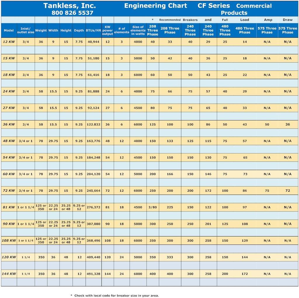
4 . 4

5 /16/2016
6 Installation Instructions CF Series heaters 1. Double check to be sure you ordered and we supplied the correct voltage unit. The voltage on our unit is listed on the label on the front cover. 2. All units have cold in the bottom and hot out the top. 3. Be sure to use a large enough breaker per the National Electric Code and large enough wire to meet code. Installation by a licensed electrician will insure this happens. 4. Our smaller units mount to the wall and the larger ones can be floor mounted. For the units in sizes from 12 KW thru 72 KW without a NEMA 4 enclosure use the provided brackets to mount the unit to the wall. For the 81KW thru 108 Kw without a NEMA 4 enclosure the brackets mounted to the side of the unit are used to mount the unit to the wall. 5. For the NEMA 4 enclosures use the feet provided to mount the heater to a wall or floor mount the unit using the C channel on the bottom of the enclosure. 6. For all units using 185 thermostats or below we provide a pressure relief valve that should be plumbed to a drain. 7. After the unit is properly plumbed in turn on the water flow and check for leaks. 8. Turn the delay switch to 1 which means the unit will turn on one minute after the control circuit is satisfied. 9. While flowing water thru the unit turn on the breaker and heater switch. 10. The circuit control light on the outside of the unit will light when the pressure switch and flow switch and timer have been satisfied. 11. Run a high volume of water thru the unit and check for AMP draw. Compare the AMP draw you get with the label on the unit. If you are not getting a full load AMP draw you will need to check each of the elements to see if you have a burned fuse or element. 12. The unit is now operational. 6
7 Bill of materials and Assembly drawings CF series.electromechanical heater models CF-12, CF-15, CF-18, CF 24, CF- 27, CF-36, CF-48, CF-54, CF-60 KW, CF-72, CF-81, CF-90,CF-108, CF 120 KW, CF 144 KW These instructions are only for qualified electricians. There are three main working parts in these heaters.elements, thermostats, and contactor. There also is a safety mechanism called a pressure switch(#9 on the picture below) and delay switch (#8 below) that will delay the heater turn on if there has been a water pressure loss. This delay switch is there to delay turn on of the heater up to eight minutes(actual delay depends on the setting) after a pressure drop to less than 3 PSI. If the heater is not turning on at all check the pressure switch for impediments.dirt or whatever and replace the pressure switch. All heaters have basically the same parts and the larger units just have more and larger elements. The pictures are shown with 480 voltage units only as they are most common. There is also an optional flow switch which only allows the unit to come on if there is water flowing into the unit. 7

8 The picture below shows our CF 36 unit in a non NEMA 4 box and is also applicable for the 24 KW, 27 KW, and 36 KW units. This picture is of a 480 volt unit. 8

9 The next assembly drawing is of the CF 48 KW unit and it is also applicable for the CF 54 KW and CF 72 KW units except the element part numbers change. For the 72 KW the element part number is 6KW240Velem. For the 54 KW model the elementpart number is 6KW277Velem. 9
10 The next assembly drawing is for the CF 108 KW unit and it is applicable to that unit as well as the CF 90 KW and CF 81 KW units. For the 81 KW the element part number is 6KW277Velem. For the 90 KW model the elementpart number is 5KW240Velem. 10

11 The picture below shows the assembly drawing for the CF 144 KW unit in a NEMA 4 enclosure. 11
12 Troubleshooting You will need the following items to test the units: continuity tester, Voltage meter, Amp meter, and Ohms meter. The optional lights on the sides of the units are to show which elements are engaged. If you have a NEMA 4 unit you have only a pilot light outside and the contactors will indicate their engagement or lack therof by the buttons on the contactor pulling in or not. You will have to open the door to observe the units operation. The thermostats activate the elements. With normal operation at maximum flow or when you first turn on the switch all lights will be on. the contactor buttons pulled in as long as there is water pressure coming to the unit. The lights and buttons will go on or off in series as the elements are engaged. The heater is designed to only use the thermostats and elements necessary to heat the water needed at any given time. Fluctuation in temperature can often be remedied by a simple adjustment of the outflow valve on the left side of the heater or it can be a more serious problem. Fluctation in hot water, lukewarm water, or no hot water at all, are almost always signs that indicate element, contactor or thermostat failure. Note: Where the heater fails to maintain the desired temperature you may be running the water faster than the heater is capable of heating the water. Use the following steps to diagnose a problem. Step 1: Turn off all power supply CAUTION FAILURE TO TURN OFF ALL POWER COULD RESULT IN SERIOUS INJURY OR DEATH FROM ELECTROCUTION. Step 2: Check for any loose connections, properly operating breakers, etc. Step 3: Turn off the switch to the heater. Step 4: Turn the delay switch all the way to the left..0. Step 5: Purge the heater. Run water thru the heater to cool it down. This will reset the thermostats. Step 6: Turn the water flow on. Turn the main breaker back on. Turn on the heater switch. Check to see if the contactor pulls in. When you first turn on the switch the contactor should pull in. That indicates the pressure switch and optional flow switch requirements have been met for theunit to turn on. If that is the case then proceed to step 8. If the contactor does not pull in.the buttons do not pull in on the contactor do the continuity test as shown in step 7. Step 7: Testing the flow switch and pressure switch. Turn off the power supply at the main breaker and the switch to the heater. CAUTION FAILURE TO TURN OFF ALL POWER COULD RESULT IN SERIOUS INJURY OR DEATH FROM ELECTROCUTION. Check for continuity across the pressure switch. If it is there the switch is closed and allowing electricity to flow thru the circuit. It it is not closed the switch could be plugged with impediment. More than likely thewater pressure is not high enough to close the switchwhich requires 3 psi. 12
13 /16/2016 With water flowing thru the unit check the continuity across the poles of the flow switch if you purchased this option. The flow must be 2-3 gallons per minute to close this switch and allow electricity to flow thru the switch. Step 8 Checking continuity of thermostats The thermostats have two funtions: one to regulate the turn on and off side of the units and to act as a safety in case of overheating. The thermostat can fail if a large amount of air goes into the unit and there is no flow switch and the elements overheat the water that is there to over 260 degrees. At that point the fuse side of the thermostat will burn and the thermostat will never work again. The thermostat will have continuity if the fuse side of the thermostat is still good. The thermostats condition is determined by a continuity check AFTER POWER IS OFF AND AFTER COLD WATER HAS BEEN RUN THRU THE HEATER TO RESET THE THERMOSTATS. Continuity is tested between the arms on the thermostat. Occasionally, you get a false positive on a thermostat. It may read as good but have a weak connection. If a thermostat tests as no continuity the thermostat should be replaced and the technician should determine what else could have caused the thermostat to fail. It is possible for the operator to shut off the cold water supply to the heater and blow all the thermostats but that is an abnormal occurrence. The unit has a pressure switch to shut the heater down in that case but there is no 100% protection against air entering the unit on its restart. Step 9: Ohms Test on Elements : If the contactor is pulling in and you still have bad performance(not hot enough, fluctations) you may have a failed element. Check each element with an OHMs meter for correct readings. If the elements reads 0 or flickers it is bad and needs to be replaced. If the failed element looks like it was split from the inside it probably failed due to air in the heater and you need to check the water source for a problem. 6KW 240 volts= 10 OHMS 6 KW 208 volts= 7.2 OHMS 5.3 KW 208 volts= 8.2 OHMS 5 KW 240 volts= 12.2 OHMS 4.5 KW 240 voltsor 6 KW at 277 volts = 13 OHMS 4 KW 240 volts or 6 KW at 288 volts= 15 OHMS 3 KW 240 volts= 19.5 OHMS Step 10: Testing the fuses If you have a failed element it is possible that you have a failed fuse so you must check the fuse to the element for continuity. 1. Remove the fuse from the holder and check for continuity. 2. The optional thermostat lights will tell you if the element is working. 3. If you need to replace the fuse be sure and use the correct size based on the AMP draw of the element. Step 11: Checking for leaks
14 If you have a leak there are four possible reasons 1. A plumbing leak that can be fixed at the site. Pipes not tight or valve not tight. 2. The o ring on the element failed. 3. The o ring on the thermostat failed. 4. Other leaks from the exchanger which is a more serious problem that will probably require a factory repair. This an extremely unlikely situation. Turn off the main power. Take paper towel and dry off the heater. Take another paper towel to find the leak source.either around the element or the thermostat. If the leak is at the element or thermostat; then 1. Drain all water from the heater 2. Take the element out and examine it for damage and test it for OHMS see step 8 3. Test the thermostat for continuity. 4. Order a new element or thermostat 5. Put in a new o ring if neither part failed but there is a leak at the part. You should have some in your spare parts kit. If you install a new element o ring be sure to not over tighten the element on reinstall. If neither of these is the entire problem the unit will have to be sent back to the factory. Parts replacement procedures. Procedures are shown for the main wear items in the unit. Before doing any parts replacement do the following. 1. Be sure power is off to the heater by checking the separate disconnect provided for this unit. 2. Shut off water flow to the unit from the inbound side. 3. Drain water from the unit by either opening the plug on the left bottom of the unit or opening a usage spigot in you system to relieve the water pressure inside the unit. Element replacement. 1. Remove the top cover to the unit. 2. Using a phillips screwdriver remove the wires from the element that tested as needing replacement. 3. Using a 1 ½ scoket wrench remove the element. The element is seated with a right hand thread. 4. Insert the new element being sure the element has the O ring with it the factory provided. 5. Tighten the element down with the wrench SNUG. Do not over tighten or you will ruin the o ring. 6. After all elements are replaced andbefore doing any wire replacement run water thru the heater to be sure the elements aresealed and tighten if necessary. 14
15 7. Reattach the wires to the elements. Thermostat replacement 1. Be sure the water is drained from the unit before starting as indicated above. 2. Remove the wires to the thermostat with a flathead scredriver 3. Remove the allen screws that hold the clips down with a ¼ allen wrench. A T handle wrench is recommended. 4. Remove the thermostatand replace it with the new one being sure the new one is the exact same item a 125T puts out 125 F water and a 185 T puts out 185 F water. Do not mix them up. 5. Replace the thermostat slips being sure they are concave down so they create a tight seal. The underside has a sharp edge to it be sure the sharp edge is down. Also be sure you use the factory provided o ring on the thermostatto provide a seal. 6. Reinsert the allen screws 7. Reattach the wires being sure to tighten them but do not over tighten them or you will break the thermostat at the tab. Contactor replacement procedures 1. Be sure the power to the unit is off. 2. Remove the element and thermostat wires. 3. Removethe mounting screws on the side of the contactor. 4. Replace the contactor with the new one being sure the part number matches exactly. The part number is made up of four parts. a. Prefix=MC b. Motor load AMP rating which is approximately 150 % of full load AMP draw in a resitance heater. A 100a would be the equivalent of a 150 full load AMP draw in a resistance heater. c. 120AC = coil voltage. If you have 480 or 575 the coil voltage is 120. If you have 208 the coil voltage is 208. If you have 240 voltage the coil voltage is 240. You MUST know your voltage before installing a new part and you must be sure you did not buy the wrong voltage unit. d. Suffix 2 or Rewire the element and thermostat wires exactly like they were and refer to the matching contactors in other positions of the wiring diagram provided with this manual. Transformer replacement would be necessary in the unlikely occurrence of the contactor chattering after you verified the power to the unit is a true 480 and you do not have voltage variance. 1. Be sure he power is off. 2. Check for continuity on the fuse FLM1-1/4 to be sure the problem is not just a fuse. 3. Replace the fuse if necessary. 4. Remove power wires from distribution block on lines 1 & 3 to the transformer. 5. Remove wire from transformer to the delay switch. 6. Remove old transformer from the plate by detcahing the screws at the cornerr of the transformer. 15
16 7. Replace with new transformer and rewire as before. 8. Double check to be sure the fuse on the transformer has continuity. Vent valve replacement and operation.. 5F6M3 1. This valve vents off air if air is in the water lines. 2. If replacement is needed do the following 3. Be sure power to the unit is off. 4. Shut off the inbound water source to the unit 5. Drain waterfrom the unit 6. Remove and replace the valve with a crescent wrench. Pressure switch replacement /16/ The pressure switch could become blocked with trashand not allow the unit to come on. 2. Check for continuity across the poles of the switch with water pressure to the unit and the power off. 3. If you have continuity the pressure switch is not the problem. 4. To remove and replace the switch do the following 5. Be sure the power to the unit is off 6. Drain water from the unit 7. Remove wires from the switch 8. Remove and replace the switch using an open end wrench 9. Check for water leaks 10. Rewire the switch. Pressure relief valve replacement 1. Sometimes these valves age and stick closed. 2. To replace shut off the power to the unit. 3. Drain water from unit 4. Remove and replace the valve with a wrench 5. Run water thru the heater 6. Check for leaks. 7. Open aluninum lever on the valve to be sue the valveworks as expected Delay switch replacement 1. Be sure power is off. 2. Remove the wire from the transformer to the input on theswitch and the one from line on the switch to the on/off switch and mark the wires. 3. Remove the old switch from the plate and replace it with the new one. 4. Rewire as before. 5. Set delay to 1 which means 1 minute. 16
17 Ball valve replacement 1. Be sure power to unit is off. 2. Shut off flow of water to the unit and drain the unit 3. Cut plumbing line before or after the unit to allow removal of the valve. 4. Install the valve and replumb. 5. Check for leaks and fix Indicator light replacement 1. If all circuits are working and the lights do not come on then the light is the problem. 2. Be sure power to the unit is off. 3. Clip the wires to the light 4. Remove the light..it simply pops out of the hole 5. Install the new light 6. Rewire the new light as before to the two leads you just cut. Toggle switch 452 BU 1. Be sure the power to the unit is off. 2. Remove the wires to the pressure switch and the delay switch 3. Remove the old switch by removing the nut that holds it in place 4. Install new switch 5. Reattach the wires Terminal block Be sure the power to the unit is off 2. Remove the wires from lines 1,2, and 3. Please note they are color coded. 3. Remove theold block and replace it with the new one 4. Reattach the wires. 5. Double check that the wires are tight. Fuses MDL 35 and KLK Be sure the power to the unit is off. 2. Remove the fuse from the fuse holder. 3. Replace the fuse with a properly rated fuse. For elements larger than or equal to the 6000 W at 240 Volt element use the 35 AMP fuse MDL 35 and for the smaller elements use part number???????????? 17
18 CF -15 KW wiring diagram The smaller units are shown in 208 Volt configurations. All wiring diagrams are available either online or by calling the company to have them send you a pdf of the drawing. 18
19 CF 36 KW 480 wirediagram you a pdf of the drawing. All wiring diagrams are available either online or by calling the company to have them send CF 72 KW 480 V wiring diagram All wiring diagrams are available either online or by calling the company to have them send you a pdf of the drawing. 19
20 CF 108 KW 480 volt wiring diagram diagram All wiring diagrams are available either online or by calling the company to have them send you a pdf of the drawing. 20
21 /16/2016
22 CF 144 KW 480 Volt wiring diagram All wiring diagrams are available either online or by calling the company to have them send you a pdf of the drawing 22
23 CUT SHEETS..CF Series units All cut sheets are also available on line at hotwaterheater.com. 23
24 All cut sheets are also available on line at hotwaterheater.com. 24
25 All cut sheets are also available on line at hotwaterheater.com. 25
26 All cut sheets are also available on line at hotwaterheater.com. 26
27 All cut sheets are also available on line at hotwaterheater.com. 27
Installation and Troubleshooting Instructions for Electric Tankless Commercial Water Heaters CE 12 KW, CE 15 KW, CE 18 KW CE 24 KW CE 27 KW CE 48 KW
 Model Number: Serial Number: Information Manual Rev # 03.24.17 Installation and Troubleshooting Instructions for Electric Tankless Commercial Water Heaters CE 12 KW, CE 15 KW, CE 18 KW CE 24 KW CE 27 KW
SERVICE MANUAL. Bradford White ElectriFLEX HD (Heavy Duty) Commercial Electric Water Heater CEHD SERIES Immersion Thermostat Models
 Commercial Electric Water Heater CEHD SERIES Immersion Thermostat Models") Bradford White ElectriFLEX HD (Heavy Duty) Commercial Electric Water Heater CEHD SERIES Immersion Thermostat Models SERVICE MANUAL Troubleshooting Guide and Instructions for Service (To be performed ONLY
Bradford White ElectriFLEX HD (Heavy Duty) Commercial Electric Water Heater CEHD SERIES Immersion Thermostat Models SERVICE MANUAL Troubleshooting Guide and Instructions for Service (To be performed ONLY
Low kw Electric Tankless Water Heater Troubleshooting Guide
 Technical Service Bulletin Low kw Electric Tankless Water Heater Troubleshooting Guide Models: AE3.4, AE7.2, AE9.5, RP1P, RP2P, RP3P, RP7P, RP9P, US3, US6, US7, US9 DANGER: ELECTRIC SHOCK ELECTRICITY IS
American Dish Service
 American Dish Service INSTALLATION INSTRUCTIONS Model JDS12 (T) or (R) Muffler Booster (T) 12kW, 240v, 3-ph, (R) 12kW, 208v, 3-ph Manufactured by Hubbell Electric Heater Company for use on American Dish
OPERATING AND MAINTENANCE MANUAL FOR ELECTRIC STAINLESS STEEL HEATER FOR DEIONIZED (DI) WATER ELECTRIC HEATER COMPANY BASE MODEL D
 WATER ELECTRIC HEATER COMPANY BASE MODEL D") OPERATING AND MAINTENANCE MANUAL FOR ELECTRIC STAINLESS STEEL HEATER FOR DEIONIZED (DI) WATER ELECTRIC HEATER COMPANY BASE MODEL D HUBBELL ELECTRIC HEATER COMPANY P.O. BOX 288 STRATFORD, CT 06615 PHONE:
OPERATING AND MAINTENANCE MANUAL FOR ELECTRIC STAINLESS STEEL HEATER FOR DEIONIZED (DI) WATER ELECTRIC HEATER COMPANY BASE MODEL D HUBBELL ELECTRIC HEATER COMPANY P.O. BOX 288 STRATFORD, CT 06615 PHONE:
OPERATING AND MAINTENANCE MANUAL FOR PLATE HEAT EXCHANGER INDIRECT FIRED WATER HEATER. Electric Heater Company Base Model "BWXP"
 OPERATING AND MAINTENANCE MANUAL FOR PLATE HEAT EXCHANGER INDIRECT FIRED WATER HEATER Electric Heater Company Base Model "BWXP" HUBBELL ELECTRIC HEATER COMPANY P.O. BOX 288 STRATFORD, CT 06615 PHONE: (203)
Commercial Electric Energy Saver Water Heater IMMERSION AND SURFACE MOUNTED THERMOSTAT MODELS
 Energy Saver Commercial Electric Energy Saver Water Heater IMMERSION AND SURFACE MOUNTED THERMOSTAT MODELS SERVICE MANUAL Troubleshooting Guide and Instructions for Service (To be performed ONLY by qualified
HOMEADVANTAGE II IMPORTANT SAFETY INFORMATION
 INSTALLATION INSTRUCTIONS & HOME OWNERS MANUAL HOMEADVANTAGE II HA008240 HA011240 HA013240 HA018240 HA024240 HA027240 HA036240 IMPORTANT SAFETY INFORMATION When installing or using any high voltage electrical
12 kw Electric Tankless Water Heater Troubleshooting Guide
 Technical Service Bulletin 12 kw Electric Tankless Water Heater Troubleshooting Guide Models: AE12, RP12T, US12 DANGER: ELECTRIC SHOCK ELECTRICITY IS EXTREMELY DANGEROUS. TAKE EXTRA PRECAUTIONS AND DISCONNECT
PRO SERIES IMPORTANT SAFETY INFORMATION
 INSTALLATION INSTRUCTIONS & HOME OWNERS MANUAL PRO SERIES IMPORTANT SAFETY INFORMATION When installing or using any high voltage electrical appliance, basic safety precautions should always be followed.
INSTALLATION INSTRUCTIONS & HOME OWNERS MANUAL ECO 18 ECO 24 ECO 27 IMPORTANT SAFETY INFORMATION
 INSTALLATION INSTRUCTIONS & HOME OWNERS MANUAL ECO 18 ECO 24 ECO 27 IMPORTANT SAFETY INFORMATION As when installing or using any high voltage electrical appliance, basic safety precautions should always
BK17 Heater. Read all instructions before using the heater. Contents
 Read all instructions before using the heater Contents 1) Components... 3 Total Assembly... 3 2) Specifications... 4 a) Power Specifications... 4 3) Receiving... 4 4) Safety... 5 a) Power connections...
Elite Primer Baldor Series External Pond Pump
 Elite Primer Baldor Series External Pond Pump ( 5250PPB21, 6440PPB23, 7550PPB26, 9600PPB28) Installation and User s Guide IMPORTANT SAFETY INSTRUCTIONS, READ AND FOLLOW ALL INSTRUCTIONS. SAVE THESE INSTRUCTIONS
Single Phase Simplex SXL21=3, SXL24=3, SXH21=3, and SXH24=3
 Single Phase Simplex SXL21=3, SXL24=3, SXH21=3, and SXH24=3 Manufactured by SJE-Rhombus Installation Instructions and Operation/Troubleshooting Manual 7000 Apple Tree Avenue Bergen, New York 14416 Phone:
INSTALLATION INSTRUCTIONS AND OWNER S MANUAL FOR
 INSTALLATION INSTRUCTIONS AND OWNER S MANUAL FOR ELECTRIC ON-DEMAND TANKLESS WATER HEATERS: SpecAdvantage with PhD Technology SafeAdvantage with PhD Technology 208 and 480 VAC three phase 32 144 kw 600
Locally Controlled Bug Killers. Read all instructions before using the bug killer. Contents
 Read all instructions before using the bug killer Contents 1) Components... 3 Total Assembly... 3 2) Specifications... 4 a) BK10L... 5 b) BK15L... 5 c) BK20L... 5 3) Receiving... 5 4) Safety... 6 a) Power
STEAMPRO. Steam Generator Troubleshooting and Service Guide
 STEAMPRO Steam Generator Troubleshooting and Service Guide TABLE OF CONTENTS Page PREFACE... 1 I. STEAMPRO STEAM GENERATOR SYSTEM...2 II. PLUMBING AND ELECTRICAL...3-4 III. SYSTEM OVERVIEW... 5-10 IV.
THERMAPHASE INSTALLATION AND OPERATING INSTRUCTIONS
 Page 1 of 10 THERMAPHASE INSTALLATION AND OPERATING INSTRUCTIONS Purpose of Manual The purpose of this manual is to provide operating, servicing and repair instructions for the Summit standard models ThermaPhase
CHAMPION PUMP OWNER S MANUAL
 CHAMPION PUMP OWNER S MANUAL IMPORTANT SAFETY INSTRUCTIONS READ AND FOLLOW ALL INSTRUCTIONS SAVE THESE INSTRUCTIONS WARNING: Before installing this product, read and follow all warning notices and instructions
52 Lacey LED. Instruction Manual. 6 Speed DC Wall Control System
 6 Speed DC Wall Control System 52 Lacey LED HIGH EFFICIENCY DC MOTOR Kichler Lighting 7711 East Pleasant Valley Road P.O. Box 318010 Cleveland, Ohio 44131-8010 Customer Service 866.558.5706 8:30 AM to
HOT TANK INSTALLATION INSTRUCTIONS
 HOT TANK INSTALLATION INSTRUCTIONS Model #: 5000 4500 (PRV) 5000 INSTALLATION GUIDE BEFORE YOU BEGIN YOUR INSTALLATION: 1 2 3 4 Turn off water supply. Observe all local plumbing codes. Inspect waste and
Installation, Operation, and Maintenance Manual RTE14S & RTE14S-2. For the Taco Bell "Rethermalizer" Model Numbers
 Installation, Operation, and Maintenance Manual For the Taco Bell "Rethermalizer" Model Numbers RTE14S & RTE14S-2 NOTICES There are three different types of notices that you should be familiar with, a
Service Handbook. Servicing should only be performed by a Qualified Service Agent.
 Service Handbook COMMERCIAL ELECTRIC WATER HEATERS Technical Support and Parts: 800-456-9805 www.americanwaterheater.com MODELS STCE3-52/80/119 & ITCE3-52/80/119 INSTALLATION CONSIDERATIONS - PRE SERVICE
Internet Version for Reference Only INDUCED DRAFT COMMERCIAL WATER HEATERS SUPPLEMENT INSTRUCTIONS TO PART #
 INDUCED DRAFT COMMERCIAL WATER HEATERS SUPPLEMENT INSTRUCTIONS TO PART #238-39387-00 THIS INSTRUCTION SUPPLEMENT IS ONLY INTENDED TO GIVE INSTALLATION INSTRUCTIONS AND INFORMATION RELATED TO THE INDUCED
DRAIN WATER TEMPERING INSTALL
 ! WARNING! CAUTION DRAIN WATER TEMPERING KIT - 0601-00-07-86 WARNING! This kit should be installed only by qualified service personnel to reduce the risk of electric shock, serious injury, or fire. A plumbing
ECONO FLO VSA 165 VARIABLE SPEED PUMP OWNER S MANUAL
 ECONO FLO VSA 165 VARIABLE SPEED PUMP OWNER S MANUAL IMPORTANT SAFETY INSTRUCTIONS READ AND FOLLOW ALL INSTRUCTIONS SAVE THESE INSTRUCTIONS WARNING: Before installing this product, read and follow all
OPERATION & INSTALLATION MANUAL IR-30, IR-234, IR-245, IR-260, IR-288, IR-14K220, IR-18K220. Electric Tankless Hot Water Heater
 OPERATION & INSTALLATION MANUAL IR-30, IR-234, IR-245, IR-260, IR-288, IR-14K220, IR-18K220 Electric Tankless Hot Water Heater Table of Contents SAFETY INFORMATION... 1 INTRODUCTION... 2 Unit Operation...
Henny Penny Island Warmer Model HMI-103 Model HMI-105 TECHNICAL MANUAL
 Henny Penny Island Warmer Model HMI-103 Model HMI-105 TECHNICAL MANUAL THIS PAGE INTENTIONALLY LEFT BLANK. Section TABLE OF CONTENTS Page Section 1. TROUBLESHOOTING... 1-1 1-1. Introduction... 1-1 1-2.
INSTALLATION, OPERATION AND MAINTENANCE MANUAL FOR COMMERCIAL INDIRECT POWERED WATER HEATER
 INSTALLATION, OPERATION AND MAINTENANCE MANUAL FOR COMMERCIAL INDIRECT POWERED WATER HEATER ELECTRIC HEATER COMPANY BASE MODEL T Edition 0 HUBBELL ELECTRIC HEATER COMPANY P.O. BOX 88 STRATFORD, CT 0665
SMF PUMP OWNER S MANUAL
 SMF PUMP OWNER S MANUAL IMPORTANT SAFETY INSTRUCTIONS READ AND FOLLOW ALL INSTRUCTIONS SAVE THESE INSTRUCTIONS WARNING: Before installing this product, read and follow all warning notices and instructions
ValkyrieTM. Instruction Manual. Includes our new CoolTouch TM 6 Speed DC Control System Looks permanent, but goes wherever you go! U.S.
 ValkyrieTM A Kichler Décor ceiling fan Designed to coordinate with a popular Kichler Lighting collection. Includes our new CoolTouch TM 6 Speed DC Control System Looks permanent, but goes wherever you
CHLORIDE GASES CHLORIDES
 Note: Always have this machine s model and serial number (printed on the first page of this document) ready when calling Consolidated for service or parts. WARNING If this sterilizer s chamber is constructed
Table of Contents. Installation, Operation, and Maintenance Manual ELBPxx
 Series ELBP8/ELBP30 FUSE C 4Vac R NC NO 0 min 5 Delay Off Actuator GROUND NEUTRAL LIVE Reset R CAUTION 5 VOLTS ONLY 3 4 5 6 7 8 8 Zone Wired Module 4038 Dry Contacts Pump Boiler ELBP50 GROUND NEUTRAL Reset
installation and operation manual for Hunter Ceiling Fans
 For Your Records and Warranty Assistance Model Name: Catalog/Model No.: Serial No.: Date Purchased: Where Purchased: For reference also attach your receipt or a copy of your receipt to the manual. installation
LaceyTM. Instruction Manual. Includes our new CoolTouch TM 6 Speed DC Control System Looks permanent, but goes wherever you go! U.S.
 LaceyTM A Kichler Décor ceiling fan Designed to coordinate with a popular Kichler Lighting collection. Includes our new CoolTouch TM 6 Speed DC Control System Looks permanent, but goes wherever you go!
ECO1ZN3P, ECO2ZN4P ECO
 WARNING HOT This product may have hot fluid circulating through it. DO NOT TOUCH! SOME UNION NUTS MAY BECOME LOOSE AND CONSEQUENTLY LEAK THROUGH TRANSPORTATION VIBRATION AND HANDLING. DO NOT OVERTIGHTEN
Installation Manual PS-225 & PS-275
 Installation Manual PS-225 & PS-275 Table of Contents Pre-Uncrating Checklist... 1 Verifying System Requirements... 2 Verifying System Direction... 2 Verifying the Electrical Requirements... 2 Removal
52 StarkkTM. Instruction Manual. A Kichler Select ceiling fan
 52 StarkkTM A Kichler Select ceiling fan Kichler Lighting 7711 East Pleasant Valley Road P.O. Box 318010 Cleveland, Ohio 44131-8010 Customer Service 866.558.5706 8:30 AM to 5:00 PM EST, Monday - Friday
Use & Care Manual. Electric Tankless Water Heaters. With Installation Instructions for the Installer AP15447 (10/10)
") Use & Care Manual With Installation Instructions for the Installer Electric Tankless Water Heaters The purpose of this manual is twofold: one, to provide the installer with the basic directions and recommendations
Use & Care Manual With Installation Instructions for the Installer Electric Tankless Water Heaters The purpose of this manual is twofold: one, to provide the installer with the basic directions and recommendations
SUPER HIGH EFFICIENCY WATER HEATERS SUPPLEMENT TO INSTRUCTION MANUAL P/N (Replaces pg. 2 in instruction manual.) CONGRATULATIONS!
 CONGRATULATIONS!") SUPER HIGH EFFICIENCY WATER HEATERS SUPPLEMENT TO INSTRUCTION MANUAL P/N 238-44219-00 (Replaces pg. 2 in instruction manual.) CONGRATULATIONS! You have just purchased one of the finest water heaters on
SUPER HIGH EFFICIENCY WATER HEATERS SUPPLEMENT TO INSTRUCTION MANUAL P/N 238-44219-00 (Replaces pg. 2 in instruction manual.) CONGRATULATIONS! You have just purchased one of the finest water heaters on
Multi-Function Cooktop
 INSTALLATION GUIDE Multi-Function Cooktop Contents Wolf Multi-Function Cooktop.................... 3 Multi-Function Cooktop Specifications............ 4 Multi-Function Cooktop Installation...............
installation and operation manual for Hunter Ceiling Fans
 For Your Records and Warranty Assistance Model Name: Catalog/Model No.: Serial No.: Date Purchased: Where Purchased: For reference also attach your receipt or a copy of your receipt to the manual. installation
CONTENTS CONSIDERATIONS. General Plumbing Component Connection ILLUSTRATION. Control System CONFIGURATION. Voltage Verification CONNECTION
 AIR SERIES SYSTEM INSTALLATION MANUAL CONTENTS CONSIDERATIONS General Plumbing Component Connection 2 2 2 ILLUSTRATION Control System 3 CONFIGURATION Voltage Verification 4 CONNECTION Component Connection
! WARNING. Replacement Head Mechanism INSTRUCTION MANUAL MM-413F
 INSTRUCTION MANUAL MM-413F Replacement Head Mechanism With Switch Assembly: 93-HD, 94-HD 93-M-HD, 94-M-HD 93-7B-HD, 94-7B-HD 93-7B-M-HD, 94-7B-M-HD Without Switch Assembly: 93-HDLS 94-HDLS Replacement
Welcome! Today s topic: Small Home Repairs. November 14, 2015
 Welcome! Today s topic: Small Home Repairs November 14, 2015 Small Home Repairs Course Presented by Monique Johnson Environmental Green Solutions, LLC Objective Educate homeowners on basic technical skills
Henny Penny Island Warmer Model HMI-103 Model HMI-105 TECHNICAL MANUAL
 Henny Penny Island Warmer Model HMI-103 Model HMI-105 TECHNICAL MANUAL Section TABLE OF CONTENTS Page Section 1. TROUBLESHOOTING... 1-1 1-1. Introduction... 1-1 1-2. Safety... 1-1 1-3. Troubleshooting...
Three Phase Simplex. Installation (937) Installation Instructions and Operation/Troubleshooting Manual. Installation of Floats.
 Installation Instructions and Operation/Troubleshooting Manual. Installation of Floats.") Three Phase Simplex Installation Instructions and Operation/Troubleshooting Manual This control panel must be installed and serviced by a licensed electrician in accordance with the National Electric Code
Three Phase Simplex Installation Instructions and Operation/Troubleshooting Manual This control panel must be installed and serviced by a licensed electrician in accordance with the National Electric Code
Installation Instructions
 Electric Heaters 5 --- 20 kw SMALL PACKAGED PRODUCTS (SPP) Accessory Electric Heaters For 13 SEER, R---410A, Z Chassis Installation Instructions NOTE: Read the entire instruction manual before starting
Reproduction or other use of this Manual, without the express written consent of Vulcan, is prohibited.
 SERVICE MANUAL ELECTRIC RESTAURANT RANGES E36LC SERIES ML-136624 E36SLC MODEL SHOWN - NOTICE - This Manual is prepared for the use of trained Vulcan Service Technicians and should not be used by those
ECONO FLO 2.7HP VARIABLE SPEED PUMP OWNER S MANUAL
 ECONO FLO 2.7HP VARIABLE SPEED PUMP OWNER S MANUAL IMPORTANT SAFETY INSTRUCTIONS READ AND FOLLOW ALL INSTRUCTIONS SAVE THESE INSTRUCTIONS WARNING: Before installing this product, read and follow all warning
48 TAYLOR CEILING FAN
 48 TAYLOR CEILING FAN Owner s Manual Models #20554 If a problem cannot be remedied or you are experiencing difficulty in installation, please contact the Service Department: 1-877-459-3267, 9 a.m.- 5 p.m.
INSTALLATION INSTRUCTIONS
 INSTALLATION INSTRUCTIONS FCB Pinnacle 4 Flavor Wide Body Units Thermostat Reset Upgrade Kit P/N 629088712 Release Date: January 23, 2006 Publication Number: 629088712INS Revision Date: March 24, 2014
FerronTM. Instruction Manual A Kichler Decor ceiling fan
 Includes our new CoolTouch TM 6 Speed DC Control System Looks permanent, but goes wherever you go! U.S. Patent Pending 300160 A Kichler Decor ceiling fan HIGH EFFICIENCY DC MOTOR FerronTM Kichler Lighting
Installation and Maintenance Manual Please retain this manual for future reference.
 342 N. Co. Rd. 400 East Valparaiso, IN 46383 219-464-8818 Fax 219-462-7985 www.heatwagon.com Installation and Maintenance Manual Please retain this manual for future reference. Electric Construction Heaters
MSPA-MP METAPACK SERVICE MANUAL. Visual step-by-step guide to easily identify & correct technical problems! Gecko Electronics Inc.
 MSPA-MP METAPACK SERVICE MANUAL Gecko Electronics Inc. Visual step-by-step guide to easily identify & correct technical problems! Table of Contents Power & Ground Check Tools and Parts 3 Electrical Wiring
Series 1140 and 1141 Temperature Regulators
 Hoffman Specialty Installation & Maintenance Instructions HS-504(E) Series 1140 and 1141 Temperature Regulators! CAUTION FOLLOW ALL INSTALLATION AND OPERATING INSTRUCTIONS. TURN OFF WATER OR STEAM BEFORE
DISHWASHER INSTALLATION GUIDE SPECIFICATIONS, INSTALLATION, AND MORE
 DISHWASHER INSTALLATION GUIDE SPECIFICATIONS, INSTALLATION, AND MORE COVE DISHWASHER Contents 3 Cove Dishwasher 4 Specifications 7 Door Panel 9 Installation 15 Troubleshooting Features and specifications
! WARNING. Before using product, read and understand instructions.
 Installation & Maintenance Instructions MM-616 Series FS-5 General Purpose Liquid Flow Switch specified models only) Series FS-5 OPERATION This control is an independently mounted water flow sensing device
Bug Killers. Read all instructions before using the bug killer. Contents
 Read all instructions before using the bug killer Contents 1) Components... 3 Total Assembly... 3 2) Specifications... 4 a) BK10... 5 b) BK15... 5 c) BK20... 5 3) Receiving... 5 4) Safety... 6 a) Power
INSTALLATION INSTRUCTIONS & HOME OWNERS MANUAL AUTOBOOSTER IMPORTANT SAFETY INFORMATION
 INSTALLATION INSTRUCTIONS & HOME OWNERS MANUAL AUTOBOOSTER IMPORTANT SAFETY INFORMATION When installing or using any high voltage electrical appliance, basic safety precautions should always be followed.
NOTICE . SAFE SERVICING PRACTICES. Electric Wall Oven with Electronic Oven Control
 SERVICE DATA SHEET 318047418 (0504) Rev. A Electric Wall Oven with Electronic Oven Control NOTICE This service data sheet is intended for use by persons having electrical and mechanical training and a
HX18 Heater. Read all instructions before using the heater. Contents
 HX18 18kW Heater Read all instructions before using the heater Contents 1) Components... 3 Total Assembly... 3 2) Specifications... 4 3) Receiving... 4 4) Safety... 5 a) Grounding Block... 6 b) Power connections...
SPECTRACOOL Air Conditioner. N21 Model INSTRUCTION MANUAL nvent Rev. G P/N
 SPECTRACOOL Air Conditioner N21 Model INSTRUCTION MANUAL Rev. G P/N 89115088 TABLE OF CONTENTS WARRANTY AND RETURN POLICY...2 RECEIVING THE AIR CONDITIONER...3 HANDLING AND TESTING THE AIR CONDITIONER...3
52 SAN LUCAS CEILING FAN
 52 SAN LUCAS CEILING FAN Owner s Manual Models #20551 If a problem cannot be remedied or you are experiencing difficulty in installation, please contact the Service Department: 1-877-459-3267, 9 a.m.-
DEMA 832 LAUNDRY MASTER TM INSTALLATION INSTRUCTIONS
 System Overview DEMA 832 LAUNDRY MASTER TM INSTALLATION INSTRUCTIONS The DEMA 832 Laundry Master is designed for long reliable use with simplicity in mind for both the installer and user. The system is
BK5 Bug Killer. Read all instructions before using the bug killer. Contents
 Read all instructions before using the bug killer Contents 1) Components... 3 Total Assembly... 3 2) Specifications... 4 3) Receiving... 4 4) Safety... 5 a) Power connections... 6 b) Control power... 6
EEMAX SERIES-TWO WATER HEATERS
 EEMAX SERIES-TWO WATER HEATERS ELECTRIC INSTANTANEOUS WATER HEATER INSTALLATION GUIDE AND OWNERS MANUAL MODELS COVERED:- EX190 TC, T2-240/208 V EX144 TC, T2-240/208 V EX1608 TC, T2 208V EX160 TC, T2-277
OPERATIONAL & MAINTENANCE MANUAL
 Security Engineered Machinery Co., Inc OPERATIONAL & MAINTENANCE MANUAL SEM Model 0101 Hard Drive Crusher 110 volt or 220 volt (Serial Numbers 2000 and up) Contents IMPORTANT SAFETY PROCEDURES... 3 INSTALLATION
DISHWASHER. Models DW2432 and DW2432SS. Installation Manual. Write Serial Number (on inner door of unit) here:
 here:") DISHWASHER Models DW2432 and DW2432SS Installation Manual Write Serial Number (on inner door of unit) here: Felix Storch, Inc. Summit Appliance Division 770 Garrison Avenue Bronx, New York 10474 www.summitappliance.com
DISHWASHER Models DW2432 and DW2432SS Installation Manual Write Serial Number (on inner door of unit) here: Felix Storch, Inc. Summit Appliance Division 770 Garrison Avenue Bronx, New York 10474 www.summitappliance.com
Heat Pump Water Heater. Table of Contents
 Table of Contents INTRODUCTION... 3 SAFETY... 3 Electrical... 3 R410a Refrigerant... 3 Scalding... 3 Flammable Vapors... 3 COMPONENT PARTS OF THE HEAT PUMP WATER HEATER... 4 TOOLS... 10 OPERATIONAL MODES...
POWERSTAR PS19T / PS28T, SINGLE PHASE WATER HEATERS
 POWERSTAR PS19T / PS28T, SINGLE PHASE WATER HEATERS ELECTRIC INSTANTANEOUS WATER HEATER INSTALLATI GUIDE AND OWNERS MANUAL WARNING READ THE GENERAL SAFETY SECTI BEGINNING THE INSIDE COVER AND THEN THIS
NO LONGER IN PRODUCTION
 M7-00 thru -00 Service and Parts Manual Self-Contained Steam Sterilizer Serial Number Prefixes: RB, CR, CP, CS, FM, FN -00 M7 thru -00 NO LONGER IN PRODUCTION Some service parts may not be available for
60" Hatteras BayTM. Patio. Instruction Manual. Includes our new Wall Control System. A Kichler Décor ceiling fan
 Includes our new Wall Control System 60" Hatteras BayTM Patio A Kichler Décor ceiling fan Kichler Lighting 7711 East Pleasant Valley Road P.O. Box 318010 Cleveland, Ohio 44131-8010 Customer Service 866.558.5706
ChicagoTM. Instruction Manual. Includes our new CoolTouch TM Control System Looks permanent, but goes wherever you go! U.S.
 Includes our new CoolTouch TM Control System Looks permanent, but goes wherever you go! U.S. Patent Pending ChicagoTM A Kichler Decor ceiling fan Kichler Lighting 7711 East Pleasant Valley Road P.O. Box
LED. 60 StarkkTM. Instruction Manual. A Kichler Select ceiling fan
 60 StarkkTM LED A Kichler Select ceiling fan Kichler Lighting 7711 East Pleasant Valley Road P.O. Box 318010 Cleveland, Ohio 44131-8010 Customer Service 866.558.5706 8:30 AM to 5:00 PM EST, Monday - Friday
1. SAFETY RULES WARNING WARNING. 8. Avoid placing objects in the path of the blades.
 1 1. SAFETY RULES 1. To reduce the risk of electric shock, insure electricity has been turned off at the circuit breaker or fuse box before beginning. 2. All wiring must be in accordance with the National
52 DorsetTM. Instruction Manual. Basic Function Wall Control System Included. A Kichler Decor ceiling fan
 Basic Function Wall Control System Included 52 DorsetTM II A Kichler Decor ceiling fan Kichler Lighting 7711 East Pleasant Valley Road P.O. Box 318010 Cleveland, Ohio 44131-8010 Customer Service 866.558.5706
Hatteras BayTM. Patio. Instruction Manual. Includes our new CoolTouch TM Control System Looks permanent, but goes wherever you go! U.S.
 Hatteras BayTM Patio A Kichler Décor ceiling fan Designed to coordinate with a popular Kichler Lighting collection. Includes our new CoolTouch TM Control System Looks permanent, but goes wherever you go!
Gallery Electric Fireplaces
 Gallery Electric Fireplaces Homeowner s Installation Instructions & Operating Manual Model: GBI-34, GBI-41 Only use this heater as described in this manual. Any other use is not recommended by the manufacturer,
WAIWELA SERIES-TWO WATER HEATERS
 WAIWELA SERIES-TWO WATER HEATERS ELECTRIC INSTANTANEOUS WATER HEATER INSTALLATION GUIDE AND OWNERS MANUAL MODELS COVERED WET-12 T, TC, T2-240/208 V SPECIAL, V READ THE GENERAL SAFETY SECTION BEGINNING
! WARNING. Before using product, read and understand instructions.
 Installation & Maintenance Instructions MM-60C) Series FS4-3 General Purpose Liquid Flow Switch specified models only) Now with Stainless Steel Paddles OPERATION This control is an independently mounted
Flow Factor ~
 Flow Factor ~ 216-765-4231 The DHC-E series is tested and certified by WQA against NSF/ANSI 372 for lead free compliance. STIEBEL ELTRON Inc. 17 West Street West Hatfield MA 01088 Tel. 413-247-3380 Fax
Orrin. Instruction Manual. Includes our new CoolTouch TM Control System Looks permanent, but goes wherever you go! U.S.
 Includes our new CoolTouch TM Control System Looks permanent, but goes wherever you go! U.S. Patent Pending Orrin A Kichler Select ceiling fan Kichler Lighting 7711 East Pleasant Valley Road P.O. Box 318010
Water Distiller Service Manual
 Water Distiller Service Manual Water Distiller Service Manual L70478WT 2008 Regal Ware, Inc. Table of Contents RECOMMENDED TOOLS... 2 GENERAL INSPECTION...3 BOILING CHAMBER TROUBLESHOOTING & REPAIRS Description...
USERS INFORMATION MANUAL
 MODULAR DX OR CHILLED WATER COOLING WITH ELECTRIC OR HOT WATER HEATING MODELS: US, UM SERIES USERS INFORMATION MANUAL For Installation In: 1. Modular Homes & Buildings 2. Residential Homes LIST OF SECTIONS
FitchTM. Instruction Manual. Includes our Basic Function CoolTouch TM Control System Looks permanent, but goes wherever you go!
 Includes our Basic Function CoolTouch TM Control System Looks permanent, but goes wherever you go! FitchTM A Kichler Décor ceiling fan U.S. Patent Pending Kichler Lighting 7711 East Pleasant Valley Road
Installation Manual CARBONATOR With Plain-Water Booster
 CORNELIUS INC One Cornelius Place Anoka, MN 55303-6234 Telephone (800) 238-3600 Facsimile (763) 422-3246 Installation Manual CARBONATOR With Plain-Water Booster IMPORTANT: It is the responsibility of the
Installation Manual PS-200 & PS-201
 Installation Manual PS-200 & PS-201 Table of Contents Pre-Uncrating Checklist... 1 Verifying System Requirements... 2 Verifying System Direction... 2 Verifying the Electrical Requirements... 2 Removal
Installation and Operation Manual MG-304. Please read this manual carefully before use.
 Installation and Operation Manual MG-304 Please read this manual carefully before use. 1 P a g e Important Safety Instructions: Warning! Use this unit only for its intended purposes or as described in
The Danger signal indicates an immediately hazardous situation which, if not avoided, will result in death or serious injury.
 The Danger signal indicates an immediately hazardous situation which, if not avoided, will result in death or serious injury. The Warning signal alerts you to potential hazards or unsafe practices which,
Instruction Manual HWR MODEL RESISTO-FLO ELECTRIC BOILER
 Page 1 of 16 Instruction Manual HWR MODEL RESISTO-FLO ELECTRIC BOILER Page 2 of 16 FOREWORD The HWR Resisto-Flo Electric Hot Water Boiler is designed to provide a compact packaged unit requiring a minimum
ENVIRO-PAK. Operation and Maintenance Manual. Manufacturer of
 ENVIRO-PAK H Series Single Chamber Compactor Operation and Maintenance Manual Manufacturer of ENVIRO-PAK SAFESUB WINDCHILLER 800-737-5533 WWW.ENVIRO-PAK.NET SALES@ENVIRO-PAK.NET 4308 West Admiral Doyle
! WARNING. McDonnell & Miller Installation & Maintenance Instructions MM-214(C) Series 61 Low Water Cut-Off OPERATION
 Series 61 Low Water Cut-Off OPERATION") Series 61 Low Water Cut-Off Typical Applications: - Primary or secondary low water cut-off for hot water and steam boilers. - Low water cut-off - High water cut-off - Alarm actuator OPERATION Maximum Boiler
Series 61 Low Water Cut-Off Typical Applications: - Primary or secondary low water cut-off for hot water and steam boilers. - Low water cut-off - High water cut-off - Alarm actuator OPERATION Maximum Boiler
QUICK START GUIDE 04 WARNING 05 PACK CONTENTS 05 TECHNICAL SPECIFICATIONS 05 ELECTRICAL REQUIREMENTS 05 WIRING DIAGRAM 07 INSTALLATION OPTIONS
 Congratulations! You've just purchased a new Power Pak Plus tankless water heater and will soon begin to enjoy the benefits of going tankless. Please take the time to thoroughly read and understand this
INSTALLATION GUIDE AND OWNER S MANUAL
 INSTALLATION GUIDE AND OWNER S MANUAL SINGLE POINT, FLOW CONTROLLED and THERMOSTATIC ELECTRIC INSTANTANEOUS WATER HEATERS BEFORE ATTEMPTING ANY INSTALLATION, MODIFICATION OR SERVICE OF THIS HEATER, MAKE
Installation and Operation Manual For Hunter Ceiling Fans /16/2004
 Installation and Operation Manual For Hunter Ceiling Fans 1 2 CONGRATULATIONS! Your new Hunter ceiling fan is an addition to your home or office that will provide comfort and performance for many years.
USERS INFORMATION MANUAL
 USERS INFORMATION MANUAL DOWNFLOW For Installation In: SINGLE AND TWO STAGE 1. Manufactured (Mobile) Home 2. Recreational Vehicle ELECTRIC FURNACE 3. Modular Homes & Buildings 4. Residential Homes MODELS:
Sunburst. Instruction Manual. Includes our new Wall Control System. A Kichler Décor ceiling fan
 Includes our new Wall Control System Sunburst A Kichler Décor ceiling fan Kichler Lighting 7711 East Pleasant Valley Road P.O. Box 318010 Cleveland, Ohio 44131-8010 Customer Service 866.558.5706 8:30 AM
10.1 Troubleshooting Condition Table
 10.1 Troubleshooting Condition Table Behavior 01. The furnace does not operate when you set the wall thermostat to a high temperature. Component 1. Wall T-Stat (See Section 10.3) 2. Blower/Fan Limit (See
INSTALLATION INSTRUCTIONS AND OWNER S MANUAL
 INSTALLATION INSTRUCTIONS AND OWNER S MANUAL ELECTRIC INSTANTANEOUS WATER HEATERS WITH PhD 208 and 480 VAC three phase 32 144 kw 600 VAC three phase 130 / 150 kw BEFORE ATTEMPTING ANY INSTALLATION OR SERVICE