INDEX. Page. Page. Section 1
|
|
|
- Theodore Marsh
- 5 years ago
- Views:
Transcription


1 MAY 2007
2 INDEX Section Page Page Fig. - General Data & Dimensions Table - Boiler Dimensions Table 2 - Combustion Chamber Data Table 3 - Technical Data 2 - Explanatory Notes 3 - Clearances 4 Fig. 2 - Boiler Clearances 4 Fig. 3 - Boiler Footprint/Base Details 4 Section 2 Section 3 Section 4 - General Information 5 - Standard Supply 5 - Controls 5 - Optional Extras 5 - Shipping & Packaging 5 - Installation Standards 6 - Boiler Siting & Base 6 - Ventilation 7 - Flue (General) 7 - Water Circulation Systems 7 - Boiler Protection 8 - System Water Quality 8 - Sealed Systems 8 - Boiler Erection 9 - Risk Assessment 9 - Manual Handling 9 - Personal Protective Equip. 9 - Confined Spaces 9 - Electrical Safety 9 - Preparation 9 - C.O.S.H.H 0 - Erection Checklist 0 - Boiler Erection - Section Assembly Fig. 4 - Fluegas Passes 2 Fig. 5 - Section Build 2 Fig. 6 - Section Layout 3 - Pulling Up the Sections 4 Fig. 7 - Sealing 4 Fig. 8 - Tie Rod Fixing 4 - Exchanger Assembly 4 Fig. 9 - Burner Door 5 Fig. 0 - Exchanger (Exploded View) 6 - Burner Support Plate 7 - Burner Door 7 Fig. - Insulation Blanket Position 7 Fig. 2 - Number & Width of Side Panel 7 Fig. 3 - Casing (Exploded View) 8 - Fitting the Casing 9 Fig. 4 - Control Panel Configuration 20 Fig. 5 - Control Panel Operation 20 - CB 20 Module 2 Fig. 6 - Cable Routing 22 Fig. 7 - Fitting Thermometer into Flue 22 - Flue Gas Thermometer 22 - Burner Cables 22 - Fitting the Burner 22 - Connections 23 - Single Phase Installation 23 Fig. 8 - Boiler & Burner Power Supply 23 Fig. 8 A - Boiler & Burner Single Phase 23 - Three Phase Installation 23 - Volt Free Contacts 24 - Connecting the Gas Supply 24 - Connecting the Oil Supply 24 - Connecting the Water Supply 24 Section 5 Section 6 - Commissioning Check List 25 - Boiler Commissioning 25 - Safety Requirements 26 - Emergency Instructions 26 - Pre-commissioning Dry Run 26 - Soundness Testing 26 - Commissioning Live Run 26 - Additional Checks 27 - Fault Finding 27 - Overheat Operation 27 - Burner Lockout 27 - Boiler Maintenance 28 - Cleaning Flue Surfaces 28 - Nat Gas/LPG Fired Boilers 28 - Class D & C2 Fired Boilers 28 - Sludge Gas 28 - Boiler Ancillaries 28 - Boiler Controls 28 - Safety Interlocks 28 Fig. 9 - Boiler Wiring Diagram 29 - Wiring Diagram Legend 30 Fig Pump Overrun Pipe Stat 30 - Notes 3 Section 7 Fig. 2 - Boiler Components 32 - NXR4 Boiler Parts List 33 Fig Casing Components 34 - NXR4 Casing Parts List 34 Fig Control Panel 35 - NXR4 Control Panel Parts List 35
3 POTTERTON COMMERCIAL PRODUCTS DIVISION SECTION NXR4 PAGE Fig. General Data & Dimensions (all dimensions in mm unless stated) 070 A B PN6 25mm Mating Flanges (Flow) ØD " Sludge Drain 450 3/4" Drain Valve C PN 6 25mm Mating Flange (Return) Front Side Rear Table Boiler Dimensions NXR4 Type A mm B mm ØD mm Table 2 Combustion Chamber Data Model Mean Diameter mm 525 Cross Sectional Area m Length (X) mm Volume m Surface Area m Resistance/Pressure mbar Flue Gas Temperature (Gross) C 80 Percentage CO 2 Oil % 2 Gas % 9
4 SECTION PAGE 2 POTTERTON COMMERCIAL PRODUCTS DIVISION NXR4 Table 3 Model CE Number 0085AQ0752 Output kw Fuel Gas m 3 /hr Consumption Oil lit/hr Input (Net) Gas kw Oil kw Input (Gross) Gas kw Oil Maximum Design Pressure Minimum Operating Pressure Nominal Flue Connection Flue Gas Volume Gas Oil Flue Draught Requirements High Level Natural Ventilation to BS6644 Low Level Natural Ventilation BS6644 kw Bar Bar BAR ALL MODELS BAR ALL MODELS Ømm m 3 /hr Balanced cm cm Mechanical Ventilation m 3 /sec Water Connection Size BSP 5 (25mm) 8 Water Flow at C t lit/sec Hydraulic Resistance at C t Cold Feed Size to BS 6644 Min Bore Open Vent Size to BS 6644 Min Bore Safety Valve Size to BS 6644 Nominal Bore Maximum Flow Temperature Minimum Return Temperature kpa mm mm mm C 90 C ALL MODELS C 55 C ALL MODELS (DIRECT COMPENSATED) Dry Weight kg Water Content kg Power Requirements Boiler Control Circuit 240V Ph 50Hz, Fused 6.3A See page 3 for explanatory notes Conversion table on inside of back cover
5 POTTERTON COMMERCIAL PRODUCTS DIVISION SECTION NXR4 PAGE 3 Fuel Consumption Gas fuel consumption is based on natural gas with a gross calorific value of 38.6MJ/m 3. The gas rate should be corrected for meter supply pressure particularly on high pressure supplies to prevent overfiring. Fuel oil consumption is based on Class D (35 second) gas oil with a calorific value of MJ/lit and a density of kg/lit, Kerosene (Class C2) has a calorific value of MJ/lit and a density of kg/lit. 2 Minimum Operating Pressure This is the minimum operating pressure of the boilers with pumps operating (NOT static pressure). The requirements of the Health & Safety Executive guidance note PM5 regarding maximum operating temperatures should be observed. 0 Minimum Return Temperature If system return temperatures below 55 C are required then contact the Potterton Commercial Technical Department. Weight The dry weight is exclusive of the burner and gas train. Each section measures approximately 220mm (high) x 860mm (wide) x 50mm (deep) and weighs 35kg (front), 42kg (inter), 60.5kg (rear). ANY PERSON OR PERSONS MOVING OR LIFTING SHOULD BE TRAINED IN MANUAL HANDLING TECHNIQUES AND IF NECESSARY USE SUITABLE LIFTING EQUIPMENT TO REDUCE THE RISK OF INJURY TO THEMSELVES OR OTHER PEOPLE. 3 Boiler Flue Connection This is the nominal flue size of the flue connection spigot, for dimensional details of the flue connection spigot see Fig.. Actual flue size required to achieve correct draught and operation under all running conditions may need to be increased. 4 Flue Gas Volume Flue gas volumes are given at STP (standard temperature and pressure [5 C and mbar]). Typical flue gas temperatures are given in Table 2. 5 Natural Ventilation The sizes indicated are free grille areas and are based on a single boiler installation. 6 Mechanical Ventilation The volume given is for a single boiler installation. 7 Connection Sizes The boiler water connections are flanged with 5 PN6 welded counter flanges provided. 8 Water Flow Rates Water flow rates are given for boiler flow and return temperature differences of C. 9 Cold Feed/Open Vent/Safety Valve Sizes Sizes indicated are minimum sizes for single boiler installations.
6 SECTION PAGE 4 POTTERTON COMMERCIAL PRODUCTS DIVISION NXR4 Clearances The minimum boiler room clearances for access, erection and maintenance are given in Fig. 2 and Fig. 3, the dimensions are minimum values. There is no minimum clearance above the boiler, however, it is recommended that clearance is left above the top of the instrument panel to facilitate its removal. At the front of the boiler allow as a minimum the A dimension, this is to allow access to the combustion chamber for maintenance and servicing. For P dimension please refer to relevant burner card. Fig. 2 Boiler Clearances Minimum Clearance (Front) Model Nu-Way Oil Nu-Way Gas Riello Oil Riello Gas EOGB Oil EOGB Gas A (mm) A (mm) A (mm) A (mm) A (mm) A (mm) No special plinth is required for this boiler, a simple dry base is sufficient. Boiler footprint and base clearance details are given in Fig min P A 700 P Fig. 3 Boiler Footprint/Base Details A B Provision must be made to allow free movement of the boiler on its base. *NOTE: Base MUST NOT protrude from rear of boiler. A B 50mm x 6mm Flat Plate (Not Supplied by Potterton)
7 POTTERTON COMMERCIAL PRODUCTS DIVISION SECTION 2 NXR4 PAGE 5 General This boiler is NOT SUITABLE for installation in a normally occupied area (i.e. kitchen) A LIFETIME GUARANTEE is available on this boiler please refer to our standard terms and conditions for details. The Potterton NXR4 is a cast iron sectional boiler available in outputs from 320kW (9 sectional model) to 800kW (7 section model). The heat transfer surfaces of the NXR4 have been specially designed to maximise the boiler efficiency and the large combustion chamber capacity ensures environmentally sound combustion reducing CO and Nox emissions. Specially designed and pre-wired control panels allow full boiler control and flow and return manifolds have facilities to fit sensor pockets for boiler management. The boiler has match tested package burners, available for Natural Gas, 35 Second & 28 Second Oil. Dual Fuel options are also available. The package burner is supported by the front waterway section to which it is attached by hinges on one side and locking nuts on the other. Hinge points are interchangeable allowing for left or right hand door opening by turning the door assembly through 80 at the erection stage. The NXR4 is suitable for use on fully pumped open vented systems or a sealed system with a maximum design pressure of 6-bar. The NXR4 is an overpressure type with 5-pass reverse flame design. The first two passes are in the combustion chamber the rest in the convection tubes where turbulence to achieve high heat transfer is generated by the extended surface area achieving efficiencies of 92% (net), 86% (gross). The NXR4 is constructed with BS452 Grade220 cast iron heat exchanger, constructed in accordance with EN303.. The boiler package meets Gas and Oil requirements of M&E3 and the burners EN767. The waterway sections are joined by cast taper nipples and secured with tie rods. The combustion chamber is sealed by boiler cement and silicone. The powder coated mild steel casings have a 50mm fibre insulation in the casing plus a 50mm fibre wrap around the castings, thus reducing fuel consumption and emissions. Standard Supply Unassembled cast iron sections (number dependent on boiler output). Smoke box, optimising baffles, flueway door, combustion chamber door, burner adapter plate, flanged flow and return connections. Boiler wrap around insulation Insulated casing Cleaning brush Flow manifold complete with sensor pocket ¾ screw socket and plug Eco control panel Burner Controls The NXR4 range is supplied as standard with an integral control panel which is fitted with, hours run meters, flue thermometer, on/off control and high/low stats, limit stat, water stat, reset button, high temperature warning light, mains on/off light and fuse. A 240V single phase supply is taken to the control panel. A 45V three phase supply should be taken to the burner motor connections. Optional Extras Sequence Controls Shipping Packaging The boiler package is delivered unassembled on pallets with the burner separately either in a carton or pallet. Pallet - 4 Unassembled sections and door. Pallet Common Casing pack, boiler accessories, boiler fittings, tie rods, baffles, flow and return turrets and control panel. It is recommended that the manufacturer s trained engineers should carry out erection and commissioning, as this will make the LIFETIME GUARANTEE valid, details on the rear of this manual. The NXR4 is supplied unassembled.
8 SECTION 2 PAGE 6 POTTERTON COMMERCIAL PRODUCTS DIVISION NXR4 Installation Before starting work a risk assessment should be carried out in the boiler house and its access to determine and ensure a safe installation and working environment. Any person installing or working on the boiler must be qualified and competent, and in the case of gas fired boilers attention is drawn to the mandatory requirement of CORGI. Registration and qualified to relevant ACS qualifications. They must also be electrically competent and adhere to the IEE regulations. Manual Handling Any person or persons moving or lifting the boiler or any part of it, should be trained in manual handling techniques and if necessary use suitable lifting equipment to reduce the risk of injury to themselves or other people. The installation should comply with relevant British Standard Specifications, Codes of Practice and current Building Regulations, together with any special regional requirements of the Local Authorities, Gas Undertaking and Insurance Company. All electrical wiring must comply with the IEE Regulations for the Electrical Equipment of Buildings. The installation of the boiler must be in accordance with the relevant requirements of: - Health & Safety at Work Act 974 Building Regulations 2006 Electricity at Work Regulations 989 Management of H&S at Work Regulations 992 Manual Handling Regulations 992 Model Water By-laws 986 BS 767: 992 Requirements of Electrical Installations, IEE Wiring Regulations 6 th Edition BS 6644: 2005 Installation of Gas Fired Hot Water Boilers for Inputs between 60kW and 2MW BS 7074: 989 Part 2 Application Selection & Installation of Expansion Vessels & Ancillary Equipment for Sealed Water Systems BS 6880: 988 Codes of Practice for Low Temperature Hot Water Systems BS 779: 989 Cast Iron Boilers for Central Heating & Indirect Hot Water Supply (Rated Output 44kW and above) CP342.2 Centralised Hot Water Supply Gas Safety (Installation & Use) Regulations 2002 IM/ Flues for Commercial and Industrial Gas Fired Boilers and Air Heaters IGE/UP/ Soundness Testing & Purging Procedure for Non-domestic Installations IGE/UP/2 Gas Installation Pipework, Boosters & Compressors for Industrial & Commercial Premises Manufacturer s notes must not be taken in any way as overriding statutory obligations. Boiler Siting and Base The boiler should be sited in accordance with BS This includes considerations for protecting the boiler from damage, air for combustion, clearances for service and access, temperatures, noise levels, the disposal of boiler water and the effects of flooding of the boiler house or seepage from a roof top boilerhouse. See Fig. 2 for required boiler clearances for service and access. A level non-combustible floor capable of supporting the weight of the boiler filled with water, see Table 3, together with any additional weight bearing down on the base from connections, burner, etc, must be provided. This should be of an adequate height above the floor so as to be raised in case of flooding, but also low enough to allow ease of erection. Typically a 50mm concrete plinth with an area equal to that of the plan of the boiler. For certain special installations a sound proof plinth may be necessary and a metal plinth resting on antivibration pads is recommended in these instances. Consideration should also be given to fitting steel strips beneath the boiler feet for boiler base protection, see Fig. 3 for base details The boiler has a water-cooled base and no special insulation is required. When preparing a site, reference should be made to Local Authorities and Building Regulations LPG boilers should not be installed in basements/below ground or in a well.
9 POTTERTON COMMERCIAL PRODUCTS DIVISION SECTION 3 NXR4 PAGE 7 Ventilation Safe, efficient and trouble free operation of conventionally flued boilers is vitally dependent on the provision of an adequate supply of fresh air to the room in which the appliance is installed. Account must also be taken of any other fuel burning appliance existing or to be fitted when designing the ventilation and combustion air systems. IMPORTANT: The use of an extractor fan in the same room as the boiler (or in an adjacent room in communication) can, in certain conditions, adversely affect the safe operation of the boiler and therefore must be avoided. Further guidance on ventilation for gas appliances is provided by BS For oil see relevant Standard. Flue To ensure safe and satisfactory operation the chimney system, which may be individual or common in the case of modular boiler installations, shall be capable of the complete evacuation of combustion products at all times. The effective height of the chimney terminal(s) above the boiler(s) flue outlet(s) shall ensure sufficient buoyancy to overcome the resistance of the bends, tees and runs of the flue pipe involved and shall terminate in a down draught free zone. The number of bends used should be kept to a minimum and runs of flue pipe less than 45 to the horizontal should be avoided in order to comply with the recommendations made in BS and British Gas publication IM/ Flues for Commercial and Industrial Gas Fired Boilers and Air Heaters. The third edition of the 956 Clean Air Act Memorandum and Building Regulations should be strictly observed and approval obtained where applicable, combustion chamber details are given in Section. IMPORTANT: 90 square bends must not be used on the flue system, including the boiler flue spigot, a straight length followed by an easy sweep or lobster back bend should be used. Flue Size Considerations Nominal flue connection sizes are given in Table 3, these sizes refer to the boiler flue connection spigot. The actual size of the flue system will depend on individual site applications. Below are general considerations on sizing flue systems. Horizontal Flue Runs Horizontal flue runs are not recommended particularly over 3m in length, where these are unavoidable advice should be sought from a flue system specialist. Common Flue Systems Where multiple boilers are installed on a common flue system the flue system should be designed to ensure the correct operation of the flue on varying load conditions. For the safe and reliable operation of the boiler plant it is recommended that the variance in flue draught available at each appliance under full and part load operation is designed to a minimum. (It is essential that the services of a flue specialist flue system manufacturer are sought for design of common flue systems). For further information regarding ventilation and flueing see relevant British Standard publication BS THE ABOVE RECOMMENDATIONS ARE FOR GENERAL GUIDANCE ONLY. POTTERTON COMMERCIAL DIVISION CANNOT ACCEPT RESPONSIBILITY FOR FLUE SYSTEM DESIGNS BASED ON THE ABOVE RECOMMENDATIONS. Water Circulation Systems The water circulation system should be indirect and installed in accordance with the relevant parts of British Standards Codes of Practice CP342.2 and BS The maximum and minimum design temperature differential across the boiler should be 20 C and C and the boiler should be prevented from operating with flow rates giving a temperature difference across the boiler greater than 25 C based on the full boiler output. Boilers operating under constant flow conditions can be more accurately controlled and are not subject to excessive temperature stresses. The boilers MUST NOT be fired under any circumstances with less than the minimum water flow. On systems with variable flow rates due to flow reducing devices, i.e. TRVs, zone valves, etc, or where the minimum heat demand, i.e. Summer domestic hot water load, does not achieve the minimum boiler flow rate then consideration shall be given to incorporating a primary loop system. It is recommended that the system is designed to give a constant boiler flow rate.
10 SECTION 3 PAGE 8 POTTERTON COMMERCIAL PRODUCTS DIVISION NXR4 Boiler Protection The provision of pump overrun by a time delay relay or a thermostat situated in the flow pipe close to the boiler is essential to remove residual heat from the boiler, see Fig. 20, Section 6. Unions and isolating valves should be fitted to the flow and return manifolds so that the boiler can be isolated from the system if the need arises. Your legal obligations must be adhered to (i.e. appropriate safety valves must be fitted). System Water Quality High efficiency boiler systems require the water quality of the system water to be controlled by the use of inhibitors to maintain a neutral Ph and inhibit corrosion. Additionally the water system should be free of leaks to prevent raw water make up which will dilute any inhibitors, promote corrosion and form lime scale. Existing Systems On existing systems where boilers are being replaced due to failure then the cause should be investigated before installing new boilers. This can normally be achieved by cutting open a failed boiler section and examination for system debris or contamination. Lime scale is a positive indicator of continuous system water make up due to water loss. Evidence of magnetite (black sludge) in the system and the formation of gas in radiators causing air locking is a positive indicator of corrosion. boiler system from the existing system pipe work by the use of plate heat exchangers. New Systems New pipe work systems should be thoroughly flushed with a suitable cleaning agent to remove debris and flux residues before filling. The system water should be dosed with a suitable corrosion and lime scale inhibitor. System Water Monitoring The system water should be monitored as part of a maintenance programme to ensure the following. Raw water make up is not occurring. Corrosion and lime scale inhibitors are still active. Water Ph is below Ph 8.5 other wise on systems with aluminium content, component failures may occur. Sealed Systems General Potterton Commercial boilers are suitable for use on sealed systems designed in accordance with BS and BS 6880 Part 2. In addition, reference should be made to the Health & Safety Executive guidance note PM5 Automatically Controlled Steam & Hot Water Boilers. Where an old system shows evidence of contamination then system cleaning should be carried out before installation of new boilers. The heating system should be chemically flushed to remove any lime scale or corrosion and a corrosion and lime scale inhibitor added. Lime scale descalers if incorrectly used could cause any remaining system debris to continue to breakdown and contaminate the new boiler causing boiler failure. Advice on system cleaning and suitable products should be sought from specialist suppliers of system cleaners such as Fernox or Sentinel. It is important to note that corrosion inhibitor can only be used in an attempt to prevent corrosion from occurring, where a system has an existing corrosion problem, inhibitors will be ineffective and the system requires cleaning. On existing systems where comprehensive descaling and de-sludging cannot be carried out then consideration should be given to separating the new
11 POTTERTON COMMERCIAL PRODUCTS DIVISION SECTION 4 NXR4 PAGE 9 Boiler Erection A lifetime guarantee is available on this boiler when erection and commissioning is carried out by the Potterton Commercial service department and the system meets with our recommendations. Please refer to our standard terms and conditions for further details. Risk Assessment Before starting work a risk assessment should be carried out on the boiler house and its access to determine and ensure a safe installation and working environment. Regardless of the type of activity being assessed, the principles of risk assessments are the same. The basic steps are: - Classify Activity Identify Hazards Identify Existing Control Measures Determine Risk Assess Acceptability of Risk Prepare a Control Plan Implement Plan Review Plan Record Results Manual Handling Any person or persons moving or lifting the boiler or any part of the boiler, should be trained in manual handling techniques and if necessary use suitable lifting equipment to reduce the risk of injury to themselves and other people. Personal Protective Equipment When undertaking any work you must comply with the Personal Protective Equipment Regulations 992. Confined Spaces A confined space as defined in the Health & Safety Confined Spaces Regulations 997 means any place, including any chamber, tank, vat, silo, pit, trench, pipe, sewer, flue, well or other similar space in which, by virtue of its enclosed nature, there arises a reasonably foreseeable specified risk. Precautions should be taken in all areas where by virtue of its even partially enclosed nature, pose a reasonably foreseeable specified risk. Electrical Safety Working on appliances can be broken down into two main systems of work. Safe systems of work are adapted for all boiler maintenance and repair work undertaken on site. 2 The work undertaken does not affect the electrical safety of the appliance. In particular the earth connected to the buildings fixed electrical installation In the case of () above, electrical work should only be undertaken once the boiler has been isolated from the electricity supply and confirmed electrically dead. If this is impractical then suitable precautions must be undertaken to prevent injury. In the case of (2) above, checks are specified to identify any abnormality in the electricity supply to the boiler, as well as to confirm that the boiler electrical connections are reinstated correctly where it is necessary to disconnect or reconnect any internal wiring within the boiler. If it is necessary to disconnect and reconnect the appliance from the site electrical installation other than by means of a plug and socket then additional checks shall be undertaken by an approved engineer to check the earth loop impedance with IEE regulations. Always carry out preliminary electrical safety checks. All appliances and central heating systems must be provided with their own means of isolation for safety purposes especially during installation and maintenance. Preparation Preparatory to installation of the boiler a check must be made to ensure that suitable facilities are available for off-loading of the individual waterway sections and conveying them to the boiler room. Each waterway section weighs approximately 42 kg and measures 220mm x 860mm x 50mm. Ensure all manual handling techniques are followed. Particular attention must be paid to ensuring the cleanliness of the boiler room and waterway sections, dust or moisture may result in imperfect adhesion of the sealants which are applied during the erection of the waterways. All tapped holes should be degreased before making connections.
12 SECTION 4 PAGE 0 POTTERTON COMMERCIAL PRODUCTS DIVISION NXR4 C.O.S.H.H. During the erection procedure there are a number of items which are subject to the Control of Substances Hazardous to Health (COSHH) Regulations, and may require specialist personal protective equipment (PPE) beyond what is normally required. Listed below are the items subject to the COSHH regulations and the recommended precautions that should be taken. For a full breakdown of any of the substances listed below, please contact the Commercial Technical Department. Boiler Gasket - No special precautions need to be taken but the use of normal PPE equipment is recommended. 2 Ceramic Sealing Braid - Wear gloves, overalls and safety glasses. In the case of an irritation rinse the affected area with water and wash gently. In the case of eye contact, flush abundantly with water. If irritation persists seek medical advice. 3 Silicone - Wear gloves, overalls and safety glasses. In the case of an irritation rinse the affected area with water and wash gently. If irritation persists seek medical advice. 4 Mastic - Wear gloves, overalls and safety glasses. In the case of an irritation rinse the affected area with water and wash gently. If irritation persists seek medical advice. 5 Ceramic Fibre Mineral Wool - Wear gloves, overalls and safety glasses. In the case of an irritation rinse the affected area with water and wash gently. In the case of eye contact, flush abundantly with water. If irritation persists seek medical advice. 4 Sections and fittings boxes should be positioned adjacent to the plinth(s) within the boiler house prior to persons carrying out the proposed work attending site. If this is unable to be done notice prior to attending site is to be given. 5 When boilers are to be stripped and rebuilt, labour and transport should be provided for moving the sections from the delivery point to the final erection point. If this is unable to be provided notice prior to attending site should be given. 6 Sections/casing, etc, should be kept in a clean dry area prior to erection/assembly. 7 Water should be available. 8 A drain off area should be available. 9 Power should be available 0 A site representative should be available at all times. Clear instructions supplied to the persons carrying out the proposed work regarding positioning the boiler. 2 Fire evacuation procedures, facilities availability, specific health and safety information, etc, should be provided. Items 7 to 0 are essential if boilers require pressure testing. Potterton Commercial Customer Erection/Assembly Check List The items listed below have been put together as a guide to the actions that should be completed before the erection/assembly of a boiler takes place. Site access available for persons carrying out the proposed work. 2 Site managers/personnel aware that work will be taking place. 3 Risk assessments carried out on possible risks that may affect the persons carrying out the proposed work.
13 POTTERTON COMMERCIAL PRODUCTS DIVISION SECTION 4 NXR4 PAGE Boiler Erection Section Assembly The boiler sections are not self-supporting until the boiler block is fully assembled. The sections are connected using a nipple system. To ensure a sound water tight fit nipple sealing paste is provided for assembling the sections. IMPORTANT: Ensure the boiler is adequately supported especially when pulling up sections. The Manual Handling Regulations should be followed. Erect the Boilers as follows: - Open the boiler fittings box. 2 Clean the nipples using a solvent cleaner (not supplied), ensuring all guidelines are followed. 3 Clean both the top and bottom nipple ports of all sections with a solvent cleaner and ensure that they are rust free, dirt-free and burr free, if necessary clean with emery cloth. 8 Clean the nipple ports on the rear intermediate section and apply the sealing compound. Position the intermediate next to the rear section with the letters AR facing forwards. 9 Slide the sections together so that the intermediate section nipple ports slightly engage with the corresponding nipples on the rear section. Ensure all manual handling techniques are adhered too. 0 Using a piece of wood and a hammer/mallet hit the top and bottom nipple ports on the intermediate section alternately so as to achieve temporary assembly. Ensure that they fit perfectly and squarely and then proceed with tightening as described under Tightening the Sections. Ensure that the intermediate section is aligned parallel to the rear section. Apply the heat-resisting compound to the nipple ports ready to receive the next section. 4 Stand the rear section up and ensure that it is supported securely. Ensure correct manual handling techniques are used. 5 On the rear section clean the groove with a metal brush prior to application of the heat-resisting compound. Paste the machined edges and external groove (see Fig. 5) CAUTION: To ensure leak free assembly never use old nipples and only use the special compounds supplied with the boiler. 6 Using a clean brush coat the nipples and nipple ports with the compound supplied. 7 Insert the nipples into the nipple ports by hand and using a piece of wood and a hammer/mallet gently drive the nipples into place. Do not drive them in too far as tightening should be achieved when bringing the sections together. Ensure that the nipples fit square and check depth of penetration by using the template supplied (see Fig. 5). Ensure that the nipples are correctly aligned as an out of line nipple can cause the section to crack when it is pulled up.


14 SECTION 4 PAGE 2 POTTERTON COMMERCIAL PRODUCTS DIVISION NXR4 Fig. 4 Fluegas Passes Centre Intermediate Section Front Intermediate Section Rear Intermediate Section Fig. 5 Section Build AR M AV REAR REAR INTER MIDDLE INTER FRONT INTER FRONT Apply Jointmastic Silicone to the surfaces in bold AR or M or AV
15 POTTERTON COMMERCIAL PRODUCTS DIVISION SECTION 4 NXR4 PAGE 3 Fig. 6 Section Layout Markings Face Towards Front Front Section Front Inter Section AV Middle Inter Section M Rear Inter Section AR Rear Section No of Sections SIZE Front Rear Front Middle Inter Inter Rear


16 SECTION 4 PAGE 4 Pulling Up The Sections POTTERTON COMMERCIAL PRODUCTS DIVISION Fig. 7 Sealing NXR4 In order to erect the boiler it is necessary to use a set of assembly tools, please find options available: Use our Potterton Commercial Service Department to erect the boiler. 2 Purchase of assembly tools from ourselves. 3 Supply your own assembly tools. Note: Sections should be pulled together one at a time. Silicone Seal Assembly Tools In each case the following method of assembly is recommended. Assemble the top and bottom pulling up bars through the top and bottom nipple ports and pull up the sections until metal to metal contact is made. This will cause the compound between the sections to squeeze out. The sections should be pulled up evenly applying equal pressure to top and bottom pulling up bars. Section alignment should be checked throughout the process. 4 Fit the tie rods and tighten as follows:- Fit the special spring washers (see Fig. 8) at the rear ends of the rods. Tighten the nuts leaving a mm gap between each turn of the spring washer. This operation should be carried out one rod at a time. Fig. 8 Tie Rod Fixing mm To ease assembly tap around the periphery of the sections with a mallet. NEVER HIT THE MACHINED SURFACES. 2 Proceed for the other sections one by one as before. CAUTION: It is imperative that the intermediate section assembly order is adhered to (see Fig. 6). The markings AR, M and AV (see Fig. 5) must always be pointing towards the front and all arrows must face the same way. After having assembled three or four sections fit the rear Stainless Steel Furnace Protective Plate in position against the rear section (see Fig. 0). Complete the assembly with the front section proceeding as before. 3 Keep the assembly tight and seal the joints externally as follows:- i) Clean the V groove between each pair of sections and allow to dry. ii) Apply the silicone seal with the gun provided (see Fig. 7). iii) Smooth the bead with a damp tool (e.g. A spatula). 5 Loosen the assembly bars and remove 6 Continue with assembly of the boiler. Exchanger Assembly Open the Accessories for Exchanger package. Flow Distributor Insert eight M6 x 65 studs around the rear section flow and return orifices. If necessary on sizes 42 to 47 insert the flow distributor with its gasket (see Fig. 0) into the return orifice. Boiler Set Up Set the exchanger in its final position and ensure it is level. Ensure that each section is in contact with the base, if not use metal shims.
17 POTTERTON COMMERCIAL PRODUCTS DIVISION SECTION 4 NXR4 PAGE 5 Top Flange Fit the four M6 x 66 studs on the upper part of the front section. Fit the top flange inserting its gasket and using four nuts and six washers. Sensor Pocket Screw the two sensor pockets into both of the threaded holes in the top flange. Sludge Flushing Bottom Flange Fit four M6 x 66 studs on the lower part of the front section. A 2 threaded hole is provided on this flange to enable a flushing valve to be fitted. This is not a United Kingdom requirement so the 2 blanking plug provided should be fitted. Outlet Manifold Fit the outlet manifold onto the four upper studs on the rear section with the ½ orifice on the top not forgetting to insert the gasket (see Fig. 0). Fit the ½ sensor pocket into this orifice. Inlet Manifold Fit the inlet manifold onto the four lower studs on the rear section with the ½ tapping on the top not forgetting to insert the gasket. Fit the ½ sensor pocket into this tapping. Fit the ¾ reducing bush into the side tapping and fit the ¾ drain cock into the bush. Fig. 9 Burner Door Slip on the Welded Flange Connect the PN6 DN 25 flanges onto the pipework then fasten them to the manifolds inserting the seals (eight HM6 x 75 bolts, eight nuts, and eight washers for each flange). Hydraulic Test After checking the connections proceed slowly with filling the system ensuring that all air is purged. After filling carry out the hydraulic test (.5 x working pressure). Flue Hood (see Fig. 0) Screw the shortest thread section of the four M8 x 40 studs into the upper part of the rear section. Fit and bond the ceramic cord. Fit the fluehood onto the studs and fasten with four HM nuts and four washers. Tighten the nuts. Flue Connection Connect by the most direct route possible without reducing the flue size into the stack. Check for correct connection. Flue Access Doors Screw the eighteen M8 x 45 studs into their positions in the front section (see Fig. 0). Position the preassembled flue access covers (see Fig. 0). Fasten into position with the wing nuts provided. On the door hinge side the access door wing nuts must be replaced with a standard HM8 nut in order to allow the door to open


 Bottom Front Flange Nipple Front")


18 SECTION 4 PAGE 6 POTTERTON COMMERCIAL PRODUCTS DIVISION NXR4 Fig. 0 Exchanger (Exploded View) Top Flange Flue Access Doors Tie Rods Sensor Pockets Section Markings Flame Viewing Port Marking to be Towards Front Stainless Steel Furnace Protective Plate Burner Support Door (see Fig. 9) Bottom Front Flange Nipple Front Section 2 Plug Top Outlet Manifold Slip-On Weld Flange Rear Flue Hood Flow Distributor Not Fitted mm mm in two pieces Flue Spigot Rear Section Drain Cock Bottom Inlet Manifold
.")
 and female (item 7) hinge pieces and washers (items 20) onto the hinge pin. Fit the complete assembly to the boiler using the screws (item 5) and washers (item 0).")
 onto the male hinge piece (item 8). Fit the door onto the hinge (item 8) and screw the other two centring nuts (item 6) onto the hinge (item 8). Burner Door (see Fig.")
19 POTTERTON COMMERCIAL PRODUCTS DIVISION SECTION 4 NXR4 PAGE 7 Burner Support Plate (see Fig. 9) Fig. Insulation Blanket Position Bond the ceramic fibre cord in the front section groove (the cord should be joined on the opposite side to the hinges). Mount the complete sight glass (item 3) onto the door (item 4) with the studs (item 5), washers (item 2) and wing nuts (item ) provided. Place the circlip (item 9) onto the hinge pin (item 2). Slip the male (item 8) and female (item 7) hinge pieces and washers (items 20) onto the hinge pin. Fit the complete assembly to the boiler using the screws (item 5) and washers (item 0). Fit the fastening plates (item ) onto the boiler with the screws (item 9) and washers (item 0). Screw the studs (item 2) into the fastening plates. Screw the centring nuts (item 6) onto the male hinge piece (item 8). Fit the door onto the hinge (item 8) and screw the other two centring nuts (item 6) onto the hinge (item 8). Burner Door (see Fig. 9) Fig. 2 Number & Width of Side Panels Set the four stainless steel lugs (30 and 3) using the Rapid fastening system on Ø8 rods. Boiler Size Number & Width of Side Panels Place the mineral wool insulation (brown) against the door then the ceramic fibre (white) on the combustion chamber side (see Fig. 9) Fold the four stainless steel lugs over the ceramic fibre. Cut the insulation material using the burner draught tube as a template. This can be easily cut using a sharp knife or hacksaw blade. Close the door and fasten using nuts (item 7) and washers (item 8). Adjust the door to ensure a leaktight seal by adjusting nuts (Items 6 & 7). IMPORTANT: After a few hours operation, check the door tightness. Adjust if necessary using the four adjusting nuts (item 6) on the hinge side and the two locknuts (item 7) on the opening side
20 SECTION 4 PAGE 8 POTTERTON COMMERCIAL PRODUCTS DIVISION NXR4 Fig. 3 Casing (Exploded View) A Front Right / Rear Left Upright 4 Front Left / Rear Right Upright 42 Cross Member 43 Common ½ Cross Member 43A Splice Plate 44 ½ Cross Member 45 Front Top Panel 46 Top Panel 47 Front Right Side Panel 48 Front Left Side Panel 49 Side Fastening Bracket 50 Side Fastening Lug 5 Side Panel 52 Upper Rear Metal Plate 53 Lower Rear Panel 54 Rear Side Panel 55 Lower Front Panel 56 Right Front Panel 57 Left Front Panel 58 Upper Front Panel 59 Bag of Casing Screws
21 POTTERTON COMMERCIAL PRODUCTS DIVISION SECTION 4 NXR4 PAGE 9 Fitting The Casing Open both casing packages. Exchanger Lagging Materials (see Fig. ) Cover the whole exchanger with the lagging blanket (50mm thick) which is supplied in several 3.2m long strips. Assemble the strips using pins. Wedge the ends of the lagging blanket between the exchanger and tie rods. Vertical Uprights (40 & 4) Place the vertical uprights on the boiler front (two screws HM8 x 6 with washers). Do the same at the back of the boiler. Left & Right Hand Cross Member (42, 43, 43a & 44) For boiler sizes 42 to 47 the cross member is supplied in two pieces with a splice plate (43a). Assemble these two half cross members (43 & 44) using the splice plate to join them. Mount the cross members with a larger stud vertical on the uprights. Secure with one M8 x 6 screw in the front square hole and one M8 x 6 screw with washer in the rear oblong hole. Align the front ends of the cross members with the vertical uprights on the front of the boiler. Securely fasten the uprights and the cross members. Front Top Panel (45) Place the front top panel on the cross members with the locking pegs pointing to the back. Centring is carried out using the locking peg found underneath the top front panel which locates in the square hole in the top of the cross member. Secure using two M5 screws in the oblong holes. Top Panels Assemble as per Fig. 2 working from the front top panel locating the locking pegs in the square holes. Put two M5 screws in the oblong holes but do not tighten. Right & Left Front Panels (47 & 48) Hook the side front panel onto the top front panel using the two locking pegs. The side panel locking pegs are located on the front. Side Fastening Bracket (49) Insert the side panel fastening bracket pin into the lower fold of the side panel. Secure to the upright with one M5 x 0 screw. Fastening Pin (50) Clip the bottom bracket onto the boiler tie rod. Insert the pin into the side panel. Slide the pin along the tie rod to line up with the panel. Side Panels (5) Place the side panels on the fastening holes of the intermediate top panels (see Fig. 2). Rotate the panel to clip it in the pin of the bottom bracket. Continue in this way with the rest of the side panels finishing with two fastening pins. Adjustment To carry out complete casing adjustment start on the right, pull the top panel forwards and secure the fastening pin screw at the bottom. Do the same on the left front and then the rear. Lower Back Panel (53) Locate the panel around the manifold and slide it into the notches. Upper Back Metal Plate (52) Secure in place using two M5 x 0 screws. Right & Left Rear Side Panels (54) Hook the left and right side panels onto the fastening lugs. Lower Front Panel (55) There is a pre-cut recess in this panel to accommodate the flushing valve if fitted. The lagging blanket may need to be cut. Hook onto the side panel pegs. Left & Right Front Panels (56 & 57) Position these panels on the left and right of the burner door opening using the locking pegs. Control Panels Assemble the panel as shown on in Fig. 4 & 5. Upper Front Panel (58) Locate this panel on the pins fitted in items 56 and 57. The panel is held in position with magnetic catches.

22 SECTION 4 PAGE 20 POTTERTON COMMERCIAL PRODUCTS DIVISION NXR4 Fig. 4 - Control Panel Configuration NXR3/4 Control Panel Control thermostat 9 2 nd stage time delay 2 st Stage indication light 0 st stage hours run meter 3 Boiler thermometer 2 nd stage indication 4 Overheat thermostat 2 On/off switch 5 Reset button amp fuse 6 Overheat indicator 4 Over-ride button for safety checks 7 Lockout indicator 5 Over-ride thermostat 8 Flue gas thermometer 6 Mains supply indicator Fig. 5 - Control Panel Operation Pump Switch (Not Used) CE 00 2 nd Stage Indicator Light Pump Indicator Light 2 nd Stage Thermostat Green Indicator Light Showing st Stage Run (If light flashes indication of overheat fault) Boiler Temperature Control Thermostat The CE 00 module provides the following functions - Operation at st Stage - Detection of boiler overheat, ionisation probe fault - Ability to restrict max boiler temperature using jumper at back of module - Indication of the operation mode of the boiler - Operation of 2 nd Stage operation
23 POTTERTON COMMERCIAL PRODUCTS DIVISION SECTION 4 NXR4 PAGE 2 CB The CB 20 module provides the following functions: Reset button if during normal operation the flame is lost then the boiler will proceed to go to a lockout condition to reset the lockout press this button. For repeated lockouts please contact your service agent. 6 On/Off switch turns the burner On or Off. This is not a boiler isolator switch, components are still live even when the switch if off (mains inlet to the boiler still requires a suitable 3-pole isolator). 2 Overheat thermostat if overheat indicator light is illuminated then the overheat thermostat needs to be re-set, this is achieved by removing the hexagonal cap and pressing the reset. The overheat thermostat will operate at 0 C, investigation into the reason of lockout should be carried out. 3 Overheat indicator the indicator light will illuminate to inform you the boiler has gone to an overheat condition and will not re-start until a manual reset has taken place as described above. 4 Lockout indicator if during the burner lighting sequence the control box fails to detect the pilot flame or it goes out during operation then the burner will go to lockout and the light will be illuminated. 5 Mains supply indicator indicates that the power has been turned on to the boiler. 7 Over-ride button for safety checks if this button is depressed it bypasses the control and high/low thermostats and fires the boiler on high fire, it is used to check the operation of the overheat thermostat. 8 Over-ride thermostat (set to the right (maximum position) allowing control by the st stage and 2 nd stage thermostats Amp Fuse 0 Boiler thermometer indicates the current boiler temperature. Also supplied are a st Stage & 2 nd Stage hours run meters for indication purposes. A flue gas thermometer is also supplied for indication of the flue gas temperature, to fit the flue gas thermometer drill a 7.5mm diameter hole, preferably vertically, in the flue between the flue hood and the stack, insert the thermometer and clip.
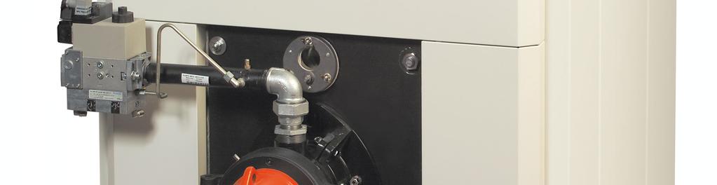
24 SECTION 4 PAGE 22 POTTERTON COMMERCIAL PRODUCTS DIVISION NXR4 Fig. 6 Cable Routing Fig. 7 Fitting Thermometer into Flue CAPILLARIES EARTH WIRE CLAMP NUT A Thermometer Phial Flue Stack Holding Clip Ø7.5 BURNER CABLES Flue Gas Thermometer The housing for the thermometer is positioned on the control panel front and the thermometer in the flue stack. Remove top of control panel and open the front. 2 Remove the factory mounted blanking plate and engage the capillary and the thermometer housing in the front aperture. 3 Guide the capillary through the control panel rear and casing front top parallel to the other installed capillaries. Run the capillary along the insulating blanket towards the back of the boiler to enable the thermometer to be placed in the connection pipe between the flue hood and the stack. 4 Drill, preferably vertically, the flue gas duct to 7.5mm Ø and insert the thermometer holding clip (see Fig. 7). 5 Insert the thermometer into the clip. 6 Close the control panel and refit the top. Burner Cables The NXR4 is supplied as standard fitted with a 7-pin and a 4-pin Weiland plug for connection to the burner. High/Low Burner The 7-pin and 4-pin Weiland plugs should be connected to the respective plugs provided on the burner. Fitting The Burner Check that the burner which has been supplied is the correct burner for the boiler, by checking the specification on the burner card provided. 2 Fit the burner adaptor plates and the boiler gasket to the boiler using the fixing screws provided. 3 Place the burner gasket over the burner fixing studs. 4 Insert the burner draught tube into the firing door aperture with the gasket in position on the mounting flange. Secure in position with the nuts and washers provided.
25 POTTERTON COMMERCIAL PRODUCTS DIVISION SECTION 4 NXR4 PAGE 23 5 Connect the fuel supply to the burner. The fuel supply pipes should be self supporting and not apply undue pressure on the burner. 6 Connect the burner cable and plug to the Weiland plugs from the control panel. 7 Check that the weight of the burner has not affected the sealing of the door to the front section, especially after the door has been opened and closed several times. 8 Larger burners, especially dual fuel types, should be supported independently with a suitable device whilst still allowing the door to be opened. Fig. 8A Boiler & Burner Single Phase Supply Single Phase Supply Common Fused Isolator Single Phase Supply Control M Connections Boiler & Burner Power Supply The NXR4 is supplied with either single phase or three phase burners. The electrical supply to the boiler installation should be connected via a fused isolator. Single Phase Installation Install a 230V 50Hz single-phase electrical supply (min cable rating 6.3A) to the boiler instrument panel. No separate electrical supply for the burner is required. The burner is powered from the instrument panel lead provided (Fig. 8). Fig. 8 Boiler & Burner Power Supply Single Phase Supply Three Phase Installation CAUTION: If the burner motor is supplied with threephase power, control panel single-phase supply must be taken from one of the phases supplying the burner motor. Install a three-phase supply direct to the burner via a fused isolator (sized to fit the burner manufacturer s specification), see Fig. 8. Install a separate V 50 Hz single-phase electrical supply derived from the three-phase supply to the boiler instrument panel. This is fused 6.3A in the instrument panel. Three Phase Supply Common Fused Isolator Single Phase Supply Control Control M Three Phase Supply Isolator Ctrl Panel M Burner Control Box Burner Motor
26 SECTION 4 PAGE 24 POTTERTON COMMERCIAL PRODUCTS DIVISION NXR4 Volt Free Contacts Volt free connection should be taken from the control panel where a 24V signal is provided, see Section 6 for further details. Connecting The Gas Supply The connection should be made to the burner connection (see burner card enclosed with this manual for size required). A union and isolating valve should be fitted close to the burner to allow disconnection of the burner for maintenance and repair. The gas supply should be made through a suitable meter and the local gas undertaking should be consulted to determine the suitability of the meter and gas supply to meet existing and additional demands for gas. The installation should be made in accordance with the requirements of the Gas Safety (Installation & Use) regulations and all other regulations and codes of practice. In particular a manual valve for isolation of the boiler house shall be fitted in an accessible position and readily identifiable. The gas supply should be supported adequately. For large single and multiple installations consideration should be given to the installation of additional gas meters to assist in the monitoring of boiler performance. Attention is drawn to the need for adequately sized pipework according to the maximum gas demand for multiple boiler installations and each boiler shall be provided with an isolating valve so that it is possible to isolate the boiler from a common gas supply for maintenance purposes. Boosters are required if the inlet pressure under full load is less than that recommended by the burner manufacturer (see burner card for details). If a booster is required, the local gas undertaking must be consulted and the booster shall be fitted with a low pressure cut off switch upstream of the booster in the event of reduced pressure and to prevent automatic restart on pressure restoration. The cut off pressure shall be decided by the local gas undertaking. Connecting The Oil Supply FUEL STORAGE AND HANDLING The provisions of BS2869 will normally ensure that the fuel will be of adequate performance. There are winter and summer fuel grades and in order to prevent the fuel waxing under sustained cold and exposed conditions, Class D grade fuel oil should be stored and supplied to the burner at a minimum temperature of 5 C, in line with the fuel supplier s recommendations to suit site conditions. The supply pipe and, where fitted, the return line should consist of copper tube (galvanised steel must not be used), the final connection to the pump inlet port being made with the length of flexible pipe supplied with the burner. Joint should be made with compression fittings, not by soldering. When gravity feed is used (the most common system) the maximum head should not exceed 4m (equivalent to a pressure of 35 kpa). PUMP BLEEDING If the fuel tank is allowed to drain completely it will be necessary to bleed the oil pump free of air by slackening the plug in the pressure gauge port allowing oil to run through until air free. OIL FILTRATION SEDIMENT REMOVAL There is an oil strainer inside the body of the fuel pump and a separate oil filter between the oil pipe from the tank and the oil burner. The oil strainer should be removed and cleaned with paraffin during the pre-season check-up. At the same time the oil filter cartridge should be replaced or cleaned, as appropriate for the type fitted. Bleed fuel pump free of air, as described previous, to remove any trapped air. Draw off any accumulation of water or sediment in the fuel tank by opening the sludge cock in the tank bottom, immediately before any new delivery of fuel. Do not run the burner while the tank is being refilled and, if possible, do not restart for one hour after refilling is concluded. Connecting The Water Supply The flow and return connections should be made to the appropriate manifolds, following the recommendations of CP342 and PM5. It is essential that all pipework connections to the boiler are self-supporting, correctly aligned and allow for free expansion of both boiler and pipework. Care should be taken in the pipework design to prevent strain on the connections. Excessive strain can lead to premature failure of the boiler, which is obviously outside the terms of our warranty. The use of expansion bellows to take up both axial and lateral movement is recommended.
27 POTTERTON COMMERCIAL PRODUCTS DIVISION SECTION 5 NXR4 PAGE 25 Potterton Commercial Customer Commissioning Check List The items listed below have been put together as a guide to what actions should be completed before the commissioning of a boiler takes place. Site access available for persons carrying out the proposed work. 2 Site Managers/Personnel aware that work will be taking place. 3 Boilers correctly erected and cased. 4 Risk assessments carried out on possible risks which may affect the persons carrying out the proposed work. 5 Site wiring complete to boilers. 6 Boilers filled and vented. 7 Controls connected, operable and calling for heat. 8 Sufficient system heating load available to run the boilers in order to complete combustion checks. 9 All system pumps operational and available. 0 Gas supply completed, purged and ready for use (if applicable). Oil supply completed, bled and ready for use (if applicable). 2 Flue system complete, adequate and fully functional. 3 Permanent ventilation complete and adequate. 4 All safety systems fitted and fully operational (e.g. safety valves, fuel shut off devices, flue fans interlocked, etc.) 5 Safe working environment provided. Contravention of Regulations PLEASE NOTE THAT SHOULD ANY ITEMS BE INSTALLED ON A TEMPORARY BASIS, E.G. VENTILATION, FLUES ETC, THEN THE COMMISSIONING ENGINEER WILL NOT BE ABLE TO LEAVE THE BOILERS RUNNING UPON COMPLETION OF COMMISSIONING. THE BOILERS WILL NEED TO BE SHUT DOWN MAKING THEM INOPERABLE AND SHUT DOWN AND WARNING NOTICES WILL BE ISSUED. Boiler Commissioning A lifetime guarantee is available on this boiler when erection and commissioning is carried out by the Potterton service department. Please refer to our standard terms and conditions for further details. IMPORTANT: The boiler must be commissioned following completion of the installation. Operation of an uncommissioned appliance may cause injury to personnel and damage to the boiler/burner unit and could invalidate the manufacturers warranties. Commissioning should only be carried out by personnel approved and competent to do so. This facility is available from Potterton Commercial service offices at the addresses as listed on the back page of this manual. Commissioning of the burner unit should be carried out in accordance with the burner manufacturers handbook provided with combustion adjustments in accordance with the Potterton burner card also provided. Before commencing to commission the burner check the following. Electrical supply is of correct voltage and polarity and earthing is available with certification that all electrical checks have been carried out. 2 Fuel supply is tested for leakage and purged of air. Ensure the burner is suitable for the connected fuel supply and pressure, and purging certificates have been filled in. 3 Boiler and system are filled with water and the operating pressure is within the appliance range. 4 Pumps are operational and any flow proving interlocks are functional. The operation of the pump should be checked, particularly on sealed systems, to ensure that operation does not cause a reduction in pressure within the system below the minimum operating pressure. 5 Ventilation is adequate and, in the case of mechanical ventilation systems, operation of the boiler is inhibited unless the ventilation fan is proved. 6 On mechanically assisted flue systems the operation of the boiler plant should be inhibited unless the mechanical flue system is operational and flow proved.
28 SECTION 5 PAGE 26 POTTERTON COMMERCIAL PRODUCTS DIVISION NXR4 7 The safety valve should be checked to ensure that it is of the correct size and pressure. 8 The cold feed and open vent sizes should be checked. 9 Ensure the burner fitted to the boiler is of the correct specification and size for the boiler and suitable for the fuel supply available (see burner card enclosed with this manual). 0 The burner blast tube has been sealed to the door refractory and the boiler door seal is correct. Following completion of the above checks the burner should be commissioned in accordance with the burner manufacturers handbook provided with the burner. The commissioning form provided at the back of this manual MUST be completed and returned to Potterton Commercial at the address on the back page. Typical combustion figures are: CO 2 - Gas: 9 9.5% Oil: 2 3% CO - Gas: 0 00ppm Oil: 0 Smoke Flue gas temperature (taken at 600mm from the flue outlet on a clean boiler) should be within the range of C. Important Safety It is essential that the following instructions and adjustments are carried out by a qualified engineer who is experienced in blown gas/pressure jet burner commissioning. In the UK it is a legal requirement that when working on blown gas appliances the engineer must be CORGI registered. The manufacturer cannot be held responsible for any consequential damage, loss or personal injury as a result of customers failing to follow these instructions, or as a result of misuse. Emergency Instructions The burners are designed and constructed to meet all of the essential requirements of the GAS APPLIANCE DIRECTIVE 90/396/EEC and under normal circumstances should not give occasion to any hazardous conditions. If such a condition should occur during commissioning or subsequent use of this product, be it a fault of the burner, the boiler or of any instrument, machine or service in the proximity of the burner then the GAS and ELECTRICITY supply to the burner should be IMMEDIATELY ISOLATED until such time that the fault has been investigated and rectified. The commissioning of the appliance can be split into three main categories these being listed below. Pre-Commissioning Dry Run This will enable the checks on the safety controls to be done and should include: Air Control Devices Control Devices Control Box Soundness Testing This is to check the soundness of the gas train and valves and should include: Main Gas Pressure Governor Gas Valve Closure Commissioning Live Run This will enable the burner to be commissioned fully and should include: Checking Inlet Pressures Checking Pipework Checking Pilot Flame Checking Low/High Flame Setting Gas Rates Setting Combustion Figures Checking Flame Signals Pressure Switch Settings IMPORTANT: After each adjustment, gas flow rate and flue gas analysis should be re-checked. ALWAYS use approved test equipment (continually monitoring electronic equipment is recommended). NEVER rely on a visual inspection of the flame as a guide to combustion quality. Following/during commissioning of the burner unit the following additional checks should be carried out. Operation of the control, high/low and high limit thermostats should be checked for correct operation. 2 The flue draught available at the appliance flue outlet should be checked under all operating conditions (hot and cold) and should be within the boiler operating parameters. 3 Checking of lockout of burner on flame failure. OIL Cover the photocell. GAS Disconnect the ionisation probe in the control box (see manufacturer s instructions). 4 Shut down of the boiler plant by external controls does not cause a hazardous condition and pump overrun is provided to remove residual heat from the boiler.
29 POTTERTON COMMERCIAL PRODUCTS DIVISION SECTION 5 NXR4 PAGE 27 5 Following commissioning the boiler overheat and control thermostats should be set to the required operating setting. Additional Checks Where possible the system should be checked to ensure that following purging of air there is no raw water make-up. In particular, when the system is operated in the hot condition, there should be no discharge of water from the safety valve, open vent or cold feed tank overflow that would otherwise lead to unregulated raw water make-up when the system cools down. Fault Finding General fault finding for burner failure should be in accordance with the burner manufacturer s handbook. Set out below are general guidance notes on system fault finding. Overheat Operation The boiler control panel has an inbuilt overheat indicator lamp. Operation of the boiler overheat thermostat is associated with a reduction in boiler water flow. Where overheat operation is reported the following should be checked. The lockout condition can be manually reset by pushing the reset button and the control box should restart its control sequence in an attempt to light the burner. If the control box lockout will not reset or goes to lockout after being reset then the services of a boiler repair/maintenance company should be sought. This service is available form Potterton Commercial Division service offices at the addresses on the back page of this manual. WARNING: The lockout reset button should not be repeatedly operated otherwise a hazardous situation may occur. Should the boiler go to lockout, check the following before attempting to relight the burner. Fuel is available at the burner. 2 The electrical supply to the appliance is of the correct voltage and polarity. The boiler control boxes in some instances have indicator dials as an aid to fault finding on boiler lockout. In these instances refer to the control box manufacturer s data sheet for fault finding details. a) The boiler/system pump is adequate for the duty. b) Operation of flow reducing devices, ie, TRVs, compensated mixing valves, etc., do not reduce the water flow rate through the boiler below the minimum flow rate. c) Pump overrun is incorporated to dissipate residual heat from the boiler on system shut down. d) The operation of boiler back end valves incorporates a time delay to allow for removal of residual heat from the boiler. e) The boiler is operating at the correct rate and is not overfired. The use of a primary loop system is highly recommended to provide a constant boiler flow rate under all operating conditions. For further information please refer to the Potterton Technical Bulletin series. Burner Lockout The package burners supplied with the boiler unit have an integral safety system to allow the safe and reliable operation of the burner. Failure of the burner to operate correctly will cause the burner control box to lockout and the lockout button on the burner will illuminate to indicate this.
30 SECTION 5 PAGE 28 Boiler Maintenance POTTERTON COMMERCIAL PRODUCTS DIVISION Natural Gas & LPG Fired Boilers NXR4 Before starting work a risk assessment should be carried out on the boiler house to determine the safety of the working environment. It is essential for efficient and trouble free operation that the boiler plant is regularly maintained. This must be carried out by qualified and experienced engineers and in the case of gas fired appliances attention is drawn to the mandatory requirement of CORGI registration of personnel undertaking work on these appliances. This facility is available from Potterton Commercial Division service department, details are available on the rear of this manual. Before commencing servicing of a boiler a combustion test must be taken. Boilers should be serviced and re-commissioned as a minimum on an annual basis for gas and twice a year for oil. It is strongly advised that a maintenance contract be entered into with Potterton Commercial Division to ensure that the boiler/burner unit is correctly and properly maintained. WARNING: Isolate the electrical and fuel supplies before attempting any maintenance work. Cleaning of Flue Surfaces The boilers are supplied with a set of cleaning tools comprising of flueway brushes and extension rods for routine cleaning. Boilers may require periodic cleaning with specialist mechanical equipment dependent on boiler conditions, fuel type, etc. Cleaning of the boiler requires opening of the door and removal of the flue covers, front and rear under the flue cover. Frequency of boiler cleaning varies and is dependent on site conditions, fuel type, heat load, design of controls and running conditions. For maximum efficiency and economy in running, it is essential that the combustion chamber and flueway surfaces should be kept clean and free from deposits. Deposits should be disposed of in a manner not to cause inconvenience to any persons. A layer of deposits.5mm thick will reduce the heat transfer through the tube wall by up to 0%. Not only does this waste fuel but the higher flue gas temperatures that result will increase the thermal stress within the boiler and may lead to joint leakage or in extreme cases section failure. We recommend brushing out, twice a year, of the combustion chamber and flueways and the removal of the rear clean out covers to check for deposits in the flue box. Class D Fuel Oil & Class C2 Kerosene The boilers should be brushed out thoroughly at least bi-monthly for Class D (35 second) and Class 2 (28 second) during the heating season but more frequent attention may be necessary dependant on the operating conditions to prevent the formation of hard adherent scale on the tube surfaces. It is essential to ensure that cleaning is carried out throughout the full length of the flue tube passes and that the rear clean out covers are taken off to allow for removal of deposits brushed through into the flue box. Regular cleaning is essential, as a build up of hard deposits can be extremely difficult to remove. Sludge Gas Maintenance of boilers running on these fuels will be required at more frequent intervals, possibly on a weekly basis or even a daily basis dependent on fuel type and quality. Boiler Ancillaries Check the sealing rope on the boiler door is in place and sealing the combustion chamber. Keep a regular check on the condition of the door refractory around the burner draught tube. If there is any deterioration this must be made good immediately to prevent damage to the boiler and burner. Boiler Controls The operation of boiler controls including control thermostat, high/low thermostat and overheat thermostat must be checked every visit. Safety Interlocks The operation of safety interlocks such as flow proving on mechanical flue/ventilation systems must be checked to ensure that operation of the boiler is prevented on a fault. FOLLOWING MAINTENANCE THE BOILERS MUST BE RECOMMISSIONED.
31 POTTERTON COMMERCIAL PRODUCTS DIVISION SECTION 6 NXR4 PAGE 29 Fig. 9 Boiler Wiring Diagram For further Details please refer to the Control Panel Manual
32 SECTION 6 PAGE 30 POTTERTON COMMERCIAL PRODUCTS DIVISION NXR4 Wiring Diagram Legend Legend: STB - Overheat thermostat ZSB - Burner reset ZT - Burner test switch F - Fuse VSC - Overheat indicator light MST - Mains indicator light TR - Safety mode thermostat TR - st stage regulation thermostat TR2-2 nd stage regulation thermostat ZP - Pump switch (not used) L - Live N - Neutral ZG - On/Off switch BRU - Burner connections H - Hours run counters External Interlocks: DG - External interlock UV - Safety interlock XY - Safety interlock Relays - Overheat & Fault Fig. 20 Pump Overrun Using Changeover Pipe Thermostat L L2 L3 Incoming Supply N C NO L Pump Pipe Thermostat Set <55 C NC Auxiliary Contact on Boiler time control, etc
33 POTTERTON COMMERCIAL PRODUCTS DIVISION SECTION 6 NXR4 PAGE 3 NOTES


34 SECTION 7 PAGE 32 POTTERTON COMMERCIAL PRODUCTS DIVISION NXR4 Fig. 2 Boiler Components REAR SECTION SECTION MA REFRACTORY SEALANT 4 SILICONE SEALANT A A A A
35 POTTERTON COMMERCIAL PRODUCTS DIVISION SECTION 7 NXR4 PAGE 33 NXR4 Boiler Parts List (See Fig. 2) ITEM DESCRIPTION PART No QUANTITY Per Boiler Tube of Silicone COM Dependant Refractory Sealant COM Dependant Front Section COM Front Intermediate Section COM Dependant 3 Middle Intermediate Section COM Dependant 4 Rear Intermediate Section COM Dependant 5 Rear Section COM Nipple COM Dependant 9 Tie Rod 409 COM Tie Rod 40 COM Tie Rod 4 COM Tie Rod 42 COM Tie Rod 43 COM Tie Rod 44 COM Tie Rod 45 COM Tie Rod 46 COM Tie Rod 47 COM A Tie Rod Spring Washer COM Combustion Chamber Deflector Plate COM Flange Joint Ring COM Counter Flange Sludge Connection Bottom Front COM A 2 Blanking Plug Not Shown 5 Counter Flange for Thermostat Pockets Top Front COM Thermostat Pockets COM Flue Cover Plate Centre Left COM Flue Cover Plate Centre Right COM Flue Cover Plate Large Left/Right Front & Rear COM Flue Cover Plate Curved Left/Right Rear COM Stud 8mm x 45mm long COM Sealing Tape 5 x 6 for Flue Covers COM Sealing Tape 5 x 6 for Flue Covers (per metre) COM Flue Box COM Flue Box COM Sealing Rope 9mm x 9mm (per metre) COM Flue Adaptor Ø300mm COM7005 Flue Adaptor Ø350mm COM Stud M6 x 55mm COM Flue Clean Out Cover (without stirrup) COM Flow Manifold COM Flow and return Flange PN 6 25mm COM Return Distributor 47 COM Return Distributor 42 to 46 COM Drain Cock Handle COM70004 Drain Cock COM x 20 Bush COM Return Manifold COM Pack of Screws for Boiler Body (Not Shown) COM Sight Glass Cover COM A Sight Glass COM Burner Door Undrilled COM A Burner Door x Ceramic Fibre and x Mineral Wool COM Door Hinge Assembly COM Door Hinge COM Door Closure Plate COM Pack of Screws for Door (Not Shown) COM
36 SECTION 7 PAGE 34 POTTERTON COMMERCIAL PRODUCTS DIVISION NXR4 Fig. 22 Casing Components A NXR4 Casing Parts List (See Fig. 22) ITEM DESCRIPTION RED CASING PART No WHITE CASING PART No 40 Front Support Rail Left & Right Vertical COM COM Rear Support Rail Left & Right Vertical COM COM Longitudinal Support Rail 409 COM COM Longitudinal Support Rail 40 COM COM Longitudinal Support Rail 4 COM COM Longitudinal Support Rail 42 to 47 COM COM A Bracket 42 to 47 Only COM COM Longitudinal Support Rail Rear 42 COM COM Longitudinal Support Rail Rear 43 COM COM Longitudinal Support Rail Rear 44 COM COM Longitudinal Support Rail Rear 45 COM COM Longitudinal Support Rail Rear 46 COM COM Longitudinal Support Rail Rear 47 COM COM Top Panel Front COM S3923EE 46 Top Panel 560mm COM S Top Panel 700mm COM S Top Panel 840mm COM S Top Panel 980mm COM S Front Side Panel Right COM S Front Side Panel Left COM S Angle Fixings COM COM Bottom Brackets COM COM Side Panel 560mm COM S506324
37 POTTERTON COMMERCIAL PRODUCTS DIVISION SECTION 7 PAGE 35 NXR4 ITEM DESCRIPTION Side Panel 700mm Side Panel 840mm Side Panel 980mm Rear Panel Upper Rear Panel Lower Rear Vertical Panel Left & Right Rear Bottom Panel Front Side Panel Right Front Side Panel Left Front Upper Panel Pack of Fixing Screws (Not Shown) RED CASING PART No COM COM COM COM COM COM COM COM COM COM COM WHITE CASING PART No S S S S236EE S50639 S S50635 S50636 S50637 S COM Fig. 23 Control Panel NXR4 Control Panel Parts List (see Fig. 23) ITEM a 2 2a 2b 3 3a a DESCRIPTION Front Panel Front Panel Cover (Not Shown) Hours Run Meter Flue Gas Thermometer Hours Run Caballing (Not Shown) Rear Panel Bolt DZUS Front Panel Support Control Panel Casing Cable Terminal Support Thermostat TXA4C 09 Thermostat Lever Fuse Support Fuse TFS 5 x A Bag of Lights Bag of Switches Thermostat TG400 Cap.2m Thermometer 68.5 x º QTY PART No S37535 S3946 S70023 S S3946 S37874A S50434 S37873H S50433 S36979 S S S S S50970 S50308 S S3442
38 SECTION 7 PAGE 36 POTTERTON COMMERCIAL PRODUCTS DIVISION NXR4 ITEM DESCRIPTION QTY PART No 7 CB20 Module Front Panel S Relay LY2F 220AC S a Alarm Relay S A Basic CB 29 Module Assembly Basic CB 20 Module Wiring S3757 S A CE 00 Module Assembly CE 00 Module Wiring S3760 S Mask G.M.AVA /09 S
 050607 Fax: (08706) 0056 REPORT SENT TO INSTALLER: SITE VISIT (Italics) (Office use Only) DATE: SIGNATURE: INSTALLER NAME & ADDRESS: YES COMMISSIONING NO COMMISSIONING/SITE VISIT DATE:.")
39 COMMISSIONING REPORT ALL BOILER TYPES REPORT No: SITE ADDRESS: Wood Lane, Erdington, Birmingham, B24 9QP. Tel: (08706) Fax: (08706) 0056 REPORT SENT TO INSTALLER: SITE VISIT (Italics) (Office use Only) DATE: SIGNATURE: INSTALLER NAME & ADDRESS: YES COMMISSIONING NO COMMISSIONING/SITE VISIT DATE:.0 BOILER. Type:.2 No. of Sections: Boiler N /Position.3 Serial No..4 Fuel: N/Gas LPG Class C Class D 2.0 BURNER/CONTROLS 2. Type: Atmospheric Pre-Mix Pressure Jet 2.2 Ionisation Probe: UV Cell Thermocouple 2.3 p Make/Model: 2.4 p Serial N : 2.5 p Spec N : 2.6 Control Box Type: 2.7 Electrical Supply: 2.8 Main Gas Valve Type & Size: 2.9 Pilot Gas Valve Type & Size: 2.0 Gas Booster Type & Size: 2. Gas Booster Serial No: 3.0 BURNER SETTINGS 3. Main Burner Injector Size mm 3.2 Pilot Burner Injector Size mm 3.3 Electrode/Ionisation Setting (to manufacturers instructions) 3.4 Are Burners & Injectors Clean 3.5 o Oil Nozzles: High Fire Size: Type: Low Fire Size: Type: 4.0 PRE-COMMISSIONING CHECKS (See Notes) Yes No N/A 4. Is boiler house ventilation as per the relevant B.S. 4.2 Electricity supply fused, isolated & earth wire connected. 4.3 Check external controls allow operation 4.4 Check boiler/system filled and pumps operational & any isolation valves open 4.5 Check gas available at burner 4.6 o Check oil available at burner 4.7 Check gas meter fitted & sized adequately 5.0 FLUE SYSTEM CHECKS Yes No N/A Conventional 5. Flue Type Room Sealed Fan Dilution System Balanced Compartment Plant Room Door Interlocked Fan Assisted 5.2 Draught Stabiliser Fitted 5.3 Is Flue System Clear 5.4 Flue Header Diameter mm 5.5 Stack Diameter mm Flue Type & Diameter Of Connection To Boiler:- 5.6 TYPE../DIAMETER(mm). Where appropriate and for multi boiler installations sketch. details of flue system showing length of runs and diameter Approximate Overall Height m 6.0 COMBUSTION Pilot Low High Unit 6. Inlet Gas Supply Pressure (All Boilers running) mbar 6.2 Burner Pressure mbar 6.3 Gas Rate m 3 /hr 6.4 o Oil Pump Pressure Bar 6.5* Ionisation Probe Current A 6.6 cp Air Shutter Position O 2 % 6.8 CO 2 % 6.9 CO ppm 6.0 o Smoke Number - 6. Nett Flue Gas Temperature o C 6.2 Flue Draught mmwg 6.3 CO 2 At Flue Dilution Outlet % 6.4 Burner Fan Static Pressure mmwg 6.5 Combustion Chamber Resistance mmwg 7.0 OPERATIONAL SAFETY CHECKS 7. Check Control Thermostat Operation 7.2 Check Limit Thermostat Operation 7.3 Check High/Low Thermostat Operation 7.4 Check For Gas Leaks 7.5 Check For Gas Leakage Past Valve Assembly 7.6 o Check For Oil Leaks 7.7* Check Boiler Locks Out On Loss Of Flame Signal 7.8 Check boiler Locks Out On Air Pressure Switch Operation 7.9 Check Boiler Inhibits On Gas Inlet Pressure Switch 7.0 Boiler Locks Out On All Other Safety Functions 7. Check For Flue Spillage 7.2 $ Check Thermocouple Operation 7.3 $ Check Thermocouple Interrupter Operation 7.4 Check Gas Booster Interlock Operational Record Booster INLET and OUTLET Pressure Switch 7.5 Settings:- 7.6 INLET OUTLET. Record Burner/ Boiler INLET and OUTLET Pressure Switch Settings:- INLET OUTLET. 8.0 BOILER/SYSTEM CHECK LIST 8. Control Thermostat Setting 8.2 High/Low Thermostat Setting 8.3 Boiler Water Pressure 8.4 Are Pipework Connections As Per Manual Is Safety Valve Fitted 8.5 If So, SIZE & MAKE:-... O C O C PRESSURE RATING... YES NO 8.6 Are Water Isolating Valves Fitted 8.7 Are Water Flow Switches Fitted 8.8 Are Return Water Shut Off Or Diverter Valves Fitted 8.9 Is Shunt Pump Fitted 8.0 Is Pump Overrun Fitted SYSTEM WATER QUALITY 8. c PH Value ph 8.2 TDS PPM
Derwent Prestige Plus Installation, operation & maintenance manual
 To be kept by the user March 2010 Derwent Prestige Plus Installation, operation & maintenance manual Working towards a cleaner future heating specialists INDEX Section 1 Page Page Fig. 1 - General Data
INDEX. Page SECTION 2. General 5 Standard Supply 5 Controls 5 Optional Extras 5 Shipping Packaging 5 Installation 5 Boiler Siting and Base 6 SECTION 6
 POTTERTON RAPIDO APRIL 2005 INDEX SECTION 1 Page Page Fig. 1 General Data & Dimensions 1 Table 1 Boiler Dimensions 1 Table 2 Combustion Chamber Data 1 Table 3 Technical Data 2 General information 3 Fig.2
DERWENT PRESTIGE MAY 2004
 MAY 2004 INDEX Section 1 Fig 1 - GeneralData & Dimensions 1 Table 1 - BoilerDimensions 1 Table 2 - Connections 1 Table 3 - TechnicalData 5 to 12 Section 2 Table 4 - TechnicalData 13 to 22 Section 3 Fig
GAS FIRED ATMOSPHERIC ELECTRONIC VERSION kw
 GAS FIRED ATMOSPHERIC ELECTRONIC VERSION 51-102 kw GENERAL DESCRIPTION 900 D a3 1000 762 672 E 222 The PEGASUS F2 range of atmospheric natural gas-fired boilers are constructed of cast iron finned sections
ATMOSPHERIC GAS BOILER INSTALLATION, OPERATING AND MAINTENANCE MANUAL
 STREBEL GENEVA CE ATMOSPHERIC GAS BOILER INSTALLATION, OPERATING AND MAINTENANCE MANUAL INDEX TABLE 1 TECHNICAL DATA SECTION 1 SECTION 2 SECTION 3 SECTION 4 SECTION 5 SECTION 6 SECTION 7 SECTION 8 SECTION
Clyde CK40. Cast Iron Boiler. Engineering Data Sheet 663/8 May Natural gas Class D oil Dual Fuel. 350 kw to 500 kw
 atural gas Class D oil Dual Fuel 350 kw to 500 kw Clyde CK40 Cast Iron Boiler Contents Page General information Dimensions 3 Technical data 3 Installation requirements 4 & 5 Boiler control panel 6 Wiring
Cast Iron Boilers. G Series ( kW)
") Cast Iron Boilers G Series (320-1017kW) Mikrotherm G Series Cast Iron Boilers The Mikrotherm G Series of cast iron sectional boilers offer all the advantages of cast iron durability and longevity coupled
Cast Iron Boilers G Series (320-1017kW) Mikrotherm G Series Cast Iron Boilers The Mikrotherm G Series of cast iron sectional boilers offer all the advantages of cast iron durability and longevity coupled
To be kept by the user heating specialists
 To be kept by the user Jan 2010 Arizona 99 930kW Installation, operation & maintenance manual Working towards a cleaner future heating specialists WARNING When the boiler is operated with a pressure jet
Remeha. Fuel oil/gas boilers P 520. Installation and Service Manual A
 Remeha Fuel oil/gas boilers EN Installation and Service Manual 300016859-001-A 63115 Declaration of conformity The appliance complies with the standard model described in declaration of compliance. It
Osprey 2 CFL
 Osprey 2 CFL 125-150 - 180-220 Gas Fired Floor Standing Boiler Installation and Servicing Instructions Please leave these instructions with the user Natural Gas Potterton Osprey 2 CFL 125 G.C.N o 41 590
NXR3. 70 / 290 kw HIGH-EFFICIENCY, PRESSURIZED, CAST IRON, OIL OR GAS BOILERS. 1. Standards - Regulations. 3. Assembly and installation
 I N S T A L L A T I O N M A N U A L NR3 70 / 290 kw HIGH-EFFICIENCY, PRESSURIZED, CAST IRON, OIL OR GAS BOILERS 1. Standards - Regulations 2. General 3. Assembly and installation 4. Installing the options
pressurejetrange Buccaneer GTE, Falcon GTS, Harrier GTS, Viceroy GTS, Viscount GTS, Vanguard L Pressure jet boilers kW
 pressurejetrange Buccaneer GTE, Falcon GTS, Harrier GTS, Viceroy GTS, Viscount GTS, Vanguard L Pressure jet boilers 21-3500kW Commercial & Industrial Boilers the pressure jet range Contents Introduction
INSTALLATION AND OPERATING INSTRUCTIONS GN2. HIGH EFFICIENCY CAST IRON BOILER FOR LIQUID and/or GAS FUELS
 INSTALLATION AND OPERATING INSTRUCTIONS HIGH EFFICIENCY CAST IRON BOILER FOR LIQUID and/or GAS FUELS INDEX 1. Technical information... page 3 2. Dimensional and technical characteristics... page 3 3. Packing
CAST IRON PREMIX HIGH EFFICIENCY GAS FIRED BOILER kw BRILEY DESIGN MANUAL
 BRILEY CAST IRON PREMIX HIGH EFFICIENCY GAS FIRED BOILER 60 140 kw 0604.2 Beeston Briley cast-iron premix gas-fired boiler 60-140kW Contents 1 Boiler specifications Page 3 2 Appliance general dimensions
Synergy Grill User & Engineer Installation & Conversion Guide
 Synergy Grill 1300 User & Engineer Installation & Conversion Guide 1 Index: Description Page Number/Section Important Information 3 Installation 4-6 / Section 1 Commissioning 6 / Section 2 Converting Gas
Pressure Jet Boilers. Pressure Jet Range. Commercial Heating Solutions.
 Boilers Range www.idealcommercialheating.com Introduction - Ideal Commercial & Industrial Contents Pioneering heating solutions since 1905 Here at Ideal, we understand that you want a reliable, long term
SIME FORMAT WALL HUNG BOILERS MODEL 34i AND MODEL 34e. cod A
 cod. 6272262A GENERAL DATA Heating Data Heat Output Input (Adjustable) (Adjustable) Format 34i 11.2 34KW 45 145MJ/hr Format 34e 11.2 34KW 45 145MJ/hr General Specifications FORMAT 34i 34e Main burner injectors
400G/L PX (CF) Servicing Instructions. For use in GB and IE PLEASE READ THESE INSTRUCTIONS BEFORE SERVICING THIS APPLIANCE
 Servicing Instructions. For use in GB and IE PLEASE READ THESE INSTRUCTIONS BEFORE SERVICING THIS APPLIANCE") Servicing Instructions 400G/L PX (CF) For use in GB and IE DESN 511420 C Remember, when replacing a part on this appliance, use only spare parts that you can be assured conform to the safety and performance
Servicing Instructions 400G/L PX (CF) For use in GB and IE DESN 511420 C Remember, when replacing a part on this appliance, use only spare parts that you can be assured conform to the safety and performance
TEMPRA. Wall Mounted Fan Flue System boiler. Wall mounted fanned flue boiler INSTALLATION AND USE INSTRUCTIONS. Appr. nr. B A - CE 0063 AQ 2150
 Wall Mounted Fan Flue System boiler Appr. nr. B 94.04 A - CE 0063 AQ 2150 Phone numbers: Installer Service Engineer Serial N Wall mounted fanned flue boiler INSTALLATION AND USE INSTRUCTIONS Please read
Aluminium range of condensing boilers. Works every time. Designed to meet carbon reduction targets. Lifetime service and support
 Aluminium range of condensing boilers Outputs from 30kW to 600kW Designed to meet carbon reduction targets Lifetime service and support Works every time. www.pottertoncommercial.co.uk Aluminium range of
400GL PX (PF) Servicing Instructions. For use in GB and IE PLEASE READ THESE INSTRUCTIONS BEFORE SERVICING THIS APPLIANCE
 Servicing Instructions. For use in GB and IE PLEASE READ THESE INSTRUCTIONS BEFORE SERVICING THIS APPLIANCE") Servicing Instructions 400GL PX (PF) For use in GB and IE DESN 512548 A Remember, when replacing a part on this appliance, use only spare parts that you can be assured conform to the safety and performance
Servicing Instructions 400GL PX (PF) For use in GB and IE DESN 512548 A Remember, when replacing a part on this appliance, use only spare parts that you can be assured conform to the safety and performance
Ca 6s and BCa 6s kw INSTALLATION AND OPERATING INSTRUCTIONS. Page 1 31/07/00
 Ca 6s and BCa 6s 33-64 kw INSTALLATION AND OPERATING INSTRUCTIONS Page 1 CONTENTS: General specification Dimensions for Ca6s and BCa6s boilers. Boiler room clearance requirements Boiler block assembly
Calder. Steel Hot Water Boiler Suitable for Pressure Jet burners Oil, gas, LPG or dual fuel firing. Outputs kw. Calder Model
 Calder Steel Hot Water Boiler Suitable for Pressure Jet burners Oil, gas, LPG or dual fuel firing Outputs 70-3500 kw Calder Model 70-1300 Calder Model 1400-3500 Calder - Steel Hot Water Boiler The Calder
Mikrofill Ethos Condensing combination boiler
 Mikrofill Ethos Condensing combination boiler User Instructions 24cc CE Mark Mikrofill gas appliances comply with the requirements contained in CE Mark documents contained with European directives applicable
Calder Plus. High Efficiency Steel Hot Water Boiler Suitable for Pressure Jet burners Gas or LPG firing. Outputs kw. Calder Plus Model
 Calder Plus High Efficiency Steel Hot Water Boiler Suitable for Pressure Jet burners Gas or LPG firing Outputs 70-3500 kw Calder Plus Model 70-1300 Calder Plus Model 1400-3500 Calder Plus - High Efficiency
U tube models PTU 09, 12, 15, 25, 30, 35, 40, 45. single linear tube models PTS 09, 12, 15, 25, 30, 35, 40, 45
 U tube models PTU 09, 2, 5, 25, 30, 35, 40, 45 & single linear tube models PTS 09, 2, 5, 25, 30, 35, 40, 45 installation, servicing & operating instructions INSTALLATION, SERVICING AND OPERATING INSTRUCTIONS
Technical information. Remeha P 500. Pressurized boiler. Heat output: kw
 Technical information Remeha P 500 R e m e h a P 5 0 0 Pressurized boiler Heat output: 635-1900 kw Remeha P 500 TABLE OF CONTENT Preface 3 1 Description of the unit 3 1.1 General 3 1.2 Burners 3 2 Construction
BENSON LINEAR RADIANT TUBE
 BENSON LINEAR RADIANT TUBE Natural or Propane (Gas fired) I N S T A L L A T I O N C O M M I S S I O N I N G S E R V I C I N G U S E R I N S T R U C T I O N S September 2001 CONTENTS Page Compliance Notices
TopGas Cascade Condensing Gas Boilers Technical Information and Assembly Manual Output range 60 to 720 kw /17 Subject to modification
 TopGas Cascade Condensing Gas Boilers Technical Information and Assembly Manual Output range 60 to 720 kw Subject to modification Contents 1. Important Information 4 1.1. Documentation 4 1.2. Guarantee
AGA 13 AMP RETRO-FIT WITH AIMS
 AGA 13 AMP RETRO-FIT WITH AIMS (OIL TO ELECTRIC) FITTING INSTRUCTIONS LEAVE WITH CUSTOMER For use in GB and IE 04/14 EINS 515736 OIL TO ELECTRIC CONVERSION INSTRUCTIONS l ISOLATE ELECTRIC SUPPLY, OIL SUPPLY
R e m e h a P Technical Information. Remeha P 300. Pressurized boiler. Heat output: kw
 Technical Information Remeha P 300 R e m e h a P 3 0 0 Pressurized boiler Heat output: 278-709 kw Remeha P 300 CONTENTS Preface 3 1 Description of the unit 3 1.1 General 3 1.2 Burners 3 2 Construction
INSTALLATION AND MANINTENANCE INSTRUCTIONS
 INSTALLATION AND MANINTENANCE INSTRUCTIONS Appr. Nr. A 9503 T - 0085 AQ 0765 PEGASUS F2 T HIGH EFFICIENCY GAS-FIRED CAST-IRON BOILERS Models 51-68 - 85-102 2 Contents 1. General technical data 2. Dimensional
Technical information. Remeha P200. Pressurized boiler. Heat output: kw
 Technical information Remeha P200 R e m e h a P 2 0 0 Pressurized boiler Heat output: 59-256 kw Remeha P 200 CONTENTS Preface 3 1. Description of the unit 4 1.1 General 4 1.2 Burners 4 2. Construction
Superior. A Compact Floor Standing Gas Fired, High Efficiency Condensing Hot Water Boiler. Outputs 120, 160, 200, 240, 280 kw
 Superior A Compact Floor Standing Gas Fired, High Efficiency Condensing Hot Water Boiler Outputs 120, 160, 200, 240, 280 kw 1 The Superior is a, pre-assembled floor standing, gas fired high efficiency
pressurejetrange Buccaneer GTE, Falcon GTE, Harrier GTE, Viceroy GT, Viscount GTE, Vanguard L Pressure jet boilers kW
 pressurejetrange Buccaneer GTE, Falcon GTE, Harrier GTE, Viceroy GT, Viscount GTE, Vanguard L Pressure jet boilers 21-3500kW Commercial & Industrial Boilers the pressure jet range Contents Introduction
TC MODULE (FFD) (with Gas Hob)
 (with Gas Hob)") TC MODULE (FFD) (with Gas Hob) Installation Instructions REMEMBER: when replacing a part on this appliance, use only spare parts that you can be assured conform to the safety and performance specification
TC MODULE (FFD) (with Gas Hob) Installation Instructions REMEMBER: when replacing a part on this appliance, use only spare parts that you can be assured conform to the safety and performance specification
Clyde Alkon 90. Floor standing condensing boilers. Natural Gas. 90 kw. LP Gas. 90 kw
 90 kw Clyde Alkon 90 LP Gas Floor standing condensing boilers Natural Gas 90 kw Contents General information Dimensions and Data Installation requirements Boiler wiring diagram Hydraulic systems Page Fully
INSTALLATION & TECHNICAL MANUAL
 The COMET Range of Boilers the ultimate solution for central heating INSTALLATION & TECHNICAL MANUAL If you require any further assistance: Telephone: 01698 820533 Fax: 01698 825697 E-mail: info@electric-heatingcompany.co.uk
INSTALLATION AND SERVICING
 AND SERVICING HARRIER GTS 5-9 When replacing any part on this appliance, use only spare parts that you can be assured conform to the safety and performance specification that we require. Do not use reconditioned
ProCon Streamline Gas Condensing Boiler. Installation and Operating Manual.
 1 MHG Heating Ltd ProCon Streamline Gas Condensing Boiler. Installation and Operating Manual. Unit 4 Epsom Downs Metro Centre, Waterfield, Tadworth, Surrey, KT20 5LR Telephone 08456 448802 Fax 08456 448803
Stainless steel range of condensing boilers. Designed to meet carbon reduction targets. Lifetime service and support. Outputs from 50kW to 660kW
 Stainless steel range of condensing boilers Outputs from 50kW to 660kW Designed to meet carbon reduction targets Lifetime service and support Totally dependable. page 1 www.pottertoncommercial.co.uk Contents
Assessment Schedule - TS.6
 The Assessor shall determine the business s commitment and support to good and safe working practices; also that it has a positive culture in all aspects of its work. In particular, the assessor shall
AGA TOTAL CONTROL. Model No s: TC3 & TC5 (ROOM VENT OPTION)
") AGA TOTAL CONTROL Model No s: TC3 & TC5 (ROOM VENT OPTION) Installation Guide REMEMBER: when replacing a part on this appliance, use only spare parts that you can be assured conform to the safety and performance
AGA TOTAL CONTROL Model No s: TC3 & TC5 (ROOM VENT OPTION) Installation Guide REMEMBER: when replacing a part on this appliance, use only spare parts that you can be assured conform to the safety and performance
Sirius FS. Working towards a cleaner future
 Sirius FS Floor Standing Stainless Steel Condensing Boilers Single Boiler Applications: 50 to 160kW Modular Boiler Applications: up to 640kW Working towards a cleaner future heating specialists 1. Product
Installation and maintenance instructions
 600 965 0/006 GB For the installer Installation and maintenance instructions Logano GE5 Cast iron sectional boiler for oil or gas pressure jet burners Please read thoroughly prior to installation and maintenance
JOHN DEERE GATOR HPX/XUV 2 PASSENGER HEATER INSTALLATION INSTRUCTIONS (p/n: 9PH20S30)
") P. 1 of 12 JOHN DEERE GATOR HPX/XUV 2 PASSENGER HEATER INSTALLATION INSTRUCTIONS (p/n: 9PH20S30) Item: Qty: Description: 1 2 1 x 1 x 5/8 Tee Fitting 2 2 Plastic Snap-in Hose Grommet 3 4 1-1/2" Hose Clamps
P. 1 of 12 JOHN DEERE GATOR HPX/XUV 2 PASSENGER HEATER INSTALLATION INSTRUCTIONS (p/n: 9PH20S30) Item: Qty: Description: 1 2 1 x 1 x 5/8 Tee Fitting 2 2 Plastic Snap-in Hose Grommet 3 4 1-1/2" Hose Clamps
Savile Plus. Steam Boiler. Suitable for Pressure Jet burners Oil, gas or dual fuel firing. Outputs kg/h
 Savile Plus Steam Boiler Suitable for Pressure Jet burners Oil, gas or dual fuel firing Outputs 380-5425 kg/h 1 Savile Plus - Steam Boiler The Savile Plus is a range of three pass wet back reverse flame
EDENA CLASSIC E. Model : kw INTALLATION AND SERVICING INSTRUCTIONS. Gas Fired Floor Standing Boiler. Réf. : CH I EN 09/05
 INTALLATION AND SERVICING INSTRUCTIONS EDENA CLASSIC E Model : 35-43 - 53-64 kw Gas Fired Floor Standing Boiler N04266.DSF Réf. : CH - 1254 - I - 0 - EN 09/05 1 Réf. : CH - 1254 - I - 0 - EN Contents 1.0
Metropolitan. Steam Boiler. Suitable for Pressure Jet or Rotary Cup burners Oil, gas or dual fuel firing. Outputs kg/h
 Metropolitan Steam Boiler Suitable for Pressure Jet or Rotary Cup burners Oil, gas or dual fuel firing Outputs 1845-21 700 kg/h 1 Metropolitan - Steam Boiler The Metropolitan is a range of high pressure
ferroli Boiler Replacement Maxima 35C- Modena HE
 ferroli Boiler Replacement Maxima 35C- Modena HE Introduction Although the new Ferroli Modena 32C HE high efficiency condensing combination boiler has an output slightly less than that of the Ferroli Maxima
THE SEVERN. Installation Instructions for Freestanding Severn Stove with Boiler PERFORMANCE RATING
 THE SEVERN Installation Instructions for Freestanding Severn Stove with Boiler Consumer Protection Act 1987 As manufacturers and suppliers of cooking and heating products, in compliance with Section 10
TECHNICAL INSTRUCTIONS
 TECHNICAL INSTRUCTIONS 24-Month Maintenance Kit P/N 58015-02 For BMK2.0 (Nozzle Mix) Description of Document: This TID provides the procedures to perform recommended 24-Month maintenance on the following
Technical Data TYPE T14 & T14D TEMPERATURE PILOT SPENCE ENGINEERING COMPANY, INC. 150 COLDENHAM ROAD, WALDEN, NY SD 4511A T14 PILOT
 Technical Data SD 4511A SPENCE ENGINEERING COMPANY, INC. 150 COLDENHAM ROAD, WALDEN, NY 12586-2035 TYPE T14 & T14D TEMPERATURE PILOT PRINTED IN U.S.A. SD 4511A/9811 5 13 /16 D 4 7 /8 1 13 /16 T14 PILOT
JANUS 3 CIRCULATOR WATER HEATER INSTALLATION, COMMISSIONING & SERVICING INSTRUCTIONS G.C. No
 JANUS 3 CIRCULATOR WATER HEATER INSTALLATION, COMMISSIONING & SERVICING INSTRUCTIONS G.C. No 53 416 06 Publication No. ZZ 180/17 May 2000 These appliances are tested and certified by B G Technology for
Bosch Group. 15SBi / 24SBi. WALL MOUNTED BOILERS FOR CENTRAL HEATING and Indirect supply of domestic hot water
 Bosch Group 15SBi / 24SBi WALL MOUNTED BOILERS FOR CENTRAL HEATING and Indirect supply of domestic hot water INSTALLATION AND SERVICING INSTRUCTIONS 24SBi This appliance is for use with Natural Gas or
MULTIPLEX SELF RECUPERATIVE gas burner
 Installation - Maintenance MULTIPLEX SELF RECUPERATIVE gas burner SERIES MPSR The Nu-way Multiplex Recuperative System offers the alternative of a self-recuperative burner or a separate recuperator and
Unvented Calorifier Range. Operating and Maintenance Manual. For Models & 500
 Unvented Calorifier Range. Operating and Maintenance Manual. For Models 125 300 & 500 Telephone 08456 448802 Fax 08456 448803 Emial info@mhgheating.co.uk Web www.mhgheating.co.uk TABLE OF CONTENTS. Section
Installation and maintenance instructions
 6304 4995 0/004 GB For installer Installation and maintenance instructions Flue gas heat exchanger WT50/60 Please read thoroughly prior to installation and maintenance. Summary About this manual This equipment
LP30 High Integrity Low Level Alarm Probe Installation and Maintenance Instructions
 4024750/9 IM-P402-44 AB Issue 9 LP30 High Integrity Low Level Alarm Probe Installation and Maintenance Instructions 1 General safety information 2 General product information 3 Installation 4 Wiring 5
Baxi System 100 HE Plus. User s Operating Instructions. Wall Mounted Powered Flue Condensing Gas Fired Central Heating Boiler
 User s Operating Instructions Baxi System 100 HE Plus Wall Mounted Powered Flue Condensing Gas Fired Central Heating Boiler Please keep these instructions safe. Should you move house, please hand them
INSTALLATION & TECHNICAL MANUAL
 The FUSION Range of Boilers INSTALLATION & TECHNICAL MANUAL If you require any further assistance: Telephone: 01698 820533 Fax: 01698 825697 E-mail: info@electric-heatingcompany.co.uk Or visit our website
USER INSTRUCTIONS & CUSTOMER CARE GUIDE Si II SERIES
 24-28Si II SERIES G.C. NUMBERS APPLIANCE NATURAL GAS L.P.G. 24Si II 47 311 65 47 311 66 28Si II 47 311 67 47 311 68 USER INSTRUCTIONS & CUSTOMER CARE GUIDE EXCELLENCE COMES AS STANDARD CONTENTS Page No.
TECHNICAL INSTRUCTIONS
 TECHNICAL INSTRUCTIONS Benchmark 3.0LN 24-Month Maintenance Kit# 58015-04 This kit applies to units with an Ignitor and a separate gas injector. For units with an Ignitor-Injector (P/N 58023), see Kit
Alpha CD13R,18R and 24R
 Installation and Servicing Instructions Alpha CD3R,8R and 24R Wall Mounted, Fan Assisted, Room Sealed, Gas Fired, High Efficiency Condensing Regular Boiler Range For Technical help or for Service call...
Installation & Service Instructions
 Part No. 966/9350/1 02 Potterton Housewarmer Illusion ASD - G.C. NO. 37 590 16 966 Inset DGF with ILLUSION FACIA Potterton Housewarmer Stratton ASD - G.C. NO. 37 590 17 966 Inset DGF with STRATTON FACIA
Hamworthy. Melbury HE. High Efficiency Steel Shell Power Flame Boilers Gas, Oil, Biofuel or Dual Fuel Burners. Outputs 530kW to 10000kW
 Hamworthy Melbury HE High Efficiency Steel Shell Power Flame Boilers Gas, Oil, Biofuel or Dual Fuel Burners Outputs 530 to 10000 Melbury HE High Efficiency Steel Shell Boilers Gas, Oil, Biofuel or Dual
Description Model Weil-McLain part number. Vent Termination Kit for 3" Stainless Steel All
 Replacement parts Figure 96 Miscellaneous parts Description Model Weil-McLain part number Vent Termination Kit for 3" PVC All 383-500-397 Vent Termination Kit for 3" Stainless Steel All 382-200-430 Vent
MK 8706 / MB 8706 CONCEALED THERMOSTATIC SHOWER VALVE INSTALLATION GUIDE
 MK 8706 / MB 8706 CONCEALED THERMOSTATIC SHOWER VALVE INSTALLATION GUIDE DIMENSIONS 150mm 55mm 200mm 67mm Hot water ¾ BSP Parallel Cold water ¾ BSP Parallel 160mm x 120mm aperture behind face plate for
Vortex 15/21 Utility and Outdoor Module Vortex Combi 21 and Outdoor Vortex Combi 21
 Part No. DOC 38 Rev. 02 January 2007 SUPPLEMENTARY INSTALLATION and SERVICING INSTRUCTIONS Vortex 15/21 Utility and Outdoor Module Vortex Combi 21 and Outdoor Vortex Combi 21 For use with Kerosene only
Installation and Servicing Instructions. Alpha 240/280. Range of Wall Mounted, Fan Assisted, Room Sealed, Gas Fired Combination Boilers
 Installation and Servicing Instructions Alpha 240/280 Range of Wall Mounted, Fan Assisted, Room Sealed, Gas Fired Combination Boilers For Technical help or for Service call... ALPHA HELPLINE Tel: (0322)
Condensing Boilers. Floor Mounted - Evomod, Imax Xtra & Imax Plus III. Commercial Heating Solutions.
 Condensing Boilers Floor Mounted - Evomod, Imax Xtra & Imax Plus III www.idealcommercialheating.com Commercial Heating Solutions Introduction - Ideal Commercial & Industrial Pioneering heating solutions
CP+ Gas & Oil Cabinet Heater Range
 CP+ Gas & Oil Cabinet Heater Range Industrial & Commercial Heating Systems. www.powrmatic.co.uk CP+ CP+EA External Heater HEATING // VENTILATION // AIR CONDITIONING // OEM PRODUCTS CP+ Overview Designed
FITTING, OPERATION, INSTALLATION & SERVICING INSTRUCTIONS
 TRIANCO Electric System Boiler KM 59690 FITTING, OPERATION, INSTALLATION & SERVICING INSTRUCTIONS To be retained by the householder HEALTH AND SAFETY INFORMATION FOR THE INSTALLER AND SERVICE ENGINEERS
DOMINATORPLUS ELECTRIC RANGE APPLIANCES INSTALLATION and SERVICING INSTRUCTIONS
 DOMINATORPLUS ELECTRIC RANGE APPLIANCES INSTALLATION and SERVICING INSTRUCTIONS IMPORTANT The installer must ensure that the installation of the appliance is in conformity with these instructions and National
BAXI BOSTON ALL MODELS FLOOR STANDING OPEN FLUE (OF) CENTRAL HEATING BOILERS INSTALLATION AND SERVICING INSTRUCTIONS. GAS TYPE G20 (Natural Gas)
 CENTRAL HEATING BOILERS INSTALLATION AND SERVICING INSTRUCTIONS. GAS TYPE G20 (Natural Gas)") BAXI BOSTON ALL MODELS FLOOR STANDING OPEN FLUE (OF) CENTRAL HEATING BOILERS INSTALLATION AND SERVICING INSTRUCTIONS GAS TYPE G20 (Natural Gas) BAXI BOSTON 80 OF G.C. No 41 077 65 BAXI BOSTON 70 OF G.C.
BAXI BOSTON ALL MODELS FLOOR STANDING OPEN FLUE (OF) CENTRAL HEATING BOILERS INSTALLATION AND SERVICING INSTRUCTIONS GAS TYPE G20 (Natural Gas) BAXI BOSTON 80 OF G.C. No 41 077 65 BAXI BOSTON 70 OF G.C.
I n s t r u c t i o n m a n u a l f o r b u i l t - i n h o o d. Model code: BORA600
 I n s t r u c t i o n m a n u a l f o r b u i l t - i n h o o d Model code: BORA600 Contact Caple on 0844 8003830 or for spare parts www.4caple.co.uk 1 Y O U R A P P L I A N C E Thank you for buying your
This appliance has been CE-marked on the basis of compliance with the Low Voltage and EMC Directives for the voltages stated on the data plate.
 DOMINATORPLUS ELECTRIC RANGE APPLIANCES INSTALLATION and SERVICING INSTRUCTIONS IMPORTANT The installer must ensure that the installation of the appliance is in conformity with these instructions and National
Male elbow, copper x BSP taper male thread
 Male elbow, copper x BSP taper male thread YP13 Elbow Size Pattern No. Pack 1 Qty Pack 2 Qty Code Barcode Price ( ) ex VAT test 15mm x 1/2" YP13 10 240 08333 5022050083333 16.22 22mm x 3/4" YP13 5 100
2 Super Plus - Installation and Servicing
 CAUTION. To avoid the possibility of injury during the installation, servicing or cleaning of this appliance, care should be taken when handling edges of sheet steel components. 2 Super Plus - Installation
Installation and Operating Manual for the EcoStar 500 Oil Condensing Floor Standing Range Output Range kw
 Installation and Operating Manual for the EcoStar 500 Oil Condensing Floor Standing Range Output Range 15.5 28.4 kw 1 Section 1.0 Appliance Type 1.1 ECOSTAR 500 Standard 1.2 ECOSTAR 500 Enhanced 2.0 Installation
Aluminium range of condensing boilers. Works every time. Designed to meet carbon reduction targets. Lifetime service and support
 Aluminium range of condensing boilers Outputs from 30kW to 600kW Designed to meet carbon reduction targets Lifetime service and support Works every time. www.pottertoncommercial.co.uk Aluminium range of
MULTIPOINT BF Gas Fired Balanced Flue Water Heater
 Please leave these instructions with the user MULTIPOINT BF Gas Fired Balanced Flue Water Heater User Operating, Installation and Servicing Instructions 6 720 607 090 (03.12) JS Natural Gas Main Multipoint
This appliance must be installed and serviced by a competent person as stipulated by the Gas Safety (Installation & Use) Regulations.
 Regulations.") G3512 and G3532 DOMINATORPLUS Grills INSTALLATION and SERVICING INSTRUCTIONS This appliance must be installed and serviced by a competent person as stipulated by the Gas Safety (Installation & Use) Regulations.
G3512 and G3532 DOMINATORPLUS Grills INSTALLATION and SERVICING INSTRUCTIONS This appliance must be installed and serviced by a competent person as stipulated by the Gas Safety (Installation & Use) Regulations.
MULTIPOINT FF Room Sealed Fan-Assisted Water Heater
 Please leave these instructions with the user MULTIPOINT FF Room Sealed Fan-Assisted Water Heater User Operating, Installation and Servicing Instructions 6 720 607 160 (04.02) JS Natural Gas Main Multipoint
Installation guide Sahara & Sahara Plus
 Installation guide Sahara & Sahara Plus Installation requirements. Components for Billi Sahara 310, 320, 360 & 3120 Models Before commencing installation, ensure you have identified the following. 1. Underbench
BWT6.3GL Cooker Hood 60 cm Glass chimney hood
 User Manual for your BWT6.3GL Cooker Hood 60 cm Glass chimney hood NOTE: This User Instruction Manual contains important information, including safety & installation points, which will enable you to get
Installation, operating and servicing instructions
 English 57-115 - 144-1 - 259 Installation, operating and servicing instructions ITALIA EN 1 ITALIA English INDEX WARnINGS 3 Who should read these instructions 3 Symbols 3 Recommendations 3 Importants notes
Performa System 12e, 18e, 24e & 28e
 Performa System 12e, 18e, 24e & 28e Gas Fired Wall Mounted System Boilers Installation and Servicing Instructions Please leave these instructions with the user Natural Gas Potterton Performa System 12e
Imperial Electric Fires
 Imperial Electric Fires GB IE MODELS: Flamescape II Curvascape II manual & remote. Installation and User Instructions PLEASE READ THESE INSTRUCTIONS CAREFULLY AND RETAIN FOR FUTURE REFERENCE This electric
Installation & Servicing Instructions
 Installation & Servicing Instructions Baxi System 35/80 IE & 60/100 IE Gas Fired Wall Mounted System Boiler Please keep these instructions safe. Should you move house, please hand them over to the next
Servicing manual. Wall-mounted condensing gas boiler 600 Series - 11S / 19S / 24S / 24C /2002 GB(EN) For trade use
 For trade use") GB122 7210 1300-12/2002 GB(EN) For trade use Servicing manual Wall-mounted condensing gas boiler 600 Series - 11S / 19S / 24S / 24C Please read thoroughly before attempting to diagnose fault List of contents
GB122 7210 1300-12/2002 GB(EN) For trade use Servicing manual Wall-mounted condensing gas boiler 600 Series - 11S / 19S / 24S / 24C Please read thoroughly before attempting to diagnose fault List of contents
OPTIMA RADIANT TUBE HEATING SYSTEMS. Operation, maintenance and servicing manual
 OPTIM RDINT TUBE HETING SYSTEMS Operation, maintenance and servicing manual CONTENTS GENERL INSTRUCTIONS Section Title Page 1. Preparing the Installation 4 2. Checking the Installation rea 5 3. Flue Connection
BWTC6510GL Cooker Hood 60 cm Glass cooker hood in stainless steel. BWTC9510GL Cooker Hood 90 cm Glass cooker hood in stainless steel
 User Manual for your BWTC6510GL Cooker Hood 60 cm Glass cooker hood in stainless steel BWTC9510GL Cooker Hood 90 cm Glass cooker hood in stainless steel NOTE: This User Instruction Manual contains important
HW3 Handwash Installation and Operating Instructions
 HW3[16]instructions 10/12/15 14:05 Page 1 HW3 Handwash Installation and Operating Instructions IMPORTANT SAFEGUARDS SPECIFICATION: HW3 RATING: 230-240V, 3000W, ~50Hz; DIMENSIONS: 170w x 190h x 80d mm;
Union coupling. copper x copper. Cone joint to BS 1010.
 Union coupling. copper x copper. Cone joint to BS 00. YP Size Pattern No. Pack Qty Pack 2 Qty Code Barcode Price ( ) ex VAT 8mm YP 5 00 08250 502205008250 2.78 5mm YP 0 00 0825 502205008250 8.4 22mm YP
ESS. Installation & Servicing Instructions THESE INSTRUCTIONS TO BE RETAINED BY USER
 ESS Installation & Servicing Instructions THESE INSTRUCTIONS TO BE RETAINED BY USER Contents Design principles & operating sequence Page 1.1 Principle components 2 1.2 Mode of operation (at rest) 2 1.3
Buccaneer G.T. Installation, Assembly and Servicing. Oil or Dual Gas Fired Boilers
 Buccaneer G.T. Installation, Assembly and Servicing Oil or Dual Gas Fired Boilers Assembly and Installation Instructions for Ideal Buccaneer GT Oil, Gas or Dual Fired heating boilers should be read in
Mynute. Installation & Servicing Instructions. 28e THESE INSTRUCTIONS TO BE RETAINED BY USER
 28e Installation & Servicing Instructions THESE INSTRUCTIONS TO BE RETAINED BY USER Contents Design principles & operating sequence Page 1.1 Principle components 2 1.2 Mode of operation 2 1.3 Safety devices
Mini Tender Section 1.1 External Wall Insulation, Mechanical and Electrical Installation
 Mini Tender Section 1.1 External Wall Insulation, Mechanical and Electrical Installation BOILER ONLY INSTALLATION ALL ITEMS BLEOW SHOULD BE INCLUDED WITHIN TENDER COST OR CONSIDER WITHIN BIDDERS SUBMISSION
CARVER CASCADE 2 & CASCADE 2 GE CARAVAN WATER HEATER INSTALLATION INSTRUCTIONS LEAVE THESE INSTRUCTIONS WITH THE USER
 CARVER - CASCADE 2 & CASCADE 2 GE CARAVAN WATER HEATER INSTALLATION INSTRUCTIONS LEAVE THESE INSTRUCTIONS WITH THE USER 1:0 SPECIFICATIONS Water capacity Water connections Water supply 9 litres (2 gallons)