Installation, Start Up and Service Instructions
|
|
|
- Lynn Patrick
- 5 years ago
- Views:
Transcription
1 Installation, Start Up and Service Instructions BHC & HBC Series Heat Pump BAC & ABC Series Air Conditioner IMPORTANT READ BEFORE INSTALLING 1. Read and become familiar with these installation instructions before installing this unit. 2. Be sure the installation conforms to all applicable local and national codes. 3. These instructions contain important information for the proper maintenance and repair of this equipment. Retain these instructions for future use. CONTENTS Page SAFETY CONSIDERATIONS 1,2 PRE INSTALLATION Rigging Installation General Uncrating Accessories Model Nomenclature Unit Positioning Unit Isolation Refrigerant Piping Condensate Drain Fan Motors and Drives Power Supply and Wiring Connecting Ductwork Return Air Filters Start Up Service Panels Fan Motor Lubrication Fan Shaft Bearings Centering Fan Wheel Fan Shaft Position Adjustment Individual Fan Wheel Adjustment Fan Belts Fan Rotation Fan Pulley Alignment Pulley and Drive Adjustment Condensate Drains Coil Removal Cleaning Cooling Coil Replacing Filters Cleaning Insulation Start Up Checklist Parts Warranty to 20 Ton SAFETY CONSIDERATIONS WARNING Improper installation, adjustment, alteration, service, maintenance, or use can cause explosion, fire, electric shock, or other occurrences which may injure you or damage your property. Consult qualified installer or service agency for information or assistance. The qualified installer or agency must use only factory-authorized kits or accessories when modifying this product. Understand the signal words DANGER, WARNING, and CAUTION. These words are used with the safety-alert symbol. Danger identifies the most serious hazards which will result in severe personal injury or death. Warning indicates a condition that could result in personal injury. Caution is used to identify unsafe practices which would result in minor personal injury or product and property damage. Installing, starting up, and servicing this equipment can be hazardous due to system pressures, electrical components and equipment location (elevated structures, etc.). Only trained, qualified installers and service mechanics should install, start up, and service this equipment. Untrained personnel can perform basic maintenance functions such as cleaning coils, and cleaning and replacing filters. All other operations should be performed by trained service personnel. When working on the equipment, observe precautions in the literature and on tags, stickers, and labels attached to the equipment. 1. Follow all safety codes. 2. Wear safety glasses and work gloves. 3. Use care in handling, rigging, and setting bulky equipment. WARNING Be sure all power to equipment is shut off before performing maintenance or service. More than one disconnect may be present. 1. The power supply (v, ph, and Hz) must correspond to that specified on unit rating plate. 2. The electrical supply provided by the utility must be sufficient to handle load imposed by this unit. 3. This installation must conform with local building codes and with the NEC (National Electrical Code) or ANSI (American National Standards Institute)/NFPA (National Fire Protection Association) latest revision. Refer to provincial and local plumbing or wastewater codes and other applicable local codes. Printed in Mexico /28/10
2 MODEL NUMBER IDENTIFICATION GUIDE FOR MODEL NUMBERS THAT BEGIN WITH B MODEL NUMBER B H C 090 M 1 A PRODUCT FAMILY Engineering Digit Air Handler Units BLOWER DRIVE OPTIONS TYPE 1 = Medium Static Drive H= Heat Pump 2 = High Static Drive A = Air Conditioner VOLTAGE H = 208/ M = 208/230/ DESIGN SERIES L = S = COOLING CAPACITY (NOMINAL BTUH) = 6 Ton = 7 1/ = 10 Ton = 12 1/2 Ton = 15 Ton MODEL NUMBER IDENTIFICATION GUIDE FOR MODEL NUMBERS THAT BEGIN WITH A or H MODEL NUMBER H B C 090 M 1 A TYPE H= Heat Pump A = Air ConditionerPackaged PRODUCT FAMILY Air Handler Units Engineering Digit BLOWER DRIVE OPTIONS 1 = Medium Static Drive 2 = High Static Drive VOLTAGE H = 208/ L = DESIGN SERIES S = M = 208/230/ COOLING CAPACITY (NOMINAL BTUH) = 6 Ton = 7 1/ = 10 Ton = 12 1/2 Ton = 15 Ton = 20 Ton PRE-INSTALLATION Rigging All units can be rigged by using the shipping skid. Units are shipped fully assembled. Do not remove shipping skids or protective covering until unit is ready for final placement; damage to bottom panels can result. Use slings and spreader bars as applicable to lift unit. INSTALLATION General Allow 2 1 / 2 ft at front and side of unit for service clearance and airflow. For units equipped with an economizer, refer to the accessory installation instructions for additional clearance requirements. Be sure floor, wall, or ceiling can support unit weight. Figure 1 Styrofoam Shipping Pad Removal Uncrating Move unit as near as possible to final location before removing shipping skid. Remove metal banding, top skid, and plastic wrap. Examine unit for shipping damage. If shipping damage is evident, file claim with transportation agency. Remove base skid just prior to actual installation. NOTE: Be sure to remove the styrofoam shipping pad from the thermostatic expansion valve (TXV). Verify that it has been removed. See Fig. 1. Accessories Refer to instructions shipped with each accessory for specific information. Unit Positioning The unit can be mounted on the floor for vertical application with return air entering the face of the unit and supply air discharging vertically through the top of the unit. The unit can also be applied in a horizontal arrangement with return air entering horizontally and the supply air discharging horizontally. When applying the unit in a horizontal arrangement, ensure the condensate drain pan is located at the bottom center of the unit for adequate condensate disposal. See Fig. 2 for condensate connections for each unit position. Typical positioning and alternate return air locations are shown in Fig. 2. Alternate return air locations can be used by moving the unit panel from the alternate return air location to the standard return air location. Refer to overhead suspension accessory drawing (Fig. 3) for preferred suspension technique. The unit needs support underneath to prevent sagging. 2
3 IMPORTANT: Do NOT attempt to install unit with return air entering top panel of unit. Condensate will not drain from unit. Figure 2 Typical Unit Positioning system, however, some field supplied components may be required. See the following two sections. CHC/HCC090 with 090 HEAT PUMP SYSTEM PIPING Addition of a liquid solenoid valve (LLSV) is recommended when the piping system length exceeds 75 feet. The LLSV must be a bi-flow type suited for use in heat pump systems. The recommended valve is Sporlan model CB14S2 ( 5 / 8 -in. ODF, 7 / 8 -in. ODM). This solenoid valve requires Sporlan part no. MKC-2 coils that must be purchased locally. Wire the solenoid valve in parallel with the compressor contactor coil. The LLSV must be installed at the outdoor unit with the flow arrow pointed toward the outdoor unit (in-flow direction for the heating mode.) Accessory Line Alternate Air Intake and Discharge Air Intake and Discharge Unit Isolation Where extremely quiet operation is essential, install isolators between floor and base of unit, or between ceiling and top section of unit. Be sure that unit is level and adequately supported. Use channels at front and sides of unit for reference points when leveling. Refrigerant Piping For ease in brazing, it is recommended that all internal solder joints be made before unit is placed in final position. The direct-expansion units have internal factory-installed thermostatic expansion valves (TXVs), distributors, and nozzles for use with R-22. Knockouts are provided in the unit corner posts for and 090 and refrigerant piping. The 0 unit requires additional field-fabricated piping access holes. See Fig. 4, which also lists recommended knockouts and access holes to use for each and unit size. Recommended fittings are listed in Table 1. The sensor bulb capillary tubes must be routed from the TXVs inside the unit through one of the piping access holes. Clamp the TXV sensor bulb on a vertical portion of the suction line, outside the unit. See Fig. 5. NOTE: Be sure to remove the styrofoam shipping pad from the TXV. Verify that it has been removed. See Fig. 1. IMPORTANT: Never attach the sensor to the suction manifold. Do NOT mount the sensor on a trapped portion of the suction line. The Series evaporator coils have a face-split design. Ensure that lower circuit of coil is first on/last off when connected to the condensing unit and/or system controls. See Fig. 6. External TXV equalizer connections are provided and factory-brazed into the coil suction manifolds. If suction line must be horizontal, clamp bulb to suction line at least 45 degrees above bottom, at approximately the 4 o clock or 8 o clock position. See Fig. 7. NOTE: The units are supplied with factory-installed thermostatic expansion valves and check valve bypasses. No extra piping connections or kits are required to install the BHC/ HBC with a CHC/HCC condensing unit in a heat pump 3
4 Fig. 3 Preferred Suspension Technique SIZES 6 to 10 Ton SIZES 12 1/2 to 20 OVERHEAD SUSPENSION ACCESSORY NOTE: Dimensions in [ ] are millimeters. SIZES 028,034 4
5 Table 1: Fitting Requirements ACCESS HOLE NO.* CONNECTION TYPE CIRCUIT 1 Suction 3 Liquid 1 Suction 3 Liquid FITTINGS REQUIRED (in.) 1 1 / 8 Street Elbow 1 1 / 8 Nipple, 10 5 / 8 L 5 / 8 Street Elbow 5 / 8 Nipple, 8 5 / 8 L 5 / 8 Long Radius Elbow 1 1 / 8 Street Elbow 1 1 / 8 Nipple, 8 5 / 8 L 5 / 8 Street Elbow 5 / 8 Nipple, 8 5 / 8 L 5 / 8 Long Radius Elbow 1 Suction Lower (2) 1 1 / 8 Street Elbow 5 / 8 Street Elbow 2 Liquid Lower 5 / 8 Nipple, 8 1 / 2 L 5 / 8 Long Radius Elbow 3 Liquid Upper 5 / 8 Street Elbow 5 / 8 Nipple, 13 1 / 2 L 5 / 8 Long Radius Elbow 4 Suction Upper 1 1 / 8 Nipple, 5 3 / 4 L 1 1 / 8 Nipple, 12 L 1 Suction Lower (2) 1 1 / 8 Street Elbow 5 / 8 Street Elbow 2 Liquid Lower 5 / 8 Nipple, 5 1 / 2 L 5 / 8 Long Radius Elbow Liquid Upper 4 Suction Upper 1 Suction Lower 2 Liquid Lower 3 Liquid Upper 5 / 8 Street Elbow 5 / 8 Nipple, 10 1 / 2 L 5 / 8 Long Radius Elbow 1 1 / 8 Nipple, 5 5 / 8 L 1 1 / 8 Nipple, 12 L 1 1 / 8 Street Elbow 1 1 / 8 Nipple, 7 5 / 8 L 5 / 8 Street Elbow 5 / 8 Nipple, 1 7 / 16 L 5 / 8 Long Radius Elbow 5 / 8 Street Elbow 5 / 8 Nipple, 11 1 / 2 L 5 / 8 Long Radius Elbow 4 Suction Upper Table 1 Fitting Requirements *See Fig. 4 for access hole location by number. Fittings are listed in order from header or tee stub connection out to access hole in corner support post. 1 1 / 8 Nipple, 5 5 / 8 L 1 1 / 8 Nipple, 13 L 5
6 Table 1 Fitting Requirements (cont) ACCESS HOLE NO.* CONNECTION TYPE CIRCUIT 1 Suction Lower 2 Liquid Lower 3 Liquid Upper 4 Suction Upper 3 Suction Lower 5 Liquid Lower 6 Liquid Upper 7 Suction Upper 1 Suction Lower 2 Liquid Lower 3 Liquid Upper 4 Suction Upper FITTINGS REQUIRED (in.) 1 1 / 8 Street Elbow 1 1 / 8 Nipple, 2 3 / 4 L 5 / 8 Street Elbow 5 / 8 Nipple, 1 3 / 8 L 5 / 8 Long Radius Elbow 5 / 8 Street Elbow 5 / 8 Nipple, 11 1 / 2 L 5 / 8 Long Radius Elbow 1 1 / 8 Nipple, 5 5 / 8 L 1 1 / 8 Nipple, 13 L 1 1 / 8 Nipple, 3 L 5 / 8 Nipple, 2 7 / 8 L 5 / 8 45 Elbow 5 / 8 Nipple, 1 5 / 8 L 5 / 8 Long Radius Elbow 5 / 8 Nipple, 2 7 / 8 L 5 / 8 45 Elbow 5 / 8 Nipple, 4 1 / 4 L 5 / 8 Long Radius Elbow 1 1 / 8 Nipple, 5 L 1 1 / 8 45 Elbow 1 1 / 8 Nipple, 8 3 / 4 L 1 1 / 8 Street Elbow 1 1 / 8 Nipple, 7 5 / 8 L 5 / 8 Street Elbow 5 / 8 Nipple, 6 1 / 2 L 5 / 8 Long Radius Elbow 5 / 8 Street Elbow 5 / 8 Nipple, 9 1 / 2 L 5 / 8 Long Radius Elbow 1 1 / 8 Nipple, 5 5 / 8 L 1 1 / 8 Nipple, 11 L Table 1 Fitting Requirements *See Fig. 4 for access hole location by number. Fittings are listed in order from header or tee stub connection out to access hole in corner support post. 6
7 Use Hole Field Fabricated Hole Diameters in. (mm) Field Fabricated Hole Position Dimensions, In.(mm) Numbers No. 5 No. 6 No. 7 No. 8 A B C D , , 2, 3, 4 3*, 5, 6, 7 1 1/8 (28.6 ) 1 1/8 (28.6) 1 3/4 (44.5) 3.25 (82.6) (155.6) (263.7) *Must be enlarged from 1 1 / 8 in. to 1 3 / 4 inches. NOTE: Access hole knockouts 1-4 are factory-supplied. Fig. 4 Refrigerant Piping Access Holes LEGEND TXV Thermostatic Expansion Valve NOTE: Component location arrangement shown for field installation of sight glasses, solenoid valves, filter driers, and TXV sensing bulbs. The TXVs and equalizer lines are factory installed. Fig. 5 Face-Split Coil Suction and Liquid Line Piping (Typical) 7
8 FIRST ON/LAST OFF = B VERTICAL INSTALLATION FIRST ON/LAST OFF = A HORIZONTAL INSTALLATION Fig. 6 Typical Evaporator Coil Connections (, ) LEGEND TXV Thermostatic Expansion Valve NOTE: The 8 o clock position is shown above. Fig. 7 TXV Sensing Bulb Location 8
9 Condensate Drain Install a trapped condensate drain line to unit connection as shown in Fig. 9. The unit drain connection is a PVC stub. See Fig. 10. Some areas may require an adapter to connect to either galvanized steel or copper pipe. For these applications, install a field-supplied threaded PVC adapter. NOTE: A trap must be installed in the condensate drain line to ensure that the static pressure of fans is balanced with the water column in the drain line and that condensate can drain completely from pan. Without a trap, air can be drawn up drain line until water level in condensate pan becomes equal to static pressure created by fans, preventing complete drainage. Conditions will worsen as filters become dirty. Install clean-out plugs in trap. Pitch drain line downward to an open floor drain or sump. Provide service clearance around drain line to permit removal of unit panels. Observe all local sanitary codes. NOTE: As shipped, the unit s condensate drain pan is NOT sloped towards the drain connection. The pan slope must be changed to pitch towards the side of the unit with the drain connection. See Fig. 10. Loosen the 2 screws next to the drain outlet at both ends of the unit, push drain pan down in the slots near the drain connection, and up in the slots on the opposite end. Retighten screws. The pan should have a pitch of at least 1 / 4 -in. over its length toward the drain connection. Fan Motors and Drives Motor and drive packages are factory installed in all units. The standard motor and drive packages consist of the following items: 1 fan motor 1 adjustable motor pulley 1 fan pulley 1 fan belt (075, 090 units) 2 matched fan belts (240 units) For instructions on changing fan rotation, changing drive speeds and adjusting drives, see Pulley and Drive Adjustment in the Service section. Fig. 10 Condensate Drains NOTE: Dimensions in [ ] are in millimeters. Fig. 9 Drain Pan Slope Adjustment 9
10 W Power Supply and Wiring Check the unit data plate to ensure that available power supply matches electrical characteristics of the unit. Provide a disconnect switch of size required to provide adequate fan motor starting current. Install disconnect switch and power wiring in accordance with all applicable local codes. See Fig and the unit label diagram. For units with motor sizes less than 5 Hp (3.7 kw), connect power wiring to unit with no. 10 ring terminal. For units with motor sizes of 5 Hp (3.7 kw) or more, connect power wiring with 1 / 4 -in. ring terminal. 105 C 600V RJ A FAN SCROLL MOTOR AND DRIVE CONDENSATE DRAIN CONNECTION (HORIZONTAL) FILTER ELEMENTS FILTER RETAINER CLIP FAN CONTACTOR BOX WIRE ACCESS FAN DRIVE PULLEY COIL TXV BULB ACCESS REFRIGERANT/ Refrigerant CHILLED Piping Access WATER PIPING ACCESS CONDENSATE DRAIN CONNNECTION (VERTICAL) FAN CONTACTOR 24V TERMINAL BLOCK POWER WIRING KNOCKOUT Fig. 12 Fan Contactor Box and Terminal Block Cover Removed (Typical) Table 2 Fan Contactor Coil Data, VOLTAGE (vac) 11 MAXIMUM HOLDING VA 6 to 20 Ton LEGEND TXV Thermostatic Expansion Valve Fig. 11 Wiring and Service Access (Side Panel Removed) The and size 6 to 15 ton units (except with high static drive option) that have motors wired for 460-v, 3-ph, 60 Hz operation can be field-converted to 208/230-v, 3-ph, 60 Hz operation. Rewire the motor according to the diagram plate on the motor. After reconfiguring the motor, mark the motor specifying 208-v or 230-v operation replacing the 460-v sticker information on the units corner post. Fan motors are factory installed on all units. Indoor-fan contactors are located in the fan contactor box behind the side access panel (see Fig. 11 and 12). Wire the thermostat to the 24-v control circuit terminal block located in the side of the fan contactor control box, according to Fig. 13 or the unit label diagram. If the air handler is part of a split system, complete the wiring from the condensing unit to the thermostat shown in Fig. 14. Connecting Ductwork DISCHARGE CONNECTIONS Duct flanges are factory supplied; they are shipped inside the unit attached to the hairpin end of the coil tube sheet for field installation. Using the existing screws, install the duct flanges on the unit s fan deck. Each fan discharge requires 2 flanges; each flange must be bent in the middle to conform to the discharge opening. See Fig. 14. After flanges are installed, connect them to the supply duct using a canvas connection to prevent vibration. It is important that this connection be properly fabricated to prevent high air friction losses and air noise. RETURN CONNECTION When using return-air ductwork, route return-air duct to the unit s return air inlet near the filter rack, using a canvas connection to prevent transmission of unit vibration. If the duct blocks off the unit s access panel, provide a slip joint in the ductwork to permit removal for servicing. OUTDOOR-AIR INLET CONNECTION Connect outdoor-air inlet to field-installed accessory economizer. Refer to economizer. Return-Air Filters Air filters are factory-supplied and installed. In all units with 2 fans, a filter replacement tool (hook) is shipped inside the unit for field use when replacing filters. See the Service section for instructions on filter element replacement. 10
11 Terminal Block TB1 Only LEGEND EQUIP... Equipment GND..... Ground HC Heating Contactor HTR..... Electric Heater IFC Indoor Fan Contactor IFM Indoor Fan Motor TB Terminal Block T STAT... Thermostat Factory Wiring Field Control Wiring NOTE: Use copper conductors only. Fig. 13 Unit Wiring Fig. 14 Duct Flange Connection 11
12 START-UP Before starting unit, check the following and correct as necessary: Is unit solidly supported? Is fan adjusted for speed and pulley alignment? Are pulleys, motor, and bearings securely mounted? Are there any loose parts that will rattle or vibrate? Is condensate drain pan pitched for correct drainage? Are coil baffle plates tight against coil to prevent air bypass? Are all panels securely fastened? Are all electrical connections correct and tight? Also refer to condensing unit instructions before starting a split system. A split system start-up checklist is provided in the back of these instructions. SERVICE Inspection and maintenance should be performed at regular intervals and should include the following: Complete cleaning of cabinet, fan wheel, cooling coil, condensate pan and drain, heating coils, and return-air grille (if present). Inspection of panels and sealing of unit against air leakage. Adjustment of fan motor, belt, bearings, and wheels. Cleaning or replacement of filters. Testing for cooling/heating system leaks. Checking of all electrical connections. Most unit service can be performed by removing one or both of the unit s side panels. Coil cleaning or removal or insulation cleaning may require removal of a rear, top, or bottom panel, depending on the unit s orientation. When service is completed, replace unit panels. Panels Panels are fastened to unit frame with sheet metal screws. Fan and coil compartment must be sealed tightly after service to prevent air from bypassing the cooling coil. Fan Motor Lubrication Fan motor supplied with unit is permanently lubricated and requires no further lubrication. Fan Shaft Bearings Bearings on 6 to 10 ton units are sealed, permanently lubricated bearings that require no further lubrication. 12 to 20 ton units have pillow-block bearings (Fig. 15) that must be lubricated with suitable bearing grease approximately every 3 months. See Table 3 for suitable lubricants. Table 3 Lubricant Data MANUFACTURER LUBRICANT Mobil Mobilplex EP No. 2 Sunoco Prestige 42 Texaco Multifak 2 Texaco Regal AFB-2* *Preferred lubricant because it contains rust and oxidation inhibitors. Fig. 15 Fan Shaft, Bearings, and Fan Wheel (Typical) Fig. 16 Fan Shaft Bearing Centering Fan Wheel If fan and fan shaft assembly are not properly centered, blades may scrape against scroll or may create an objectionable whistling noise. It may be necessary to adjust individual fan wheels or move entire fan shaft. See the following two sections. Fan Shaft Position Adjustment Loosen setscrew or locking collar of each fan shaft bearing. Slide shaft into correct position and replace locking collar (Fig. 16). To replace locking collar, push collar up against inner face of bearing. Turn collar in direction of fan rotation until tight, and tighten setscrew. Tightening locking collar in direction of fan rotation results in further tightening of collar should setscrew work itself loose. 12
13 Individual Fan Wheel Adjustment Loosen the 2 locking bolts holding fan wheel hub to shaft. See Fig. 15. Position fan wheel in center of the fan housing and tighten locking bolts. Clearance between wheel and housing should be the same on both sides. Fan Belts Motor mounting plate and motor support angles are slotted to permit both vertical and horizontal adjustment. Adjust belt(s) for correct deflection by loosening motor plate mounting bolts, moving motor/plate assembly forward or back, and retightening bolts. Press down on belt with one finger midway between fan and motor pulleys to check deflection. For units with motor sizes up to and including 3.7 Hp (2.76 kw), correct deflection is 3 / 16 -in. (4.8 mm) For larger motor sizes, correct deflection is 1 / 8 -in. (3.2 mm). See Fig. 17. If complete belt replacement is required during servicing, loosen the motor plate mounting bolts (Fig. 18), move motor/ plate assembly towards fan pulley, and pull belt(s) off pulleys. Reverse the procedure with new bolts and readjust deflection. Fan Rotation Correct fan rotation with respect to fan outlet is shown in Fig. 18. To reverse the direction of rotation of a 3-phase fan motor, reverse any 2 of the power leads. Refer to the connection diagram on the inside of motor terminal box cover for proper reversing procedure of single-phase motor. Fig. 17 Fan Motor Mounting 13
14 speed and away from fixed flange to reduce speed. Before tightening setscrew, make certain that setscrew is over nearest flat surface of pulley hub (Fig. 19). Increasing fan speed produces a greater load on motor. Do not exceed rated capacity of motor. Condensate Drains Keep condensate drains free of dirt and foreign matter. Return-Air Filters Refer to Replacing Filters section for filter accessibility and removal. Replace with clean filters. Coil Removal Remove unit panels and corner posts as required. Disconnect coil connections and remove fastening screws. Remove coil through end or side sections of unit. Fig. 18 Fan Rotation Cleaning Cooling Coil Remove return-air filters. Remove any heavy dirt that may have accumulated on underside of coil. Coil can be cleaned more easily with a stiff brush, vacuum cleaner, or compressed air when coil is dry. If coil is wet or if water is to be used for cleaning, guard against splashing water on electrical components or damaging surrounding area. Clean coil baffles as applicable and check for tight fit to be sure air does not bypass coil. Cleaning Insulation The insulation contains an immobilized antimicrobial agent that helps prevent the growth of bacteria and fungi. Clean the inner surface of the insulation according to the maintenance instructions in this manual. Fig. 19 Fan Pulley Adjustments Fan Pulley Alignment Align as follows: 1. Loosen setscrews on pulleys. 2. Align pulleys visually and tighten setscrews on fan pulley to lock it in place. 3. Use the methods shown in Fig. 19 to check proper pulley alignment. 4. If pulleys are not in correct alignment, loosen the motor holddown bolts and slide the motor axially until the pulleys are aligned. 5. Tighten motor holddown bolts. Pulley and Drive Adjustment To obtain desired fan speed, refer to the fan motor and drive data in Tables 8A-10D and adjust fan motor pulley as follows: 1. Remove belt from fan motor pulley after loosening motor from motor base. 2. Loosen setscrew in moveable flange of pulley. Screw moveable flange toward fixed flange to increase the fan 14
15 Table 4A Fan Motor Data, Standard Motor English O / / and Speed (rpm) Hp Frame (NEMA) 56Y 56Y 56Y 56Y 56Y S184T Shaft Dia (in.) 5 / 8 5 / 8 5 / 8 7 / 8 7 / / Speed (rpm) Hp Frame (NEMA) 56 56HZ 56HZ 56HZ 56HZ 184T Shaft Dia (in.) 5 / 8 7 / 8 7 / 8 7 / 8 7 / / 8 LEGEND NEMA National Electrical Manufacturers Association Table 4B Medium-Static Drive Data, 60 Hz English /245 MOTOR DRIVE Motor Pulley Pitch Diameter (in.) Pulley Factory Setting Full Turns Open FAN DRIVE Pulley Pitch Dia (in.) Pulley Bore (in.) / / / 16 Belt No. Section 1 A 1 A 1 A 1 A 1 B 2 B Belt Pitch (in.) FAN SPEEDS (rpm) Factory Setting Range Max Allowable Speed (rpm) Change per 1 / 2 Turn of Moveable Motor Pulley Flange MAX FULL TURNS FROM CLOSED POSITION SHAFTS CENTER DISTANCE (in.)
16 Table 4C Fan Motor Data, Standard Motor SI / / and Speed (r/s) Shaft kw Frame (NEMA) 56Y 56Y 56Y 56Y 56Y S184T Shaft Dia (mm) Speed (r/s) Shaft kw Frame (NEMA) 56 56HZ 56HZ 56HZ 56HZ 184T Shaft Dia (mm) LEGEND NEMA National Electrical Manufacturers Association Table 4D Medium-Static Drive Data, 60 Hz SI 075 MOTOR DRIVE Motor Pulley Pitch Diameter (mm) /245 Pulley Factory Setting Full Turns Open FAN DRIVE Pulley Pitch Dia (mm) Pulley Bore (mm) Belt No. Section 1 A 1 A 1 A 1 A 1 B 2 B Belt Pitch (mm) FAN SPEEDS (r/s) Factory Setting Range Max Allowable Speed (r/s) Change per 1 / 2 Turn of Moveable Motor Pulley Flange MAX FULL TURNS FROM CLOSED POSITION SHAFTS CENTER DISTANCE (mm)
17 Table 4E Fan Motor Data, Alternate Motor English / / and Speed (rpm) Hp Frame (NEMA) 56Y 56Y Y56Y Y56Y S184T S213T Shaft Dia (in.) 7/ 8 7 / 8 7 / 8 7 / / / Speed (rpm) Hp Frame (NEMA) 56HZ 56HZ 56HZ 184T 184T S213T Shaft Dia (in.) 7 / 8 7 / 8 7 / / / / 8 LEGEND NEMA National Electrical Manufacturers Association Table 4F High-Static Drive Data, 60 Hz English /245 MOTOR DRIVE Motor Pulley Pitch Diameter (in.) Pulley Factory Setting Full Turns Open FAN DRIVE Pulley Pitch Dia (in.) Pulley Bore (in.) / / / 16 Belt No. Section 1 A 1 A 1 A 1 B 1 B 2 B Belt Pitch (in.) FAN SPEEDS (rpm) Factory Setting Range * Max Allowable Speed (rpm) Change per 1 / 2 Turn of Moveable Motor Pulley Flange MAX FULL TURNS FROM CLOSED POSITION SHAFTS CENTER DISTANCE (in.) It is possible to adjust drive so that fan speed exceeds maximum allowable. DO NOT exceed 0 rpm. **575-v unit has a center distance of **
18 Table 4G Fan Motor Data, Alternate Motor SI / / and Speed (r/s) Shaft kw Frame (NEMA) 56Y 56Y Y56Y Y56Y S184T S213T Shaft Dia (mm) Speed (r/s) Shaft kw Frame (NEMA) 56HZ 56HZ 56HZ 184T 184T S213T Shaft Dia (mm) LEGEND NEMA National Electrical Manufacturers Association Table 4H High-Static Drive Data, 60 Hz SI 075 MOTOR DRIVE Motor Pulley Pitch Diameter (mm) /245 Pulley Factory Setting Full Turns Open FAN DRIVE Pulley Pitch Dia (mm) Pulley Bore (mm) Belt No. Section 1 A 1 A 1 A 1 B 1 B 2 B Belt Pitch (mm) FAN SPEEDS (r/s) Factory Setting Range * Max Allowable Speed (r/s) Change per 1 / 2 Turn of Moveable Motor Pulley Flange MAX FULL TURNS FROM CLOSED POSITION SHAFTS CENTER DISTANCE (mm) ** It is possible to adjust drive so that fan speed exceeds maximum allowable. DO NOT exceed 20 r/s. **575-v unit has a center distance of
19 Table 5A Fan Performance Data in. wg ESP English /245 EXTERNAL STATIC PRESSURE (in. wg) AIRFLOW (Cfm) Rpm Bhp Rpm Bhp Rpm Bhp Rpm Bhp Rpm Bhp Rpm Bhp Rpm Bhp 1, , , , , , , , , , , , , , , , , , , , , , , , , , , , , , , , , , , , , , , , See Legend and Notes on page
20 Table 5B Fan Performance Data in. wg ESP English /245 EXTERNAL STATIC PRESSURE (in. wg) AIRFLOW (Cfm) Rpm Bhp Rpm Bhp Rpm Bhp Rpm Bhp Rpm Bhp Rpm Bhp 1, , , , , , , , , , , , , , , , , , , , , , , , , , , , , , , , , , , , , , , , Legend and Notes for Tables 10A and 10B LEGEND Bhp Brake Horsepower Input to Fan ESP External Static Pressure NOTES: 1. Maximum allowable fan speed is 1100 rpm for unit sizes 028 and 034; 0 rpm for all other sizes. 2. Fan performance is based on deductions for wet coil, clean 2-in. filters, and unit casing. See table at right for factory-supplied filter pressure drop. 3. Refer to fan motor and drive tables for additional data. 20
21 Table 5C Fan Performance Data Pa ESP SI /245 EXTERNAL STATIC PRESSURE (Pa) AIRFLOW (L/s) r/s kw r/s kw r/s kw r/s kw r/s kw r/s kw r/s kw See Legend and Notes on page
22 Table 5D Fan Performance Data Pa ESP SI /245 EXTERNAL STATIC PRESSURE (Pa) AIRFLOW (L/s) r/s kw r/s kw r/s kw r/s kw r/s kw r/s kw Legend and Notes for Tables 5C and 5D ESP External Static Pressure NOTES: 1. Maximum allowable fan speed is 18.3 r/s for unit sizes 028 and 034; 20 r/s for all other sizes. 2. Fan performance is based on deductions for wet coil, clean 51-mm filters, and unit casing. See table below for factory-supplied filter pressure drop. 3. Refer to fan motor and drive tables for additional data. 22
23 Table 6A: Factory-Supplied Filter Pressure Drop English SLIDE Fig. 20 Remove Filter Retainer Clip FILTER RETAINER CLIP /245 AIRFLOW (Cfm) PRESSURE DROP (in. wg) 1, , , ,250 3,000 3,750 3,000 4,000 5, , , , ,500 6,000 7, , , , Table 6B: Factory-Supplied Filter Pressure Drop SI S /245 AIRFLOW (L/s) PRESSURE DROP (Pa) Fig. 21 Filter Removal/Replacement Do not operate unit without air filters. Replacing Filters Filters can be removed and installed from either side of the unit. Install new filters in units that have one fan as follows: 1. Remove the side access panel (retain screws). 2. Remove the filter retainer clip (see Fig. 20). 3. Remove old filters by lifting and tilting them out of the filter track. See Fig Reverse the procedure to install new filters. To install new filters in larger units that have 2 fans, follow the preceding steps, but use the factory-supplied filter hook to slide filters within reach for removal. The filter hook is shipped inside the unit in the filter track. 23
24 Commercial Packaged Units With Schuller Tuf Skin RX Insulation ELECTRIC SHOCK HAZARD To avoid the possibility of electrical shock, open and tag all disconnects before performing maintenance on this equipment. Maintenance Instructions INTRODUCTION Schuller Tuf Skin RX insulation is now a standard feature in many of our units, including 6 to 20 ton packaged air handlers. The Tuf Skin Rx insulation has an acrylic coating impregnated with an anti microbial agent. This insulation construction provides an important benefit: The insulation resists the growth of bacteria and fungi, thereby helping to maintain indoor air quality. The insulation also provides other benefits, including reduced noise and elimination of condensate sweating. The best way to ensure that the packaged unit continues to provide these benefits is t use an efficient, properly maintained filter system. A regular inspection schedule helps to identify potential problems such as incorrect or dirty filters or moisture causing sources. 24 BEFORE CLEANING Problems discovered during a routine maintenance inspection can include dirty filters, dirty insulation, moisture leaks, and fungi growth. Other types of problems may be present but not easily detectable. High levels of CO 2 and volatile organic compounds are not visible; specialized sensors must be used to detect excessive levels of these pollutants. Once a problem has been identified, it should be corrected before remedial cleaning is performed. Problem correction may be as simple as replacing filters more frequently or adjusting the slope of the drain pan. More complex problems may require some system modifications. After identifying and correcting problems as necessary, the unit can be cleaned. CLEANING METHODS Before cleaning the inside of the unit, disconnect all unit power. Remove access panels from the sides of the unit to gain accesss to the unit interior. See the base unit installation instructions for panel and interior component locations. Cleaning Insulation There are several general methods currently in use for cleaning HVAC systems. The three most common and effective methods are contact vacuuming, air washing, and power brushing. Use one of these methods or a combination of these methods to clean the Tuf Skin Rx insulation. CONTACT VACUUMING Use a portable vacuum (shop vac) with a long hose and brush head to remove dirt manually. Maintain light, direct contact between the brush head and the interior insulation surfaces to dislodge and remove dirt. This method can allow the escape of dust and dirt form the equipment during cleaning, because the systems is not subjected to negative pressure. AIR WASHING Compressed air can be used to dislodge dirt and debris from the insulation while vacuum equipment collects the dirt downstream. Because this method uses negative pressure, dirt and dust are not as likely to escape from the system during cleaning. Use a long hose with a skipper nozzle to dislodge the dirt so that it becomes airborne and is collected by the vacuum equipment. Limit the air pressure to the nozzle to ensure that the insulation is not damaged. POWER BRUSHING Use an electrically or pneumatically powered rotating brush to loosen dirt and debris while collecting the airborne dirt downstream from the unit with vacuum equipment. Use a soft bristle brush with care to ensure that the insulation is not damaged during cleaning. As with the previous air washing method, this method also creates negative pressure so that dirt is not expelled form the system during cleaning. When Cleaning Other Areas of the Unit Unit components such as coils and drain pans are often cleaned during routine maintenance. Cleaning methods can include the use of cleaning solutions combined with pressure washing to remove accumulated dirt. When pressure washing any are of the unit, do not spray water or cleaning solutions directly on the unit insulation. If the insulation becomes wet, wipe it down with a damp cloth or sponge. Before putting the unit back into service, make sure the insulation and all unit surfaces are full dry. After the unit interior has been cleaned and dried, problem areas remedied, and filters replaced, reassemble the unit side panes and restore power to the unit. Additional Information For additional details on cleaning insulated HVAC systems, contact the North American Insulation Manufacturer s Association, Alexandria, VA. Refer to NAIMA s publication no. AH 122, Cleaning Fibrous Glass Insulated Air Duct Systems.
25 START-UP CHECKLIST (SPLIT SYSTEMS WITH and S) I. PRELIMINARY INFORMATION OUTDOOR: MODEL NO. SERIAL NO. INDOOR: MODEL NO. SERIAL NO. ADDITIONAL ACCESSORIES II. PRE-START-UP OUTDOOR IS THERE ANY SHIPPING DAMAGE? (Y/N) IF SO, WHERE: WILL THIS DAMAGE PREVENT START-UP? (Y/N) CHECK POWER SUPPLY. DOES IT AGREE WITH? (Y/N) HAS THE GROUND WIRE BEEN CONNECTED? (Y/N) HAS THE CIRCUIT PROTECTION BEEN SIZED AND INSTALLED PROPERLY? ARE THE POWER WIRES TO THE SIZED AND INSTALLED PROPERLY? (Y/N) (Y/N) CONTROLS ARE THERMOSTAT(S) AND INDOOR FAN CONTROL WIRING CONNECTIONS MADE AND CHECKED? (Y/N) ARE ALL WIRING TERMINALS (including main power supply) TIGHT? (Y/N) HAVE OUTDOOR CRANKCASE HEATERS BEEN ENERGIZED FOR 24 HOURS? (Y/N) INDOOR HAS WATER BEEN PLACED IN DRAIN PAN TO CONFIRM PROPER DRAINAGE? ARE PROPER AIR FILTERS IN PLACE? (Y/N) HAVE FAN AND MOTOR PULLEYS BEEN CHECKED FOR PROPER ALIGNMENT? DO THE FAN BELTS HAVE PROPER TENSION? (Y/N) (Y/N) (Y/N) PIPING, HAS FOAM SHIPPING BLOCK BEEN REMOVED FROM THE TXV (Thermostatic Expansion Valve)? ARE LIQUID LINE SOLENOID VALVES LOCATED AT THE INDOOR COILS AS REQUIRED? HAVE LEAK CHECKS BEEN MADE AT COMPRESSORS, CONDENSERS, INDOOR COILS, TXVs (Thermostatic Expansion Valves) SOLENOID VALVES, FILTER DRIERS, AND FUSIBLE PLUGS WITH A LEAK DETECTOR? (Y/N) (Y/N) (Y/N) LOCATE, REPAIR, AND REPORT ANY LEAKS. HAVE ALL COMPRESSOR SERVICE VALVES BEEN FULLY OPENED (BACKSEATED) (Y/N) ARE THE COMPRESSOR OIL SIGHT GLASSES SHOWING CORRECT LEVELS? (Y/N), HAS AIR BEEN BLED FROM SYSTEM? (Y/N) HAVE LEAK CHECKS BEEN MADE AT COMPRESSORS, VALVES, AND INDOOR COILS? (Y/N) LOCATE, REPAIR, AND REPORT ANY LEAKS. 25
26 CHECK VOLTAGE IMBALANCE LINE-TO-LINE VOLTS: AB V AC V BC V (AB + AC + BC)/3 = AVERAGE VOLTAGE = MAXIMUM DEVIATION FROM AVERAGE VOLTAGE = VOLTAGE IMBALANCE = 100 X (MAX DEVIATION)/(AVERAGE VOLTAGE) = % IF OVER 2% VOLTAGE IMBALANCE, DO NOT ATTEMPT TO START SYSTEM! CALL LOCAL POWER COMPANY FOR ASSISTANCE. III. START-UP CHECK INDOOR FAN MOTOR SPEED AND RECORD. AFTER AT LEAST 10 MINUTES RUNNING TIME, RECORD THE FOLLOWING MEASUREMENTS: V V SUCTION PRESSURE SUCTION LINE TEMP DISCHARGE PRESSURE DISCHARGE LINE TEMP ENTERING OUTDOOR AIR TEMP LEAVING OUTDOOR AIR TEMP INDOOR ENTERING AIR DB TEMP INDOOR ENTERING AIR WB TEMP INDOOR LEAVING AIR DB TEMP INDOOR LEAVING AIR WB TEMP COMP A1 COMP B1 COMPRESSOR AMPS (L1/L2/L3) / / / / NOTES: 26
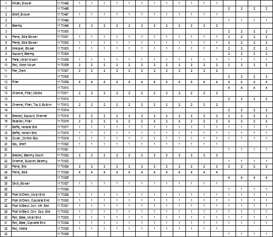
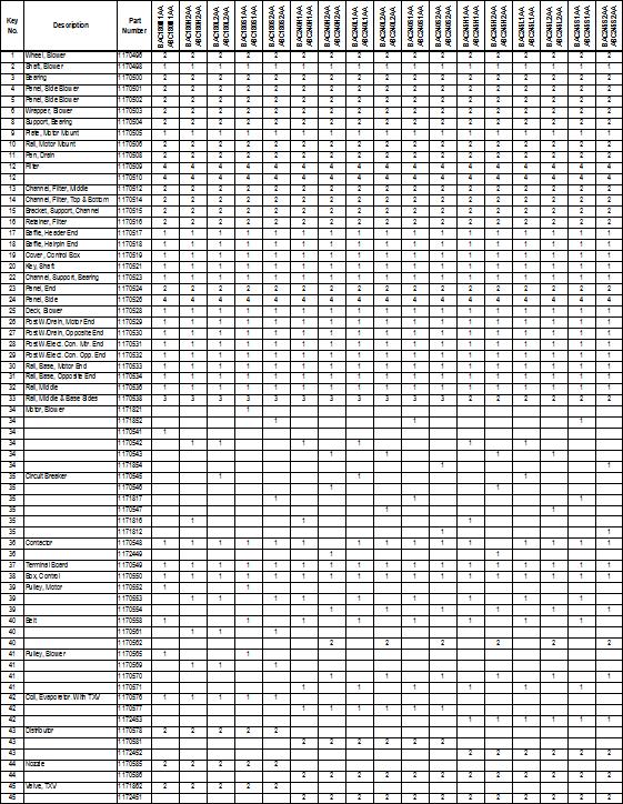
27 PARTS ILLUSTRATION FOR 6 TO 10 TON S Parts List For BAC / ABC Units on page 29 & BHC / HBC Units on page 31 & 32 Illustration for reference only, your unit may differ from the one shown. 27
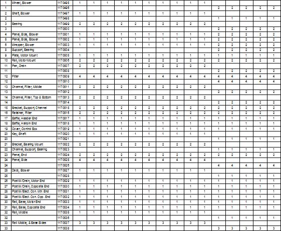
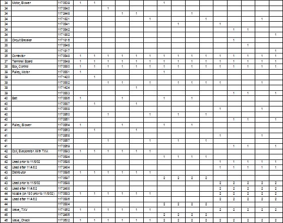
28 PARTS ILLUSTRATION FOR 12 1/2 TO 20 TON S Parts List For BAC / ABC Units on page 29 & BHC / HBC Units on page 31 & 32 Illustration for reference only, your unit may differ from the one shown. 28
29 29
30 30
31 31
32 32
33 33
40 RM/RMS Packaged Air-Handling Units
 ConcepcionCarrier Air conditioning Company Philippines 40 RM/RMS 008034 Packaged AirHandling Units INSTALLATION MANUAL, STARTUP & SERVICE INSTRUCTIONS Contents Page Page Safety Considerations 1 40RM Physical
Installation, Start-Up and Service Instructions
 Installation, Start-Up and Service Instructions - Q- S- Packaged Air-Handling Units 50/60 Hz CONTENTS Page SAFETY CONSIDERATIONS...1 PRE-INSTALLATION...1,2 Moving and Storage...2 Rigging...2 INSTALLATION...
INSTALLATION INSTRUCTIONS FAS/FHS Series, Package Air Handling Units 6 to 25 Ton Air Conditioners 6to20TonHeatPump
 INSTALLATION INSTRUCTIONS FAS/FHS Series, Package Air Handling Units 6 to 25 Ton Air Conditioners 6to20TonHeatPump NOTE: Read the entire instruction manual before starting the installation TABLE OF CONTENTS
INSTALLATION INSTRUCTIONS
 INSTALLATION INSTRUCTIONS FAS/FHS Series, Package Air Handling Units 6 to 25 Ton Air Conditioners 6 to 20 Ton Heat Pump These instructions must be read and understood completely before attempting installation
40LM Hz INSTALLATION, START-UP AND SERVICE INSTRUCTIONS CHILLED WATER FAN COIL UNIT
 Carrier International Sdn. Bhd. Malaysia INSTALLATION, START-UP AND SERVICE INSTRUCTIONS CHILLED WATER FAN COIL UNIT 40LM 120-200 50Hz CONTENTS: Physical Data & Dimension 1-3 Safety Considerations 4 Rigging
Installation, Start -Up and Service Instructions
 PACKAGED AIR -HANDLING S, 60 Hz WITH PURON R (R -410A) REFRIGERANT SIZES 07, 08, 12, 14, 16 Installation, Start -Up and Service Instructions TABLE OF CONTENTS SAFETY CONSIDERATIONS... 1 PRE-INSTALLATION...
Installation, Start---Up and Service Instructions
 Packaged Air---Handling Units 60 Hz With Puron R (R---410A) Refrigerant Sizes 25, 28, 30 Installation, Start---Up and Service Instructions TABLE OF CONTENTS SAFETY CONSIDERATIONS... 1 PRE-INSTALLATION...
Installation, Start-Up and Service Instructions
 38AH044-134 Air-Cooled Condensing Units 50/60 Hz Installation, Start-Up and Service Instructions CONTENTS Page SAFETY CONSIDERATIONS...................... 1 INSTALLATION................................
Installation, Start-Up and Service Instructions
 38AH044-134 Air-Cooled Condensing Units 50/60 Hz Installation, Start-Up and Service Instructions CONTENTS Page SAFETY CONSIDERATIONS...................... 1 INSTALLATION................................
INSTALLATION INSTRUCTIONS TXV Coils for Manufactured Housing EMA
 TXV Coils for Manufactured Housing EMA NOTE: Read the entire instruction manual before starting the installation. SAFETY CONSIDERATIONS Improper installation, adjustment, alteration, service, maintenance,
Models PF1A PF1B PACKAGED AIR-HANDLING UNITS. 6to10Tons. Form No. PDS PF1A.72.1 FEATURES/BENEFITS
 PACKAGED AIR-HANDLING UNITS Models PF1A PF1B 6to10Tons PF1A072-120 PF1B090 FEATURES/BENEFITS Multi-position design can be installed horizontally or vertically without modification Standard sloped drain
INSTALLATION INSTRUCTIONS TXV Horizontal Duct Coils EHD
 TXV Horizontal Duct s EHD These instructions must be read and understood completely before attempting installation. It is important that the Blower and Duct System be properly sized to allow the system
Installation, Start---Up and Service Instructions
 Packaged Air---Handling Units 60 Hz with Puronr (R---410A) Refrigerant Sizes: 07 --- 16 Installation, Start---Up and Service Instructions TABLE OF CONTENTS SAFETY CONSIDERATIONS... 1 PRE-INSTALLATION...
Installation Instructions
 CAELHEAT001A00 - CAELHEAT039A00 AAHC05AHAA - AAHC70ESAA PACKAGED AIR---HANDLING UNITS ELECTRIC HEAT ACCESSORY 6 to 30 TONS (21 to 105 kw) 50/60 Hz Installation Instructions TABLE OF CONTENTS SAFETY CONSIDERATIONS...
INSTALLATION INSTRUCTIONS TXV Horizontal Slab Coils WLSH
 TXV Horizontal Slab Coils WLSH These instructions must be read and understood completely before attempting installation. It is important that the Blower and Duct System be properly sized to allow the system
Installation Instructions
 Installation Instructions Fan Coil Units FG3A NOTE: Read the entire instruction manual before starting the installation. This symbol indicates a change since the last issue. SAFETY CONSIDERATIONS Improper
G Series. G Series Air Coils Installation ti Manual ENCASED/UNCASED AIR COILS. Geothermal/Water Source Heat Pumps R-410A Refrigerant 2-5 Ton
 G Series ENCASED/UNCASED AIR COILS Geothermal/Water Source Heat Pumps R-410A Refrigerant 2- Ton Dimensional Data G Series Air Coils Installation ti Manual Installation Information Maintenance IM1018AG1
MODELS K2EU060A, K4EU090A, & K3EU120A
 AIR COOLED SPLIT-SYSTEM AIR CONDITIONERS INSTALLATION INSTRUCTION Supersedes: 550.23-N2Y (589) 550.23-N2Y (399) MODELS K2EU060A, K4EU090A, & K3EU120A 035-16672 GENERAL These completely assembled 5, 7-1/2
Product Data FEATURES/BENEFITS 524J***H 6 TO 20 TON DIRECT EXPANSION PACKAGED HEAT PUMP AIR -HANDLING UNIT. Indoor air quality features 524J-H 07-12
 524J***H 6 TO 20 TON DIRECT EXPANSION PACKAGED HEAT PUMP AIR -HANDLING Product Data the environmentally sound refrigerant Certified to ISO 9001 524J-H 07-12 524J-H 16-25 C10899 Bryant s versatile packaged
INSTALLATION INSTRUCTIONS TXV Horizontal Duct Coils EHD
 TXV Horizontal Duct s EHD These instructions must be read and understood completely before attempting installation. It is important that the Blower and Duct System be properly sized to allow the system
Installation, Start-Up and Service Instructions
 09AZ091-182 Remote Air-Cooled Condensers 90 to 200 Tons Installation, Start-Up and Service Instructions CONTENTS Page SAFETY CONSIDERATIONS.....................1,2 GENERAL........................................
Installation Instructions
 24AHA4 Performance Series Air Conditioner with Puron Refrigerant 1-1/2 to 5 Nominal Tons Installation Instructions Fig. 1-24AHA4 A07532 SAFETY CONSIDERATIONS Improper installation, adjustment, alteration,
Installation Instructions
 38MHR Outdoor Unit Single Zone Ductless System Sizes 09 to 24 Installation Instructions NOTE: Read the entire instruction manual before starting the installation. NOTE: Images are for illustration purposes
INSTALLATION INSTRUCTIONS TXV Coils EDM, EDD, EDA
 TXV Coils EDM, EDD, EDA These instructions must be read and understood completely before attempting installation. It is important that the Blower and Duct System be properly sized to allow the system to
Installation Instructions Part No , Part No Part No
 Torsion-Flex Motor mount for PSC motors and Rigid-Mount for ECM motors Replacement Kit Cancels: New Installation Instructions Part No. 327752-401, Part No. 327753-401 Part No. 327754-401 IIK-310A-45-11
INSTALLATION INSTRUCTIONS Cased N Coil, Horizontal ENH4X
 INSTALLATION INSTRUCTIONS Cased N Coil, Horizontal ENH4X NOTE: Read the entire instruction manual before starting the installation. TABLE OF CONTENTS PAGE SAFETY CONSIDERATIONS... 1 INTRODUCTION... 1 INSTALLATION...
INSTALLATION INSTRUCTIONS Cased N Coil, Horizontal ENH4X
 INSTALLATION INSTRUCTIONS Cased N Coil, Horizontal ENH4X NOTE: Read the entire instruction manual before starting the installation. TABLE OF CONTENTS PAGE SAFETY CONSIDERATIONS... 1 INTRODUCTION... 1 INSTALLATION...
TABLE OF CONTENTS. NOTE: Read the entire instruction manual before starting the installation. TROUBLESHOOTING... 13
 R 410A Duct Free Split System Air Conditioner and Heat Pump Product Family: DFS4(A/H) System, DFC4(A/H)3 Outdoor, DFF4(A/H)H Indoor NOTE: Read the entire instruction manual before starting the installation.
DLCLRA. INSTALLATION INSTRUCTIONS Outdoor Unit Single Zone Ductless System Sizes 36 to 58 TABLE OF CONTENTS
 DLCLRA INSTALLATION INSTRUCTIONS Outdoor Unit Single Zone Ductless System Sizes 36 to 58 Fig. 1 - Size 36 TABLE OF CONTENTS PAGE SAFETY CONSIDERATIONS... 2 PARTS LIST... 3 SYSTEM REQUIREMENTS... 4 WIRING...
SPLIT-SYSTEM EVAPORATOR BLOWER (AIR COOLED) INSTALLATION INSTRUCTION Supersedes: Nothing N4C-0500
 INSTALLATION INSTRUCTION Supersedes: Nothing N4C-0500") SPLIT-SYSTEM EVAPORATOR BLOWER (AIR COOLED) INSTALLATION INSTRUCTION Supersedes: Nothing 550.23-N4C-0500 MODEL L*BC240 035-16603 GENERAL This 20 ton evaporator blower is designed with two distinct modules
SPLIT-SYSTEM EVAPORATOR BLOWER (AIR COOLED) INSTALLATION INSTRUCTION Supersedes: Nothing 550.23-N4C-0500 MODEL L*BC240 035-16603 GENERAL This 20 ton evaporator blower is designed with two distinct modules
MODELS B1PA024, 030 AND 036
 STELLAR 2000 SINGLE PACKAGE HEAT PUMPS INSTALLATION INSTRUCTION Supersedes: 511.26-N1Y (892) 511.26-N1Y (893) MODELS B1PA024, 030 AND 036 035-11622 GENERAL YORK Model B1PA units are factory assembled heat
Installation Instructions
 PREFERREDT SERIES AIR CONDITIONER WITH PURONR REFRIGERANT 1-1/2 TO 5 NOMINAL TONS Installation Instructions Fig. 1 --- 538A NOTE: Read the entire instruction manual before starting the installation. TABLE
Installation & Maintenance Data IM Contents
 Installation & Maintenance Data IM 254-4 Group: Fan Coil Part Number: 107133000 Date: June 1999 SeasonMaker HiLine Fan-coil Units Type KZZ Contents Inspection..................................... 2 Riser
BAC / BHC SERIES 7-1/2 to 20 Ton Air Handlers
 BAC / SERIES 7-1/2 to 20 Ton Air Handlers 3 Phase, 50 Hz COMMERCIAL SPLIT SYSTEM AIR HANDLER FEATURES CONSTRUCTION Die-formed galvanizedsteel casingsprovide durabilityand structuralintegrity. HIGH STATIC
Brown University Revised August 3, 2012 Facilities Design & Construction Standards SECTION AIR HANDLING UNITS
 SECTION 23 70 00 AIR HANDLING UNITS PART 1. GENERAL 1.1 Section includes air-handling units to 15,000 cfm and accessories. 1.2 Related Sections 1 : A. Division 01 - Brown University Standard for Narragansett
Technical Guide DESCRIPTION CHAMPION SPLIT-SYSTEM EVAPORATOR BLOWER L4EU240A 20 NOMINAL TONS (WORLD 50 HZ) FEATURES XTG-A-0307
 FEATURES XTG-A-0307") DESCRIPTION Technical Guide CHAMPION SPLIT-SYSTEM EVAPORATOR BLOWER L4EU240A 20 NOMINAL TONS (WORLD 50 HZ) This 20 ton evaporator blower is designed with two distinct modules to provide maximum application
DESCRIPTION Technical Guide CHAMPION SPLIT-SYSTEM EVAPORATOR BLOWER L4EU240A 20 NOMINAL TONS (WORLD 50 HZ) This 20 ton evaporator blower is designed with two distinct modules to provide maximum application
Installation Instructions
 CNPVP CNRVP Cased N Coils Upflow --- Downflow Heating --- Cooling Installation Instructions NOTE: Read the entire instruction manual before starting the installation. TABLE OF CONTENTS PAGE SAFETY CONSIDERATIONS...
Product Data. 40RUA/40RUS 6to15TonDirectExpansion 7.5to15TonChilledWater Packaged Air---Handling Units FEATURES/BENEFITS. Indoor air quality features
 A/S 6to15TonDirectExpansion 7.5to15TonChilledWater Packaged Air---Handling Units Product Data Carrier s versatile packaged air-handling units satisfy design requirements with: ---, the environmentally
COMMERCIAL PACKAGED HEAT PUMP AIR HANDLER UNITS, 6 20 TONS
 Product Specifications COMMERCIAL PACKAGED HEAT PUMP AIR HANDLER S, 6 20 TONS BUILT TO LAST, EASY TO INSTALL AND SERVICE Multi position design for horizontal or vertical installation without modification.
TECHNICAL GUIDE SPLIT-SYSTEM AIR-COOLED EVAPORATOR BLOWER 25, 30, 40 & 50 TON LA300, LB360, 480 & 600 (50 Hz) PROVEN PERFORMANCE GENERAL FEATURING
 PROVEN PERFORMANCE GENERAL FEATURING") TECHNICAL GUIDE SPLIT-SYSTEM AIR-COOLED EVAPORATOR BLOWER 25, 30, 40 & 50 TON LA300, LB360, 480 & 600 (50 Hz) PROVEN PERFORMANCE GENERAL The LA/LB line is a flexible performer. LA300, LB360 & 480 can be
TECHNICAL GUIDE SPLIT-SYSTEM AIR-COOLED EVAPORATOR BLOWER 25, 30, 40 & 50 TON LA300, LB360, 480 & 600 (50 Hz) PROVEN PERFORMANCE GENERAL The LA/LB line is a flexible performer. LA300, LB360 & 480 can be
SPLIT-SYSTEM EVAPORATOR BLOWER DESCRIPTION FEATURES L4EU NOMINAL TONS
 036-21096-001 (0101) SPLIT-SYSTEM EVAPORATOR BLOWER L4EU240 20 NOMINAL TONS DESCRIPTION This 20 ton evaporator blower is designed with two distinct modules to provide maximum application flexibility. The
Installation Instructions
 CNPHP Cased N Coils Horizontal Heating --- Cooling NOTE: Read the entire instruction manual before starting the installation. TABLE OF CONTENTS PAGE SAFETY CONSIDERATIONS... 1 INTRODUCTION... 1 INSTALLATION...
RHGN-H: COMMERCIAL AIR HANDLER WITH VARIABLE FREQUENCY DRIVE (VFD) NOMINAL 10 TONS R-410A REFRIGERANT 2-STAGE AIR-FLOW
 NOMINAL 10 TONS R-410A REFRIGERANT 2-STAGE AIR-FLOW") INSTALLATION INSTRUCTIONS RHGN-H: COMMERCIAL AIR HANDLER WITH VARIABLE FREQUENCY DRIVE (VFD) NOMINAL 10 TONS R-410A REFRIGERANT 2-STAGE AIR-FLOW 92-106595-01-00 TABLE OF CONTENTS Introduction.......................................
INSTALLATION INSTRUCTIONS RHGN-H: COMMERCIAL AIR HANDLER WITH VARIABLE FREQUENCY DRIVE (VFD) NOMINAL 10 TONS R-410A REFRIGERANT 2-STAGE AIR-FLOW 92-106595-01-00 TABLE OF CONTENTS Introduction.......................................
Installation Instructions
 CNPVP CNRVP Cased N Coils Upflow --- Downflow Heating --- Cooling Installation Instructions NOTE: Read the entire instruction manual before starting the installation. TABLE OF CONTENTS PAGE SAFETY CONSIDERATIONS...
Technical Guide SUNLINE 2000 DESCRIPTION ACCESSORIES FIELD INSTALLED SPLIT-SYSTEM EVAPORATOR BLOWER K4EU NOMINAL TONS (WORLD 50 HZ)
") Technical Guide SUNLINE 2000 SPLIT-SYSTEM EVAPORATOR BLOWER K4EU180 15 NOMINAL TONS (WORLD 50 HZ) DESCRIPTION These completely assembled units include a well-insulated cabinet, a DX cooling coil with copper
Technical Guide SUNLINE 2000 SPLIT-SYSTEM EVAPORATOR BLOWER K4EU180 15 NOMINAL TONS (WORLD 50 HZ) DESCRIPTION These completely assembled units include a well-insulated cabinet, a DX cooling coil with copper
Installation, Start-Up and Service Instructions
 0TJ06-03S Single-Package Rooftop Units Electric Cooling with Electric Heat Option Installation, Start-Up and Service Instructions CONTENTS SAFETY CONSIDERATIONS. INSTALLATION... Step Rig and Place Unit
INSTALLATION INSTRUCTIONS Cased N Coil, Horizontal ENH4X
 INSTALLATION INSTRUCTIONS Cased N, Horizontal ENH4X NOTE: Read the entire instruction manual before starting the installation. SAFETY CONSIDERATIONS Improper installation, adjustment, alteration, service,
TECHNICAL GUIDE. Description SPLIT-SYSTEM AIR-COOLED CONDENSING UNITS YD360, 480 & THRU 50 NOMINAL TONS YTG-B-0811
 Description These units are completely assembled, piped and wired at the factory to provide one-piece shipment and rigging. Each unit is pressurized with a holding charge of Refrigerant R-410A for storage
INSTALLATION INSTRUCTIONS TXV Coils EBU, EBA
 TXV s EBU, EBA These instructions must be read and understood completely before attempting installation. It is important that the Blower and Duct System be properly sized to allow the system to operate
INSTALLATION INSTRUCTIONS TXV Coils EBD, EBA
 TXV Coils EBD, EBA These instructions must be read and understood completely before attempting installation. It is important that the Blower and Duct System be properly sized to allow the system to operate
INSTALLATION, OPERATION, AND MAINTENANCE MANUAL
 INSTALLATION, OPERATION, AND MAINTENANCE MANUAL TUBE AXIAL FANS BTA, WTA, HTA, DDA The purpose of this manual is to aid in the proper installation and operation of the fans. These instructions are intended
Installation Instructions
 40MAQ High Wall Ductless Split System Sizes 09 to 36 Installation Instructions NOTE: Read the entire instruction manual before starting the installation TABLE OF CONTENTS PAGE SAFETY CONSIDERATIONS 2 PARTS
SECTION AIR HANDLING UNIT
 SECTION 15800 - AIR HANDLING UNIT PART 1 - GENERAL 1.01 RELATED DOCUMENTS A. Basic Requirements: Provisions of Section 15010, BASIC MECHANICAL REQUIREMENTS, and Section 15030, ELECTRICAL REQUIREMENTS FOR
Installation Instructions
 38MPRA Outdoor Unit Single Zone Ductless System Sizes 09 to 12 Installation Instructions NOTES: Read the entire instruction manual before starting the installation. Images are for illustration purposes
INSTALLATION INSTRUCTIONS
 INSTALLATION INSTRUCTIONS Series Units RETAIN THESE INSTRUCTIONS FOR FUTURE REFERENCE WARNING Improper installation, adjustment, alteration, service or maintenance can cause personal injury, loss of life,
TECHNICAL GUIDE GENERAL SPECIFICATIONS COMMERCIAL SPLIT-SYSTEM COOLING UNITS FOUR PIPE SYSTEM OUTDOOR UNIT: INDOOR UNIT:
 GENERAL SPECIFICATIONS OUTDOOR UNIT: TECHNICAL GUIDE COMMERCIAL SPLIT-SYSTEM COOLING UNITS FOUR PIPE SYSTEM MODELS HB 180 & HB 240 MODELS LB 180 & LB 240 15 & 20 NOMINAL TONS 9.7 EER Two independent refrigerant
Installation Instructions
 HUMBBSFP1016 HUMCCSFP1016 Small Fan Powered Humidifier and Humidistat Installation Instructions! WARNING ELECTRICAL SHOCK HAZARD Failure to follow this warning could result in personal injury or death.
INSTALLATION MANUAL (AIR COOLED) SPLIT-SYSTEM AIR CONDITIONER MODEL: LA120 NOTES, CAUTIONS AND WARNINGS SAVE THIS MANUAL B-0203
 SPLIT-SYSTEM AIR CONDITIONER MODEL: LA120 NOTES, CAUTIONS AND WARNINGS SAVE THIS MANUAL B-0203") INSTALLATION MANUAL (AIR COOLED) SPLIT-SYSTEM AIR CONDITIONER CONTENTS NOMENCLATURE............................. 3 GENERAL.................................... 4 SAFETY CONSIDERATIONS.....................
INSTALLATION MANUAL (AIR COOLED) SPLIT-SYSTEM AIR CONDITIONER CONTENTS NOMENCLATURE............................. 3 GENERAL.................................... 4 SAFETY CONSIDERATIONS.....................
Service Step by Step Trouble-Shooting Check-List
 WARNING: Only Data Aire trained technician or experience technicians should be working on Data Aire Equipment. Protect yourself at all times and work safe. Date: Dates at the job site: From: to Job#: Serial#:
CROWN. Boiler Co. Santa-Fe Series. Hydronic Air Handlers INSTALLATION, OPERATION & MAINTENANCE INSTRUCTIONS
 CROWN Boiler Co Santa-Fe Series Hydronic Air Handlers INSTALLATION, OPERATION & MAINTENANCE INSTRUCTIONS These instructions must be affixed on or adjacent to the air handler Models: SAC049A20 SAC059A25
50BY, BL. Ÿà Õ µ µ Èß ËÕߪ Õ» å Single-Package Cooling Units 50BY, BL 50BY, BL
 50BY, BL Ÿà Õ µ µ Èß ËÕߪ Õ» å Single-Package Cooling Units 50BY, BL 50BY, BL Contents Safety Considerations... 4 Danger... 4 Warning... 4 Installation... 5-6 Air Duct Connection... 6 Electrical Wiring...
Installation Instructions
 40MBFQ Floor Console Ductless System Sizes 09 to 58 Installation Instructions TABLE OF CONTENTS PAGE SAFETY CONSIDERATIONS... 2 PARTS LIST... 3 SYSTEM REQUIREMENTS... 4 WIRING... 4 DIMENSIONS... 5 CLEARANCES...
Installation Instructions
 40MBD Ducted Style Ductless System Sizes 09 to 48 Installation Instructions NOTE: Read the entire instruction manual before starting the installation. TABLE OF CONTENTS PAGE SAFETY CONSIDERATIONS... 2
INTRODUCTION. NOTE: Read the entire instruction manual before starting the installation. FIRE, EXPLOSION, ELECTRICAL SHOCK HAZARD
 Installation Instructions NOTE: Read the entire instruction manual before starting the installation. SAFETY CONSIDERATIONS Improper installation, adjustment, alteration, service, maintenance, or use can
INSTALLATION INSTRUCTIONS
 2008 Lennox Industries Inc. Dallas, Texas, USA INSTALLATION INSTRUCTIONS CH33 Series Units EVAPORATOR COILS 505,264M (65484504) 05/08 Supersedes 10/07 Litho U.S.A. RETAIN THESE INSTRUCTIONS FOR FUTURE
Installation Instructions
 Evaporator Coil A Coil --- Cased Multipoise NOTE: Read the entire instruction manual before starting the installation. TABLE OF CONTENTS PAGE SAFETY CONSIDERATIONS... 1 INTRODUCTION... 1 INSTALLATION...
Installation Instructions
 CNPHP Cased N s Horizontal Heating --- Cooling Installation Instructions NOTE: Read the entire instruction manual before starting the installation. TABLE OF CONTENTS PAGE SAFETY CONSIDERATIONS... 1 INTRODUCTION...
INSTALLATION INSTRUCTIONS
 C7BA & C7BH Series Split System Indoor Cased Coils INSTALLATION INSTRUCTIONS IMPORTANT It is your responsibility to know this product better than your customer. This includes being able to install the
Horizontal & Horizontal Quiet Blower Coils
 MANUAL INSTALLATION Horizontal & Horizontal Quiet Blower Coils BCH / BCHQ Series v200 Issue Date: 05/19/15 2015 Price Industries Limited. All rights reserved. TABLE OF CONTENTS Product Overview Safety
FILTERS MANIFOLD CABINET REFRIGERANT CONNECTION LOCATION
 INDEX Introduction....................................... 3 Checking Product Received.......................... 3 Standard Unit Features.............................. 3 Unit Dimensions...................................
Installation, Operating & Maintenance Instructions. Air Handler Models: AH & AV
 Installation, Operating & Maintenance Instructions Air Handler Models: AH & AV Table of Contents Table of Contents... 2 Product Safety... 2 Important Information About Safety Instructions... 2 Receiving...
Installation Instructions
 Installation Instructions Safety Labeling & Rules Installation Requirements Location / Clearances Wiring Air Distribution Ductwork Connections Start-Up Maintenance Hoisting / Rigging PAS090H000 PAS090L000
Product Data FEATURES/BENEFITS. 524J PACKAGED AIR -HANDLING UNITS WITH PURONr REFRIGERANT SIZES 07, 08, 12, 14, 16. Indoor air quality features
 PACKAGED AIR -HANDLING S WITH PURONr REFRIGERANT SIZES,,,, --- Product Data C09311 Bryant s versatile packaged air-handling units satisfy design requirements with: S Multi-position design for horizontal
Installation Instruction
 Installation Instruction Upflow Downflow Heating Cooling CC5A Uncased Coil CD5A Cased Coil SUPPLY RETURN EVAPORATOR COIL DOWNFLOW UPFLOW SUPPLY Fig. 1 Typical Installation of CD5A Cased Coil A96244 NOTE:
SeasonMaker Hi-Line Fan-coil Unit Model HSS S30 through S80
 Installation & Maintenance Data IM 255-6 SeasonMaker Hi-Line Fan-coil Unit Model HSS S30 through S80 Group: Fan coil Part Number: # 106332400 Date: August 2000 Table of Contents Inspection............................................................................
Panel Fan Series Operators Manual (Galvanized and Polymer)
") Panel Fan Series Operators Manual (Galvanized and Polymer) Galvanized Panel Fan with Three Wing Blade IMPORTANT: READ AND SAVE THESE INSTRUCTIONS Read all instructions carefully before attempting to assemble,
Panel Fan Series Operators Manual (Galvanized and Polymer) Galvanized Panel Fan with Three Wing Blade IMPORTANT: READ AND SAVE THESE INSTRUCTIONS Read all instructions carefully before attempting to assemble,
Installation, Operation, and Maintenance Manual
 READ AND SAVE THESE INSTRUCTIONS PART # 538 Model BCF Belt Drive Centrifugal Cabinet Fans Installation, Operation, and Maintenance Manual Please read and save these instructions for future reference. Read
HEATING AND VENTILATION
 SECTION 14-102.04 14-102.04/ 1 2007OC19 DESCRIPTION The heating, ventilation and air conditioning (HVAC) system is designed to optimize passenger comfort. The system regulates interior vehicle atmosphere,
TABLE OF CONTENTS INTRODUCTION. NOTE: Read the entire instruction manual before starting the installation.
 Installation NOTE: Read the entire instruction manual before starting the installation. TABLE OF CONTENTS PAGE SAFETY CONSIDERATIONS... 1 INTRODUCTION... 1 INSTALLATION... 2 Inspect Equipment... 2 Select
Installation Instructions
 40MBFQ Floor Console Ductless System Sizes 09 to 12 Installation Instructions TABLE OF CONTENTS PAGE SAFETY CONSIDERATIONS... 2 PARTS LIST... 3 SYSTEM REQUIREMENTS... 4 DIMENSIONS... 5 CLEARANCES... 5
INSTALLATION INSTRUCTIONS
 INSTALLATION INSTRUCTIONS RHGM COMMERCIAL AIR HANDLERS NOMINAL 7.5 AND 10 TON AIR CONDITIONING FEATURING EARTH-FRIENDLY R-410A REFRIGERANT e arth fr rie endl y r e f r i g e r a n t! Recognize this symbol
Installation Instructions
 Installation Instructions For Cased and Uncased Coils Upflow-Downflow Heating-Cooling CK5A, CK5B Cased CJ5A Uncased SUPPLY RETURN EVAPORATOR COIL DOWNFLOW UPFLOW SUPPLY Fig. 1 Typical Coil Installation
CAS. Product Specifications. COMMERCIAL SPLIT SYSTEMS CONDENSING UNITS R 410A, 6 to 12.5 TONS BUILT TO LAST, EASY TO INSTALL AND SERVICE
 COMMERCIAL SPLIT SYSTEMS CONDENSING UNITS R 410A, 6 to 12.5 TONS BUILT TO LAST, EASY TO INSTALL AND SERVICE CAS Product Specifications Single stage cooling capacity control on all models with Micro channel
Residential Piping and Long Line Guideline
 AC / HP R-410A Refrigerant Systems Single-Stage, Two-Stage and Variable Speed Models Residential Piping and Long Line Guideline TABLE OF CONTENTS Safety Considerations... 2 Definitions... 2 Introduction...
maintenance should only be performed by a trained, qualified person. Consumer service is recommended only for filter replacement.
 AHF / AHK SERIES AIR HANDLING UNITS INSTALLATION GUIDE GENERAL The AHF / AHK series is designed for horizontal recessed installations in a furred down area, above a suspended ceiling or recessed in the
INSTALLATION INSTRUCTIONS
 ,t_2007 Lennox Industries Inc. Dallas, Texas, USA INSTALLATION INSTRUCTIONS CH33 Series Units EVAPORATOR 505,264M (65484504) 10/07 Supersedes 09/06 COILS n _putech blications ical Litho U.S.A. RETAIN THESE
Chromalox. Installation, Operation. Portable Industrial Unit Blower Air Heater Types SDRA and SDRA-RG RENEWAL PARTS IDENTIFICATION
 Chromalox Installation, Operation and RENEWAL PARTS IDENTIFICATION DIVISION SALES REFERENCE DATE (Supersedes PF99-1) AUGUST, 2010 Portable Industrial Unit Blower Air Types SDRA and SDRA-RG SECTION SDRA
WineZone Ceiling Mount Ductless Split 15
 WineZone Ceiling Mount Ductless Split 15 Requires an HVAC technician to install and charge with R-22 refrigerant. Easy to install. Unit plugs into wall outlet. Industrial grade unit for longer life. Indoor
Installation, Start-Up and Service Instructions
 Installation, Start-Up and Service Instructions GEMINI 38ARZ007-012, 38ARS008-012 38ARD012-024, 38AKS014-024 Air-Cooled Condensing Units 50/60 Hz CONTENTS Page SAFETY CONSIDERATIONS...1 INSTALLATION...
Installation Instructions
 Installation Instructions For Cased Coils Upflow-Downflow Heating-Cooling CK5A CK5B SUPPLY RETURN EVAPORATOR COIL DOWNFLOW UPFLOW SUPPLY Fig. 1 Typical Coil Installation NOTE: Read the entire instruction
Installation Instructions
 8GXM / 0GXM Multi---Split High---Wall Duct Free Split System 8GXM --- Size 18k, k, and 0k 0GXM --- Size 9k, 1k, and 18k Installation Instructions NOTE: Read the entire instruction manual before starting
PACKAGE AIR CONDITIONER
 PACKAGE AIR CONDITIONER FORM NO. ATZ-206 TZAA- HIGH EFFICIENCY SERIES NOMINAL SIZE 10 TON [35.2 kw] 10 TON MODEL [35.2 kw] This product is shipped with a nitrogen holding charge that must be vented prior
Duct Heaters volts/1 phase volts/3 phase volts/3 phases volts/3 phases. Flange Type Duct Heater.
 Duct Heaters Synheat duct heaters come in various sizes and dimensions to fit any compartment. There are three types of duct heaters available: open coil, tubular element or finned tubular heating elements
Product Data. Features/Benefits. 50HS Single-Package Heat Pump Units 50 Hz
 Product Data 50HS Single-Package Heat Pump Units 50 Hz Nominal: 7 to 18 kw (2 to 5 Tons) Single-Package Heat Pump for Manufactured Housing/Residential and Light Commercial use. Features/Benefits One-piece
K*ES120 DESCRIPTION TECHNICAL GUIDE SPLIT-SYSTEM EVAPORATOR BLOWERS 10 NOMINAL TONS EER 8.5 ACCESSORIES FIELD INSTALLED TABLE 1: ARI RATINGS*
 TECHNICAL GUIDE SPLIT-SYSTEM EVAPORATOR BLOWERS K*ES120 10 NOMINAL TONS EER 8.5 DESCRIPTION These completely assembled dual circuit evaporator blower units include a well-insulated cabinet, a DX cooling
INSTALLATION INSTRUCTIONS
 INSTALLATION INSTRUCTIONS C7BA Series Split System Indoor Cased Coils IMPORTANT ATTENTION INSTALLERS: It is your responsibility to know this product better than your customer. This includes being able
SPLIT-SYSTEM HEAT PUMPS 50 AND 60 HZ DESCRIPTION
 SPLIT-SYSTEM HEAT PUMPS 50 AND 60 HZ E3FB090/E1FB120/F3EH090 & 120 7-1/2 & 10 NOMINAL TONS (60 HZ) 7 & 9 NOMINAL TONS (50 HZ) (9.0-9.2 EER) 208/230/460 VOLT ONLY 208/230 VOLT ONLY DESCRIPTION YORK has
Installation, Operation and Service Instructions
 90MA/MU Single-Package Marine Cooling Units Installation, Operation and Service Instructions SAFETY CONSIDERATIONS The 90MA/MU Units are designed to provide safe and reliable service when operated within
Component. Maintenance. Manual Z SERIES. Evaporator Assembly
 Component Maintenance Manual with Illustrated Parts List for Z21-701-SERIES Evaporator Assembly 1 of 16 Record of Revision REVISION ISSUE POSTED NO: DATE DATE INSERTED BY: 2 of 16 List of Effective Pages
Cased Aluminum "Convertible" Coils 4TXCB003CC3HC** 4TXCB004CC3HC** 4TXCC005CC3HC** 4TXCC006CC3HC**
 18- AH44D1-4 Cased Aluminum "Convertible" Coils 4TXCB003CC3HC 4TXCB004CC3HC 4TXCC005CC3HC 4TXCC006CC3HC 4TXCC007CC3HC 4TXCC008CC3HC 4TXCD009CC3HC 4TXCD010CC3HC May be "A" or "B" ALL phases of this installation