700KV Van de Graaf Generator
|
|
|
- Erin Owens
- 6 years ago
- Views:
Transcription

1 700KV Van de Graaf Generator By Frederick W. Graff Frederick W. Graff Page 1


2 700KV VDG KIT Frederick W. Graff Page 2
3 Table of Contents Introduction and Materials 4 How a VDG Works 5-6 Tower Construction 7-8 Attaching the Tower 9-10 Motor and Wiring 11 Rollers Machining the Dome Static Shield & Alignment Operation 16 Trouble Shooting 17 Maintenance 18 Safety 18 Demos 19 Frederick W. Graff Page 3

4 Introduction: Welcome to perhaps what will be your first VDG build. This manual is designed to give you a very straight forward streamlined set of instructions so that you will be finished and shocking your friends in no time. To start the build, below you will find a list of materials, tools and general adhesives that are necessary for completion. I encourage that you take your time to ensure a kit that will operate at its maximum performance. During the process of constructing the VDG, there are a few things that are imperative to be mindful of. The first is to never get oil on any of the parts, primarily the belt and rollers, because this will hinder the device from producing a charge. Secondly, never clean the VDG with acetone or other alcohols because it will react and crack the acrylic, furthermore, acrylic is very fragile so be extremely cautious while handling. With these tips in mind, let s get busy. Tools: Drill and Bits Sand paper (fine grit) Dremel Cut Off Wheel Screw Driver Needle Nose Pliers Grinding Bit Razor Blade Sharpie Measuring Tape Materials: Gorilla Super Glue 5 minutes 2 ton epoxy(osh) Fishing String Paint of your choice Frederick W. Graff Page 4
5 How a VDG Works: The VDG works by taking electrons from the bottom grounded comb and transferring them to the top comb, where they are then distributed to a dome where they are trapped and accumulated to produce a very large electric field. The heart of this charging process is dictated by two physical principles. The first principle is that opposite charges attract and like charges repel such as in magnets. The second physical principle is that many objects develop either a positive or negative charge when rubbed. This process of charging is often done on a daily basis such as when you rub your feet on the carpet and accidently shock the cat or when you pull you clothes from the drier and feel the clinging sensation from the charge that built upon the clothes while drying. As found in the triboelectric series, some materials develop a stronger + or charge than others. With these physical principles in mind, let s now look more closely at how the VDG dome receives the charge that makes our hair stand up. When the latex belt runs across the bottom nylon roller it develops positive charge which then produces a positive electric field. The free roaming electrons on the bottom metal grounded comb begin to feel the attraction from the positive electric field, causing them to fling toward the roller. However, since insulating latex belt is between the comb and the roller, the electrons get stuck to the latex belt surface, where they are then transported to the top to be flung right back off. During this process the top roller develops a negative charge that emits a negative electric field. As the electrons on the latex belt begin to approach this roller, they start to feel its repulsive negative charge, where they are flung to the closest conductor they can find, which so happens to be the top comb. The electrons are then pushed through the metal support system, to the stainless steel Frederick W. Graff Page 5
6 discharge dome where they accumulate to produce the hair standing electric field. As the belt rounds the top roller, now approaching the bottom, it will have a neutral charge due to the excess electrons expelled to the dome. If the top roller can develop a large enough negative charge, it will produce a returning positive charge belts, which in turn will be advantageous to attracting even more electrons from the bottom comb. The dome is one of the most crucial parts of the VDG, which accounts for at least 80% the generator s final output voltage. So that a maximum voltage can be achieved, it is essential to understand conceptually how the electrons interact with the metal sphere. Once the electrons make it to the dome, they are now roaming around and cramming against each other due to their individual repulsive electric fields. Essentially they are looking for a way out, which consist of any edge or point on the surface that offers a path of least resistance. By referring to the illustration, there is a high concentration of electrons located at the discharge sphere s bottom edge because this is a region where the electrons feel the lowest resistant and will try to prematurely leak off (leakage), hence creating a lower voltage. To prevent this from occurring, the dome has an insulation that lines the bottom edging. Not only will the electrons try to leak off from the bottom location, but from any protruding scratch or even dust/dirt particles. Because insulators become conductors at high voltages, mostly any material on the dome such as dust or debris could create a point of leakage. If there are no points of leakage present, the electrons will build to such great numbers that they will arc to surrounding objects or even down the acrylic tower. Just wait and you will see! Frederick W. Graff Page 6


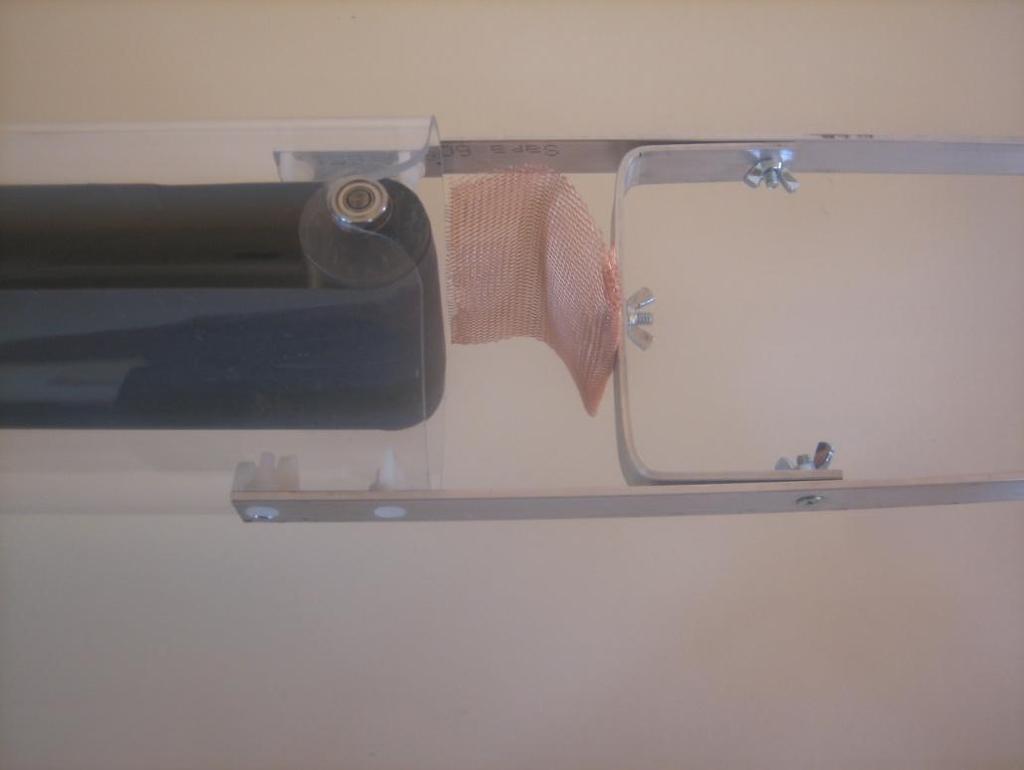
7 Tower Construction Illustrations Frederick W. Graff Page 7


8 Tower and Support System Construction Cont: (45 minutes) The aluminum support systems will now come 90% complete for you. The final step in preparation is to construct the center brace. To do so, drill a 15/64 inch hole at each end and in the center as indicated on the 9 inch stock bar. Next, bend 90 degree angles at the indicated location on the bar to create the pivotal structure as seen in the illustrations. Be careful not to over bend the aluminum as it will become fragile and break. Once complete, bolt the center brace on using the machine screws and wing nuts. The aluminum support system must be attached on the outside of the tower using the nylon hardware. The metallic comb is place on using one of the machine blots along with a fend washer and wing nut. Once the belt and rollers are placed on the system as directed in the later sections, cut the top and bottom combs so that they are slightly touching the rollers. During operation, the combs should rest about ¼ from the rollers. This is done by placing a slight crimp on the combs to pull them back. Crucial Design Notes 1. It is crucial that the aluminum support system stays on the outside of the tower otherwise electrons will leak back on to the belt, hence not allowing the system to build a maximum charge. 2. The discharge comb should not drag on the belt while running. Keep it between.5-2 cm away, however the closer the better. Frederick W. Graff Page 8
 Warning: I recommend only those with electrical experience pursue this part of the build. Please proceed with caution.")
9 3. If you have an aluminum sheet comb, make sure you cut slits into it such that there are points to create ion jets to spray charge onto the belts. Motor, Motor Cover, & Wiring: (30 minutes) Warning: I recommend only those with electrical experience pursue this part of the build. Please proceed with caution. The wiring for the new VDG s with the external speed control consist of connecting the power cord to the motor using the blue wire connectors and directing the green ground lead to the central prong. The ground lead is used for supplying charge to the bottom roller brass comb. When finished, place the black wire cover over the connections and direct the power cord to the external speed control. The red wire will connect between the two ¼ bolts with wing nuts and then to the bottom comb. This second grounding location was added to provide access to create a positively charged source. To fully utilize the positively charged source, you will need to disconnect the green ground wire during operation. Frederick W. Graff Page 9


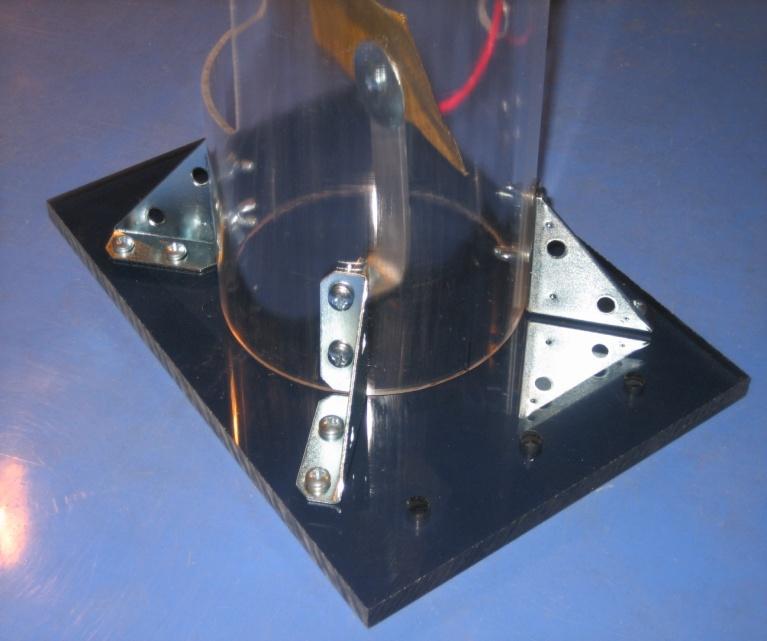
10 Motor Connection: The motor is connected using the acrylic plate and hex bolts to act as a spacer. The bottom of the motor will use two machine screws to attach the acrylic motor plate. These bolts will need two washers so that the screw does not go too far into the motor and interfere with the rotating parts. Once the motor is connected, the longer 1 inch machine screws will mount the plate to the base using hex bolts as the spacers. Frederick W. Graff Page 10


11 Motor Cover: As seen in the photos bellow, the motor cover is braced by using the L-brackets and machine screws with the wing nuts. All holes will be pre-drilled. Frederick W. Graff Page 11

12 Rollers and Combs: (30 minutes) The rollers will arrive as a solid Delrin or PVC and nylon roller. To assemble these rollers, place the axles, pulleys, and bearings in the order as seen in the illustration above. The pulley should easily fit on the axle, however the bearings are designed for a tighter fit, therefore you may need to minimally sand down the part of the axle that the bearings attaches to. Ideally the bearings should require a slight amount of pressing force to fit onto the axle. The larger axle usually is the most difficult to press on because the bearing has to slide over 1 inch of axle. As easy and safe way of pressing this bearing on is to significantly sand the axle so that the bearings can slide down with minimal force. Then use Loctite or a two part epoxy to glue it in place. If bearings need to be replace, the best resource is from ebay for ¼ inch flanged bearging with a 5/8 OD. Frederick W. Graff Page 12

 These axles will need to be pressed in to the rollers using a vice press or very gently tapped in with a rubber hammer.")

13 Prepping the axles When sanding the axle it is important to NOT sand that part of the axle that fits into the roller because it will no longer hold a press fit in the roller. To sand the axle, just place it in a drill and run a piece of sand paper over the axle while spinning. Do this for only a few seconds and test the bearing on the axle. If too loose of a fit is made, place a small amount of two part epoxy on the axle to hold the bearing. To complete rollers, first prepare all the axles as seen in the illustration above. (The newer model will not be using the shaft collars) These axles will need to be pressed in to the rollers using a vice press or very gently tapped in with a rubber hammer. In the process of pressing in the axles, you will want to check that you do press them in too far by placing roller in the tower roller insertion holes. Ideally, these should only have snug fit to alleviate unnecessary axial stress on the bearings. The rollers are designed to have high friction coatings that extensively enhance the VDG s performance. The PVC or Delrin roller uses a Pliobond coating which may be purchased at ACE Hardware if worn off over time. The nylon roller comes with a 100% wool felt that may be attached using super glue and then wrapping it with nylon fishing string. Frederick W. Graff Page 13

14 Machining the Dome: The newer VDG sphere will come machined and will only need the insulation applied. When connecting the insulation, be sure to press it on as tight as possible so that there is no gap where the two ends meet. Should there be a gap, use a two part epoxy to cover it. Once the insulation is attached, place the sphere on the VDG tubing with the aluminum support system already connected. With the sphere resting on the aluminum support system, place a mark on the tubing where the bottom of the sphere. This is the location where the foam edging will be placed in order to fill the gap between the insulation and the tubing. To secure the edging it is advisable to place a wrapping of electrical tape around it. Once the edging is on, place the aluminum tape just above the edging. The aluminum tape is used to prevent leakage from the bottom of the sphere and will allow potentials to reach over 700KV. Frederick W. Graff Page 14

15 Do you want an extra 70,000 Volts plus? Wrap electrical tape around the bottom of the dome to further insulate the edge. This will enable device to produce much larger arcs and reach 800 to 900 kv potentials when ran at full speed. Approach with absolute caution! Crucial Design Notes: 1) Be sure to clean the inside of the dome otherwise metal shrapnel will fall to the belt and roller system and interfere with the charging process. 2) The black insulating strip must be placed on very tightly with no metal edging showing Mending the Belt Material: (15 minutes) To mend the belt material, you will have to cut with a sharp pair of scissors a 45 degree lap joint and then mend it with Gorilla Super Glue only. The best way to apply the super glue is to over lay the lap joint and then pick up one side only, apply the glue, spread it using q-tip and then press the sides together with pressure for 30 seconds. Do the same for the other half. Gorilla Super Glue makes an awesome bond, so good that if the belt accidentally sticks to any part of itself, it will make an immediate bond, therefore, take precautions that no other parts of the belt come in contact with the glue. Frederick W. Graff Page 15
16 Roller and Belt Alignment: (5 minutes) To adjust the VDG so that the belt runs properly on the rollers you may need to make a few adjustments to the top open roller notches. To assess if this adjustment is necessary, connect the belt and rollers to the VDG tower and hand crank the system. If the belt favors the closed notch side, you will need to lightly sand down the open notch side and vice versa for the other. During this process, only a very small about of acrylic will need to be sanded off to complete the alignment. Frederick W. Graff Page 16
17 VDG Operation Instructions WARNING: Prior to starting, make sure the speed control is at least 6 feet from the VDG. Never touch the speed control while next to the generator otherwise it will destroy the speed control. Setting Up and Operating the VDG: 1) When bolting in the aluminum dome support system and tower, only slightly snug the bolt otherwise you will crack the acrylic. 2) Before placing on the belt and rollers, rewash the belt and both rollers using dish soap. Try to avoid getting water on the bearings. When finished, dry a paper towel. 3) To assemble the belt and rollers, it is easiest to first place the belt on the top roller and then proceed to attach the bottom roller. Allow for about.5 to 2 cm of spacing between the rollers and combs. A VDG with a black bottom wool roller will cause a negative charged dome and a clear acrylic bottom roller will cause a positive charge dome. 4) Turn the generator on without the dome attached and feel the top support system for sparks. If there are no sparks, blow a hair dryer through the bottom opening until it develops a charge. This may take up to 10 minutes. Under optimal conditions, there should be a continuous stream of sparks consisting of 2 inch arcs coming from the support system when touched. Though 95% of the time the VDG will start right up, if it is still lagging, rewash the belt and rollers and allow is to run for about 10 minutes. You will find the more you use the VDG, the stronger it will operate. 5) Gently place the dome on top of the support system and insert the nylon bolt through the dome. This nylon bolt only hold the dome in place. 6) The sparks should average about 12 inches, with max sparks at 24 inches. If you are not getting 12 inch arcs, it could be due to a variety of reasons such as high humidity levels or sharp pointed grounded objects in the vicinity that create ion jets and pull the electrons from the dome, hindering the VDG from building a charge. Please refer to trouble shooting. 7) If vibrations occur within the system you may need to tighten the tension between the roller bearing and tower by either slightly prying out the axles or adjusting the shaft collars. Frederick W. Graff Page 17
18 Trouble Shooting: 1) Problem: Humid day. This will decrease the voltage by half. That is why they say we have good VDG weather and bad VDG weather. Solution: Blow a hair dryer through the bottom of the VDG roller entrance hole. 2) Problem: Dust particles on dome that cause leakage. Solution: Clean the dome after each hour of use. Even small dust particles will cause points of leakage. To see the points of leakage, run the VDG with the lights out and look for small blue ion jets. Brush the ion jet away and the VDG will produce rather large arcs. Be very careful while trying this technique 3) Problem: High mineral content in water used to wash the belt. This will completely shut the VDG off. Solution: Try washing the system with distilled water which may be purchased at the grocery store. 4) Problem: Oil on belt and rollers. This will shut the VDG off. Solution: Wash the top and bottom roller with soapy water. 5) Problem: Belt is not dry enough after washing. This will shut the VDG off. Solution: Blow hot air up through the bottom of the tower while running. 6) Problem: Dusty belt. This will deter the charge a little. Solution: Clean the belt with soapy water. 7) Problem: Pointed metal objects around the VDG will cause it leak. Solution: The VDG cannot be around pointed objects because they will prematurely pull charge from the dome and not allow it to build to its maximum potential. Keep the VDG located in open space. 8) Problem: Belt begins to rub on the combs at very high speeds. Frederick W. Graff Page 18
19 Solution: Once the belt develops a large amount of ware, it will loosen and possibly brush the combs during operation. This will indicate that it is time to change the belt. These belts are made from a latex material and will break down in UV light, therefore when finished using the VDG, take off the belt and place it in a dark location. These belts should last a very long time if stored correctly. VDG Maintenance: 1) Do not allow the belt to come in contact with the combs during operation in order to maximize the belts life 2) Latex will oxidize when in the presence of ozone or UV light. The ozone is inevitable due to the voltage produced however the UV will inflict a significant amount of damage over time, therefore always store the belt in a dark place when not in use. 3) Never clean with alcohol or acetone due to sever cracking of the acrylic. 4) The VDG belt and rollers may be cleaned with dish soap and water. Try to avoid water contact with the bearings. 5) All parts of the VDG charging system (dome, belt and rollers, and tower should be cleaned every 2hours of run time. VDG Safety: 1) VDG s should not be used around people with heart condition or pacemakers. 2) Be careful not to make items that will act as high voltage capacitors. The current from the VDG s are fairly safe, however when the current is allowed to be stored at such high voltages they can become lethal. 3) Larger VDGs will produce welts from prolong exposure to arcs. 4) Keep away from all electronics and do not use in the same circuit that is used for other electronics 5) Operate in well ventilated areas due to the ozone produced. 6) Avoid making human chains. 7) Keep speed control away from VDG Warranty and Replacement Parts: Warranty: Physics Playground generators and high voltage equipment is covered under a one year warranty accept for static belts and speed controls (or AC to DC converter power supplies) Sign of rough use such as dropping, over tightening hardware, and exposure to Frederick W. Graff Page 19
20 caustic chemicals will dismiss the equipment from eligibility of the warranty. Prior to sending the replacement part, the buyer must a photo of the damaged part to frederickgraff@hotmail.com for verification. All replacement parts will be shipped within 4 business days. Consumable Parts: Please visit Physics playground for replacement parts. Both belt material and pre-made belts will be sold on the website. For those who wish to mend their own belts, the belt sizes are listed below. 300KV and 350KV DC Powered VDGs: (2 in x 35 in) 350KV High Current VDG: (3.5 in x 35 in) 500KV and 700KV High Current VDGs: (4.5 in x 47 inch) Experimenter Ideas: 1) Insulate yourself and touch the VDG while pointing at various objects in the room to place a charge on. When done to a chandelier it will cause arcs within the chain. 2) Insulate and charge yourself with 700,000V and then step off of the insulated material and experience the feeling of your body just electrically shut off from the field. 3) Wrap the bottom roller with a metallic coating and force feed it with a 15,000V charge to induce higher currents. These VDG are designed to do so. (Very Dangerous) 4) Wrap a balloon in foil and then hang it from a string attached to the ceiling so that it can touch the dome. Turn on the VDG and watch the outcome. 5) Take two pie pans and attach a positive and negative lead from the VDG to each pan. Next place small foil leaves between the pans or string. Very cool to see! Frederick W. Graff Page 20
 Charging Lynden Jar and high voltage beer cup capacitors (Dangerous!!!) 8) Place pie pans on the generator and watch them fly. 9) Static electricity motors and ion jets.")
21 6) Bring fluorescent tubes near the VDG. This makes a great visual for examining electric fields. The tube will begin to glow at 5 feet away. 7) Charging Lynden Jar and high voltage beer cup capacitors (Dangerous!!!) 8) Place pie pans on the generator and watch them fly. 9) Static electricity motors and ion jets. 10) Just insulate yourself to feel your entire body light up from being immersed in the 700,000V electric field. ABSOLUTELY AWESOME!!! However, if someone touches you...ouch! This seems to be my students favorite thing to do especially with the x-large 770KV VDG where they will develop 8 inch arcs coming off of them when approached. Yes, this is a crowd pleaser!!! Warning: All of these demos are extremely fun and exciting to do, however as in every situation when experimenting, please consider all dimensions of safety. Use at your own risk. Frederick W. Graff Page 21
400KV Van de Graaff Generator Kit Builders Manual
 400KV Van de Graaff Generator Kit Builders Manual 400KV Design Photos Introduction: Welcome to perhaps what will be your first VDG kit. This manual is designed to give you a very straight forward and streamlined
300KV Van de Graaff Generator Kit Builders Manual
 300KV Van de Graaff Generator Kit Builders Manual www.physicsplayground.com 300KV Design Photos (Black) 300KV Design (Orange) Introduction: Welcome to perhaps what will be your first VDG kit. This manual
600KV Van de Graaff Generator High Current Model
 600KV Van de Graaff Generator High Current Model www.physicsplayground.com Frederick W. Graff 2012 Page 1 600KV Kit Model Frederick W. Graff 2012 Page 2 Table of Contents Introduction and Materials 4 How
Physics Playground. Van de Graaff Generator Instructions. About Physics Playground. How a Van de Graaf Generator Works
 Van de Graaff Generator Instructions About Physics Playground HV Supplier for: 400KV DC or AC Powered VDG (built /kit) 450 KV High Current VDG (built / kit) 600 KV High Current VDG (built / kit) 700 KV
Static Electricity: Bending and Floating
 Static Electricity: Bending and Floating Week 3A Objectives: In this lesson students will learn: About the force of static electricity How electricity relates to our everyday life Intro to electrons Background:
2 Installation Instructions For Vari-Fan Ceiling Fans Installation Instructions For Vari-Fan Ceiling Fans 11
 Installation Instructions For Installation Instructions For Vari-Fan Ceiling Fans Vari-Fan Ceiling Fans Installation Instructions For Vari-Fan Ceiling Fans Vari-Fan Ceiling Fans DC powered fans designed
Van de Graaff Generator. Spinner Package Demonstration Guide
 Van de Graaff Generator Spinner Package Demonstration Guide Demonstrations for the Science First Van de Graaff generator and its included accessories. Teaching with Van de Graaff The Van de Graaff generator
Vari-Cyclone Ceiling Fans
 Installation Instructions For Vari-Cyclone Ceiling Fans Installation Instructions For Vari-Cyclone Ceiling Fans Vari-Cyclone Ceiling Fans DC powered fans designed to operate on 12 or 24 vdc only! Toll
MNEFDD54 & MNBCDD54 GALVANIZED WALL FANS Installation, Operation, and Maintenance Instructions
 FARM PRODUCTS DIVISION MEMBER OF AMCA AMERICAN COOLAIR CORPORATION P.O. BOX 2300 JACKSONVILLE, FLORIDA 32203 PHONE (904) 389-3646 FAX (904) 387-3449 E-MAIL - fans@coolair.com MNEFDD54 & MNBCDD54 GALVANIZED
Vari-Fan Ceiling Fans
 Installation Instructions For Vari-Fan Ceiling Fans Installation Instructions For Vari-Fan Ceiling Fans Vari-Fan Ceiling Fans DC powered fans designed to operate on 12 or 24 vdc only! Toll free: 1 (877)
Installation Instructions. For the 18 Built-In Dishwasher and Front Color Panels
 Installation Instructions For the 18 Built-In Dishwasher and Front Color Panels Printed in USA 154232102 Before You Begin DO NOT INSTALL DISHWASHER UNTIL YOU HAVE READ ALL INSTRUCTIONS. FOR YOUR SAFETY,
Installation Instructions
 GE Consumer & Industrial Appliances Installation Instructions Junction Box Cover Within this user bag, you will find a junction box cover and a #10 hex head screw used to attach the junction box cover
5 SAFE EXPERIMENTS USING A VAN DE GRAAFF! INSPIRING TOMORROW S SCIENTISTS THROUGH PRACTICAL SCIENCE
 5 SAFE EXPERIMENTS USING A VAN DE GRAAFF! INSPIRING TOMORROW S SCIENTISTS THROUGH PRACTICAL SCIENCE INTRODUCTION THE VAN DE GRAAFF GENERATOR IS AMONGST THE MOST RECOGNISABLE PIECES OF APPARATUS IN THE
Installation Instructions
 GE Consumer & Industrial Appliances Installation Instructions Junction Box Cover Within this user bag, you will find a junction box cover and a #10 hex head screw used to attach the junction box cover
User s Manual and Operating Instructions
 User s Manual and Operating Instructions Model Numbers: PT-18W-DDF-A, PT-20F-DDF-A, PT-20S-DDF, PT-24O-DDF, PT-24-DDF, PT-24-DDF-F, PT-30-DDF, PT-30P-DDF-A, PT-30P-DDF-AF READ AND SAVE THESE INSTRUCTIONS
Ceiling Fan Installation Instructions
 OWNER S MANUAL Ceiling Fan Installation Instructions Total fan weight For 3TF24XX Series Fans READ AND SAVE THESE INSTRUCTIONS QUALITY CEILING FANS Installation 1. 2. 3. 4. 5. 6. 7. 8. 9. 10. 11. 12. 13.
Table of Contents. What to Expect with. Mounting Options. Tools Needed. Preparation. Wiring. Downrod.
 Table of Contents www.casablancafanco.com What to Expect with Your Installation Congratulations on purchasing your new Casablanca ceiling fan! It will provide comfort and performance in your home or office
FD Heavy Duty Feeder for FD 280 Tabbing System
 FD 280-10 Heavy Duty Feeder for FD 280 Tabbing System Operator Manual 8/2011 First Edition TABLE OF CONTENTS 1. INTRODUCTION... 1 1.1 Feeder Description... 1 1.2 Items Included... 1 1.3 Operating Manual
READ AND SAVE THESE INSTRUCTIONS
 READ AND SAVE THESE INSTRUCTIONS CEILING FAN INSTALLATION AND OPERATION INSTRUCTION FAN RATING AC 120V. 60Hz UL LISTED MODEL: AC-552OD WEIGHT OF FAN: 6.82 KGS 1. TOOLS AND MATERIALS REQUIRED Philips screw
Table of Contents. What to Expect with. Mounting Options. Tools Needed
 Table of Contents www.hunterfan.com What to Expect with Your Installation Congratulations on purchasing your new Hunter ceiling fan! It will provide comfort and performance in your home or office for many
Standard Downrod for ceilings 8-10 feet high. Longer Downrod for ceilings 10 feet or higher
 Table of Contents www.casablancafanco.com To register your fan, please visit: www.casablancafanco.com/register What to Expect with Your Installation Save your receipt for proof of purchase. Ceiling Bracket??
INLET DAMPER WALL FAN UNIT
 FARM PRODUCTS DIVISION MEMBER OF AMCA AMERICAN COOLAIR CORPORATION P.O. BOX 2300 JACKSONVILLE, FLORIDA 32203 PHONE (904) 389-3646 FAX (904) 387-3449 E-MAIL - agfans@coolair.com INLET DAMPER WALL FAN UNIT
Installation Instructions
 Installation Instructions Built-In Dishwasher If you have questions, call 800-GECARES or visit our website at: www.geappliances.com BEFORE YOU BEGIN Read these instructions completely and carefully. IMPORTANT
User s Manual and Operating Instructions
 User s Manual and Operating Instructions Model Numbers: CL-30P-DDF, CL-20F-DDF, CL-24O-DDF, CL-30-DDF READ AND SAVE THESE INSTRUCTIONS IMPORTANT: Read and understand all of the directions in this manual
Table of Contents. What to Expect with. Tools Needed. Mounting Options. Blades
 Table of Contents 1.888.830.1326 Ceiling Bracket 30 inches Ladder Downrod 3 Wiring 10 Operation, Maintenance & Cleaning Light Kit 11 Troubleshooting??? 17 15 1 13 5 Blades 9 Switch Housing 12 Canopy 6
SHRIMP CUTTER AND DEVEINER
 SHRIMP CUTTER AND DEVEINER 1 Prawnto Shrimp Machine of Texas Co., Inc. CONGRATULATIONS You have just purchased one of the most exciting and serviceable machines you have ever had in you operation. With
Built-In Dishwasher. Installation Instructions. BEFORE YOU BEGIN Read these instructions completely and carefully. IMPORTANT The dishwasher MUST be
 Installation Instructions Built-In Dishwasher If you have questions, call 800.GE.CARES (800.432.2737) or visit our website at: www.ge.com BEFORE YOU BEGIN Read these instructions completely and carefully.
Installation Instructions
 Wood Blinds Installation Instructions Heartland Woods Heartland Woods w/ Continuum *Click on any page to return to the Table of Contents* Heartland Woods Wood Blinds Mounting Inside or Outside Window Frame
TCUT10UL 2.5 HP 10 Tile Saw Assembly & Operating Instructions
 TCUT10UL 2.5 HP 10 Tile Saw Assembly & Operating Instructions READ ALL INSTRUCTIONS AND WARNINGS BEFORE USING THIS PRODUCT. This manual provides important information on proper operation and maintenance.
Installation Instructions Built-In Dishwasher
 RINSE CHINA CRYSTAL SPEED CYCLE NORMAL WASH COOK WARE SELECTIONS ANTI BACTERIA START RESET ENHANCEMENTS DELAY HOURS ADDED HEAT PRE WASH HEATED DRY TO LOCK CONTROLS PRESS HEATED DRY FOR 3 SECONDS GE Consumer
NEPTUNE Steam Room Installation Instructions
 NEPTUNE Steam Room Installation Instructions IMPORTANT Please read carefully the following instructions before installing your shower cabin. If you have any questions on this shower cabin installation
Table of Contents. What to Expect with. Tools Needed. Mounting Options. Blades
 www.hunterfan.com Table of Contents Ceiling Bracket 30 inches Downrod Ladder 3 Wiring Operation, Maintenance & Cleaning Light Kit 11 Troubleshooting??? 16 15 1 12 10 9 5 Blades Canopy 6 4 PÁGINA 2 7 feet
π H-2268 SANITAIRE UPRIGHT VACUUM SAFETY uline.com
 π H-2268 SANITAIRE UPRIGHT VACUUM 1-800-295-5510 uline.com SAFETY PAGE 1 OF 7 NOTE: When using an electrical appliance, basic precautions should always be followed, including the following: READ ALL INSTRUCTIONS
TRUSTY PRODUCTS, INC.
 TRUSTY PRODUCTS, INC. 137 S. 8 th Avenue, #D, City of Industry, CA 91746 Tel: (626) 333-2221 Fax: (626) 333-2466 D.C. 12V CEILING FAN INSTALLATION INSTRUCTIONS V002-RC QUESTIONS OR CONCERNS CONTACT TRUSTY
5COM52XXD Series Fan. Owner s Guide and Installation Manual. UL Model NO. : 5COM52XXD
 Owner s Guide and Installation Manual 5COM52XXD Series Fan UL Model NO. : 5COM52XXD Attach sales receipt to this card and retain as your proof of purchase DATE OF PURCHASE: MODEL NUMBER: RETAILER NAME:
DAVIS PACKAGING. TD-362 Dual Roll Console Reference Guide.
 DAVIS PACKAGING www.davispackaging.net E-mail: contact@davispackaging.net TD-362 Dual Roll Console Reference Guide SPECIFICATIONS Overall Dimensions: Working Height: Power Requirement: Wattage: Unit Weight:
Table of Contents. What to Expect with. Mounting Options. Tools Needed. Wall Control
 Table of Contents www.casablancafanco.com What to Expect with Your Installation Congratulations on purchasing your new Casablanca ceiling fan! It will provide comfort and performance in your home or office
Water Distiller Service Manual
 Water Distiller Service Manual Water Distiller Service Manual L70478WT 2008 Regal Ware, Inc. Table of Contents RECOMMENDED TOOLS... 2 GENERAL INSPECTION...3 BOILING CHAMBER TROUBLESHOOTING & REPAIRS Description...
INSTALLATION, OPERATION, AND MAINTENANCE MANUAL
 INSTALLATION, OPERATION, AND MAINTENANCE MANUAL TUBE AXIAL FANS BTA, WTA, HTA, DDA The purpose of this manual is to aid in the proper installation and operation of the fans. These instructions are intended
Table of Contents. Ceiling Bracket Installation
 Table of Contents What to Expect with Your Installation Congratulations on purchasing your new Casablanca ceiling fan! It will provide comfort and performance in your home or office for many years. This
Aquapeutics GENERAL INSTALLATION GUIDE. Toll Free Customer Service line 1 (800)
") Aquapeutics GENERAL INSTALLATION GUIDE Toll Free Customer Service line 1 (800) 290-6812 Thank you for choosing an Aquapeutics product. Please read the following guide in its entirety before assembling
Aquapeutics GENERAL INSTALLATION GUIDE Toll Free Customer Service line 1 (800) 290-6812 Thank you for choosing an Aquapeutics product. Please read the following guide in its entirety before assembling
English BT3600
 www.blackanddecker.com 3 English BT3600 FIG. 1 FIG. 2 150mm BENCH GRINDER BT3600 GENERAL SAFETY RULES WARNING: Read all instructions. Failure to follow all instructions listed below may result in electric
Installation Instructions
 Installation Instructions Built-In Dishwasher If you have questions, call 800-944-9400(US),800-245-8352(Canada)or visit our website at: www.frigidaire.com BEFORE YOU BEGIN Read these instructions completely
CEILING FAN OWNER S MANUAL
 CEILING FAN OWNER S MANUAL VERA CRUZ 5/04 GENERAL INSTALLATION & OPERATION INSTRUCTIONS IMPORTANT SAFEGUARDS: 1. To ensure the success of the installation, be sure to read the instructions and review the
DATE OF PURCHASE: RETAILER NAME: MODEL NUMBER: RETAILER ADDRESS:
 Owner s Guide and Installation Manual 3TF24XX Series Fan UL Model No. : AC-536 Attach sales receipt to this card and retain as your proof of purchase DATE OF PURCHASE: RETAILER NAME: MODEL NUMBER: RETAILER
Ceiling Fan Installation Instructions
 OWNER S MANUAL Ceiling Fan Installation Instructions For 5SH54XXD-L Series Fans READ AND SAVE THESE INSTRUCTIONS Total fan weight with light kit 1. 2. 3. 4. 5. 6. 7. 8. 9. 10. 11. 12. 13. 14. 15. 16. 17.
INSTALLATION MANUAL FOR MODELS: TERAZZA, TRACCIO, MILANO, CERRATO
 INSTALLATION MANUAL FOR MODELS: TERAZZA, TRACCIO, MILANO, CERRATO TABLE OF CONTENTS ROOM SPECIFICATIONS ELECTRICAL SPECIFICATIONS PLUMBING SPECIFICATIONS TECHNICAL SPECIFICATIONS INTRODUCTION ASSEMBLY
Table of Contents What to Expect with Your Installation. Tools Needed. Wall Control
 Table of Contents Congratulations on purchasing your new Casablanca ceiling fan! It will provide comfort and performance in your home or office for many years. This installation and operation manual contains
Graaf Generator. Making rollers: Assembly
 Graaff GENERATOR Contents Assembly... 2 Safety... 9 Operating the Generator... 9 Operation... 10 Experiments & Demonstrations... 11 Cleaning & Maintenance... 13 The Van de Graaff Machine Ancestors... 17
BG6UL. 6 Inch Bench Grinder Assembly & Operating Instructions
 BG6UL 6 Inch Bench Grinder Assembly & Operating Instructions READ ALL INSTRUCTIONS AND WARNINGS BEFORE USING THIS PRODUCT. SAVE THESE INSTRUCTIONS FOR FUTURE REFERENCE. This manual provides important information
HE120, HE160 Humidifier Installation Kit
 HE120, HE160 Humidifier Installation Kit INSTALLATION INSTRUCTIONS WELCOME To the comfortable world of humidified air. When you use your Honeywell humidifier, you notice that your skin is not as dry, and
Installation Instructions Built-In Dishwasher
 GE Consumer & Industrial Appliances Installation Instructions Built-In Dishwasher If you have questions, call 800.GE.CARES (800.432.2737) or visit our website at: www.ge.com BEFORE YOU BEGIN Read these
C-IV 60 CEILING FAN READ AND SAVE THESE INSTRUCTIONS. FAN RATING AC 120V. 60Hz
 C-IV 60 CEILING FAN READ AND SAVE THESE INSTRUCTIONS FAN RATING AC 120V. 60Hz Please do not use any electric or battery powered tools in the assembly and installation of this or any Matthews Fan Company
Installation Instructions
 Installation Instructions For the 18" Built-In Dishwasher Sears, Roebuck and Co. Sears Canada, Inc. Hoffman Estates, IL 60179 U.S.A. Toronto, Ontario, Canada M5B 2B8 154435201 Before You Begin DO NOT INSTALL
CEILING FAN OWNER S MANUAL
 CEILING FAN OWNER S MANUAL LX SERIES 5/04 WARNING: Read and follow these instructions carefully and be mindful of all warnings shown throughout. GENERAL INSTALLATION & OPERATION INSTRUCTIONS IMPORTANT
SERVICE MANUAL TWIN TUB WASHING MACHINE PWM6010M PWM8010PM PWM1010PM PWM1210PM
 SERVICE MAUAL TWI TUB WASHIG MACHIE PWM6010M PWM8010PM PWM1010PM PWM1210PM + + TABLE OF COTEES 1.SAFET PRECAUTIO 1. Safety precaution 2. Introduction of product 2.1 ame of parts 3.Trouble shooting 3.1
Table of Contents What to Expect with. Tools Needed. Mounting Options. Wiring. Downrod. Canopy.
 Table of Contents Congratulations on purchasing your new Hunter ceiling fan! It will provide comfort and performance in your home or office for many years. This installation and operation manual contains
AP Air Ion Counter Instructions
 AP Air Ion Counter Instructions Standard 2 million ions/cm 3 version- The 6 m long ground cord should be used to connect the meter to earth ground for most types of measurements - - especially if you are
52 CEILING FAN READ AND SAVE THESE INSTRUCTIONS FAN RATING AC 120V.
 Irene 52 CEILING FAN READ AND SAVE THESE INSTRUCTIONS FAN RATING AC 120V. 60Hz TABLE OF CONTENTS Tools and Materials Required... 1 Package Contents... 1 Safety Rules... 2 Mounting Options... 3 Hanging
Dishwasher Installation Instructions DW 24XT/DW 24XV
 Dishwasher Installation Instructions DW 24XT/DW 24XV Installation Instructions Dishwasher BEFORE YOU BEGIN Read these instructions completely and carefully. IMPORTANT Observe all governing codes and ordinances.
Installation Instructions
 Installation Instructions Self-Cleaning Radiant Electric Drop-In Range JDP47, JD968, JD900 If you have questions, call 1.800.GE.CARES or visit our website at: ge.com Before You Begin Read these instructions
Installation and Operation Manual For Hunter Ceiling Fans
 Installation and Operation Manual For Hunter Ceiling Fans 1 2 CONGRATULATIONS! Your new Hunter ceiling fan is an addition to your home or office that will provide comfort and performance for many years.
Owner s Guide and Installation Manual
 For Your Records and Warranty Assistance For reference, also attach your receipt or a copy of your receipt to the manual. Model Name Type 2 Models Owner s Guide and Installation Manual Model No. Catalog
Dual Suction System Pro-Lite
 Dual Suction System Pro-Lite INSTRUCTION MANUAL Model CFR51EC CFR LIMITED WARRANTY CFR will repair or exchange parts for your vacuum in the event of a manufacturing defect as follows: PARTS: New or comparable
Nilfisk Inc Winnetka Avenue North Minneapolis, MN REV.03( ) VF80189
 VF80189") Nilfisk Inc. 9435 Winnetka Avenue North Minneapolis, MN 55445 www.usviper.com REV.03(05-) VF8089 SAFETY PRECAUTIONS This machine is intended for commercial use. It is constructed for use in an indoor
Nilfisk Inc. 9435 Winnetka Avenue North Minneapolis, MN 55445 www.usviper.com REV.03(05-) VF8089 SAFETY PRECAUTIONS This machine is intended for commercial use. It is constructed for use in an indoor
Table of Contents What to Expect with Your Installation. Tools Needed. Motor Housing.
 Table of Contents Congratulations on purchasing your new Casablanca ceiling fan! It will provide comfort and performance in your home or office for many years. This installation and operation manual contains
ELECTRIC FLAT PANEL FIREPLACE HEATER
 ELECTRIC FLAT PANEL FIREPLACE HEATER Model Numbers: 80-2000A-42 OWNER S MANUAL AC 120V 60Hz 1500W WARNING Read and understand this entire owner s manual, including all safety information, before plugging
OPERATION INSTRUCTION
 IONIZING AIR BLOWER PC OPERATION INSTRUCTION Thank you for purchasing this PC Ionizing Air Blower. It is designed to eliminate the static electricity from a charged object. Please read this manual before
MAINTENANCE MANUAL TAIYO SEIKI CO., LTD.
 MAINTENANCE MANUAL TAIYO SEIKI CO., LTD. Introduction This Maintenance Manual explains how to replace and adjust the major components of the Automatic Taping Machine when required in daily operation.
Oreck Edge - Upright Tune-Up & Service Guide 02/26/2010
 The Oreck Manufacturing Company Oreck Edge - Upright Tune-Up & Service Guide 02/26/2010 Compiled by Clark DeNoble 1 Table of Contents Electrical Page 3 Tune-Up Evaluate Page 4 Clean Page 4 Replace Page
Table of Contents. What to Expect with. Preparation. Tools Needed. Wiring. Hanging the Fan. Blades.
 www.hunterfan.com Table of Contents Tools Needed Preparation Ceiling Bracket 30 inches Hanging the Fan 3 4 Wiring 5 9 Ladder 2 7 feet We are proud of our work and appreciate the opportunity to supply you
INSTALLATION MANUAL FOR MODELS: SOVANNA, BREZZA, TERRACINA, VENADO
 INSTALLATION MANUAL FOR MODELS: SOVANNA, BREZZA, TERRACINA, VENADO 1 STRADA, TERCERA, SEDONA, MARVIN STEAM SHOWERS SPECIFICATION SHEET 87.8 30 24 SOVANNA, VENADO, BREZZA, TERRACINA STEAM SHOWER UNIT DIMENSIONS
Installation Instructions
 Installation Instructions Electric Drop-In Range JDS28, JDP39 Questions? Call 800.GE.CARES (800.432.2737) or Visit our Website at: ge.com BEFORE YOU BEGIN Read these instructions carefully and completely.
GRIND PRO DUAL OR DISC SANDER. Operator Manual
 GRIND PRO DUAL OR DISC SANDER Operator Manual 2 GRIND PRO DUAL OR DISC ORTHO-SANDER INTRODUCTION The Grind Pro Dual or Disc Sander is a compact, durable machine designed for fast, complete finishing work.
Installation Instructions
 PAGE 1 Installation Instructions Important information about your new a/c system. Please read the following directions prior to installing this a/c system. PN: CK6772-1CHPU 1967-1972 Chevy PU A/C Kit Contact
STATIC MERRY-GO-ROUND
 Curriculum topics: Static Electricity Experimental Variables Momentum Electrically Charged vs. Uncharged STATIC MERRY-GO-ROUND Make and power a version of the first electric motor! Subject: Physical Science
TSOKOS Section 5-1 Van de Graaff Generator Demonstration
 IB PHYSICS Name: DEVIL PHYSICS Period: Date: BADDEST CLASS ON CAMPUS TSOKOS Section 5-1 Van de Graaff Generator Demonstration 1. Read the attached article on Van de Graaff generators. 2. The Van de Graaff
NSS STANDARD-SPEED FLOOR MACHINES
 OPERATION MANUAL NSS STANDARD-SPEED FLOOR MACHINES IMPORTANT SAFETY INSTRUCTIONS Read all instructions before using or servicing machine. WARNING: Fire or explosion hazard. NEVER use with flammable or
XPB10-LAP TWIN TUB WASHING MACHINE
 SERVICE MANUAL XPB10-LAP TWIN TUB WASHING MACHINE WD-8888-89 HAIER AMERICA TRADING, LLC www.haieramerica.com WD-8888-89 CONTENTS 1.Contents 1 2. Features 2 3. Specifications 3 4. Safety precautions 4 5.
Table of Contents What to Expect with Your Installation. Tools Needed. Wall Control
 Table of Contents Congratulations on purchasing your new Casablanca ceiling fan! It will provide comfort and performance in your home or office for many years. This installation and operation manual contains
54" Skye. Instruction Manual Customer Service :30 AM to 5:00 PM EST, Monday - Friday A Kichler Decor ceiling fan
 54" Skye TM 300167 A Kichler Decor ceiling fan Includes wall mount control system Kichler Lighting 7711 East Pleasant Valley Road P.O. Box 318010 Cleveland, Ohio 44131-8010 Instruction Manual Customer
568X, 587X, 588X Series
 Please read and save this Repair Parts Manual. Read this manual and the General Operating Instructions carefully before attempting to assemble, install, operate or maintain the product described. Protect
GALAXY FLOOR MACHINE
 OPERATION MANUAL GALAXY FLOOR MACHINE IMPORTANT SAFETY INSTRUCTIONS WARNING: Failure to observe these instructions can cause personal injury to machine operator or bystanders. WARNING: Shock or electrocution
Product instruction manual Easymount Wide Format Laminators
 Product instruction manual Easymount Wide Format Laminators The Easymount has been designed to be user friendly, however we strongly recommend you take a few minutes to read through this manual to ensure
Table of Contents. What to Expect with Your Installation. Tools Needed. Mounting Options. Ceiling Bracket. Wiring.
 www.hunterfan.com Table of Contents What to Expect with Your Installation Congratulations on purchasing your new Hunter ceiling fan! It will provide comfort and performance in your home or office for many
OWNER S MANUAL ELECTRIC FLAT PANEL FIREPLACE. AC V 60Hz. Model# : /60 - Built-in & Wall Mounted Electric Fireplace WARNING CAUTION
 ELECTRIC FLAT PANEL FIREPLACE Model# :80017 OWNER S MANUAL 50/60 - Built-in & Wall Mounted Electric Fireplace AC 110-120V 60Hz WARNING Read and understand this entire owner s manual, including all safety
Table of Contents. What to Expect with. Tools Needed. Mounting Options. Preparation. Downrod. Maintenance.
 www.hunterfan.com Table of Contents What to Expect with Your Installation Congratulations on purchasing your new Hunter ceiling fan! It will provide comfort and performance in your home or ofice for many
Service Manual. Model Number: Compact Fireplace DF203A DF2006. UL Part Number to 800
 Service Manual Model Number: Compact Fireplace DF203A DF2006 UL Part Number 6901860100 to 800 IMPORTANT SAFETY INFORMATION: Always read this manual first before attempting to service this fireplace. For
SNC1P Electricity Practice Test
 SNC1P Electricity Practice Test Multiple Choice Identify the choice that best completes the statement or answers the question. 1. Which type of energy comes from the flow of charged particles? a. chemical
60" Lyndon Patio. Instruction Manual Customer Service :30 AM to 5:00 PM EST, Monday - Friday A Kichler Decor ceiling fan
 60" Lyndon Patio TM 310140 A Kichler Decor ceiling fan Includes wall mount control system Kichler Lighting 7711 East Pleasant Valley Road P.O. Box 318010 Cleveland, Ohio 44131-8010 Instruction Manual Customer
HydroCycle Vertical Aeroponic Systems
 HydroCycle Vertical Aeroponic Systems 2018 Growers Supply All Rights Reserved. Reproduction is prohibited without permission. 113700 4' Vertical System (24 Grow Sites) Revision date: 01.10.18 1 Important
π H-2549 SANITAIRE UPRIGHT VACUUM SAFETY uline.com
 π H-2549 SANITAIRE UPRIGHT VACUUM 1-800-295-5510 uline.com SAFETY PAGE 1 OF 5 NOTE: When using an electrical appliance, basic precautions should always be followed, including the following: READ ALL INSTRUCTIONS
USSC LLC 4 ONE LLC FIELD MODIFICATION INSTRUCTIONS
 and Retrofit of G2E Quick Release Cushion Upholstery 1 OF 32 A 1.0 PURPOSE: To replace both Back and Cushion Upholstery on the G2E seats. 2.0 Tools Required: 2.1 1/2 Socket and Wrench 2.2 5/8 Socket 2.3
60" Tulle PatioTM. Instruction Manual. A Kichler Select ceiling fan
 60" Tulle PatioTM A Kichler Select ceiling fan cul Certified for Wet Location Kichler Lighting 7711 East Pleasant Valley Road P.O. Box 318010 Cleveland, Ohio 44131-8010 Customer Service 866.558.5706 8:30
STATIC ELIMINATOR I443A INSTRUCTION MANUAL
 STATIC ELIMINATOR I443A INSTRUCTION MANUAL Thank you for purchasing a Static Eliminator. It is designed to eliminate the static charge from a charged object. Please read this manual before operating the
WAILEA OWNER S MANUAL
 WAILEA OWNER S MANUAL The blades in each pack are matched for equal weight to assure smooth fan operation. If more than one fan is being installed, be careful not to mix blades from different cartons.
5LCM52XX Series Fan. Owner s Guide and Installation Manual. UL Model NO. : AC-552AL
 Owner s Guide and Installation Manual 5LCM52XX Series Fan UL Model NO. : AC-552AL Attach sales receipt to this card and retain as your proof of purchase DATE OF PURCHASE: MODEL NUMBER: RETAILER NAME: RETAILER
BG8SS. 8 Inch Slow Speed Bench Grinder with LED Lights Assembly & Operating Instructions
 BG8SS 8 Inch Slow Speed Bench Grinder with LED Lights Assembly & Operating Instructions READ ALL INSTRUCTIONS AND WARNINGS BEFORE USING THIS PRODUCT. SAVE THESE INSTRUCTIONS FOR FUTURE REFERENCE. This
Cable Drum Machine. Operation Manual 40 SERIES. Cleans 2" to 4" lines up to 75' N O T F O R R O O T S
 Cable Drum Machine Operation Manual 40 SERIES Cleans 2" to 4" lines up to 75' Used For: Sinks, Showers & Floor Drains N O T F O R R O O T S WARNING - Read All Instructions, When Using Electric Tools, Basic
User Guide Ted's Tumbler Model 2
 User Guide Ted's Tumbler Model 2 CAUTION: READ ALL INSTRUCTIONS BEFORE USING TUMBLER. Changes from Version 1: Version 2 is essentially identical to version 1 except for the addition of belt guards and