_en SP 5080 OPERATING MANUAL CHANNEL BALING PRESS SP Keep this instruction for future use!
|
|
|
- Gyles Dean
- 6 years ago
- Views:
Transcription


1 _en SP 5080 OPERATING MANUAL CHANNEL BALING PRESS SP 5080 Keep this instruction for future use!
2 HSM GmbH + Co.KG, Austrasse 1-9, Frickingen / Germany Tel Fax info@hsm.eu _en 04/2013
3 Contents Nameplate 6 Foreword 7 1 Safety Notes on safety "Work safety" symbol "Notice" symbol Classifi cation of hazards Danger Warning Caution Notes on work safety Proper use Inspecting the safety devices Technical data Power requirement and fuse rate KP 80 Combined press FA Shredder Operating conditions Accessories SP 5080 explanatory diagram Machine dimensions Preparations General instructions Siting the machine Supply connections Settings Transporting the baling press Transport to another application site Transporting the shredder Assembling the shredder Assembling the shredder press combination / _en 3
4 4 Commissioning Baling press controls Accessing the SERVICE menu Set-up mode Pressure plate forward-backward / door lock open-close To exit set-up mode To display / clear the daily bale meter To display the total bale meter To display the service hours meter To set the user language To display the error memory System Shredder control panel Display: Baling press not in automatic mode Display: Status of the baling press Initial start-up Using the machine Fit the plastic bag and start the machine Ejecting and bagging the bale Malfunctions of the baling press Error numbers Malfunctions of the shredder Overload due to paper jam Electric motor overheats Emergency stop activated Oil reservoir empty Stopping the machine Outdoor use Inspection and maintenance work Notes on maintenance Maintenance of the combined press Changing the hydraulic fl uid / venting fi lter Lubricating the movable parts Maintenance of the FA shredder Lubricating the drive chains and synchronized wheels (2 x per year) Retighten the feed belt Check the directional stability of the feed belt Check the feed belt for wear Emptying the collecting tray _en 04/2013
5 6 Storage 52 7 Disposal instructions Disposal verifi cation form Using and ordering spare parts Customer service address Electrical circuit diagrams KP 80 hydraulic diagram EC declaration of conformity 57 04/ _en 5

6 Nameplate HSM GmbH+Co.KG Austrasse 1-9 D Frickingen Germany MODELL MASCH.-NR.: SERIEN - NR.: PRESSKRAFT: kn SPANNUNG: V Hz LEISTUNG: kw BAUJAHR: NENNSTROM: A The machine number is specifi ed on the nameplate of the baling press, shown above. Guarantee claims and inquiries cannot be processed if you do not quote the machine number. Please therefore enter this number into the grey fi eld of the nameplate immediately after receipt of the baling press _en 04/2013
7 Foreword This Operating Manual informs you in detail about the start-up and maintenance of your new baling press. It also contains notes on safety which must be observed. To a great extent, the performance of your baling press depends on its proper application and thorough maintenance. You should carefully read this Operating Manual and the notes on safety and always keep them safe at hand. You can thus prevent accidents, maintain your guarantee claims against the manufacturer and always have an operative baling press. HSM GmbH + Co. KG permanently aspire to improve their products. They reserve the right to perform any changes and modifi cations which are deemed necessary. However, this does not imply the obligation for a subsequent modifi cation of already delivered machines. Technical modifi cations as compared to the representations and statements in this Operating Manual which become necessary to improve the baling press are reserved. This Operating Manual is intended for staff installing, operating and servicing the baling press. It includes technical specifi cations and drawings which must not be copied, distributed or used for competitive purposes or given to third parties completely or in part. Please contact your local dealer if you still have questions after having read this Operating Manual. 04/ _en 7
8 1 Safety 1.1 Notes on safety "Work safety" symbol "Notice" symbol This symbol marks all work safety notes in this Operating Manual which endanger the health or life of people. Please pay attention to this symbol and exercise particular care in such cases. Please also forward all work safety notes to other users. Apart from the instructions in this manual, you must also follow generally applicable safety and accident prevention regulations.. This symbol marks information in this manual which requires particular attention so that guidelines, regulations, instructions and correct working procedures are followed and damage to or ruin of the machine and/or other equipment prevented. 1.2 Classification of hazards Danger identifi es an immediate danger. If not avoided, it will result in death or severe injuries (crippling) Warning identifi es a possibly dangerous situation. If not avoided, it could result in death or severe injuries Caution identifi es a possibly dangerous situation. If not avoided, it could result in light or minor injuries. Is also used for warnings concerning damage to material _en 04/2013
9 1.3 Notes on work safety Please pay particular attention to the following notes on work safety: The SP 5080 shredder press combination has been safety-tested by an accredited testing station. Nevertheless, incorrect operation and misuse can result in: the health or life of the operator the machine and other valuable equipment the effi cient operation of the shredder The SP 5080 shredder press combination has been built with the most up-to-date technology. However, the machine can be dangerous if improperly used, even by trainedstaff, or if used for purposes other than those for which it was designed. The operation of the shredder press combination is always subject to local safety and accident prevention regulations. The employer must observe and comply with the minimum safety and health requirementsfor the use of work equipment by workers at work. Machinery Directive 2009/104/EC The shredder press combination may not be operated by anyone under 16 years of age. All those charged with installation, assembly, disassembly, start-up, operation, inspection, maintenance or repair of the baling press must have fi rst read and fully understood the entire operating manual, paying particular attention to the Safety section. The shredder press combination may only be operated, serviced and repaired by authorised, trained staff. These staff must have been given special instructions on any dangers which may possibly arise. Areas of personal responsibility for installation, assembly, re-assembly, set-up, operation and maintenance must be clearly defi ned and strictly adhered to, in order to avoid confusion which might compromise safety. When carrying out installation, disassembly, re-assembly, maintenance, operation, adjustment and maintenance work always observe the shut-down procedures described in the operating manual. Never perform this kind of work on the machine unless it is fully shut down. Before performing such tasks make sure the drives and additional mechanisms of the baling press cannot be switched on unintentionally. Turn the main switch to the 0 position and secure it. Pull out the power plug. Before starting the machine after repairs, make sure all protective devices are in place. 04/ _en 9
10 Do not carry out any tasks which may endanger your safety while operating the machine. Any changes which take place and could impair safety should be reported immediately. Put the machine out of operation until the damage is rectifi ed. Always make sure the machine is in perfect condition before you switch it on. Make sure the area around the machine is clean and safe. Unauthorised modifi cations and changes to the machine are strictly prohibited. Protective devices may not be removed or otherwise rendered inoperative. No work on the machine which is not part of its normal operation may be performed while the machine is still running. Never open doors and fl aps before the machine has been shut down. Note the instruction plate. Test the protective measures installed after any electrical or repair work. No platforms or other raised surfaces may be placed near the shredder press combination if they encroach on the specifi ed safety clearances. Connecting cables must be laid in such a way that they cannot be tripped over. Only persons with the appropriate skills and experience in hydraulics may carry out work on the hydraulic equipment. All lines, pipes and bolted joints must be regularly inspected for looseness, leaks and visible damage. Any damage must be repaired immediately. Escaping oil can cause fi re and injury Any parts of the system and hydraulic pressure lines that need to be opened must be depressurised according to the assembly instructions before commencing repair work _en 04/2013
11 1.4 Proper use The SP 5080 shredder press combination is intended solely for shredding and pressing paper and cardboard. The robust cutting unit is unaffected by staples and paper clips and is even suitable for the destruction of whole volumes of fi les and folders. Excluding other types of materials. Mode of operation: The above mentioned material is fed into the Shredder. The shredded material falls through the discharge chute of the shredder directly into the hopper of the press. The press cycle is initiated by a light barrier in the hopper when it has been fi lled to a certain level. The press ram is extended and pushes the material into the press chamber, where it is compacted. The shredder continues to run during the press cycle. As soon as the bale has reached a certain length, it has to be ejected into a gusseted bag. Thereafter pressing can continue. Any other use is considered improper. The manufacturer accepts no liability for damage resulting from improper use - the operator carries sole responsibility for such use. Proper use also includes carrying out installation, assembly, disassembly, start-up, operation and maintenance work as prescribed by the manufacturer. The baling press may only be operated, serviced and repaired by staff who are familiar with these regulations and aware of the dangers. The shredder press combination may only be operated by authorised, trained staff. Do not carry out any tasks which may endanger your safety while operating the machine. The relevant accident prevention regulations and any other generally recognised health and safety standards must also be observed. 04/ _en 11
12 1.5 Inspecting the safety devices Check the safety devices: at the start of every work shift (when operation was interrupted) at least once a week when the operation is interrupted after each maintenance or repair Check the safety devices for: specifi ed condition specifi ed position safe attachment specifi ed function Use the following checklist for your inspection. Correct any defects before starting the machine! If any defects arise during operation stop the machine immediately and ensure that the defect is corrected. Do not modify or remove any of the protective devices. Do not deactivate any of the protective devices by modifying the machine. Modifi cations to the machine are prohibited for safety reasons! _en 04/2013
 2.")
13 Checklist for inspecting the safety devices Use the following list for your inspection of the safety devices. Photocopy it for regular inspections. Tick off the boxes if the check was successful. Do not start the machine until you have checked every point. 1. All protective plates must be mounted and fi rmly bolted on. (see picture) 2. The control cabinet must be closed and the Lightning symbol warning sign affi xed to it. 3. Check the safety switch on the hopper. The safety switch switches the shredder press combination off immediately and prevents it from being switched on again when the inspection fl ap is opened. Try this function out! 04/ _en 13


14 4. When you press the emergency stop switch bar whilst the machine is running, the shredder and baling press must switch off immediately. The machines can only be switched on again once you have pulled out the switch bar. Try this function out! Ein-Mann-Bedienung One-man operation Un seul opérateur 5. The safety sticker One-man operation must be fi xed to the shredder. 6. The Safety instruction symbol sticker must be fi xed to the shredder. Inspected Date... Signature _en 04/2013
15 2 Technical data 2.1 Power requirement and fuse rate Security level 2-3 Security level 4 Voltage 3 x 400 V / 50 Hz 3 x 400 V / 50 Hz Net 3P+N+PE 3P+N+PE Power 11,5 kw 13,5 kw Fuse 32 A 32 A Rated current 32 A 32 A 2.2 KP 80 Combined press Weight Size (L x W x H) approx. 600 kg 2335 x 945 x 1400 mm Press data Pressing force Specifi c pressing force Cycle time when idling (theoretical) Bale size (L x W x H) Bale weight (depending on material)* 80 kn 30 N/cm² s 800 x 570 x 490 mm kg Motor data Rated power P n 4,0 kw Operating voltage U 3 x 400 V / 50 Hz Rated current l n 8,3 A Protection class IP 55 Hydraulics Operating pressure 210 bar Pump Discharge Q 19,5 l/min Cylinder Pressing cylinder Ø 70/50 x 1000 mm Oil tank Capacity Oil grade 20 l multi-grade oil (DIN T3) ISO viscosity grade HVLP 22 Noise emission The sound pressure level does not exceed 80 db(a) *)Bale weight : The bale weight varies depending on the type, humidity and condition of the compressed material and on bale length / height. 04/ _en 15
16 2.3 FA Shredder Cutting type Particle cut Cutting size (mm) 10,5 x ,5 x x ,9 x 1,5 Security level DIN Security level DIN P-2/O-2/T-2/E-2 2 P-3/O-2/T-3/E-2 2 P-3/O-2/T-3/E-2 3 P-5/O-4/T-5/E-4/F-2 4 A4 (sheet) cutting performance 70 g/m g/m Throughput security level 4 Intake width Cutting speed Power supply kg/h 500 mm 210 mm/s 3 x 400 V, 50 Hz Rated power motor 7,5 kw 5,5 + 4 kw Rated current at rated 27 A 31 A cutting capacity Plug Fuse Industrial plug Typ "gl" 35 Ampere automatic cutout Ambient conditions for transport, storage and operation: Temperature Relative humidity Altitude above sea level K or C / 32 Ampere -10 C bis +40 C max. 90 %, without condensation max m Dimenstions W x D x H 1170 x 1795 x 1795 mm Weight 790 kg 920 kg Sound pressure level 75 db(a) Shredded material container volume 530 l (2 x 265 l) 2.4 Operating conditions Operating temperature - 10 C + 40 C Operating humidity max. 90%, without-condensing Operating altitude max m above sea level 2.5 Accessories PE gusseted bag Order no.: /490 x 1400 x 0,075 mm _en 04/2013


17 2.6 SP 5080 explanatory diagram Press control cabinet 2 Press control panel 3 Press inspection fl ap 4 Safety flap door lock 5 Counter plate 6 Door lock 7 Press chamber 8 Hydraulic cover FA Shredder 10 Loading table 11 Shredder control panel 12 Emergency stop switch bar 13 Feed belt 14 Swivel roller with brake Pressing cylinder 16 Press motor 17 Venting fi lter 18 Hydraulic tank 19 Shredder inspection flap 20 Oil reservoir opening 04/ _en 17
18 2.7 Machine dimensions 2 x1,5 kn 2 x1,5 kn 2 x2,3 kn 2 x2,3 kn _en 04/2013
19 3 Preparations 3.1 General instructions We strongly recommend that installation work on the baling press should be carried out by trained HSM engineers. We accept no liability for damage resulting from incorrect installation. If you do perform installation tasks yourself, make sure you have read and fully understood the entire operating manual before you start. 3.2 Siting the machine When deciding where to install the machine (e.g. planning by the customer) make sure there is enough space around the machine so that assembly and repair work can be carried out without obstruction. Upstream and downstream machines are to be arranged accordingly. The installation on the prepared foundation must be carried out in such a way that the shredder press combination is level. The shredder press combination may only be operated in dry rooms. At temperatures below 0 C and above 30 C respectively, use different hydraulic oil that has a suitable viscosity for the baling press or upgrade the tank heater/oil cooler. 3.3 Supply connections Power is supplied via the central control cabinet of the baling press. The control cabinet has a power connection cable with a CEE plug. The installation site must have a CEE 5x32A/6H power socket with an appropriate fuse. (see Technical data ) 3.4 Settings In general, all the components have been installed, and the electrical and hydraulic lines connected. The electrical and hydraulic settings for the various components have been performed by HSM. Caution! Unauthorised adjustments to the set values are prohibited and could seriously damage the machine. 04/ _en 19

20 3.5 Transporting the baling press Always use the special bearing points for loading the machine from a lorry using a forklift. Place the baling press on a smooth level surface at the installation site. Remove the packaging foil and dispose of it in a manner that is environmentally sound. Cut through the steel straps. Using a forklift, lift the baling press by approximately 10 cm and remove the wooden blocks. Open the inspection fl ap and remove all the items delivered with the machine from the press chamber Transport to another application site If only a short distance has to be covered, the baling press can be rolled to the application site. The new installation site must have a suffi cient fl oor loading capacity and comply with the space requirements as well as having an appropriate power socket. Caution! Installations on the electrical system or control cabinet may only be carried out by a qualifi ed electrician or one of our service engineers _en 04/2013

21 3.6 Transporting the shredder Caution! When moving the shredder, note that it may topple over. Danger of falling over! Place the shredder on a smooth level surface at the installation site. Remove the packaging foil and dispose of it in a manner that is environmentally sound. Cut through the steel straps. Roll the shredder off the pallet in accordance with the unpacking instructions. The shredder can now be moved on its rollers. The loading table must be mounted at the installation site. 04/ _en 21


")
 into the socket")
22 3.7 Assembling the shredder The shredder is not fully assembled on delivery. The loading table is not assembled and should only be assembled at the installation site. - Attach the table using the M10 nuts (1) 1 - Insert the plug (connection for the emergency stop switch bar) into the socket and turn it to stop _en 04/2013

 on the shredder and lock the roller brakes on the press.")


23 3.8 Assembling the shredder press combination Danger! Open shearing point, blade rollers. Risk of fi ngers and hands being severed. Neither the shredder nor the combined press may be switched on before both devices have been properly connected and bolted together! 1. Remove the 2 cross braces (S) on the shredder and lock the roller brakes on the press. S 2. Push the shredder over the press from behind. 3. Insert the plug of the connection cable into the socket of the shredder and lock the plug in position. 4. Carefully push it forward until the discharge chute of the shredder touches the press hopper. Take care with the cable whilst doing so. 5. If the Shredder cannot be completely pushed up against in the press hopper, the cover (A) must be loosened and subsequently retightened. A 6. Bolt the shredder and the baling press together using the 4 nuts. 04/ _en 23


24 7. Attach the cover plate (B) using the 4 fi llister head screws B 8. Insert the plug of the connection cable into the socket of the baling press and lock the plug in position _en 04/2013


25 9. Then lock the roller brakes on the shredder. 10. Inspect the safety devices. Use the checklist in section 1 for the inspection. 04/ _en 25
26 4 Commissioning 4.1 Baling press controls I SERVICE ELECTRONIC Main switch 2 Automatic mode 3 Automatic mode (LED) 4 Standby (ready indicator) 5 Press ram forward 6 Press ram stop 7 Press ram backward 8 Bale ready 9 Malfunction 10 Menu selection / scroll up (+) / down (-) 11 Text display 13 Bale length 14 Emergency stop (optional) Only in set-up mode or during bale ejection: 12 Two hand control key Release door lock Fasten door lock Only whilst counter plate is open: Press ram forward Press ram backward _en 04/2013
27 I Main switch (1) 0 0 The main switch is on when it is turned 90 to the right. In the Off position, the main switch can be secured with a padlock. Automatic mode key (2) This key switches the baling press into automatic mode. Deselect the automatic mode by pressing the key again. Automatic mode LED (3) This symbol lights up white as soon as the automatic mode is switched on. Standby LED (4) This symbol lights up green as soon as the main switch is switched on and the machine receives power. This symbol fl ashes in the set-up mode or with the Bale ready message Press ram forward key (5) (arrow in direction of pressing) This key starts the press cycle. The press ram moves forward and presses the material. After the compression time has expired, the press ram automatically moves to the rear limit position. The motor switches off. Stop press ram key (6) This key is used to stop the press ram in any position. Press ram backward key (7) (arrow opposite direction of pressing) This key moves the press ram back to the rear limit position. 04/ _en 27
28 Bale ready LED (8) This symbol lights up blue as soon as the bale has reached a set size. The press ram stops, and the press and shredder switch off. Indicator: Bale ready 2-hand control The Press ram status symbol lights up yellow on the shredder control panel. The cutting unit of the shredder can now only be run backwards. The Bale ready message remains active until the counter plate is closed. Then the Indicator: Manual mode Bale number: xxx (= daily bale meter reading) appears. To clear the Bale ready signal Press the +/ keys simultaneously for about 3 seconds Indicator: Service menu Set-up mode Simultaneously press the +/ keys again for about 3 seconds Indicator: Caution! Set-up mode (fl ashes) Press both Press ram forward keys and run the press ram for approx. 3 seconds under pressure >> Bale ready signal goes out. Malfunction LED (9) This symbol lights up red as soon as a malfunction occurs in the baling press. The press and shredder switch off. (-> see also Malfunctions ) The machine cannot be started whilst this message is active! + / Keys (10) Press the +/ keys to scroll through the menu items. See also the following pages. Text display (11) The text display shows the operating conditions and error messages. (-> see also Malfunctions ) _en 04/2013
29 Two hand control (12) Note This only functions when the Bale ready symbol is on, or in the set-up mode. Two hand control: Open the hydraulic door lock (7 + 12) If you simultaneously press the two keys (within 0.6 seconds), the door lock is opened. If you let go of one of these keys, the action stops. Two hand control: Close the hydraulic door lock (5 + 12) If you simultaneously press the two keys (within 0.6 seconds), the door lock is closed. If you let go of one of these keys, the action stops. Two hand control: Press ram forward (5 + 12) If you simultaneously press the two keys (within 0.6 seconds), you can run the press ram forwards whilst the counter plate is open. If you let go of one of these keys, the press ram stops. Two hand control: Press ram backward (7 + 12) If you simultaneously press the two keys (within 0.6 seconds), you can run the press ram backwards whilst the counter plate is open. If you let go of one of these keys, the press ram stops. Bale length (13) By turning the switch, 2 bale lengths or bale weights can respectively be set. This depends on the position of the inductive switch. (on the side of the press chamber) Inductive switch in hole 1 and 3: : 30 kg / : 80 kg Inductive switch in hole 2 and 3: : 30 kg / : 60 kg Emergency stop (14) optional Turn the emergency stop button counter-clockwise to unlock it. If you press the Emergency stop button the power circuit is broken. Thereby switching the press and shredder off. 04/ _en 29
30 4.1.1 Accessing the SERVICE menu SERVICE Service menu / +/ Keys (10) The service menu can only be called up in manual mode. Simultaneously press the +/ keys for approx. 3 seconds to access the Service menu item Use the +/ keys to scroll through the sub-menu items Set-up mode Daily bale meter Total bale meter Service hours meter User language Error memory System. Simultaneously press the +/ keys again for approx. 3 seconds whilst in the relevant submenu item, to gain further access within these menus. Press the +/ keys to scroll through the menus. Simultaneously press the +/ keys to confi rm the values set. Press any key to return to the main menu. 3 sec. SERVICE Sub-menu items SERVICE 3 sec. SERVICE Set-up mode >> Caution! Set-up mode Daily bale meter >> Bale count: xxx clear? yes/no Total bale meter >> Bale count: xxx Service hours meter >> Service hours: xxx User language >> GB (D, F,...) Error memory >> XXXX System >> Menu timing _en 04/2013
31 4.1.2 Set-up mode Pressure plate forward-backward / door lock open-close Press the +/ keys simultaneously for about 3 seconds Indicator: Service menu Set-up mode Simultaneously press the +/ keys again for about 3 seconds Indicator: Caution! Set-up mode (fl ashes) Two hand control: Open the hydraulic door lock (5 + 12) If you simultaneously press the two keys (within 0.6 seconds), the door lock is opened. If you let go of one of these keys, the action stops Two hand control: Close the hydraulic door lock (5 + 12) If you simultaneously press the two keys (within 0.6 seconds), the door lock is closed. If you let go of one of these keys, the action stops Two hand control: Press ram forward (5 + 12) If you simultaneously press the two keys (within 0.6 seconds), you can run the press ram forwards whilst the counter plate is open. If you let go of one of these keys, the press ram stops. Two hand control: Press ram backward (7 + 12) If you simultaneously press the two keys (within 0.6 seconds), you can run the press ram backwards whilst the counter plate is open. If you let go of one of these keys, the press ram stops To exit set-up mode Simultaneously press the keys Close the hydraulic door lock for about 5 seconds 04/ _en 31
32 4.1.3 To display / clear the daily bale meter Press the +/ keys simultaneously for about 3 seconds Indicator: Service menu Set-up mode Press the + key 1x Indicator: Service menu Daily bale meter Press the +/ keys simultaneously for about 3 seconds Indicator: Bale count xxx clear? yes/no Use the +/ keys to scroll to the required menu item clear yes / clear no Press the +/ keys simultaneously to confi rm To display the total bale meter Press the +/ keys simultaneously for about 3 seconds Indicator: Service menu Set-up mode Press the + key 2x Indicator: Service menu Total bale meter Press the +/ keys simultaneously for about 3 seconds Indicator: Bale count xxx To display the service hours meter Press the +/ keys simultaneously for about 3 seconds Indicator: Service menu Set-up mode Press the + key 3x Indicator: Service menu Service hours meter Press the +/ keys simultaneously for about 3 seconds Indicator: Service hours xxx _en 04/2013
33 4.1.6 To set the user language The text display can be set to different user languages. The options available are: D - GB - F - E - I - P - NL - (N - S - FIN - DK - GR - TR - PL - CZ - RUS Press the +/ keys simultaneously for about 3 seconds Indicator: Service menu Set-up mode Press the + key 4x Indicator: Service menu User language Press the +/ keys simultaneously for about 3 seconds Indicator: User language GB Use the +/ keys to scroll to the required menu item Press the +/ keys simultaneously to confi rm Indicator: Manual mode Initial position To display the error memory For diagnostic purposes, the most recent error is stored in the error memory. For error numbers, see the section Malfunctions Press the +/ keys simultaneously for about 3 seconds Indicator: Service menu Set-up mode Press the + key 5x Indicator: Service menu Error memory Press the +/ keys simultaneously for about 3 seconds Indicator: Error memory xxxx System This menu item is only available to HSM service technicians. 04/ _en 33
34 4.2 Shredder control panel R button: Cutting unit runs in reverse Display: Door open or emergency stop activated Display: Level 1 overload 1 2 Display: Status of the baling press Display: Oil reservoir empty Function button On / off / start Display: Level 2 * overload No function Z No function Display: Ready for operation Note The shredder can only be operated, whilst the press is in automatic mode Display: Baling press not in automatic mode This symbol lights up red, if the press is not in automatic mode Display: Status of the baling press This symbol lights up green, whilst the press is in automatic mode. yellow, when the bale is ready for strapping. red, if a malfunction occurs in the baling press _en 04/2013
.")
 or 1010 (= counter-clockwise phase rotation) appear in the display")
35 4.3 Initial start-up Open the inspection door on the hopper and check that the press chamber is clear, and remove any spare parts or supplies delivered with the machine Insert the CEE Plug into the socket on site. Activate the emergency stop control by pushing the switch bar away from the machine. Unlock the emergency stop on the press. (optional). Switch on the main switch of the press and the shredder. After a self-test by the control, the Indicator: Manual mode Initial position, appears If the error number 1000 (= phase is absent) or 1010 (= counter-clockwise phase rotation) appear in the display -> call an electrician! See also the Malfunctions section Warning!! Faults in electrical components and supply cables may only be attended to by qualified electricians or HSM service engineers. Close the control cabinet, before continuing to commission the machine. Set the desired user language 04/ _en 35

36 4.4 Using the machine Fit the plastic bag and start the machine Press the +/ keys simultaneously for about 3 seconds Indicator: Service menu Set-up mode Simultaneously press the +/ keys again for about 3 seconds Indicator: Caution! Set-up mode (fl ashes) Open the hydraulic door lock ( + ) Take hold of the counter plate (1) using both hands from the front and lower it all the way down _en 04/2013
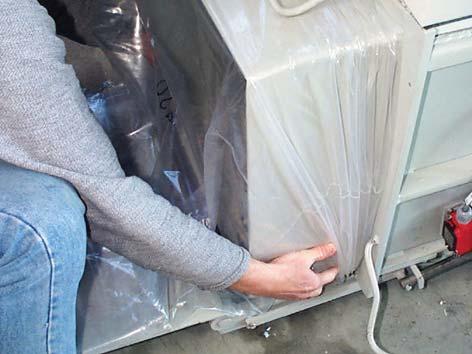
 over the discharge outlet and gather it under the 4 retaining bows (3) Close the counter plate manually again Lock the hydraulic door lock ( + ) Press the Automatic")
37 1 Accessories: PE gusseted bag U=2120mm / L=1400mm / S=0,1mm Part no.: Pull the plastic bag (2) over the discharge outlet and gather it under the 4 retaining bows (3) Close the counter plate manually again Lock the hydraulic door lock ( + ) Press the Automatic mode key on the press the white Automatic mode LED lights up Indicator: Manual mode Initial position Ready display lights up green on the shredder. Baling press status display lights up green on the shredder. 04/ _en 37


38 _en 04/2013

39 Press the start button the cutting unit and feed belt start up Place the material to be shredded on the loading table and then place batches on the feed belt If material that is not supposed to be shredded is mistakenly placed onto the conveyor belt do not try to pull it out Press the start button again the drive stops Press the R button the cutting unit and feed belt run in reverse When the R button is released the shredder comes to a stand still The material can now be removed from the conveyor belt and the shredder can be started again with the start button Note Provided the cutting unit is running in the shredding direction, you can stop it by pressing the R button. The shredded material falls through the discharge chute of the shredder directly into the hopper of the press. The press cycle is initiated by a light barrier in the hopper when it has been fi lled to a certain level. The press ram moves forward and presses the material. After the compression time has expired, the press ram automatically moves to the rear limit position. The shredder continues to run during the press cycle. The fi lling and press cycle continues until the Bale ready message appears in the display and the blue Bale ready LED lights up. The press ram goes into a position for unloading. The press and shredder switch off. 04/ _en 39
 Take hold of the counter plate using both")
 keys and keep pressing them until the")

40 4.5 Ejecting and bagging the bale Open the hydraulic door lock ( + ) Take hold of the counter plate using both hands from the front and lower it all the way down Now press both ( + ) keys and keep pressing them until the press ram automatically stops. The press ram is extended and pushes the bale into the plastic bag _en 04/2013


 04/2013 2.990.")
41 Take hold of the plastic bag at the bottom of the press fi rstly and then pull it carefully off the discharge outlet Lift the plastic bag up at its opening, so that you can stand the bale up Fold the ends over each other and seal the bag with adhesive tape Tilt the packed bale carefully on to a EURO pallet (2 bales can be stacked on a EURO pallet) 04/ _en 41
 keys for approx.")
42 Pull a new plastic bag over the discharge outlet Lift the counter plate up again Scraps of paper lying on the fl oor, can be emptied into the press through the inspection fl ap Indicator: Hopper is open! Close the inspection fl ap again Press both ( + ) keys for approx. 5 seconds to lock the hydraulic door Indicator: Manual mode Bale count: xxx (= daily bale meter reading) Press the Automatic mode key on the press the white Automatic mode LED lights up the press ram goes into the initial position the machine is ready for operation again _en 04/2013
43 4.6 Malfunctions of the baling press As soon as a malfunction occurs in the baling press, the red malfunction symbol lights up. The baling press and shredder switch off and the relevant error message appears in the text display. The Baling press status symbol lights up red on the shredder. The error number of the most recent error is stored in the error memory. Diverse, displayed error messages can be cleared by simultaneously pressing the + / keys or by turning the machine on and off. Service - Hotline: / Error numbers Code Description Remedy 1000 One of the phases is missing / power input Electrician! Check the fuses on site A phase is wrong / counter-clockwise phase rotation Electrician! Phase sequence on site / check phase rotation Oil temperature too high Let oil cool / check oil temperature sensor 1110 Defective oil temperature sensor Electrician! Replace sensor 1200 Motor overload switch was triggered. Motor too hot Check motor / reset motor overload switch 1210 Emergency stop on the press has been activated Unlock the emergency stop button 1211 Emergency stop on the shredder has been activated Unlock the emergency stop button 1221 Service door in the fi lling area of the press is open Close the inspection fl ap 1231 Defective Counter fl ap closed switch Electrician! Consult HSM customer service 1232 Counter fl ap is open Close the counter fl ap 1241 Defective Counter fl ap 90 open switch Electrician! Consult HSM customer service 1271 Extend press ram timing Check the movement of the press ram 1272 Retract press ram timing Check the movement of the press ram 1280 Counter plate not locked Electrician! Consult HSM customer service 1281 Defective Bale ready inductive switch Electrician! Consult HSM customer service 1285 Defective counter plate locked inductive switch Electrician! Consult HSM customer service 1300 Defective hardware Electrician! Consult HSM customer service 1310 Short-circuit master output stage Electrician! Consult HSM customer service 1320 Short-circuit slave output stage Electrician! Consult HSM customer service 04/ _en 43
44 4.7 Malfunctions of the shredder Overload due to paper jam Overload display (level 1 or level 2 depending on the machine model) lights up red. The drive automatically runs in reverse for several seconds. Then the cutting unit switches off. Caution! The blade rollers can still cause injuries even while they are not running. Do not reach into the cutting unit! Protective gloves should be worn at all times. Do not repetitively run the cutting unit backwards and forwards, for the purpose of removing an obstruction. This will damage the shredder. - Remove the stack of paper. - Press the automatic button on the press - Press the start button and put less paper on the feed belt Electric motor overheats Overload display (level 1 or level 2 depending on the machine model) fl ashes.red. The drive automatically switches off. - Let the motor cool down for minutes. - Press the automatic button on the press - Press the start button Emergency stop activated Display lights up red. The baling press and shredder switch off. - Activate the emergency stop control by pulling the switch bar away from the machine. - Press the automatic button on the press - Press the start button _en 04/2013

45 4.7.4 Oil reservoir empty Oil reservoir empty display lights up blue. - Refi ll the the cutting block special oil. Order no for a 5 l container After the reservoir is fi lled, the Oil reservoir empty signal is automatically deactivated. Note The shredder remains operational even when the oil reservoir is empty. 4.8 Stopping the machine - Run the machine into the initial position (with the press ram at the rear). - Switch off the main switch of the shredder and of the press - Secure the main switches against restarting - Unplug the red CEE power plug 4.9 Outdoor use Warning! For reasons of safety, only operate under supervision. The operator must ensure that unauthorized persons do not have access to the machine. When the machine is not being used, it must be shut down and secured against unauthorised use. See also the Siting the machine section 04/ _en 45
46 5 Inspection and maintenance work 5.1 Notes on maintenance Note Malfunctions which are due to inadequate or incorrect maintenance can lead to expensive repairs and lengthy machine down-times. Regular maintenance is therefore essential. For this reason we recommend a maintenance and inspection contract. Warning! Correct any damage immediately. Escaping oil can cause fi re and injury! Maintenance and repair work on the electrical system or control cabinet may only be carried out by a qualifi ed electrician or one of our service engineers All the inspection and maintenance tasks listed here apply to single-shift operation. The intervals must be reduced accordingly for multiple shift operation. The baling press must undergo a complete overhaul at least every two years. Always refer to the Safety section during maintenance and inspection work. Before performing such tasks make sure the drives and additional mechanisms of the baling press cannot be switched on unintentionally. Turn the main switch to the 0 position and secure it. Unplug the red CEE power plug. Maintenance work may only be carried out by our specialist engineers or specially trained staff. Only persons with the appropriate skills and experience in hydraulics may carry out work on the hydraulic equipment _en 04/2013
 Remove the cover (H) H")
47 5.2 Maintenance of the combined press Changing the hydraulic fluid / venting filter Change the hydraulic fl uid and the venting fi lter every 2 years Run the press ram to its rear limit position Turn off the main switch and disconnect the red CEE power plug Disassemble the shredder press combination (see Assembling the shredder press combination section) Remove the cover (H) H Venting fi lter Part. no Remove the tank cover and extract the oil with an oil suction unit The capacity of the hydraulic fl uid tank is ~ 20 l If the tank is very dirty, clean it Mount the tank cover onto the unit again Add oil until a level between the notches on the oil level dipstick is reached Oil grade: in accordance with DIN T3 multi-grade oil / ISO viscosity grade HVLP 22 ISO- Viskositätsklasse ESSO DEA SHELL ARAL BP FINA Mineralöle Mineral oils ISO VG 22 HVLP UNIVIS N 22 Astron ZHLP 22 Tellus Öl T 22 Aral Vitam HF 22 Bartran HV 22 HYDRAN HV 22 04/ _en 47
 onto the unit again Note Observe the applicable accident prevention regulations when handling cleaning agents and solvents.")
48 Run the press ram forwards and backwards several times and, whilst the press ram is as far forward as possible, recheck the oil level Fill more oil if required Screw on a new venting fi lter Mount the cover (H) onto the unit again Note Observe the applicable accident prevention regulations when handling cleaning agents and solvents. Observe the environment protection regulations when disposing of waste oil. Never mix hydraulic fl uid and cleaning agent mixtures with waste oil. Collect these substances in separate containers and dispose of them according to the regulations Lubricating the movable parts The press ram guide (black plastic blocks) is maintenance free. Do not lubricate the tracks in the press chamber! Should any grinding or humming noises arise, place a drop of biodegradable lubricating oil on the exposed tracks of the press chamber fl oor. Replace the plastic blocks of the press ram guide every 2 years. Consult HSM customer service in this regard. ÖL OIL HUILE OLIO ACEITE ÓLEO OLIE OLJA ÖLJY Lubricate all movable parts and hinges as required, especially the door hinges and the bearings of the door locks with multi-purpose grease or universal lubricating oil _en 04/2013
 - Turn off the main switch and disconnect the red CEE power plug -")
.")

49 5.3 Maintenance of the FA shredder Lubricating the drive chains and synchronized wheels (2 x per year) - Turn off the main switch and disconnect the red CEE power plug - Remove the inspection fl aps (1) in the left and right side plates. Take out the Allen screws (2). - Lubricate the drive chain of the motor and cutting unit, the drive chain of the cutting unit and feed belt, and the synchronized wheels. Recommended lubricant: K2K in accordance with DIN 51502/DIN Mount the inspection fl aps onto the unit again. 04/ _en 49
 Loosen the lock nuts (4) of the tensioning bolts (5). Tighten the feed belt evenly using the tensioning bolts.")
50 5.3.2 Retighten the feed belt Turn off the shredder Loosen the hex nuts (3) on the left and right sides of the snub roller. (Accessible from the below) Loosen the lock nuts (4) of the tensioning bolts (5). Tighten the feed belt evenly using the tensioning bolts Note Only tighten the feed belt until it stops slipping. The feed belt bearing may be damaged if it is tightened too much. Tighten the hex nuts on the snub roller and the lock nuts on the tensioning bolts again Check the directional stability of the feed belt Switch on the shredder and let it run for approx. 10 minutes. During this time, the feed belt must run in the middle of the snub roller. If it slips to the left or right edge, you must alter the setting of the snub roller Check the feed belt for wear The surface of the feed belt can become worn after long periods of use. If you can see the fabric inlay in the belt, it must be replaced. Please notify our customer service _en 04/2013


51 5.3.5 Emptying the collecting tray Empty the dirt tray under the feed belt as required Clean the area under the Shredder vacuum the particles of dirt 04/ _en 51
52 6 Storage If the shredder press combination is to be stored for a lengthy period, make sure that: the shredder press combination is disconnected from the power sources the shredder press combination is not directly exposed to the weather the hydraulic tank, pipes and hoses do not leak 7 Disposal instructions HSM baling presses / shredders have a long service life. Nevertheless, every machine reaches a time when inspections and repairs are no longer worth the trouble. The operator then faces the problem of disposing of the machine properly We will be glad to advise you about the legal regulations for disposal at the appropriate time. The baling press and shredder are made of different materials and need to be disassembled to separate the materials for recycling. (Ferrous materials, electrical components, plastics) The hydraulic tank, pipes and hoses must be drained. It is important to ensure that leaking or spilled liquids are disposed of using appropriate binding agents or technical facilities, and do not enter the water, the ground or the sewer system. In disposing of the respective hydraulic fl uids, the national legal requirements must be observed _en 04/2013
53 7.1 Disposal verifi cation form To HSM GmbH + Co. KG Austraße 1-9 D Frickingen / Germany The machine specifi ed here Designation: Baling press / Shredder Model: Machine number: Year of construction: has been disposed of according the applicable regulations. Address of the last operating company Address of the waste management company Date and signature Date and signature of the last operator of the disposal company 04/ _en 53
54 8 Using and ordering spare parts Only use original HSM spare parts! When ordering spare parts, please always provide: the complete machine number the year of construction of the baling press HSM GmbH+Co.KG Austrasse 1-9 D Frickingen Germany MODELL MASCH.-NR.: SERIEN - NR.: PRESSKRAFT: kn SPANNUNG: V Hz LEISTUNG: kw BAUJAHR: NENNSTROM: A 8.1 Customer service address HSM GmbH + Co.KG Austraße Frickingen, Germany Tel Fax support@hsm.eu _en 04/2013
55 9 Electrical circuit diagrams Electrical plan is separate in the press 04/ _en 55
56 10 KP 80 hydraulic diagram _en 04/2013
57 11 EC declaration of conformity EC declaration of conformity The manufacturer HSM GmbH + Co. KG Austraße 1-9 D Frickingen hereby declares that the described SP 5080 shredder press combination, consisting of the FA shredder and the KP 80 baling press, comply with the basic safety and health requirements of the following EC directives : 2006/42/EG 2004/108/EG Applied standards and technical specifi cations: EN1010-3:2002+A1, EN ISO :2003+A1:2009, EN ISO :2003+A1:2009, EN ISO 13857:2008, EN (2008), EN :2006+A1:2009, EN 349:1993+A1:2008,EN :2006+A1:2009, EN (01.07), EN (03.06) The individual operation of the machines is prohibited. Only the combination of the shredder and the baling press complies with EN (safety distances). Frickingen, p. p. Hubert Kötzinger Head of Environmental Engineering Product Development Authorised representative for the compilation of technical documentation: Hubert Kötzinger, HSM GmbH + Co. KG. The technical documentation in terms of Appendix VII, Part A has been created and is available at HSM GmbH + Co.KG. This declaration only relates to those machines that are in the same condition as they were when put into circulation, no regard can be to parts added later by the end user and/or any work conducted subsequently. 04/ _en 57
_en SP 5088 OPERATING MANUAL CHANNEL BALING PRESS SP Keep this instruction for future use!
 2.991.999.120_en SP 5088 OPERATING MANUAL CHANNEL BALING PRESS SP 5088 Keep this instruction for future use! HSM GmbH + Co.KG, Austraße 1-9, 88699 Frickingen / Germany Tel. + 49 75 54 2100-0 Fax + 49 75
OPERATING MANUAL CHANNEL BALING PRESS KP (Shredder-Baler combination: SP 4988 / SP 5088)
") GB OPERATING MANUAL CHANNEL BALING PRESS (Shredder-Baler combination: SP 4988 / SP 5088) Keep this instruction for future use! 6.414.999.220 Edition 08/2003 HSM - Pressen GmbH + Co.KG Bahnhofstraße 115
GB OPERATING MANUAL CHANNEL BALING PRESS (Shredder-Baler combination: SP 4988 / SP 5088) Keep this instruction for future use! 6.414.999.220 Edition 08/2003 HSM - Pressen GmbH + Co.KG Bahnhofstraße 115
FA OPERATING MANUAL SHREDDER. Powerline FA 500.3
 OPERATING MANUAL SHREDDER Powerline FA 500.3 english.990.999.0 A 07/202 Contents Proper use, warranty...3 2 Safety instructions...3 3 Overview...4 4 Dimensions...5 5 Transportation, installation...6 6
Shredder FD 8906CC Cross-Cut
 Shredder FD 8906CC Cross-Cut 1/2017 OPERATOR MANUAL Machine Specs Model: FD 8906CC Motor Power Sheet Capacity Serial #: 7.5KW (10HP) Three-phase, 220V, 50/60 Hz, 50 Amp dedicated line required, CS8365
OPERATING MANUAL ORWAK March 2005 PUBL. NO Edition 4
 GB OPERATING MANUAL ORWAK 3400 March 2005 PUBL. NO 4869057-00 Edition 4 English TABLE OF CONTENTS Safety... 82 Operating instructions... 93 Technical specifications. 104 Dimensional drawing... 104 Transport...
Edition 1, From serial no Publ. no A OM B 900, Orwak Brickman 900. Operating instructions (in the original)
") Edition 1, From serial no. 10901- Publ. no A922-90619 OM B 900, 2010-01 Orwak Brickman 900 Operating instructions (in the original) CONTENTS Safety... 2-3 Safety features... 3 Range of application... 3
Edition 1, From serial no. 10901- Publ. no A922-90619 OM B 900, 2010-01 Orwak Brickman 900 Operating instructions (in the original) CONTENTS Safety... 2-3 Safety features... 3 Range of application... 3
Illustration shows item no Z Original operating manual. Operating manual. BlueMobil 60. Item no: Z-3285
 Operating manual BlueMobil 60 Item no: Z-3285 Original operating manual Illustration shows item no Z-3285 Important Copyright It is essential that you read this manual thoroughly before the initial operation
PRODUCT SERVICE OPERATING INSTRUCTIONS BARREL PRESS HSM FP 1500 HSM FP Keep this instruction for future use! Edition 03/2000
 GB PRODUCT SERVICE OPERATING INSTRUCTIONS BARREL PRESS HSM FP 1500 HSM Keep this instruction for future use! 6.817.999.520 - Edition 03/2000 HSM - Pressen GmbH + Co.KG, Bahnhofstraße 115, 88682 Salem,
Operating and Maintenance Instructions
 EATON Germany GmbH Werk Lohmar D-53797 Lohmar Operating and Maintenance Instructions WALFORM Machine Electronically controlled - Conforms to CE MEG-WF385X Status: Sept 2011 MEG-WF385X_Stand Sept 2011 SUITABILITY
Silent TS. Nr / Ideas for dental technology / A. Made in Germany
 Silent TS Nr. 2921-0050 / 2921-1050 21-9191 30102012 / A Made in Germany Ideas for dental technology 1 2 3 4 5 6 7 8 9 10 11 12 13 14 15 16 17 18 19 20 21 22 23 24 25 26 27 28 29 30 31 Silent TS Nr. 2921-0050
Illustration shows item no Z Original operating manual. Operating manual. BlueMobil eco. Item no: Z-3278
 Illustration shows item no Z-3278 Operating manual BlueMobil eco Item no: Z-3278 Original operating manual Important Copyright It is essential that you read this manual thoroughly before the initial operation
TFV 900 OPERATING MANUAL RADIAL FAN TRT-BA-TFV900-TC-001-EN
 TFV 900 EN OPERATING MANUAL RADIAL FAN TRT-BA-TFV900-TC-001-EN Table of contents Notes regarding the operating manual... 1 Safety... 2 Information about the device... 3 Transport and storage... 4 Start-up...
OPERATIONAL & MAINTENANCE MANUAL Model 7050P Old Style with Dual Troll Bin
 Security Engineered Machinery Co., Inc OPERATIONAL & MAINTENANCE MANUAL Model 7050P Old Style with Dual Troll Bin POP-0027 Rev. 1 Revised: 01/27/2016 Security Engineered Machinery Co., Inc NATIONWIDE SERVICE
InfraTec Premium. Assembly and operating instruction. 20 min. Made in Germany. Druck Nr en/ :00 20 C
 InfraTec Premium Assembly and operating instruction Made in Germany Druck Nr. 29344379 en/ -44.11 D 1 English Table of Contents Technical data...4 Scope of delivery...4 General information...5 General
TTV 1500 / TTV 3000 OPERATING MANUAL CONVEYING FAN TRT-BA-TTV TC EN
 TTV 1500 / TTV 3000 EN OPERATING MANUAL CONVEYING FAN TRT-BA-TTV1500-3000-TC2016-26-004-EN Table of contents Notes regarding the operating manual... 2 You can download the current version of the operating
JASOPELS ROTATING FLESHING MACHINE 1-BEAM
 USER MANUAL JASOPELS ROTATING FLESHING MACHINE 1-BEAM ITEM NO. 32200067 Our quality Your choice 2 www.jasopels.com TABLE OF CONTENTS About this document... 3 Declaration of Conformity... 6 Safety... 6
Operating instructions
 Operating instructions (Translation of the original operating instructions) Type TEKA FILTERCUBE-MV TEKA Absaug- und Entsorgungstechnologie GmbH Industriestraße 13 D-46342 Velen Postfach 1137 D-46334 Velen
EP-21F Manual Letter Folder Operation Manual
 EP-21F Manual Letter Folder Operation Manual EP Equipment Co.,Ltd. Introduction Thank you for selecting EP folder. This machine is designed for efficiently folding paper up to legal size (216 356mm). To
User Guide Digital Bill Counter AB4000
 User Guide Digital Bill Counter AB4000 Warning Before turning the power on, please make sure there are no objects obstructing the operation of the rollers and wheels. Operate the machine only under normal
Grain crusher Universal. Purpose: This machine is designed for the crushing of grain in agricultural operation.
 Grain crusher Universal. Purpose: This machine is designed for the crushing of grain in agricultural operation. Operating instructions and parts catalogue This grain crusher provides you with a machine
User Manual GV25 GV35 GV702. Company information: Original instructions GV12066 (1)
") User Manual Original instructions GV25 GV35 GV702 Company information: www.vipercleaning.eu info-eu@vipercleaning.com GV12066 (1) 2012-04-10 USER MANUAL ENGLISH TABLE OF CONTENTS Introduction... 4 Manual
User Manual Original instructions GV25 GV35 GV702 Company information: www.vipercleaning.eu info-eu@vipercleaning.com GV12066 (1) 2012-04-10 USER MANUAL ENGLISH TABLE OF CONTENTS Introduction... 4 Manual
Grinding mill MISTRAL 50L (art. 650P)
") Grinding mill MISTRAL 50L (art. 650P) USE AND MAINTENANCE MANUAL RIVER SYSTEMS SRL Via Marco Polo, 33-35011 Campodarsego (Padova) Italy Tel. +39-049-9202464 - Fax: +39-049-9216057 - e-mail: info@riversystems.it
Grinding mill MISTRAL 50L (art. 650P) USE AND MAINTENANCE MANUAL RIVER SYSTEMS SRL Via Marco Polo, 33-35011 Campodarsego (Padova) Italy Tel. +39-049-9202464 - Fax: +39-049-9216057 - e-mail: info@riversystems.it
Edition 5, From serial no Publ. no OM3300, Orwak 3300 OPERATING INSTRUCTIONS (IN THE ORIGINAL)
") Edition 5, From serial no. 106000- Publ. no 4869014-00 OM3300, 2012-02 Orwak 3300 OPERATING INSTRUCTIONS (IN THE ORIGINAL) English CONTENTS Safety...82 Waste matri...82 Operating instructions...93 Technical
Edition 5, From serial no. 106000- Publ. no 4869014-00 OM3300, 2012-02 Orwak 3300 OPERATING INSTRUCTIONS (IN THE ORIGINAL) English CONTENTS Safety...82 Waste matri...82 Operating instructions...93 Technical
Electronically controlled instantaneous water heater. MCX: 27300, and models. Installation instructions
 Electronically controlled instantaneous water heater MCX: 27300, 27400 and 27600 models Installation instructions These appliances deliver water not exceeding 50 ºC in accordance with AS3498. 1. Overview
Operating instructions (translation) Stunning Device for Small Animals
 Stunning Device for Small Animals") Operating instructions (translation) GB No. 9 0232 3642 Vers.2 4-2016 KTBG mod 11 Stunning Device for Small Animals Prod. No.: 9 0232 000 Friedr. Dick GmbH & Co. KG Postfach 1173 73777 Deizisau GERMANY
Operating instructions (translation) GB No. 9 0232 3642 Vers.2 4-2016 KTBG mod 11 Stunning Device for Small Animals Prod. No.: 9 0232 000 Friedr. Dick GmbH & Co. KG Postfach 1173 73777 Deizisau GERMANY
Friwa Compact. Operating instructions EN
 Operating instructions EN Version 1.1 / Edition 09/2013 Contents 1 Key background information... 3 1.1 Limitation of liability... 3 1.2 Responsibilities of the operator... 3 1.3 Documentation... 3 1.3.1
User instructions. VA20HD, VA55HD, VA55IND and VA75IND. Commercial wet/dry vacuum cleaners CAUTION - READ THESE INSTRUCTIONS BEFORE USING THE MACHINE
 User instructions VA20HD, VA55HD, VA55IND and VA75IND Commercial wet/dry vacuum cleaners CAUTION - READ THESE INSTRUCTIONS BEFORE USING THE MACHINE 03-8112-0000 Iss.3 07/08 http://www.truvox.com/products/vacuums/valet_aqua
Operation Manual 322 KL
 Operation Manual 322 KL 8/07 von Oertzen GmbH Ferdinand-Harten-Str. 10 22949 Ammersbek Tel. +49 40 604110 Fax +49 40 6041149 www.oertzen-gmbh.de info@oertzen-gmbh.de Table of Content 1. Introduction Page
ST1. Mod. USE AND MAINTENANCE MANUAL
 Mod. USE AND MAINTENANCE MANUAL 2 Use and Maintenance Manual ---------------------------------------------------------------------------------------------------------------------------------------------------------------------------------
Stripping machine AI 01
 Translation of the original operation manual Stripping machine AI 01 EN Operation manual Before putting the machine into operation, read the operation manual! Keep manual for future use. Fabrication number
TTV 4500 / TTV 4500 HP / TTV 7000
 TTV 4500 / TTV 4500 HP / TTV 7000 EN OPERATING MANUAL AXIAL FAN TRT-BA-TTV4500-4500HP-7000-TC-003-EN Table of contents The current version of the operating manual can be found at: Notes regarding the operating
PUGMILL/MIXER. Instruction Manual NVS-07
 92895B PUGMILL/MIXER Instruction Manual NVS-07 Attention After carefully reading this manual, be sure to store it in a safe and convenient place for easy reference. Before using this unit, please read
STACK-AND-SHRED100X&100M SHREDDERS start here
 STACK-AND-SHRED100X&100M SHREDDERS start here MAX 2min 1 2 3 4 5 6 STACK-AND-SHRED100X&100M SHREDDERS instruction manual 6 autofeed technology The Stack and Shred 100X/100M has been designed to automatically
Electronically controlled instantaneous water heater. CEX 9-U: C models. Installation instructions
 Electronically controlled instantaneous water heater CEX 9-U: 27910-50 C models Installation instructions For 50 ºC models, the appliance delivers water not exceeding 50 ºC in accordance with AS3498. 1.
EYS SEPARATOR EYS 01 G. USER MANUAL for EYS SCREW-PRESS SEPARATOR MODEL EYS 01 G. User Manual for EYS 01G Screw-Press Separator
 USER MANUAL for EYS SCREW-PRESS SEPARATOR MODEL EYS 01 G User Manual for EYS 01G Screw-Press Separator Table of Contents Page 1. Introduction 2 2. General Safety Instructions 3 3. Installation 5 4. Start-up
Operating Instructions
 WD 3 Premium Operating Instructions Before first use of the unit read these operating instructions and act in accordance with them. English 5 59658050 (08/15) 10 11 12 13 14 15 16 2 3 4 Contents General
Commercial backpack vacuum cleaner
 ORIGINAL INSTRUCTIONS CAUTION READ THESE INSTRUCTIONS BEFORE USING THE MACHINE User instructions Valet BackPack Commercial backpack vacuum cleaner 03-8113-0000 Issue 6 10/10 1 2 Contents 1. General information...
Bliss Box Former Troubleshooting. 6.1 Troubleshooting Chart. Troubleshooting INTRODUCTION SAFETY PROCEDURES
 6.0 Bliss Box Former 1.0 INTRODUCTION Table 6-1 provides a logical sequence of tests that are designed to isolate problems with the Bliss Box Former machines. This table includes a list of probable causes
MV 4 MV 4 Premium. Operating Instructions. Before first use of the unit read these operating instructions and act in accordance with them.
 MV 4 MV 4 Premium Operating Instructions Before first use of the unit read these operating instructions and act in accordance with them. www.kaercher.com/register-and-win 59651790 10/13 3 4 2 5 6 7 1 8
Quality makes the Difference. AquaTREND uni. User s Manual Humidifi er for Therapeutic Air Flow
 Quality makes the Difference AquaTREND uni User s Manual Humidifi er for Therapeutic Air Flow SERIAL NUMBER HOFFRICHTER GmbH delivers all its systems with a serial number in order to ensure traceability.
Whole Room Dryer WRD, WRD/110
 Whole Room Dryer WRD, WRD/110 User Instructions Whole Room Dryers CAUTION - READ THESE INSTRUCTIONS BEFORE USING THE MACHINE 03-8117-0000 Iss.1 12/06 Fig 1 Fig 2 Fig 3 Fig 4 CONTENTS Page 1 Product information...................4
USER S MANUAL ATH WH220
 USER S MANUAL ATH WH220 INDEX INTRODUCTION... - 3 - General information s... - 3 - Description of pneumatic jack... - 4 - Operation of jack... - 5 - Technical data... - 6 - Dimension drawing... - 6 - INSTALLATION...
STACK & SHRED110X SHREDDERS. Start here AU_Rexel StackandShredManual_MZ.indd 1
 STACK & SHRED110X SHREDDERS Start here 2103110AU_Rexel StackandShredManual_MZ.indd 1 MAX 2min 1 2 2 2103110AU_Rexel StackandShredManual_MZ.indd 2 3 4 5 6 STACK & SHRED 110X SHREDDER 3 2103110AU_Rexel StackandShredManual_MZ.indd
WHITAKER BROTHERS 1628 CC 1628 SC 1628 MS. Operating Instructions. High Security Paper Shredder. Printed 08/
 WHITAKER BROTHERS 1628 CC High Security Paper Shredder Operating Instructions Printed 08/09 1.566.999.135 A 0908 1 Proper use, warranty Keep paper shredder out of the The shredder is designed exclusively
User Manual. Juice Extractor MODEL: WJE2BSLA
 User Manual Juice Extractor MODEL: WJE2BSLA 1. READ these instructions carefully before installing and operating the appliance. Keep them for further reference. 2. Record in the space below the SERIAL/MODEL
OPERATING MANUAL Gfp 255C Please read this manual carefully before operating!
 OPERATING MANUAL Gfp 255C Please read this manual carefully before operating! Unpacking, assembly, and operating videos are available at www.gfpsmoothstart.com 1 Table of Contents Gfp 255C March 2015 Contents
EHA Hoffmann International GmbH
 EHA Hoffmann International GmbH Operating Instructions EHA - Embossing Press 50-75 Professional Machine number: Model year: The side shelfs are optional and are not included in the Standard scope of delivery.
Installation manual Mini Comfort 50 S/L 07/ V EN
 Installation manual Mini Comfort 50 S/L 07/2015 - V 1.1 - EN www.veneco-ventilation.be Veneco ventilation by Elek Trends Productions nv Blauwfazantjesstraat 4 B - 7700 Moeskroen Tel. +32 (0)56 48 15 90
RSH2455G OPERATOR S MANUAL ELECTRIC QUIET CHIPPER SHREDDER
 RSH2455G ELECTRIC QUIET CHIPPER SHREDDER OPERATOR S MANUAL Important! It is essential that you read the instructions in this manual before mounting and operating this machine. Subject to technical modifications.
Electrostatic Precipitator
 Electrostatic Precipitator ESP1500E ESP3000E ESP4500E TECHNICAL & OPERATION MANUAL This manual refers to:- Model ESP1500E Serial No. E152014 Model ESP3000E Serial No. E302014 Model ESP4500E Serial No.
Installation and operating instructions. DK energy storage and DK energy buffer
 Installation and operating instructions DK energy storage and DK energy buffer Edition: 08-2015 1 Preliminary note With this DK energy storage / DK energy buffer you purchased a DK quality product. The
Electronically controlled instantaneous water heater CEX 9. CEX9: C models. Instructions for the user
 Electronically controlled instantaneous water heater CEX 9 CEX9: 27900-50 C models Instructions for the user For 50 ºC models, the appliance delivers water not exceeding 50 ºC in accordance with AS3498.
SILENT compact /
 SILT compact 2934 0000 / 2934 1000 TRANSLATION OF THE ORIGINAL INSTRUCTIONS FOR USE Made in Germany Ideas for dental technology 21-2245 21052015 / A Contents 1. Introduction...3 1.1 Symbols...3 2. Safety...3
OPERATOR S MANUAL. For BURLY ATTACHMENTS
 OPERATOR S MANUAL For BURLY ATTACHMENTS April 4, 2018 Clod-Buster Topsoil Screener LIMITED WARRANTY Burly Attachments, LLC warrants to the original Purchaser, all products, manufactured by it, to be free
Product instruction manual Easymount Wide Format Laminators
 Product instruction manual Easymount Wide Format Laminators The Easymount has been designed to be user friendly, however we strongly recommend you take a few minutes to read through this manual to ensure
CAUTION - READ THESE INSTRUCTIONS BEFORE USING THE MACHINE
 User instructions Model X46 Escalator and Travelator cleaner CAUTION - READ THESE INSTRUCTIONS BEFORE USING THE MACHINE 03-7845-0000 Iss.1 07/04 Fig 1 Fig 2 2 Contents Page 1 Product information... 4 1.1
USER S MANUAL. VCU/VCUN Series CENTRIFUGAL FAN IN SCROLL CASING
 USER S MANUAL VCU/ Series CENTRIFUGAL FAN IN SCROLL CASING 2 CONTENTS Introduction Use Delivery set Designation key Technical data Safety requirements Design and operating logic Mounting and set-up Connection
The Da-Lite Difference.
 The Da-Lite Difference. Instruction Book for senior Electrol DA-LITE SCREEN COMPANY, INC. 100 North Detroit Street Post Office Box 17 Warsaw, Indiana 46581-017 Phone: 574-267-8101 800-622-77 Fax: 574-267-7804
Silent TS. Nr / Content Introduction...1 Symbology...1 Information for Operators...2. Introduction.
 Silent TS Nr. 2921-0050 / 2921-1050 ENGLISH Content Introduction...1 Symbology...1 Information for Operators...2 Operating Instructions 1. Setup and Commissioning...2 1.1 Setup... 2 1.2 Connection to the
Electronically controlled instantaneous water heater. DEX: C models. Instructions for the user
 Electronically controlled instantaneous water heater DEX: 27930-50 C models Instructions for the user For 50 ºC models, the appliance delivers water not exceeding 50 ºC in accordance with AS3498. MADE
Electronically controlled instantaneous water heater. MCX: 27300, and models. Instructions for the user
 Electronically controlled instantaneous water heater MCX: 27300, 27400 and 27600 models Instructions for the user These appliances deliver water not exceeding 50 ºC in accordance with AS3498. 1. Overview
SPID play detector date: 07/2006 Manual date:
 SPID 20000 play detector date: 07/2006 Manual date: 04.07.2006 Operating Instruction and Documentation Serial number:... Nußbaum Hebetechnik GmbH & Co.KG//Korker Strasse 24//D-77694 Kehl-Bodersweier Tel:
A U T O X & M S H R E D D E R S. Instruction Manual.
 A U T O + 2 0 0 X & 2 0 0 M S H R E D D E R S Instruction Manual www.accobrandsasia.com X X X X 300X 2min 1 2 X 300X X 300X 3 4 5 6 autofeed technology The Auto+ X and M has been designed to automatically
Combivac Operating Instructions Combivac
 Combivac 17-36 Operating Instructions Combivac General Table of contents General...2 Table of contents...2 Information about the operating instructions...3 Liability...3 Notices in the operating instructions...3
Strip-Cut Shredder S5
 Strip-Cut Shredder S5 Manual 91604 Please carefully read through these operating instructions before using the device for the first time. In particular, please comply with the safety notices. Intended
Operating instructions
 Operating instructions firstair screw compressor FAS03 37 Read the instructions before operating the compressor! Visit us at firstaircompressor.com For support, contact us at support@firstaircompressor.com
AIRGOCLEAN 10 E OPERATING MANUAL AIR CLEANER TRT-BA-AIRGOCLEAN10E-TC-001-EN
 AIRGOCLEAN 10 E EN OPERATING MANUAL AIR CLEANER TRT-BA-AIRGOCLEAN10E-TC-001-EN Table of contents Notes regarding the operating manual... 1 You can download the current version of the operating manual and
User Guide. Portable banknote counter AB300
 User Guide Portable banknote counter AB300 Thank you for purchasing this AccuBANKER product. We recommend reading all information in the user guide to become familiar with this product. AccuBANKER and
Steam Trap BK 45 BK 45-U BK 45-LT BK 46
 Steam Trap BK 45 BK 45-U BK 45-LT BK 46 Original Installation Instructions 810437-08 Contents Foreword... 3 Availability... 3 Formatting features in the document... 3 Safety... 3 Use for the intended purpose...
Speedpocket. Sewing unit for runstitching of rectangular piped pockets. Operating Instructions. Installation Instructions. Service Instructions
 745-34 Speedpocket Sewing unit for runstitching of rectangular piped pockets Operating Instructions Installation Instructions Service Instructions Instructions for programming DAC 1 3 4 Postfach 17 03
Operating instructions Safety-monitoring module SRB 302X3. 1. About this document. Content
 8 Appendix 8.1 Wiring examples...4 8.2 Start configuration...4 8.3 Sensor configuration...4 8.4 Actuator configuration...5 Operating instructions.............pages 1 to 6 Original 9 EU Declaration of conformity
Technical Data. Name: ERIKA Automat fully automatic machine to divide and to round dough pieces of the same size
 AUTOMAT MANUAL 1 Technical Data Name: ERIKA Automat fully automatic machine to divide and to round dough pieces of the same size Type Divisions Dough Portions (in ounces) Plate Nos. 3 30 1.0 3.5 #35 4/40A
CENTRIFUGAL FAN IN SCROLL CASING. Helix S-Vent OPERATION MANUAL
 CENTRIFUGAL FAN IN SCROLL CASING Helix S-Vent EN OPERATION MANUAL Helix / S-Vent www.blaubergventilatoren.de CONTENTS CONTENTS 3 Introduction 3 Use 3 Delivery set 4 Technical data 10 Safety requirements
Installation and operating instructions. Temperature difference controller 6 inputs, 3 outputs, integrated data logger for SD card
 SOLARTHERMIE - SOLAR THERMAL - SOLAR TÉRMICO - SOLAIRE THERMIQUE - SOLARE TERMICO Installation and operating instructions Temperature difference controller 6 inputs, 3 outputs, integrated data logger for
USER GUIDE. DRENA 2 - User Manual ELECTRICAL PANEL FOR 2 MOTORS - WASTE WATER -
 USER GUIDE DRENA 2 - User Manual ELECTRICAL PANEL FOR 2 MOTORS - WASTE WATER - II CONTENTS 1. SYMBOLS AND WARNINGS... 5 2. GENERAL INFORMATION... 6 3. WARNINGS... 7 4. GENERAL DESCRIPTION... 8 5. INSTALLATION...
GRIND PRO DUAL OR DISC SANDER. Operator Manual
 GRIND PRO DUAL OR DISC SANDER Operator Manual 2 GRIND PRO DUAL OR DISC ORTHO-SANDER INTRODUCTION The Grind Pro Dual or Disc Sander is a compact, durable machine designed for fast, complete finishing work.
Edition 6, From serial no Publ. no Orwak 5030-CE. Operating manual
 Edition 6, From serial no. 78087 Publ. no 4869700-00 2008-01 Orwak 5030-CE Operating manual English CONTENTS Safety...8 2 Operating instructions...9 3 Technical specifications...10 4 Dimensional sketch...10
Operating manual BDC-654 BDC-654. EN - Version 1.1. Gebruikershandleiding. Operating manual.
 Operating manual BDC-654 Operating manual BDC-654 EN - Version 1.1 Gebruikershandleiding Operating manual BDC-654 2/16 EC DECLARATION OF CONFORMITY in accordance with Appendix II sub A of Directive 98/37/EC
CP-200 Push Button. CP Warewash Pump Instruction & Operation Manual Push Button , Rev1.0,
 CP-200 - Warewash Pump Instruction & Operation Manual Push Button 20-08881-01, Rev1.0, 25.06.2012, Page 1 of 8 Contents A) Description B) Site Survey and Installation Requirements C) Package Contents D)
Operating Manual. VIENNA Hot Display
 Operating Manual VIENNA Hot Display Operating and Maintenance instructions Please read this manual carefully before you start to operate your heated display case. Following these instructions helps you
KK70 Silent. Installation and Operating Instructions L V001
 KK70 Silent Installation and Operating Instructions 0881100001L02 1502V001 Contents Important information 1 Documentation 3 11 Warnings and symbols 3 12 Notes on copyright 3 2 Safety 4 21 Intended use
DRYTEK 1 - User Manual ELECTRICAL PANEL FOR 1 MOTOR WITH POWER FACTOR CONTROL
 DRYTEK 1 - User Manual ELECTRICAL PANEL FOR 1 MOTOR WITH POWER FACTOR CONTROL CONTENTS 1. INTRODUCTION... 5 2. WARNINGS... 6 3. GENERAL DESCRIPTION... 7 4. INSTALLATION... 8 5. CONTROL PANEL... 9 5.1
Operating Instructions!
 Operating Instructions! 3 4 Oscillation MO 16.2 / MO 40 Example 3 4 MO 16.2 The unit has to be strictly used according to the instruction manual. Keep the unit away from children and from persons not instructed
DEUTSCH Bio-Master Bio-Max
 DEUTSCH D 8217-3029-02 Bio-Master Bio-Max SVENSKA S 4. 2. 1. 3. 4. 5. 3 S SVENSKA 7. 6. 8. 9. 10. 4 SVENSKA S 11. 12. 4. 13. 4. 15. 14. 5 GB ENGLISH SAFETY PRECAUTIONS GENERAL This symbol means WARNING.
TIH 300 S / TIH 400 S / TIH 500 S / TIH 700 S / TIH 900 S / TIH 1100 S
 TIH 300 S / TIH 400 S / TIH 500 S / TIH 700 S / TIH 900 S / TIH 1100 S EN OPERATING MANUAL INFRARED HEATING PANEL TRT-BA-TIH300S-TIH400S-TIH500S-TIH700S-TIH900S-TIH1100S-TC-002-EN Table of contents Notes
POWERSHRED C OPERATING INSTRUCTIONS NOTICE D'UTILISATION MANUAL DEL PROPIETARIO BETRIEBSANLEITUNG
 POWERSHRED OPERATING INSTRUCTIONS NOTICE D'UTILISATION MANUAL DEL PROPIETARIO BETRIEBSANLEITUNG 1.490.999.113 Edition 01/03 Paper shredder ENGLISH Paper shredder Fellowes /... 3 8 FRANÇAIS Déchiqueteuse
HSM Vertical Baling Presses Waste Management Solutions for Manufacturers and Retailers
 HSM Vertical Baling Presses Waste Management Solutions for Manufacturers and Retailers ENVIRONMENTAL TECHNOLOGY With HSM Turn your waste into valuable material! Packaging can become a problem Packaging
Manual Feed Slot Opening. Wastebin. Credit Card Casters
 Model# AF300 Contents Product Diagram & Technical Specifications... 3 Warnings... 4 Installation / Safety Instructions... 5 Assembly... 6 Operation... 6-8 Care & Maintenance... 8 Troubleshooting... 9 Warranty,
EHA Hoffmann International GmbH
 EHA Hoffmann International GmbH User manual EHA-TRANSPRINT HP 2020 Machine-No.: Year: EHA Hoffmann International GmbH Michelsbergstraße 24 D-57080 Siegen/Germany Telephone: +49 271 39 32-0 Telefax: +49
INSTALLATION and OPERATION BALL WASHER MODEL NO: BW-022
 Easy Picker Golf Products, Inc. 415 Leonard Blvd. N., Lehigh Acres, FL 33971 PH: 239-368-6600 FAX: 239-369-1579 Service: 800-982-4653 SALES: 800-641-4653 www.easypicker.com salesdept@easypicker.com INSTALLATION
IMPORTANT SAFETY INSTRUCTIONS TABLE OF CONTENTS SAVE THESE INSTRUCTIONS!
 TABLE OF CONTENTS IMPORTANT SAFETY INSTRUCTIONS Table of Contents Page 2 Important Safety Instructions Page 3 General Safety Instructions Page 4 List of Main Parts, Technical Specifications Page 6 Contents
Panel Fan Series Operators Manual (Galvanized and Polymer)
") Panel Fan Series Operators Manual (Galvanized and Polymer) 52" Belt Drive, Galvanized Panel Fan with Three Wing Blade IMPORTANT: READ AND SAVE THESE INSTRUCTIONS Read all instructions carefully before
Panel Fan Series Operators Manual (Galvanized and Polymer) 52" Belt Drive, Galvanized Panel Fan with Three Wing Blade IMPORTANT: READ AND SAVE THESE INSTRUCTIONS Read all instructions carefully before
Operating instructions Safety-monitoring module SRB 302X3. 1 About this document
 1 About this document Operating instructions... pages 1 to 6 Translation of the original operating instructions 1.1 Function This operating instructions manual provides all the information you need for
User Manual. Wine Cellar
 User Manual Wine Cellar MODEL: WWT060MB WWT080MB WWT100MB WWT120MB 1. READ these instructions carefully before installing and operating the Wine Cellar. Keep them for further reference. 2. Record in the
DOMINATOR IT - ISTRUZIONI ORIGINALI IN LINGUA ITALIANA
 DOMINATOR IT - ISTRUZIONI ORIGINALI IN LINGUA ITALIANA IT PAGE 1 EN PAGE 5 F PAGE 9 D PAGE 13 E PAGE 17 NL PAGE 21 P PAGE 25 DK PAGE 29 FIN PAGE 33 N PAGE 37 S PAGE 41 GR PAGE 45 PL PAGE 49 RO PAGE 53
BMA 0010 Instruction and Installation Manual Oil-Air Cooler ACN
 BMA 0010 Instruction and Installation Manual Oil-Air Cooler ACN Compact oil-air cooler High cooling capacity High operating pressure Low pressure loss Low noise emission Contents 1. Basic information 3
Waste water ejection unit
 Waste water ejection unit Over ground box SWH 500/50-80 SWH 500/50-80 Operation manual Table of contents: Page Declaration of conformity... 3 1. General... 4 1.1 Introduction... 4 1.2 Enquiries and orders...
Tornado Operations & Maintenance Manual
 TORNADO INDUSTRIES 7401 W. LAWRENCE AVENUE CHICAGO, IL 60706 (708) 867-5100 FAX (708) 867-6968 www.tornadovac.com Tornado Operations & Maintenance Manual MODEL NO. 99690 BD 22/14, 99720 BD 26/14 L9722
MV 2. Operating Instructions. Before first use of the unit read these operating instructions and act in accordance with them.
 MV 2 Operating Instructions Before first use of the unit read these operating instructions and act in accordance with them. www.kaercher.com/register-and-win 59651870 11/13 2 12 3 Contents General notes..................5
Declaration of Conformity
 Declaration of Conformity Fellowes Manufacturing Company Yorkshire Way, West Moor Park, Doncaster, South Yorkshire, DN3 3FB, England declares that the model Voyager A3 conforms with the requirements of